platform-based synthesis for field-programmable...
TRANSCRIPT

Page 1
PlatformPlatform--Based Synthesis for Based Synthesis for FieldField--Programmable Programmable SOCsSOCs
Prof. Jason CongProf. Jason [email protected]@cs.ucla.edu
UCLA Computer Science DepartmentUCLA Computer Science Department
OutlineOutlineMotivationMotivation
xPilot xPilot system frameworksystem framework
BehaviorBehavior--level synthesis in level synthesis in xPilotxPilotAdvantages of behavioral synthesisAdvantages of behavioral synthesisSchedulingSchedulingResource bindingResource binding
SystemSystem--level synthesis in level synthesis in xPilotxPilotSynthesis for ASIP platformsSynthesis for ASIP platformsDesign exploration for heterogeneous Design exploration for heterogeneous MPSoCsMPSoCs
ConclusionsConclusions
Page 2
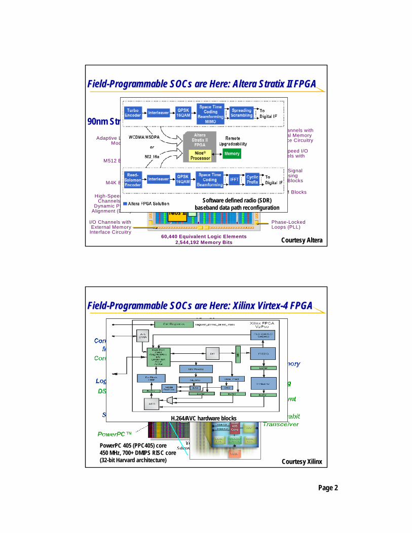
FieldField--Programmable Programmable SOCsSOCs are Here: are Here: AlteraAltera StratixStratix II FPGAII FPGA
90nm Stratix II 2S60Adaptive Logic
Modules
M512 Block
M4K Block
High-Speed I/OChannels with
Dynamic Phase Alignment (DPA)
I/O Channels with External Memory
Interface Circuitry
M-RAM Blocks
I/O Channels with External Memory Interface Circuitry
Digital Signal Processing (DSP) Blocks
Phase-Locked Loops (PLL)
High-Speed I/O Channels withDPA
60,440 Equivalent Logic Elements2,544,192 Memory Bits Courtesy Courtesy AlteraAltera
Soft core µProc
Nios II
Nios II /f185MHz< 900ALMs (<1800LEs)218 Max DMIPS
Nios II
Avalo
n™Bu
s
IP
IPSoftware defined radio (SDR) baseband data path reconfiguration
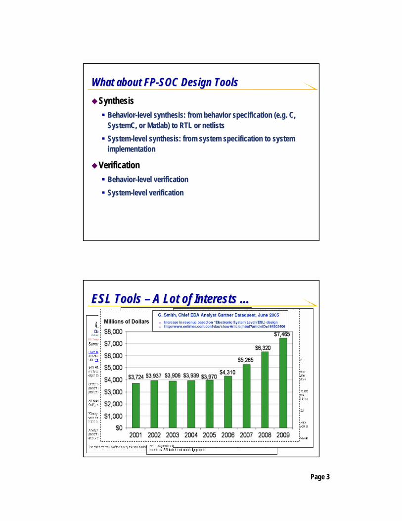
FieldField--Programmable Programmable SOCsSOCs are Here: are Here: XilinxXilinx VirtexVirtex--4 FPGA4 FPGA
Courtesy Courtesy XilinxXilinx
PowerPC 405 (PPC405) core 450 MHz, 700+ DMIPS RISC core (32-bit Harvard architecture)
Micro-Blaze
Soft core µProc
MicroBlaze180MHz< ~1300 LUTs166 DMIPS
IBM
Core
Conn
ect™
Bus
IP
IP
H.264/AVC hardware blocks
Page 3
What about FPWhat about FP--SOC Design ToolsSOC Design ToolsSynthesisSynthesis
BehaviorBehavior--level synthesis: from behavior specification (e.g. C, level synthesis: from behavior specification (e.g. C, SystemCSystemC, or , or MatlabMatlab) to RTL or ) to RTL or netlistsnetlistsSystemSystem--level synthesis: from system specification to system level synthesis: from system specification to system implementationimplementation
VerificationVerificationBehaviorBehavior--level verificationlevel verificationSystemSystem--level verificationlevel verification
ESL Tools ESL Tools –– A Lot of Interests A Lot of Interests ……

Page 4
GartnerDataquestGartnerDataquest’’ss ESL Landscape, 2005ESL Landscape, 2005
xPilot: PlatformxPilot: Platform--Based Based Synthesis SystemSynthesis System
xPilot
Behavioral SynthesisProcessor & Architecture
Synthesis
SSDM(System-Level
Synthesis Data Model)
FPSoC
Interface Synthesis
Analysis
Mapping
Profiling
Processor Cores+ Executables
Drivers + Glue LogicCustom Logic
xPilot Front EndxPilot Front End
SystemCSystemC/C/C Platform Description Platform Description & Constraints& Constraints
Uniqueness of Uniqueness of xPilotxPilotPlatformPlatform--based synthesis and optimizationbased synthesis and optimizationCommunicationCommunication--centric synthesis with interconnect optimizationcentric synthesis with interconnect optimization

Page 5
OutlineOutlineMotivationMotivation
xPilot xPilot system frameworksystem framework
BehaviorBehavior--level synthesis in level synthesis in xPilotxPilotAdvantages of behavioral synthesisAdvantages of behavioral synthesisSchedulingSchedulingResource bindingResource binding
SystemSystem--level synthesis in level synthesis in xPilotxPilotSynthesis for ASIP platformsSynthesis for ASIP platformsDesign exploration for heterogeneous Design exploration for heterogeneous MPSoCsMPSoCs
ConclusionsConclusions
Motivation (1)Motivation (1)Design complexity is outgrowing the traditional RTL Design complexity is outgrowing the traditional RTL methodmethod
Behavioral synthesis Behavioral synthesis −− a critical technology for enabling the a critical technology for enabling the move to higher level of abstractionmove to higher level of abstractionReasons for previous failuresReasons for previous failures•• Lack of a compelling reason: design complexity is still manageabLack of a compelling reason: design complexity is still manageable a le a
decade of agodecade of ago•• Lack of a solid RTL foundationLack of a solid RTL foundation•• Lack of consideration of physical realityLack of consideration of physical reality
Page 6
Motivation (2)Motivation (2)Behavioral synthesis provides combined advantagesBehavioral synthesis provides combined advantages
Shorter verification/simulation cycleShorter verification/simulation cycleBetter complexity management, faster time to marketBetter complexity management, faster time to marketRapid system explorationRapid system exploration•• Quick evaluation of different hardware/software boundariesQuick evaluation of different hardware/software boundaries•• Fast exploration of multiple microFast exploration of multiple micro--architecture alternativesarchitecture alternatives
Higher quality of resultsHigher quality of results•• PlatformPlatform--based synthesis & optimizationbased synthesis & optimization•• Full consideration of physical realityFull consideration of physical reality
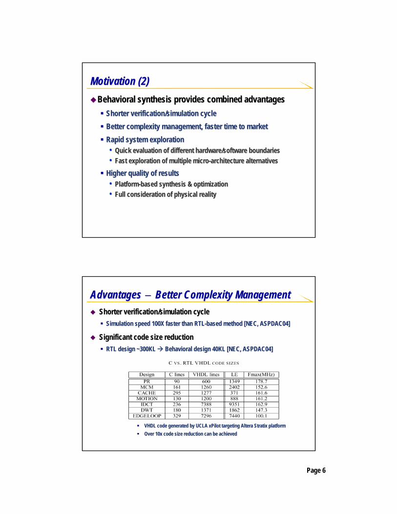
Advantages Advantages −− Better Complexity ManagementBetter Complexity ManagementShorter verification/simulation cycleShorter verification/simulation cycle
Simulation speed 100X faster than RTLSimulation speed 100X faster than RTL--based method based method [NEC, ASPDAC04][NEC, ASPDAC04]
Significant code size reductionSignificant code size reductionRTL design ~300KL RTL design ~300KL Behavioral design 40KL [NEC, ASPDAC04]Behavioral design 40KL [NEC, ASPDAC04]
VHDL code generated by UCLA xPilot targeting VHDL code generated by UCLA xPilot targeting AlteraAltera Stratix platformStratix platformOver 10x code size reduction can be achievedOver 10x code size reduction can be achieved
Page 7
Advantages Advantages −− Rapid System Exploration (1)Rapid System Exploration (1)Quick evaluation of various amounts of process level Quick evaluation of various amounts of process level concurrency and different hardware/software boundariesconcurrency and different hardware/software boundaries
Example: Motion-JPEG implementation-All HW implementation-All SW implementation (using embedded processors)-SW/HW co-design: optimal partitioning?
-Repeated manual RTL coding is not solution!
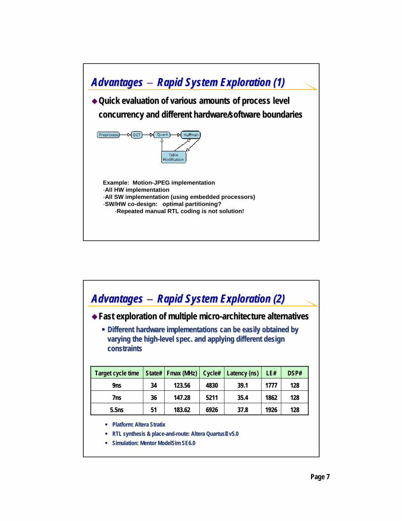
Advantages Advantages −− Rapid System Exploration (2)Rapid System Exploration (2)Fast exploration of multiple microFast exploration of multiple micro--architecture alternativesarchitecture alternatives
Different hardware implementations can be easily obtained by Different hardware implementations can be easily obtained by varying the highvarying the high--level spec. and applying different design level spec. and applying different design constraintsconstraints
19261926
18621862
17771777
LE#LE#
128128
128128
128128
DSP#DSP#
69266926
52115211
48304830
Cycle#Cycle#
37.837.8
35.435.4
39.139.1
Latency (ns)Latency (ns)
183.62183.6251515.5ns5.5ns
147.28147.2836367ns7ns
123.56123.5634349ns9ns
FmaxFmax (MHz)(MHz)State#State#Target cycle timeTarget cycle time
Platform: Platform: AlteraAltera StratixStratixRTL synthesis & placeRTL synthesis & place--andand--route: route: AlteraAltera QuartusIIQuartusII v5.0v5.0Simulation: Mentor Simulation: Mentor ModelSimModelSim SE6.0SE6.0

Page 8
Advantages Advantages −− Higher Quality of Results (1)Higher Quality of Results (1)PlatformPlatform--based synthesis & optimizationbased synthesis & optimization
The quality of a RTL design is platformThe quality of a RTL design is platform--dependentdependentDesigners often lack the complete and detail knowledge of the taDesigners often lack the complete and detail knowledge of the target rget platformplatform
7.6888 DSP BlocksDSPMUL-24bx24b3.8332 DSP BlocksDSPMUL-18bx18b4.658264 LUTsMUX16to1-24b2.92120 LUTsMUX8to1-24b2.6133 LUTsADDSUB-32b2.2725 LUTsADDSUB-24b
Delay (ns)AreaResource
Platform: Platform: AlteraAltera StratixStratixRTL synthesis & placeRTL synthesis & place--andand--route: route: AlteraAltera QuartusIIQuartusII v5.0v5.0
4.74.73.83.82.82.8
3.73.72.92.92.02.0
2.82.81.81.80.580.58
3X3 Delay Matrix
(0,0)
(95,61)
Motivation Motivation −− Higher Quality of Results (2)Higher Quality of Results (2)CommunicationCommunication--centric synthesis & optimization with full centric synthesis & optimization with full consideration of physical realityconsideration of physical reality
System performance & power is dominated by interconnectSystem performance & power is dominated by interconnectIt is difficult for designers to consider physical layout at theIt is difficult for designers to consider physical layout at the RT levelRT level
Data transfer
add1
mul1
add2
mul2LayoutLayout--aware performance aware performance optimizationoptimizationOverlap computation with communicationOverlap computation with communication
LayoutLayout--aware power aware power optimizationoptimization
F
C2’
>
2*, 3* 5*
4*
< mul1(2,5,6)
mul2(3,4)
6*
mul1(2,4,5)
mul2(3,6)
Binding solution 2:Binding solution 2:
mulmul22 can be powered can be powered off when false branch off when false branch is taken is taken
T
Binding solution 1:Binding solution 1:
Both multipliers keep Both multipliers keep activeactive

Page 9
xPilot: BehavioralxPilot: Behavioral--toto--RTL Synthesis Flow RTL Synthesis Flow Behavioral spec.
in C/SystemC
RTL + constraints
SSDMSSDM
µArch-generation & RTL/constraints generation
Verilog/VHDL/SystemCFPGAs: Altera, Xilinx ASICs: Magma, Synopsys, …
Presynthesis optimizationsLoop unrolling/shiftingStrength reduction / Tree height reductionBitwidth analysisMemory analysis …
FPGAs/ASICsFPGAs/ASICs
Frontendcompiler
Frontendcompiler
Platform description
Core synthesis optimizationsSchedulingResource binding, e.g., functional unit binding register/port binding
xPilot front-end
SystemC elaboration
xPilot synthesis engine
SystemCSystemC--toto--RTL Compilation FlowRTL Compilation Flow
Netlist in XML Behavioral IR (CDFG)
Platform description
AST
SystemC specification
SSDM
Output files (Timing/Area,RT VHDL & Constraints)

Page 10
Restricted Behavioral C Subset Restricted Behavioral C Subset Data types:Data types:
Primitive integer types: char, byte, short, Primitive integer types: char, byte, short, intint, long, long……OneOne--dimension arrays of primitive integer typesdimension arrays of primitive integer types
Operations:Operations:All arithmetic and logic operations: +, All arithmetic and logic operations: +, --, *, /, >>, &, ..., *, /, >>, &, ...
Control flow statements:Control flow statements:while, for, switchwhile, for, switch--case, ifcase, if--thenthen--else, break, continue, return, ...else, break, continue, return, ...
Restricted Behavioral C Subset (cont.)Restricted Behavioral C Subset (cont.)UnsynthesizableUnsynthesizable
RecursionsRecursionsPointers Pointers Dynamic memory allocations and system callsDynamic memory allocations and system callsIrregular jumps, e.g., Irregular jumps, e.g., gotosgotos

Page 11
SystemSystem--level Synthesis Data Modellevel Synthesis Data ModelSSDMSSDM (System(System--level Synthesis Data Model)level Synthesis Data Model)
Hierarchical Hierarchical netlistnetlist of concurrent processes and communication of concurrent processes and communication channelschannels
Each leaf process contains a sequential program which is represeEach leaf process contains a sequential program which is represented nted by an extended LLVM IR with hardwareby an extended LLVM IR with hardware--specific semanticsspecific semantics•• Port / IO interfaces, bitPort / IO interfaces, bit--vector manipulations, cyclevector manipulations, cycle--level notationslevel notations
HardwareHardware--Specific SSDM SemanticsSpecific SSDM SemanticsProcess port/interface semanticsProcess port/interface semantics
FIFO: FIFO: FifoReadFifoRead() / () / FifoWriteFifoWrite()()Buffer: Buffer: BuffReadBuffRead() / () / BuffWriteBuffWrite()()Memory: Memory: MemReadMemRead() / () / MemWriteMemWrite()()
BitBit--vector manipulationvector manipulationBit extraction / concatenation / insertionBit extraction / concatenation / insertionBitBit--width attributes for every operation and every valuewidth attributes for every operation and every value
CycleCycle--level notationlevel notationClock: Clock: waitClockEventwaitClockEvent()()
Page 12
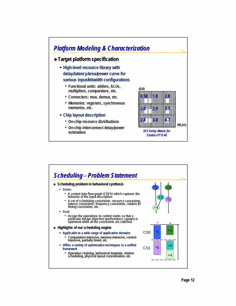
Platform Modeling & CharacterizationPlatform Modeling & CharacterizationTarget platform specificationTarget platform specification
HighHigh--level resource library with level resource library with delay/latency/area/power curve for delay/latency/area/power curve for various input/various input/bitwidthbitwidth configurationsconfigurations•• Functional units: adders, Functional units: adders, ALUsALUs, ,
multipliers, comparators, etc.multipliers, comparators, etc.•• Connectors: Connectors: muxmux, , demuxdemux, etc., etc.•• Memories: registers, synchronous Memories: registers, synchronous
memories, etc.memories, etc.
Chip layout descriptionChip layout description•• OnOn--chip resource distributionschip resource distributions•• OnOn--chip interconnect delay/power chip interconnect delay/power
estimationestimation
4.74.73.83.82.82.8
3.73.72.92.92.02.0
2.82.81.81.80.580.58
3X3 Delay Matrix for Stratix-EP1S40
(0,0)
(95,61)
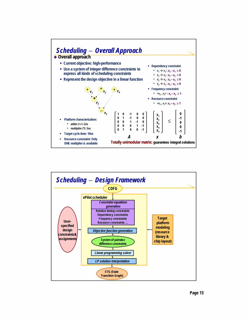
SchedulingScheduling−− Problem StatementProblem StatementScheduling problem in behavioral synthesisScheduling problem in behavioral synthesis
Given: • A control data flow graph (CDFG) which captures the
behavior of the input description• A set of scheduling constraints: resource constraints,
latency constraints, frequency constraints, relative IO timing constraints, etc.
Goal:• Assign the operations to control states so that a
particular design objective (performance / power) is optimized while all the constraints are satisfied.
Highlights of our scheduling engineHighlights of our scheduling engineApplicable to a wide range of application domainsApplicable to a wide range of application domains•• ComputationComputation--intensive, memoryintensive, memory--intensive, controlintensive, control--
intensive, partially timed, etc.intensive, partially timed, etc.Offers a variety of optimization techniques in a unified Offers a variety of optimization techniques in a unified frameworkframework•• Operation chaining, behavioral template, relative Operation chaining, behavioral template, relative
scheduling, physical layout consideration, etc.scheduling, physical layout consideration, etc.
+4
+2
*5
*1
+3
CS0
* +
+3
*1
*5
+2
+4
CS1
Page 13
Scheduling Scheduling −− Overall ApproachOverall ApproachOverall approachOverall approach
Current objective: highCurrent objective: high--performanceperformanceUse a system of integer difference constraints to Use a system of integer difference constraints to express all kinds of scheduling constraintsexpress all kinds of scheduling constraintsRepresent the design objective in a linear functionRepresent the design objective in a linear function
Dependency constraint Dependency constraint •• vv11 vv33 : : xx33 –– xx11 ≥ ≥ 00•• vv22 vv33 : : xx33 –– xx22 ≥ ≥ 00•• vv33 vv55 : : xx44 –– xx33 ≥ ≥ 00•• vv44 vv55 : : xx55 –– xx44 ≥ ≥ 00
Frequency constraint Frequency constraint •• <<vv22 ,, vv55> : > : xx55 –– xx22 ≥ ≥ 11
Resource constraintResource constraint•• <<vv22 ,, vv33>: >: xx33 –– xx22 ≥ ≥ 11
+ *
*
−
+v1 v2
v3
v4
v5
Platform characterization:Platform characterization:•• adder (+/adder (+/––) 2ns) 2ns•• multipilermultipiler (*): 5ns(*): 5ns
Target cycle time: 10nsTarget cycle time: 10nsResource constraint: Only Resource constraint: Only ONE multiplier is availableONE multiplier is available
1 0 -1 0 00 1 -1 0 00 0 1 -1 00 0 0 1 -10 1 0 0 -1
X1X2X3X4X5
0-100-1
≤
A x bTotally Totally unimodularunimodular matrix: matrix: guarantees integral solutionsguarantees integral solutions
Scheduling Scheduling −− Design FrameworkDesign Framework
xPilot scheduler
STG (State Transition Graph)
System of pairwisedifference constraints
Relative timing constraintsRelative timing constraintsDependency constraintsDependency constraintsFrequency constraintsFrequency constraints
Resource constraints Resource constraints ……
Constraint equations generation
Objective function generation
CDFG
Linear programming solver
LP solution interpretation
User-specified
design constraints&assignments
Target platformmodeling(resource library &
chip layout)

Page 14
Unified Resource BindingUnified Resource BindingAn efficient architectural exploration An efficient architectural exploration frameworkframeworkSimultaneous functional unit, Simultaneous functional unit, register, and port bindingregister, and port bindingEmphasize on the interconnect and Emphasize on the interconnect and steering logic networkssteering logic networksGuided by a flexible cost evaluation Guided by a flexible cost evaluation engine to achieve different engine to achieve different objectives, e.g., performance, area, objectives, e.g., performance, area, power, etc.power, etc.Extendable to exploit physical layout Extendable to exploit physical layout informationinformation
xPilot architecture exploration
Iteration
No
Yes
Register Allocation/Binding
FU Allocation/Binding
Baseline Register Binding
Improved?
STG (State Transition Graph)
Platform info && User-specified constraints
Datapath model for estimation
STG + Best Datapath Models
Resource BindingResource Binding−− Problem StatementProblem StatementResource binding problemResource binding problem
Given: (1) A scheduled control data flow graph, i.e., STG; (2) Design constraints: performance, delay, or power, etc.Goal: Assign the operations and variables to functional units and register, respectively, so that their executions or lifetimes are not conflicted, and all of the design constraints are satisfied.
Properties of the problemProperties of the problemFU and register binding are highly FU and register binding are highly correlatedcorrelatedSimultaneous FU and register binding Simultaneous FU and register binding considering interconnection is very considering interconnection is very difficultdifficult
+1
+2
ALU
Two binding solutions:Two binding solutions:Which one is better?Which one is better?The answer depends on:The answer depends on:
1.1. How large are the MUX and How large are the MUX and ALU (platformALU (platform--dependent)dependent)
2.2. Performance and area Performance and area constraintsconstraints
MUX
ALU ALU
BindingBinding

Page 15
Island A
Data Import Logic
Distributed RegisterDistributed Register--File (DRF) File (DRF) MicroarchitectureMicroarchitecture
LocalRegister
File
LocalRegister
File
FU pool
MULALU
Buffers
Island B
ALU’
Island C
Regular datapath structure
Provides opportunities to hide large MUX into register-files
Computations and communications are localized
Allow replicated values among islands Enables efficient optimizations to control interconnects among islands
Advantages of DRF Advantages of DRF MicroarchitectureMicroarchitecture21
DFG
(Part of Chen DCT)
Scheduled DFG
Resource constraint: 1 FU
DRF result:Datapath with more regularityHide MUX into the register fileEspecially effective for FPGA designs
Discrete register result
MUX implementation may be very expensive (e.g., on FGPAs)
1
2
4
3
1
2

Page 16
PlatformPlatform--Based Interface SynthesisBased Interface SynthesisFocus on sequential communication channelsFocus on sequential communication channels
Data must be read and written in the same order Data must be read and written in the same order •• Example: FIFO (FSL in Example: FIFO (FSL in VirtexIIVirtexII), Bus (in both ), Bus (in both StratixStratix and and VirtexVirtex))
Order may have dramatic impact on performanceOrder may have dramatic impact on performance•• Best order should guarantee that no data transmission on criticaBest order should guarantee that no data transmission on critical l
path are delayed by nonpath are delayed by non--critical transmissioncritical transmission
Interface synthesis for sequential communication channelsInterface synthesis for sequential communication channelsConsider both the behavior model and communication topology Consider both the behavior model and communication topology to detect the optimal transmission orderto detect the optimal transmission orderAutomatically do interface generation for sequential Automatically do interface generation for sequential communication units, as well as code transformation for behaviorcommunication units, as well as code transformation for behaviormodels models
Overall Approach to Interface SynthesisOverall Approach to Interface SynthesisReduce the order detection Reduce the order detection problem to a minproblem to a min--latecncylatecncyscheduling problem:scheduling problem:
Merge the Merge the CDFGsCDFGs of all of all processes processes Each element to be Each element to be transferred on FIFO are transferred on FIFO are transformed to a special transformed to a special operation Toperation TOnly one T can be scheduled Only one T can be scheduled at each step.at each step.
Example shown on right, Example shown on right, assuming only 1 cycle is assuming only 1 cycle is needed for FIFO operationneeded for FIFO operation
- -
-
T1
+
-
-T1
T3
T2
-
T2 T3
+
Merged CDFG
Scheduling result, order is (1,3,2)
*
Process 1
Process 2
*

Page 17
Experimental Results Experimental Results −− Benchmark SuiteBenchmark SuiteBenchmark suiteBenchmark suite
PR, MCM:PR, MCM:•• DSP kernels: pure additions/subtractions and multiplicationsDSP kernels: pure additions/subtractions and multiplications
CACHECACHE•• Cache controller: controlCache controller: control--intensive designs with cycleintensive designs with cycle--accurate I/O operationsaccurate I/O operations
MOTION: MOTION: •• Motion compensation algorithm for MPEGMotion compensation algorithm for MPEG--1 decoder: control1 decoder: control--intensive with modest intensive with modest
amount of computationsamount of computationsIDCT: IDCT: •• JPEG inverse discrete cosine transform: computation intensiveJPEG inverse discrete cosine transform: computation intensive
DWT: DWT: •• JPEG2000 discrete wavelet transform: computation intensive with JPEG2000 discrete wavelet transform: computation intensive with modest control modest control
flowflowEDGELOOP: EDGELOOP: •• Extracted from H.264 decoder: a very complex design, features a Extracted from H.264 decoder: a very complex design, features a mix of mix of
computation, control, and memory accessescomputation, control, and memory accesses
SystemCSystemC/C/C--toto--FPGA Design Flow (FPGA Design Flow (AlteraAltera))
xPilot xPilot behavioral behavioral synthesissynthesis
SSDM/CDFGSSDM/CDFGBehavioral synthesisBehavioral synthesis
RTL generationRTL generationSSDM/FSMDSSDM/FSMD
FSM with FSM with DatapathDatapathin VHDLin VHDL
Floorplan and/or multiFloorplan and/or multi--cycle path constraintscycle path constraints
SSDM(System-Level
Synthesis Data Model)
SystemCSystemC/C specification/C specification
FrontFront--end compilerend compiler
Platform description Platform description & constraints& constraints
AlteraAltera QuartusIIQuartusII v5.0v5.0
Stratix/StratixIIStratix/StratixIIdevice configurationsdevice configurations
Page 18
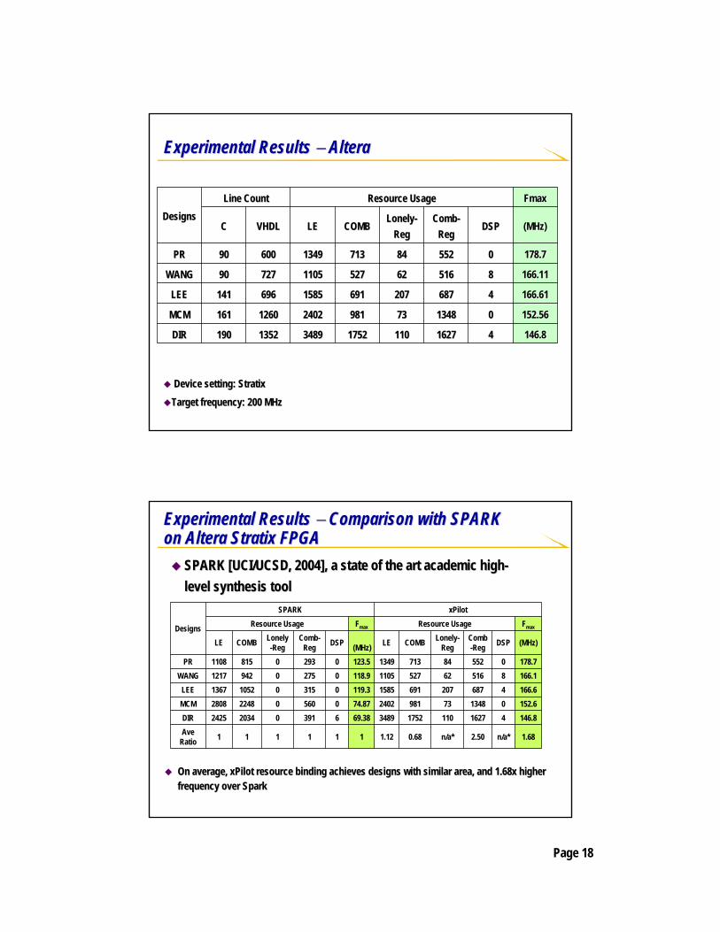
Experimental Results Experimental Results −− AlteraAltera
Device setting: Device setting: StratixStratix
Target frequency: 200 MHzTarget frequency: 200 MHz
146.8146.84416271627110110175217523489348913521352190190DIRDIR
152.56152.56001348134873739819812402240212601260161161MCMMCM
166.61166.614468768720720769169115851585696696141141LEELEE
166.11166.11885165166262527527110511057277279090WANGWANG
178.7178.7005525528484713713134913496006009090PRPR
(MHz)(MHz)DSPDSPCombComb--RegReg
LonelyLonely--RegReg
COMBCOMBLELEVHDLVHDLCC
FmaxFmaxResource UsageResource UsageLine CountLine CountDesignsDesigns
On average, On average, xPilot resource binding achieves designs with similar area, and xPilot resource binding achieves designs with similar area, and 1.68x higher 1.68x higher frequency over Sparkfrequency over Spark
1.68n/a*2.50n/a*0.681.12111111Ave Ratio
146.8416271101752348969.386391020342425DIR152.60134873981240274.870560022482808MCM166.646872076911585119.30315010521367LEE166.18516625271105118.9027509421217WANG178.70552847131349123.5029308151108PR
(MHz)DSPComb-Reg
Lonely-RegCOMBLE(MHz)DSPComb-
RegLonely-RegCOMBLE
FmaxResource UsageFmaxResource UsagexPilotSPARK
Designs
Experimental Results Experimental Results −− Comparison with SPARK Comparison with SPARK on on AlteraAltera StratixStratix FPGAFPGA
SPARK [UCI/UCSD, 2004], a state of the art academic highSPARK [UCI/UCSD, 2004], a state of the art academic high--level synthesis toollevel synthesis tool

Page 19
SystemCSystemC/C/C--toto--FPGA Design Flow (Xilinx)FPGA Design Flow (Xilinx)
xPilot xPilot behavioral behavioral synthesissynthesis
SSDM/CDFGSSDM/CDFGBehavioral synthesisBehavioral synthesis
RTL generationRTL generationSSDM/FSMDSSDM/FSMD
FSM with FSM with DatapathDatapathin VHDLin VHDL
Floorplan and/or multiFloorplan and/or multi--cycle path constraintscycle path constraints
SSDM(System-Level
Synthesis Data Model)
SystemCSystemC/C specification/C specification
FrontFront--end compilerend compiler
Platform description Platform description & constraints& constraints
Xilinx ISE i7.1Xilinx ISE i7.1
VirtexII(VirtexII(--Pro)/VirtexPro)/Virtex--44device configurationsdevice configurations
Experimental Results Experimental Results −− XilinxXilinx
Device setting: xc2vp30 Device setting: xc2vp30 --77
Target frequency: 200 MHzTarget frequency: 200 MHz
98.8198.815656173217321002100297997913521352190190DIRDIR
110.38110.383030128212821207120788788712601260161161MCMMCM
131.93131.931919659659484484356356696696141141LEELEE
133.51133.5115155885884644643573577277279090WANGWANG
146.84146.8416165645644164163313316006009090PRPR
(MHz)(MHz)DSPDSP(FF)(FF)(LUT)(LUT)SlicesSlicesVHDLVHDLCC
FmaxFmaxResource UsageResource UsageLine CountLine CountDesignsDesigns
Page 20
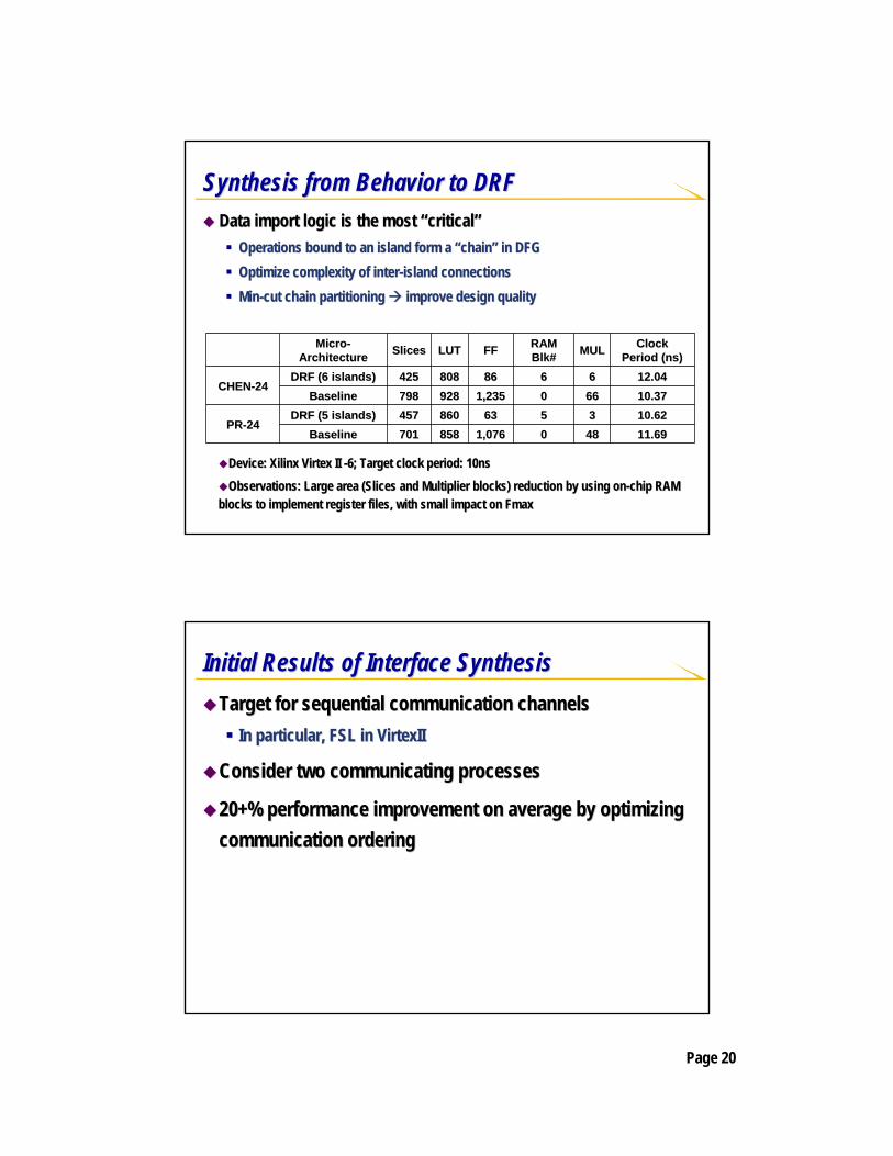
Synthesis from Behavior to DRFSynthesis from Behavior to DRFData import logic is the most Data import logic is the most ““criticalcritical””
Operations bound to an island form a Operations bound to an island form a ““chainchain”” in DFGin DFGOptimize complexity of interOptimize complexity of inter--island connectionsisland connectionsMinMin--cut chain partitioning cut chain partitioning improve design qualityimprove design quality
11.6911.694848001,0761,076858858701701BaselineBaseline10.6210.6233556363860860457457DRF (5 islands)DRF (5 islands)
PRPR--2424
10.3710.376666001,2351,235928928798798BaselineBaseline12.0412.0466668686808808425425DRF (6 islands)DRF (6 islands)
CHENCHEN--2424
Clock Clock Period (ns)Period (ns)MULMULRAM RAM
BlkBlk##FFFFLUTLUTSlicesSlicesMicroMicro--ArchitectureArchitecture
Device: Device: XilinxXilinx VirtexVirtex II II --6; Target clock period: 10ns6; Target clock period: 10ns
Observations: Large area (Slices and Multiplier blocks) reductioObservations: Large area (Slices and Multiplier blocks) reduction by using onn by using on--chip RAM chip RAM blocks to implement register files, with small impact on Fmaxblocks to implement register files, with small impact on Fmax
Initial Results of Interface SynthesisInitial Results of Interface SynthesisTarget for sequential communication channelsTarget for sequential communication channels
In particular, FSL in In particular, FSL in VirtexIIVirtexII
Consider two communicating processesConsider two communicating processes
20+% performance improvement on average by optimizing 20+% performance improvement on average by optimizing communication orderingcommunication ordering

Page 21
OutlineOutlineMotivationMotivation
xPilot xPilot system frameworksystem framework
BehaviorBehavior--level synthesis in level synthesis in xPilotxPilotAdvantages of behavioral synthesisAdvantages of behavioral synthesisSchedulingSchedulingResource bindingResource binding
SystemSystem--level synthesis in level synthesis in xPilotxPilotSynthesis for ASIP platformsSynthesis for ASIP platformsDesign exploration for heterogeneous Design exploration for heterogeneous MPSoCsMPSoCs
ConclusionsConclusions
Design Exploration for Heterogeneous Design Exploration for Heterogeneous MPSoCMPSoC PlatformsPlatformsHeterogeneous Heterogeneous MPSoCsMPSoCs explorationexploration
ProcessorsProcessors•• Heterogeneous vs. homogeneousHeterogeneous vs. homogeneous•• GeneralGeneral--purpose vs. applicationpurpose vs. application--specificspecific
OnOn--chip communication architecture (OCA)chip communication architecture (OCA)•• Bus (e.g. AMBA, Bus (e.g. AMBA, CoreConnectCoreConnect), packet switching network ), packet switching network
(e.g. Alpha 21364)(e.g. Alpha 21364)Memory hierarchyMemory hierarchy
µP
Communication Network
µP OSDriver
tasksµP
NetworkInterfaceNetwork
Interface
NetworkInterfaceNetwork
Interface
IP µP FPGA µP
NetworkInterfaceNetwork
Interface
NetworkInterfaceNetwork
Interface
DSPµP µP OSDriver
tasks
NetworkInterfaceNetwork
Interface
µP µP OSDriver
tasks
NetworkInterfaceNetwork
Interface

Page 22
Configurable Configurable SoCSoC PlatformsPlatformsGeneral purpose processor cores + programmable fabricGeneral purpose processor cores + programmable fabric
Tight integration using extended instructions (Tight integration using extended instructions (ASIPsASIPs))•• Example: Example: AlteraAltera NiosNios / / NiosNios IIII
Loose integration using Loose integration using FIFOsFIFOs/busses for communications/busses for communications•• Example: Example: XilinxXilinx MicroBlazeMicroBlaze, etc., etc.
Custom instruction logic for Nios II [source: www.altera.com]
Xilinx MicroBlaze[source: www.xilinx.com]
ASIP Compilation: Problem StatementASIP Compilation: Problem Statement
1( )i
i Narea p A
≤ ≤
<∑
Given:Given:CDFG G(V, E)CDFG G(V, E)The basic instruction set The basic instruction set IIPattern constraints:Pattern constraints:•• Number of inputs Number of inputs ||PI(piPI(pi)| )| ≤≤ NinNin;;•• Number of outputs Number of outputs ||PO(piPO(pi)| = 1)| = 1;;•• Total area Total area
Objective:Objective:Generate a pattern library Generate a pattern library PPMap G to the extended instruction set Map G to the extended instruction set II∪∪PP, so that the total execution time , so that the total execution time is minimizedis minimized
* *
+
+
*a c e
t6
+
d
t1 = a * b;
t2 = b * c;;
t3 = d * e;
t4 = t1 + t2;
t5 = t2 + t3;
t6 = t5 + t4;
ext-inst1(MAC1: 2 cycles)
ext-inst2(MAC2: 2 cycles)
* 2 clock cycles + 1 clock cycle
t4 t5
Performance speedup = 9 / 5 = 1.8X
b
t4 = ext-inst1(a, b, c);
t5 = ext-inst2(b, c, d, e);
t6 = t4 + t5;

Page 23
Target Core Processor ModelTarget Core Processor Model
Inst Cache
RegFile
Memory
MUX
4
Adder
Resu
ltPC
RS1
RS2
Core ProcessorID / EX
EX / MEM
MEM / WB
IF / ID
ALU
OP1
OP2
Core processor modelCore processor modelClassic singleClassic single--issue pipelined RISC core (fetch / decode / execute / issue pipelined RISC core (fetch / decode / execute / memmem / / writewrite--back)back)
•• The number of input and output operands of an instruction is preThe number of input and output operands of an instruction is pre--determineddetermined•• An instruction reads the core register file during the execute sAn instruction reads the core register file during the execute stage, and commits tage, and commits
the result during the writethe result during the write--back stageback stage
CustomLogic
ASIP Compilation FlowASIP Compilation Flow
FrontFront--end compilationend compilation
Backend compilationBackend compilation
1. Pattern generation1. Pattern generation2. Pattern selection2. Pattern selection
3. Application mapping &3. Application mapping &Graph coveringGraph covering
Pattern GenerationSatisfying input/output constraints
Pattern SelectionSelect a subset to maximize the potential speedup while satisfying the resource constraint
Application MappingGraph covering tominimize the total execution time
C codeC code µ µArchArch
constraintconstraint
CDFGCDFG
Pattern libraryPattern library
OptimizedOptimizedCDFGCDFG
Optimized assemblyOptimized assembly

Page 24
Experimental Results on Experimental Results on AlteraAltera NiosNios
-1.77%-2.54%-2.75 3.08 Average
560.00%02.76%1863.224.754mcm160.00%00.80%543.023.282dir140.00%01.05%711.751.572pr80.15%1,0240.76%512.142.402fir400.71%4,7363.79%2553.733.187iir169.79%65,5366.06%4082.653.289fft_br
DSP BlockMemoryLENiosEstimation
Resource OverheadSpeedupExtended Instruction#
---
560.00%02.76%1863.224.754160.00%00.80%543.023.282140.00%01.05%711.751.57280.15%1,0240.76%512.142.402400.71%4,7363.79%2553.733.187169.79%65,5366.06%4082.653.289
LENios
AlteraAltera NiosNios is used for ASIP implementation is used for ASIP implementation 5 extended instruction formats5 extended instruction formatsup to 2048 instructions for each formatup to 2048 instructions for each format
Small DSP applications are taken as benchmarkSmall DSP applications are taken as benchmark
Data bandwidth problemData bandwidth problem•• Limited register file bandwidth (two read ports, one write port)Limited register file bandwidth (two read ports, one write port)•• ~40% of the ideal performance speedup will be lost~40% of the ideal performance speedup will be lostShadowShadow--registerregister--based architectural extensionbased architectural extension
Core registers are augmented by an extra set of shadow registersCore registers are augmented by an extra set of shadow registers•• Conditionally written during writeConditionally written during write--back stage back stage •• Low power/area overheadLow power/area overhead
Novel shadowNovel shadow--register binding algorithms are developedregister binding algorithms are developed
Inst Cache
RegFile
Memory
MUX
4
AdderRe
sult
PC
RS1
RS2
Core Processor
ID / EX
EX / MEM
MEM / WB
IF / ID
ALU
HashingUnit
HashingUnit
OP1
OP2
CustomLogic
SR1SR1
SRKSRK
…k = hash(j)
Architecture Extension for Architecture Extension for ASIPsASIPs

Page 25
Problem Statement: Mapping for Heterogeneous Problem Statement: Mapping for Heterogeneous Integration with Multiple Processing CoresIntegration with Multiple Processing Cores
Given:Given:A library of processing cores A library of processing cores LLTask graph Task graph GG((VV, , EE))•• For each For each v v in in VV, execution time , execution time tt((vv, , ppii) on ) on ppii
•• For each (For each (u, vu, v) in ) in EE, communication data size , communication data size ss((uu,,vv))Cost (area/power) constraint Cost (area/power) constraint CC
Problem:Problem:Select and instantiate the processing elements from Select and instantiate the processing elements from LLGenerate the onGenerate the on--chip communication architecture and topologychip communication architecture and topologyMap the tasks onto the processing elements so thatMap the tasks onto the processing elements so that•• The total latency is minimized while the final implementation coThe total latency is minimized while the final implementation cost is st is
less than less than CC
Preliminary Results on MotionPreliminary Results on Motion--JPEG ExampleJPEG Example
Encoded JPEG Images
RAW Im
ages
Xilinx XUP Board
Preprocess QuantDCT Huffman
Table ModificationOR
0.1170.117
0.1890.189
Exe Time Exe Time (ms)(ms)
126126
126126
FmaxFmax((MHZ)MHZ)
14800 14800 ((--38%)38%)
2381223812
Cycle#Cycle#
63456345Model #2Model #2
43064306Model #1Model #1
Area Area (Slice#)(Slice#)
SystemSystem
Preprocess Quant Huffman
Table Modification
HW-DCT
Model #1 : 5 Microblazes
FSL-based communication
Model #2 : 4 Microblazes
+ DCT on FPGA fabrics

Page 26
ConclusionsConclusionsxPilot can automatically synthesize behavior level C or xPilot can automatically synthesize behavior level C or SystemCSystemCpresentation to RTL code with necessary design constraintspresentation to RTL code with necessary design constraintsPlatformPlatform--based synthesis with physical planning providesbased synthesis with physical planning provides
Shorter verification/simulation cycleShorter verification/simulation cycleBetter complexity management, faster time to marketBetter complexity management, faster time to marketRapid system explorationRapid system explorationHigher quality of resultsHigher quality of results
xPilot can help to explore the efficient use of (multiple) onxPilot can help to explore the efficient use of (multiple) on--chip chip processorsprocessorsxPilot can efficiently optimize the software for reconfigurable xPilot can efficiently optimize the software for reconfigurable processorsprocessorsWe are interested to engage with selected industrial partners toWe are interested to engage with selected industrial partners tofurther validate and enhance the technologyfurther validate and enhance the technology
AcknowledgementsAcknowledgementsWe would like to thank the supports from We would like to thank the supports from
National Science Foundation (NSF)National Science Foundation (NSF)GigascaleGigascale Systems Research Center (GSRC) Systems Research Center (GSRC) Semiconductor Research Corporation (SRC)Semiconductor Research Corporation (SRC)Industrial sponsors under the California MICRO programs (Industrial sponsors under the California MICRO programs (AlteraAltera, Xilinx), Xilinx)
Team members:Team members:
Yiping FanYiping Fan Zhiru ZhangZhiru ZhangWei JiangWei JiangGuoling HanGuoling Han