plate structural analysis based on a double …
TRANSCRIPT

DOI 10.2478/ama-2021-0013 acta mechanica et automatica, vol.15 no.2 (2021)
91
PLATE STRUCTURAL ANALYSIS BASED ON A DOUBLE INTERPOLATION ELEMENT WITH ARBITRARY MESHING
Hoang Lan TON-THAT*
*Faculty of Civil Engineering, Ho Chi Minh City University of Architecture, 196 Pasteur, District 3, Ho Chi Minh city, Vietnam.
received 8 December 2020, revised 8 June 2021, accepted 14 June 2021
Abstract: This paper presents the plate structural analysis based on the finite element method (FEM) using a double interpolation element with arbitrary meshing. This element used in this research is related to the first-order shear deformation theory (FSDT) and the double in-terpolation procedure. The first stage of the procedure is the same with the standard FEM for the quadrilateral element, but the averaged nodal gradients must be computed for the second stage of this interpolation. Shape functions established by the double interpolation pro-cedure exhibit more continuous nodal gradients and higher-order polynomial contrast compared to the standard FEM when analysing the same mesh. Note that the total degrees of freedom (DOFs) do not increase in this procedure, and the trial solution and its derivatives are continuous across inter-element boundaries. Besides, with controlling distortion factors, the interior nodes of a plate domain are derived from a set of regular nodes. Four practical examples with good results and small errors are considered in this study for showing excellent efficiency for this element. Last but not least, this element allows us to implement the procedure in an existing FEM computer code as well as can be used for nonlinear analysis in the near future.
Key words: mesh irregularity, first-order shear deformation theory, double interpolation procedure
1. INTRODUCTION
The first-order shear deformation theory (FSDT) is simple to implement and is applied for plate-shell structures, but because of finite element analyses, the accuracy of solutions will be strongly dependent on the shear correction factors, as studied by Allman (1984). Hence, the finite element method (FEM) associated with the FSDT shows reasonable results and easy implementation of the standard FEM codes. Because of their better performance, quadrilateral elements are usually used compared with other elements. As referenced in the studies by Ansys (2009), Bui et al. (2014), Ton-That et al. (2020), Nguyen-Xuan et al. (2010), Ton-That (2019), Hoang (2020) and Ton-That (2020), the difficulty in the development of the four-node element related to thin plates will be rectified by using shear correction factors. Furthermore, in the literature, there are many other ways to enhance solutions of the FEM. A new method was proposed by Ahmadian and Farughi (2011) to obtain shape functions for superconvergent element models; by using an inverse method proposed by Ahmadian and Farughi (2011), new formulation for the plane stress element with superconvergent properties was also presented, and the super-convergent element formulations in local co-ordinates were ob-tained by using inverse strategies proposed by Farughi and Ah-madian (2010). Besides, a novel four-node quadrilateral element with five degrees of freedom (DOFs) per node, SQ4P, based on the FSDT and Chebyshev polynomials was introduced by Hoang-Lan et al. (2021) to analyse plate/shell structures. Another ele-ment was improved by using edge-based smoothed strains for analyses of laminated composite plates as in the study by Chau-
Dinh et al. (2021). The C0- type of Shi’s third-order shear defor-mation theory can be applied for linear and nonlinear analyses of composite plates because this theory was taking the advantages and desirable properties of the third-order shear deformation theory such as in paper of Hoang-Lan (2020), etc. The smoothed FEM represented by the SQ4C element as in the studies by Ho-ang-Lan (2020), Ton-That et al. (2020), Hoang-Lan and Nguyen-Van (2021) or the isogeometric analysis shown in the studies by Tran et al. (2017), Da et al. (2012) and Devarajan et al. (2018, 2020) is reported here. Going back to this paper, the main objec-tive of the present work is to review the influence of mesh irregu-larity on the results of plate structural analysis based on a double interpolation element that related to the double interpolation pro-cedure. Several desirable characteristics of this procedure are listed here: (i) the total number of the DOFs of the whole system does not change, (ii) the trial solution and its derivatives are con-tinuous across inter-element boundaries, or in other words, stress in the domain can be transited smoothly element by element as indicated in the studies by Bui et al. (2014), Wu et al. (2012), Zheng et al. (2010) or Ton-That et al. (2020). In this study, all parts of element stiffness matrices are established and then ap-plied to consider the behaviours of plate structures.
The rest of this paper is given as follows. Section 2 briefly presents the formulation of the double interpolation element based on the FSDT and the double interpolation procedure. Section 3 shows the numerical results and some discussions related to this element with mesh irregularity for structural analysis. Finally, some conclusions drawn from the study are presented in the last section.

Hoang Lan Ton-That DOI 10.2478/ama-2021-0013 Plate Structural Analysis Based on a Double Interpolation Element with Arbitrary Meshing
92
2. FORMULATION
2.1. The first-order shear deformation theory
The FSDT for plates includes the effect of transverse shear deformations. In the FSDT, the normals to the undeformed middle plane of the plate remain straight but not normal to the deformed middle surface.
Fig. 1. A plate with positive definition of displacements and rotations
The displacements in the plate can be expressed by the FSDT of Reddy (2007) as follows:
𝑢(𝑥, 𝑦, 𝑧) = 𝑢𝑜(𝑥, 𝑦) + 𝑧𝛽𝑥 (1)
𝑣(𝑥, 𝑦, 𝑧) = 𝑣𝑜(𝑥, 𝑦) + 𝑧𝛽𝑦 (2)
𝑤(𝑥, 𝑦, 𝑧) = 𝑤𝑜(𝑥, 𝑦) (3)
where u, v and w are the translational displacements in the x, y and z directions, respectively, uo, vo and wo correspond to the displacements of the middle plane and βx and βy are, respectively, the rotation of the mid-plane of x and y axis with positive direc-tions defined in (Fig. 1).
The in-plane strains are obtained as
휀 = [
𝑢𝑜,𝑥
𝑣𝑜,𝑦
𝑢𝑜,𝑦 + 𝑣𝑜,𝑥
] + 𝑧 [
𝛽𝑥,𝑥
𝛽𝑦,𝑦
𝛽𝑥,𝑦 + 𝛽𝑦,𝑥
] = 휀𝑚 + 𝑧휀𝑏 (4)
while the transverse shear strains are obtained as
𝛾 = [𝛾𝑥𝑧
𝛾𝑦𝑧] = [
𝛽𝑥 + 𝑤,𝑥
𝛽𝑦 + 𝑤,𝑦] (5)
The linear elastic stress-strain relations in in-plane part are defined for a homogeneous, isotropic material as
𝝈 = 𝐃𝛆 (6)
where D is defined as
𝑫 = [𝑫𝒎 𝟎𝟎 𝑫𝒃
] (7)
𝑫𝒎 =𝐸𝑡
1−𝜈2 [
1 𝜈 0𝜈 1 0
0 01−𝜈
2
] (8)
𝑫𝒃 =𝐸𝑡3
12(1−𝜈2)[
1 𝜈 0𝜈 1 0
0 01−𝜈
2
] (9)
while the linear elastic stress-strain relations in transverse shear part are defined as
𝝉 = 𝑫𝒔𝛄 (10)
with
𝑫𝒔 =𝐸𝑡𝑘𝑠
2(1+𝜈)[1 00 1
] (11)
and ks = 5/6 is the shear correction factor. Note that nonlinear relations are not mentioned in this paper.
2.2. The double interpolation procedure
Let xC be a point in a four-node quadrilateral element with nodes i, j, k and m as shown in Fig. 2. The author denotes Si, Sj, Sk and Sm elements that share nodes i, j, k and m. The supporting nodes for the point xC in this quadrilateral element involve all nodes of elements Si, Sj, Sk and Sm. The support domain of point xC is much larger than the standard FEM support domain, and the trial solution at point xC can be written as follows:
(𝑥) = ∑ 𝑁(𝑥)𝑑𝑟𝑛𝑠𝑝
𝑟=1 = (𝑥)𝑑 (12)
In equation (12), the double interpolation shape function is de-termined
𝑁 = 𝜑𝑖𝑁𝑟[𝑖]
+ 𝜑𝑖𝑥𝑁𝑟,𝑥[𝑖]
+ 𝜑𝑖𝑦𝑁𝑟,𝑦[𝑖]
+ 𝜑𝑗𝑁𝑟[𝑗]
+ 𝜑𝑗𝑥𝑁𝑟,𝑥[𝑗]
+
𝜑𝑗𝑦𝑁𝑟,𝑦[𝑗]
+ 𝜑𝑘𝑁𝑟[𝑘]
+ 𝜑𝑘𝑥𝑁𝑟,𝑥[𝑘]
+ 𝜑𝑘𝑦𝑁𝑟,𝑦[𝑘]
+ 𝜑𝑚𝑁𝑟[𝑚]
+
𝜑𝑚𝑥𝑁𝑟,𝑥[𝑚]
+ 𝜑𝑚𝑦𝑁𝑟,𝑦[𝑚]
(13)
where dr denotes the nodal displacement vector, while is the
shape function with respect to node i, and nsp is the total number of the supporting nodes in regard to the point xC.
Fig. 2. Schematic sketch of the double interpolation procedure for a
quadrilateral element in 2D
The formulation of the average derivative of the shape func-tions at node i is given (similar for other nodes).
𝑁𝑟,𝑥[𝑖]
= ∑ (𝜔𝑒𝑁𝑟,𝑥[𝑖][𝑒]
)𝑒∈𝑆𝑖 (14)
𝑁𝑟,𝑦[𝑖]
= ∑ (𝜔𝑒𝑁𝑟,𝑦[𝑖][𝑒]
)𝑒∈𝑆𝑖 (15)
DOI 10.2478/ama-2021-0013 acta mechanica et automatica, vol.15 no.2 (2021)
93
In equations (14) and (15), the term 𝑁𝑟,𝑥[𝑖][𝑒]
is the derivative of
𝑁𝑟[𝑖]
computed in element e, and 𝜔𝑒 is the weight function of
element e ∈ Si, which is defined
𝜔𝑒 =𝐴𝑒
∑ 𝐴∈𝑆𝑖
(16)
eA being the area of the element e. In equation (13), the functions
𝜑𝑖, 𝜑𝑖𝑥 and 𝜑𝑖𝑦 forming the polynomial basis associated with
node i must satisfy the following conditions
𝜑𝑖(𝑥𝑟) = 𝛿𝑖𝑟 𝜑𝑖,𝑥(𝑥𝑟) = 0 𝜑𝑖,𝑦(𝑥𝑟) = 0
𝜑𝑖𝑥(𝑥𝑟) = 0 𝜑𝑖𝑥,𝑥(𝑥𝑟) = 𝛿𝑖𝑟 𝜑𝑖𝑥,𝑦(𝑥𝑟) = 0 (17)
𝜑𝑖𝑦(𝑥𝑟) = 0 𝜑𝑖𝑦,𝑥(𝑥𝑟) = 0 𝜑𝑖𝑦,𝑦(𝑥𝑟) = 𝛿𝑖𝑟
with r is any one of the indices i, j, k and m
𝛿𝑖𝑟 = 1 𝑖𝑓 𝑖 = 𝑟0 𝑖𝑓 𝑖 ≠ 𝑟
(18)
The above conditions have to be applied in a similar manner
to other functions, i.e., 𝜑𝑗, 𝜑𝑗𝑥, 𝜑𝑗𝑦, 𝜑𝑘, 𝜑𝑘𝑥, 𝜑𝑘𝑦, 𝜑𝑚, 𝜑𝑚𝑥
and 𝜑𝑚𝑦 . These polynomial basis functions 𝜑𝑖, 𝜑𝑖𝑥 and 𝜑𝑖𝑦 for
the quadrilateral element are given
𝜑𝑖 = 𝑅𝑖 + 𝑅𝑖2𝑅𝑗 + 𝑅𝑖
2𝑅𝑘 + 𝑅𝑖2𝑅𝑚
−𝑅𝑖𝑅𝑗2 − 𝑅𝑖𝑅𝑘
2 − 𝑅𝑖𝑅𝑚2 (19)
𝜑𝑖𝑥 = −(𝑥𝑖 − 𝑥𝑗)(𝑅𝑖2𝑅𝑗 + 0.5𝑅𝑖𝑅𝑗𝑅𝑘 + 0.5𝑅𝑖𝑅𝑗𝑅𝑚)
−(𝑥𝑖 − 𝑥𝑘)(𝑅𝑖2𝑅𝑘 + 0.5𝑅𝑖𝑅𝑘𝑅𝑗 + 0.5𝑅𝑖𝑅𝑘𝑅𝑚) (20)
−(𝑥𝑖 − 𝑥𝑚)(𝑅𝑖2𝑅𝑚 + 0.5𝑅𝑖𝑅𝑚𝑅𝑗 + 0.5𝑅𝑖𝑅𝑚𝑅𝑘)
𝜑𝑖𝑦 = −(𝑦𝑖 − 𝑦𝑗)(𝑅𝑖2𝑅𝑗 + 0.5𝑅𝑖𝑅𝑗𝑅𝑘 + 0.5𝑅𝑖𝑅𝑗𝑅𝑚)
−(𝑦𝑖 − 𝑦𝑘)(𝑅𝑖2𝑅𝑘 + 0.5𝑅𝑖𝑅𝑘𝑅𝑗 + 0.5𝑅𝑖𝑅𝑘𝑅𝑚) (21)
−(𝑦𝑖 − 𝑦𝑚)(𝑅𝑖2𝑅𝑚 + 0.5𝑅𝑖𝑅𝑚𝑅𝑗 + 0.5𝑅𝑖𝑅𝑚𝑅𝑘)
Other functions can be calculated in the same manner by us-ing Eqs (19)–(21) with a circulatory permutation of indices i, j, k and m. Besides, Ri, Rj, Rk and Rm are the area coordinates of the point xC in the quadrilateral element with four nodes i, j, k and m; for more details, see in Bui et al. (2014), Wu et al. (2012), Zheng et al. (2010) and Ton-That et al. (2020). These shape functions are complete polynomials, satisfy properties of the partition of unity and possess Kronecker’s delta function property.
2.3. The double interpolation element
With five degrees of freedom for one node, the in-plane strains at an arbitrary point xC can be obtained as follows
𝛆𝐦(𝑥𝐶) = 𝐁𝐦(𝑥𝐶)𝐪 (22)
𝛆𝐛(𝑥𝐶) = 𝐁𝐛(𝑥𝐶)𝐪 (23)
in which
𝑞𝑖 = [𝑢𝑖 𝑣𝑖 𝑤𝑖 𝛽𝑥𝑖 𝛽𝑦𝑖]𝑇 (24)
𝐁𝐦(𝑥𝐶) =
sp
sp
sp spsp
1,x n ,x
1,y n ,y
1,y 1,x n ,y n ,x3×5n
N 0 0 0 0 ... N 0 0 0 0
0 N 0 0 0 ... 0 N 0 0 0
N N 0 0 0 ... N N 0 0 0
(25)
𝐁𝐛(𝑥𝐶) =
sp
sp
sp spsp
1,x n ,x
1,y n ,y
1,y 1,x n ,y n ,x3×5n
0 0 0 N 0 ... 0 0 0 N 0
0 0 0 0 N ... 0 0 0 0 N
0 0 0 N N ... 0 0 0 N N
(26)
with nsp is the total number of the supporting nodes in regard to the point xC. The transverse shear strains are also expressed by
𝛄(𝑥𝐶) = 𝐁𝐬(𝑥𝐶)𝐪 (27)
where
𝐁𝐬(𝑥𝐶) =
sp sp
sp spsp
1,x 1 n ,x n
1,y 1 n ,y n2×5n
0 0 N N 0 ... 0 0 N N 0
0 0 N 0 N ... 0 0 N 0 N (28)
The double interpolation element stiffness matrix is then written as
𝐊𝑒𝑙 = 𝐊𝐦 + 𝐊𝐦 + 𝐊𝐦 = ∫ 𝐁𝒎𝑻 𝐃𝒎𝐁𝒎𝑑Ω
Ω
+ ∫ 𝐁𝒎𝑻 𝐃𝒎𝐁𝒎𝑑Ω
Ω+ ∫ 𝐁𝒎
𝑻 𝐃𝒎𝐁𝒎𝑑Ω
Ω (29)
For static analysis
𝐊𝐪 = 𝐅 (30)
with K is the global stiffness matrix and F is the load vector which is given as follows
𝐅 = ∫ 𝐍𝑇𝐩𝑑Ω
Ω (31)
in which N is the shape functions of standard quadrilateral element. For free vibration analysis
(𝐊 − 𝜔2𝐌)𝐪 = 0 (32)
with ω is the natural frequency and M is the global mass matrix which is defined by
𝐌 = ∫ 𝐍𝑇𝐦𝐍𝑑Ω
Ω (33)
𝐦 =
2
2
1 0 0 0 0
0 1 0 0 0
0 0 1 0 0ρt t
0 0 0 012
t0 0 0 0
12
(34)
2.4. The mesh irregularity procedure
The domain of the plate structure is created by the double interpolation elements related to irregular interior nodes. These interior nodes are derived from a set of regular nodes by using a controlling distortion factor s. The coordinates of an irregular mesh are obtained by the following expressions:

Hoang Lan Ton-That DOI 10.2478/ama-2021-0013 Plate Structural Analysis Based on a Double Interpolation Element with Arbitrary Meshing
94
𝑥′ = 𝑥 + 𝑟𝐶 × ∆𝑥 (35)
𝑦′ = 𝑦 + 𝑟𝐶 × ∆𝑦 (36)
where cr is a computer-generated random number between -1.0
and 1.0; ∆𝑥, ∆𝑦 are initial regular element sizes in the x- and y- directions, respectively and s is used to control the shapes of the distorted elements. (Fig. 3) illustrates the mesh irregularity with three values 0.1, 0.2 and 0.3 of s.
s = 0.1
s = 0.2
s = 0.3
Fig. 3. Typical irregular meshes of 18 × 18 with various distortion factor s
3. SOLUTIONS AND DISCUSSIONS
The double interpolation element will be used through numerical examples. The SI units are used in this paper.
3.1. The Cook’s membrane
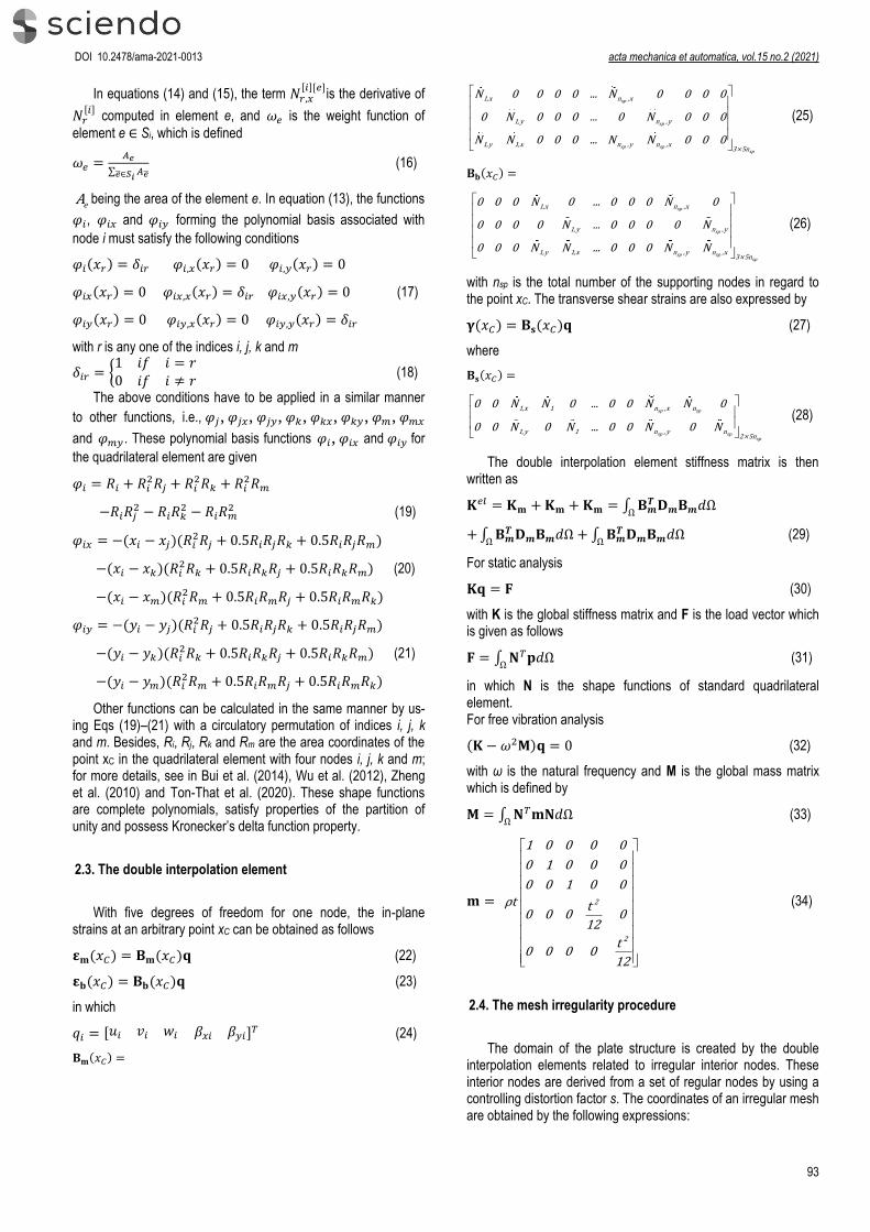
The Cook’s membrane problem is studied in this section with E = 1.0, ν = 0.499 and thickness t = 1, and this model is shown in Fig. 4. Under plane stress conditions, the reference value of the vertical displacement at the centre of the tip section (point C) in Fredriksson et al. (2004) is 23.96. Here, the double interpolation element is compared with other elements listed in Tab. 1 as well as in Fig. 5: Allman’s membrane triangle element (AT) by author
Allman (1984), assumed stress hybrid methods such as P-S element by Pian et al. (1984), HQM/HQ4 element by Xie (2005) and node-based smoothed NSQ4 element by Xuan (2008). Furthermore, the normal stress field will be also plotted in Fig. 4.
DOI 10.2478/ama-2021-0013 acta mechanica et automatica, vol.15 no.2 (2021)
95
Fig. 4. Typical irregular meshes of 8×8 with various distortion factor s
(0.1; 0.2 and 0.3) and the normal stress field
Tab. 1. Results of displacement tip (at C) for Cook’s problem
Element Displacement tip
2x2 4x4 6x6 8x8 10x10
AT 19.67 22.41 – 23.45 –
P-S 21.13 23.02 – 23.69 –
HQM/HQ4 21.35 23.04 – 23.69 –
NSQ4 24.69 25.38 – 24.51 –
Paper (s = 0) 15.24 22.23 23.40 23.76 23.91
Paper (s = 0.1) 14.31 21.87 23.36 23.62 23.90
Paper (s = 0.2) 14.98 22.17 23.39 23.72 23.88
Paper (s = 0.3) 15.34 22.04 23.04 23.75 23.81
Ref (Exact solutiion)
23.96 23.96 23.96 23.96 23.96
AT, Allman’s membrane triangle element, P-S, element based on polynomial stress, HQM/HQ4, hybrid macro element, NSQ4, node-based smoothed element.
Based on the comparison results as below, we can see that (i) when changing the value of s, the results obtained by the
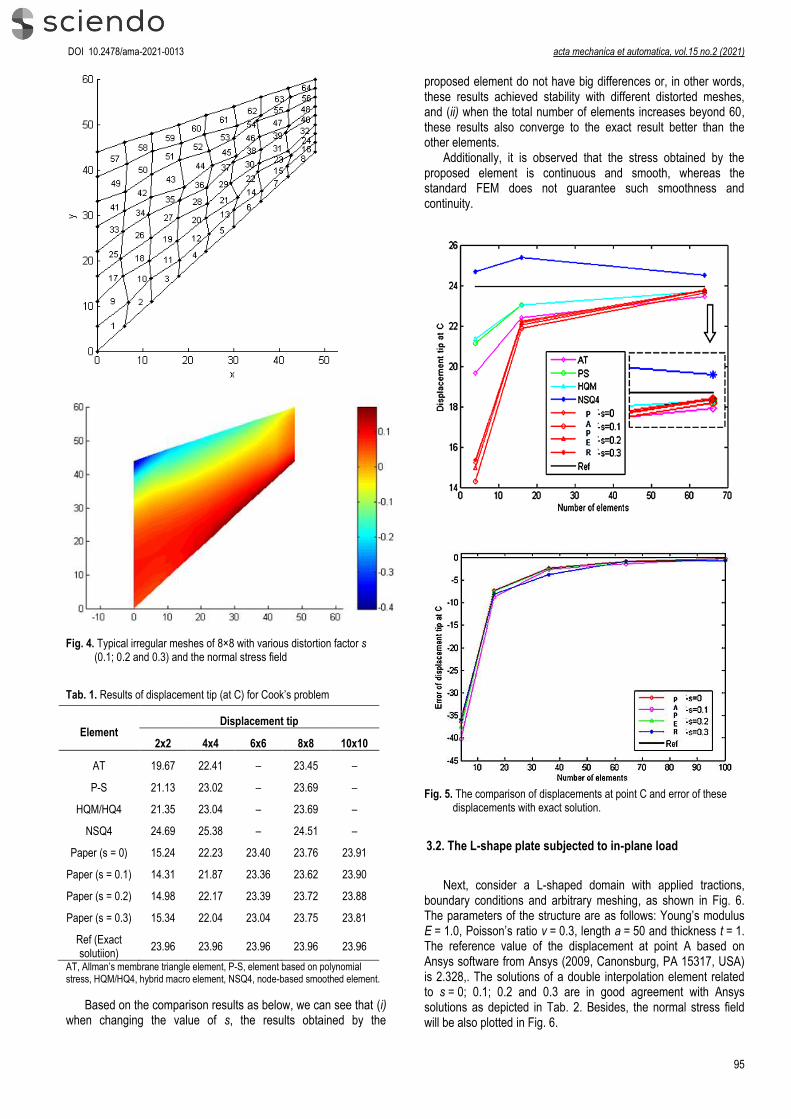
proposed element do not have big differences or, in other words, these results achieved stability with different distorted meshes, and (ii) when the total number of elements increases beyond 60, these results also converge to the exact result better than the other elements.
Additionally, it is observed that the stress obtained by the proposed element is continuous and smooth, whereas the standard FEM does not guarantee such smoothness and continuity.
Fig. 5. The comparison of displacements at point C and error of these
displacements with exact solution.
3.2. The L-shape plate subjected to in-plane load
Next, consider a L-shaped domain with applied tractions, boundary conditions and arbitrary meshing, as shown in Fig. 6. The parameters of the structure are as follows: Young’s modulus E = 1.0, Poisson’s ratio ν = 0.3, length a = 50 and thickness t = 1. The reference value of the displacement at point A based on Ansys software from Ansys (2009, Canonsburg, PA 15317, USA) is 2.328,. The solutions of a double interpolation element related to s = 0; 0.1; 0.2 and 0.3 are in good agreement with Ansys solutions as depicted in Tab. 2. Besides, the normal stress field will be also plotted in Fig. 6.

Hoang Lan Ton-That DOI 10.2478/ama-2021-0013 Plate Structural Analysis Based on a Double Interpolation Element with Arbitrary Meshing
96
Fig. 6. Typical irregular meshes with various distortion factor s (0.1; 0.2
and 0.3) and the normal stress field
Tab. 2. Results of displacement uA at point A for L-shape problems
uA
Paper s = 0
s = 0.1 s = 0.2 s = 0.3 Ansys
2.327 2.323 2.319 2.317 2.328
Error (%)
0.043 0.215 0.386 0.472
Apparently, it is again shown that the normal stress achieved by the proposed element is continuous and smooth through all boundaries of the element.
3.3. The square plate subjected to uniformly distributed and sinusoidal load
The clamped square plate is considered in this section, as shown in Fig. 7.
Fig. 7. A clamped square plate under uniformly distributed load and
sinusoidal load

DOI 10.2478/ama-2021-0013 acta mechanica et automatica, vol.15 no.2 (2021)
97
Following material properties of this isotropic plates are used: E = 210 GPa and ν = 0.3. When subjected to uniformly distributed and sinusoidal load, the author’s result obtained for the central displacement will now be compared and discussed with the corre-sponding results of the exponential shear deformation theory (ESDT) by Sayyad et al. (2012), the higher-order shear defor-mation theory (HSDT) by Reddy (1984), the trigonometric shear deformation theory (TSDT) by Ghugal et al. (2010), the FSDT by Mindlin (1951) and the classical plate theory (CPT) by Kirchhoff (1850), as shown in Tab. 3. The numerical result is presented in the following non-dimensional form w = 100Ew/[qt(a/t)4] and shows good agreement with others.
Tab. 3. Comparison of non-dimensional transverse displacement in an isotropic square plate subjected to uniformly distributed and sinusoidal load
Theory Model (Uniform load)
(Sinusoidal
load)
a/t=4 a/t=10 a/t=4 a/t=10
Sayyad ESDT 5.816 4.658 3.748 2.954
Reddy HSDT 5.869 4.666 3.787 2.961
Ghugal TSDT 5.680 4.625 3.653 2.933
Mindlin FSDT 5.633 4.670 3.626 2.934
Kirchhoff CPT 4.436 4.436 2.803 2.802
Paper (s = 0) FSDT 5.626 4.633 3.782 2.913
Paper (s = 0.1)
FSDT 5.601 4.644 3.771 2.885
Paper (s = 0.2)
FSDT 5.583 4.556 3.734 2.889
CPT, classical plate theory; ESDT, exponential shear deformation theory; FSDT, first-order shear deformation theory; HSDT, higher-order shear deformation theory; TSDT, trigonometric shear deformation theory.
3.4. Free vibration analysis of the square plate
In this last section, author investigates the efficiency of the double interpolation element for analyzing natural frequencies of square plates. The plate has clamped edges with length a and thickness t. The material parameters are E = 2.0 × 10¹¹, ν = 0.3 and ρ = 8000 as follows Nguyen-Xuan et al. (2010). The plate is modeled with 16 elements per each side.
A non-dimensional frequency parameter 𝚟 = (𝜔2𝜌𝑎4𝑡/𝐷)1/4 where 𝐷 = 𝐸𝑡3/(12(1 − 𝜈2)) is often used and then compared to analytical solutions and other numerical results which are available in the literature Nguyen-Xuan et al. (2010) and Robert (1979). Tab. 4 shows the first three values of based on the double interpolation element.
Tab. 4. A non-dimensional frequency parameter of a CCCC square plate
t/a Elements Mode sequence number
1 2 3
0.005 DSG3 6.1786 8.8759 9.0680
ES-DSG3 6.0355 8.6535 8.7081
Paper (s = 0) 5.9861 8.5760 8.5760
Paper (s = 0.1)
5.9933 8.5822 8.5873
Paper (s = 0.2)
6.0182 8.6125 8.6165
Paper (s = 0.3)
6.0331 8.6396 8.6557
Exact 5.9990 8.5680 8.5680
0.1
DSG3 5.7616 7.9935 8.0525
ES-DSG3 5.7250 7.9211 7.9627
Paper (s = 0) 5.7396 7.9787 7.9787
Paper (s = 0.1)
5.7402 7.9802 7.9803
Paper (s = 0.2)
5.7419 7.9822 7.9839
Paper (s = 0.3)
5.7449 7.9879 7.9901
Exact 5.7100 7.8800 7.8800
Fig. 8. Error of the normalized frequencies with t/a = 0.005 and t/a = 0.1

Hoang Lan Ton-That DOI 10.2478/ama-2021-0013 Plate Structural Analysis Based on a Double Interpolation Element with Arbitrary Meshing
98
As shown in Fig. 8 with t/a = 0.005, the double interpolation element is almost better than the DSG3 and ES-DSG3 elements and gives a small error with the exact solution of Robert (1979) for all frequencies examined in this problem. Similarly, in Fig. 8 with t/a = 0.1, the paper’s results are better than the DSG3’s results for all frequencies. Besides, Fig. 9 shows the first mode shapes with the stability of paper’s results related to the small errors.
Mode 1_s = 0 (5.9861)
Mode 1_s = 0.1 (5.9933)
Mode 1_s = 0.2 (6.0182)
Mode 1_s = 0.3 (6.0331)
Fig. 9. The first mode shapes of clamped square plate with t/a = 0.005 and s = 0, 0.1, 0.2 and 0.3
4. CONCLUSION
This paper presented the stability of solutions when using mesh irregularity for structural analysis based on the FEM and the double interpolation elements. Due to the framework of the FSDT and the double interpolation procedure, the double interpolation element becomes an efficient flat quadrilateral element for structural analysis. The shape functions of this element are higher-order polynomials and posses the Kronecker-delta function property, which permits a straightforward imposition of the essential boundary conditions. Moreover, with the influence of neighbouring elements on the element under consideration, the errors will be reduced as well as the results will be stable and less affected by the mesh. Finally, the results obtained in this paper are also compared with other available numerical results to illustrate the robustness of this element as stated above.
REFERENCES
1. Ahmadian H., Faroughi S. (2011a), Development of super-convergent plane stress element formulation using an inverse approach, Finite Elements in Analysis and Design, 47(7), 796-803.
2. Ahmadian H., Faroughi S. (2011b), Shape functions of superconvergent finite element models, Thin-Walled Structures, 49(9), 1178-1183.
3. Allman D. J. (1984), A compatible triangular element including vertex rotations for plane elasticity analysis, Computers and Structures, 19(1), 1-8.
4. Ansys (2009), ANSYS Workbench User’s Guide, ANSYS, Inc.: Canonsburg, PA 15317, USA.
5. Bui T. Q., Vo D. Q., Zhang C., Nguyen D. D. (2014), A consecutive-interpolation quadrilateral element (CQ4): Formulation and applications, Finite Elements in Analysis and Design, 84, 14-31.
6. Chau-Dinh T., Trung-Kien N., Nguyen-Van H., Ton-That H. L. (2021), A MITC3+ element improved by edge-based smoothed strains for analyses of laminated composite plates using the higher-order shear deformation theory, Acta Mechanica, 232(2), 389-422.
7. Da V., Beirao L., Annalisa B., Lovadina C., Martinelli M., Sangalli G. (2012), An isogeometric method for the Reissner Mindlin plate bending problem, Computer Methods in Applied Mechanics and Engineering, 209, 45-53.

DOI 10.2478/ama-2021-0013 acta mechanica et automatica, vol.15 no.2 (2021)
99
8. Devarajan B., Kapania R. K. (2020), Thermal buckling of curvilinearly stiffened laminated composite plates with cutouts using isogeometric analysis, Composite Structures, 238, 111881.
9. Faroughi S., Ahmadian H. (2010), Shape functions associated with inverse element formulations, Proceedings of the Institution of Mechanical Engineers, Part C: Journal of Mechanical Engineering Science, 225(2), 304-311.
10. Fredriksson M., Ottosen N. S. (2004), Fast and accurate 4-node quadrilateral, International Journal for Numerical Methods in Engineering, 61(11), 1809-1834.
11. Ghugal Y. M., Sayyad A. S. (2010), Free vibration of thick orthotropic plates using trigonometric shear deformation theory, Latin American Journal of Solids and Structures, 8, 229-243.
12. Hoang T. T. L. (2020), A new C0 third-order shear deformation theory for the nonlinear free vibration analysis of stiffened functionally graded plates, Facta Universitatis, Series: Mechanical Engineering, Online first.
13. Hoang-Lan T. T. (2020), A Combined Strain Element to Functionally Graded Structures in Thermal Environment, Acta Polytechnica, 60(6), 528-539.
14. Hoang-Lan T. T. (2020), The linear and nonlinear bending analyses of functionally graded carbon nanotube-reinforced composite plates based on the novel four-node quadrilateral element, European Journal of Computational Mechanics, 29(1), 139-172.
15. Hoang-Lan T. T., Nguyen-Van H. (2021), A combined strain element in static, frequency and buckling analyses of laminated composite plates and shells, Periodica Polytechnica Civil Engineering, 65(1), 56-71.
16. Hoang-Lan T. T., Nguyen-Van H., Chau-Dinh T. (2021), A novel quadrilateral element for analysis of functionally graded porous plates/shells reinforced by graphene platelets, Archive of Applied Mechanics.
17. Kirchhoff G. R. (1850), Uber das Gleichgewicht und die Bewegung einer elastischen Scheibe, Journal fur die reine und angewandte Mathematik, 40, 51-88.
18. Miglani J., Devarajan B., Kapania R. K. (2018), Thermal buckling analysis of periodically supported composite beams using Isogeometric analysis, AIAA/ASCE/AHS/ASC Structures, Structural Dynamics, and Materials Conference, 1224.
19. Mindlin R. D. (1951), Influence of rotatory inertia and shear on flexural motions of isotropic, elastic plates, ASME Journal of Applied Mechanics, 18, 31-38.
20. Nguyen-Xuan H., Liu G. R., Thai-Hoang C., Nguyen-Thoi T. (2010), An edge-based smoothed finite element method (ES-FEM) with stabilized discrete shear gap technique for analysis of Reissner–Mindlin plates, Computer Methods in Applied Mechanics and Engineering, 199(9), 471-489.
21. Pian T. H. H., Sumihara K. (1984), Rational approach for assumed stress finite elements, International Journal for Numerical Methods in Engineering, 20(9), 1685-1695.
22. Reddy J. N. (1984), A simple higher-order theory for laminated composite plates, Journal of Applied Mechanics, 51(4), 745-752.
23. Reddy J. N. (2007), Theory and Analysis of Elastic Plates and Shells: CRC Press.
24. Robert D. B. (1979), Formulas for natural frequency and mode shape, New York: Van Nostrand Reinhold.
25. Sayyad A. S., Ghugal Y. M. (2012), Bending and free vibration analysis of thick isotropic plates by using exponential shear deformation theory, Applied and Computational Mechanics, 6(1), 65-82.
26. Ton T. H. L. (2019), Finite element analysis of functionally graded skew plates in thermal environment based on the new third-order shear deformation theory, Journal of Applied and Computational Mechanics, 6(4), 1044-1057.
27. Ton T. H. L. (2020), A novel quadrilateral element for dynamic response of plate structures subjected to blast loading, Journal of Applied and Computational Mechanics, 6, 1314-1323.
28. Ton T. H. L. (2020), Improvement on eight-node quadrilateral element (IQ8) using twice-interpolation strategy for linear elastic fracture mechanics, Engineering Solid Mechanics, 8(4), 323-336.
29. Ton-That H. L., Nguyen-Van H., Chau-Dinh T. (2020), Nonlinear Bending Analysis of Functionally Graded Plates Using SQ4T Elements based on Twice Interpolation Strategy, Journal of Applied and Computational Mechanics, 6(1), 125-136.
30. Ton-That H. L., Nguyen-Van H., Chau-Dinh T. (2020), Static and buckling analyses of stiffened plate/shell structures using the quadrilateral element SQ4C, Comptes Rendus. Mécanique, 348(4), 285-305.
31. Tran L. V., Wahab M. A., Seung-Eock K. (2017), An isogeometric finite element approach for thermal bending and buckling analyses of laminated composite plates, Composite Structures, 179, 35-49.
32. Wu S. C., Zhang W. H., Peng X., Miao B. R. (2012), A twice-interpolation finite element method (TFEM) for crack propagation problems, International Journal of Computational Methods, 9(4), 1250055.
33. Xie X. P. (2005), An accurate hybrid macro-element with linear displacements, Communications in Numerical Methods in Engineering, 21(1), 1-12.
34. Xuan H. N. (2008), A strain smoothing method in finite elements for structural analysis, PhD thesis, University of Liege, Belgium.
35. Zheng C., Wu S. C., Tang X. H., Zhang J. H. (2010), A novel twice-interpolation finite element method for solid mechanics problems, Acta Mechanica Sinica, 26(2), 265-278.