plate heat exchangers - cooke industries · pdf fileplate heat exchangers 040217 auckland...
TRANSCRIPT
Plate heat exchangers
040217
Auckland (Head Office) Christchurch 31 Station Road, Penrose, Auckland, NZ Level 3, 161 Kilmore Street, Christchurch, NZ PO Box 12021, Penrose, Auckland 1135 PO Box 17709, Sumner, Christchurch 8008 Ph: +64-9-579 2185 Fax: +64-9-579 2181 Ph: +64-3-379 7884 Fax: +64-3-379 7874
Web: www.cookeindustries.co.nz Email: [email protected]

ContentsIntroduction 1
Quality 2
Examples of Applications 3
Product Code 4
Technical Features 5
Differential Pressure 7
Options 8
Specific Applications 10
Dimensions 11
Instructions 19
Selection 23
Customer References 27
Auckland (Head Office) Christchurch 31 Station Road, Penrose, Auckland, NZ Level 3, 161 Kilmore Street, Christchurch, NZ PO Box 12021, Penrose, Auckland 1135 PO Box 17709, Sumner, Christchurch 8008 Ph: +64-9-579 2185 Fax: +64-9-579 2181 Ph: +64-3-379 7884 Fax: +64-3-379 7874
Web: www.cookeindustries.co.nz Email: [email protected]

1
Energy Saving.Recuperator heat recovery units offervarious possibilities for energy savingand an alternative for reducing energycosts and atmospheric pollution.
Characteristics.Heat-exchangers are exchangers thatenable heat to be transferred betweenthe input and the output air-flows basedon the difference in temperature.Recuperator offer two series of staticplate exchangers (Series B and F) anda rotary exchanger series (Series T),whose characteristics meet the require-ments of both the industrial and thenon-industrial markets.
Reliability and High Performance.The plate type are air-to-air heat-exchangers that have no moving parts,offering very high reliability andperformance; in addition, they make forlow energy consumption in associatedboiler equipment.The heat is transmitted directly from thehigher to the lower temperature-flow;the air-flow pattern is of cross-flowdesign, and the exchanger's efficiencyis between 40 and 75%.
Sealing.This type of heat-exchanger consists offlat plates with swirl control, whosespacing depends on the type ofapplication.The exhaust and supply air-flows arecompletely separated by means ofspecial seals.
Materials.The plates are usually made ofaluminium, due to the latter's corrosion-resistance, ease of manufacture, non-inflammability, and durability. In specialcases, such as the presence ofcorrosive parts, the aluminium can becoated with anti-corrosion paint, while,in the case of high operatingtemperatures or special applications,stainless steel alloys are used.
Condensation.Plate-type exchangers do not allow forthe passage of humidity from one flowto another, but can transfer part of thelatent heat contained in the wetexhaust air-flow; this happensespecially when external temperaturesare very low, so that the supply aircools the wet exhaust below its dewpoint and condensation is formed.
Introduction

2
It is Recuperator's constant aim tomaintain the highest standards ofquality. Stated performance figures arecertified by tests carried out inaccordance with Eurovent rules byindependent organizations such asTechnikum of Lucerne (Switzerland)and Istituto Ricerche e Collaudi Masiniof Rho (Milan).The quality and performance ofRecuperator products are guaranteedby a well-equipped research laboratoryand an ASHRAE wind-tunnel, wheretests are conducted periodically onproduct lines.
All supplies of aluminium coils arechecked and tested using our Erichsentest equipment, in accordance with DINStandard 50 101. Checks are repeatedduring and at the end of themanufacturing process so that thephysical characteristics of the materialsused are continuously monitored.
Quality

Air-conditioningVentilation
Areas
Schools
Swimming-pools
Hospitals
Telephony
Railways
Ventilation hoods
Dryers
Rotogravure printing machines
Heat recovery from flue gases
3
MaterialSeries
The table gives a few examples ofapplications relating to series andmaterials used by Recuperator.
Pre-heating and pre-cooling in the air-handling units
ApplicationBF
Aluminium
Heat recovery from air renewal (B Aluminium)B Aluminium
Pre-heating of air in air-handling unitsBF
Coated aluminium
Heat recovery from the exhaust air withoutmixing of the two air-flows
BF
Aluminium and stainless-steel
Heat dissipation inside shelters and mobiletelephone cabins
B B Aluminium and coated aluminium
Heat dissipation inside converters for air-conditioning in railway carriages
BF
Aluminium
Heat recovery from flue gases for heatingpremises
BF
B Aluminium and coated aluminium
Pre-heating of air inside dryers and heating ofpremises
BF
Aluminium and stainless-steel
Heat recovery from solvents and heating ofpremises
BF
Aluminium and stainless-steel
Heat recovery for pre-heating the air at entranceto burners and heating of premises
BF
Stainless steel
Examples of Applications
4
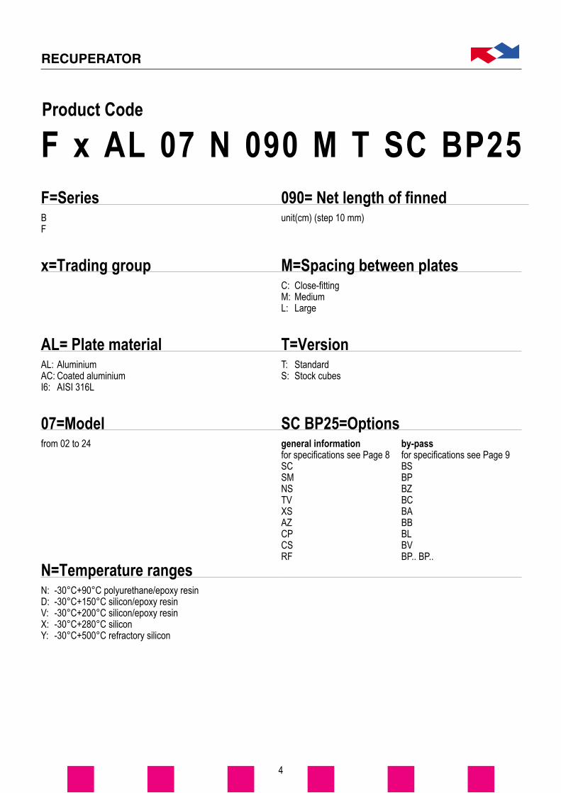
07=Modelfrom 02 to 24
AL= Plate materialAL: AluminiumAC: Coated aluminiumI6: AISI 316L
N=Temperature rangesN: -30°C+90°C polyurethane/epoxy resinD: -30°C+150°C silicon/epoxy resinV: -30°C+200°C silicon/epoxy resinX: -30°C+280°C siliconY: -30°C+500°C refractory silicon
F=SeriesBF
x=Trading group
T=VersionT: StandardS: Stock cubes
SC BP25=Options
090= Net length of finned unit(cm) (step 10 mm)
M=Spacing between platesC: Close-fittingM: MediumL: Large
Product Code
F x AL 07 N 090 M T SC BP25
general informationfor specifications see Page 8SCSMNSTVXSAZCPCSRF
by-passfor specifications see Page 9BSBPBZBCBABBBLBVBP.. BP..
5
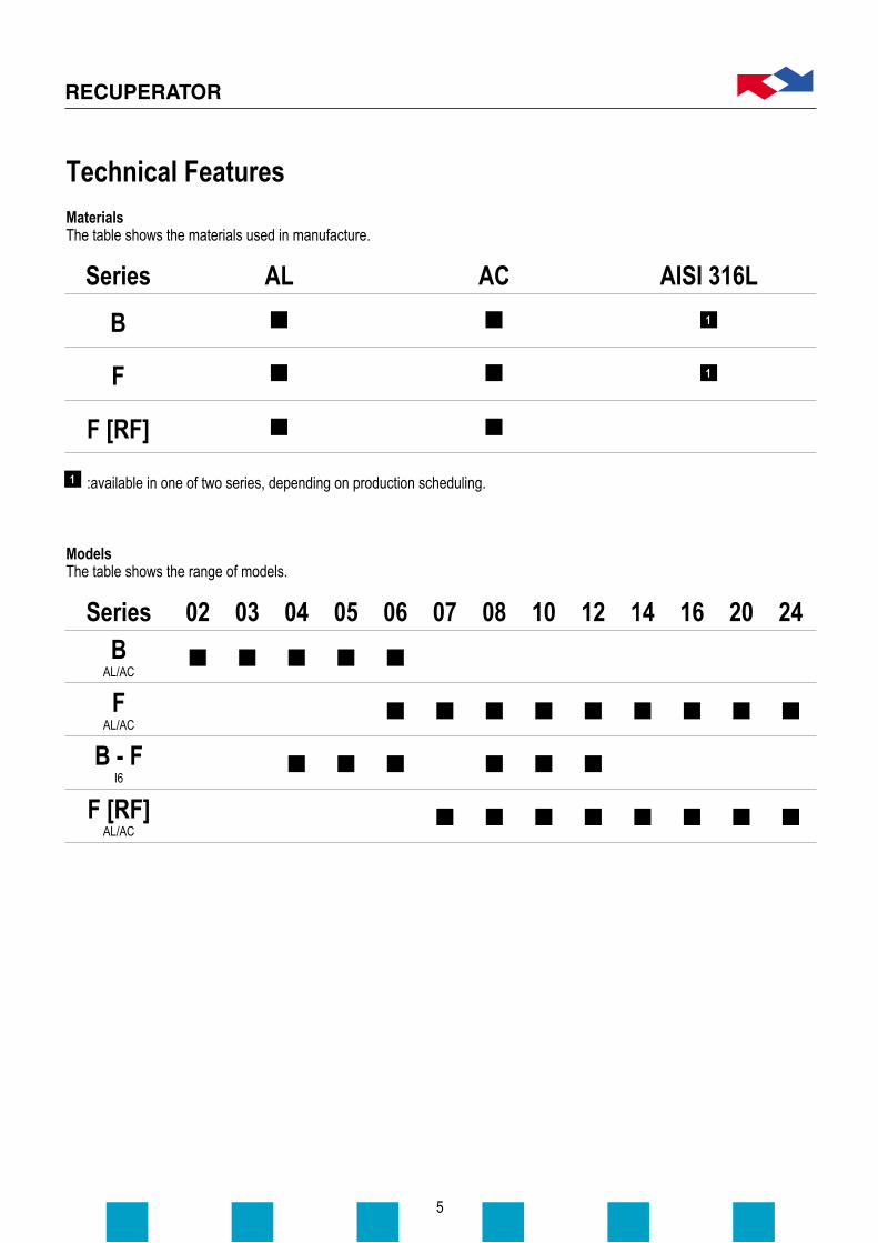
MaterialsThe table shows the materials used in manufacture.
ModelsThe table shows the range of models.
AL AC AISI 316L
F [RF]
F
B
Series
B - F I6
FAL/AC
F [RF]AL/AC
BAL/AC
Series 02 03 04 05 06 07 08 10 12 14 16 20 24
Technical Features
:available in one of two series, depending on production scheduling.
1
1
1

6
TemperatureFive temperature ranges are available.
: in Version Y, sealing between the two flows is not guaranteed
N-30°C÷90°C
B - F I6
FAL/AC
BAL/AC
Series
P
P
P
R
R
D-30°C÷150°C
S
S
S
R
R
V-30°C÷200°C
S
X-30°C÷280°C
S
Y-30°C÷500°C
1 F
1
: polyurethane PP
: silicone SS
: resin RR
: refractory silicon FF
SpacingPlate spacing availability.
C M L
B - F I6
FAL/AC
BAL/AC
Series

7
Model
Model
B-F stainless steelThe table gives the maximum differential pressures allowed for Series B and F in stainless steel.
B AluminiumFor all the models in Series B the maximum differential pressure between supply and exhaust flow rate is 1000 Pa for platespacing C, and 1500 Pa for plate spacings M and L.
F AluminiumThe table shows the maximum differential pressures for Series F in aluminium.
04
: 2000 Pa
: 2500 Pa
: 1500 Pa
: 1700 Pa
A
B
C
D
For version XS (Series F only) themaximum differential pressure is 4500Pa.
For version XS the maximumdifferential pressure is 2500 Pa.
L
M
C
Spacing
B
A
B
B
A
B
B
B
B
B
B
B
B
B
B
B
B
B
B
B
B
B
B
B
B
B
B
06 07 08 10 12 14 16 20 24
M
Spacing
C
05C
06C
08D
10D
12D
Differential Pressure

XSGreater resistance to differentialpressure.
TVThe frame is coated when the heat-exchanger frame is exposed corrosivesubstances.
8
Recuperator offers a series of options for differing requirements.
:standard version for Series B
BAL/AC
FAL/AC
BI6
FI6
XS TV AZ SM SC CP NSSeries
CPTop cover with bevelled corners toreduce the diagonal dimension.
NSVersion using other sealants instead ofsilicon. Available for temperatures of upto 90°C (temperature range “N”).
AZSide in thinner aluminium.
RFReinforced frame for lager, heavierheat-exchangers.
SCExtra sealing to ensure closer fit of thetwo air-flows (example: application forhospitals). A leakage diagram can behad on request in this version.
SMMechanical sealing of the exchangerunit. A leakage diagram in this versioncan be had on request.
CSSpecial corner sections to makediagonal fitting easier.
4
2
2
1
3
1 3
CS RF
:standard version for Series F2
:standard version for models02 and 03
4
1 :not available for the “Y” temperature range
3
Options
CS Option CP Option (B series) CP Option (F series)
9
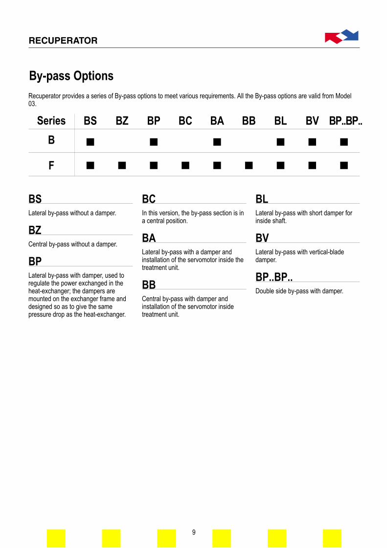
BPLateral by-pass with damper, used toregulate the power exchanged in theheat-exchanger; the dampers aremounted on the exchanger frame anddesigned so as to give the samepressure drop as the heat-exchanger.
BSLateral by-pass without a damper.
BCIn this version, the by-pass section is ina central position.
BZCentral by-pass without a damper. BA
Lateral by-pass with a damper andinstallation of the servomotor inside thetreatment unit.
BLLateral by-pass with short damper forinside shaft.
BBCentral by-pass with damper andinstallation of the servomotor insidetreatment unit.
BVLateral by-pass with vertical-bladedamper.
BP..BP..Double side by-pass with damper.
B
F
BS BZ BP BC BB BL BV BP..BP..Series
Recuperator provides a series of By-pass options to meet various requirements. All the By-pass options are valid from Model03.
BA
By-pass Options

10
The air-flow direction is of no real importance. However, it is recommended that the exhaust air pass through the heat-exchanger from the top towards the bottom in cases in which the formation of condensation is to be expected.
Some examples of the behaviour of the two air-flows, using a single heat-exchanger.In special cases, it is possible to use several heat-exchangers to overcome inconveniences such as: lack of space, a majordifference between the two flows, etc. The drawings show a few examples.
Special Applications

11
07081012
Aluminium and coated aluminium
General tolerances: UNI ISO 2768 – c
Series BModel
0203040506
Amm
Max 700Max 900
Max 1200Max 1300Max 1400
A1mm
A+2CA+2CA+2CA+2CA+2C
Bmm140240340440540
B1mm200300400500600
Cmm2020202020
Dmm3030303030
Series F[RF]Model
AL/A
C
Amm
Max 3000Max 3000Max 3000Max 3000
A1mm
A+2CA+2CA+2CA+2C
Bmm6407409401140
B1mm74084010401240
Cmm50505050
Dmm50505050
NB: Option PV:A = max 500 mmOption AZ:A = max 700 mm
AL/A
C
0607081012
Series FModel
Amm
Max 1500Max 2400Max 2400Max 2400Max 2400
A1mm
A+2CA+2CA+2CA+2CA+2C
Bmm5196197199191119
B1mm60570580510051205
Cmm2030304040
Dmm4343434343
AL/A
C
Dimensions
NB: Option CP: A = max 1700 mm

12
Aluminium and coated aluminium
Series FModel
14162024
Amm
Max 2400Max 2400Max 2400Max 2400
A1mm
A+2CA+2CA+2CA+2C
Bmm6197199191119
B1mm
1410161020102410
Cmm30304040
Dmm43434343
Series F[RF]Model14162024
Amm
Max 3000Max 3000Max 3000Max 3000
A1mm
A+2CA+2CA+2CA+2C
Bmm6407409401140
B1mm
1480168020802480
Cmm50505050
Dmm50505050
General tolerances: UNI ISO 2768 – c
AL/A
CAL
/AC
Nota: opzione CP: A = max 1700 mm

NB: * = Min 100 - Max 999
NB: Option CP: A = max 1300 mm
* = Min 100 - Max 999
** = Max 2800 mm
NB: * = Min 100 - Max 999
03040506
13
Aluminium and coated aluminium – By-pass without a damper
Series F[RF]Model07081012
Amm
Max 3000Max 3000Max 3000Max 3000
A1mm
A+2CA+2CA+2CA+2C
Bmm640740940
1140
B1mm74084010401240
Cmm50505050
Dmm50505050
Fmm
A1+L+CA1+L+CA1+L+CA1+L+C
Lmm
****
Series FModel
0607081012
Amm
Max 1500Max 2400Max 2400Max 2400Max 2400
A1mm
A+2CA+2CA+2CA+2CA+2C
Bmm519619719919
1119
B1mm60570580510051205
Cmm2030304040
Dmm4343434343
F **mm
A1+L+CA1+L+CA1+L+CA1+L+CA1+L+C
Lmm
*****
Dmm30303030
Fmm
A1+L+CA1+L+CA1+L+CA1+L+C
Lmm
****
Series BModel
Amm
Max 900Max 1200Max 1200Max 1200
A1mm
A+2CA+2CA+2CA+2C
Bmm240340440540
B1mm300400500600
Cmm20202020
General tolerances: UNI ISO 2768 – c
AL/A
CAL
/AC
AL/A
C
Dimensions

14
Aluminium and coated aluminium – By-pass with a damper
Series F[RF]Model14162024
Amm
Max 3000Max 3000Max 3000Max 3000
A1mm
A+C+C1A+C+C1A+C+C1A+C+C1
Bmm640740940
1140
B1mm
1480168020802480
Cmm50505050
C1mm50505050
Dmm50505050
Fmm
A1+L+CA1+L+CA1+L+CA1+L+C
Lmm
****
Series FModel
14162024
Amm
Max 2400Max 2400Max 2400Max 2400
A1mm
A+C+C1A+C+C1A+C+C1A+C+C1
Bmm619719919
1119
B1mm
1410161020102410
Cmm30304040
C1mm30304040
Dmm43434343
F **mm
A1+L+CA1+L+CA1+L+CA1+L+C
Lmm
****
General tolerances: UNI ISO 2768 – c
AL/A
CAL
/AC
NB: Option CP: A = max 1300 mm
* = Min 100 - Max 999
** = Max 2800 mm
NB: * = Min 100 - Max 999

15
Aluminium and coated aluminium – By-pass with a damper
Series BModel
03040506
Amm
Max 900Max 1200Max 1200Max 1200
A1mm
A+2CA+2CA+2CA+2C
Bmm240340440540
B1mm300400500600
B2mm425525625725
B3mm210310410510
Cmm20202020
Dmm30303030
Fmm
A1+L+CA1+L+CA1+L+CA1+L+C
Gmm95200200300
Lmm
Min 100Min 100Min 100Min 100
Tmm35353535
Vmm125125125125
Wmm25252525
Series F[RF]Model07081012
Amm
Max 3000Max 3000Max 3000Max 3000
A1mm
A+2CA+2CA+2CA+2C
Bmm640740940
1140
B1mm740840
10401240
B2mm87097011701370
B3mm6107109101110
Cmm50505050
Dmm50505050
Fmm
A1+L+CA1+L+CA1+L+CA1+L+C
Gmm370420520620
Lmm
Min 100Min 100Min 100Min 100
Tmm40404040
Vmm125125125125
Wmm40404040
Series FModel
0607081012
Amm
Max 1500Max 2400Max 2400Max 2400Max 2400
A1mm
A+2CA+2CA+2CA+2CA+2C
Bmm519619719919
1119
B1mm605705805
10051205
B2mm73083093011301330
B3mm5106107109101110
Cmm2030304040
Dmm4343434343
F **mm
A1+L+CA1+L+CA1+L+CA1+L+CA1+L+C
Gmm302302402502602
Lmm
Min 100Min 100Min 100Min 100Min 100
Tmm3535353535
Vmm125125125125125
Wmm2525252525
General tolerances: UNI ISO 2768 – c
AL/A
CAL
/AC
AL/A
C
Dimensions
NB: Option CP: A = max 1300 mm
** = Max 2800 mm

16
Aluminium and coated aluminium – By-pass with a damper
Series F[RF]Model07081012
Amm
Max 1500Max 1500Max 1500Max 1500
Bmm6407409401140
B1mm74084010401240
B2mm87097011701370
B3mm6107109101110
Cmm50505050
Dmm50505050
Gmm370420520620
Fmm
2A+L+4C2A+L+4C2A+L+4C2A+L+4C
Lmm
****
Tmm40404040
Vmm125125125125
Wmm40404040
Series FModel
07081012
Amm
Max 750Max 750Max 750Max 750
Bmm6197199191119
B1mm70580510051205
B2mm83093011301330
B3mm6107109101110
Cmm30304040
Dmm43434343
Gmm302402502602
F **mm
2A+L+4C2A+L+4C2A+L+4C2A+L+4C
Lmm
****
Tmm35353535
Vmm125125125125
Wmm25252525
General tolerances: UNI ISO 2768 – c
AL/A
CAL
/AC
Dimensions
NB: Option CP: A = max 1300 mm
* = Min 100 - Max 999, ** = Max 2100 mm
NB: * = Min 100 - Max 999

17
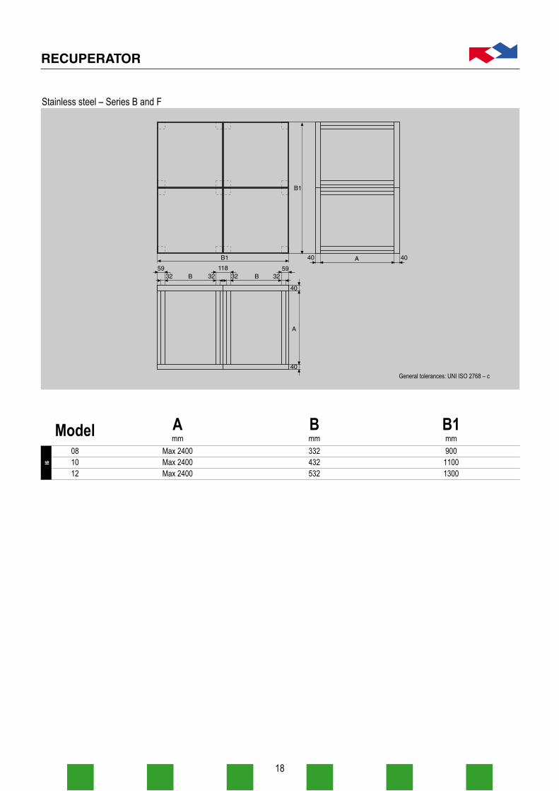
Stainless steel – Series B and F
Model040506
Amm
Max 2400Max 2400Max 2400
Bmm332432532
B1mm450550650
General tolerances: UNI ISO 2768 – c
I6
Dimensions
18
Stainless steel – Series B and F
Model081012
Amm
Max 2400Max 2400Max 2400
Bmm332432532
B1mm90011001300
General tolerances: UNI ISO 2768 – c
I6

19
Instructions on transport and assemblyof Series B and F.
Packaging.The packaging of Series F consists of apallet-type base and three woodenpanels fitted on the equipment with astrap.For Model 06 and for finned lengths notexceeding 1200 mm, packagingconsists of special triple-corrugatedcardboard.Packaging for Series B consists of thesame type of special corrugatedcardboard.
Preliminary Inspection.Before removing the packaging it isadvisable to check that the heat-exchanger has not been damaged intransit; careful visual checking shouldbe enough to ensure that thepackaging is in good condition. Itshould not be removed until the timecomes to connect the heat-exchangerto the air-ducts or install it in the air-treatment units, thus avoiding anysoiling or damage of any kind.When starting up the plant, care shouldbe taken to avoid "water hammering"which could cause a higher differential
pressure than that allowed, withpossible damage to the heat recoveryunit. Care should also be taken to avoidforeign matter (rubble, paper, etc.)being sucked into the system. It istherefore recommended that the air-ducts be cleaned before installation, ora temporary by-pass around the unitset up, or provisional filters be fitted.
Installation.The heat-exchanger may be installed inair-ducts, or else inside an air-handlingunit. It is important that the platesshould be set vertically, to facilitate thedraining of condensation. In the air-handling units, the heat recovery unit islodged on proper slides and the sealson supports (see Fig. 1), made easierby the use of rubber weather bands.
1
Instructions – Aluminium Version
20
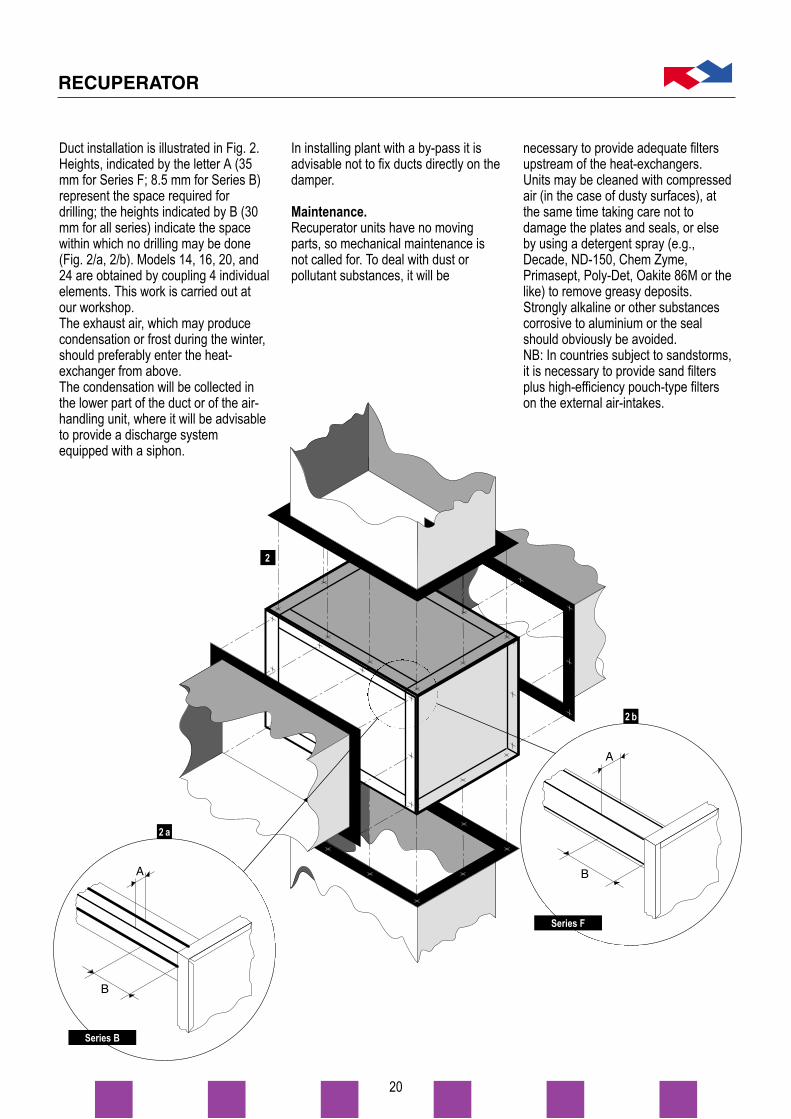
Duct installation is illustrated in Fig. 2.Heights, indicated by the letter A (35mm for Series F; 8.5 mm for Series B)represent the space required fordrilling; the heights indicated by B (30mm for all series) indicate the spacewithin which no drilling may be done(Fig. 2/a, 2/b). Models 14, 16, 20, and24 are obtained by coupling 4 individualelements. This work is carried out atour workshop.The exhaust air, which may producecondensation or frost during the winter,should preferably enter the heat-exchanger from above.The condensation will be collected inthe lower part of the duct or of the air-handling unit, where it will be advisableto provide a discharge systemequipped with a siphon.
In installing plant with a by-pass it isadvisable not to fix ducts directly on thedamper.
Maintenance.Recuperator units have no movingparts, so mechanical maintenance isnot called for. To deal with dust orpollutant substances, it will be
necessary to provide adequate filtersupstream of the heat-exchangers.Units may be cleaned with compressedair (in the case of dusty surfaces), atthe same time taking care not todamage the plates and seals, or elseby using a detergent spray (e.g.,Decade, ND-150, Chem Zyme,Primasept, Poly-Det, Oakite 86M or thelike) to remove greasy deposits.Strongly alkaline or other substancescorrosive to aluminium or the sealshould obviously be avoided.NB: In countries subject to sandstorms,it is necessary to provide sand filtersplus high-efficiency pouch-type filterson the external air-intakes.
2
2 a
Series B
Series F
2 b

21
Instructions on transport and assemblyof Series B and F.
Packaging.The packaging of Series B and Fconsists of a pallet-type base and threewooden panels fitted on the equipmentwith a strap.
Preliminary Inspection.Before removing the packaging it isadvisable to check that the heat-exchanger has not been damaged intransit; careful visual checking shouldbe enough to ensure that thepackaging is in good condition. Itshould not be removed until the timecomes to connect the heat-exchangerto the air-ducts or install it in the air-treatment units, thus avoiding anysoiling or damage of any kind.When starting up the plant, care should
be taken to avoid "water hammering"which could cause a higher differentialpressure than that allowed, withpossible damage to the heat recoveryunit. Care should also be taken to avoidforeign matter (rubble, paper, etc.)being sucked into the system. It istherefore recommended that the air-ducts be cleaned before installation, ora temporary by-pass around the unitset up, or provisional filters be fitted.
Installation.The heat-exchanger may be installed inair-ducts, or else inside an air-handlingunit. It is important that the platesshould be set vertically, to facilitate thedraining of condensation. In the air-handling units, the heat recovery unit islodged on proper slides and the sealson supports (see Fig. 1), made easierby the use of rubber weather bands.Duct installation is illustrated in Fig.s 2and 3.
12 3
Instructions – Stainless Steel Version

22
The holes drilled in the sections andsides of the four corners have to bemade by the customer. The ducts areheld together with through-screws,fastened with nuts and bolts (shown indetail in Figs. 4 and 5).Models 08, 10, and 12 are obtained bycombining four individual components(Models 04, 05, 06). For efficientsealing, a gasket between the flangesis recommended.The exhaust air, which may producecondensation or frost during the winter,should preferably enter the heat-exchanger from above.The condensation will be collected inthe lower part of the duct or of the air-handling unit, where it will be advisable
to provide a discharge systemequipped with a siphon.
Maintenance.Recuperator units have no movingparts, so mechanical maintenance isnot called for. To deal with dust orpollutant substances, it will benecessary to provide adequate filtersupstream of the heat-exchangers.Units may be cleaned with compressedair (in the case of dusty surfaces), atthe same time taking care not todamage the plates and seals, or elseby using a detergent spray (e.g.,Decade, ND-150, Chem Zyme,Primasept, Poly-Det, Oakite 86M or thelike) to remove greasy deposits.
Strongly alkaline or other substancescorrosive to aluminium or the sealshould obviously be avoided.NB: In countries subject to sandstorms,it is necessary to provide sand filtersplus high-efficiency pouch-type filterson the external air-intakes.
4
5
M10 screws
Sealinggasket
M8 screws
Sealinggasket
5
M8 screws
Sealinggasket
Series B
Series F

23
Recuperator supplies its customers withthe REX program (RecuperatorExchangers). This enables customersto select the best heat-exchanger, sinceit contains a price-list and all thenecessary technical information.
Selection
24
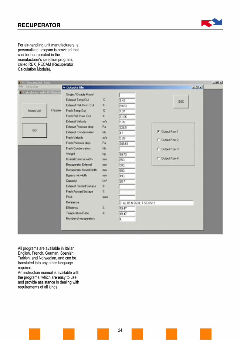
For air-handling unit manufacturers, apersonalized program is provided thatcan be incorporated in themanufacturer's selection program,called REX_RECAM (RecuperatorCalculation Module).
All programs are available in Italian,English, French, German, Spanish,Turkish, and Norwegian, and can betranslated into any other languagerequired.An instruction manual is available withthe programs, which are easy to useand provide assistance in dealing withrequirements of all kinds.
25
80Pa
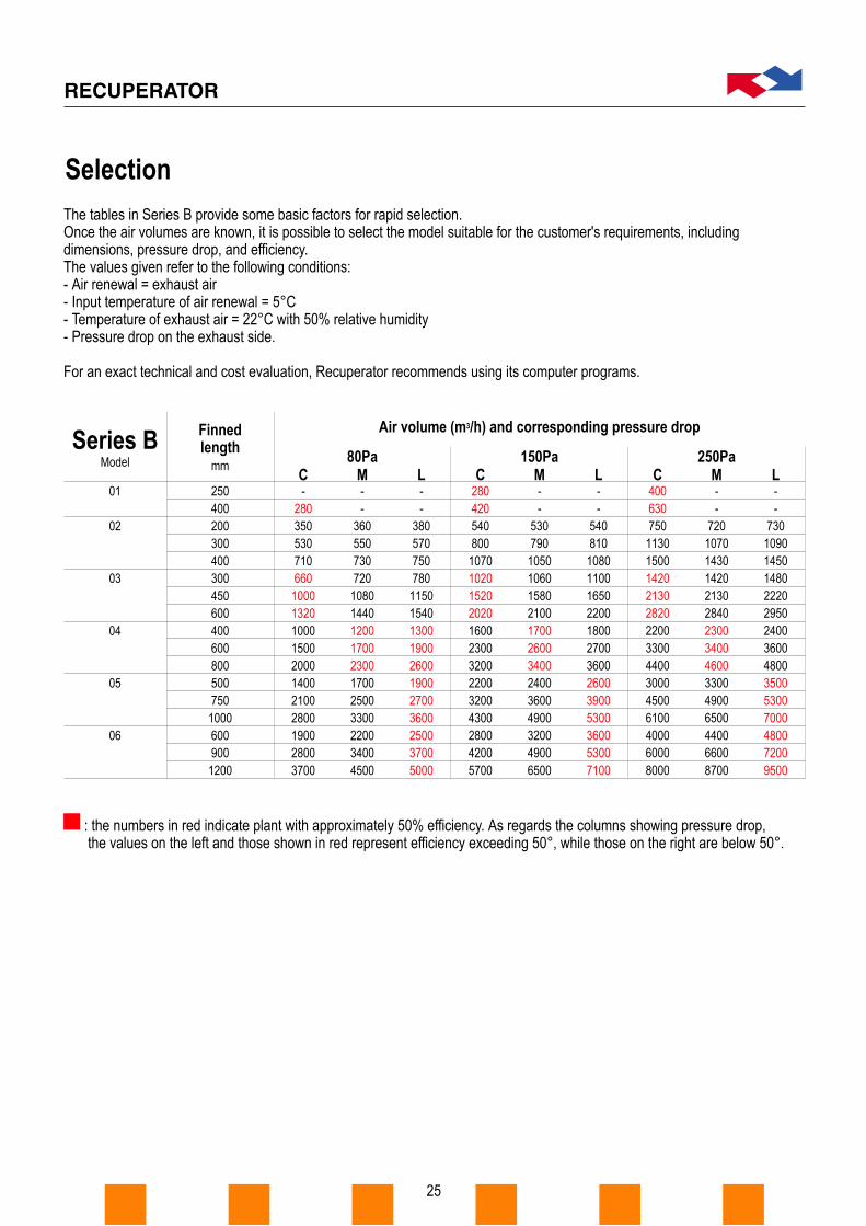
The tables in Series B provide some basic factors for rapid selection.Once the air volumes are known, it is possible to select the model suitable for the customer's requirements, includingdimensions, pressure drop, and efficiency.The values given refer to the following conditions:- Air renewal = exhaust air- Input temperature of air renewal = 5°C- Temperature of exhaust air = 22°C with 50% relative humidity- Pressure drop on the exhaust side.
For an exact technical and cost evaluation, Recuperator recommends using its computer programs.
: the numbers in red indicate plant with approximately 50% efficiency. As regards the columns showing pressure drop,the values on the left and those shown in red represent efficiency exceeding 50°, while those on the right are below 50°.
Series BModel
01
02
03
04
05
06
250400200300400300450600400600800500750
1000600900
1200
C M L C M L C M L
Air volume (m3/h) and corresponding pressure drop
150Pa 250Pa
-280350530710660
10001320100015002000140021002800190028003700
--
360550730720
10801440120017002300170025003300220034004500
--
38057075078011501540130019002600190027003600250037005000
2804205408001070102015202020160023003200220032004300280042005700
--
5307901050106015802100170026003400240036004900320049006500
--
5408101080110016502200180027003600260039005300360053007100
40063075011301500142021302820220033004400300045006100400060008000
--
72010701430142021302840230034004600330049006500440066008700
--
73010901450148022202950240036004800350053007000480072009500
Finnedlength
mm
Selection

26
100Pa
06
07
08
10
12
14
16
20
24
600900
1200700
10501400800
1200160010001500200012001800240014002100240016002400200024002400
The tables in Series B provide some basic factors for rapid selection.Once the air volumes are known, it is possible to select the model suitable for the customer's requirements, includingdimensions, pressure drop, and efficiency.The values given refer to the following conditions:- Air renewal = exhaust air- Input temperature of air renewal = 5°C- Temperature of exhaust air = 22°C with 50% relative humidity- Pressure drop on the exhaust side.
For an exact technical and cost evaluation, Recuperator recommends using its computer programs.
: the numbers in red indicate plant with approximately 50% efficiency. As regards the columns showing pressure drop,the values on the left and those shown in red represent efficiency exceeding 50°, while those on the right are below 50°.
Series FModel
C M L C M L C M L
Air volume (m3/h) and corresponding pressure drop
200Pa 300Pa
32004800640041006200830058008600
114009200
13800184001400021000280001550023000265002150033000320003900045000
35005200700045006800910063009400
125001020015300204001570023700314001700025000290002300035000345004200049000
380058007700490074009900690010400138001120016800223001710025700343001800027000310002450037000370004500053000
4700700094006100910012100840012600169001370020600274002090031200420002300034000390003150047000475005700066000
520077001080067001000013400930013900185001510022700304002320034800464002500037000420003400051000520006200073000
5600850011200730011000146001020015200203001660024800331002510037700503002700040000450003600054000550006700079000
5900890011800770011500153001060015900210001720025800344002620039850523002900043000490004000060000600007200083000
6500970012900840012700168001170017500233001900028500381002910043700580003150047000530004300064000650007800091000
70001050014009200130001840012800191002550020800314004180031700476006330034000500005700045000680007000083000100000
Finnedlength
mm

LepetitIndustria farmaceutica - Svizzera
CariploBanca - Italia
LinateAereoporto - Italia
27
Recuperator is able to offer itscustomers a disk and a book, coveringthe first ten years of its activity (1975-1985), containing a few thousandcustomer references from all over theworld.
FIATAutomobili - Italia
CarrierCondizionamento - USA - Francia
General MotorsAutomobili - USA
LuxotticaIndustria ottica - Italia
BBCRete televisiva - UK
ComprintMacchine da stampa - Australia
Nuova BicoccaUniversità di Milano - Italia
BayerIndustria farmaceutica - Italia
NovotelCatena alberghiera internazionale
Customer References
Italtel-TelecomTelecomunicazioni - Italia
EnelIndustria elettrica - Italia
PirelliPneumatici - Italia
Magneti MarelliIndustria elettronica - Italia
RicordiIndustria discografica - Italia
San PaoloBanca - Italia

Recuperator srl - via Mantova 4 - 20020 Lainate (MI) Italia - tel. ++39 02 93 79 21 1 - fax ++39 02 93 57 27 24recuperator@recuperator .net - www.recuperator .net
A4 Torino-Trieste
Arluno exit
via dell’Artigianato
RECUPERATOR(n.15)
Ossona cemetery
Iveco-Lanciadealer
Recuperator sign board
directionCastano - InverunoRecuperator sign board
Zazzeranursery garden
dealer
Recuperator sign board
Lainateexit
via Comovia Nerviano
A8 Milano Laghi
via Rhovia Nerviano
via Sondrio
via Mantova
RECUPERATOR(n.4)
via Sondrio
directionNerviano
industrialestate
directionInveruno
stop
Auchanshopping centre
via MantovaLainate
RECUPERATOR(n.4)
Iveco-Lanciadealer
Zazzeranursery garden
viadell’Artigianato
InverunoRECUPERATOR(n.15)
From A8 Motorway, to Milan and the LakesLainate office
From A4 Motorway, to Turin and TriesteInveruno office
From Lainate to Inveruno