plate bearing
DESCRIPTION
Plate BearingTRANSCRIPT

PLATE BEARING TEST
TEST DETAILS AND REPORT FROM SITE VISIT
on 12 February 2014
Alan Ting

This paper presents details of a plate bearing test and report from a site visit in Kuching, Malaysia.
Technical details of a plate bearing test will be presented, including standards and procedures
concerned. A sample method statement will also be discussed. Photos and results from a site visit
will conclude the paper.

Contents TECHNICAL DETAILS ................................................................................................................................ 1
Introduction ........................................................................................................................................ 1
Frequency ........................................................................................................................................... 1
Test Setup ........................................................................................................................................... 1
Loading Schedule ................................................................................................................................ 2
Allowable Settlement .......................................................................................................................... 3
ASTM vs BS .......................................................................................................................................... 3
Key Points ............................................................................................................................................ 4
SAMPLE METHOD STATEMENT ............................................................................................................... 4
Standard used ..................................................................................................................................... 4
Instruments ......................................................................................................................................... 4
Test Criteria ......................................................................................................................................... 4
Test Setup ........................................................................................................................................... 4
Loading Schedule ................................................................................................................................ 5
SITE VISIT ................................................................................................................................................. 5
Test Pit ................................................................................................................................................ 5
Plate Size ............................................................................................................................................. 6
Loading Schedule ................................................................................................................................ 6
Test Results ......................................................................................................................................... 6
CONCULSION ........................................................................................................................................... 7
REFERENCES ............................................................................................................................................ 7
APPENDIX ................................................................................................................................................ 8

1
TECHNICAL DETAILS
Introduction The Plate Bearing Test is done when shallow foundations are to be used, or when temporary work
structures such as piling rigs or cranes would be required on site. This test checks the bearing
capacity of the soil near the surface of the ground. It also checks the possible settlement under a
certain load. The standards applicable to this test are British Standard (BS) 1377 Part 9 and
American Society for Testing and Materials (ASTM) D1194.
Frequency The Plate Bearing Test may be done at one or several spots at a site, at the discretion of the design
engineer. Sometimes, an experienced contractor may propose additional test locations which shall
also depend on the engineer’s approval.
Test Setup Figure 1 shows how this test is set up. Basically, it contains a plate, loading column, jack, counter
weight, pressure gauge and settlement gauge.
2
Figure 1: Plate Bearing Test Setup
The test is done either on ground surface or in a shallow pit where the foundation would sit. The
width of the pit is 4 to 5 times the plate diameter. When digging the pit, care should be taken so
that the soil is minimally disturbed. An excavator without teeth is recommended, and the last 0.2m
to 0.5m shall be hand-dug. Retaining structures shall be installed if necessary.
When the desired pit depth is achieved, the pit bottom is levelled as much as possible. Then, 10mm
to 15mm of sand shall be placed at pit bottom to ensure the levelness of the plate as it is seated.
Then, the loading column and jack will be installed above the plate, approaching the counter weight.
It should be made sure that no eccentricity exists in the setup.
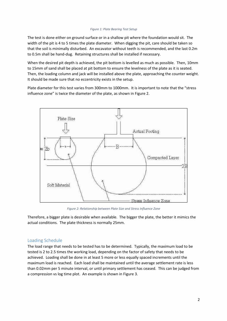
Plate diameter for this test varies from 300mm to 1000mm. It is important to note that the “stress
influence zone” is twice the diameter of the plate, as shown in Figure 2.
Figure 2: Relationship between Plate Size and Stress Influence Zone
Therefore, a bigger plate is desirable when available. The bigger the plate, the better it mimics the
actual conditions. The plate thickness is normally 25mm.
Loading Schedule The load range that needs to be tested has to be determined. Typically, the maximum load to be
tested is 2 to 2.5 times the working load, depending on the factor of safety that needs to be
achieved. Loading shall be done in at least 5 more or less equally spaced increments until the
maximum load is reached. Each load shall be maintained until the average settlement rate is less
than 0.02mm per 5 minute interval, or until primary settlement has ceased. This can be judged from
a compression vs log time plot. An example is shown in Figure 3.

3
Figure 3: Compression vs Log Time
It can be seen that primary consolidation ends when the settlement rate begins to slow down
towards the end of the cycle. A turning point exists when primary consolidation ends and secondary
consolidation begins.
Table 1 shows a sample loading step where the working load is 200 kN/m2. The maximum load to be
tested is 2.5 times the working load.
Working Load: 200 kN/m2 Max. Load: 500 kN/m2
Loading (% of working load) 0, 25, 50, 75, 100, 125, 150, 175, 200, 225, 250
Unloading (% of working load) 200, 150, 100, 50, 0 Table 1: Sample Loading Steps
In this loading schedule, the load is increased by 25% or 50 kN/m2 until it reaches the maximum load
to be tested, which is 500 kN/m2. Each load is held at constant pressure for 15 minutes. Then,
unloading is done by reducing the pressure by 50 kN/m2 every 15 minutes.
Allowable Settlement The allowable settlement has to be determined by the design engineer. Although the soil’s bearing
capacity might be satisfactory, caution has to be taken that the settlement is within allowable range.
If the soil sinks rapidly, it is deemed to have passed its ultimate bearing capacity.
The ultimate bearing capacity is sometimes considered as the load at which settlement of 25mm
occurs. The allowable bearing capacity, with a factor of safety of 2, would be one half of the
ultimate bearing capacity.
ASTM vs BS The American and British standards for the Plate Bearing Test are similar. However, there are some
differences that will be discussed here. According to ASTM, the width of a test pit being dug has to
be at least 4 times of the plate diameter. However, BS says this width has to be limited between 4 to
5 times the plate diameter.

4
ASTM also says that the plate diameter or width is between 300mm – 1000mm. BS specifies 300mm
– 600mm.
Key Points When conducting plate bearing tests, it is important to note the following:
Frequency of test – Sufficient number of tests should be conducted for each project site
Plate size – Bigger plates are desirable when available since the effective depth tested is only
twice the plate diameter
Preparation of test pit – Minimal disturbance to test pit is required for accurate results
Range of test load – A suitable factor of safety will determine the maximum load to be
tested
Allowable settlement – Although the bearing capacity might be adequate, excessive
settlement will deem failure of the soil
SAMPLE METHOD STATEMENT The method statement presented here is the one used at the site visited.
Standard used ASTM Test D1194-72 – Standard Test Method for Bearing Capacity of Soil for Static Load and Spread
Footing.
Instruments Loading Jack: 10 tonnes hydraulic (Enerpac RC106)
Pressure Gauge: 0 – 10,000 psi
Settlement Gauge: 0 – 50mm with 0.01mm least count
Plate: 300mm diameter
Test Criteria Working Load: 200 kN/m2
Maximum Load on Plate: 400 kN/m2
Preloading bearing pressure before actual testing: 20 kN/m2
Test Setup 1. The test pit and reaction load which is sufficiently more than the test loads are prepared.
2. The bottom surface of the pit shall be levelled and the plate is placed at the centre over an
evenly spread sand bed of not more than 10mm.

5
3. Loading column of sufficient length shall be placed at the centre of the plate and the jack
shall be set at the top of the loading column without any eccentricity to the reaction load.
4. Two settlement gauges with magnetic bases are positioned diagonally over the edges of the
plate. These gauges will measure settlement with reference to a datum bar supported away
from the load influence zone.
Loading Schedule The table below shows a loading schedule where the working load is 200 kN/m2 and the maximum
load is twice the working load. At maximum load, the pressure is maintained for 3 hours.
Working Load: 200 kN/m2 Max. Load: 400 kN/m2
Increment Load as % of Working Load (%)
Bearing Pressure (kN/m2)
Applied Load for 300mm dia. Plate (kN)
Jack Gauge Reading (psi)
Minimum Holding Time (Minutes)
Remarks
10 20 1.41 141 0 Preloading bearing pressure
25 50 3.53 352 15 Reading shall be recorded at 5 minute intervals for the first 15 minutes and at 15 minute intervals thereafter.
50 100 7.07 705 15
75 150 10.60 1057 15
100 200 14.14 1409 15
125 250 17.67 1762 15
150 300 21.21 2114 15
175 350 24.74 2466 15
200 400 28.27 2819 3 hours
150 300 21.21 2114 15
100 200 14.14 1409 15
50 100 7.07 705 15
0 0 0 0 15
Total 5 hrs 45 mins
Table 2: Test Loading Schedule
SITE VISIT Below are a few points I would like to discuss from the site visit. The site was located at 9th mile,
Kuching. It was a commercial shop lot project. The visit was made in the morning of 12 February
2014.
Test Pit The test pit was dug using an excavator with teeth. After excavating to the approximate depth
required, the operator was asked to lightly compact the soil with the excavator bucket. Then, the
excavator was parked above the pit as the counter weight.
One problem faced here was that the pit depth was not accurate enough. Therefore, the excavator
operator had to re-dig several times, delaying the test. In my opinion, the testing company should

6
have dug the last 0.2m-0.5m manually using a spade to achieve the desired depth. Alternatively,
suitable extensions could have been used to adjust the height of the loading column set up. Also, by
using the bucket with teeth, the soil in the pit would have loosened. This will affect the settlement
readings. Thus, digging the last few hundred millimetres manually is highly recommended so as to
minimise soil disturbance.
Plate Size A round plate with a diameter of 300mm was used in this test. Therefore, the effective depth tested
was up to 600mm beneath the test pit. This seems quite shallow. Therefore, it is important that the
test pit is being dug to the level where the footing might sit. However, when large plates exists, they
are always desirable.
Loading Schedule The loading schedule as in Table 2 was used at this site. The working load was 200 kN/m2, and the
maximum load tested was 400 kN/m2.
Test Results The test results are tabulated as follows:
Table 3: Test Results
Bearing Pressure (kN/m2)
Applied Load for 300mm dia. Plate (kN)
Jack Gauge Reading (psi)
Maximum Settlement (mm)
50 3.53 352 0.77
100 7.07 705 1.49
150 10.60 1057 4.95
200 14.14 1409 7.99
250 17.67 1762 16.99
300 21.21 2114 27.05
350 24.74 2466 29.85
400 28.27 2819 35.77
The test was stopped at the bearing pressure of 400 kN/m2 without proceeding with unloading
because the settlement had exceeded the allowable limit of 30mm, which was predetermined by the
design engineer. At 350 kN/m2, the settlement was 29.85mm and at 400 kN/m2 the settlement had
increased to 35.77mm. We can therefore deduce that the ultimate bearing capacity is
approximately 350 kN/m2 and the allowable bearing capacity (with a Factor of Safety of 2) is 175
kN/m2. The loading vs settlement graph is plotted below.

7
Figure 4: Loading vs Settlement
From the graph, it can be seen that between 100 kN/m2 to 200 kN/m2 and 300 kN/m2 to 400 kN/m2,
the settlement rate was about the same. Between 200 kN/m2 to 300 kN/m2, the settlement rate
was slightly higher. This implies that as soon as construction completes, a higher settlement rate
would be experienced if additional loads are added.
CONCULSION The Plate Bearing Test is done when shallow foundations are to be used, or when temporary work
structures would be used at a site. It checks the bearing capacity of the soil and possible settlement
at a given load. Caution has to be exercised when following test standards. Factors to be considered
by the engineer include number of tests needed at the site, load range to be tested, size of the plate,
and allowable settlement.
In some cases, although not recommended, the design engineer has to modify the standard
procedure to suit local conditions. Nonetheless, sound judgment is needed whenever deviations
from the standards are deemed necessary.
REFERENCES 1. http://www.southerntesting.co.uk/services/ground-investigation/plate-bearing-test
2. http://geo.uk.com/site-services/plate-bearing-test
3. http://environment.uwe.ac.uk/geocal/SoilMech/consol/soilcons.htm
4. Infratech ASTM Co., Ltd. (2009) Method Statement for PLATE BEARING TESTS, Bangkok, Thailand.
0
5
10
15
20
25
30
35
40
0 50 100 150 200 250 300 350 400 450
Sett
lem
ent
(mm
)
Loading (kN/m2)

8
APPENDIX
Test pit excavation
Site supervisors and testing crew inspecting work in progress

9
Pit preparation – laying of sand to ensure levelness at the bottom of the pit for test plate and loading
column to sit on
Test setup completed and is ready for loading

10
A tarpaulin is used to cover the apparatus from inclement weather