plastics and composites - michigan state university research phd/a study of flexural... ·...
TRANSCRIPT

http://jrp.sagepub.com
CompositesPlastics and Journal of Reinforced
DOI: 10.1177/073168440202101104 2002; 21; 919 Journal of Reinforced Plastics and Composites
S. C. Ng and S. Lee Strengthened with Carbon Fiber-Reinforced Plastic (CFRP)
A Study of Flexural Behavior of Reinforced Concrete Beam
http://jrp.sagepub.com/cgi/content/abstract/21/11/919 The online version of this article can be found at:
Published by:
http://www.sagepublications.com
found at:can beJournal of Reinforced Plastics and Composites Additional services and information for
http://jrp.sagepub.com/cgi/alerts Email Alerts:
http://jrp.sagepub.com/subscriptions Subscriptions:
http://www.sagepub.com/journalsReprints.navReprints:
http://www.sagepub.com/journalsPermissions.navPermissions:
© 2002 SAGE Publications. All rights reserved. Not for commercial use or unauthorized distribution. at MICHIGAN STATE UNIV LIBRARIES on October 9, 2007 http://jrp.sagepub.comDownloaded from

A Study of Flexural Behaviorof Reinforced Concrete BeamStrengthened with Carbon
Fiber-Reinforced Plastic (CFRP)
S. C. NG AND S. LEE*
Advanced Engineering Materials Facility, Hong Kong University ofScience & Technology, Clear Water Bay, N.T., Hong Kong
ABSTRACT: This paper presents an analytical study on the flexural behavior of rein-forced concrete beams strengthenedwith externally bonded carbon fiber-reinforced plastic(CFRP) laminates. Different failure modes of these strengthened reinforced beams havebeen reported and these failure modes are generally referred to as brittle failure or ductilefailure involving the compression crushing of the concrete, debonding or rupture of thecomposite laminate and yielding of the steel reinforcement. For the analysis, the stressesand strains of all the components of the beam are related by the material properties,including the stress-strain curves for the concrete, steel and CFRP laminate. The straindistribution is assumed to be compatible within the distorted shape of the cross-section ofthe concrete beam. The resultant forces on the cross section are balanced with the appliedloads for static equilibrium. The analytical solution is derived from the equilibrium equa-tions and the compatibility of the strains, and it is applicable to both singly and doubly rein-forced concrete beams strengthened with multi-layers of CFRP laminates. In this study, asimple and direct analytical procedure has been developed to evaluate the flexural capacityof concrete beams strengthened with CFRP and to predict their failure modes. An exampleis presented to illustrate the computational procedures. For design purposes, the upper andlower limits of CFRP cross-section areas are established to ensure that reinforced concretebeam strengthened with advanced composite materials will fail in a ductile manner. Acomparison between the analytical results and the data obtained from the literature hasbeen made and the agreement is very good.
KEY WORDS: carbon fiber reinforced plastic, strengthening, analysis, reinforcedconcrete.
*Author to whom correspondence should be addressed.
919Journal of REINFORCED PLASTICS AND COMPOSITES, Vol. 21, No. 10/2002
0731-6844/02/10 0919–20 $10.00/0 DOI: 10.1106/073168402025759 2002 Sage Publications
© 2002 SAGE Publications. All rights reserved. Not for commercial use or unauthorized distribution. at MICHIGAN STATE UNIV LIBRARIES on October 9, 2007 http://jrp.sagepub.comDownloaded from

INTRODUCTION
SEVERE PREMATURE DETERIORATION has been reported in a large number ofconcrete structures in corrosive and/or marine environments [1]. Many
concrete structures built in the past decades are already showing signs of deteriora-tion due to the corrosive environment. Different techniques have been developedto repair a variety of structural deficiencies. The conventional methods includesteel jacketing of concrete columns and external post-tensioning or bonding steelplates to concrete beams. However, these conventional techniques are not costeffective and some generic problems such as corrosion will also be present afterthe repair. For economical benefits, innovative repair techniques will have to bedeveloped so that durability of the concrete structure can be improved and theservice life prolonged.The development of advanced composite materials for the aerospace industry
presents new possibilities for the application of these materials in civil engi-neering. Advanced composite materials offer advantages such as low weight,excellent , a range of elastic moduli, high resistance to corrosion, high strength,availability in long lengths thus avoiding the need for lapping, and good fatigueand creep characteristics. Recent studies have shown that advanced compositematerials can strengthen structural elements such as columns and beams, leadingto great economic benefit in repairing damaged structures [2,3]. However, thechoice of the composite and the manufacturing and application procedures mustbe well defined to assure that the retrofitted structural elements will consistentlyhave the required performance. In order to characterize these materials and togenerate a database for the design procedure for this relatively new repair tech-nology, an extensive experimental program will be conducted to generate designallowable data. Theoretical analysis is a very useful and powerful tool to providenecessary guidance in the design. This study is aimed at developing analyticalcapabilities for predicting flexural behavior of reinforced concrete beamsstrengthened with advanced composite materials.
ANALYSIS OF THE CROSS-SECTION OF A BEAM
Three principles used for the analysis of the cross-section of a beam are:
1. Stresses and strains are related by the material properties of concrete, steel andCFRP.
2. Strain distribution must be compatible with the distorted shape of thecross-section.
3. Resultant forces on the cross-section must be balanced with the applied loadsfor static equilibrium.
920 S. C. NG AND S. LEE
© 2002 SAGE Publications. All rights reserved. Not for commercial use or unauthorized distribution. at MICHIGAN STATE UNIV LIBRARIES on October 9, 2007 http://jrp.sagepub.comDownloaded from

These principles are valid irrespective of how the stresses and strains are distrib-uted, how the member is loaded, and how the shape of the cross-section is elasti-cally changed.
Stress-Strain Relations
Typical stress-strain curves for concrete and steel used in this study are obtainedfrom BS 8110 and the characteristics of each curve are described as follows:
CONCRETETypical compressive behavior of structural concrete is represented by a
stress-strain relationship, see Figure 1. At a certain strain level, εo, the strainincreases while the stress remains constant. Strain is specified as a function of thestrength of the concrete, and fcu is the tangent modulus measured at the origin. Theultimate strength is given by the following expression:
(1)
where a factor of 0.67 is normally used for compensating for the differencebetween the flexural strength and the cube crushing strength of the concrete, andγ c = 1.5 is a safety factor for the strength of the concrete when the designedmember is cast in situ, or γ c = 1.0 when the member is cast in the laboratory fortesting. The ultimate strain of εcu = 0.0035 is a typical value for all grades ofconcrete.
Flexural Behavior of Reinforced Concrete Beam Strengthened with CFRP 921
0.45 for 1.5 (design)0.67
0.67 for 1.0 (testing)
cu ccu
c cu c
ff
f
== =
γ
γ γ
Figure 1. A typical stress-strain curve for concrete in compression.
© 2002 SAGE Publications. All rights reserved. Not for commercial use or unauthorized distribution. at MICHIGAN STATE UNIV LIBRARIES on October 9, 2007 http://jrp.sagepub.comDownloaded from

STEEL REINFORCEMENTA typical stress-strain curve for steel reinforcement is presented in Figure 2. The
behavior of the steel is assumed to be identical in tension and compression, beinglinear in the elastic range up to the yield stress of fy/γ s, where fy is the characteristicyield stress, and γ s = 1.15 is a factor of safety for design purpose or γ s = 1.0 fortesting.The relationship between the stress and strain is presented in the following
expression:
(2)
and the yield strain is
(3)
At the ultimate strength, the design (γ s = 1.15) yield strain is εy = 0.2% for highyield steel fy = 460 N/mm
2, and it is εy = 0.1087% for mild steel fy = 250 N/mm2.The testing (γ s=1.0) yield strain is εy=0.23% for high yield steel and εy=0.125%for mild steel.
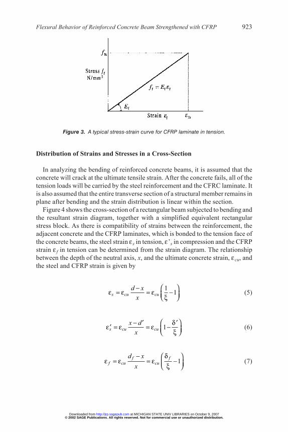
CFRP LAMINATEA typical stress-strain curve for CFRP laminates in tension is given in Figure 3.
The relationship between the stress and strain is linear and the elastic range isgiven in the following expression
(4)
922 S. C. NG AND S. LEE
/y sy
s
f
E=
γε
Figure 2. A typical stress-strain curve for mild steel reinforcement in tension and in com-pression.
/y sy
s
f
E=
γε
f f ff E= ε
© 2002 SAGE Publications. All rights reserved. Not for commercial use or unauthorized distribution. at MICHIGAN STATE UNIV LIBRARIES on October 9, 2007 http://jrp.sagepub.comDownloaded from
Distribution of Strains and Stresses in a Cross-Section
In analyzing the bending of reinforced concrete beams, it is assumed that theconcrete will crack at the ultimate tensile strain. After the concrete fails, all of thetension loads will be carried by the steel reinforcement and the CFRC laminate. Itis also assumed that the entire transverse section of a structural member remains inplane after bending and the strain distribution is linear within the section.Figure 4 shows the cross-section of a rectangular beam subjected to bending and
the resultant strain diagram, together with a simplified equivalent rectangularstress block. As there is compatibility of strains between the reinforcement, theadjacent concrete and the CFRP laminates, which is bonded to the tension face ofthe concrete beams, the steel strain ε s in tension, ε’s in compression and the CFRPstrain ε f in tension can be determined from the strain diagram. The relationshipbetween the depth of the neutral axis, x, and the ultimate concrete strain, εcu, andthe steel and CFRP strain is given by
(5)
(6)
(7)
Flexural Behavior of Reinforced Concrete Beam Strengthened with CFRP 923
11s cu cu
d x
x
−= = −
ε ε εξ
1s cu cux d
x
− ′ ′= = −′ δ
ε ε εξ
1f f
f cu cu
d x
x
− = = −
δε ε ε
ξ
Figure 3. A typical stress-strain curve for CFRP laminate in tension.
© 2002 SAGE Publications. All rights reserved. Not for commercial use or unauthorized distribution. at MICHIGAN STATE UNIV LIBRARIES on October 9, 2007 http://jrp.sagepub.comDownloaded from

in which depth factors of the beam section
(8)
where d is the effective depth of the tensile steel reinforcement, d′ the depth of thecompression reinforcement and df is the depth of the CFRP laminates.Having determined the strains, the stresses in the steel reinforcement and CFRP
laminates can be obtained from the stress-strain curves of Figures 2 and 3, togetherwith the equations developed in section 2.1.
Equilibrium Equation and Ultimate Moment of Resistance
Bending will induce forces acting on the section. These forces are shown inFigure 4(c) and are derived in the following expressions:
Concrete compression = (0.67fcu /γ c)b(0.9x) = 0.6(fcu /γ c)bx, acting at thecentroid of the effective area of the concrete
Reinforcement compression =Reinforcement tension = fsAs
CFRP tension = ffAf
From the equilibrium condition, the equilibrium equation is obtained as:
(9)
924 S. C. NG AND S. LEE
s sf A′ ′
, ,f
f
dx d
d d d
′= = =′ξ δ δ
(a) Cross-section (b) Strains (c) Stresses and forces
Figure 4. Cross-section with strain diagram and stress block.
0.6 cus s s s f f
c
fbx f A f A f A+ = +′ ′
γ
© 2002 SAGE Publications. All rights reserved. Not for commercial use or unauthorized distribution. at MICHIGAN STATE UNIV LIBRARIES on October 9, 2007 http://jrp.sagepub.comDownloaded from

That is
(10)
where the area ratios of tension steel, compression steel and tension CFRP are
(11)
The ultimate flexural strength, M (often called the ultimate moment of resis-tance), of the beam is then obtained by taking moments about a convenient hori-zontal axis. For example, taking moments about the centroid of the concrete stressblock (Figure 4) gives
(12)
or, taking moments about the level of the compression bar yields
(13)
or, taking moments about the level of the tension bar yields
(14)
or, taking moments about the level of the laminate plate yields
(15)
The M values from these equations are essentially equal in magnitude.
BALANCED SECTION
Flexural Failure Modes
Reinforced concrete beams strengthened with externally bonded CFRP rein-forcement could fail in any of the following flexural failure modes (Figure 5):
Flexural Behavior of Reinforced Concrete Beam Strengthened with CFRP 925
20.6 ( 0.45 ) ( 1) ( )cu
f s f f f fc
M ff f
bd= − + − + −′ ′ ′ξ δ ξ ρ δ ρ δ δ
γ
20.6 (1 0.45 ) (1 ) ( 1)cu
s f f fc
M ff f
bd= − + − + −′ ′ ′ξ ξ ρ δ ρ δ
γ
2(1 0.45 ) ( 0.45 ) ( 0.45 )s f f f s
Mf f f
bd= − + − − −′ ′ ′ρ ξ ρ δ ξ ρ δ ξ
20.6 ( 0.45 ) (1 ) ( )cu
f f fc
M ff f
bd= − + − + −′ ′ ′ξ δ ξ ρ δ ρ δ δ
γ
0.6 cus s f f
c
ff f f+ = +′ ′ξ ρ ρ ρ
γ
, ,fs s
f
AA A
bd bd bd
′= = =′ρ ρ ρ
© 2002 SAGE Publications. All rights reserved. Not for commercial use or unauthorized distribution. at MICHIGAN STATE UNIV LIBRARIES on October 9, 2007 http://jrp.sagepub.comDownloaded from

1. Compression failure, in which the concrete crushes in compression before thereinforcing steel yields;
2. Tension failure, in which concrete crushing follows the yielding of the rein-forcing steel in tension;
3. CFRP rupture, in which the rupture of CFRP laminate follows the yielding ofreinforcing steel in tension.
These three failure modes can be schematically illustrated in Figure 5.When the areas of reinforcing bar As and CFRP Af are above certain values
(above the line ab in Figure 5), compression failure of a beam with heavy rein-forcement will occur with the crushing of the concrete, while the steel and CFRPstrains are still relatively low. This type of failure is characterized by a smalldeflection of the beam and by the absence of extensive cracking in the tensionzone. The failure, often non-ductile and explosive, occurswithout earlywarning.Tension failure of a beamwith light reinforcement is characterized by large steel
and CFRP strains, and the beamwill exhibit extensive cracking in the concrete anda substantial deflection. This type of failure process is considered to be ductile andit provides ample warning of an impending failure. For practical and economicalconsideration, designers should aim at designing a beamwith aminimal reinforce-mentwhile providing themaximum flexural capability, which is the bacd region inFigure 5.When the areas of reinforcing bar As and CFRP Af are below certain values
(below line cd in Figure 5), CFRP rupturewill occur before the concrete attains theultimate compressive strain. This type of failure is a less-ductile failure.
926 S. C. NG AND S. LEE
Figure 5. Schematic illustrating failure modes and balanced sections for CFRP strength-ened beam.
© 2002 SAGE Publications. All rights reserved. Not for commercial use or unauthorized distribution. at MICHIGAN STATE UNIV LIBRARIES on October 9, 2007 http://jrp.sagepub.comDownloaded from

From a practical point of view, it is necessary that upper and lower limits of bothreinforcing bar and CFRP areas can be established so that a proper amount of rein-forcement can be chosenwithin the range and that the failure of the beamwill be ina ductile fashion. For this purpose, analysis of a balanced section for achieving theductile behavior is presented in the following section:
Balanced Section 1
Section 1 is said to be balanced if the concrete strain εc reaches the ultimatestrain, εcu, simultaneously with the bottom tension steel strain, ε s reaching yieldstrain, εy. Meanwhile, the compression steel strain and the CFRPstrain.That is, the strain distribution at collapse is as shown in Figure 6. The depthfactor of the neutral axis (ξ = x/d has a value and is given in Equation (5) with ε sand can be replaced by εy:
(16)
and from Equation (7),
(17)
In this case, the equation of the force equilibrium, given by Equation (10) with fsreplaced by fy/γ s and becomes
Flexural Behavior of Reinforced Concrete Beam Strengthened with CFRP 927
1
1f
f cu
= − δ
ε εξ
s y>′ ′ε ε
18
cu
cu y
=+
εξ
ε ε
Figure 6. Strain distribution in balanced section 1.
by / ,s y sf f′ ′ γ
© 2002 SAGE Publications. All rights reserved. Not for commercial use or unauthorized distribution. at MICHIGAN STATE UNIV LIBRARIES on October 9, 2007 http://jrp.sagepub.comDownloaded from
(18)
A maximum CFRP cross-sectional area Af,max should be provided to prevent acompression failure as follows:
(19)
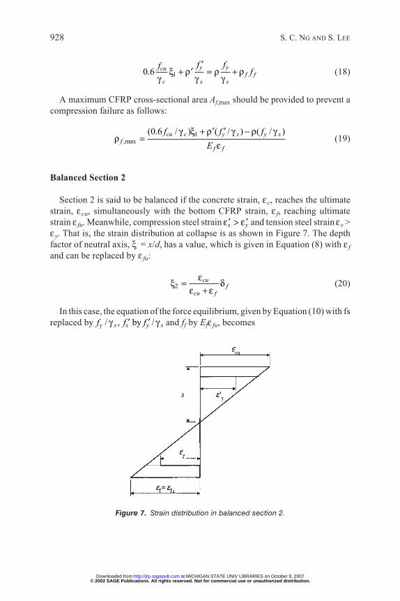
Balanced Section 2
Section 2 is said to be balanced if the concrete strain, εc, reaches the ultimatestrain, εcu, simultaneously with the bottom CFRP strain, ε f, reaching ultimatestrain ε fu. Meanwhile, compression steel strain and tension steel strain s >εy. That is, the strain distribution at collapse is as shown in Figure 7. The depthfactor of neutral axis, ξ = x/d, has a value, which is given in Equation (8) with ε fand can be replaced by ε fu:
(20)
In this case, the equation of the force equilibrium, given byEquation (10)with fsreplaced by and ff by Efε fu, becomes
928 S. C. NG AND S. LEE
2cu
fcu f
=+
εξ δ
ε ε
s y>′ ′ε ε
10.6y ycu
f fc s s
f fff
′+ = +′ξ ρ ρ ρ
γ γ γ
1,max
(0.6 / ) ( / ) ( / )cu c y s y sf
f f
f f f
E
+ −′ ′=
γ ξ ρ γ ρ γρ
ε
Figure 7. Strain distribution in balanced section 2.
/ , by /y s s y sf f f′ ′γ γ
© 2002 SAGE Publications. All rights reserved. Not for commercial use or unauthorized distribution. at MICHIGAN STATE UNIV LIBRARIES on October 9, 2007 http://jrp.sagepub.comDownloaded from

(21)
A minimum CFRP cross-sectional area Af,min should be provided to avoid afailure, in which the CFRP rupture occurs before the concrete attains the ultimatecompressive strain, thus inducing a less-ductile failure,where k=0.6 as follows:
(22)
COMPUTATION FORMULAE
In practical cases, the depth factors of the neutral axis (ξ )are given by Equa-tions (16) and (20), and ξ , iswithin the range of the balanced sections 1 and 2, i.e.,
(23)
The equation of the force equilibrium, given by Equation (10) with fs replacedby fy/γ s and ff by Ef ε f, then becomes
(24)
Dividing both sides of Equation (24) by (0.6fcu/γ c) yields
(25)
The equation of moment resistance, given by Equation (15) with fs replaced byfy/γ s and then becomes
(26)
Dividing both sides of Equation (26) by (0.6fcu/γ c) yields
(27)
Flexural Behavior of Reinforced Concrete Beam Strengthened with CFRP 929
by / ,s y sf f′ ′ γ
20.6 ( 0.45 ) ( 1) ( )
y ycuf f f
c s s
f fM f
bd
′= − − − + −′ ′ξ δ ξ ρ δ ρ δ δ
γ γ γ
/ /1
0.6 / 0.6 / 0.6 /y s y s f cu f
fcu c cu c cu c
f f E
f f f
∂′ + = + ⋅ −′
γ γ εξ ρ ρ γ
γ γ γ ξ
0.6 1y y fcu
f f cuc s s
f ffE
′ + = + −′
δξ ρ ρ ρ ε
γ γ γ ξ
2 1cu cu
fcu fu cu y
= ≤ ≤ = + +
ε εξ δ ξ ξ
ε ε ε ε
by /s y sf f′ ′ γ
2,min
( / ) ( / ) ( / )cu c y s y sf
f cu
kf f f
E
+ −′ ′=
γ ξ ρ γ ρ γρ
ε
20.6y ycu
f f fuc s s
f ffE
′+ = +′ξ ρ ρ ρ ε
γ γ γ
2/ / /( 0.45 ) ( 1) ( )
0.6 / 0.6 / 0.6 /y s y s
f f fcu c cu c cu c
f f M bd
f f f
′− − ⋅ − + ⋅ =′ ′
γ γξ δ ξ ρ δ ρ δ δ
γ γ γ
© 2002 SAGE Publications. All rights reserved. Not for commercial use or unauthorized distribution. at MICHIGAN STATE UNIV LIBRARIES on October 9, 2007 http://jrp.sagepub.comDownloaded from

Introducing the non-dimensional indices of reinforcing steels and strengtheningCFRP
(28)
and normalised moment capacity
(29)
Equations (25) and (27) become (30) and (31), respectively,
(30)
(31)
This pair of equations is the basic set of equations for analysing the flexuralbehavior of reinforced concrete beams strengthenedwith externally bondedCFRPlaminates. Hence, a simple and direct computation procedure for design has beendeveloped for determining the CFRP cross-sectional area, or evaluating the ulti-mate flexural capacity to ensure ductile behavior of the tension failure of rein-forced concrete beams strengthened with CFRP laminate
COMPUTATION PROCEDURE
Consider the beam section in Figure 4(a). The computation procedure is givenas follows.
Determination of CFRP Area
Suppose the bending moment isM and the area of the tension reinforcing bar isAs and the area of the compression reinforcing bar is
Step 1. Calculate the indices of the reinforcing steel and normalised momentcapacity from Equations (11), (28) and (29):
930 S. C. NG AND S. LEE
( 0.45 ) ( 1) ( )f f f m− − − + − =′ ′ξ δ ξ δ φ δ δ φ
2/
0.6 /cu c
M bdm
f=
γ
1f
f
+ = + −′ δ
ξ φ φ φξ
/ /, ,
0.6 / 0.6 / 0.6 /y s y s f cu
f fcu c cu c cu c
f f E
f f f
′= = =′ ′
γ γ εφ ρ φ ρ φ ρ
γ γ γ
.sA′
2/ / /, , and
0.6 / 0.6 / 0.6 /y s y s
cu c cu c cu c
f f M bdm
f f f
′= = =′ ′
γ γφ ρ φ ρ
γ γ γ
© 2002 SAGE Publications. All rights reserved. Not for commercial use or unauthorized distribution. at MICHIGAN STATE UNIV LIBRARIES on October 9, 2007 http://jrp.sagepub.comDownloaded from

Step 2. Calculate the depth factors of the neutral axis of the balanced sectionsfrom Equations (16) and (20)
Step 3. Determine the depth factor of the neutral axis from Equation (31)
Step 4. If ξ 2 ≤ξ ≤ξ 1, then determine the area of the CFRP fromEquations (30)and (11)
Evaluation of Ultimate Flexural Capacity
Suppose the area of the tension reinforcing bar isAs, the area of the compressionreinforcing bar is and the area of the CFRP is Af.
Step 1. Calculate the indices of the reinforcing steel and the strengtheningCFRPfrom Equation (28).
Step 2. Calculate the depth factors of the neutral axis of the balanced sectionsfrom Equations (16) and (20)
Step 3. Determine the depth factor of the neutral axis from Equation (30)
Flexural Behavior of Reinforced Concrete Beam Strengthened with CFRP 931
1 2andcu cuf
cu y cu fu
= =+ +
ε εξ ξ δ
ε ε ε ε
/ /, ,
0.6 / 0.6 / 0.6 /y s y s f cu
fcu c cu c cu c
f f E
f f f
′= = =′ ′
γ γ εφ ρ φ ρ φ
γ γ γ
sA′
0.6 /and
/ 1cu c
f f f ff f cu
fA bd
E
− + ′= = =−
ξ φ φ γφ ρ φ
δ ξ ε
2( 1) ( )
0.9 0.9 0.45f f f fm + − − − ′ ′
= − − δ δ δ φ δ δ φ
ξ
1 2andcu cuf
cu y cu fu
= =+ +
ε εξ ξ δ
ε ε ε ε
2
2 2f f
f f
− + − +′ ′ = + −
φ φ φ φ φ φξ δ φ
© 2002 SAGE Publications. All rights reserved. Not for commercial use or unauthorized distribution. at MICHIGAN STATE UNIV LIBRARIES on October 9, 2007 http://jrp.sagepub.comDownloaded from

Step 4. If ξ 2 ≤ ξ ≤ ξ 1, then evaluate the ultimate flexural capacity from Equa-tions (31) and (29)
AN EXAMPLE FOR ILLUSTRATION OF THE PROCEDURES
Beam Configuration
A beam section is shown in Figure 8. The material properties are: fcu = 30N/mm2 for the concrete, =250N/mm2 for the compressive steel, fy= 460N/mm
2
for the tensile steel and ffu = 4,200N/mm2 for the CFRP laminates. Themodulus of
elasticity is Es = 200 GPa for the steel and Ef = 235 GPa for the CFRP laminates.The design/test moment at the ultimate and limit state causes sagging of the beam.The partial safety factors are γ c = 1.5 and γ s = 1.15 for the design and γ c = γ s = 1.0for the test.
The section data
The data are as follows:b = 150 mm, d = 190 mm, d′ = 30 mm, df = 220 mm,
then from Equation (8)
δ′ = 0.157, δf = 1.157
932 S. C. NG AND S. LEE
yf ′
2( 0.45 ) 1) ( ) and (0.6 / )f f f cu cm M m bd f= − − − + − = ⋅′ ′ξ δ ξ δ φ δ δ φ γ
Section Strains
Figure 8. CFRP-strengthened reinforced concrete beam.
© 2002 SAGE Publications. All rights reserved. Not for commercial use or unauthorized distribution. at MICHIGAN STATE UNIV LIBRARIES on October 9, 2007 http://jrp.sagepub.comDownloaded from

and the depth factors of balanced sections from Equations (16) and (20)
ξ 1 = 0.636 and ξ 2 = 0.178.
Provide two R8 bars for compression reinforcing:
Provide two T12 or T16 bars for tension reinforcing:
ProvideRenoCarbonFiber Sheet (MRL-T7-300) of 1-5 ply for strengthening:
Results and Comparison
The computation procedures were presented in Section 5.2. Results andcomparison are shown in Table 1 and Figure 9.It is noted that most design and test failures are from ductile tension because of
the fact that
except when the compression failure for the design beam using 2-T16 reinforcingand 5-ply CFRP strengthening because of the fact that
Close scrutiny of Table 1 andFigure 9 reveals several interesting observations:
1. The external bonding of the CFRP laminates can significantly increase the ulti-mate flexural capacity, M, of the reinforced concrete beams.
Flexural Behavior of Reinforced Concrete Beam Strengthened with CFRP 933
2 1( 0.178) ( 0.636)= < < =ξ ξ ξ
As = ρ′ bd(mm2)
100ρ′ d
φ′ forDesign
φ′ forTest
As = ρbd(mm2)
100 ρ φ for Design φ for Test
2-T12 226 0.794 0.2646 0.2028
Af = ρ fbd (mm2) 100 ρ f φf for Design ωf for Test
1 Ply 25 0.088 0.060 0.0402 Ply 50 0.175 0.120 0.0803 Ply 75 0.263 0.180 0.1204 Ply 100 0.351 0.241 0.1605 Ply 125 0.439 0.301 0.200
( 0.643) ( 0.636)1= > =ξ ξ
© 2002 SAGE Publications. All rights reserved. Not for commercial use or unauthorized distribution. at MICHIGAN STATE UNIV LIBRARIES on October 9, 2007 http://jrp.sagepub.comDownloaded from

934 S. C. NG AND S. LEE
Table 1. Results and comparison.
No. ofPlies
TensionBar
2-T12 2-T16
Design Test Design Test
0 ξM
M (kN-m)
0.20070.236915.4
0.15380.184818.0
0.40640.386425.1
0.31160.309530.2
1 ξM
M (kN-m)
0.34240.365323.7
54.2%
0.27900.304429.7
64.7%
0.48800.447429.1
15.8%
0.38980.374836.5
21.1%
2 ξM
M (kN-m)
0.41420.423427.5
78.8%
0.34270.359835.1
94.7%
0.54150.484231.5
25.3%
0.44060.414340.4
33.8%
3 ξM
M (kN-m)
0.46570.462230.0
95.1%
0.38900.397938.8
115.3%
0.58230.51033.2
32.1%
0.47970.443043.2
43.1%
4 ξM
M (kN-m)
0.50640.491231.9
107.4%
0.42620.426941.6
131.0%
0.61540.530634.5
37.3%
0.51160.465545.4
50.4%
5 ξM
M (kN-m)
0.54010.514233.4
117.0%
0.45740.450443.9
143.7%
0.64330.546935.5
41.5%
0.53890.483947.2
56.3%
© 2002 SAGE Publications. All rights reserved. Not for commercial use or unauthorized distribution. at MICHIGAN STATE UNIV LIBRARIES on October 9, 2007 http://jrp.sagepub.comDownloaded from

2. This effect is more pronounced for beams having relatively small steel rein-forcement area, As.
3. For any particular reinforced concrete beam, the rate of increase in the ultimateflexural capacity decreaseswhile theCFRP cross-sectional area,Af, increases.
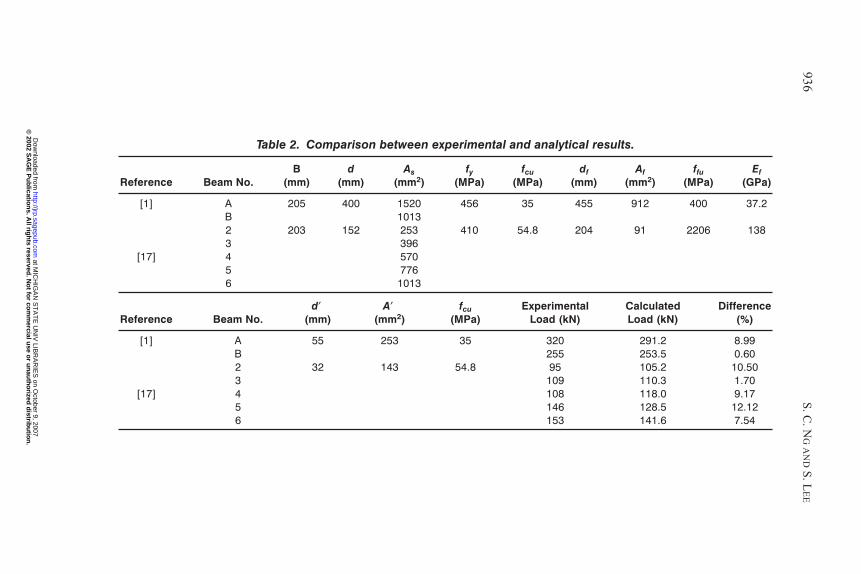
SECTION ANALYSIS VERIFICATION
To verify the results of the computation procedure for section analysis, acomparison is made between the ultimate load capacity obtained experimentallyby different researchers and the predicted ultimate flexural strength using theanalytical method described in this paper. The results of the comparison aresummarised in Table 2. All beams were tested with four-point bending over a
Flexural Behavior of Reinforced Concrete Beam Strengthened with CFRP 935
Figure 9. Results and comparison.
© 2002 SAGE Publications. All rights reserved. Not for commercial use or unauthorized distribution. at MICHIGAN STATE UNIV LIBRARIES on October 9, 2007 http://jrp.sagepub.comDownloaded from
936S.C.N
GANDS.LEE
Table 2. Comparison between experimental and analytical results.
Reference Beam No.B
(mm)d
(mm)As
(mm2)fy
(MPa)fcu
(MPa)df
(mm)Af
(mm2)ffu
(MPa)Ef
(GPa)
[1] A 205 400 1520 456 35 455 912 400 37.2B 10132 203 152 253 410 54.8 204 91 2206 1383 396
[17] 4 5705 7766 1013
Reference Beam No.d
(mm)A
(mm2)fcu
(MPa)Experimental
Load (kN)CalculatedLoad (kN)
Difference(%)
[1] A 55 253 35 320 291.2 8.99B 255 253.5 0.602 32 143 54.8 95 105.2 10.503 109 110.3 1.70
[17] 4 108 118.0 9.175 146 128.5 12.126 153 141.6 7.54
©
2002 SA
GE
Pu
blicatio
ns. A
ll righ
ts reserved. N
ot fo
r com
mercial u
se or u
nau
tho
rized d
istribu
tion
. at M
ICH
IGA
N S
TA
TE
UN
IV LIB
RA
RIE
S on O
ctober 9, 2007 http://jrp.sagepub.com
Dow
nloaded from

certain span length. The ultimate load represents the sum of two equally concen-trated loads applied to the beam at failure. These results indicate that the analyticalmethod developed in this study is quite accurate in predicting the ultimate flexuralcapacity of reinforced concrete beams strengthened with externally bonded CFRPlaminates. The difference between the ultimate load capacity obtained experimen-tally and the predicted ultimate flexural strength using the analytical method wasaround 12%. The difference is quite small when considering all the variationsassociated with the behavior of reinforced concrete structures.
CONCLUSIONS
Theoretical analysis on the flexural behavior of a concrete beam strengthenedwith carbon fiber reinforced plastic has been carried out. The analysis is based onthe assumption that (a) strain distribution is linear at failure, (b) there is a perfectbond between the CFRP laminates and the concrete. Based on this study, severalfindings are presented as follows:
• Amaximal and aminimal value of CFRP section area have been determined andany valuewithin the range for strengtheningwould enable the beam to fail undertension which is preferable.
• Several non-dimensional parameters have been developed and used for facili-tating the analysis and calculations. These parameters are found to be veryeffective and useful in solving the relatively complex mathematical models.
• As a result of this investigation, a simple and direct computational procedurehas been developed for predicting the ultimate flexural capacity of a concretebeam strengthened with carbon fiber reinforced plastic (CFRP).
• A comparison has been made between the analytical results and the experi-mental results reported in the literature. Generally, the agreement is very goodexcept one result exhibits a discrepancy of 12%.
ACKNOWLEDGEMENT
The research presented in this paper is funded by the Hong Kong UniversityGrant Council, under a Cooperative Research Centre program (CRC98/01.EG14)and the industrial sponsor is the ASMTCo. of Lit Cheong Power Engineering Ltd.The authors would like to thank the CRC research team members and the AEMFtechnical staff for their support.
REFERENCES
1. Saadatmanesh, H. and Ehsani, M. R. (1991). “RC beams strengthened with GFRP plates. I:Experimental study.” J. of Struct. Engrg., ASCE, 117(11), 3417–3433.
Flexural Behavior of Reinforced Concrete Beam Strengthened with CFRP 937
© 2002 SAGE Publications. All rights reserved. Not for commercial use or unauthorized distribution. at MICHIGAN STATE UNIV LIBRARIES on October 9, 2007 http://jrp.sagepub.comDownloaded from

2. An, W., Saadatmanesh, H. and Ehsani, M. R. (1991). “RC beams strengthened with FRP plates.II: Analysis and parametric study.” Journal of Structural Engineering, ASCE, 117(11),3434–3455.
3. Meier, U. and Kaiser, H. (1991). “Strengthening structures with CFRP laminates.” Proc.,Advanced Compos. Mat. in Civ. Engrg. Struct., ASCE, New York, 224–232.
4. Sharif, A., A1-Sulaimani, G. J., Basunbul, I. A., Baluch, M. H. and Ghaleb, B. N. (1994).“Strengthening of initially loaded reinforced concrete beams using FRP plates.” ACI Struct. J.,91(2), 160–168.
5. Sierakowski, R. L., Ross, C. A., Tedesco, J. W. and Hughes, M. L. (1994). “Concrete beams withexternally bonded carbon fiber reinforced plastic strips.” Proceedings of the Third MaterialsEngineering Conference: Infrastructure: New materials and Methods for Repair, ASCE, SanDiego, California, 212–220.
6. Chajes, M. J., Januszka, T. F., Merz, D. R., Thomson, T. A. and Finch, W. W. (1995). “ShearStrengthening of reinforced concrete beams using externally applied composite fabrics.” ACIStruct. J., 92(3), 295–303.
7. Quantrill, R. J., Holloway, L. C. and Thorne, A. M. (1996). “Predictions of the maximum plateend stresses of FRP strengthened beams: part II.” Mag. Concrete Res., 48(177), 343–351.
8. Norris, T., Saadatmanesh, H. and Ehsani,M. R. (1997). “Shear and flexural strengthening of rein-forced concrete beams with carbon fiber sheets.” J. of Struct. Engrg., ASCE, 123(7), 903–911.
9. Arduini, M. and Nanni, A. (1997). “parametric study of beams with externally bonded FRP rein-forcement.” ACI Struct. J., 94(5), 493–501.
10. Malek, A. M. (1997). “Analytical study of reinforced concrete beams strengthened with FRPplates or fabrics,” PhD dissertation, University of Arizona, Tucson.
11. Malek, A. M., Saadatmanesh, H. and Ehsani, M. R. (1998). “Prediction of failure load of R/Cbeams strengthened with FRP plate due to stress concentration at the plate end.” ACI Struct. J.,95(1), 142–152.
12. Triantafllou, T. C. (1998). “Shear Strengthening of reinforced concrete beams usingepoxy-bonded FRP composites.” ACI Struct. J., 95(2), 107–115.
13. Malek, A. M. and Saadatmanesh, H. (1998). “Analytical study of reinforced concrete beamsstrengthened with web-bonded fiber reinforced plastic plates or fabrics.” ACI Struct. J., 95(3),343–352.
14. Malek, A. M. and Saadatmanesh, H. (1998). “On the analysis and design of reinforced concretebeams strengthened with FRP laminates.” Arabian Journal for Science and Engineering, 23(2C),167–182.
15. Saadatmanesh, H. andMalek, A.M. (1998). “Design guidelines for flexural strengthening of RCbeams with FRP plates.” J. of Compos. for Constr., ASCE, 2(4), 158–164.
16. Grace, N. F., Soliman, A. K., Sayed, G. A. and Saleh, K. R. (1998). “Behavior and ductility ofsimple and continuous FRP reinforced beams.” J. of Compos. for Constr., ASCE, 2(4), 186–194.
17. Ross, C. A., Jerome, D. M., Tedesco, J. W. and Hughes, M. L. (1999). “Strengthening of rein-forced concrete beams with externally bonded composite laminates.” ACI Struct. J., 96(2),212–220.
18. Grace, N. F., Sayed, G. A., Soliman, A. K. and Saleh, K. R. (1999). “Strengthening reinforcedconcrete beams using fiber reinforced polymer (FRP) laminates.”ACI Struct. J., 96(5), 865–874.
19. Rabinovich, O. and Frostig, Y. (2000). “Closed-form high-order analysis of RC beams strength-ened with FRP strips.” J. of Compos. for Constr., ASCE, 4(2), 65–74.
20. El-Mihilmy, M. T. and Tedesco, J. W. (2000). “Analysis of reinforced concrete beams strength-ened with FRP laminates.” J. of Struct. Engrg., ASCE, 126(6), 684–691.
938 S. C. NG AND S. LEE
© 2002 SAGE Publications. All rights reserved. Not for commercial use or unauthorized distribution. at MICHIGAN STATE UNIV LIBRARIES on October 9, 2007 http://jrp.sagepub.comDownloaded from