plastic pipe penetration sleeve brochure
DESCRIPTION
Sleeve Steel PipeTRANSCRIPT
Nailer End (ap
Page I
~)III
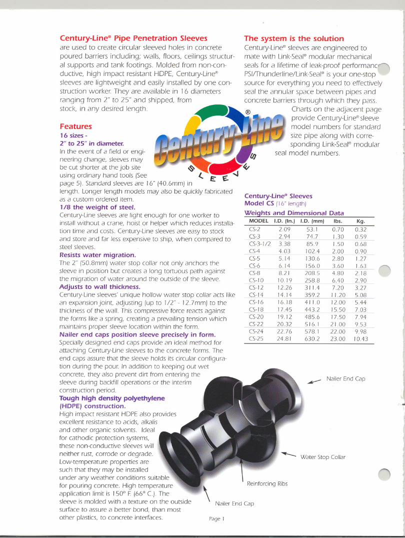
The system is the solutionCentury-Line@sleeves are engineered tomate with Link-Seal@modular mechanical
seals for a lifetime of leak-proof performancnPSlffhunderline/Link-Sea/@isyour one-stopsource for everything you need to effectivelyseal the annular space between pipes andconcrete barriers through which they pass.
Charts on the adjacent pageprovide Century-Line@sleevemodel numbers for standard
size pipe along with corre-sponding Link-Seal@modular
seal model numbers.
Century-line'" SleevesModel CS (16"length)Weights and Dimensional Data
MODEL I.D. (In.) J.D. (mm) Ibs.(5-2 2.09 53.1 0.70(5-3 294 74.7 1.30(5-3-1/2 338 85.9 1.50(5-4 403 102.4 2.00(5-5 5.14 130.6 2.80(5-6 6.14 156.0 3.60(5-8 82] 208.5 4.80(5-10 10.19 258.8 6.40(5-12 12.26 311.4 7.20(5-14 14.14 359.2 11.20(5-16 16.18 411.0 12.00(5-18 17.45 443.2 15.50(5-20 19.12 4856 17.50(5-22 20.32 516.1 21.00(5-24 22.76 578.1 22.00(5-25 248] 630.2 23.00
r,
t.,I
rI
1.J
I
II
\
Kg.0.320.59
0.680.901.271.632.182.903.275.085.447.037.949.539.98] 0.43
nI
i
~ Nailer End (ap
Reinforcing Ribs
I
J
i.rj5 -
I,
n t
I
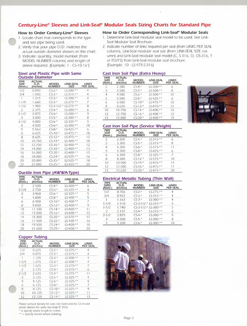
Century-line@ Sleeves and link-Seal@ Modular Seals Sizing Charts for Standard Pipe
()
MODEL LINK-SEALNUMBER SIZE
C5-2-* LS-200-**C5-3-* LS-315-**C5-3-* LS-300-**C5-3-* LS-275-**C5-3-1/2-* LS-275-**C5-4-* LS-300-**C5-4-* LS-200-* *C5-5-* LS-300-**C5-6-* LS-325-**C5-6-* LS-300-**C5-8-* LS-425-**C5- 10-* LS-475-**
C5-12-* LS-475-**!C5-14-* LS-400-**C5-16-* LS-400-**C5-18-* LS-400-**C5-20-* LS-400-* *C5-24-* LS-525-* *C5-25-* LS-525-**C5-25-* LS-425-**
LINKSPER SEAL
44478698510610121012
- 1315161820
How to Order Corresponding link-Seal@ Modular Seals1. Determine Link-Seal modular seal model to be used. See Link-
Seal Modular Seal Brochure.
2. Indicate number of links required per seal (from LINKSPER SEALcolumn), Link-Sealmodular seal size (from LINK-SEALSIZEcol-umn) and Link-Seal modular seal model (C, S-316, 0, OS-316, Tor FD/FS) from Link-Seal modular seal brochure.[Example: 10- LS-475-S-316]
Electrical Metallic Tubing (Thin Wall)PIPE ACTUAL-SIZE) O.D.fNom.) (Inches)1/2 0.706
3/4 0 922
I 1.163
1-1/4 1.510
1-1/2 1.740
2 2.197
2-1/2 2.875
3 3.500
4 4.500
How to Order Century-line@ Sleeves
0 1. Locate chart that corresponds to the typeand size pipe being used.
2. Veritythat your pipe 0.0. matches theactual outside diameter shown on the chart.
3. Indicate: quantity, model number (fromMODELNUMBERcolumn) and length ofsleeve required. [Example: I - CS-]0-] 6"]
Steel and Plastic Pipe with SameOutside DiameterPIPE ACTUALSIZE O.D.fNom.) (Inches)1/2 0.8403/4 1.050I 1315
1-1/4 1.660
1-1/2 1.900
2 2.3752-1/2 2.8753 3.500
3-1/2 4.0004 4.5005 5.5636 662-58 8.62510 10.75012 12.75014 14.00016 16.00018 18.00020 20.00022 22.000
MODEL LINK-SEALNUMBER SIZE
C5-2-* LS-27 5-* *
C5-3-* LS-315-* *
C5-3-* LS-300-**
C5-3-1/2-* LS-315-**
C5-3- I/2-* LS-300-**
C5-4-* LS-315-**
C5-4-* LS-200-**
C5-5-* LS-300-**
C5-6-* LS-300-**
LINKSPER SEAL
4445569810
Page 2
Cast Iron Soil Pipe (Extra Heavy)PIPE ACTUALSIZE O.D. MODEL LINK-SEAL LINKS
INom.) finches) NUMBER SIZE PER SEAL
2 2.380 C5-4-* LS-300-** 63 3.500 C5-5-* LS-300-** 84 4.500 C5-6-* LS-300-** 105 5.500 C5-8-* LS-425-** 66 6.500 C5-10-* LS-475-** 108 8.620 C5-12-* LS-475-** 12
10 10.750 C5-14-* LS-400-* * 10
12 12.750 C5-16-* LS-400-* * 1215 15.880 C5-20-* LS-400-** 15
Cast Iron Soil Pipe (Service Weight)PIPE ACTUALSIZE O.D. MODEL LINK-SEAL LINKS
(Nom.1 (Inches I NUMBER SIZE PER SEAL
2 2.300 C5-4-* LS-315-** 63 3.300 C5-5-* LS-315-** 84 4.300 C5-6-* LS-315-** 1 I5 5.300 C5-8-* LS-425-** 66 6.300 C5-8-* LS-325-** 7
8 8.380 C5- 12-* LS-575-** 1010 10.500 C5- 14-* LS-475-** 1412 12.500 C5-16-* LS-475-** 1715 15.620 C5-20-* LS-475-** 20
Ductile Iron Pipe (AWWA-Type)PIPE ACTUALSIZE O.D. MODEL LINK-SEAL LINKSfNom.) (Inches) NUMBER SIZE PER SEAL
2 2.500 C5-4-* LS-300-** 6
2-1/4 2.750 C5-5-* LS-325-** 4
3 3.960 C5-6-* LS-325-* * 5
4 4.800 C5-8-* LS-400-** 5
6 6.900 C5- 10-* LS-400-** 7
8 9.050 C5-1 2-* LS-400-** 9
10 11.100 C5- 14-* LS-400-** 1 I
12 13.200 C5- 16-* LS-400-** 1214 15.300 C5-20-* LS-575-** 1716 17.400 C5-22-* LS-400-** 1618 19.500 C5-24-* LS-400-** 1820 21.600 C5-25-* LS-400-** 20
Copper TubingPIPE ACTUALSIZE) O.D. MODEL LINK-SEAL LINKS(Nom.) (Inches) NUMBER SIZE PER SEAL
1/2 0.625 C5-2-* LS-275-** 4
3/4 0.875 C5-3-* LS-315-** 4
I 1.125 C5-3-* LS-300-** 4
1-1/4 1.375 C5-3-* LS-300-** 4
1-1/2 1.625 C5-3-* LS-275-** 72 2.125 C5-4-* LS-315-** 6
2-1/2 2.625 C5-4-* LS-275-** 11
3 3.125 C5-5-* LS-325-** 44 4 125 C5-6-* L5-325-** 5
06 6. I 25 C5-8-* LS-325-** 7-8 8.125 C5- 10-* L5-325-** 9
10 10.125 C5-12-* LS-325-** I I
12 12.125 C5-14-* LS-325-** 13
Please contact factory for sizes not listed and for CS modelplastic sleeves for walls less than S.. thick.* = Specify sleeve length in inches** = Specify model when ordering

Cell-Cast@Hole Forming Disks
Cell-Cas~ Hole Forming Disks aredesigned to produce large diameter holesin poured concrete structures. Moldedfrom HOPE plastic, Cell-Cast@disks are lightweight and may be installedby one construction worker. They are availablein a wide variety of opening diameters.Disks are either 3" or 4" thick allowing one to form a hole in 3" wallsor thicker (except 5").
Features
Economy8 Reduces material costs
by 30% to 50%.8 Cuts labor costs by
50% - 70%.
8 Minimizes freight andhandling charges.
Quality8 Consistently produces
dimensionally accurateopenings.
8 Sized to work with Link-SealModular Seals.
8 Avoids potential leak path between sleeveand concrete.
Installation
8 Lightweight - 1/8 the weight of steel pipesleeves.
8 Complete assembly accomplished inminutes.
8 Easilyinstalled by one construction worker.Availability .8 Cell-Cas~ Disksare stocked in a variety of
diameters up to 64.75" (164cm) andavailable for immediate delivery.
8 Larger sizes are available by special orderFlexibility8 Cell-Cas~ Disks are produced in 3" and 4"
thicknesses and can be assembled to fit
virtuallyany wall.For example:
8 Combine two 3" cells and one 4"cell for 10" walls.
8 Combine two 4" cells and one 3"cell for 1 I" walls.
8 Combine three 4" cells for 12" walls.
Cell-Cast8 Hole Forming DisksModel CC
Weights and Dimensional DataCElL-CAST" HOLE 3" THICKNESSMODEL NO. 1.0. Ibs. KG
((-30 29.25 100 4.53
((-32 31.13 10.8 4.89
((-36 34.75 12.6 5.71
((-38 3725 13.9 6.30
((-42 41.38 16.3 7.39
((-44 43.75 17.7 8.02
((-48 47.25 20.0 907
((-50 50.00 22.0 9.97
((-54 5263 23.9 10.84
((-56 56.00 265 12.02
((-60 59.25 29.2 13.24
((-64 62.75 32.2 14.60
((-66 64.75 34.0 15.42
4" THICKNESSIbs. KG
10.4 4.71
11.2 5.08
13.1 5.94
14.4 6.53
168 7.62
J83 830
20.7 9.38
22.6 10.25
24.6 J I. 15
273 J2.38
30.0 13.60
331 15.01
349 15.83
()
n
I
I
I
:J
Page 3
I.,
fJ
n
t,
11
I'
n
~
1.( .
f
n
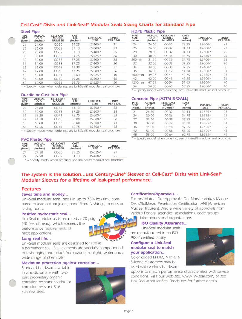
Cell-Cast@Disks and Link-Seal@Modular Seals Sizing Charts for Standard PipeSteel Pipe HDPE Plastic PipePIPE ACTUAL CELL-CAST CAST PIPE ACTUAL CELL-CAST CASTSIZE O.D. MODEL I.D. LINK-SEAL LINKS SIZE O.D. MODEL I.D. LINK-SEAL LINKS(Nom.) (Inches) NUMBER (Inches) SIZE PER SEAL (Nom.) (Inches) NUMBER (Inches) SIZE PER SEAL
24 24.00 ((-30 29.25 LS-500-* 21 24 24.00 ((-30 2925 LS-500-* 2 J26 26.00 ((-32 3 J. J3 LS-500-* 23 26 26.00 ((-32 3 J. J3 LS-500-* 2328 28.00 ((-32 3 J. J3 LS-400-* 25 28 28.00 ((-32 3 J. J3 LS-400-* 2530 30.00 ((-36 3475 LS-525-* 26 30 30.00 ((-36 34.75 LS-525-* 2632 3200 ((-38 3725 LS-500-* 28 800mm 3 J.50 ((-36 34.75 LS-400-* 2834 34.00 ((-38 37.25 LS-400-* 30 32 32.00 ((-38 37.25 LS-500-* 2836 36.00 ((-42 4 J .38 LS-500-* 3 J 34 34.00 ((-38 37.25 LS-400-* 3042 42.00 ((-48 47.25 LS-500-* 36 36 36.00 ((-42 41.38 LS-500-* 3 J48 48.00 ((-54 52.63 LS-525-* 40 1000mm 39.37 ((-44 43.75 LS-525-* 3354 54.00 ((-60 59.25 LS-500-* 46 42 42.00 ((-48 47.25 LS-500-* 3660 60.00 ((-66 64.75 LS-525-* 50 J200mm 47.24 ((-54 52.63 LS-500-* 40
* = SpecifY model when ordering. see Link-Seal@ modular seal brochure. 54 54.00 ((-60 59.25 LS-500-* 46* = SpecifY model when ordering, see Link-Seal@ modular seal brochure.
The system is the solution...use Century-Line@Sleeves or Cell-Cast@Disks with Link-Seal@Modular Sleeves for a lifetime of leak-proof performance.
FeaturesSaves time and money...Link-Sealmodular seals install in up to 75% less time com-pared to lead-oakum joints, hand fitted flC1shings,mastics orcasing boots.Positive hydrostatic seal...Link-Sealmodular seals are rated at 20 psig(40 feet of head), which exceeds theperformance requirements ofmost applications.long seal life...Link-Sealmodular seals are designed for use asa permanent seal. Seal elements are specially compoundedto resist aging and attack from ozone, sunlight, water and awide range of chemicals.Maximum protection against corrosion...Standard hardware availablein zinc-dicromate with two-part proprietary organiccorrosion resistant coating orcorrosion resistant 3 I6stainless steel.
Ductile or Cast Iron PipePIPE ACTUAL CELL-CAST CASTSIZE O.D. MODEL I.D. LINK-SEAL LINKS(Nom.) (Inches) NUMBER (Inches) SIZE PER SEAL
24 25.80 ((-32 31 13 LS-500-* 2330 3200 ((-38 3725 LS-500-* 2836 38.30 ((-44 43.75 LS-500-* 3342 44.50 ((-50 50.00 LS-500-* 3848 50.80 ((-56 56.00 LS-500-* 43
54 5756 ((-64 62.75 LS-500-* 48
* = SpecifY model when ordering, see Link-Seal@ modular seal brochure.
PYC Plastic PipePIPE ACTUAL CELL-CAST CASTSIZE O.D. MODEL I.D. LINK-SEAL LINKS(Nom.) (Inches) NUMBER (Inches) SIZE PER SEAL
24 24.80 ((-30 29.25 LS-525-* 2 J27 27.90 ((-32 31. J3 LS-400-* 25
* = SpecifY model when ordering, see Link-Seal@ modular seal brochure.
Concrete Pipe (ASTMB-WAll)PIPE ACTUAL CELL-CAST CASTSIZE O.D. MODEL I.D. LINK-SEAL LINKS(Nom.) (Inches) NUMBER (Inches) SIZE PER SEAL
21 26.50 ((-32 3 J.13 LS-525-* 2324 30.00 ((-36 34.75 LS-525-* 2627 33.50 ((-38 37.25 LS-400-* 3030 37.00 ((-42 41.38 LS-525-* 3 J36 4400 ((-48 47.25 LS-400-* 3942 5100 ((-56 56.00 LS-500-* 4348 5800 ((-64 62.75 LS-525-* 49
* = SpecifY model when ordering, see Link-Seal@ modular seal brochure.
Certification! Approvals...Factory Mutual FireApprovals. Det Norske Veritas MarineDeck/Bulkhead Penetration Certification. ANI (AmericanNuclear Insurers). Also a wide variety of approvals fromvarious Federal agencies, associations, code groups,
laboratories and organizations.ISO Quality Assurance...Link-Sealmodular seals
are manufactured in an ISO9002 certified facility.Configure a link-Sealmodular seal to matchyour application...Color coded EPDM, Nitrile, &Silicone elastomers may beused with various hardwareoptions to match performance characteristics with serviceconditions. Visitour web site, www.linkseal.com, or seeLink-SealModular Seal Brochures for further details.
Page4
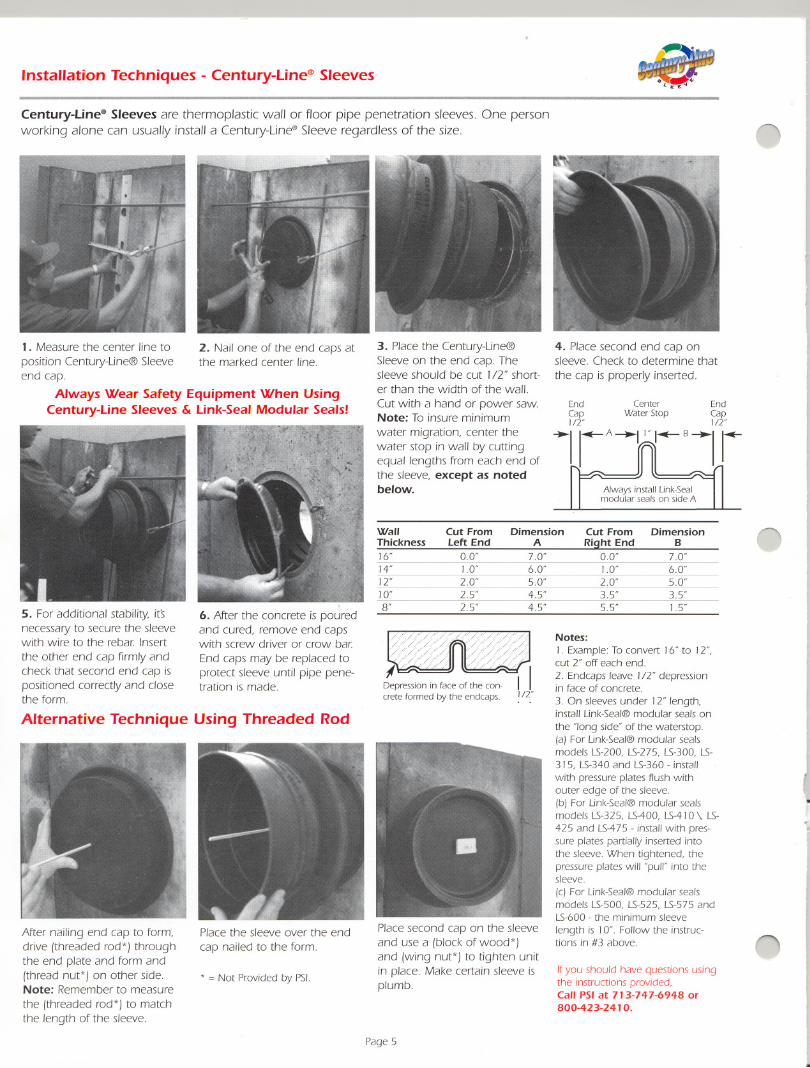
Installation Techniques - Century-Line@Sleeves
- -- - -
Century-Line@Sleeves are thermoplastic wall or floor pipe penetration sleeves. One personworking alone can usually install a Century-Line@Sleeve regardless of the size.
1. Measure the center line to
position Century-Line@Sleeveend cap.
Always Wear Safety Equipment When UsingCentury-Line Sleeves & Link-Seal Modular Seals!
5. For additional stability, itsnecessary to secure the sleevewith wire to the rebar Insert
the other end cap firmlyandcheck that second end cap ispositioned correctly and closethe form.
2. Nail one of the end caps atthe marked center line.
6. After the concrete is pouredand cured, remove end capswith screw driver or crow barEnd caps may be replaced toprotect sleeve until pipe pene-tration is made.
Alternative Technique Using Threaded Rod
After nailing end cap to form,drive (threaded rod*) throughthe end plate and form and(thread nut*) on other side.Note: Remember to measure
the (threaded rod*) to matchthe length of the sleeve.
Place the sleeve over the end
cap nailed to the form.
* = Not Provided by PSI.
3. Place the Century-Line@Sleeve on the end cap. Thesleeve should be cut 1/1" short-er than the width of the wall.Cut with a hand or power saw.Note: To insure minimum
water migration, center thewater stop in wall by cuttingequal lengths from each end ofthe sleeve, except as notedbelow.
n
4. Place second end cap onsleeve. Check to determine that
the cap is properly inserted.
End Center EndCap Water Stop CapIn" J"
~lrA~~B~lr
Always install Link-Sealmodular seals on side A
Depression in face of the con-crete formed by the endcaps.
Place second cap on the sleeveand use a (block of wood*)and (wing nut*) to tighten unitin place. Make certain sleeve isplumb.
Page 5
Notes:
I. Example: To convert 16" to 12'",cut 2'" off each end.
2. Endcaps leave 1/2'" depressionin face of concrete.
3. On sleeves under 12" length,install Link-Seal@ modular seals on
the "long side" of the waterstop.(a) For Link-Seal@ modular sealsmodels LS-200. LS-275. LS-300, LS-315, LS-340 and LS-360- install
with pressure plates flush withouter edge of the sleeve.rb) For Link-Seal@ modular sealsmodels LS-325, LS-400, LS-410 \ LS-
425 and LS-475 - install with pres-sure plates partially inserted intothe sleeve. When tightened, thepressure plates will "pull"' into thesleeve
rc) For Link-Seal@ modular sealsmodels LS-500, LS-525, LS-575 andLS-600 - the minimum sleeve
length is J0". Follow the instruc-tions in #3 above.
I
i
I
..r
nIfyou should have questions usingthe instructions provided,Call PSI at 713-747-6948 or800-423-2410.
,
Wall Cut From Dimension Cut From Dimension nThickness Left End A Right End B
16" 0.0" 70" 0.0" 70"14" 1.0" 60" 1.0" 6.0"12'" 2.0" 50" 2.0" 5.0"10" 2S 4S 3S 3S8" 2S 4S 5.5" IS
- -. - --
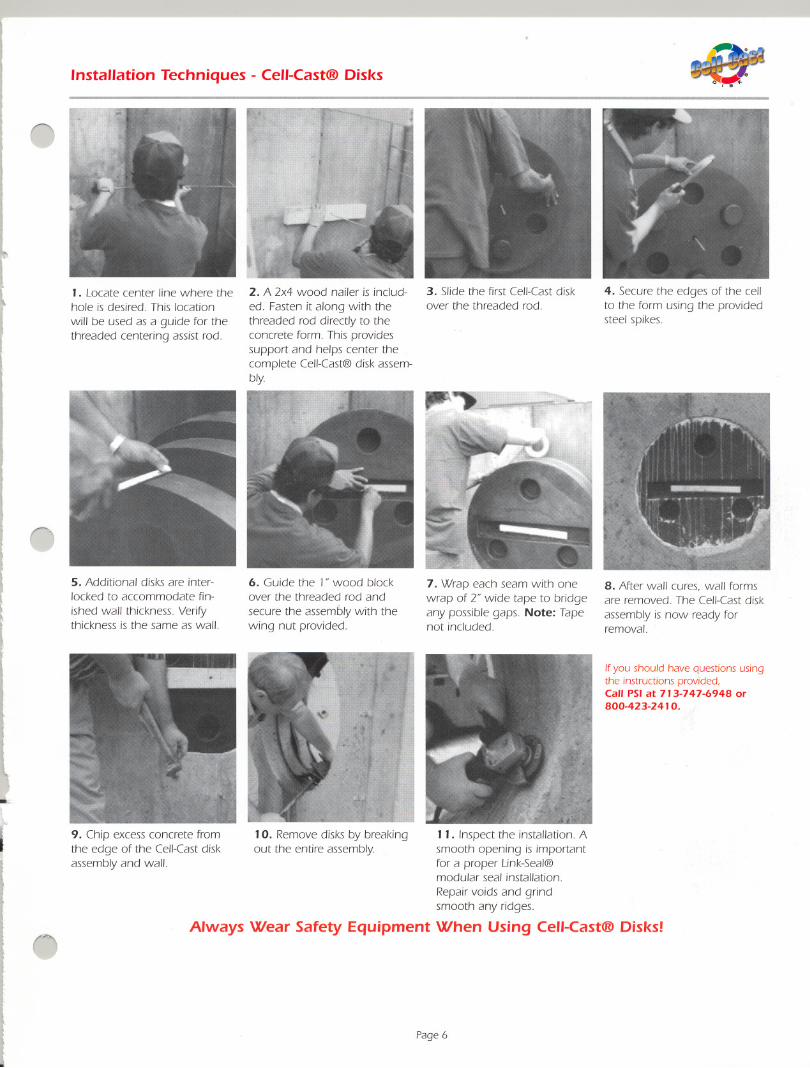
Installation Techniques - Cell-Cast@ Disks
0
~
1. Locate center line where thehole is desired. This location
will be used as a guide for thethreaded centering assist rod.
2. A 2x4 wood nailer is includ-ed. Fasten it along with thethreaded rod directly to theconcrete form. This providessupport and helps center thecomplete Cell-Cast@disk assem-bly.
n5. Additional disks are inter-locked to accommodate fin-
ished wall thickness. Veritythickness is the same as wall.
6. Guide the 1"wood blockover the threaded rod and
secure the assembly with thewing nut provided.
3. Slide the first Cell-Castdiskover the threaded rod.
7. Wrap each seam with onewrap of 2" wide tape to bridgeany possible gaps. Note: Tapenot included.
11. Inspect the installation. Asmooth opening is importantfor a proper Link-Seal@modular seal installation.
Repair voids and grindsmooth any ridges.
Always Wear Safety Equipment When Using Cell-Cast@ Disks!
-.
f9. Chip excess concrete fromthe edge of the Cell-Castdiskassembly and wall.
()
10. Remove disks by breakingout the entire assembly.
Page 6
4. Secure the edges of the cellto the form using the providedsteel spikes.
8. After wall cures, wall formsare removed. The Cell-Castdiskassembly is now ready forremoval.
Ifyou should have questions usingthe instructions provided,Call PSI at 713-747-6948 or800-423-2410.