plantpax logix batch and sequence manager reference manual€¢ files -- includes controller code,...
TRANSCRIPT

PlantPAx Logix Batch and Sequence Manager
Reference Manual
Version 4.0

Important User InformationRead this document and the documents listed in the additional resources section about installation, configuration, and operation of this equipment before you install, configure, operate, or maintain this product. Users are required to familiarize themselves with installation and wiring instructions in addition to requirements of all applicable codes, laws, and standards.
Activities including installation, adjustments, putting into service, use, assembly, disassembly, and maintenance are required to be carried out by suitably trained personnel in accordance with applicable code of practice.
If this equipment is used in a manner not specified by the manufacturer, the protection provided by the equipment may be impaired.
In no event will Rockwell Automation, Inc. be responsible or liable for indirect or consequential damages resulting from the use or application of this equipment.
The examples and diagrams in this manual are included solely for illustrative purposes. Because of the many variables and requirements associated with any particular installation, Rockwell Automation, Inc. cannot assume responsibility or liability for actual use based on the examples and diagrams.
No patent liability is assumed by Rockwell Automation, Inc. with respect to use of information, circuits, equipment, or software described in this manual.
Reproduction of the contents of this manual, in whole or in part, without written permission of Rockwell Automation, Inc., is prohibited.
Throughout this manual, when necessary, we use notes to make you aware of safety considerations.
Labels may also be on or inside the equipment to provide specific precautions.
WARNING: Identifies information about practices or circumstances that can cause an explosion in a hazardous environment, which may lead to personal injury or death, property damage, or economic loss.
ATTENTION: Identifies information about practices or circumstances that can lead to personal injury or death, property damage, or economic loss. Attentions help you identify a hazard, avoid a hazard, and recognize the consequence.
IMPORTANT Identifies information that is critical for successful application and understanding of the product.
SHOCK HAZARD: Labels may be on or inside the equipment, for example, a drive or motor, to alert people that dangerous voltage may be present.
BURN HAZARD: Labels may be on or inside the equipment, for example, a drive or motor, to alert people that surfaces may reach dangerous temperatures.
ARC FLASH HAZARD: Labels may be on or inside the equipment, for example, a motor control center, to alert people to potential Arc Flash. Arc Flash will cause severe injury or death. Wear proper Personal Protective Equipment (PPE). Follow ALL Regulatory requirements for safe work practices and for Personal Protective Equipment (PPE).

Table of Contents
PrefaceSoftware Compatibility and Content Revision. . . . . . . . . . . . . . . . . . . . 5Before You Begin. . . . . . . . . . . . . . . . . . . . . . . . . . . . . . . . . . . . . . . . . . . . . . . 6
Extract the LBSM Zip Files. . . . . . . . . . . . . . . . . . . . . . . . . . . . . . . . . . 7Install the Infrastructure . . . . . . . . . . . . . . . . . . . . . . . . . . . . . . . . . . . . 7
LBSM Faceplates . . . . . . . . . . . . . . . . . . . . . . . . . . . . . . . . . . . . . . . . . . . . . . . 8Quick Display . . . . . . . . . . . . . . . . . . . . . . . . . . . . . . . . . . . . . . . . . . . . . . 9Operator Tab . . . . . . . . . . . . . . . . . . . . . . . . . . . . . . . . . . . . . . . . . . . . . 10Manual Tab. . . . . . . . . . . . . . . . . . . . . . . . . . . . . . . . . . . . . . . . . . . . . . . 11Advanced (Engineering) Tab . . . . . . . . . . . . . . . . . . . . . . . . . . . . . . . 12
Additional Resources . . . . . . . . . . . . . . . . . . . . . . . . . . . . . . . . . . . . . . . . . . 13Logix Batch and Sequence Manager (LBSM)
Guidelines . . . . . . . . . . . . . . . . . . . . . . . . . . . . . . . . . . . . . . . . . . . . . . . . . . . . 16Functional Description . . . . . . . . . . . . . . . . . . . . . . . . . . . . . . . . . . . . . . . . 16Install the Components. . . . . . . . . . . . . . . . . . . . . . . . . . . . . . . . . . . . . . . . 17
Configure Controller Files . . . . . . . . . . . . . . . . . . . . . . . . . . . . . . . . . 17Incorporate LBSM into an HMI Application . . . . . . . . . . . . . . . . 20
Configure LBSM (size arrays) . . . . . . . . . . . . . . . . . . . . . . . . . . . . . . . . . . 30Modify the Data Structure . . . . . . . . . . . . . . . . . . . . . . . . . . . . . . . . . 30
Unit Configuration . . . . . . . . . . . . . . . . . . . . . . . . . . . . . . . . . . . . . . . . . . . 35User-defined Data Types . . . . . . . . . . . . . . . . . . . . . . . . . . . . . . . . . . . 36Operator Prompt . . . . . . . . . . . . . . . . . . . . . . . . . . . . . . . . . . . . . . . . . . 36
Phase Configuration. . . . . . . . . . . . . . . . . . . . . . . . . . . . . . . . . . . . . . . . . . . 37Configure a Master Recipe . . . . . . . . . . . . . . . . . . . . . . . . . . . . . . . . . . . . . 40
Setting Phase Parameters . . . . . . . . . . . . . . . . . . . . . . . . . . . . . . . . . . . 44Using Pause and Skip . . . . . . . . . . . . . . . . . . . . . . . . . . . . . . . . . . . . . . 45Built-in Phases . . . . . . . . . . . . . . . . . . . . . . . . . . . . . . . . . . . . . . . . . . . . 46
Create a Batch . . . . . . . . . . . . . . . . . . . . . . . . . . . . . . . . . . . . . . . . . . . . . . . . 51Save Master Recipe . . . . . . . . . . . . . . . . . . . . . . . . . . . . . . . . . . . . . . . . . . . . 53Connect Equipment to Controller Logic . . . . . . . . . . . . . . . . . . . . . . . . 55
PhaseManager Interface . . . . . . . . . . . . . . . . . . . . . . . . . . . . . . . . . . . . 56Bit Interface. . . . . . . . . . . . . . . . . . . . . . . . . . . . . . . . . . . . . . . . . . . . . . . 58Use the DN and State Bits. . . . . . . . . . . . . . . . . . . . . . . . . . . . . . . . . . 60
Operator Phase Control . . . . . . . . . . . . . . . . . . . . . . . . . . . . . . . . . . . . . . . 62Equipment Control . . . . . . . . . . . . . . . . . . . . . . . . . . . . . . . . . . . . . . . . . . . 65
Multi-Step Configuration . . . . . . . . . . . . . . . . . . . . . . . . . . . . . . . . . . 65Easy Recipe Configuration . . . . . . . . . . . . . . . . . . . . . . . . . . . . . . . . . 68
Start/Run Batch Demonstration . . . . . . . . . . . . . . . . . . . . . . . . . . . . . . . 69LBSM Help Displays . . . . . . . . . . . . . . . . . . . . . . . . . . . . . . . . . . . . . . 86
Appendix AAdvanced Capabilities PIContinue . . . . . . . . . . . . . . . . . . . . . . . . . . . . . . . . . . . . . . . . . . . . . . . 87
PIOwned . . . . . . . . . . . . . . . . . . . . . . . . . . . . . . . . . . . . . . . . . . . . . . . . . 88PIImmRel (immediate release). . . . . . . . . . . . . . . . . . . . . . . . . . . . . . 88Manual Generation of Batch ID . . . . . . . . . . . . . . . . . . . . . . . . . . . . 88
Rockwell Automation Publication PROCES-RM007C-EN-P - September 2018 3

Table of Contents
Appendix BEquipment Interface Codes Equipment Interface Codes . . . . . . . . . . . . . . . . . . . . . . . . . . . . . . . . 89
Appendix CBit Interface Examples ‘Add Ingredient’ Example . . . . . . . . . . . . . . . . . . . . . . . . . . . . . . . . . . 91
Run Until Done Example . . . . . . . . . . . . . . . . . . . . . . . . . . . . . . . . . . 92Run Until Stopped Example. . . . . . . . . . . . . . . . . . . . . . . . . . . . . . . . 94Run Until Done, Continue Until Stopped Example . . . . . . . . . . 96
Appendix DLBSM Reporting LBSM Report Data Structure . . . . . . . . . . . . . . . . . . . . . . . . . . . . . . . . . . 99
Retrieve Records . . . . . . . . . . . . . . . . . . . . . . . . . . . . . . . . . . . . . . . . . . . . . . 99Boolean Mechanism . . . . . . . . . . . . . . . . . . . . . . . . . . . . . . . . . . . . . . 100Integer Mechanism . . . . . . . . . . . . . . . . . . . . . . . . . . . . . . . . . . . . . . . 100Log on Demand . . . . . . . . . . . . . . . . . . . . . . . . . . . . . . . . . . . . . . . . . . 100
Appendix EHMI Security Codes HMI Security Codes. . . . . . . . . . . . . . . . . . . . . . . . . . . . . . . . . . . . . . 101
4 Rockwell Automation Publication PROCES-RM007C-EN-P - September 2018

Preface
This document applies to version 4.0 of the PlantPAx® Logix Batch and SequenceManager™ (LBSM). The LBSM application defines and stores recipes and sequences equipment and phases to make products.
Software Compatibility and Content Revision
The LBSM application can be downloaded from the Product Compatibility and Download Center at http://www.rockwellautomation.com/rockwellautomation/support/downloads.page.
The LBSM application version 4.0 is compatible with the following products:
• Logix 5000™ controller(1), firmware revision 18 or later• RSLogix 5000® software, version 18 or later• Studio 5000 Logix Designer® application, version 24.x• FactoryTalk® View Site Edition (SE) and FactoryTalk View Machine
Edition (ME) software, version 7.0 or later
Topic Page
Master Control Recipe Edits - Changed HMI and Table 36
Prompt section rewritten, New HMI 36
Incorporate LBSM into an HMI Application- Split step 11 into two steps 29
Modify Data Structure - Added steps to expand User-Defined folder 31, 32, 33, 34
Pause and Skip section was rewritten, new HMI 45
Wait Timer section rewritten, New HMI 50
Security information rewritten 101
(1) The CompactLogix™ 5370 L1 controller does not meet minimum CPU and memory requirements for the LBSM application. Verify your sizing requirements with the LBSM Memory Estimator that is included with the LBSM download. See Figure 2 on page 7.
Rockwell Automation Publication PROCES-RM007C-EN-P - September 2018 5

Preface
Before You Begin Familiarity with ISA-88 is helpful because LBSM uses constructs and terminology that is established in that standard. While the LBSM application can be used in non-batch equipment sequencing, we have chosen to use batch sequencing examples and ISA-88 terminology throughout this manual.
Figure 1 is the state model for LBSM procedure management.
Figure 1 - LBSM State Model
To implement an LBSM solution, we also suggest knowledge of the following:
• How to program Logix 5000 controllers with the Studio 5000 Logix Designer application
• How to use the Rockwell Automation® Library of Process Objects
6 Rockwell Automation Publication PROCES-RM007C-EN-P - September 2018

Preface
Extract the LBSM Zip Files
The LBSM_Vxx.yy.zz zip file that is downloaded with your LBSM application includes two folders:
• Documents -- Contains the LBSM Memory Estimator (a Microsoft Excel spreadsheet) to verify your sizing requirements for the controller
See Figure 2.• Files -- Includes controller code, graphics, sample project, and templates
Figure 2 - Sample LBSM Memory Calculator
Install the Infrastructure
The LBSM application file is designed as a standalone starting point for projects. The add-on capability lets you integrate the application into your existing controller project. To integrate the LBSM application into your application, see the following sections:
• Controller infrastructure – See page 17• HMI infrastructure – See page 20
Rockwell Automation Publication PROCES-RM007C-EN-P - September 2018 7
Preface
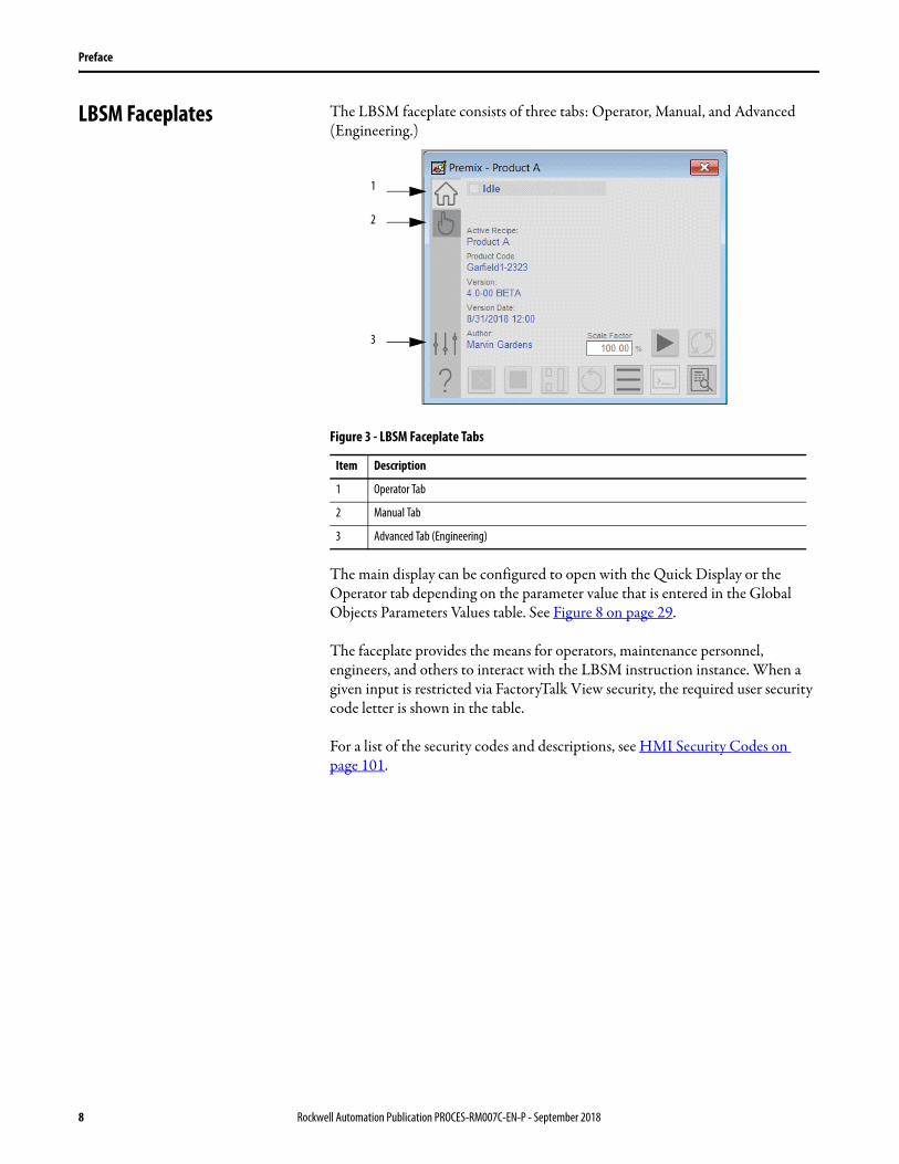
LBSM Faceplates The LBSM faceplate consists of three tabs: Operator, Manual, and Advanced (Engineering.)
Figure 3 - LBSM Faceplate Tabs
The main display can be configured to open with the Quick Display or the Operator tab depending on the parameter value that is entered in the Global Objects Parameters Values table. See Figure 8 on page 29.
The faceplate provides the means for operators, maintenance personnel, engineers, and others to interact with the LBSM instruction instance. When a given input is restricted via FactoryTalk View security, the required user security code letter is shown in the table.
For a list of the security codes and descriptions, see HMI Security Codes on page 101.
Item Description
1 Operator Tab
2 Manual Tab
3 Advanced Tab (Engineering)
1
2
3
8 Rockwell Automation Publication PROCES-RM007C-EN-P - September 2018

Preface
Quick Display
The Quick Display screen provides means for operators to perform key interactions with the LBSM application. From the Quick Display, you can navigate to the faceplate for full access for operation, maintenance, and configuration. Press the Home button to navigate to the full faceplate.
Rockwell Automation Publication PROCES-RM007C-EN-P - September 2018 9

Preface
Operator Tab
The control buttons on the LBSM application let you run a batch from this tab. In addition, the Operator tab shows the following information:
• Current state• What phase the sequence is waiting on and how much time remains• Manual prompt attention
Current step and wait timer in sequence, if applicable
Figure 4 - Operator Tab Description
Figure 5 - Operator Tab Description
Item Description
1 Abort sequence
2 Stop sequence
3 Hold sequence
4 Start or resume sequence
5 Reset sequence
6 Access the runtime detail faceplate
7 Respond to Operator prompt
8 Load a sequence from the master sequence list
9 Restart sequence
123
4
5
6
789
10 Rockwell Automation Publication PROCES-RM007C-EN-P - September 2018
Preface
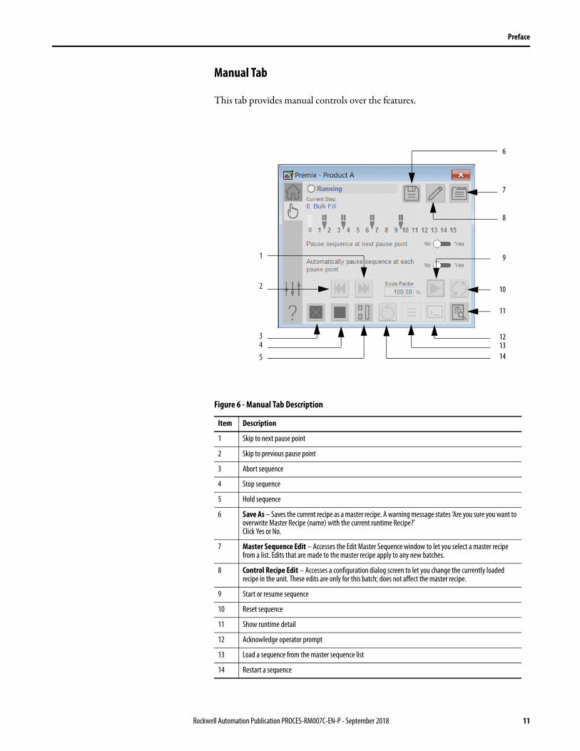
Manual Tab
This tab provides manual controls over the features.
Figure 6 - Manual Tab Description
Item Description
1 Skip to next pause point
2 Skip to previous pause point
3 Abort sequence
4 Stop sequence
5 Hold sequence
6 Save As – Saves the current recipe as a master recipe. A warning message states ‘Are you sure you want to overwrite Master Recipe (name) with the current runtime Recipe?’ Click Yes or No.
7 Master Sequence Edit – Accesses the Edit Master Sequence window to let you select a master recipe from a list. Edits that are made to the master recipe apply to any new batches.
8 Control Recipe Edit – Accesses a configuration dialog screen to let you change the currently loaded recipe in the unit. These edits are only for this batch; does not affect the master recipe.
9 Start or resume sequence
10 Reset sequence
11 Show runtime detail
12 Acknowledge operator prompt
13 Load a sequence from the master sequence list
14 Restart a sequence
8
6
7
1
4
2
3
9
10
5
11
121314
Rockwell Automation Publication PROCES-RM007C-EN-P - September 2018 11
Preface
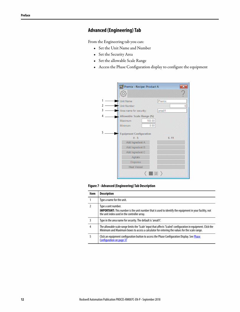
Advanced (Engineering) Tab
From the Engineering tab you can:• Set the Unit Name and Number• Set the Security Area• Set the allowable Scale Range• Access the Phase Configuration display to configure the equipment
Figure 7 - Advanced (Engineering) Tab Description
Item Description
1 Type a name for the unit.
2 Type a unit number.IMPORTANT: This number is the unit number that is used to identify the equipment in your facility, not the unit index used in the controller array.
3 Type in the area name for security. The default is ‘area01’.
4 The allowable scale range limits the 'Scale' input that affects 'Scaled' configuration in equipment. Click the Minimum and Maximum boxes to access a calculator for entering the values for the scale range.
5 Click an equipment configuration button to access the Phase Configuration Display. See Phase Configuration on page 37
1
4
23
5
12 Rockwell Automation Publication PROCES-RM007C-EN-P - September 2018
Preface
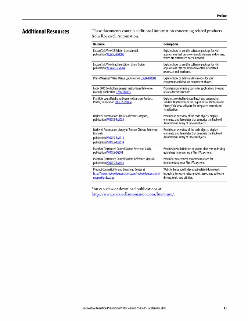
Additional Resources These documents contain additional information concerning related products from Rockwell Automation.
You can view or download publications at http://www.rockwellautomation.com/literature/.
Resource Description
FactoryTalk View SE Edition User Manual, publication VIEWSE-UM006
Explains how to use this software package for HMI applications that can involve multiple users and servers, which are distributed over a network.
FactoryTalk View Machine Edition User's Guide, publication VIEWME-UM004
Explains how to use this software package for HMI applications that monitor and control automated processes and machines.
PhaseManager™ User Manual, publication LOGIX-UM001 Explains how to define a state model for your equipment and develop equipment phases.
Logix 5000 Controllers General Instructions Reference Manual, publication 1756-RM003
Provides programming controller applications by using relay ladder instructions.
PlantPAx Logix Batch and Sequence Manager Product Profile, publication PROCES-PP004
Explains a controller-based batch and sequencing solution that leverages the Logix Control Platform and
FactoryTalk View software for integrated control and visualization.
Rockwell Automation® Library of Process Objects, publication PROCES-RM002
Provides an overview of the code objects, display elements, and faceplates that comprise the Rockwell Automation Library of Process Objects.
Rockwell Automation Library of Process Objects Reference Manuals:publication PROCES-RM013publication PROCES-RM014
Provides an overview of the code objects, display elements, and faceplates that comprise the Rockwell Automation Library of Process Objects.
PlantPAx Distributed Control System Selection Guide, publication PROCES-SG001
Provides basic definitions of system elements and sizing guidelines for procuring a PlantPAx system.
PlantPAx Distributed Control System Reference Manual, publication PROCES-RM001
Provides characterized recommendations for implementing your PlantPAx system.
Product Compatibility and Download Center at http://www.rockwellautomation.com/rockwellautomation/support/pcdc.page
Website helps you find product-related downloads including firmware, release notes, associated software, drivers, tools, and utilities.
Rockwell Automation Publication PROCES-RM007C-EN-P - September 2018 13

Preface
Notes:
14 Rockwell Automation Publication PROCES-RM007C-EN-P - September 2018

Logix Batch and Sequence Manager (LBSM)
The PlantPAx® Logix Batch and SequenceManager™ (LBSM) application provides batch-process management functionality. A Logix controller and FactoryTalk® View software are the only requirements for configuration and execution. This solution lets you start small with a finite number of recipes, but easily scales into a server-based system without costly re-engineering and testing.
The ability of the LBSM application to sequence phases or equipment with or without Logix PhaseManager™ software provides a platform that you can use in nearly any application. Logix PhaseManager software permits seamless migration from LBSM to FactoryTalk Batch software.
The global object and faceplate that are shown are examples of the graphical interface tools for this standalone application.
Rockwell Automation Publication PROCES-RM007C-EN-P - September 2018 15
Logix Batch and Sequence Manager (LBSM)
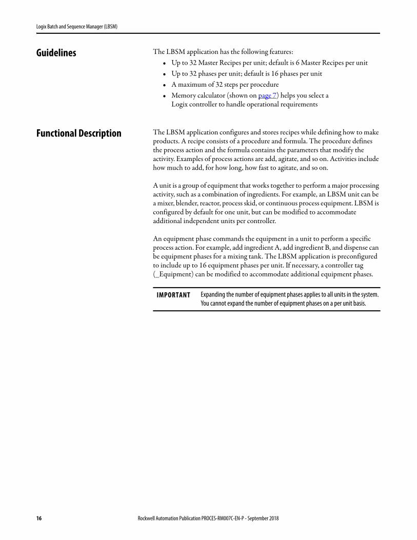
Guidelines The LBSM application has the following features:• Up to 32 Master Recipes per unit; default is 6 Master Recipes per unit• Up to 32 phases per unit; default is 16 phases per unit• A maximum of 32 steps per procedure• Memory calculator (shown on page 7) helps you select a
Logix controller to handle operational requirements
Functional Description The LBSM application configures and stores recipes while defining how to make products. A recipe consists of a procedure and formula. The procedure defines the process action and the formula contains the parameters that modify the activity. Examples of process actions are add, agitate, and so on. Activities include how much to add, for how long, how fast to agitate, and so on.
A unit is a group of equipment that works together to perform a major processing activity, such as a combination of ingredients. For example, an LBSM unit can be a mixer, blender, reactor, process skid, or continuous process equipment. LBSM is configured by default for one unit, but can be modified to accommodate additional independent units per controller.
An equipment phase commands the equipment in a unit to perform a specific process action. For example, add ingredient A, add ingredient B, and dispense can be equipment phases for a mixing tank. The LBSM application is preconfigured to include up to 16 equipment phases per unit. If necessary, a controller tag
(_Equipment) can be modified to accommodate additional equipment phases.
IMPORTANT Expanding the number of equipment phases applies to all units in the system. You cannot expand the number of equipment phases on a per unit basis.
16 Rockwell Automation Publication PROCES-RM007C-EN-P - September 2018
Logix Batch and Sequence Manager (LBSM)
Install the Components To begin the process, download the LBSM zip files from the Product Compatibility and Download Center at http://www.rockwellautomation.com/rockwellautomation/support/downloads.page.
You must install one of two LBSM applications that are included in the download file set:
• Components with Journal• Components No Journal (smaller footprint without reporting)
See page 7 for a description of the zip folder contents.
Configure Controller Files
This section describes how to install the controller files. You have
two options:• Integrate the LBSM application into your existing application• Start a new project with the templates provided in the download
– LBSM_Template_No_Journal.ACD– LBSM_Template_with_Journal.ACD
Complete these steps only for integrating the LBSM application into an
existing Studio 5000 Logix Designer® project. The supplied templates for a new project contain the necessary tasks.
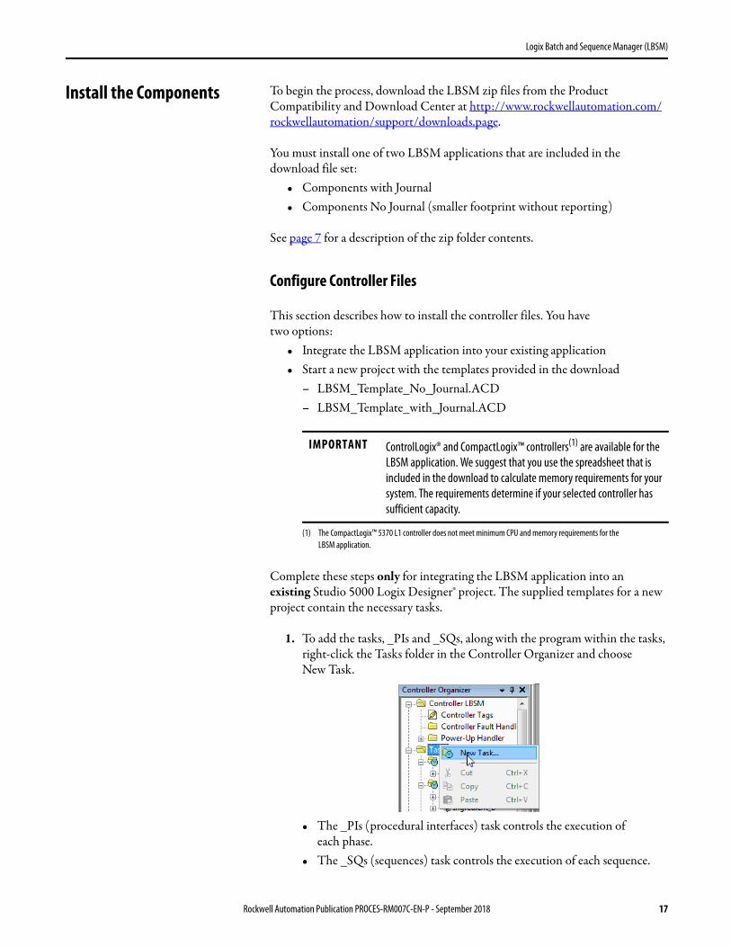
1. To add the tasks, _PIs and _SQs, along with the program within the tasks, right-click the Tasks folder in the Controller Organizer and choose
New Task.
• The _PIs (procedural interfaces) task controls the execution of each phase.
• The _SQs (sequences) task controls the execution of each sequence.
IMPORTANT ControlLogix® and CompactLogix™ controllers(1) are available for the LBSM application. We suggest that you use the spreadsheet that is included in the download to calculate memory requirements for your system. The requirements determine if your selected controller has sufficient capacity.
(1) The CompactLogix™ 5370 L1 controller does not meet minimum CPU and memory requirements for the
LBSM application.
Rockwell Automation Publication PROCES-RM007C-EN-P - September 2018 17
Logix Batch and Sequence Manager (LBSM)
• The codes within the routines are locked from the user.
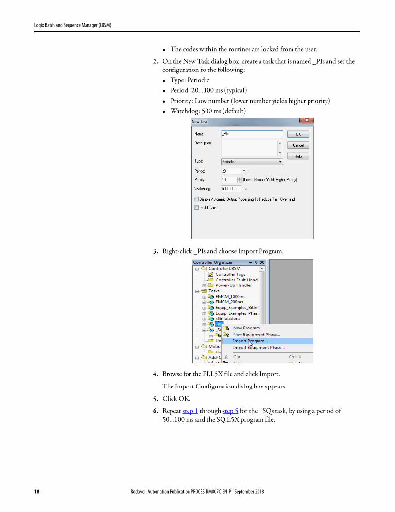
2. On the New Task dialog box, create a task that is named _PIs and set the configuration to the following:• Type: Periodic• Period: 20…100 ms (typical)• Priority: Low number (lower number yields higher priority)• Watchdog: 500 ms (default)
3. Right-click _PIs and choose Import Program.
4. Browse for the PI.L5X file and click Import.
The Import Configuration dialog box appears.
5. Click OK.
6. Repeat step 1 through step 5 for the _SQs task, by using a period of 50…100 ms and the SQ.L5X program file.
18 Rockwell Automation Publication PROCES-RM007C-EN-P - September 2018

Logix Batch and Sequence Manager (LBSM)
7. To add the EM_LBSM Add-On Instruction to your project, right-click the Add-On Instructions folder and choose Import Add-On Instruction.
The Import Add-On Instruction dialog box appears.
8. Select the EM_LBSM.L5X Add-On Instruction and click Import.
9. On the Import Configuration dialog box, click OK.
The controller scope tags in the Controller Scope Tags table are added to your Logix project. By default, the following tags are available:• One unit• 16 equipment phases per unit• Six master recipes per unit
To modify array sizes, if necessary, see Table 5 on page 36.
IMPORTANT You must use the EM_LBSM Add-On Instruction in each equipment module that you create. This Add-On Instruction manages the equipment module modes and handshakes to the rest of the system.
Rockwell Automation Publication PROCES-RM007C-EN-P - September 2018 19
Logix Batch and Sequence Manager (LBSM)
Incorporate LBSM into an HMI Application
You must import the visualization files that are associated with and included in the LBSM download. The files are included in the download from the Product Compatibility and Download Center at http://www,rockwellautomation.com/rockwellautomation/support/pcdc.page.
Images are external graphic files that can be used in displays. They must be imported for FactoryTalk View to use them.
Upon import, PNG files are renamed by FactoryTalk View with a .bmp file extension, but retain a .png format.
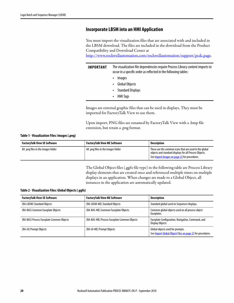
The Global Object files (.ggfx file type) in the following table are Process Library display elements that are created once and referenced multiple times on multiple displays in an application. When changes are made to a Global Object, all instances in the application are automatically updated.
IMPORTANT The visualization file dependencies require Process Library content imports to occur in a specific order as reflected in the following tables:• Images• Global Objects• Standard Displays• HMI Tags
Table 1 - Visualization Files: Images (.png)
FactoryTalk View SE Software FactoryTalk View ME Software Description
All .png files in the images folder All .png files in the images folder These are the common icons that are used in the global objects and standard displays for all Process Objects.See Import Images on page 22 for procedures.
Table 2 - Visualization Files: Global Objects (.ggfx)
FactoryTalk View SE Software FactoryTalk View ME Software Description
(RA-LBSM) Standard Objects (RA-LBSM-ME) Standard Objects Standard global used on Sequencer displays.
(RA-BAS) Common Faceplate Objects (RA-BAS-ME) Common Faceplate Objects Common global objects used on all process object faceplates.
(RA-BAS) Process Faceplate Common Objects (RA-BAS-ME) Process Faceplate Common Objects Faceplate Configuration, Navigation, Command, and Display Objects
(RA-UI) Prompt Objects (RA-UI-ME) Prompt Objects Global objects used for prompts.See Import Global Object Files on page 23 for procedures.
20 Rockwell Automation Publication PROCES-RM007C-EN-P - September 2018

Logix Batch and Sequence Manager (LBSM)
The Standard Display files (.gfx file type) in the following table are the Process Library displays that you see at runtime.
Table 3 - Visualization Files: Standard Displays (.gfx)
FactoryTalk View SE Software FactoryTalk View ME Software Description
(RA-LBSM) Equipment-Config (RA-LBSM-ME) Equipment-Config Configuration display used to configure the equipment phase.
(RA-LBSM) Equipment-Faceplate (RA-LBSM-ME) Equipment-Faceplate Faceplate used for the equipment module.
(RA-LBSM) MasterSeq-Edit-Select (RA-LBSM-ME) MasterSeq-Edit-Select Selection display used to select the Master Sequence to edit.
(RA-LBSM) MasterSeq-Load-Select (RA-LBSM-ME) MasterSeq-Load-Select Selection display used to select the Master Sequence to load into the runtime tags.
(RA-LBSM) Phase-Faceplate (RA-LBSM-ME) Phase-Faceplate Faceplate used to run the phases in a sequence.
(RA-LBSM) Sequence-Config (RA-LBSM) Sequence-Config (RA-LBSM) Sequence-Config2 (RA-LBSM) Sequence-Config3
Configuration display used to configure the unit and phases in the sequence.
— (RA-LBSM-ME) Sequence-Config-Step-Confirm Confirmation display used to verify the requested 'Delete Step', 'Copy Step', and 'Insert Step' commands.
(RA-LBSM) Sequence-Config-Easy — Configuration display used to enable or disable phases for multiple steps in a sequence.
(RA-LBSM) Sequence-Config-Step (RA-LBSM-ME) Sequence-Config-Step Configuration display used to configure one step in a sequence.
(RA-LBSM) Sequence-Config-MultiStep (RA-LBSM-ME) Sequence-Config-MultiStep Configuration display used to configure attributes for multiple steps in a sequence.
(RA-LBSM) Sequence-Config-PhaseStep (RA-LBSM-ME) Sequence-Config-PhaseStep Configuration display used to configure the instance of a phase and step in a sequence.
(RA-LBSM) Sequence-Detail (RA-LBSM-ME) Sequence-Detail Faceplate used to show Run Time Detail of a sequence.
(RA-LBSM) Sequence-Faceplate (RA-LBSM-ME) Sequence-Faceplate The Sequence faceplate used for the object.
(RA-LBSM) Sequence-Help (RA-LBSM-ME) Sequence-Help Help information that is accessed from the sequence faceplate.
(RA-LBSM) Sequence-Quick (RA-LBSM-ME) Sequence-Quick The Quick display used for the object.
(RA-LBSM) Sequence-RunTime-PhaseValues (RA-LBSM-ME) Sequence-RunTime-PhaseValues Display used to show the phase values for one step in the runtime sequence.
(RA-LBSM) Sequence-RunTime-SaveAs-Confirm (RA-LBSM-ME) Sequence-RunTime-SaveAs-Confirm Confirmation display used to verify a master sequence overwrite during the requested 'Save As Master Sequence' command.
(RA-LBSM) Sequence-RunTime-SaveAs-Select (RA-LBSM-ME) Sequence-RunTime-SaveAs-Select Display used to select a Master Sequence location for the runtime sequence.
— (RA-LBSM-ME) Sequence-RunTime-Confirm Confirmation display used to verify the requested 'Sequence Stop' or 'Sequence Abort' command.
(RA-UI) P_Prompt-Config (RA-UI-ME) P_Prompt-Config Display used to configure the prompt.
(RA-UI) P_Prompt-Response (RA-UI-ME) P_Prompt-Response Display used to complete the operator prompt.
(RA-UI) P_Prompt-Select (RA-UI-ME) P_Prompt-Select Display used to select a prompt for the sequence step.
Rockwell Automation Publication PROCES-RM007C-EN-P - September 2018 21

Logix Batch and Sequence Manager (LBSM)
HMI Tags are created in a FactoryTalk View ME application to support tab switching on Process Library faceplates. The HMI tags can be imported via the comma-separated values file (.csv file type) in the following table.
Import Images
Complete these steps to add the common icons (images) for the global objects and faceplates for the HMI application.
1. In the FactoryTalk View Studio software, expand the Graphics folder in the Explorer™ window.
2. Right-click Images and choose Add Component Into Application.
The Add Component Into Project dialog box appears.
3. Browse to your downloaded graphics folder.
Table 4 - Visualization Files: HMI Tags (.csv)
FactoryTalk View SE Software FactoryTalk View ME Software Description
FTViewSE_ProcessLibrary_Tags_4_0_xx.CSV FTViewME_ProcessLibrary_Tags_4_0_xx.CSV These tags must be imported into the FactoryTalk View
SE/ME project to support the LBSM displays.See Add HMI Tags to the Application on page 26 for procedures.
22 Rockwell Automation Publication PROCES-RM007C-EN-P - September 2018

Logix Batch and Sequence Manager (LBSM)
4. Open the graphics folder and double-click the Images folder.
5. Click the pull-down menu (as circled) and select a file type.
For example, PNG Images (*.png)
6. Click Ctrl-A to highlight all .png images.
7. Click Open to import the images.
Import Global Object Files
Global objects serve two purposes:• Faceplate objects files contain common elements that are used in building
faceplate displays.• Graphics Library files contain device symbols that you can use to build
your application displays. Clicking the symbol opens the corresponding faceplate displays.
1. In the FactoryTalk View Studio software, expand the Graphics folder in the Explorer window.
IMPORTANT Change the path to the image folder and the file type to PNG. PNG files provide more control with transparency.
Rockwell Automation Publication PROCES-RM007C-EN-P - September 2018 23

Logix Batch and Sequence Manager (LBSM)
2. Right-click Global Objects and choose Add Component Into Application.
The Add Component Into Project dialog box appears.
3. Browse to your downloaded graphics folder.
4. Open the graphics folder and double-click the FTView SE folder.
5. Double-click Global Objects.
6. Select all .ggfx files and click Open to import the three LBSM global objects as shown.
24 Rockwell Automation Publication PROCES-RM007C-EN-P - September 2018

Logix Batch and Sequence Manager (LBSM)
Import HMI Displays
LBSM displays depict a batch procedure. Complete these steps to import displays.
1. Right-click Displays and choose Add Component Into Application.
The Add Component Into Project dialog box appears.
2. Browse to your downloaded graphics folder.
3. Open the graphics folder and double-click the FTView SE folder.
4. Double-click GFX and select all *.gfx files.
5. Click Open.
Rockwell Automation Publication PROCES-RM007C-EN-P - September 2018 25
Logix Batch and Sequence Manager (LBSM)
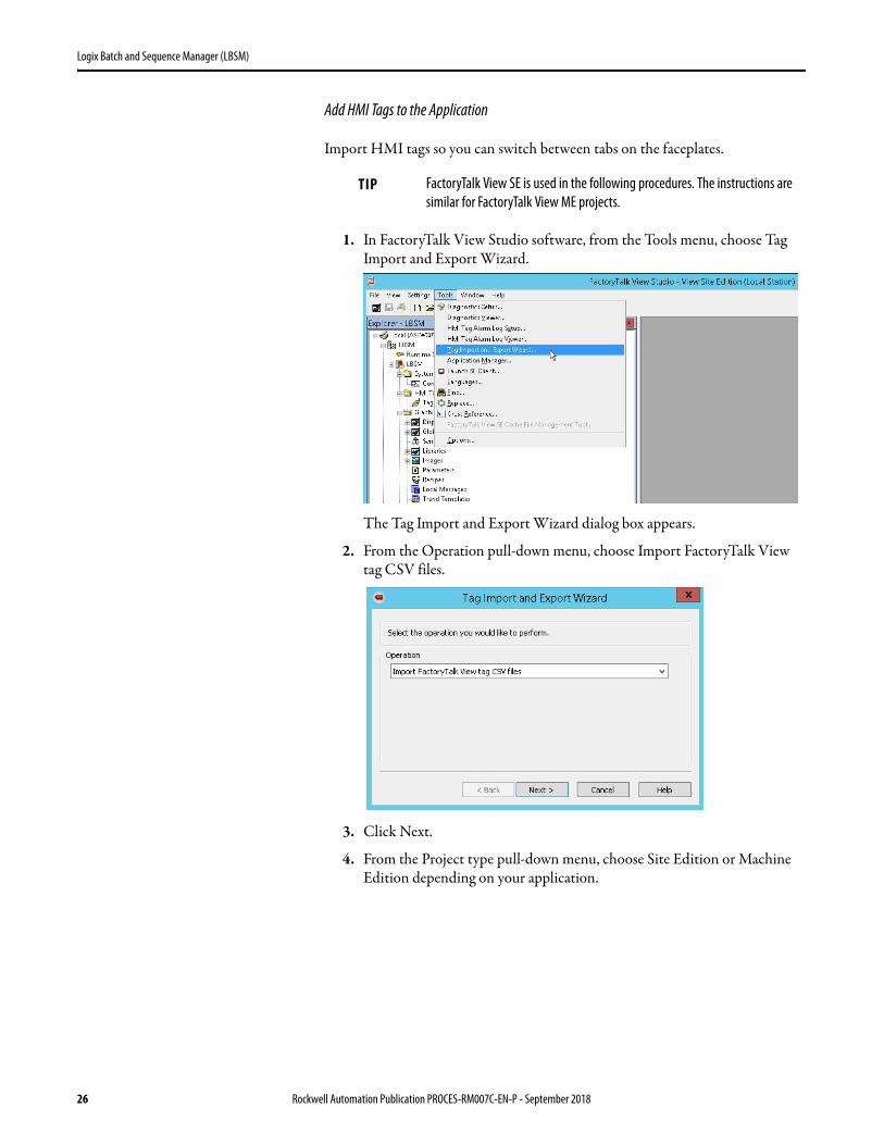
Add HMI Tags to the Application
Import HMI tags so you can switch between tabs on the faceplates.
1. In FactoryTalk View Studio software, from the Tools menu, choose Tag Import and Export Wizard.
The Tag Import and Export Wizard dialog box appears.
2. From the Operation pull-down menu, choose Import FactoryTalk View tag CSV files.
3. Click Next.
4. From the Project type pull-down menu, choose Site Edition or Machine Edition depending on your application.
TIP FactoryTalk View SE is used in the following procedures. The instructions are similar for FactoryTalk View ME projects.
26 Rockwell Automation Publication PROCES-RM007C-EN-P - September 2018

Logix Batch and Sequence Manager (LBSM)
5. Browse for and select your FactoryTalk View SE project file, and then click Next.
6. Check Tags
7. Browse for and select the RAProcessLibrary-Tags.CSV file, and then
click Next
8. Click Skip existing (fastest), and then click Next.
9. Click Finish to import the HMI files.
Rockwell Automation Publication PROCES-RM007C-EN-P - September 2018 27
Logix Batch and Sequence Manager (LBSM)
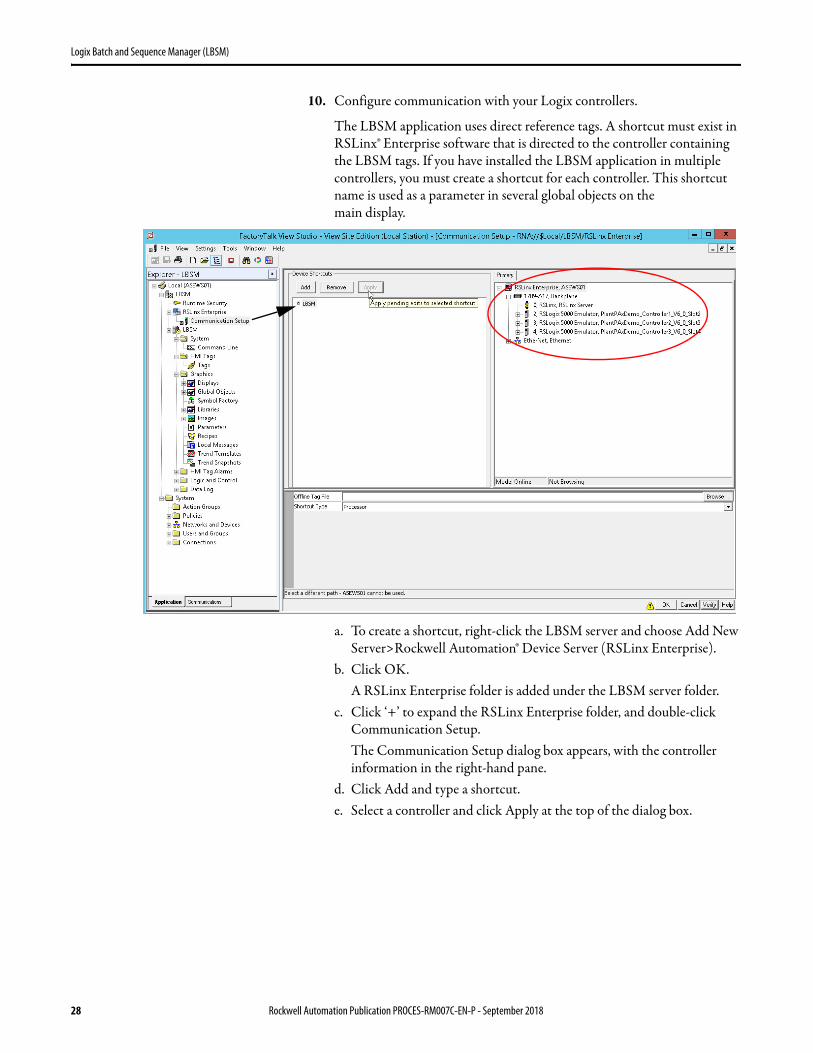
10. Configure communication with your Logix controllers.
The LBSM application uses direct reference tags. A shortcut must exist in RSLinx® Enterprise software that is directed to the controller containing the LBSM tags. If you have installed the LBSM application in multiple controllers, you must create a shortcut for each controller. This shortcut name is used as a parameter in several global objects on the
main display.
a. To create a shortcut, right-click the LBSM server and choose Add New Server>Rockwell Automation® Device Server (RSLinx Enterprise).
b. Click OK.A RSLinx Enterprise folder is added under the LBSM server folder.
c. Click ‘+’ to expand the RSLinx Enterprise folder, and double-click Communication Setup.The Communication Setup dialog box appears, with the controller information in the right-hand pane.
d. Click Add and type a shortcut.e. Select a controller and click Apply at the top of the dialog box.
28 Rockwell Automation Publication PROCES-RM007C-EN-P - September 2018
Logix Batch and Sequence Manager (LBSM)
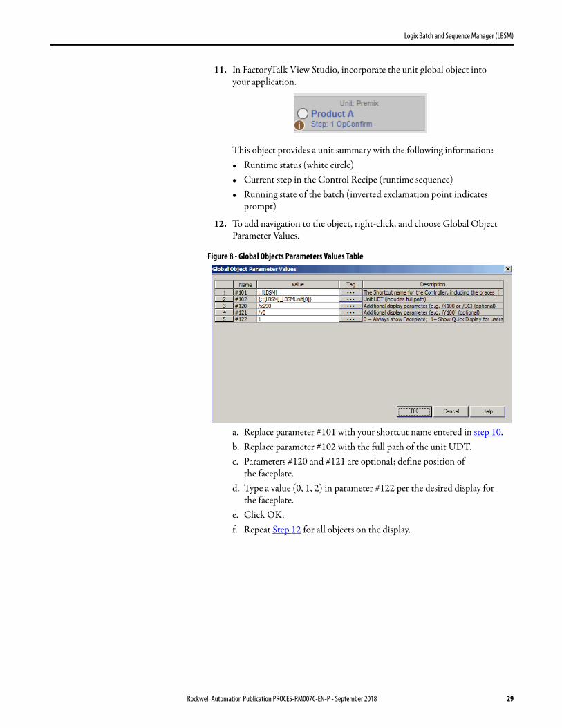
11. In FactoryTalk View Studio, incorporate the unit global object into
your application.
This object provides a unit summary with the following information:• Runtime status (white circle)• Current step in the Control Recipe (runtime sequence)• Running state of the batch (inverted exclamation point indicates
prompt)
12. To add navigation to the object, right-click, and choose Global Object Parameter Values.
Figure 8 - Global Objects Parameters Values Table
a. Replace parameter #101 with your shortcut name entered in step 10.b. Replace parameter #102 with the full path of the unit UDT.c. Parameters #120 and #121 are optional; define position of
the faceplate.d. Type a value (0, 1, 2) in parameter #122 per the desired display for
the faceplate.e. Click OK.f. Repeat Step 12 for all objects on the display.
Rockwell Automation Publication PROCES-RM007C-EN-P - September 2018 29

Logix Batch and Sequence Manager (LBSM)
Configure LBSM (size arrays) You can size arrays for the elements that comprise the application, such as the maximum number of units, equipment phases, sequence steps, and so on. The size of your recipe/sequence affects the amount of memory that is required for the controller that operates your application. For example, four units with 16 phases each requires more memory usage than two units with five phases per unit.
Therefore, to make sure that you have the correct controller with sufficient memory, you must first identify the units in your application. A unit is a group of equipment that works together to perform a major processing activity.
Modify the Data Structure
The LBSM ACD file, which is included with the download, has User-defined Data Types (UDT) that contain arrays. The arrays let you enter a numeric value to modify the size. For example, the LBSM_Unit[6] UDT indicates that there are six independent units for a project.
These four UDTs determine the following arrays (up to system maximums) for your application:
• LBSM_Unit – Number of units in the project• LBSM_Equipment – Number of phases per unit• LBSM_SQm – Number of master recipes per unit• LBSM_SQ_Config – Number of steps and prompts per sequence
Number of Units
Complete these steps to set the number of units.
1. Open the LBSM ACD file in the Logix Designer application and double-click Controller Tags in the left Controller Organizer pane.
The tags appear in the right pane.
IMPORTANT If multiple units reside in a controller, assign each unit a unique number, starting with zero. This number correlates your equipment with a specific array memory location in the controller. This correlation is essential for implementing the logic to run your equipment. See page 55 for more information.
30 Rockwell Automation Publication PROCES-RM007C-EN-P - September 2018
Logix Batch and Sequence Manager (LBSM)
2. In the Data Type column, change the value in the brackets for the LBSM_Unit[x] UDT.
3. Click File>Save.
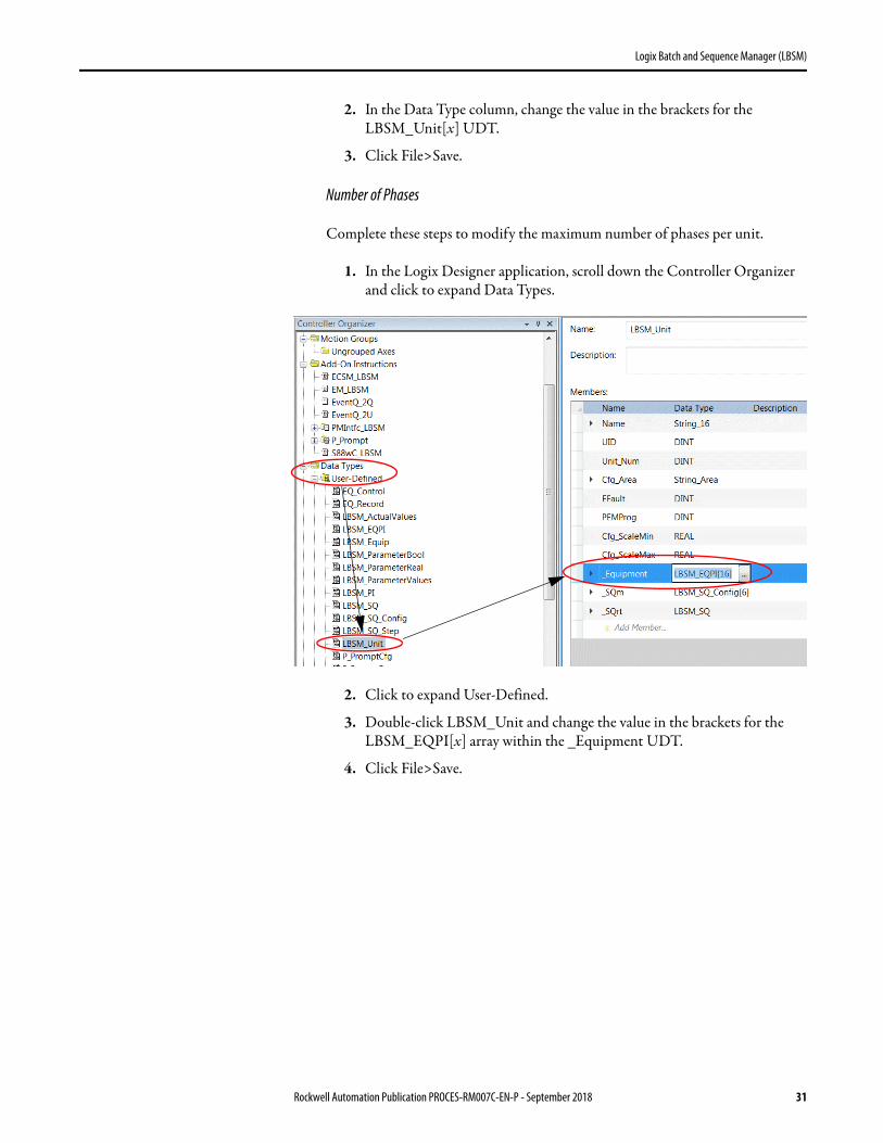
Number of Phases
Complete these steps to modify the maximum number of phases per unit.
1. In the Logix Designer application, scroll down the Controller Organizer and click to expand Data Types.
2. Click to expand User-Defined.
3. Double-click LBSM_Unit and change the value in the brackets for the LBSM_EQPI[x] array within the _Equipment UDT.
4. Click File>Save.
Rockwell Automation Publication PROCES-RM007C-EN-P - September 2018 31

Logix Batch and Sequence Manager (LBSM)
Number of Recipes
Complete these steps to modify the maximum number of recipes per unit.
1. In the Logix Designer application, scroll down the Controller Organizer and click to expand Data Types.
2. Click to expand User-Defined.
3. Double-click LBSM_Unit and change the value in the brackets for the LBSM_SQ_Config[x] array within the _SQm UDT.
4. Click File>Save.
32 Rockwell Automation Publication PROCES-RM007C-EN-P - September 2018
Logix Batch and Sequence Manager (LBSM)
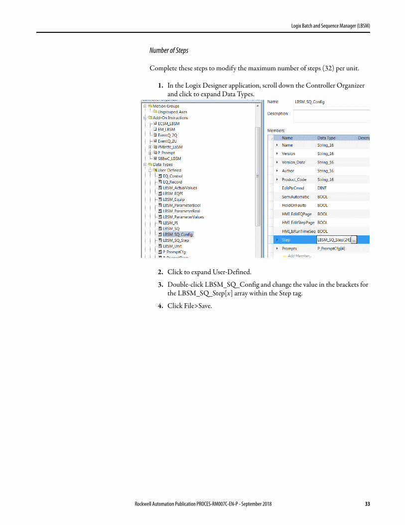
Number of Steps
Complete these steps to modify the maximum number of steps (32) per unit.
1. In the Logix Designer application, scroll down the Controller Organizer and click to expand Data Types.
2. Click to expand User-Defined.
3. Double-click LBSM_SQ_Config and change the value in the brackets for the LBSM_SQ_Step[x] array within the Step tag.
4. Click File>Save.
Rockwell Automation Publication PROCES-RM007C-EN-P - September 2018 33

Logix Batch and Sequence Manager (LBSM)
Number of Prompts
Complete these steps to modify the maximum number of prompts per unit.
1. In the Logix Designer application, scroll down the Controller Organizer and click to expand Data Types.
2. Click to expand User-Defined.
3. Double-click LBSM_SQ_Config and change the value in the brackets for the P_PromptCfg[x] array within the Prompts tag.
4. Click File>Save.
34 Rockwell Automation Publication PROCES-RM007C-EN-P - September 2018

Logix Batch and Sequence Manager (LBSM)
Unit Configuration After you have sized the arrays, you are ready to configure a unit in your LBSM application. You must have engineering configuration security to modify the unit configuration.
1. On the Operator tab, click the Display Advanced Properties button.
The Engineering tab appears.
Rockwell Automation Publication PROCES-RM007C-EN-P - September 2018 35

Logix Batch and Sequence Manager (LBSM)
2. Configure the unit on the Engineering tab faceplate.
User-defined Data Types
These LBSM_Unit user-defined data types (UDTs) define the number of equipment phases per unit (_Equipment) and the number of master recipes (_SQm) in each unit; 32 maximum.
The maximum step count per phase is 32; there is no step array.
Operator Prompt
An embedded prompt instruction is included with the LBSM ACD file to perform prompting. The prompt lets an operator interact with a running phase in various ways, including entering values, verifying data, or providing directions to perform a task.
The number of manual prompts available for a unit is configurable, up to 32. The default number is four.
Table 5 - Unit Configuration Description
Topic Description
Unit Name Type a name for the unit.
Unit Number Type a unit number. IMPORTANT: This is the unit number that is used to identify the equipment in your facility, not the unit index used in the controller array.
Allowable Scale Range (%)MinimumMaximum
The allowable scale range limits the 'Scale' input that affects 'Scaled' configuration in equipment.Click the Minimum and Maximum boxes to access a calculator for entering values for the scale range.
36 Rockwell Automation Publication PROCES-RM007C-EN-P - September 2018
Logix Batch and Sequence Manager (LBSM)
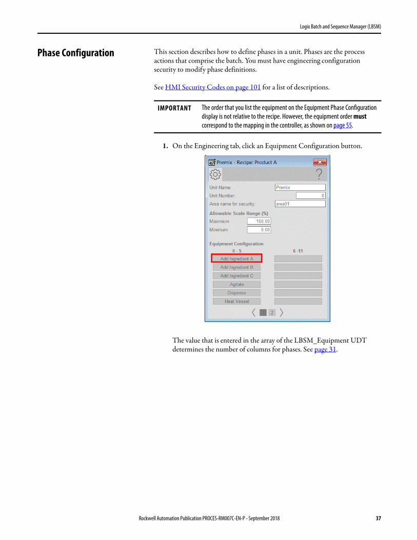
Phase Configuration This section describes how to define phases in a unit. Phases are the process actions that comprise the batch. You must have engineering configuration security to modify phase definitions.
See HMI Security Codes on page 101 for a list of descriptions.
1. On the Engineering tab, click an Equipment Configuration button.
The value that is entered in the array of the LBSM_Equipment UDT determines the number of columns for phases. See page 31.
IMPORTANT The order that you list the equipment on the Equipment Phase Configuration display is not relative to the recipe. However, the equipment order must correspond to the mapping in the controller, as shown on page 55.
Rockwell Automation Publication PROCES-RM007C-EN-P - September 2018 37

Logix Batch and Sequence Manager (LBSM)
The Phase Configuration display appears when an Equipment Configuration button is clicked.
2. Complete the Phase Configuration display.Table 6 - Phase Configuration Description
Topic Description
Equipment Name Type a name for the equipment. Phase columns without names are unused placeholders.
Phase Name Type a name for a phase. The name is often the same as the equipment name, but separate configurations have been provided if you want a different name for a phase.
Real ParametersThese are values in the formula, such as setpoints. Up to four Real parameters can be configured per phase. Each defined value is captured for reporting when the phase starts. You can configure these items for each parameter.
Phase Check to indicate that the parameter belongs to the phase. The parameters are exposed to the recipe author.IMPORTANT: Phase parameters can be changed from the Equipment Phase Configuration display or the Run Time Detail faceplate.
EM Click to indicate that the parameter belongs to the equipment module. The parameters are configurable attributes but not available for recipe configuration.IMPORTANT: Equipment module parameters can be modified only from the Run Time Detail faceplate.
Name Type a name for the parameter.
EU Type an engineering unit for the parameter.
38 Rockwell Automation Publication PROCES-RM007C-EN-P - September 2018

Logix Batch and Sequence Manager (LBSM)
LowHigh
Type a low value and a high value to set an operational range for the parameter. These values limit the entries when configuring a step or manually controlling the equipment.For example, you can set the high limit for a mixer speed of 30 if the mixer cannot exceed 30 rpm.
Scaled Check if the parameter value is to be scaled up or down when the scale factor for the batch is changed from 100%. Leave the box blank if the parameter value is to be the same when the batch is scaled.
Default Default values are constants that can be set when values are not expected to be used by an operator, maintenance personnel, sequence, or formulation.For example, you can change the temperature value to accommodate the physical equipment when commissioning. Large vats can require 10° while smaller vats can require 2°.IMPORTANT: A default value is not considered a phase or an equipment module parameter. Leave the Phase and EM boxes blank if you configure a default value.
If you use Real parameters, the equipment module code must be configured to interface with these LBSM parameters. Refer to Connect Equipment to Controller Logic on page 55 and Equipment Interface Codes on page 89.
Boolean ParametersThese are discrete values that the equipment phase sends to the equipment module, such as a mode selection. Each defined value is captured for reporting when the phase starts. Up to four Boolean parameters can be configured per phase. You can configure these items for each parameter.
Phase Check to indicate that the parameter belongs to the phase. The parameters are exposed to the
recipe author.IMPORTANT: Phase parameters can be changed from the Equipment Phase Configuration display or the Run Time Detail faceplate.
EM Click to indicate that the parameter belongs to the equipment module. These parameters are configurable attributes but are not available for recipe configuration.IMPORTANT: Equipment module parameters can be modified only from the Run Time Detail faceplate.
Name Type a name for the parameter.
Default Default is used for configurations that do not need to be accessed from the Run Time Detail faceplate. The configuration can default to either Off or On state. In this situation, the parameter is not considered a phase or equipment module parameter.
Off State The logic state descriptor for the Off state.
Default See Off State.
On State The logic state descriptor for the On state.
If Boolean parameters are used, the equipment module code must be configured to interface with these LBSM parameters. Refer to Connect Equipment to Controller Logic on page 55 and Equipment Interface Codes on page 89.
Table 6 - Phase Configuration Description
Topic Description
Rockwell Automation Publication PROCES-RM007C-EN-P - September 2018 39

Logix Batch and Sequence Manager (LBSM)
Configure a Master Recipe This section describes how to configure the procedural steps in a recipe. The current runtime sequence, which is the Control Recipe, manages the interaction of the phases to make product.
1. On the Operator tab, click the Manual Control tab.
Report ParametersThese are values that the equipment phase captures for reporting when the phase completes. For example, the actual amount of a material the equipment adds. You can configure these items for each parameter.
PhaseEM
Similar to Real and Boolean parameters, check to indicate that the parameter belongs to the phase, the equipment module, or both. IMPORTANT: Phase parameters appear on the Run Phase display that is accessed from the Run Time Detail faceplate.Equipment parameters appear on the Equipment Module display that is accessed from the equipment icon at the top of the Phase faceplate.
Name Type a name for the parameter.
EU Type an engineering unit for the parameter.
If required by the equipment phase, the equipment module code must be configured to the interface with these LBSM parameters. Refer to Connect Equipment to Controller Logic on page 55 and Equipment Interface Codes on page 89.
Table 6 - Phase Configuration Description
Topic Description
IMPORTANT Changes to a Control Recipe are not saved at the completion of a batch. You must use the Save As button to save the revised recipe as a Master Recipe. See page 53 for procedures.
40 Rockwell Automation Publication PROCES-RM007C-EN-P - September 2018
Logix Batch and Sequence Manager (LBSM)
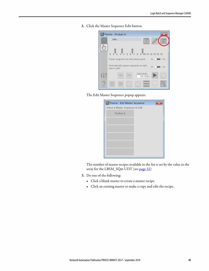
2. Click the Master Sequence Edit button.
The Edit Master Sequence popup appears.
The number of master recipes available in the list is set by the value in the array for the LBSM_SQm UDT (see page 32).
3. Do one of the following:• Click a blank master to create a master recipe.• Click an existing master to make a copy and edit the recipe.
Rockwell Automation Publication PROCES-RM007C-EN-P - September 2018 41

Logix Batch and Sequence Manager (LBSM)
The Recipe Configuration display appears.
The Product A Master Recipe from the LBSM demonstration, starting on page 69, is shown in the graphic.
4. To configure a step in a recipe, click the top of a numerical column – 0, 1, 2, 3, 4, and so on.
The Step Configuration display appears for the numbered step that you clicked. The example shows step 4.
42 Rockwell Automation Publication PROCES-RM007C-EN-P - September 2018
Logix Batch and Sequence Manager (LBSM)
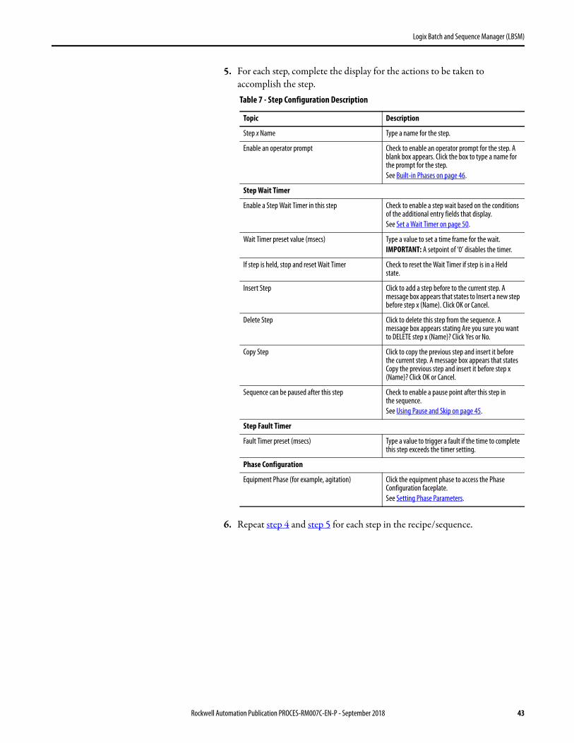
5. For each step, complete the display for the actions to be taken to accomplish the step.
6. Repeat step 4 and step 5 for each step in the recipe/sequence.
Table 7 - Step Configuration Description
Topic Description
Step x Name Type a name for the step.
Enable an operator prompt Check to enable an operator prompt for the step. A blank box appears. Click the box to type a name for the prompt for the step.See Built-in Phases on page 46.
Step Wait Timer
Enable a Step Wait Timer in this step Check to enable a step wait based on the conditions of the additional entry fields that display.See Set a Wait Timer on page 50.
Wait Timer preset value (msecs) Type a value to set a time frame for the wait.IMPORTANT: A setpoint of ‘0’ disables the timer.
If step is held, stop and reset Wait Timer Check to reset the Wait Timer if step is in a Held state.
Insert Step Click to add a step before to the current step. A message box appears that states to Insert a new step before step x (Name). Click OK or Cancel.
Delete Step Click to delete this step from the sequence. A message box appears stating Are you sure you want to DELETE step x (Name)? Click Yes or No.
Copy Step Click to copy the previous step and insert it before the current step. A message box appears that states Copy the previous step and insert it before step x (Name)? Click OK or Cancel.
Sequence can be paused after this step Check to enable a pause point after this step in
the sequence. See Using Pause and Skip on page 45.
Step Fault Timer
Fault Timer preset (msecs) Type a value to trigger a fault if the time to complete this step exceeds the timer setting.
Phase Configuration
Equipment Phase (for example, agitation) Click the equipment phase to access the Phase Configuration faceplate.See Setting Phase Parameters.
Rockwell Automation Publication PROCES-RM007C-EN-P - September 2018 43
Logix Batch and Sequence Manager (LBSM)
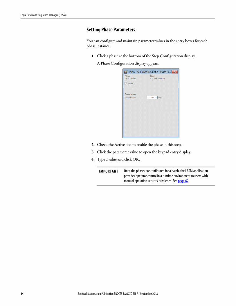
Setting Phase Parameters
You can configure and maintain parameter values in the entry boxes for each phase instance.
1. Click a phase at the bottom of the Step Configuration display.
A Phase Configuration display appears.
2. Check the Active box to enable the phase in this step.
3. Click the parameter value to open the keypad entry display.
4. Type a value and click OK.
IMPORTANT Once the phases are configured for a batch, the LBSM application provides operator control in a runtime environment to users with manual operation security privileges. See page 62.
44 Rockwell Automation Publication PROCES-RM007C-EN-P - September 2018
Logix Batch and Sequence Manager (LBSM)
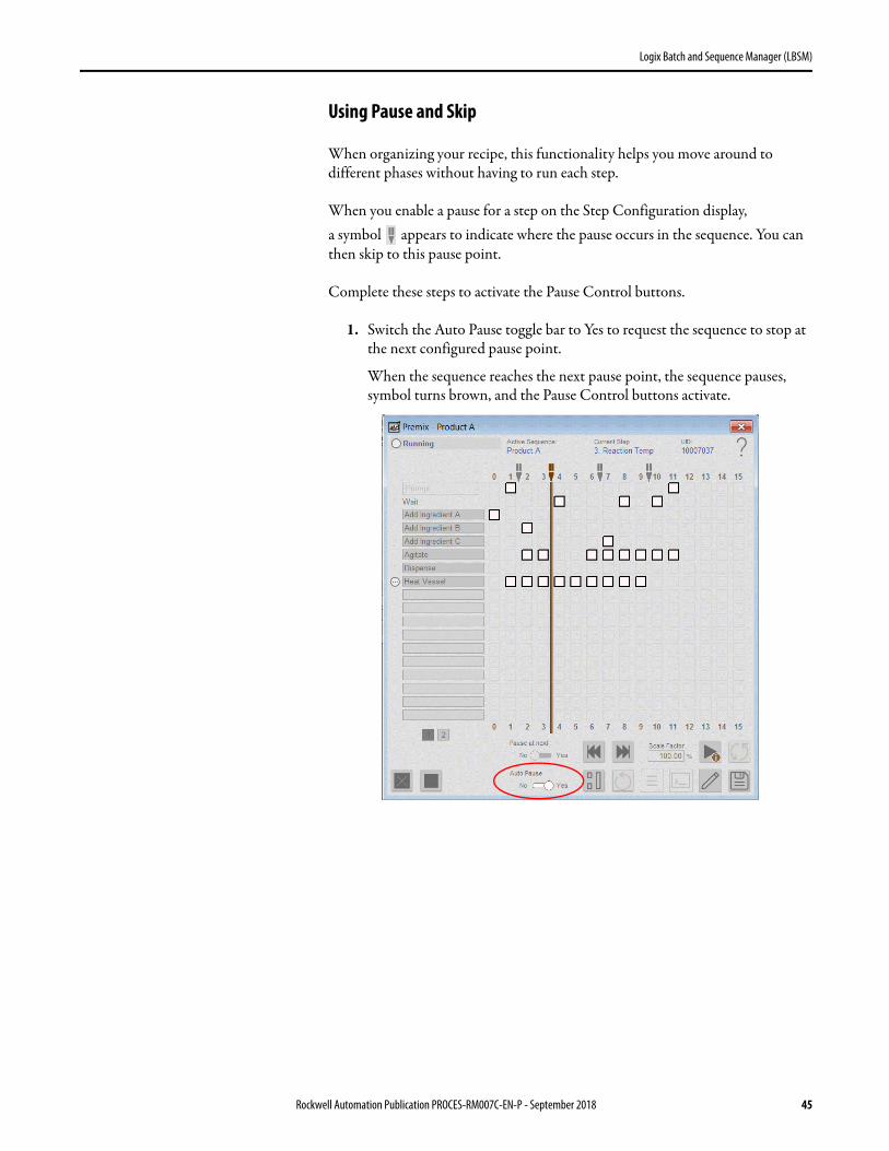
Using Pause and Skip
When organizing your recipe, this functionality helps you move around to different phases without having to run each step.
When you enable a pause for a step on the Step Configuration display, a symbol appears to indicate where the pause occurs in the sequence. You can then skip to this pause point.
Complete these steps to activate the Pause Control buttons.
1. Switch the Auto Pause toggle bar to Yes to request the sequence to stop at the next configured pause point.
When the sequence reaches the next pause point, the sequence pauses, symbol turns brown, and the Pause Control buttons activate.
Rockwell Automation Publication PROCES-RM007C-EN-P - September 2018 45
Logix Batch and Sequence Manager (LBSM)
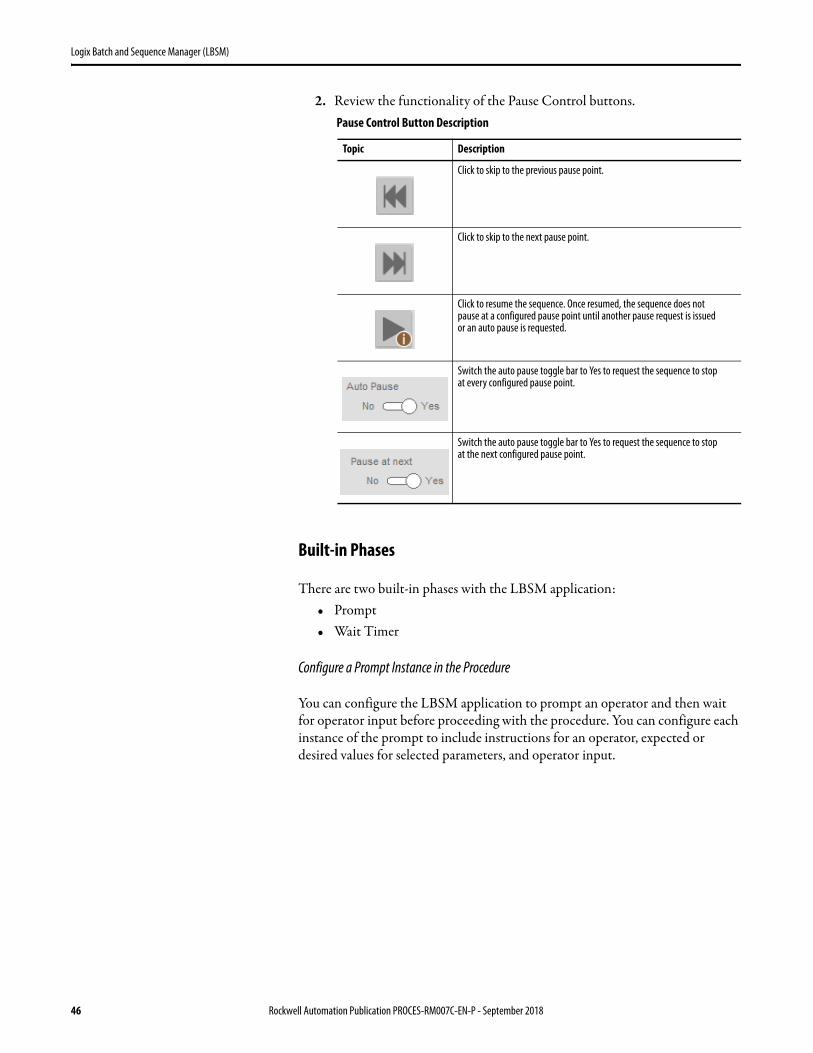
2. Review the functionality of the Pause Control buttons.
Built-in Phases
There are two built-in phases with the LBSM application:• Prompt• Wait Timer
Configure a Prompt Instance in the Procedure
You can configure the LBSM application to prompt an operator and then wait for operator input before proceeding with the procedure. You can configure each instance of the prompt to include instructions for an operator, expected or desired values for selected parameters, and operator input.
Pause Control Button Description
Topic Description
Click to skip to the previous pause point.
Click to skip to the next pause point.
Click to resume the sequence. Once resumed, the sequence does not pause at a configured pause point until another pause request is issued
or an auto pause is requested.
Switch the auto pause toggle bar to Yes to request the sequence to stop
at every configured pause point.
Switch the auto pause toggle bar to Yes to request the sequence to stop
at the next configured pause point.
46 Rockwell Automation Publication PROCES-RM007C-EN-P - September 2018
Logix Batch and Sequence Manager (LBSM)
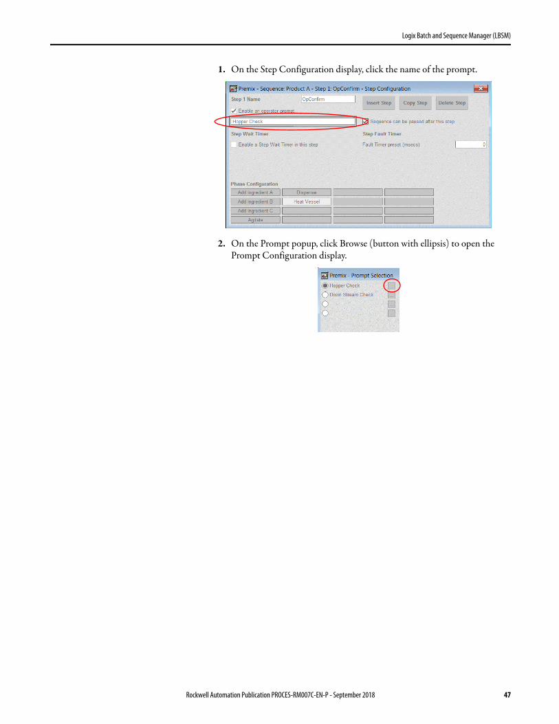
1. On the Step Configuration display, click the name of the prompt.
2. On the Prompt popup, click Browse (button with ellipsis) to open the Prompt Configuration display.
Rockwell Automation Publication PROCES-RM007C-EN-P - September 2018 47
Logix Batch and Sequence Manager (LBSM)
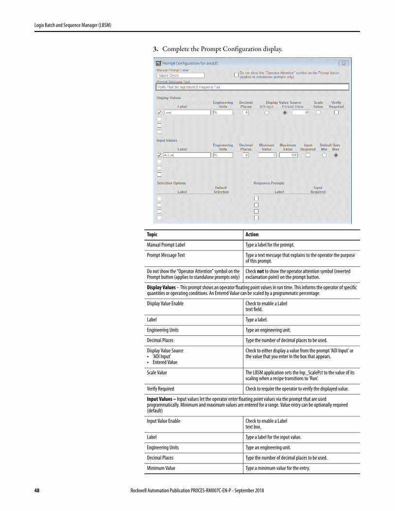
3. Complete the Prompt Configuration display.
Topic Action
Manual Prompt Label Type a label for the prompt.
Prompt Message Text Type a text message that explains to the operator the purpose of this prompt.
Do not show the “Operator Attention” symbol on the Prompt button (applies to standalone prompts only)
Check not to show the operator attention symbol (inverted exclamation point) on the prompt button.
Display Values – This prompt shows an operator floating point values in run time. This informs the operator of specific quantities or operating conditions. An Entered Value can be scaled by a programmatic percentage.
Display Value Enable Check to enable a Label text field.
Label Type a label.
Engineering Units Type an engineering unit.
Decimal Places Type the number of decimal places to be used.
Display Value Source• 'AOI Input'• Entered Value
Check to either display a value from the prompt 'AOI Input' or the value that you enter in the box that appears.
Scale Value The LBSM application sets the Inp_ScalePct to the value of its scaling when a recipe transitions to ‘Run’.
Verify Required Check to require the operator to verify the displayed value.
Input Values – Input values let the operator enter floating point values via the prompt that are used programmatically. Minimum and maximum values are entered for a range. Value entry can be optionally required (default)
Input Value Enable Check to enable a Label text box.
Label Type a label for the input value.
Engineering Units Type an engineering unit.
Decimal Places Type the number of decimal places to be used.
Minimum Value Type a minimum value for the entry.
48 Rockwell Automation Publication PROCES-RM007C-EN-P - September 2018
Logix Batch and Sequence Manager (LBSM)
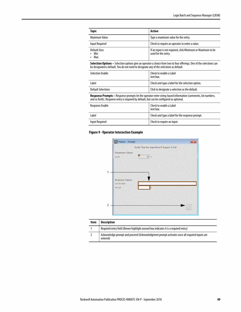
Figure 9 - Operator Interaction Example
Maximum Value Type a maximum value for the entry.
Input Required Check to require an operator to enter a value.
Default Uses• Min• Max
If an input is not required, click Minimum or Maximum to be used for the entry.
Selection Options – Selection options give an operator a choice from two to four offerings. One of the selections can be designated a default. You do not need to designate any of the selections as default.
Selection Enable Check to enable a Label text box.
Label Check and type a label for the selection option.
Default Selections Click to designate a selection as the default.
Response Prompts – Response prompts let the operator enter string-based information (comments, lot numbers, and so forth). Response entry is required by default, but can be configured as optional.
Response Enable Check to enable a Label text box.
Label Check and type a label for the response prompt.
Input Required Check to require an input.
Item Description
1 Required entry field (Brown highlight around box indicates it is a required entry)
2 Acknowledge prompt and proceed (Acknowledgment prompt activates once all required inputs are entered)
Topic Action
1
2
Rockwell Automation Publication PROCES-RM007C-EN-P - September 2018 49
Logix Batch and Sequence Manager (LBSM)
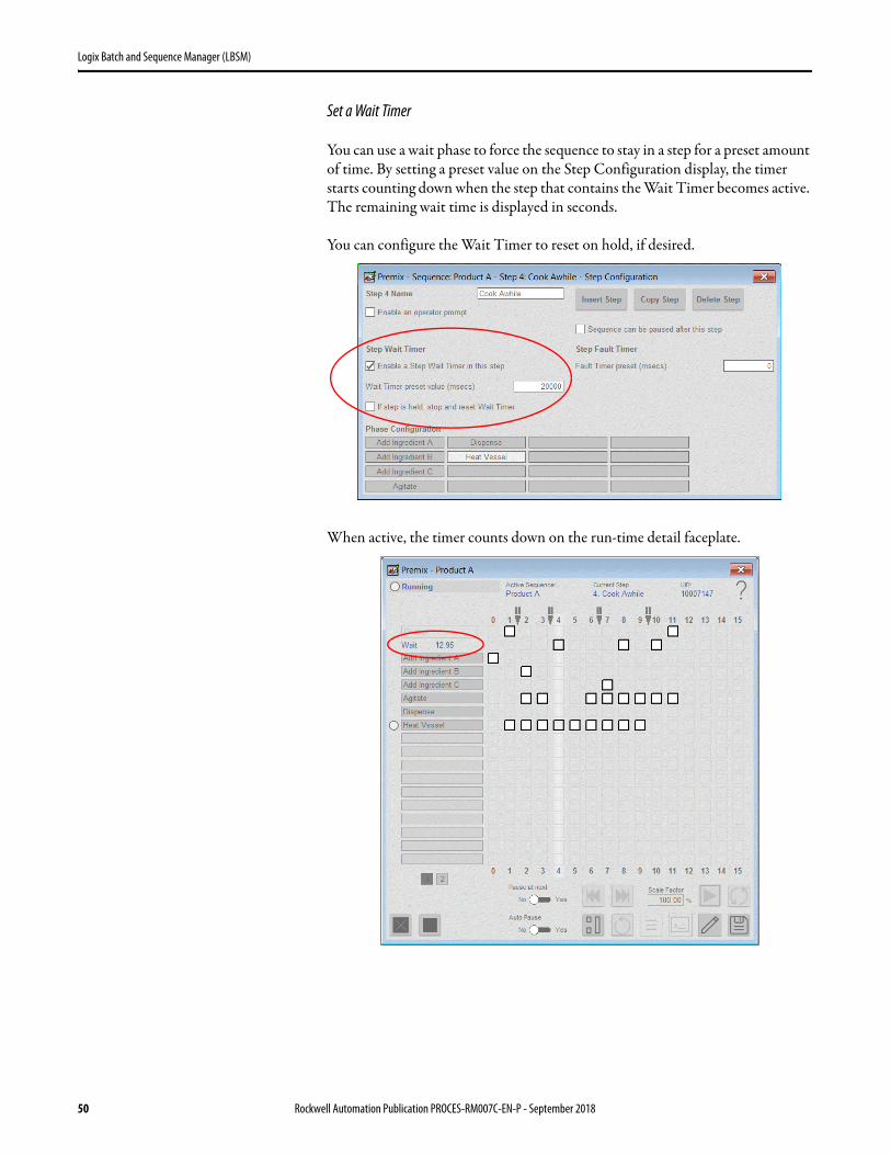
Set a Wait Timer
You can use a wait phase to force the sequence to stay in a step for a preset amount of time. By setting a preset value on the Step Configuration display, the timer starts counting down when the step that contains the Wait Timer becomes active. The remaining wait time is displayed in seconds.
You can configure the Wait Timer to reset on hold, if desired.
When active, the timer counts down on the run-time detail faceplate.
50 Rockwell Automation Publication PROCES-RM007C-EN-P - September 2018
Logix Batch and Sequence Manager (LBSM)
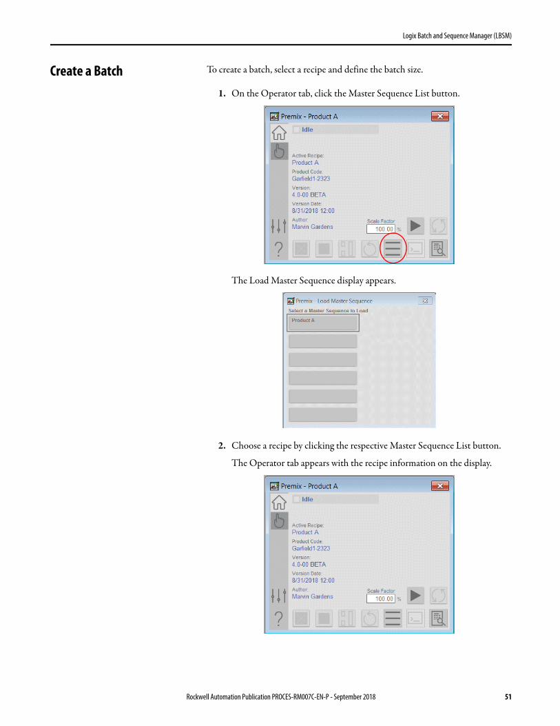
Create a Batch To create a batch, select a recipe and define the batch size.
1. On the Operator tab, click the Master Sequence List button.
The Load Master Sequence display appears.
2. Choose a recipe by clicking the respective Master Sequence List button.
The Operator tab appears with the recipe information on the display.
Rockwell Automation Publication PROCES-RM007C-EN-P - September 2018 51

Logix Batch and Sequence Manager (LBSM)
3. In the Scale Factor entry box, type a value.
Default value is 100%.
4. Click the Start Command button to begin operating the batch.
See the demonstration on page 69.
52 Rockwell Automation Publication PROCES-RM007C-EN-P - September 2018

Logix Batch and Sequence Manager (LBSM)
Save Master Recipe Changes applied to a Control Recipe can be saved to a Master Recipe if you want to use the same data for other batches. Complete these steps.
1. On the Run Time Detail faceplate, click the Save As button.
The Save Sequence As window appears.
Rockwell Automation Publication PROCES-RM007C-EN-P - September 2018 53

Logix Batch and Sequence Manager (LBSM)
2. Click a button to save the current recipe as a new Master recipe. If you click an empty button, the recipe saves to that slot. If you click the currently loaded product slot a warning message displays.
3. To overwrite the current recipe, type a name for the new master recipe and press the Yes button.
IMPORTANT Make sure to upload your changes in the Logix Designer application after modifying your Master Recipe.
54 Rockwell Automation Publication PROCES-RM007C-EN-P - September 2018

Logix Batch and Sequence Manager (LBSM)
Connect Equipment to Controller Logic
The LBSM application interfaces to your equipment through a tag named _Equipment. This tag is an array that is composed of two data types:
• EM_Composite (see list of interface codes on page 89)• PIDefinition
These data types store the configuration for your equipment phase instances. The objects on the Equipment Configuration display align with the members of this array. For example, the equipment phases for the first unit (unit 0) align with the _Equipment array as illustrated.
Expanding _Equipment[3] reveals how the _Equipment array aligns with several other objects on the Equipment Configuration display for the phase instance of the first unit instance [0].
The LBSM application supports two equipment interfaces to your selected controller:
• PhaseManager – see page 56• Bit Interface – see page 58
Depending on your equipment need, choose the appropriate interface. You can use either one or both in any application.
Rockwell Automation Publication PROCES-RM007C-EN-P - September 2018 55
Logix Batch and Sequence Manager (LBSM)
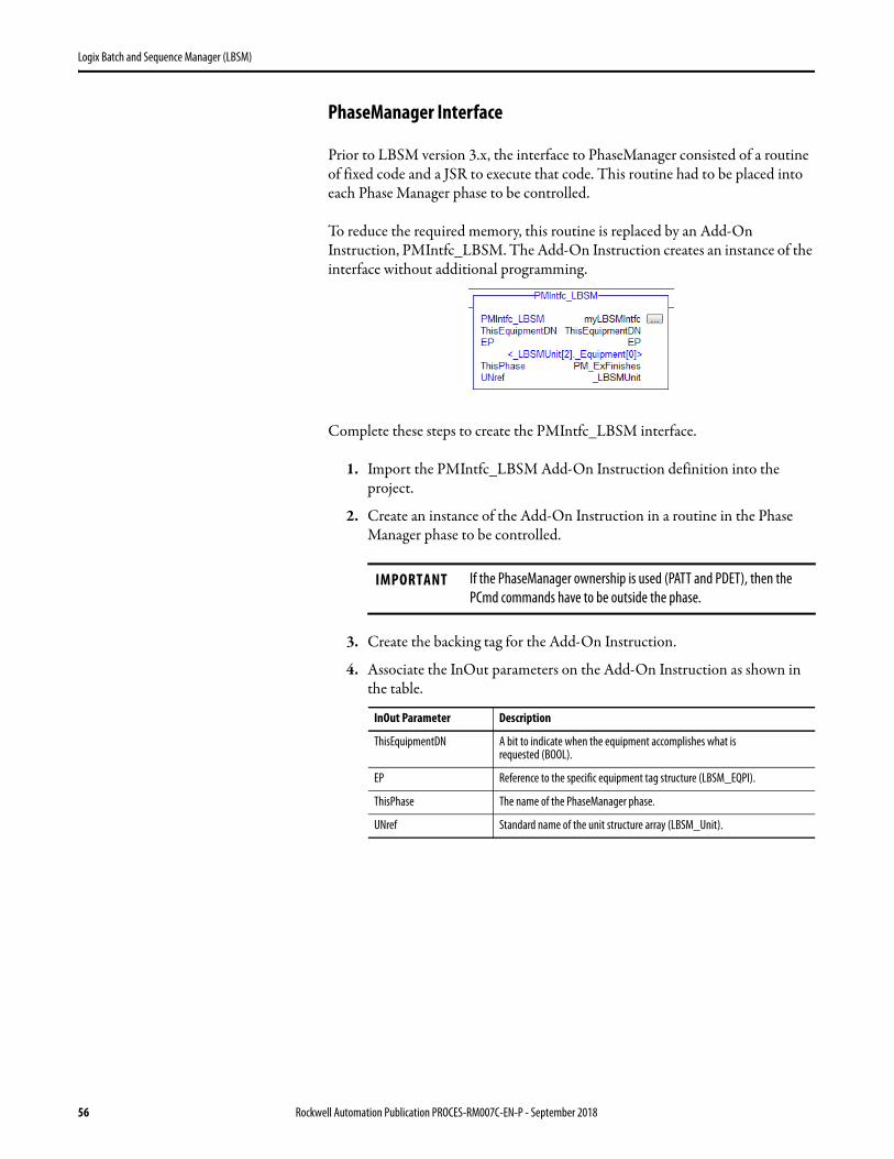
PhaseManager Interface
Prior to LBSM version 3.x, the interface to PhaseManager consisted of a routine of fixed code and a JSR to execute that code. This routine had to be placed into each Phase Manager phase to be controlled.
To reduce the required memory, this routine is replaced by an Add-On Instruction, PMIntfc_LBSM. The Add-On Instruction creates an instance of the interface without additional programming.
Complete these steps to create the PMIntfc_LBSM interface.
1. Import the PMIntfc_LBSM Add-On Instruction definition into the project.
2. Create an instance of the Add-On Instruction in a routine in the Phase Manager phase to be controlled.
3. Create the backing tag for the Add-On Instruction.
4. Associate the InOut parameters on the Add-On Instruction as shown in the table.
IMPORTANT If the PhaseManager ownership is used (PATT and PDET), then the PCmd commands have to be outside the phase.
InOut Parameter Description
ThisEquipmentDN A bit to indicate when the equipment accomplishes what is requested (BOOL).
EP Reference to the specific equipment tag structure (LBSM_EQPI).
ThisPhase The name of the PhaseManager phase.
UNref Standard name of the unit structure array (LBSM_Unit).
56 Rockwell Automation Publication PROCES-RM007C-EN-P - September 2018

Logix Batch and Sequence Manager (LBSM)
5. Program the outputs of the PMIntfc_LBSM instruction to command the PhaseManager phase.
As stated in the Important for step 2, the PCMD commands can be in the PhaseManager phase program only if the ‘Acquire’ (PATT and PDET) and ownership is not used.
Rockwell Automation Publication PROCES-RM007C-EN-P - September 2018 57
Logix Batch and Sequence Manager (LBSM)
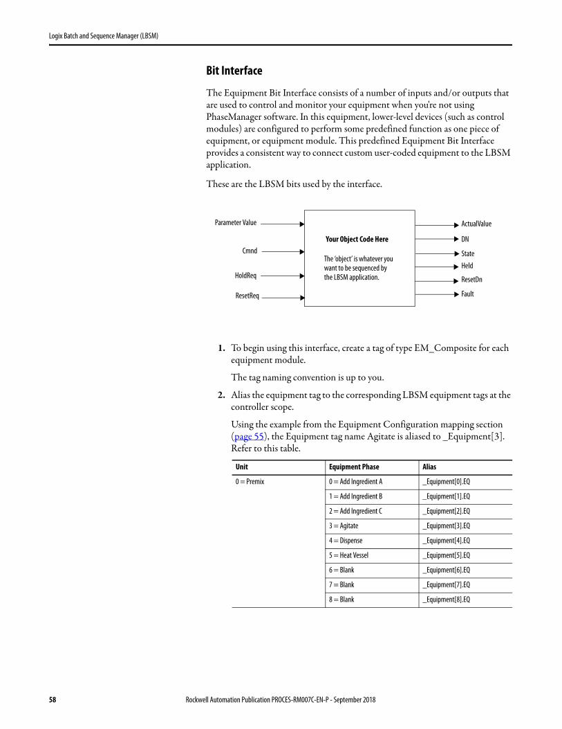
Bit Interface
The Equipment Bit Interface consists of a number of inputs and/or outputs that are used to control and monitor your equipment when you're not using PhaseManager software. In this equipment, lower-level devices (such as control modules) are configured to perform some predefined function as one piece of equipment, or equipment module. This predefined Equipment Bit Interface provides a consistent way to connect custom user-coded equipment to the LBSM application.
These are the LBSM bits used by the interface.
1. To begin using this interface, create a tag of type EM_Composite for each equipment module.
The tag naming convention is up to you.
2. Alias the equipment tag to the corresponding LBSM equipment tags at the controller scope.
Using the example from the Equipment Configuration mapping section (page 55), the Equipment tag name Agitate is aliased to _Equipment[3]. Refer to this table.
Unit Equipment Phase Alias
0 = Premix 0 = Add Ingredient A _Equipment[0].EQ
1 = Add Ingredient B _Equipment[1].EQ
2 = Add Ingredient C _Equipment[2].EQ
3 = Agitate _Equipment[3].EQ
4 = Dispense _Equipment[4].EQ
5 = Heat Vessel _Equipment[5].EQ
6 = Blank _Equipment[6].EQ
7 = Blank _Equipment[7].EQ
8 = Blank _Equipment[8].EQ
Your Object Code Here
Parameter Value
Cmnd
HoldReq
ResetReq
ActualValue
DN
StateHeld
ResetDn
Fault
The ‘object’ is whatever you want to be sequenced by the LBSM application.
58 Rockwell Automation Publication PROCES-RM007C-EN-P - September 2018

Logix Batch and Sequence Manager (LBSM)
3. Use the equipment tags created in step 1 to program each equipment module interface with these bits.
4. Add an instance of the EM_LBSM Add-On Instruction to each equipment module.
The EM_LBSM Add-On Instruction manages the equipment module modes and handshakes to the rest of the system. You must use this in each equipment module that you create.
Member Data Type Description
Cmnd BOOL Boolean inputs that command
the object code to perform its primary function.
ParameterValues ParameterValues Inputs to the object code that can be modified from the HMI. For example, setpoints. You can use
a maximum of four Real and four Boolean parameters.
HoldReq BOOL Boolean input that requests the object code to perform its Hold function. This could be to go to a known state or stay where it is (do nothing).
ResetReq BOOL Boolean input that requests the object code to reset; put the EM into a known initial state, ready to
run again.
State BOOL Boolean output that indicates that the object code is Off (0) or On (1).
DN BOOL Boolean output that indicates that the object code has achieved its final state. User program must always set this tag at some point in the operation of the EM.See Use the DN and State Bits on page 60.
Actual ActualValues Outputs saved for reporting.
ResetDN BOOL Boolean output that indicates that the object code has been reset caused by the setting of the ResetReq input.
Held BOOL Boolean output that indicates the object code is in a state caused by the setting of the HoldReq input.
Fault BOOL Indicates an object code fault. Could be the OR'ed composite of all code component faults.
Health BOOL Indicates bad object code health. Could be the OR'ed composite of all code component health bits (like CM IO health bits).
IMPORTANT Refer to Appendix A for details of the EM_Composite data type.Refer to Appendix B for several example applications.
Rockwell Automation Publication PROCES-RM007C-EN-P - September 2018 59

Logix Batch and Sequence Manager (LBSM)
Use the DN and State Bits
The relationship between the DN and State bits is critical for the appropriate behavior of procedural handling of equipment entities. There are two distinct behaviors that can occur:
• Equipment completes (finish and be released)• Equipment qualifies step and continues activity• Completion – If DN = 1 and State = 0. This combination of bits instructs
the engine that the equipment has finished what was requested (EM.DN=1) and is in a low state or de-energized (EM.State=0).
Example: Ingredient Addition
The equipment is to add a specified amount of an ingredient.
EM.Cmnd=1 tells the equipment to perform its function.
EM.State=1 to indicate that it is adding material.
EM.State=0 to indicate that it is no longer adding material.
EM.DN=1 to indicate that it is done (has added the requested amount and turned off ).
• Finish, keep running – If DN = 1 and State = 1. The equipment accomplishes what has been requested but remains running.
Example: Simple Agitation
The equipment is to maintain an agitator at a specified speed.
EM.Cmnd=1 tells the equipment to perform its function.
EM.State=1 to indicate that it is running.
EM.DN=1 to indicate that it is done (has attained the desired speed).
46292
EM.Cmnd
EM.State
EM.DN
46293
EM.Cmnd
EM.State
EM.DN
60 Rockwell Automation Publication PROCES-RM007C-EN-P - September 2018
Logix Batch and Sequence Manager (LBSM)
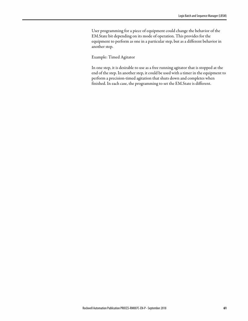
User programming for a piece of equipment could change the behavior of the EM.State bit depending on its mode of operation. This provides for the equipment to perform as one in a particular step, but as a different behavior in another step.
Example: Timed Agitator
In one step, it is desirable to use as a free running agitator that is stopped at the end of the step. In another step, it could be used with a timer in the equipment to perform a precision-timed agitation that shuts down and completes when finished. In each case, the programming to set the EM.State is different.
Rockwell Automation Publication PROCES-RM007C-EN-P - September 2018 61

Logix Batch and Sequence Manager (LBSM)
Operator Phase Control Users with the proper security can take control of a phase in a runtime environment. Complete these steps.
1. On the Run Time Detail faceplate, click an equipment box to access the Phase Control faceplate.
2. Click the Acquire Equipment button to let an authorized user take ownership of the phase.
62 Rockwell Automation Publication PROCES-RM007C-EN-P - September 2018
Logix Batch and Sequence Manager (LBSM)
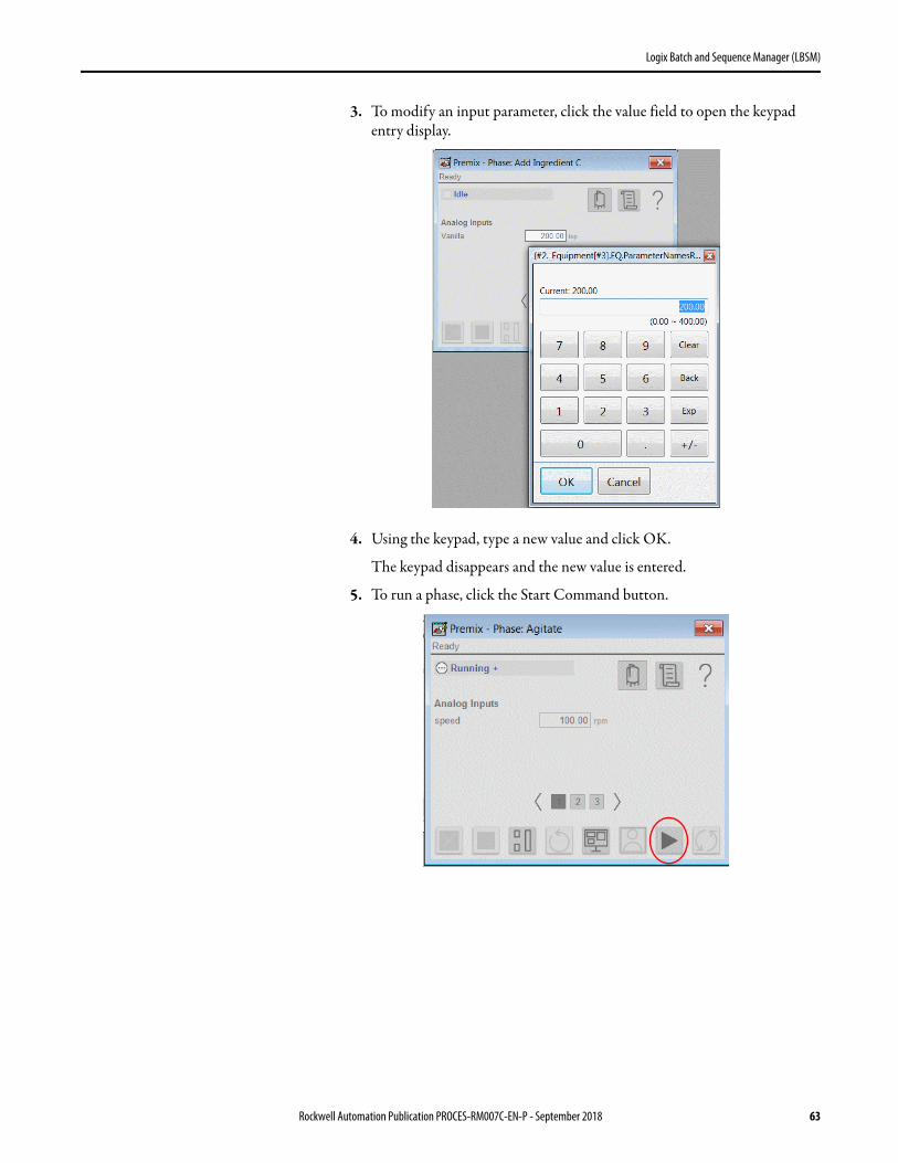
3. To modify an input parameter, click the value field to open the keypad entry display.
4. Using the keypad, type a new value and click OK.
The keypad disappears and the new value is entered.
5. To run a phase, click the Start Command button.
Rockwell Automation Publication PROCES-RM007C-EN-P - September 2018 63
Logix Batch and Sequence Manager (LBSM)
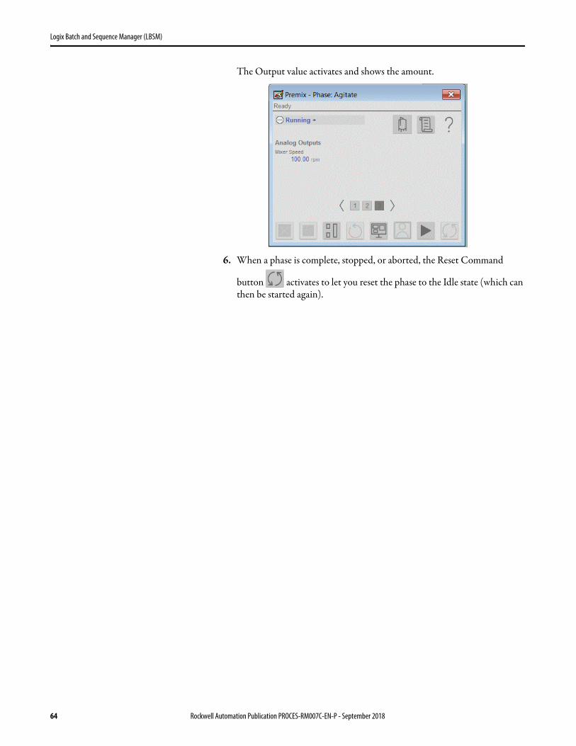
The Output value activates and shows the amount.
6. When a phase is complete, stopped, or aborted, the Reset Command
button activates to let you reset the phase to the Idle state (which can then be started again).
64 Rockwell Automation Publication PROCES-RM007C-EN-P - September 2018
Logix Batch and Sequence Manager (LBSM)
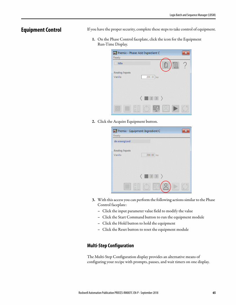
Equipment Control If you have the proper security, complete these steps to take control of equipment.
1. On the Phase Control faceplate, click the icon for the Equipment Run-Time Display.
2. Click the Acquire Equipment button.
3. With this access you can perform the following actions similar to the Phase Control faceplate:– Click the input parameter value field to modify the value– Click the Start Command button to run the equipment module– Click the Hold button to hold the equipment– Click the Reset button to reset the equipment module
Multi-Step Configuration
The Multi-Step Configuration display provides an alternative means of configuring your recipe with prompts, pauses, and wait timers on one display.
Rockwell Automation Publication PROCES-RM007C-EN-P - September 2018 65
Logix Batch and Sequence Manager (LBSM)
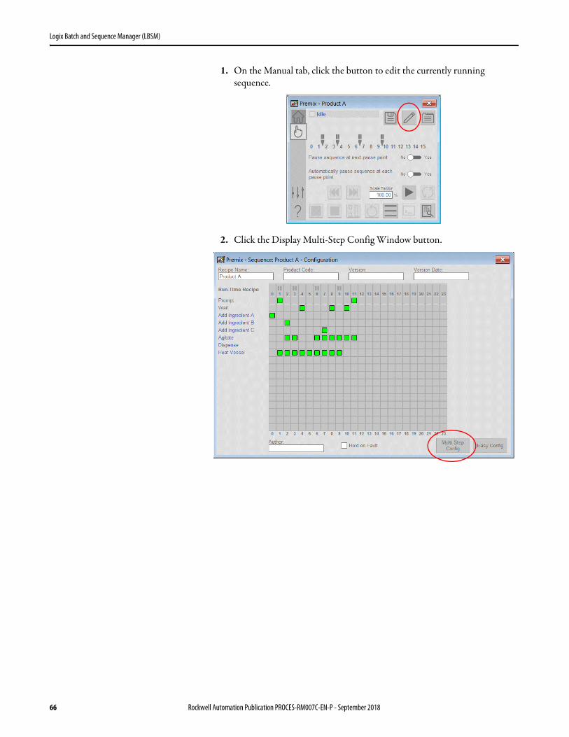
1. On the Manual tab, click the button to edit the currently running sequence.
2. Click the Display Multi-Step Config Window button.
66 Rockwell Automation Publication PROCES-RM007C-EN-P - September 2018

Logix Batch and Sequence Manager (LBSM)
3. Complete the Multi-Step Configuration display.
Table 8 - Multi-Step Configuration Description
Topic Description
Step Name Type a name for the step.
Allow Pause Check to let the sequence pause after this step.
Oper Prompt Check to use a prompt message for an operator to take action. A Browse (…) button appears to provide access to a Manual Prompt faceplate to configure the specific prompt message.
Step Wait Time Check and type a value for the step wait time, if applicable for the step.
Step Fault Time Type a value (in milliseconds) for the Step Fault Time. If the time to complete this step exceeds the timer setting, a step timeout is triggered.
Rockwell Automation Publication PROCES-RM007C-EN-P - September 2018 67
Logix Batch and Sequence Manager (LBSM)
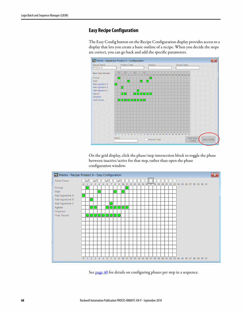
Easy Recipe Configuration
The Easy Config button on the Recipe Configuration display provides access to a display that lets you create a basic outline of a recipe. When you decide the steps are correct, you can go back and add the specific parameters.
On the grid display, click the phase/step intersection block to toggle the phase between inactive/active for that step, rather than open the phase
configuration window.
See page 40 for details on configuring phases per step in a sequence.
68 Rockwell Automation Publication PROCES-RM007C-EN-P - September 2018

Logix Batch and Sequence Manager (LBSM)
Start/Run Batch Demonstration
This section steps through a demonstration of LBSM functionality by using the provided FactoryTalk View HMI components. The demonstration assumes that the installation and configuration steps have been completed, and that a batch has been created. We cover these preliminary steps later in the manual.
The red circle in the illustration indicates that our demonstration, or running a batch in general, occurs after the configuration of several application benchmarks. After the demonstration, we’ll walk you through each section (denoted by page number) with the configuration activities that comprise the master recipe.
In the LBSM demonstration, we use recipe ‘Product A’ to add and mix three ingredients to tank ‘Premix 1’, and then transfer the resulting product from the tank. LBSM lets you break the capabilities of the process into independent process actions, which can include operator interaction via prompts.
Figure 10 - LBSM Unit Example
Install ComponentsSee page 37
Demonstration Starting PointSee page 69
Complete each section as listed to configure your batch system.
Equipment InterfaceSee page 56 and page 89
Start/Run
Batch
CreateBatch
See page 51
Configure LBSM
See page 30
ConfigureUnits
See page 37
ConfigurePhases
See page 37
ConfigureMaster RecipeSee page 40
See page 55
Operator Prompts
Ingredients
1 23
Agitator
Transfer Out
Rockwell Automation Publication PROCES-RM007C-EN-P - September 2018 69
Logix Batch and Sequence Manager (LBSM)
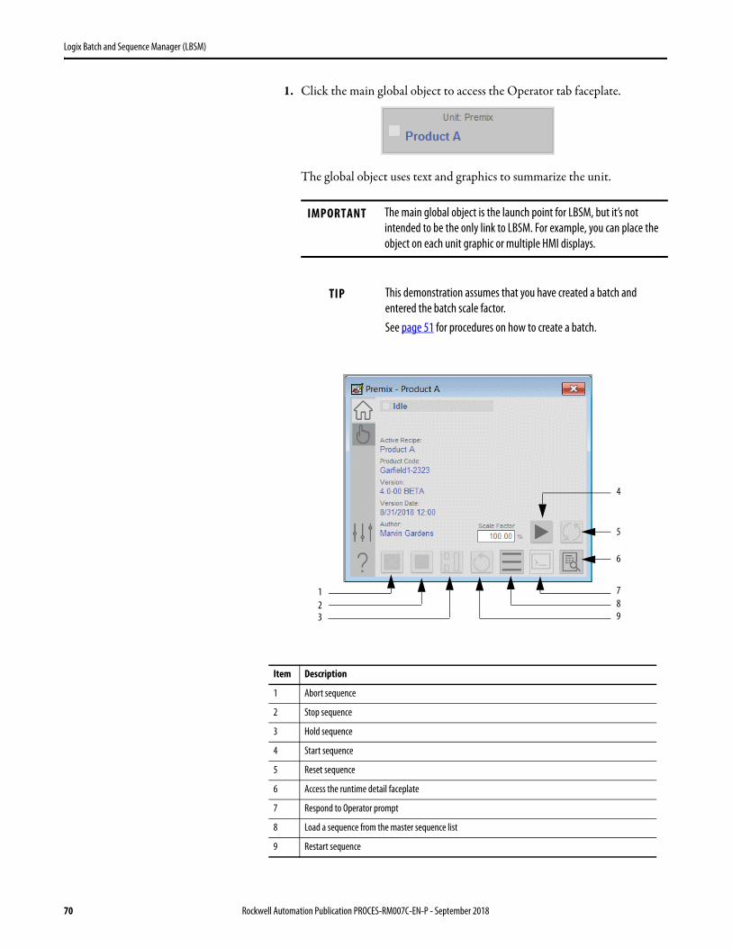
1. Click the main global object to access the Operator tab faceplate.
The global object uses text and graphics to summarize the unit.
IMPORTANT The main global object is the launch point for LBSM, but it’s not intended to be the only link to LBSM. For example, you can place the object on each unit graphic or multiple HMI displays.
TIP This demonstration assumes that you have created a batch and entered the batch scale factor.See page 51 for procedures on how to create a batch.
Item Description
1 Abort sequence
2 Stop sequence
3 Hold sequence
4 Start sequence
5 Reset sequence
6 Access the runtime detail faceplate
7 Respond to Operator prompt
8 Load a sequence from the master sequence list
9 Restart sequence
123
4
5
6
789
70 Rockwell Automation Publication PROCES-RM007C-EN-P - September 2018

Logix Batch and Sequence Manager (LBSM)
The same buttons on the Operator tab are also available on the Run Time Detail faceplate. The Run Time Detail faceplate visually arranges the progress of the procedural steps.
2. Access the Run Time Detail faceplate.
3. On the Run Time Detail faceplate, click the Start button.
You can start a batch only when it’s in the Idle state.
The Start command button, when clicked, transitions the batch to the Running state. Each time a batch starts, the batch or sequence unique ID is incremented.
1
2
3
4
Item Description
1 Sequence steps
2 Equipment phases
3 Pause point
4 A white box indicates that this phase is configured in this step.
Rockwell Automation Publication PROCES-RM007C-EN-P - September 2018 71
Logix Batch and Sequence Manager (LBSM)
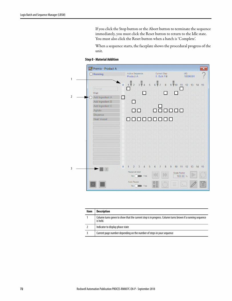
If you click the Stop button or the Abort button to terminate the sequence immediately, you must click the Reset button to return to the Idle state. You must also click the Reset button when a batch is ‘Complete’.
When a sequence starts, the faceplate shows the procedural progress of the unit.
Step 0 - Material Addition
1
2
3
Item Description
1 Column turns green to show that the current step is in progress. Column turns brown if a running sequence is held.
2 Indicator to display phase state
3 Current page number depending on the number of steps in your sequence
72 Rockwell Automation Publication PROCES-RM007C-EN-P - September 2018

Logix Batch and Sequence Manager (LBSM)
Step 1 - Heat Vessel
1
2
3
4
Item Description
1 Indicator to signify that operator interaction is required
2 Phase State
3 Black dot in the white box indicates that the phase has been completed
4 Indicator to signify that operator interaction is required
Rockwell Automation Publication PROCES-RM007C-EN-P - September 2018 73
Logix Batch and Sequence Manager (LBSM)
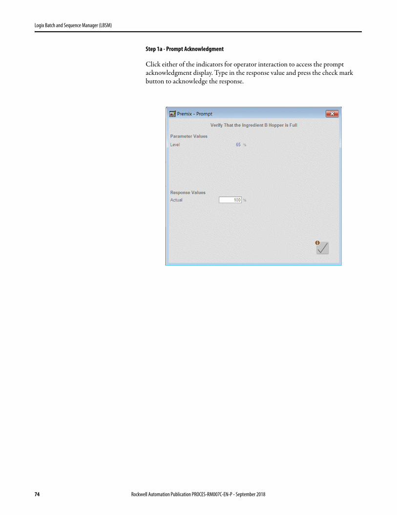
Step 1a - Prompt Acknowledgment
Click either of the indicators for operator interaction to access the prompt acknowledgment display. Type in the response value and press the check mark button to acknowledge the response.
74 Rockwell Automation Publication PROCES-RM007C-EN-P - September 2018
Logix Batch and Sequence Manager (LBSM)
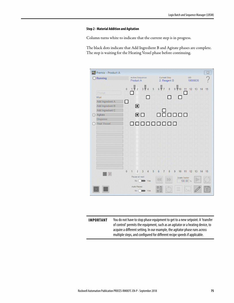
Step 2 - Material Addition and Agitation
Column turns white to indicate that the current step is in progress.
The black dots indicate that Add Ingredient B and Agitate phases are complete. The step is waiting for the Heating Vessel phase before continuing.
IMPORTANT You do not have to stop phase equipment to get to a new setpoint. A ‘transfer of control’ permits the equipment, such as an agitator or a heating device, to acquire a different setting. In our example, the agitator phase runs across multiple steps, and configured for different recipe speeds if applicable.
Rockwell Automation Publication PROCES-RM007C-EN-P - September 2018 75
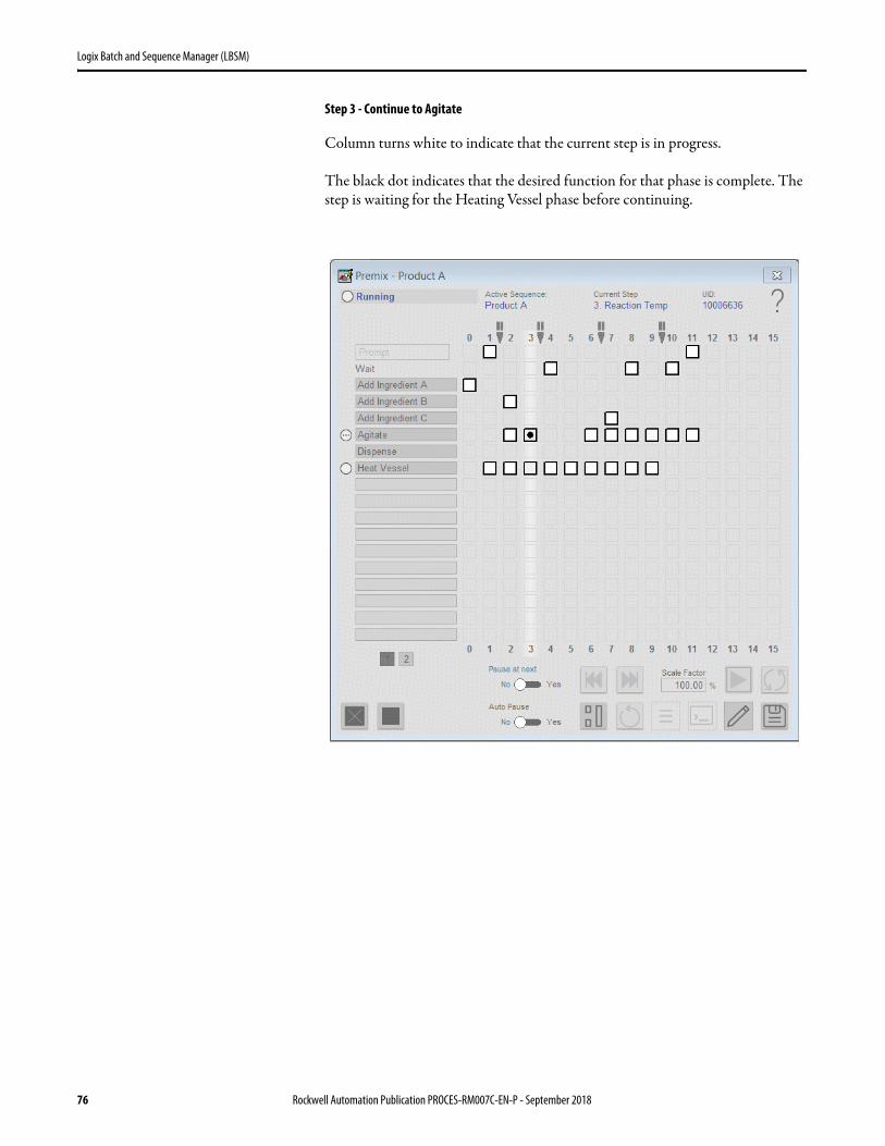
Logix Batch and Sequence Manager (LBSM)
Step 3 - Continue to Agitate
Column turns white to indicate that the current step is in progress.
The black dot indicates that the desired function for that phase is complete. The step is waiting for the Heating Vessel phase before continuing.
76 Rockwell Automation Publication PROCES-RM007C-EN-P - September 2018

Logix Batch and Sequence Manager (LBSM)
Step 4 - Heat Vessel, Wait Timer
Column turns white to indicate that the current step is in progress.
The wait timer starts timing when the step becomes active. The timer counts down from the preset value. The remaining wait time is displayed in seconds.
The black dot indicates that the desired function for that phase is complete.
Rockwell Automation Publication PROCES-RM007C-EN-P - September 2018 77

Logix Batch and Sequence Manager (LBSM)
Step 5 - Continue to Heat Vessel, Hold Functionality
Column turns white to indicate that the current step is in progress.
Column turns brown when a running sequence is Held. All active phases are commanded to their respective hold states. The sequence can then be restarted, stopped, or aborted.
78 Rockwell Automation Publication PROCES-RM007C-EN-P - September 2018

Logix Batch and Sequence Manager (LBSM)
Step 6 - Agitate, Heat Vessel
Column turns white to indicate that the current step is in progress.
The black dot indicates that the desired function for that phase is complete.
Rockwell Automation Publication PROCES-RM007C-EN-P - September 2018 79
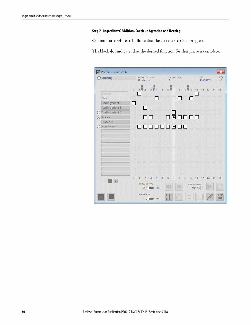
Logix Batch and Sequence Manager (LBSM)
Step 7 - Ingredient C Addition, Continue Agitation and Heating
Column turns white to indicate that the current step is in progress.
The black dot indicates that the desired function for that phase is complete.
80 Rockwell Automation Publication PROCES-RM007C-EN-P - September 2018
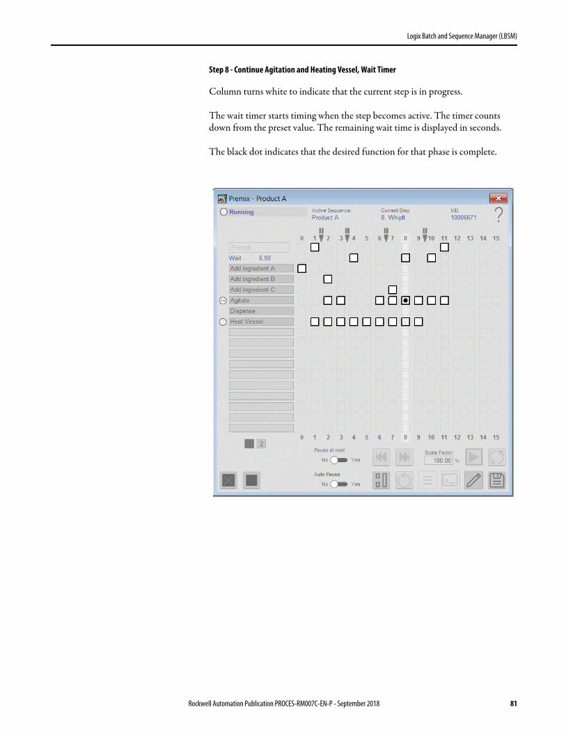
Logix Batch and Sequence Manager (LBSM)
Step 8 - Continue Agitation and Heating Vessel, Wait Timer
Column turns white to indicate that the current step is in progress.
The wait timer starts timing when the step becomes active. The timer counts down from the preset value. The remaining wait time is displayed in seconds.
The black dot indicates that the desired function for that phase is complete.
Rockwell Automation Publication PROCES-RM007C-EN-P - September 2018 81
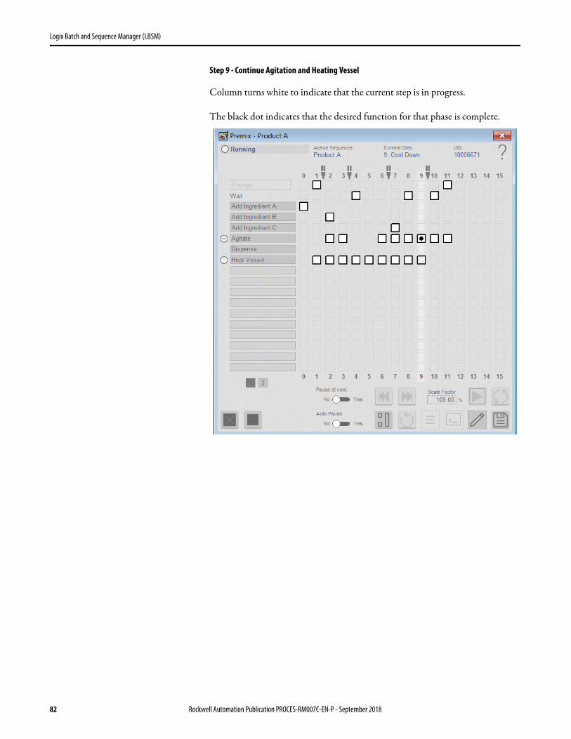
Logix Batch and Sequence Manager (LBSM)
Step 9 - Continue Agitation and Heating Vessel
Column turns white to indicate that the current step is in progress.
The black dot indicates that the desired function for that phase is complete.
82 Rockwell Automation Publication PROCES-RM007C-EN-P - September 2018
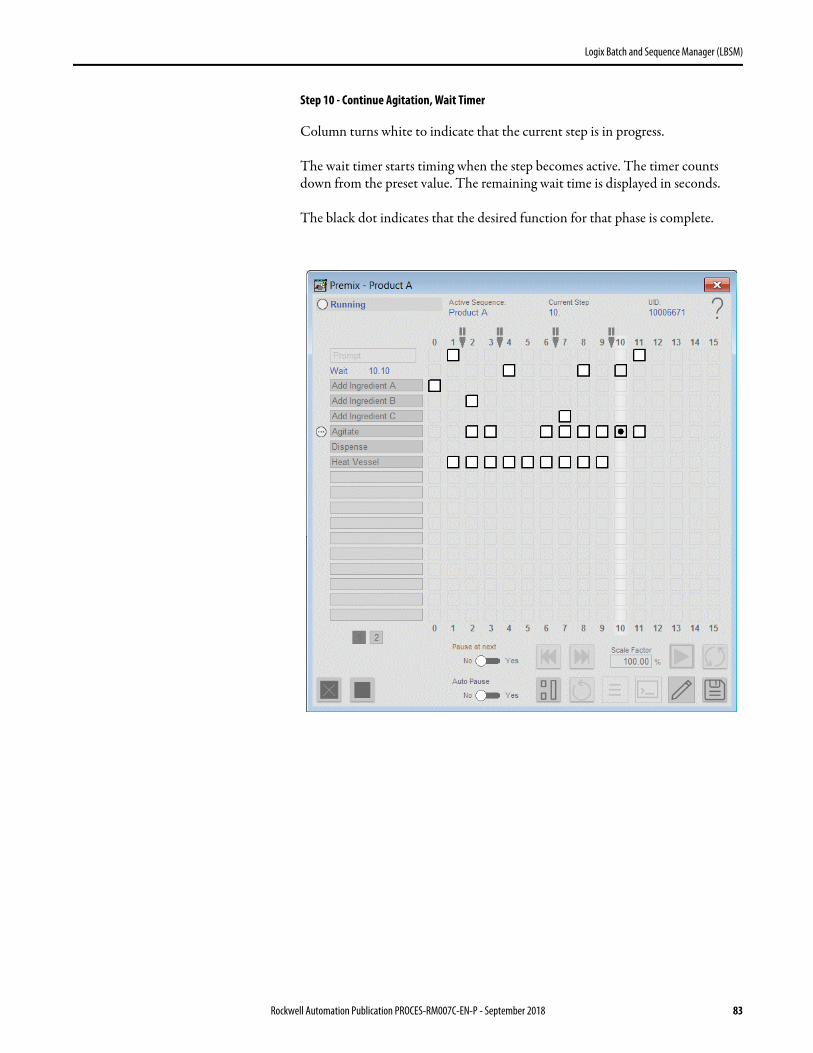
Logix Batch and Sequence Manager (LBSM)
Step 10 - Continue Agitation, Wait Timer
Column turns white to indicate that the current step is in progress.
The wait timer starts timing when the step becomes active. The timer counts down from the preset value. The remaining wait time is displayed in seconds.
The black dot indicates that the desired function for that phase is complete.
Rockwell Automation Publication PROCES-RM007C-EN-P - September 2018 83

Logix Batch and Sequence Manager (LBSM)
Step 11 - Continue Agitation, Prompt Acknowledgment
Column turns white to indicate that the current step is in progress.
The black dot indicates that the desired function for that phase is complete.
Click either of the indicators for operator interaction to access the prompt acknowledgment display.
Press the check mark button to acknowledge the response.
84 Rockwell Automation Publication PROCES-RM007C-EN-P - September 2018

Logix Batch and Sequence Manager (LBSM)
Batch Complete
Status box indicates that the procedure is ‘Complete’.
Boxes are cleared for another batch.
The reset button is active. The state can be reset to Idle. The batch state must be in Idle before a new batch can be started.
Rockwell Automation Publication PROCES-RM007C-EN-P - September 2018 85
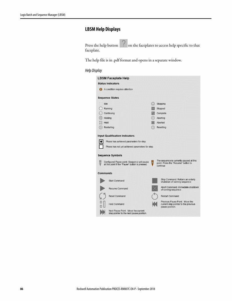
Logix Batch and Sequence Manager (LBSM)
LBSM Help Displays
Press the help button on the faceplates to access help specific to that faceplate.
The help file is in .pdf format and opens in a separate window.
Help Display
86 Rockwell Automation Publication PROCES-RM007C-EN-P - September 2018
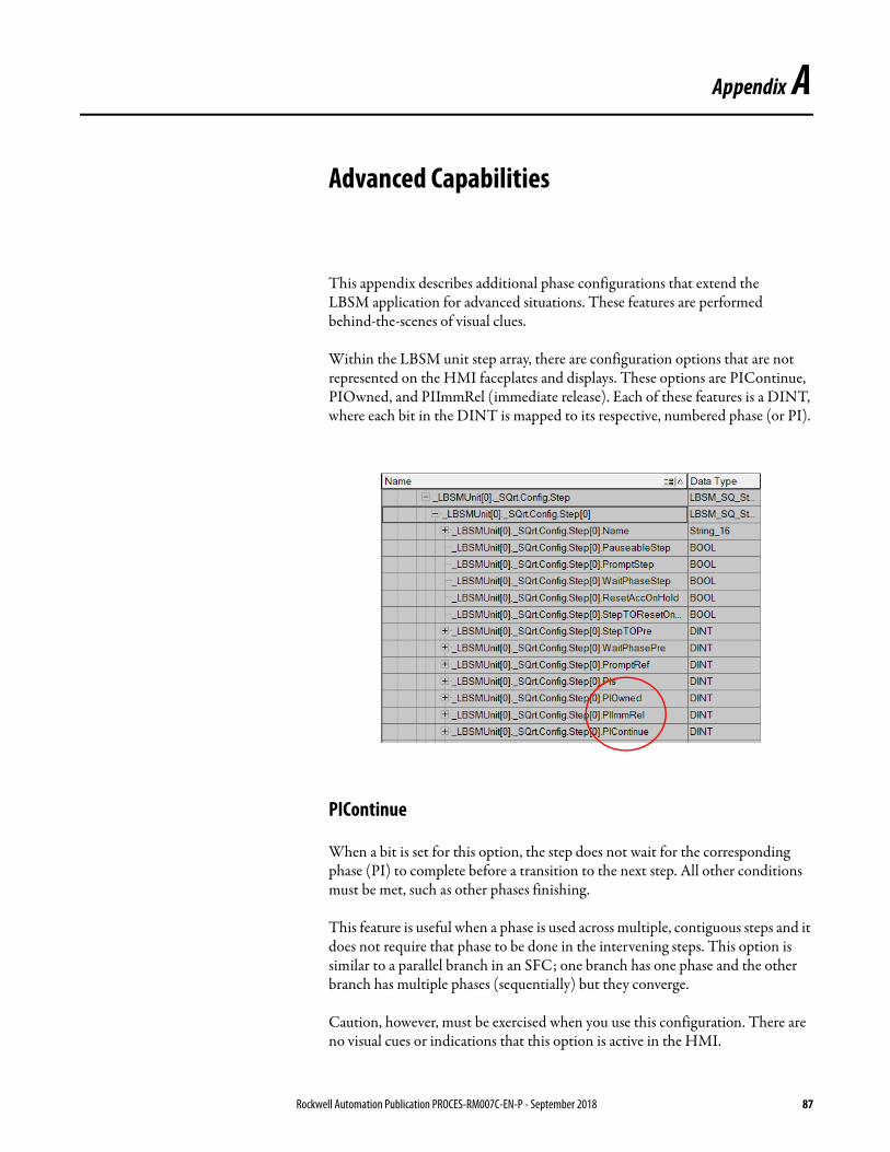
Appendix A
Advanced Capabilities
This appendix describes additional phase configurations that extend the
LBSM application for advanced situations. These features are performed
behind-the-scenes of visual clues.
Within the LBSM unit step array, there are configuration options that are not represented on the HMI faceplates and displays. These options are PIContinue, PIOwned, and PIImmRel (immediate release). Each of these features is a DINT, where each bit in the DINT is mapped to its respective, numbered phase (or PI).
PIContinue
When a bit is set for this option, the step does not wait for the corresponding phase (PI) to complete before a transition to the next step. All other conditions must be met, such as other phases finishing.
This feature is useful when a phase is used across multiple, contiguous steps and it does not require that phase to be done in the intervening steps. This option is similar to a parallel branch in an SFC; one branch has one phase and the other branch has multiple phases (sequentially) but they converge.
Caution, however, must be exercised when you use this configuration. There are no visual cues or indications that this option is active in the HMI.
Rockwell Automation Publication PROCES-RM007C-EN-P - September 2018 87
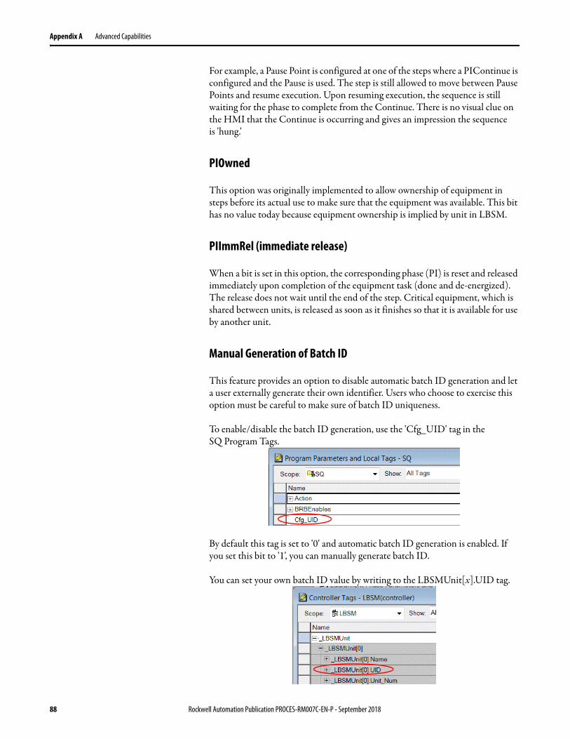
Appendix A Advanced Capabilities
For example, a Pause Point is configured at one of the steps where a PIContinue is configured and the Pause is used. The step is still allowed to move between Pause Points and resume execution. Upon resuming execution, the sequence is still waiting for the phase to complete from the Continue. There is no visual clue on the HMI that the Continue is occurring and gives an impression the sequence
is 'hung.'
PIOwned
This option was originally implemented to allow ownership of equipment in steps before its actual use to make sure that the equipment was available. This bit has no value today because equipment ownership is implied by unit in LBSM.
PIImmRel (immediate release)
When a bit is set in this option, the corresponding phase (PI) is reset and released immediately upon completion of the equipment task (done and de-energized). The release does not wait until the end of the step. Critical equipment, which is shared between units, is released as soon as it finishes so that it is available for use by another unit.
Manual Generation of Batch ID
This feature provides an option to disable automatic batch ID generation and let a user externally generate their own identifier. Users who choose to exercise this option must be careful to make sure of batch ID uniqueness.
To enable/disable the batch ID generation, use the 'Cfg_UID' tag in the
SQ Program Tags.
By default this tag is set to '0' and automatic batch ID generation is enabled. If you set this bit to '1', you can manually generate batch ID.
You can set your own batch ID value by writing to the LBSMUnit[x].UID tag.
88 Rockwell Automation Publication PROCES-RM007C-EN-P - September 2018

Appendix B
Equipment Interface Codes
Equipment Interface Codes
The EM_Composite member of the _Equipment array provides the interface between the LBSM application and your equipment. Your equipment module code must be configured to interface to these tags.
IMPORTANT Details for each member of the EM_Composite data type are shown
in Table 9. Examples for programming the interface are shown in Appendix C
on page 91.
Table 9 - EM_Composite Data Types
Member Data Type Description
EquipmentName String_16 Equipment name that is displayed on the HMI.
Display String_16 For future enhancement.
EMProgReq BOOL Boolean input that requests the Equipment Module use Program mode. This input is used by the
EM Add-On Instruction.
EMProgLReq BOOL Latched version of the EMProgReq
EMOperReq BOOL Boolean input that requests the Equipment Module use Operator mode. This input is used by the
EM Add-On Instruction.
EMOperLReq BOOL Latched version of the EMOperReq
CMReq BOOL Boolean input that requests the CMs use Operator mode. This input is used by the EM Add-On Instruction.
Cmnd BOOL Boolean input that commands the EM to perform its primary function.
ParameterEnable DINT Enabling a parameter makes it active for the equipment module. This action corresponds to EM enable on the Equipment Configuration dialog box.
ParameterNamesReal LBSM_ParameterReal[4] Names of the Real parameters for display on the HMI equipment.
ParameterNamesBool LBSM_ParameterBool[4] Names of the Boolean parameters for display on the HMI equipment.
ParameterValues LBSM_ParameterValues Inputs to the EM that can be modified from the HMI. For example, setpoints.
ActualEnable DINT Enabling an actual value (or report value) makes it active for the equipment module. This corresponds to EM enable on the Equipment Configuration dialog box.
ActualNamesReal LBSM_ParameterReal[4] Names of the values reported to the phases for display on the HMI equipment.
HoldReq BOOL Boolean input that requests the EM to perform its Hold function. This could be to go to a known state or stay where it is (or do nothing).
ResetReq BOOL Boolean input that requests the EM to reset; put the EM into a known initial state, ready to run again.
NewParmsONS BOOL Set by a supervisory entity when new parameters are given to the EM. User program must always reset this tag (set to zero).IMPORTANT: Used as a handshake for upper level supervisors (so they know the EM executed).
Rockwell Automation Publication PROCES-RM007C-EN-P - September 2018 89

Appendix B Equipment Interface Codes
EMProg BOOL Boolean output that indicates the EM is in Program mode.IMPORTANT: The EMProgReq/EMProg interaction is used by the Running routine of the phase to determine the appropriate EM access mode for operation.
EMProgL BOOL Latched version of the EMProg
EMOper BOOL Boolean output that indicates the EM is in Operator mode.IMPORTANT: The EMOperReq/EMOper interaction is used by the Running routine of the phase to determine the appropriate EM access mode for operation.
EMOperL BOOL Latched version of the EMOper
EM BOOL Boolean output that indicates the EM is in the EM mode.
CM BOOL Boolean output that indicates the EM is in the CM mode.
State BOOL Boolean output that indicates that the EM is Off (0) or On (1). Indicates that the EM is performing its primary function as in response to a Cmnd = 1.IMPORTANT: Used by the Stopping routine in the phase to determine when the EM is in the user-definable Off or On state.
DN BOOL Boolean output indicates that the EM has achieved its final state. User program must always set this tag at some point in the operation of the EM.Every EM has a condition or state that is considered its final condition or state. You must define that condition for an individual EM and appropriately condition the DN bit.EMs that 'Run until Done' set the DN bit when its objective is achieved.For example, 'automatically metered ingredient add'.EMs that 'Run until Stop' set the DN bit immediately or constantly.For example, 'agitator'.EMs that 'Run until Done, Continue until Stop' set the DN bit when its objective is achieved.For example, 'Slow reacting temperature loop' (it is 'DN' when at SP but continues to regulate until told
to stop).The DN must be reset whenever the Cmnd bit is low.The DN can go low as the result of receiving new parameters that indicate a new objective, as defined by user logic.IMPORTANT: The Cmnd/DN interaction tells a phase that the EM has performed the requested action. The phase sets the Cmnd and waits to see a DN to know that the EM has performed the requested action.
Actual LBSM_ActualValues Outputs from the EM that are used by the phase. For example, a control variable, such as temperature or speed.
ResetDN BOOL Boolean output that indicates that the EM has been reset.The ResetDN is reset whenever the ResetReq is low.IMPORTANT: The ResetReq/ResetDN interaction is used by the Resetting routine of the phase to determine that the EM has been reset.
Held BOOL Boolean output that indicates that the EM is in a state that is caused by the setting of the HoldReq input.Held is reset whenever HoldReq is low and the EM has resumed normal operation.IMPORTANT: The HoldReq/Held interaction is used by the Holding and Restarting routines of the phase to determine that the EM is in the correct states.
Fault BOOL Indicates an EM fault. Could be the OR'ed composite of all EM component faults.
LEMFault BOOL Latched version of the Fault
Health BOOL Indicates bad EM health. Could be the OR'ed composite of all EM component health bits (like CM I/O
health bits).
Exists BOOL Bit that is set if the controller has code that uses this EM interface and is executing.
MyIndex DINT Set automatically by the LBSM code.
MyUnit DINT Set automatically by the LBSM code.
AcquisitionTO FBD_TIMER This timer, which starts when ownership of the EM is requested, is used for acquiring ownership of the EM. If ownership is not confirmed within this amount of time, a fault is issued.
CmndTO FBD_TIMER This timer, which starts when the command is issued, is used for completion of a command. If the command is not completed within this amount of time, a fault is issued.
Table 9 - EM_Composite Data Types
Member Data Type Description
90 Rockwell Automation Publication PROCES-RM007C-EN-P - September 2018
Appendix C
Bit Interface Examples
The following examples illustrate the basic usage of the bit interface if you are not using PhaseManager™ software.
‘Add Ingredient’ Example
An ingredient addition function can be comprised of one valve or the combination of a pump, valve, and totalizer. Either way, you must define
these functions:
• How much ingredient to add (ParameterValue)
• When to go (Cmnd=1)
• When to temporarily suspend its operation, if needed (HoldReq = 1)
• When to stop (Cmnd = 0)
• When to reset any persistent functionality (ResetReq = 1)
You need to monitor these activities:
• The group is actively functioning or energized (State)
• The group accomplishes what you requested (DN)
• How much ingredient it actually adds (ActualValue)
• When it achieves a temporary suspension of activity (Held)
• When it resets its internal functions (ResetDn)
• Whether any device faults occur (Fault)
Rockwell Automation Publication PROCES-RM007C-EN-P - September 2018 91

Appendix C Bit Interface Examples
Run Until Done Example
This example uses a timer as the equipment.
The functionality of this piece of equipment is what is required of any equipment that runs and finishes on its own (and 'Complete' a commanding phase). Usually this type of equipment is used in one step and its functionality does not span contiguous steps, although it can span contiguous steps in non-continuous operation.
This type of equipment must be reset before running again. 'Ingredient Add' is an example of this type of equipment.
Function Block
Table 10 - Run Until Done Specification Example
Specification Description
Input Time in milliseconds to run (timer.PRE).
Output Accumulated time (timer.ACC).
Runtime functionality When the Cmnd bit is set, run the timer.Set the State bit while the timer is running (timer.ACC = 1).Set the DN bit when the timer is done (timer.DN = 1).
Hold functionality When the HoldReq bit is set, hold the timer where it is and set the Held bit.
Reset functionality When the ResetReq bit is set, reset the timer (and set the ResetDN.bit).
NewParms functionality Not used because the intent of this equipment functionality is to run once and complete (requiring a reset and another start to run again).
92 Rockwell Automation Publication PROCES-RM007C-EN-P - September 2018

Bit Interface Examples Appendix C
Ladder Logic
Structured Text
Rockwell Automation Publication PROCES-RM007C-EN-P - September 2018 93
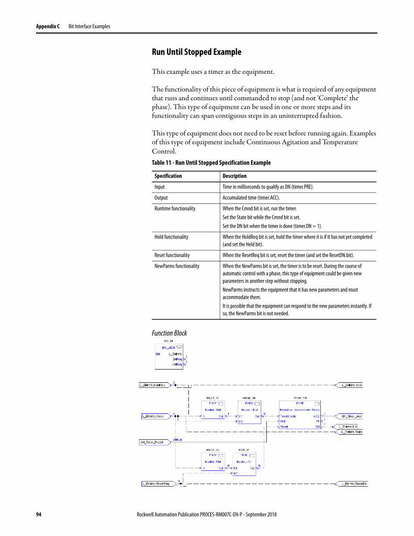
Appendix C Bit Interface Examples
Run Until Stopped Example
This example uses a timer as the equipment.
The functionality of this piece of equipment is what is required of any equipment that runs and continues until commanded to stop (and not 'Complete' the phase). This type of equipment can be used in one or more steps and its functionality can span contiguous steps in an uninterrupted fashion.
This type of equipment does not need to be reset before running again. Examples of this type of equipment include Continuous Agitation and Temperature Control.
Function Block
Table 11 - Run Until Stopped Specification Example
Specification Description
Input Time in milliseconds to qualify as DN (timer.PRE).
Output Accumulated time (timer.ACC).
Runtime functionality When the Cmnd bit is set, run the timer.Set the State bit while the Cmnd bit is set.Set the DN bit when the timer is done (timer.DN = 1).
Hold functionality When the HoldReq bit is set, hold the timer where it is if it has not yet completed (and set the Held bit).
Reset functionality When the ResetReq bit is set, reset the timer (and set the ResetDN.bit).
NewParms functionality When the NewParms bit is set, the timer is to be reset. During the course of automatic control with a phase, this type of equipment could be given new parameters in another step without stopping.NewParms instructs the equipment that it has new parameters and must accommodate them.It is possible that the equipment can respond to the new parameters instantly. If so, the NewParms bit is not needed.
94 Rockwell Automation Publication PROCES-RM007C-EN-P - September 2018

Bit Interface Examples Appendix C
Ladder Logic
Structured Text
Rockwell Automation Publication PROCES-RM007C-EN-P - September 2018 95

Appendix C Bit Interface Examples
Run Until Done, Continue Until Stopped Example
This example uses a timer as the equipment.
The functionality of this piece of equipment is what is required of any equipment that executes as either of the previous two, selected by a parameter. This type of equipment can be used in one or more steps and its functionality can span multiple contiguous steps in an uninterrupted fashion.
This type of equipment could need to be reset before running again. Examples of this type of equipment include Timed/Free Agitation.
Function Block
Table 12 - Run Until Done, Continue Until Stopped Specification Example
Specification Description
Input Time in milliseconds to qualify as DN (timer.PRE).The mode (0 - Timed, 1 - Free Running).
Output Accumulated time (timer.ACC).
Runtime functionality When the Cmnd bit is set, run the timer.Set the State bit while the Cmnd bit is set.Set the DN bit when the timer is done (timer.DN = 1).
Hold functionality When the HoldReq bit is set, hold the timer where it is if it has not yet completed (and set the Held bit).
Reset functionality When the ResetReq bit is set, reset the timer (and set the ResetDN.bit).
NewParms functionality This is not used because the intent of this equipment functionality is to run once and complete (requiring a reset and another start to run again). When the NewParms bit is set, the timer is to be reset. During the course of automatic control with a phase, this type of equipment could be given new parameters in another step without stopping.NewParms instructs the equipment that it has new parameters and must accommodate them.It is possible that the equipment can respond to the new parameters instantly. If so, the NewParms bit is not needed.
96 Rockwell Automation Publication PROCES-RM007C-EN-P - September 2018
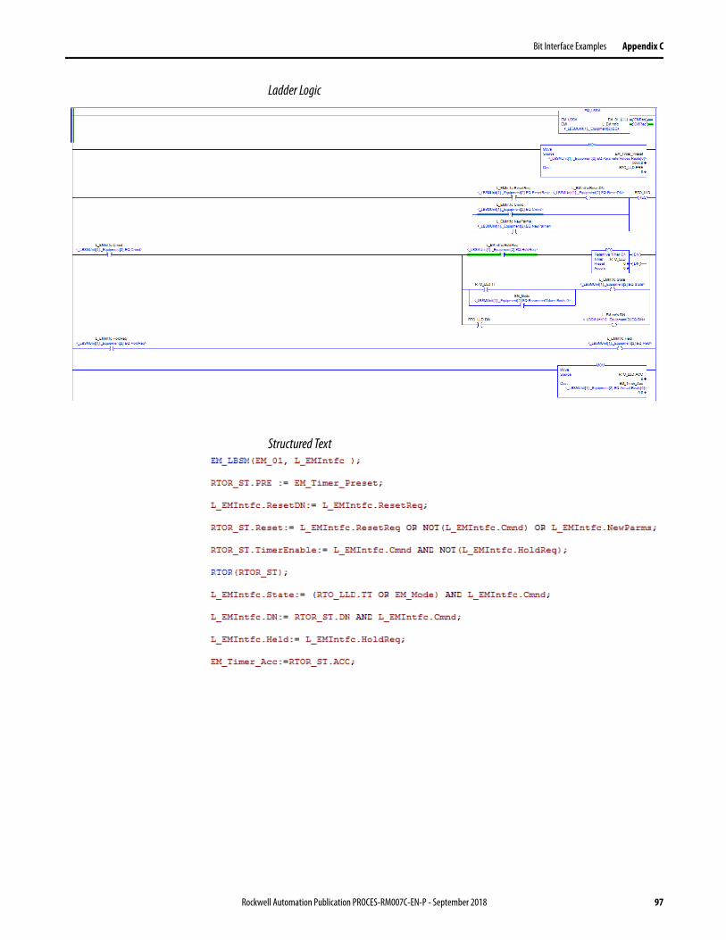
Bit Interface Examples Appendix C
Ladder Logic
Structured Text
Rockwell Automation Publication PROCES-RM007C-EN-P - September 2018 97

Appendix C Bit Interface Examples
Notes:
98 Rockwell Automation Publication PROCES-RM007C-EN-P - September 2018
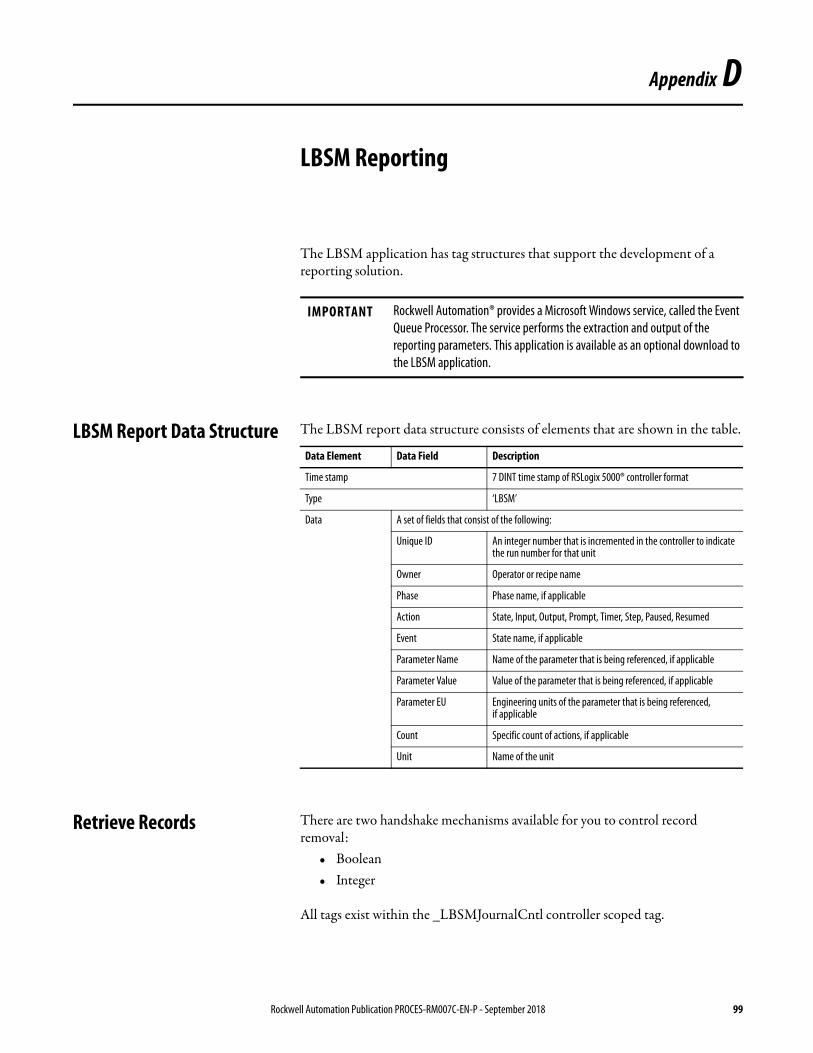
Appendix D
LBSM Reporting
The LBSM application has tag structures that support the development of a reporting solution.
LBSM Report Data Structure The LBSM report data structure consists of elements that are shown in the table.
Retrieve Records There are two handshake mechanisms available for you to control record removal:
• Boolean• Integer
All tags exist within the _LBSMJournalCntl controller scoped tag.
IMPORTANT Rockwell Automation® provides a Microsoft Windows service, called the Event Queue Processor. The service performs the extraction and output of the reporting parameters. This application is available as an optional download to the LBSM application.
Data Element Data Field Description
Time stamp 7 DINT time stamp of RSLogix 5000® controller format
Type ‘LBSM’
Data A set of fields that consist of the following:
Unique ID An integer number that is incremented in the controller to indicate the run number for that unit
Owner Operator or recipe name
Phase Phase name, if applicable
Action State, Input, Output, Prompt, Timer, Step, Paused, Resumed
Event State name, if applicable
Parameter Name Name of the parameter that is being referenced, if applicable
Parameter Value Value of the parameter that is being referenced, if applicable
Parameter EU Engineering units of the parameter that is being referenced, if applicable
Count Specific count of actions, if applicable
Unit Name of the unit
Rockwell Automation Publication PROCES-RM007C-EN-P - September 2018 99
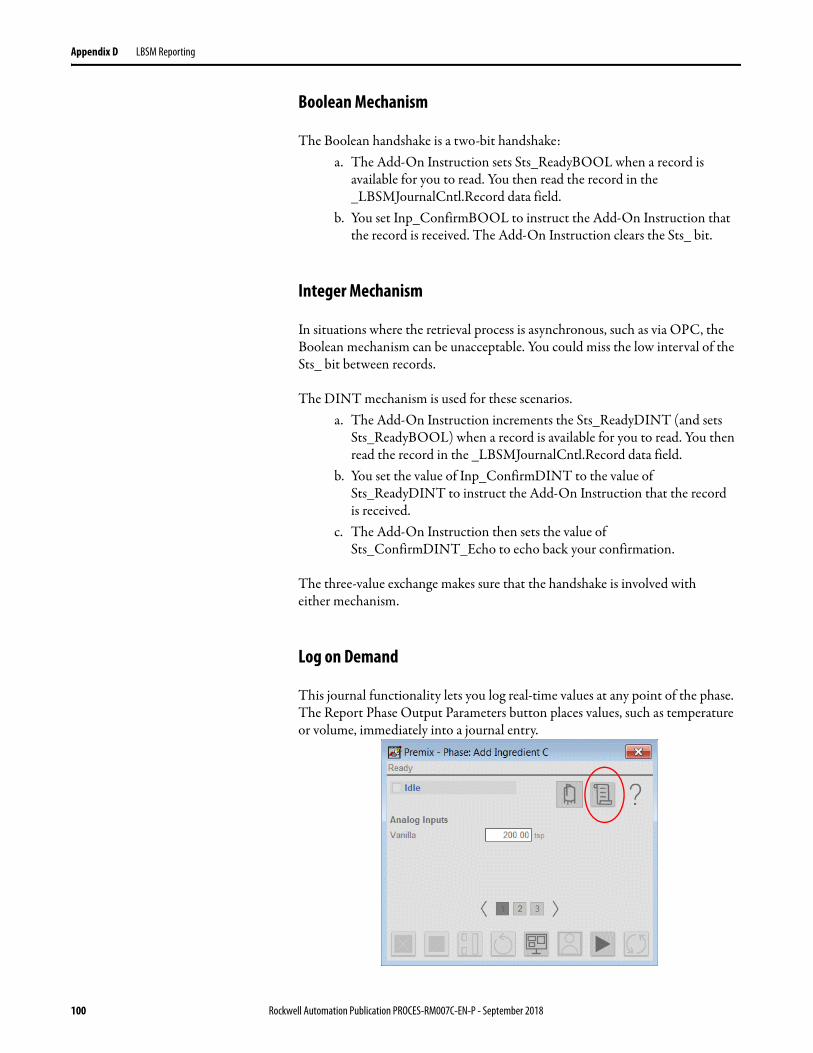
Appendix D LBSM Reporting
Boolean Mechanism
The Boolean handshake is a two-bit handshake:a. The Add-On Instruction sets Sts_ReadyBOOL when a record is
available for you to read. You then read the record in the _LBSMJournalCntl.Record data field.
b. You set Inp_ConfirmBOOL to instruct the Add-On Instruction that the record is received. The Add-On Instruction clears the Sts_ bit.
Integer Mechanism
In situations where the retrieval process is asynchronous, such as via OPC, the Boolean mechanism can be unacceptable. You could miss the low interval of the Sts_ bit between records.
The DINT mechanism is used for these scenarios.a. The Add-On Instruction increments the Sts_ReadyDINT (and sets
Sts_ReadyBOOL) when a record is available for you to read. You then read the record in the _LBSMJournalCntl.Record data field.
b. You set the value of Inp_ConfirmDINT to the value of Sts_ReadyDINT to instruct the Add-On Instruction that the record
is received. c. The Add-On Instruction then sets the value of
Sts_ConfirmDINT_Echo to echo back your confirmation.
The three-value exchange makes sure that the handshake is involved with
either mechanism.
Log on Demand
This journal functionality lets you log real-time values at any point of the phase. The Report Phase Output Parameters button places values, such as temperature or volume, immediately into a journal entry.
100 Rockwell Automation Publication PROCES-RM007C-EN-P - September 2018
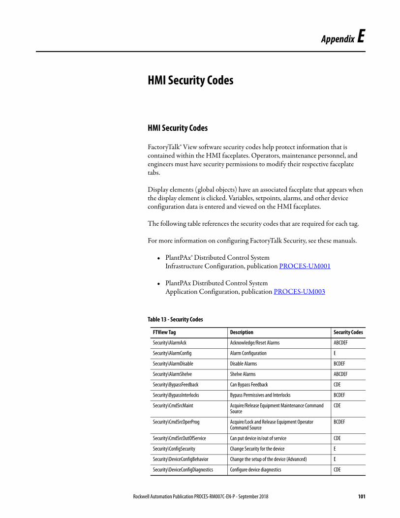
Appendix E
HMI Security Codes
HMI Security Codes
FactoryTalk® View software security codes help protect information that is contained within the HMI faceplates. Operators, maintenance personnel, and engineers must have security permissions to modify their respective faceplate tabs.
Display elements (global objects) have an associated faceplate that appears when the display element is clicked. Variables, setpoints, alarms, and other device configuration data is entered and viewed on the HMI faceplates.
The following table references the security codes that are required for each tag.
For more information on configuring FactoryTalk Security, see these manuals.
• PlantPAx® Distributed Control System Infrastructure Configuration, publication PROCES-UM001
• PlantPAx Distributed Control System Application Configuration, publication PROCES-UM003
Table 13 - Security Codes
FTView Tag Description Security Codes
Security\AlarmAck Acknowledge/Reset Alarms ABCDEF
Security\AlarmConfig Alarm Configuration E
Security\AlarmDisable Disable Alarms BCDEF
Security\AlarmShelve Shelve Alarms ABCDEF
Security\BypassFeedback Can Bypass Feedback CDE
Security\BypassInterlocks Bypass Permissives and Interlocks BCDEF
Security\CmdSrcMaint Acquire/Release Equipment Maintenance Command Source
CDE
Security\CmdSrcOperProg Acquire/Lock and Release Equipment Operator Command Source
BCDEF
Security\CmdSrcOutOfService Can put device in/out of service CDE
Security\ConfigSecurity Change Security for the device E
Security\DeviceConfigBehavior Change the setup of the device (Advanced) E
Security\DeviceConfigDiagnostics Configure device diagnostics CDE
Rockwell Automation Publication PROCES-RM007C-EN-P - September 2018 101

Appendix E HMI Security Codes
Display elements (global objects) have an associated faceplate that appears when the display element is clicked. Variables, setpoints, alarms, and other device configuration data is entered and viewed on the HMI faceplates.
Data cannot be entered or changed without an administrator granting permission with the corresponding security code on each faceplate tab.
Security\DeviceConfigFailTimers Modify Alarm Delay Times DE
Security\DeviceConfigHMI Change the configuration of the HMI interface for the device
E
Security\DeviceConfigLimits Configure device limits DE
Security\DeviceConfigThresholds Modify Limits and Deadbands BCDEF
Security\DeviceConfigTimers Configure device timers DE
Security\DeviceConfigTuning Change Tuning; Inflights; and Preacts DE
Security\EnableSimulation Put Device in Simulation E
Security\EnterOperSettings Enter Setpoints and Control Variables ABCDEF
Security\OperateEquipment Command Equipment in Operator Command Source ABCDEF
Security\OverrideInputs Override Inputs CDE
Security\OverrideOutputs Override Outputs CDE
Security\ProcedureAdvancedExceptions Exception Processing (Step Change; Parameter Change; Acquire; Reorder; Activate)
BCDEF
Security\ProcedureChangeParameters Override Downloaded Phase Parameters BCDEF
Security\ProcedureChangeSetpoints Override Downloaded Setpoints BCDEF
Security\ProcedureControl Select; run; hold; and restart Procedures; Sequences; and Batches
ABCDEF
Security\ProcedureEquipmentControl Manual Supervisory EP/EM Control BCDEF
Security\ProcedureExceptions Exception Processing (Resume; manual; Auto; Semi-Auto; Pause; Disconnect; Release)
ABCDEF
Security\ProcedureForceSequence Force Steps/States BCDEF
Security\ProcedureManualControl Manual Procedure; Sequence; and Batch Processing (Stop; Abort; Reset)
ABCDEF
Security\ResetAccumulators Reset Run Time Accumulators CDE
Security\RespondToPrompts Respond to Prompts ABCDEF
Security\ShowFaceplate Navigate to full faceplate CDE
Table 13 - Security Codes
FTView Tag Description Security Codes
102 Rockwell Automation Publication PROCES-RM007C-EN-P - September 2018
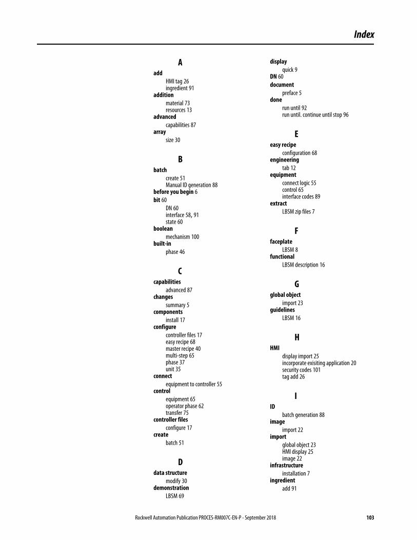
Index
Aadd
HMI tag 26ingredient 91
additionmaterial 73resources 13
advancedcapabilities 87
arraysize 30
Bbatch
create 51Manual ID generation 88
before you begin 6bit 60
DN 60interface 58, 91state 60
booleanmechanism 100
built-inphase 46
Ccapabilities
advanced 87changes
summary 5components
install 17configure
controller files 17easy recipe 68master recipe 40multi-step 65phase 37unit 35
connectequipment to controller 55
controlequipment 65operator phase 62transfer 75
controller filesconfigure 17
createbatch 51
Ddata structure
modify 30demonstration
LBSM 69
displayquick 9
DN 60document
preface 5done
run until 92run until. continue until stop 96
Eeasy recipe
configuration 68engineering
tab 12equipment
connect logic 55control 65interface codes 89
extractLBSM zip files 7
Ffaceplate
LBSM 8functional
LBSM description 16
Gglobal object
import 23guidelines
LBSM 16
HHMI
display import 25incorporate exisiting application 20security codes 101tag add 26
IID
batch generation 88image
import 22import
global object 23HMI display 25image 22
infrastructureinstallation 7
ingredientadd 91
Rockwell Automation Publication PROCES-RM007C-EN-P - September 2018 103
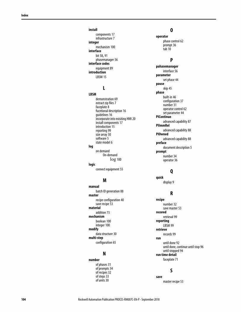
Index
installcomponents 17infrastructure 7
integermechanism 100
interfacebit 58, 91phasemanager 56
interface codesequipment 89
introductionLBSM 15
LLBSM
demonstration 69extract zip files 7faceplate 8fucntional description 16guidelines 16incorporate into exisiting HMI 20install components 17introduction 15reporting 99size array 30software 5state model 6
logon demand
On-demandlog 100
logicconnect equipment 55
Mmanual
batch ID generation 88master
recipe configuration 40save recipe 53
materialaddition 73
mechanismboolean 100integer 100
modifydata structure 30
multi-stepconfiguration 65
Nnumber
of phases 31of prompts 34of recipes 32of steps 33of units 30
Ooperator
phase control 62prompt 36tab 10
Ppahasemanager
interface 56parameter
set phase 44pause
skip 45phase
built-in 46configuration 37number 31operator control 62set parameter 44
PIContinueadvanced capability 87
PIImmReladvanced capability 88
PIOwnedadvanced capability 88
prefacedocument description 5
promptnumber 34operator 36
Qquick
display 9
Rrecipe
number 32save master 53
recoredretrieval 99
reportingLBSM 99
retrieverecords 99
rununtil done 92until done, continue until stop 96until stopped 94
run time detailfaceplate 71
Ssave
master recipe 53
104 Rockwell Automation Publication PROCES-RM007C-EN-P - September 2018
Index
security codesHMI 101
setphase parameter 44wait timer 50
sizeLBSM array 30
skippause 45
softwareLBSM 5
statebit 60
state modelLBSM 6
stepnumber 33
stoprun until 94
summary of changes 5
Ttab
engineering 12operator 10
timerset wait 50
transferof control 75
UUDT
number of equipment phases in unit 36unit
configuration 35equipment phases UDT 36number 30
user-defined data types 36
Wwait
set timer 50
Zzip files
LBSM extraction 7
Rockwell Automation Publication PROCES-RM007C-EN-P - September 2018 105

Index
Notes:
106 Rockwell Automation Publication PROCES-RM007C-EN-P - September 2018

Publication PROCES-RM007C-EN-P - September 2018Supersedes Publication PROCES-RM007B-EN-P - May 2016 Copyright © 2018 Rockwell Automation, Inc. All rights reserved. Printed in the U.S.A.
Rockwell Automation Support
Rockwell Automation provides technical information on the Web to assist you in using its products. At http://www.rockwellautomation.com/support you can find technical and application notes, sample code, and links to software service packs. You can also visit our Support Center at https://rockwellautomation.custhelp.com/ for software updates, support chats and forums, technical information, FAQs, and to sign up for product notification updates.
In addition, we offer multiple support programs for installation, configuration, and troubleshooting. For more information, contact your local distributor or Rockwell Automation representative, or visit http://www.rockwellautomation.com/services/online-phone.
Installation Assistance
If you experience a problem within the first 24 hours of installation, review the information that is contained in this manual. You can contact Customer Support for initial help in getting your product up and running.
New Product Satisfaction Return
Rockwell Automation tests all of its products to help ensure that they are fully operational when shipped from the manufacturing facility. However, if your product is not functioning and needs to be returned, follow these procedures.
Documentation Feedback
Your comments will help us serve your documentation needs better. If you have any suggestions on how to improve this document, complete this form, publication RA-DU002, available at http://www.rockwellautomation.com/literature/.
United States or Canada 1.440.646.3434
Outside United States or Canada Use the Worldwide Locator at http://www.rockwellautomation.com/rockwellautomation/support/overview.page, or contact your local Rockwell Automation representative.
United States Contact your distributor. You must provide a Customer Support case number (call the phone number above to obtain one) to your distributor to complete the return process.
Outside United States Please contact your local Rockwell Automation representative for the return procedure.
Rockwell Otomasyon Ticaret A.Ş., Kar Plaza İş Merkezi E Blok Kat:6 34752 İçerenköy, İstanbul, Tel: +90 (216) 5698400
Rockwell Automation maintains current product environmental information on its website at http://www.rockwellautomation.com/rockwellautomation/about-us/sustainability-ethics/product-environmental-compliance.page.
Allen-Bradley, FactoryTalk, Logix 5000, PhaseManager, Plant PAx, RSLinx, Rockwell Software, Rockwell Automation, SequenceManager, and Studio 5000 Logix Designer are trademarks of Rockwell Automation, Inc.
Trademarks not belonging to Rockwell Automation are property of their respective companies.