plans preparation manual - california department of ... preparation manual (u.s. customary units)...
TRANSCRIPT

Plans Preparation Manual (U.S. Customary Units)
Chapter 2 – Project Plans March 2018
2-1
CHAPTER 2
PROJECT PLANS
The purpose of Chapter 2 is to provide the
designer with the policies and procedures to
present design information on a final set of
project plans.
This manual not only covers drafting standards
for the presentation of the design of a project
but also the policy and procedures related to the
design and construction of a project. For more
detailed information, refer to "Contract Plan
Files" in Section 1-1.8 of this manual.
SECTION 2-1
POLICIES AND PROCEDURES FOR
PREPARING PROJECT PLANS
2-1.0 Application of Plan Preparation
Standards
The categories of plan preparation standards, as
used in this manual, are defined as:
Boldface Standards - Standards that are
essential to produce a complete, concise and
legal set of project plans. Boldface standards
use the words "shall" or "must."
Underlined Standards - Standards that are
also important, but allow some flexibility to
be compatible with the procedures and
practices for the preparation of project plans.
Underlined standards use the word "should."
Permissive Standards - All standards other
than boldface or underlined. Permissive
standards use the word "may."
For a more detailed clarification of manual
standards, see Section 1-1.2 of this manual.
2-1.1 Composition of Project Plans and
General Preparation Procedures
Project plans contain plan sheets that are
specific to that advertised project. Project plan
sheets contain details and dimensions specific to
the project work. Project plans are
supplemented by the Caltrans Standard Plans.
Do not include the drawing of a standard detail
as it is shown in the Caltrans Standard Plans.
The project plans need only call out the name of
that particular standard detail (example: HMA
Dike, Type A), when applicable to the project.
If a standard detail needs to be modified and
included in a specific project, follow the
instructions in "Use of Standard Plans" in
Section 2-1.4 of this manual.
A set of project plans needs to be complete and
concise and to clearly identify all bid items that
a competent contractor can easily interpret and
build. Eliminate extraneous information not
directly related to that specific project plan
sheet. Background topography should not
generally be shown much beyond the right of
way unless the design or construction of the
project (or specific sheet) requires it. The
ultimate goal is to communicate clearly with
bidders, contractors, and the Resident Engineer.
All projects must have at least two sheets, a title
sheet and one other sheet showing proposed
work. A utility plan sheet may be a third sheet
required for all projects, see Sections 2-1.8 and
2-2.13 of this manual.
The layouts are the base plan sheets and all plan
sheet information can be shown on them. If the
layouts become too crowded or cluttered, other
plan sheets are to be used to clearly show the
proposed work (i.e. drainage, pavement
delineation, signing, etc).

Plans Preparation Manual (U.S. Customary Units)
Chapter 2 – Project Plans March 2018
2-2
Some projects do not need layouts to show the
proposed work. If the typical cross sections,
details and quantity sheets (along with the
special provisions) clearly and concisely convey
and explain the proposed work, then layouts (or
any other plan sheets) may not be necessary.
When possible, group similar or inter-related
bid items on the same plan sheets (i.e. pavement
delineation and signing). The fewer and simpler
the sheets, the more concise and understandable
the final plans will be. However, avoid placing
too much information on a plan sheet just to
save paper. Make sure that all of the bid items
shown on the plan sheet are under the purview
of the individual signing and approving the
sheet. If not, separate the bid items so each
licensed individual is signing for the bid items
under his/her purview.
Do not include plan sheets that do not contain
work to be performed as part of the project, not
even layouts, since it adds no value to the bidder
or contractor and may cause confusion. Use
break line symbols and gaps in stationing on the
plan sheets to reflect the length of highway
where no work is to be performed. Not all
layout sheets will have corresponding drainage,
utility, and pavement delineation sheets. If
there is no work of that nature being performed
on that portion of the project, do not show that
kind of sheet for that length of highway. A
good key map eliminates any confusion on the
number of sheets for each type of plan sheet
work (layout, drainage, pavement delineation,
signing, etc.), and shows how these sheets are
arranged.
All bid items must be clearly identified so
quantities can be determined from the labeling
and dimensioning on plan, profile or detail
sheets. A bidder or contractor shall never be
required or expected to scale from a hard copy
print of the project plans in order to determine a
quantity.
Labeling of bid items identified on plan, profile,
and detail sheets must be consistent with the
labeling as it appears in the quantity tables, the
bid item list and special provisions. Quantities
should be easy to identify, calculate and locate
for all bid items.
In general, when identifying physical features,
first describe the item, then the spacing, and
then the total number of items (i.e. 10' steel
poles @ 20' centers, total 4). See Section 2-1.3
for additional instructions for dimensioning and
locating construction features.
Where stationing identifies bid items, plan
sheets must include alignment lines so that plus
stations or offset distances can be referenced to
known stationing. Minor projects, designed
using only post miles in place of stationing,
must identify locations to a hundredth of a post
mile. An alignment line labeled with post miles
is to be shown in place of showing stationing.
If the quantity for the same bid item is shown on
more than one type of plan sheet or quantity
table (i.e. roadway, landscape or structures), the
sub-totals from each quantity table are to be
added together and displayed as a grand total on
the quantity table most logically associated with
that bid item (usually on the summary of
quantities).
If there is a discrepancy between the project
plans and the special provisions, the special
provisions take precedence in any claim or
disagreement between the contractor and the
Department. When developing a set of project
plans, the project engineer must keep in mind
the special provisions and how these two parts
complement each other. Do not add
specifications on the plans. They belong in the
project special provisions. Plans graphically
show bid items and identify their locations.
Specifications identify how a bid item is to be
paid for and how it is to be constructed,
installed, placed, etc.

Plans Preparation Manual (U.S. Customary Units)
Chapter 2 – Project Plans March 2018
2-3
Right of Way
Except for indeterminate right of way, as
described herein, defined right of way must be
shown on:
The layout sheets of the project plans or
if there are no layouts, the first set of
plan view sheets. If there are no plan
view sheets, then on the typical cross
sections or first detail sheets.
Other plan view sheets (in addition to
the layouts), if the defined right of way
has an impact on the work shown on
those specific sheets.
Defined right of way, except indeterminate right
of way, shown on a plan view sheet shall be
depicted with a solid line and the R/W label
above or below the line (not within Caltrans
right of way) with no leader line and arrow.
With the exception of indeterminate right of
way, plan view sheets that depict defined right
of way lines are to include the following note,
"FOR ACCURATE RIGHT OF WAY DATA,
CONTACT RIGHT OF WAY ENGINEERING
AT THE DISTRICT OFFICE." Use of this note
on all plan view sheets is necessary to notify
subcontractors who typically perform work
shown only on one particular type of plan sheet
(example: Electrical Systems). These
subcontractors typically do not receive the
project layout sheets that include this note.
In some instances, the right of way will be
indeterminate (i.e. right of way is by implied
dedication – which basically means Caltrans
does not own the property on which the
highway is located). In these instances, the right
of way lines are not to be shown, and the
following note is to be placed on the layout
sheets: "RIGHT OF WAY LIMITS ARE
INDETERMINATE, AND ARE NOT
SHOWN. THE CONTRACTOR MUST
CONTACT RIGHT OF WAY ENGINEERING
AT THE DISTRICT OFFICE FOR
CONDITIONS OF USE PRIOR TO
COMMENCING WORK."
The defined right of way note or the
indeterminate right of way note, as applicable to
the project, should be placed in the upper left
corner of the plan view sheet. Do not use the
indeterminate right of way note just because
sufficient time was not allotted to properly
research the right of way.
Railroad Involvement
Negotiations with railroad companies are
usually long and involved. The District Right of
Way Railroad Agent must be contacted early in
the project design phase, if:
An existing railroad facility (example:
at-grade crossing, underpass, or
overhead) is within the project limits or
immediately adjacent to the project
A new railroad facility is to be
constructed within the project limits.
In most instances, when a railroad facility is
shown on the title sheet of the project, it is
generally for the purpose of geographical
reference (identifiable point or landmark), but it
may also indicate that railroad clearances need
to be addressed. If a railroad facility is shown
on the layout sheets of the project plans, then it
would definitely indicate railroad involvement,
directly or indirectly.
Railroad clearance will need to be addressed in
those situations where project construction:
Will impact traffic at any railroad grade
crossing that is adjacent to or within the
limits of highway construction
Requires entry of railroad property for
access to the work
Involves the attachment of guard railing
to the abutment of an underpass, jacking
of a pipe beneath the railroad roadbed, or
construction of fences adjacent to
railroad property

Plans Preparation Manual (U.S. Customary Units)
Chapter 2 – Project Plans March 2018
2-4
If a railroad is shown on the title sheet of the
project plans and project construction does not
impact the railroad facility, as determined by the
District Right of Way Railroad Agent, then
railroad clearance could be in the form of a
single page letter stating that there is no railroad
involvement.
2-1.2 Drafting Standards
Good drafting can enhance and clarify the
readability of the project plans. A perfectly
engineered project is only perfect if it can be
easily read and understood by the bidders,
winning contractor and the construction
inspector. While developing the project, the
designer must always keep in mind the people
who will read and interpret the plans.
Clarity and consistency are two of the important
aspects of good drafting practices.
Consistency statewide in following Caltrans
drafting standards (which augments basic
drafting standards) when developing project
plans will promote clarity and familiarity with
all Caltrans advertised projects.
Drafting standards include:
Line weights, line styles and graphical
representations of features conforming to the
CADD Users Manual, the Standard Plans
and this manual.
● Abbreviations, acronyms, symbols and
symbologies are to conform to Standard
Plans A3A through A3C (formally A10A
through A10E, H1 and H2, and ES-1A
through ES-1C). Caltrans has established,
by long-standing practice, the use of an
uppercase letter at the beginning of a single
word abbreviation followed by lowercase
letter(s). In the case of multiple word
abbreviations or acronyms, Caltrans uses all
uppercase letters.
● Text sizes conform to Section 2-6 of the
CADD Users Manual. Caltrans uses
uppercase text for projects. Use of
uppercase text makes it easier to distinguish
characters within the callouts, dimensioning,
and labeling in the contract plans.
● Placement of text, as shown in Figure 2-1,
typically reads left to right. Some numeric
text is placed along vertical lines (i.e. BC
and EC alignment annotation and
matchlines). This text reads bottom to top.
● Placement of text is to be consistent and
legible throughout the project. Text is
generally placed above the line work, if a
leader line is not used. Where a leader line
is used to label a bid item or the limits of a
bid item, place the leader line so that the text
will read from left to right.
● Placement of text should not break line work
or shapes, or interfere with other text or
annotation.
● Sheet match lines are to be placed
perpendicular to the alignment line (station
line or layout line). Sheet match lines are
not to be placed at a full station, because the
match line would obscure the station
annotation and station tick mark. The match
line break should be located halfway
between station tick marks (i.e. +50).
● Placement of legends, notes or disclaimer
information on plan sheets should be
consistent for all projects.
● Leader lines with or without arrowheads are
used to label bid items. Use of arrowheads
should be dependent on whether their
addition would create more clutter and
reduce the legibility of the information to be
shown. Leader lines without arrowheads are
generally used to identify station limits of an
item of work. Be consistent in the use of
leader lines and arrowheads.

Plans Preparation Manual (U.S. Customary Units)
Chapter 2 – Project Plans March 2018
2-5
Begin and end points of bid items are to
be shown on the plans. Identify begin
and end points of bid items using plus
stations and offset distances from the
alignment control line. If the alignment
of the bid item coincides with the
alignment control line, offset distance is
not used. Plus stations and offset
distances are to be shown to the nearest
foot or tenth of a foot depending on the
type of work. In those cases where a
greater degree of accuracy is needed,
identify begin and end limits of bid
items or offset distances to hundredths of
a foot. Where multiple bid items begin
or end at the same plus station, use one
extension line from the plus station to
identify each bid item in a stacked
group. If sheets are really cluttered, an
alternative method is to identify only the
begin point of the bid items and include
the overall actual length of each bid
item. Be consistent within each plan set
type (layouts, drainage, signs, pavement
delineation, etc.) in the method used to
identify locations of the bid items.
FIGURE 2-1
TEXT PLACEMENT AND READING DIRECTION

Plans Preparation Manual (U.S. Customary Units)
Chapter 2 – Project Plans March 2018
2-6
2-1.3 U.S. Customary Unit Standards
Dimensions
Dimensions of existing features should reflect
their actual values. Dimensions of new features
should reflect the required values to accurately
construction the feature. Dimensioning, in
general, should reflect the accuracy of the
equipment required to construct the feature.
The use of feet and decimals of a foot for
dimensions versus the use of feet and inches
should be based on the bid item involved.
Pavement structure work is to be dimensioned
by the foot and decimals of foot (see Section
2-2.3 Typical Cross Sections).
Formed concrete construction features (bridges,
walls, drainage features, curbs, sidewalks, etc.)
are dimensioned in feet, inches and fractions of
inches. Generally, manufactured or fabricated
items are dimensioned in feet, inches and
fractions of inches. The Caltrans Standard Plans
should be used as a guide to determine whether
a dimension should be expressed in feet and
decimals of a foot or feet and inches.
Dimensions in feet, tenths of a foot or
hundredths of a foot are to be shown with an
accompanying apostrophe (symbol for foot).
Where a dimension is to be displayed in tenths
or hundredths of a foot and the dimension is less
than one foot, use a zero in front of the decimal
point (example: 0.2', 0.35').
Dimensions in inches are to be shown with an
accompanying quotation mark (symbol for
inch). Where a dimension is to be displayed in
feet and inches and the dimension is one foot or
greater, place a hyphen between the foot and
inch values, (example: 1'-0", 2'-3", 10'-1/2").
Where a dimension is displayed in inches and
the dimension is less than one foot, do not use
the foot designation or hyphen in advance of the
inch value, (example: 6", not 0'-6"). Do not use
notes such as, "ALL DIMENSIONS ARE IN
FEET UNLESS OTHERWISE SHOWN," on
the project plan sheets.
Fractions of a foot are not to be used in
dimensioning (example: 101/2'). Fractions of an
inch are acceptable but decimal inches are not
used on project plan sheets.
Locations of Construction Features
With the exception of those instances where
construction is located by post miles or in those
more rare instances where construction features
are located by distance offsets from fixed
objects, construction features are to be located
using stationing and, as applicable to the bid
items, plus stations and offset distances from
alignment lines. Depending on the accuracy
required, construction features are shown to the
nearest foot, tenths of foot or hundredths of foot.
Horizontal dimensions and offset distances from
an alignment line are to be shown with an
accompanying apostrophe (symbol for foot).
Elevations
Accompanying foot tick marks are not used for
existing or new contour lines, spot elevations, or
for datum elevations shown on the grid lines of
profiles. Depiction of elevations without a foot
tick mark has been established by long-standing
engineering practice. The basis for vertical
control is to be included within the project plans
when elevations are shown.
Bearings of Lines and Angular Identification
Bearings for all alignments shall be Degree-
Minute-Second (plus the direction). Angles
used to depict a detail shall be shown in the
conventional mode (i.e. 57.5o).
Plans Preparation Manual (U.S. Customary Units)
Chapter 2 – Project Plans March 2018
2-7
Cross Slopes
Pavement cross slopes and superelevations shall
be shown as percents.
Side Slopes
Side slopes shall be expressed in a
nondimensional ratio. The horizontal
component is shown first and then the vertical
(X:Y). When a side slope becomes steeper than
1:1, the horizontal component shall be shown as
a fraction such as 3/4:1.
Flares and Tapers
Flares and tapers shall be expressed in a
nondimensional ratio. The longitudinal
component is shown first and then the lateral
offset component (example: 20:1, 15:1, etc.).
Scales
For plan sheets, a horizontal scale of 1" = 50'
(Caltrans standard base scale) should be used in
urban areas and some rural areas. A horizontal
scale of 1" = 20' is used where greater detail is
required than can be shown on the plan layouts.
These sheets would typically be used for
Electrical Systems plans, etc. For projects in
rural areas, a horizontal scale of 1" = 100' may
be used. Where a horizontal scale of 1" = 50' is
used and just a few bid items are involved, the
roadway layout information may be stacked one
above the other on the same plan sheet. The
above three scales are the only scales to be used
for plan view sheets.
For roadway profile sheets, the following scales
are commonly used for the condition described:
Rural sections in hilly or mountainous
terrain: 1" = 10' vertical and 1" = 100'
horizontal
Rural or urban with gentle rolling terrain:
1" = 5' vertical and 1" = 50' horizontal
Rural or urban with level terrain: 1" = 2'
vertical and 1" = 20' horizontal
Vertical to horizontal scale ratios producing
roadway profile grade line plots steeper than 1:1
should be avoided because it overly distorts the
actual field conditions. Scale ratio of horizontal
to vertical (H/V) = 10 is typically used for
roadway profiles.
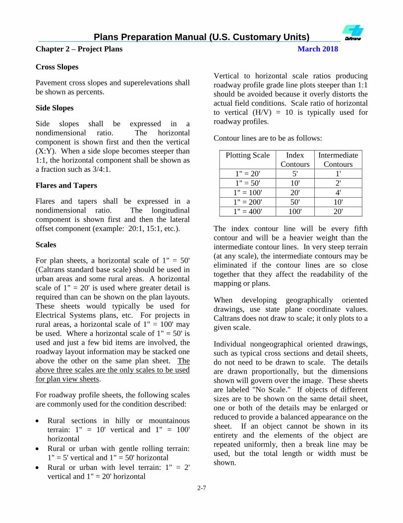
Contour lines are to be as follows:
Plotting Scale Index
Contours
Intermediate
Contours
1" = 20' 5' 1'
1" = 50' 10' 2'
1" = 100' 20' 4'
1" = 200' 50' 10'
1" = 400' 100' 20'
The index contour line will be every fifth
contour and will be a heavier weight than the
intermediate contour lines. In very steep terrain
(at any scale), the intermediate contours may be
eliminated if the contour lines are so close
together that they affect the readability of the
mapping or plans.
When developing geographically oriented
drawings, use state plane coordinate values.
Caltrans does not draw to scale; it only plots to a
given scale.
Individual nongeographical oriented drawings,
such as typical cross sections and detail sheets,
do not need to be drawn to scale. The details
are drawn proportionally, but the dimensions
shown will govern over the image. These sheets
are labeled "No Scale." If objects of different
sizes are to be shown on the same detail sheet,
one or both of the details may be enlarged or
reduced to provide a balanced appearance on the
sheet. If an object cannot be shown in its
entirety and the elements of the object are
repeated uniformly, then a break line may be
used, but the total length or width must be
shown.
Plans Preparation Manual (U.S. Customary Units)
Chapter 2 – Project Plans March 2018
2-8
Earthwork design cross section plotting scales,
both horizontal and vertical, should be 1" = 10'
for rural projects and 1" = 5' for urban projects.
Cross section intervals are not to be greater than
50 feet.
Stationing
Plan sheet stationing is to be based on 100 feet
per station with full annotation at 500-foot
stations (multiple of 5). Annotation at 100 foot
stations is a single digit number (the ones
column). With the exception of precise
stationing required at equations, BCs, ECs, and
POCs, annotation for whole stations shall not
include plus stations (i.e. +00). Refer to the
plan sheet examples in Section 2-2 of this
manual for stationing annotation examples.
Precise stationing in U.S. customary units is
expressed to the hundredth of a foot.
Stationing for preliminary drawings shall also
be based on 100 feet per station and with full
annotation at 500 foot stations for both 1" = 200'
and 1" = 400'. The 100-foot stations do not
need to be annotated.
The length of a station tick mark (in a
MicroStation design file) is 2.8' at 1" = 20'
scale, 7.0' at 1" = 50' scale and 14.0' at 1" = 100'
scale. Station tick marks are centered on the
alignment line. Annotation is placed below the
alignment line. Station annotation is generally
located one-half the height of the text below the
tick mark. For those situations when station
annotations would obscure a construction
feature, the interfering annotations may be
placed further below the tick mark or if
necessary above the station tick mark.
Units of Measurement
The units of measurement as shown on Standard
Plan A3C (formerly A10B) are to be used for
bid items shown on a plan sheet, the quantity
summaries and the Bid Item List so that they
will match those used in the Basic Engineering
Estimating System (BEES). NOTE: The BEES
has field limitations and will not accept upper
and lower case units of measurement so there
may be some differences between the plans and
BEES, but the contract plans are to follow the
convention set forth in the Standard Plans.
2-1.4 Use of Standard Plans
Caltrans Standard Plans are approved
standardized details that are applicable to the
construction of highway facilities. The
Standard Plans are divided into sections
designated by an alpha prefix:
"A"- Pavement delineation, excavation and
backfill details, barriers, guard railing,
crash cushions, fencing, curbs, dikes and
curb ramps
"P" - Pavements
"C" - Crib walls
"D" - Drainage items
"H" - Planting and Irrigation
"T" - Temporary facilities
"B" - Bridge related work, retaining walls, and
sound walls
"RS" - Roadside signs
"S" - Overhead signs and sign panels
"ES" - Electrical systems
All engineers and detailers should have a copy
of the current Standard Plans book and be
familiar with its contents.
The Standard Plans book is updated and issued
at regular intervals, usually between 3-5 years
by the Division of Engineering Services-Office
Engineer (DES-OE). In between the official
releases of the Standard Plans book, revisions,
additions or deletions may occur and are called
a revised standard plan (RSP) that supplements
the current edition of the book. All project
specific applicable RSP sheets must be included
in the advertised contract plan set.
Plans Preparation Manual (U.S. Customary Units)
Chapter 2 – Project Plans March 2018
2-9
The Standard Plans applicable to a specific
project are indicated by the use of the "Standard
Plans List" that is included in the project special
provisions. This list is updated in conjunction
with the issuance of any revised standard plans.
Where revised standard plans are applicable to a
project, they are to be indicated on the
"Standard Plans List." DES-OE will insert the
indicated applicable revised standard plans as
plan sheets into the project plan set. For AADD
projects, the district will be responsible for the
insertion of applicable revised standard plan
sheets as part of the project plan set.
The design section responsible for the project is
to verify that the applicable revised standard
plans are identified on the current "Standard
Plans List" sent to either DES-OE or DOE as
part of the PS&E submittal.
Caltrans standard plans are available via the
Caltrans DES-OE Internet web site in several
electronic formats.
Unsigned MicroStation design files for each
standard plan are provided on the web site to
assist project designers where a standard plan
detail does not fit a given situation and must be
modified. Only the individual modified detail
or details from the standard plan, not the entire
standard plan detail sheet, are to be included on
the applicable detail sheet within the project
plans (construction details, drainage details,
etc.) and labeled "MODIFIED." These detail
sheets containing the individual modified detail
or details based on a standard detail are to be
signed by the licensed individual who made the
decision that a modification was necessary. If
minimal changes are made, show only the
dimensions for the modified portion with a
reference to the applicable standard plan. If
significant changes are made, show all of the
dimensions of the detail. When all dimensions
are shown, reference to the standard plan sheet
is not necessary.
For AADD projects, Caltrans personnel may
access signed tiff file formats of revised
standard plans via the Caltrans internal network
for the submittal of a complete project plan set
in electronic format.
All revised standard plans (RSP) must be
included as part of the advertised project plan
set. This helps ensure that the policy for
including all RSP in the As-Built plans is met,
see Section 4.3 of the CADD Users Manual.
Plans Preparation Manual (U.S. Customary Units)
Chapter 2 – Project Plans March 2018
2-10
THIS PAGE INTENTIONALLY LEFT BLANK

Plans Preparation Manual (U.S. Customary Units)
Chapter 2 – Project Plans March 2018
2-11
2-1.5 Plan Border Sheets
Plan border sheets contained in the Caltrans CADD English Cell Library are to be used for project plan
preparation. Access to the English Cell Library for consultants is available at this web site:
http://www.dot.ca.gov/hq/oppd/cadd/rsc_files/webpage.htm
The figures contained herein depict the various plan border sheets. There may be newer border sheets
than those depicted. Updated border sheets are contained in the Caltrans English Cell Library.
BASIC BORDERS FOR THE PREPARATION OF PROJECT PLANS
FIGURE 2-2A
Border for Title Sheet of Caltrans Prepared Projects
The name of the cell for this title sheet border is AC = TITLE.

Plans Preparation Manual (U.S. Customary Units)
Chapter 2 – Project Plans March 2018
2-12
BASIC BORDERS FOR THE PREPARATION OF PROJECT PLANS
FIGURE 2-2B
Border for Title Sheet of Consultant Prepared Project for Caltrans
The name of the cell for this title sheet border is AC = TITLE2.

Plans Preparation Manual (U.S. Customary Units)
Chapter 2 – Project Plans March 2018
2-13
BASIC BORDERS FOR THE PREPARATION OF PROJECT PLANS
FIGURE 2-2C
Border for Title Sheet of Consultant Prepared Project for Local Agency
The name of the cell for this title sheet border is AC = TITLE3.

Plans Preparation Manual (U.S. Customary Units)
Chapter 2 – Project Plans March 2018
2-14
BASIC BORDER FOR THE PREPARATION OF PROJECT PLANS
FIGURE 2-2D
Border for Most Plan Sheets Prepared by Caltrans
The name of the cell for this border sheet is AC = FULPLN. Use for layouts, typical cross
sections, drainage details, construction details, contour grading, sign plans, quantity sheets, etc.
Plans Preparation Manual (U.S. Customary Units)
Chapter 2 – Project Plans March 2018
2-15
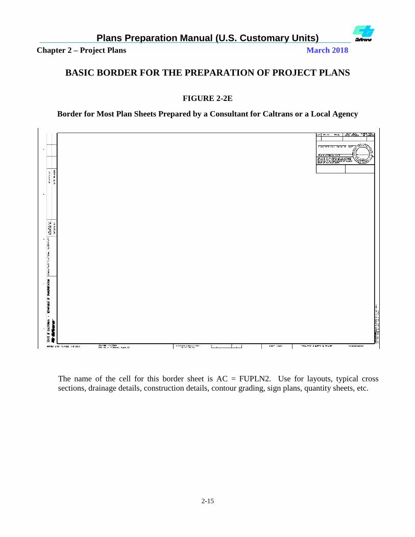
BASIC BORDER FOR THE PREPARATION OF PROJECT PLANS
FIGURE 2-2E
Border for Most Plan Sheets Prepared by a Consultant for Caltrans or a Local Agency
The name of the cell for this border sheet is AC = FUPLN2. Use for layouts, typical cross
sections, drainage details, construction details, contour grading, sign plans, quantity sheets, etc.
Plans Preparation Manual (U.S. Customary Units)
Chapter 2 – Project Plans March 2018
2-16
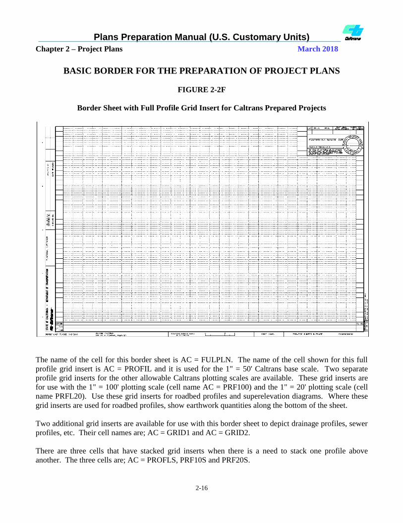
BASIC BORDER FOR THE PREPARATION OF PROJECT PLANS
FIGURE 2-2F
Border Sheet with Full Profile Grid Insert for Caltrans Prepared Projects
The name of the cell for this border sheet is AC = FULPLN. The name of the cell shown for this full
profile grid insert is AC = PROFIL and it is used for the 1" = 50' Caltrans base scale. Two separate
profile grid inserts for the other allowable Caltrans plotting scales are available. These grid inserts are
for use with the 1" = 100' plotting scale (cell name AC = PRF100) and the 1" = 20' plotting scale (cell
name PRFL20). Use these grid inserts for roadbed profiles and superelevation diagrams. Where these
grid inserts are used for roadbed profiles, show earthwork quantities along the bottom of the sheet.
Two additional grid inserts are available for use with this border sheet to depict drainage profiles, sewer
profiles, etc. Their cell names are; AC = GRID1 and AC = GRID2.
There are three cells that have stacked grid inserts when there is a need to stack one profile above
another. The three cells are; AC = PROFLS, PRF10S and PRF20S.

Plans Preparation Manual (U.S. Customary Units)
Chapter 2 – Project Plans March 2018
2-17
BASIC BORDER FOR THE PREPARATION OF PROJECT PLANS
FIGURE 2-2G
Border Sheet with Full Profile Grid Insert for Consultant Prepared
Projects for Caltrans or a Local Agency
The name of the cell for the border sheet is AC = FUPLN2. The name of the cell shown for this full
profile grid insert is AC = PROFL2 and it is used for the 1" = 50' Caltrans base scale. Two separate
profile grid inserts for the other allowable Caltrans plotting scales are available. These grid inserts are
for use with the 1" = 100' plotting scale (cell name AC = PROFL3) and the 1" = 20' plotting scale (cell
name PROFL4). Use these grid inserts for roadbed profiles and superelevation diagrams. Where these
grid inserts are used for roadbed profiles, show earthwork quantities along the bottom of the sheet.
Two additional grid inserts are available for use with this border sheet to depict drainage profiles, sewer
profiles, etc. Their cell names are AC = GRID1C and AC = GRID2C.
There are three cells that have stacked grid inserts when there is a need to stack one profile above
another. The three cells are; AC = PROFL5, PROFL6 and PROFL7.

Plans Preparation Manual (U.S. Customary Units)
Chapter 2 – Project Plans March 2018
2-18
BASIC BORDER FOR THE PREPARATION OF PROJECT PLANS
FIGURE 2-2H
Border Sheet with Partial Profile Grid Insert
NOTES:
1. The name of the cell shown for this border sheet for Caltrans prepared projects is AC = FULPLN. The name of
the cell for the partial profile grid insert shown is AC = PLNPRO. It is used for the 1" = 50' Caltrans base
scale. Two separate partial profile grid inserts for the other allowable Caltrans plotting scales are available.
These grid inserts are for use with the 1" = 100' plotting scale (cell name AC = PLP100) and the 1" = 20'
plotting scale (cell name PLPR20). Use these grid inserts for roadbed profiles and superelevation diagrams.
Superelevation diagrams may be included on the grid profile portion of the sheet where sufficient space is
available and such addition will not produce sheets which are cluttered, unreadable or confusing. Where these
grid inserts are used for roadbed profiles, show earthwork quantities along the bottom of the sheet.
2. For consultant prepared projects for Caltrans or local agency, use the cell named AC = FUPLN2 for the border
sheet. For the partial profile grid inserts, use the cells described in Note 1.
3. Two additional grid inserts are available for use with these border sheets to depict drainage profiles, sewer
profiles, etc. Their cell names are AC = GRID3 and AC = GRID4.
Plans Preparation Manual (U.S. Customary Units)
Chapter 2 – Project Plans March 2018
2-19
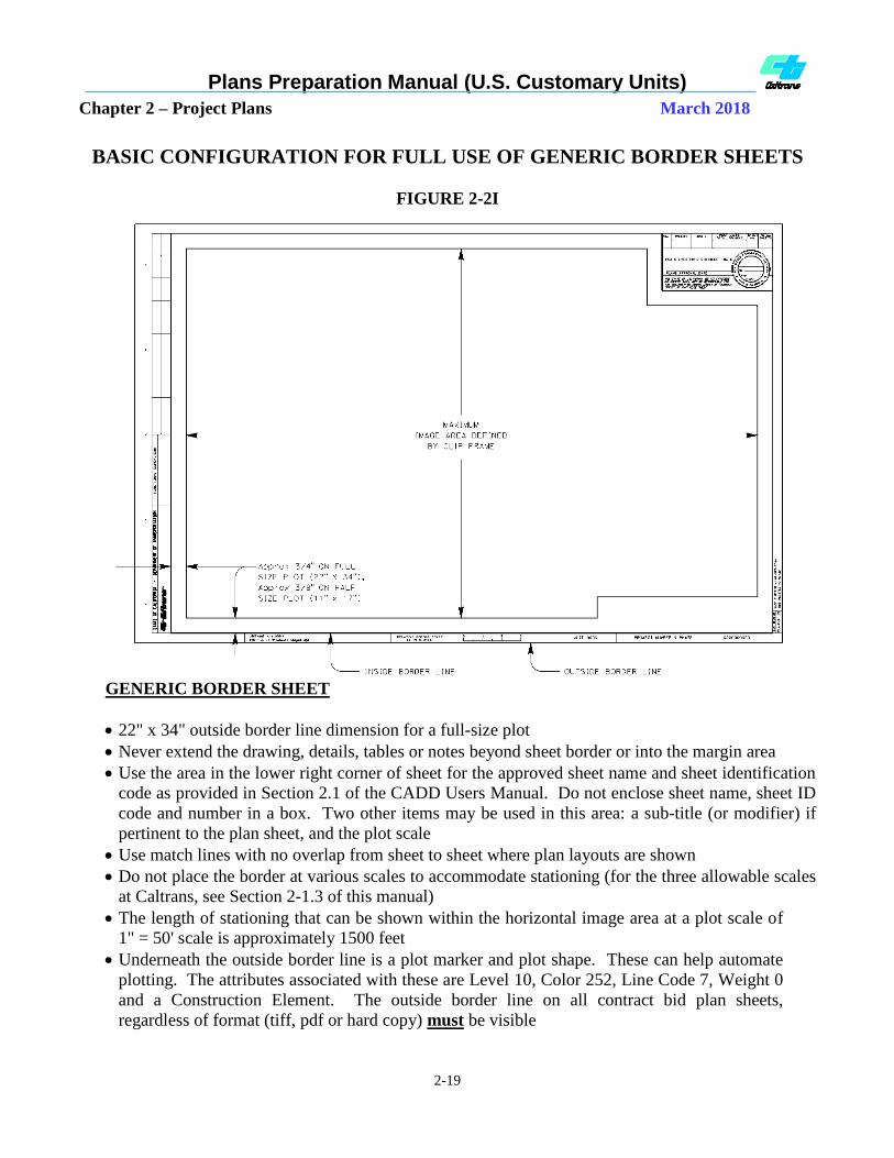
BASIC CONFIGURATION FOR FULL USE OF GENERIC BORDER SHEETS
FIGURE 2-2I
GENERIC BORDER SHEET
22" x 34" outside border line dimension for a full-size plot
Never extend the drawing, details, tables or notes beyond sheet border or into the margin area
Use the area in the lower right corner of sheet for the approved sheet name and sheet identification
code as provided in Section 2.1 of the CADD Users Manual. Do not enclose sheet name, sheet ID
code and number in a box. Two other items may be used in this area: a sub-title (or modifier) if
pertinent to the plan sheet, and the plot scale
Use match lines with no overlap from sheet to sheet where plan layouts are shown
Do not place the border at various scales to accommodate stationing (for the three allowable scales
at Caltrans, see Section 2-1.3 of this manual)
The length of stationing that can be shown within the horizontal image area at a plot scale of
1" = 50' scale is approximately 1500 feet
Underneath the outside border line is a plot marker and plot shape. These can help automate
plotting. The attributes associated with these are Level 10, Color 252, Line Code 7, Weight 0
and a Construction Element. The outside border line on all contract bid plan sheets,
regardless of format (tiff, pdf or hard copy) must be visible

Plans Preparation Manual (U.S. Customary Units)
Chapter 2 – Project Plans March 2018
2-20
BASIC CONFIGURATION FOR USE OF COMBINATION PLAN AND
PROFILE SHEET
FIGURE 2-2J
PLAN AND PROFILE SHEET
22" x 34" outside border line dimension for a full-size plot
Never extend the drawing, details, tables or notes beyond sheet border or into the margin area
Use match lines with no overlap from sheet to sheet where plan layouts are shown
Use the area in the lower right corner of sheet for the approved sheet name and sheet ID code as
provided in Section 2.1 of the CADD Users Manual. Do not enclose sheet name, sheet ID code
and number in a box. Two other items may be used in this area: a sub-title (or modifier) if
pertinent to the plan sheet, and the plot scale. The grid lines do not need to be removed where
this listed information is placed
Do not place the border at various scales to accommodate stationing (for the three allowable
scales at Caltrans, see Section 2-1.3 of this manual)
The length of stationing that can be shown within the horizontal image area at a plot scale of
1" = 50' scale is approximately 1500 feet
The grid portion (lower half) of the sheet is to be used for profiles, superelevation diagrams and
the listing of earthwork quantities along the bottom of the sheet
See Figure 2-2I of this manual regarding sheet plotting

Plans Preparation Manual (U.S. Customary Units)
Chapter 2 – Project Plans March 2018
2-21
2-1.6 Electronically-Generated Plan Sheet
Signatures and Project Development
Names
General
The California Board for Professional
Engineers, Land Surveyors and Geologists
recognizes electronically generated seals as an
acceptable form of the professional seal.
Federal and State laws allow the use of
electronically generated signatures.
Electronically generated seals and signatures
include those affixed to documents through the
use of CADD programs and digital methods.
Title Sheet Signatures
Signature and license seal information on the
title sheet of the project plans identifies the
licensed professional assigned responsibility for
coordinating the effort to produce a complete set
of project plans for construction. Depending on
the type of project, the person signing the title
sheet typically is a licensed civil engineer,
electrical engineer, or landscape architect.
The title sheet serves as a cover sheet for the
project to identify the location(s) where the
work will occur. This sheet is not considered
an engineering document, as no item of work is
to be shown on the sheet (this also applies to
the Locations of Construction sheet). Items of
work are to be shown on other sheets within
the project plans (e.g. Layouts, Drainage,
Electrical Systems, etc.).
Except for the Caltrans design oversight
approval information (signature, license number
and license expiration date) required on
consultant prepared projects for Caltrans (see
Figure 2-7), only one license seal shall appear
on the title sheet. Title sheet borders with the
seal and associated signature information are
available in the Caltrans English Cell Library.
The signature must be electronically affixed to
the title sheet. In all cases, the words
"Registered Civil Engineer," "Registered
Electrical Engineer," "Licensed Landscape
Architect," or equivalent designation must
appear with the signature. See Figures 2-3, 2-4,
and 2-5 for title sheet signature and license seal
information.
Where a consultant prepares a project for
Caltrans or where a firm or local agency
finances and prepares the entire project, their
name and address is to be placed in the lower
right-hand corner of the title sheet (see Figure
2-4).
The prime consultant, that prepares the entire
project for a permittee or local agency, shall
place the company name and address in the
location shown in Figure 2-5 or Title Sheet,
Example "B." Logos, telephone numbers, or
artwork are not permitted.
Title Sheet Project Development Names
For projects prepared by Caltrans, the printed
name of the individual providing oversight of
the Caltrans person assigned responsibility for
coordinating the effort to produce a complete set
of project plans shall be placed in the "Design
Manager" name block space located in the lower
left margin of the title sheet. The printed name
of the Caltrans project manager shall be placed
in the "Project Manager" name block space
located in the lower left margin of the title sheet.
See Figure 2-6 for project development names
required on the title sheet of Caltrans prepared
projects. Printed names included in the name
blocks shall not have any designation indicating
professional status.
For projects prepared by consultants for
Caltrans or local agencies, the printed name of
the individual in the prime consultant’s
company responsible for providing oversight of
the person assigned responsibility for
Plans Preparation Manual (U.S. Customary Units)
Chapter 2 – Project Plans March 2018
2-22
coordinating the effort to produce the complete
set of project plans shall be placed in the
"Consultant Design Manager" name block space
located in the lower left margin of the title sheet.
The Caltrans engineer providing design
oversight approval shall have their printed
name, signature, license number, license
expiration date, and date of signature included
in the block spaces located in the left margin of
the title sheet. The signature must be
electronically affixed to the title sheet. The
design oversight approval note must not be
removed. See Figure 2-7 for project
development names required on the title sheet of
consultant prepared projects.
Individual Plan Sheet Signature
Individual project plan sheets, other than the
title sheet, must have the license seal and
signature of the licensed civil engineer,
electrical engineer, mechanical engineer,
geologist, architect or landscape architect who
has the technical expertise and is in responsible
charge for the preparation of the individual plan
sheet. Licensed traffic engineers can sign traffic
plans (traffic handling, pavement delineation
sheets, etc.). Only one license seal and number
with associated signature shall appear on the
sheet. For all disciplines except Landscape
Architecture, the printed name, license number
and license expiration/renewal date must appear
within the license seal. The registrant's
signature and date signed for the completion of
the sheet shall go outside the license seal but
within the signature block on the line provided
in the upper right hand corner of the sheet
border (see Figure 2-8 or the "Generic Project
Border Sheet" example under the Section 2-2.5
examples).
For Landscape Architecture, the signature,
license renewal date and the date signed for the
completion of the sheet by the licensed
landscape architect shall be within the license
seal. The printed name and license number is
arched above the signature within the seal. A
second signature of the licensed Landscape
Architect shall go outside the license seal but
within the signature block on the line provided
in the upper right hand corner of the sheet
border (see Figure 2-9a).
All advertised project plan sheets (including the
Title Sheet) MUST include the license
expiration date of the person signing and sealing
the sheet. Refer to the December 22, 2009
Memorandum "Inclusion of Expiration Date on
Engineering and Land Surveying Documents"
for the Caltrans business practice of including
the expiration date.
The signature must be electronically affixed to
the plan sheet. In all cases, the words
"Registered Civil Engineer" or equivalent
designation must appear with the registrant's
signature. Do not add job titles such as "Utility
Engineer," "Project Studies Engineer," etc. See
Figure 2-8 for individual plan sheet signature
and license seal information for Caltrans
prepared projects.
Where a consultant prepares the individual plan
sheet for Caltrans, a permittee or local agency or
the individual plan sheet is prepared by a local
agency, their company name and address shall
be placed in the location shown in Figure 2-9.
Logos, telephone numbers, or artwork are not
permitted.
Where the work shown on the individual plan
sheet is financed and prepared by a permittee or
local agency, their name and address shall be
placed in the location shown in Figure 2-9.
Logos, telephone numbers, or artwork are not
permitted.

Plans Preparation Manual (U.S. Customary Units)
Chapter 2 – Project Plans March 2018
2-23
Individual Plan Sheet Development Names
For projects prepared by Caltrans, individual
project plan sheets, other than title sheets, shall
have the printed name of the person in the
functional unit providing oversight of the
registered engineer or other licensed person and
other individuals involved in the development of
the plan sheet. The printed name shall be placed
in the "Functional Supervisor" name block
space located in the left margin of the plan
sheet. The intent of including the functional
supervisor's name is to identify the individual
that assisted the project engineer in the project
delivery process, including acquisition of
documents to assure that the project meets the
Ready-To-List requirements. See Figure 2-10
for project development names required on
individual roadway plan sheets prepared by
Caltrans. For Caltrans Office of Structure
Design plan sheets, the printed names of
individuals involved in the development of the
plan sheet are to be placed in the spaces
provided on the structure plan sheet borders.
Printed names included in name blocks of
individual plan sheets shall not have any
designation indicating professional status. Do
not place additional name blocks other than
those shown on the approved sheet borders.
For projects prepared by consultants for
Caltrans or local agencies, the printed name of
the individual in the consultant company
responsible for providing oversight of the
consultant project engineer or other licensed
person involved in the development of the
individual plan sheets shall be placed in the
"Consultant Functional Supervisor" name block
space located in the left margin of the plan
sheet. See Figure 2-11 for project development
names required on individual roadway plan
sheets of consultant prepared projects.
Structure plans for externally developed projects
have specific sheet borders to provide design
oversight information.
Structure General Plan Sheet Signature and
Structure Development Names
The general plan for a structure shall have the
license seal and signature of the lowest
classification licensed person in responsible
charge for preparation of the plans for an entire
structure. Only one licensed seal and number
with associated signature shall appear on the
sheet. The printed name, license number and
license expiration date shall appear within the
generic license seal. The licensed professional's
signature and date signed shall be outside the
license seal and within the signature block on
the line provided in the upper right hand corner
of the sheet. The signature shall be
electronically affixed to the general plan sheet.
In all cases, the words "Registered Civil
Engineer" or equivalent designation must appear
with the licensed professional's signature. The
signature of the design engineer and the printed
names of individuals involved in the
development of the general plan sheet are to be
placed in the spaces provided on the structure
general plan sheet.
Caltrans Standard Plan Sheets
Standard Plan sheets are signed and sealed by
the licensed person with the technical expertise
and in responsible charge of the preparation of
the individual standard plan sheet (which are
published in the Standard Plans book). The
standard plan sheets shall not be included as part
of the advertised project plans. The revised
standard plan (RSP) sheets are also signed by
the licensed person with the technical expertise
and in responsible charge of the preparation of
the individual standard plan sheet but must be
included as part of the advertised project plans.
When RSP sheets are applicable to the project
without any modification, the signed and sealed
sheets are available in TIFF format for inclusion
in the project plans. Any detail from a standard
plan sheet or RSP that is modified by the project
engineer for his/her project, must be included on

Plans Preparation Manual (U.S. Customary Units)
Chapter 2 – Project Plans March 2018
2-24
a detail sheet as part of the advertised project
plans. Unsigned DGN files for both standard
plan and RSP sheets are available for the project
engineer to utilized portions as it pertains to
his/her project. The project engineer takes full
responsibility for all modifications and must
sign and seal the detail sheet.
Standard Drawings from Other Agencies
When standard details from another agency are
applicable to the project, they shall be included
on a detail sheet as part of the project plans.
Making only a reference to another agency's
standard drawing number or name instead of
including the detail in the project plans is not
acceptable. Such incorporated standard details
shall be legible when reduced to the contract bid
document size of 11" x 17". The detail sheet
shall have the signature, date signed and seal of
the lowest classification licensed person with
the technical expertise and knowledge of the
design and use of the standard detail. Generally,
the Caltrans project engineer will sign these
plan sheets.
In some cases, another agency's standard detail
may be included in the project plans and signed
by the licensed individual from the local agency
that has the technical expertise. If included, the
detail(s) must be on a separate sheet (with the
appropriate Caltrans border) and signed by the
forementioned licensed individual from the
local agency. These sheets must adhere to the
Caltrans standard naming convention for files.
If local agency specifications are included with
the standard detail, they must be removed and
included in the Caltrans special provisions.
Bridge Standard Detail Sheets (XS)
Bridge Standard Detail Sheets (XS) are
developed and maintained by the Division of
Engineering Services (DES). The detail sheets
are intended to be inserted directly into either
the District PS&E package or the Structure
PS&E package. The details are considered to be
“Project Plans” for contract administration
purposes in accordance with Section 5-1.02
“Contract Components”, of the 2015 Standard
Specifications (the same as in the 2010 Standard
Specifications).
For additional or updated information
concerning the XS sheets, go to the following
website:
http://www.dot.ca.gov/hq/esc/techpubs/manual/
bridgemanuals/bridge-standard-detail-
sheets/index.html

Plans Preparation Manual (U.S. Customary Units)
Chapter 2 – Project Plans March 2018
2-25
THIS PAGE INTENTIONALLY LEFT BLANK

Plans Preparation Manual (U.S. Customary Units)
Chapter 2 – Project Plans March 2018
2-26
THIS PAGE INTENTIONALLY LEFT BLANK
Updated - Plans Preparation Manual
Section 2 – Project Plans March 2018
2-27
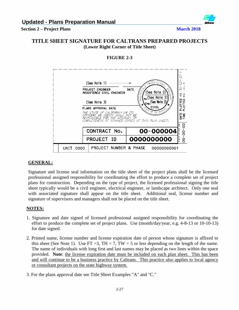
TITLE SHEET SIGNATURE FOR CALTRANS PREPARED PROJECTS (Lower Right Corner of Title Sheet)
FIGURE 2-3
GENERAL:
Signature and license seal information on the title sheet of the project plans shall be the licensed
professional assigned responsibility for coordinating the effort to produce a complete set of project
plans for construction. Depending on the type of project, the licensed professional signing the title
sheet typically would be a civil engineer, electrical engineer, or landscape architect. Only one seal
with associated signature shall appear on the title sheet. Additional seal, license number and
signature of supervisors and managers shall not be placed on the title sheet.
NOTES:
1. Signature and date signed of licensed professional assigned responsibility for coordinating the
effort to produce the complete set of project plans. Use (month/day/year, e.g. 4-8-13 or 10-10-13)
for date signed.
2. Printed name, license number and license expiration date of person whose signature is affixed to
this sheet (See Note 1). Use FT =3, TH = 7, TW = 5 or less depending on the length of the name.
The name of individuals with long first and last names may be placed as two lines within the space
provided. Note: the license expiration date must be included on each plan sheet. This has been
and will continue to be a business practice by Caltrans. This practice also applies to local agency
or consultant projects on the state highway system.
3. For the plans approval date see Title Sheet Examples "A" and "C."

Plans Preparation Manual (U.S. Customary Units)
Chapter 2 – Project Plans March 2018
2-28
TITLE SHEET SIGNATURE FOR A PROJECT PREPARED BY CONSULTANT
FOR CALTRANS OR A PROJECT PREPARED BY A LOCAL AGENCY (Lower Right Corner of Title Sheet)
FIGURE 2-4
GENERAL:
Signature and license seal information on the title sheet of the project plans shall be the licensed professional
assigned responsibility for coordinating the effort to produce the complete set of project plans for construction.
Depending on the type of project, the person signing the title sheet typically is a licensed civil engineer,
electrical engineer, or landscape architect. Only one signature and license seal shall appear on the title sheet.
The only other name, signature, professional license number and license expiration date (NO SEAL) on the
title sheet is for the Caltrans Design Oversight Approval (see Figure 2-7).
NOTES:
1. Signature and date signed of the licensed professional assigned responsibility for coordinating the effort to
produce the complete set of project plans. Use (month/day/year, e.g. 4-8-13 or 10-10-13) for date signed.
2. Name, license number and license expiration date of person whose signature is affixed to this sheet (See
Note 1). Use FT =3, TH = 7, TW = 5 or less depending on the length of the name. The name of individuals
with long first and last names may be placed as two lines within the space provided.
3. For the plans approval date see Title Sheet Examples "A" and "C."
4. Where a prime consultant develops the entire project for Caltrans, the name and address of the prime
consultant shall be placed in this location. Use FT =3, TH = 6, TW = 6.
5. Where the entire project is financed and prepared by a permittee or agency, the name and address of the
permittee or agency shall be placed in this location. Use FT =3, TH = 6, TW = 6.
6. Only the name and address of the permittee or agency or prime consultant, as applicable, responsible for the
project shall be shown. No logos, phone numbers or artwork.

Plans Preparation Manual (U.S. Customary Units)
Chapter 2 – Project Plans March 2018
2-29
TITLE SHEET SIGNATURE FOR A PROJECT PREPARED BY A
CONSULTANT FOR A PERMITEE OR LOCAL AGENCY (Lower Right Corner of Title Sheet)
FIGURE 2-5
GENERAL:
Signature and license seal information on the title sheet of the project plans shall be the licensed professional
assigned responsibility for coordinating the effort to produce the complete set of project plans for construction.
Depending on the type of project, the licensed professional signing the title sheet typically is a licensed civil
engineer, electrical engineer, or landscape architect. Only one signature and license seal shall appear on the
title sheet. The only other name, signature, professional license number and license expiration date (NO
SEAL) on the title sheet is for the Caltrans Design Oversight Approval (see Figure 2-7).
NOTES:
1. Signature and date signed of licensed professional assigned responsibility for coordinating the effort to
produce the complete set of project plans. Use (month/day/year, e.g. 4-8-13 or 10-10-13) for date signed.
2. Name, license number and license expiration date of licensed professional whose signature is affixed to this
sheet (See Note 1). Use FT =3, TH = 7, TW = 5 or less depending on the length of the name. The name of
individuals with long first and last names may be placed as two lines within the space provided.
3. For the plans approval date see Title Sheet Examples "A" and "C."
4. Where a prime consultant develops the entire project for a permittee or agency, the name and address of the
prime consultant shall be placed in this location. Use FT =3, TH = 6, TW = 6.
5. The name and address of permittee or agency that hired the prime consultant shall be placed in this location.
Use FT =3, TH = 6, TW = 6.
6. Only names and addresses of the permittee or agency or prime consultant responsible for the project shall be
shown. No logos, phone numbers or artwork.
Plans Preparation Manual (U.S. Customary Units)
Chapter 2 – Project Plans March 2018
2-30
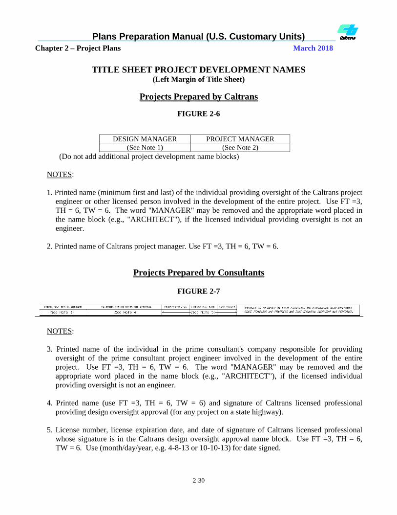
TITLE SHEET PROJECT DEVELOPMENT NAMES (Left Margin of Title Sheet)
Projects Prepared by Caltrans
FIGURE 2-6
DESIGN MANAGER PROJECT MANAGER
(See Note 1) (See Note 2)
(Do not add additional project development name blocks)
NOTES:
1. Printed name (minimum first and last) of the individual providing oversight of the Caltrans project
engineer or other licensed person involved in the development of the entire project. Use FT =3,
TH = 6, TW = 6. The word "MANAGER" may be removed and the appropriate word placed in
the name block (e.g., "ARCHITECT"), if the licensed individual providing oversight is not an
engineer.
2. Printed name of Caltrans project manager. Use FT =3, TH = 6, TW = 6.
Projects Prepared by Consultants
FIGURE 2-7
NOTES:
3. Printed name of the individual in the prime consultant's company responsible for providing
oversight of the prime consultant project engineer involved in the development of the entire
project. Use FT =3, TH = 6, TW = 6. The word "MANAGER" may be removed and the
appropriate word placed in the name block (e.g., "ARCHITECT"), if the licensed individual
providing oversight is not an engineer.
4. Printed name (use FT =3, TH = 6, TW = 6) and signature of Caltrans licensed professional
providing design oversight approval (for any project on a state highway).
5. License number, license expiration date, and date of signature of Caltrans licensed professional
whose signature is in the Caltrans design oversight approval name block. Use FT =3, TH = 6,
TW = 6. Use (month/day/year, e.g. 4-8-13 or 10-10-13) for date signed.

Plans Preparation Manual (U.S. Customary Units)
Chapter 2 – Project Plans March 2018
2-31
INDIVIDUAL PLAN SHEET SIGNATURE FOR PROJECTS
PREPARED BY CALTRANS (Upper Right Corner of Border Sheet)
FIGURE 2-8
GENERAL:
Only one seal and signature of the appropriate licensed professional in responsible charge for
developing the plan sheet shall appear on each individual plan sheet.
NOTES:
1. Signature and date signed of licensed professional in responsible charge for preparation of the
plan sheet. Use (month/day/year, e.g. 4-8-13 or 10-10-13) for date signed. NOTE: for a licensed
Landscape Architect see Figure 2-9a.
2. Name, license number and license expiration date of person whose signature is affixed to this
sheet (See Note 1). Use FT =3, TH = 7, TW = 5 or less depending on the length of the name.
The name of individuals with long first and last names may be placed as 2 lines within the space
provided.
3. For the plans approval date see Title Sheet Examples "A" and "C."

Plans Preparation Manual (U.S. Customary Units)
Chapter 2 – Project Plans March 2018
2-32
INDIVIDUAL PLAN SHEET SIGNATURE FOR A PROJECT PREPARED BY A
CONSULTANT FOR CALTRANS, OR A PROJECT PREPARED BY A LOCAL
AGENCY, OR A PROJECT PREPARED BY A CONSULTANT FOR A
PERMITEE OR LOCAL AGENCY (Upper Right Corner of Border Sheet)
FIGURE 2-9
GENERAL:
Only one seal and signature of the appropriate licensed professional in responsible charge of developing the
plan sheet shall appear on each individual plan sheet.
NOTES:
1. Signature and date signed of licensed professional in responsible charge for preparation of the plan sheet.
Use (month/day/year, e.g. 4-8-13 or 10-10-13) for date signed.
2. Name, license number and license expiration date of person whose signature is affixed to this sheet (See
Note 1). Use FT =3, TH = 7, TW = 5 or less depending on the length of the name. The name of
individuals with long first and last names may be placed as 2 lines within the space provided.
3. For the plans approval date see Title Sheet Examples "A" and "C."
4. Where the prime consultant or sub consultant prepares the plan sheet for Caltrans or a permittee or local
agency, the name and address of the one consultant responsible for the sheet shall be placed in this
location. Use FT =3, TH = 6, TW = 6.
5. The name and address of the permittee or local agency that hired the consultant shall be placed in this
location. Use FT =3, TH = 6, TW = 6. Not for the name of a second consultant. This space is reserved
for permittee or local agency use only.
6. Where the work shown on the plan sheet is financed and prepared by a permittee or agency, the name and
address of the permittee or agency shall be placed in this location. Use FT =3, TH = 6, TW = 6.
7. Only names and addresses of the local agency and consultant responsible for each specific sheet shall be
shown. No logos, phone numbers or artwork

Plans Preparation Manual (U.S. Customary Units)
Chapter 2 – Project Plans March 2018
2-33
LANDSCAPE TITLE SHEET OR INDIVIDUAL LANDSCAPE PLAN SHEET
SIGNATURE FOR A PROJECT PREPARED BY A CALTRANS, OR A
CONSULTANT FOR CALTRANS, OR A PROJECT PREPARED BY A LOCAL
AGENCY, OR A PROJECT PREPARED BY A CONSULTANT FOR A
PERMITEE OR LOCAL AGENCY (Lower Right Corner of Title Border Sheet)
or
(Upper Right Corner of Border Sheet)
FIGURE 2-9a
GENERAL:
Only one seal and signature of the appropriate licensed Landscape Architect in responsible charge
for developing the plan sheet shall appear on the title sheet or each individual plan sheet.
NOTES:
1. A second signature of the licensed Landscape Architect in responsible charge for preparation of
the plan sheet.
2. Signature, date of signature, license number, printed name and license renewal date of Landscape
Architect whose signature is affixed to this sheet. Use FT =3, TH = 5, TW = 5 and WT = 1 for
signature date and renewal date. Use FT = 3, TH = 3, TW = 3 and WT = 0 for printed name and
license number (arched above the signature within the seal).
3. For the plans approval date see Title Sheet Examples "A" and "C."
Plans Preparation Manual (U.S. Customary Units)
Chapter 2 – Project Plans March 2018
2-34
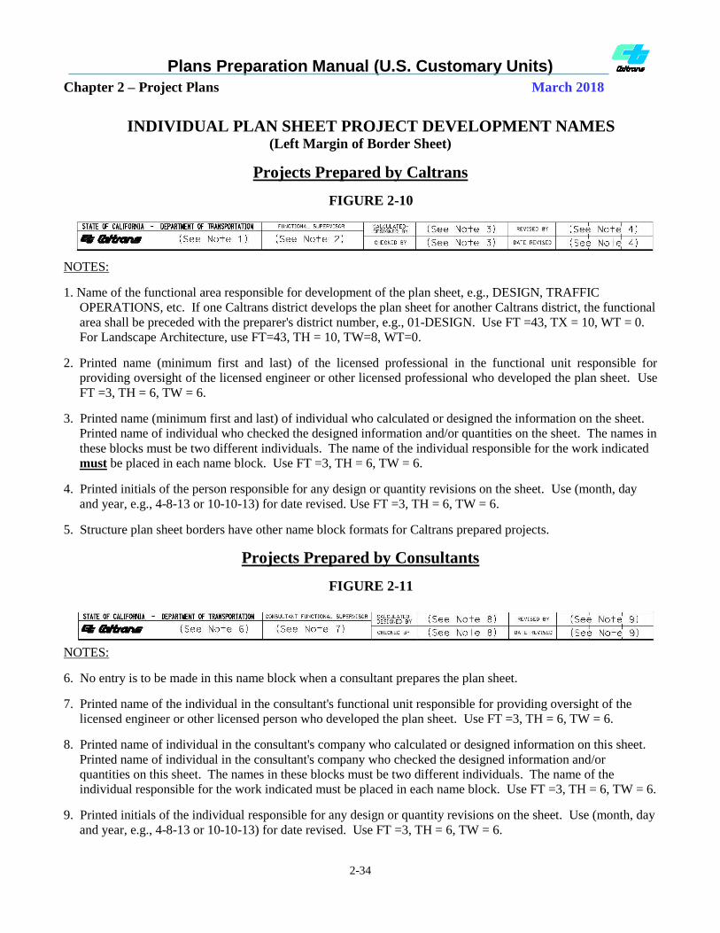
INDIVIDUAL PLAN SHEET PROJECT DEVELOPMENT NAMES (Left Margin of Border Sheet)
Projects Prepared by Caltrans
FIGURE 2-10
NOTES:
1. Name of the functional area responsible for development of the plan sheet, e.g., DESIGN, TRAFFIC
OPERATIONS, etc. If one Caltrans district develops the plan sheet for another Caltrans district, the functional
area shall be preceded with the preparer's district number, e.g., 01-DESIGN. Use FT =43, TX = 10, WT = 0.
For Landscape Architecture, use FT=43, TH = 10, TW=8, WT=0.
2. Printed name (minimum first and last) of the licensed professional in the functional unit responsible for
providing oversight of the licensed engineer or other licensed professional who developed the plan sheet. Use
FT =3, TH = 6, TW = 6.
3. Printed name (minimum first and last) of individual who calculated or designed the information on the sheet.
Printed name of individual who checked the designed information and/or quantities on the sheet. The names in
these blocks must be two different individuals. The name of the individual responsible for the work indicated
must be placed in each name block. Use FT =3, TH = 6, TW = 6.
4. Printed initials of the person responsible for any design or quantity revisions on the sheet. Use (month, day
and year, e.g., 4-8-13 or 10-10-13) for date revised. Use FT =3, TH = 6, TW = 6.
5. Structure plan sheet borders have other name block formats for Caltrans prepared projects.
Projects Prepared by Consultants
FIGURE 2-11
NOTES:
6. No entry is to be made in this name block when a consultant prepares the plan sheet.
7. Printed name of the individual in the consultant's functional unit responsible for providing oversight of the
licensed engineer or other licensed person who developed the plan sheet. Use FT =3, TH = 6, TW = 6.
8. Printed name of individual in the consultant's company who calculated or designed information on this sheet.
Printed name of individual in the consultant's company who checked the designed information and/or
quantities on this sheet. The names in these blocks must be two different individuals. The name of the
individual responsible for the work indicated must be placed in each name block. Use FT =3, TH = 6, TW = 6.
9. Printed initials of the individual responsible for any design or quantity revisions on the sheet. Use (month, day
and year, e.g., 4-8-13 or 10-10-13) for date revised. Use FT =3, TH = 6, TW = 6.

Plans Preparation Manual (U.S. Customary Units)
Chapter 2 – Project Plans March 2018
2-35
10. Structure plan sheet borders and seed files for consultant prepared projects are available at this web site:
http://www.dot.ca.gov/hq/oppd/cadd/rsc_files/webpage.htm

Plans Preparation Manual (U.S. Customary Units)
Chapter 2 – Project Plans March 2018
2-36
THIS PAGE INTENTIONALLY LEFT BLANK

Plans Preparation Manual (U.S. Customary Units)
Chapter 2 – Project Plans March 2018
2-37
2-1.7 Project Identification Block and County Abbreviations
Project Identification Block
The project identification block (see Figure 2-12) must contain these items specific to each project:
Caltrans District Number (two District Numbers on very rare occasions)
Standard abbreviation for county or counties where the project is located (see Table 2-1.6)
Route or routes where project construction is to take place
Post mile limits of construction (except for those specific projects described herein)
Individual sheet number
Project total number of sheets
The sheet number and total number of sheets are to be left blank for projects which are not AADD.
Division of Engineering Services-Office Engineer (DES-OE) will insert the sheet number and total
number of sheets. For AADD projects, the districts will include both sheet number and total number of
sheets.
FIGURE 2-12
PROJECT IDENTIFICATION BLOCK
(Upper Right Corner of each Border Sheet)
Dist COUNTY ROUTE POST MILES
TOTAL PROJECT
SHEET
No.
TOTAL
SHEETS
Project Case Designation Numbers
For the purpose of referencing instructions related to the development of each title sheet project
description and its associated project identification block, the various types of projects have been
assigned case designation numbers. These case identification numbers apply to both this section of the
manual and to the subsection titled, "Title Sheet Project Descriptions," in Section 2-2.2 of this manual.
Project Construction on One Route
Case 1A Project - One location on one route in one county with a continuous length of
construction that is 0.2 mile or greater
In the project identification block, use a slash between the associated post miles for begin and
end of construction. (In the title sheet project description use the "From…To…" format to
describe the location.)
Example:
Dist COUNTY ROUTE POST MILES
TOTAL PROJECT
SHEET
No.
TOTAL
SHEETS
07 LA 5 74.9/79.3

Plans Preparation Manual (U.S. Customary Units)
Chapter 2 – Project Plans March 2018
2-38
Project Construction on One Route (Continued)
Case 1B Project - One location on one route in more than one county with a continuous length
of construction that is 0.2 mile or greater
In the project identification block, list the counties in order of the direction of construction.
Use a comma between counties. A slash is used between the associated post miles for each
county and a comma is used between the two sets of post miles. The order of listing the post
miles is to match the order of listing the counties. (In the title sheet project description, use
the "From…To…" format to describe the location.)
Example:
Dist COUNTY ROUTE POST MILES
TOTAL PROJECT
SHEET
No.
TOTAL
SHEETS
04 SM, SF 1 R78.1/R78.2,
R0.0/R0.7
----------------------------------------------------------------------------------------------------------------------------- --------------------
Case 1C Project - Two locations on one route in one county with both locations having a length
of construction that is 0.2 mile or greater in length
In the project identification block, use a slash between the associated post miles for begin and
end of construction for each location and a comma between the two sets of post miles. (In
the title sheet project description, use the "From…To…" format to describe each location.)
Example:
Dist COUNTY ROUTE POST MILES
TOTAL PROJECT
SHEET
No.
TOTAL
SHEETS
07 LA 5 74.9/79.3, 81.2/83.5
----------------------------------------------------------------------------------------------------------------------------- --------------------
Case 1D Project - Two locations on one route in one county with one location 0.2 mile or
greater in length and one location less than 0.2 mile (spot location)
In the project identification block, use a slash between the associated post miles for begin and
end of construction for the location 0.2 mile or greater in length followed by a comma and a
single post mile to describe the spot location. (In the title sheet project description, describe
the location 0.2 mile or greater in length using the "From…To…" format and describe the
location less than 0.2 mile in length by using a spot location description "At…".)
Example:
Dist COUNTY ROUTE POST MILES
TOTAL PROJECT
SHEET
No.
TOTAL
SHEETS
07 LA 5 74.9/77.6, 78.9

Plans Preparation Manual (U.S. Customary Units)
Chapter 2 – Project Plans March 2018
2-39
Project Construction on One Route (Continued)
Case 1E Project - Two locations on one route in one county with individual lengths of
construction less than 0.2 mile (spot locations)
In the project identification block, use a single post mile to describe each location separated
by a comma. (In the title sheet project description, describe the two locations by using spot
location descriptions "At…" and "At…".)
Example:
Dist COUNTY ROUTE POST MILES
TOTAL PROJECT
SHEET
No.
TOTAL
SHEETS
06 Fre 99 43.9, 45.7
-------------------------------------------------------------------------------------------------------------------------
Case 1F Project - One location on one route in one county with an individual length of
construction less than 0.2 mile (spot location)
In the project identification block, use a single post mile to describe the location. (In the title
sheet project description, describe the location by using a spot location description "At…".)
Example:
Dist COUNTY ROUTE POST MILES
TOTAL PROJECT
SHEET
No.
TOTAL
SHEETS
01 Men 1 80.8
-------------------------------------------------------------------------------------------------------------------------
Case 1G Project - One or more locations in one county with all locations within a 0.6-mile
radius of the center of a route separation
In the project identification block, use a single post mile for each route to describe the
location (post miles at route separation). The order of listing the post miles is to match the
order of listing the routes. (In the title sheet project description, describe the location by
using a spot location description "At Route XX/XXX Separation.")
Example:
Dist COUNTY ROUTE POST MILES
TOTAL PROJECT
SHEET
No.
TOTAL
SHEETS
07 LA 5, 118 63.4, 18.3
Plans Preparation Manual (U.S. Customary Units)
Chapter 2 – Project Plans March 2018
2-40
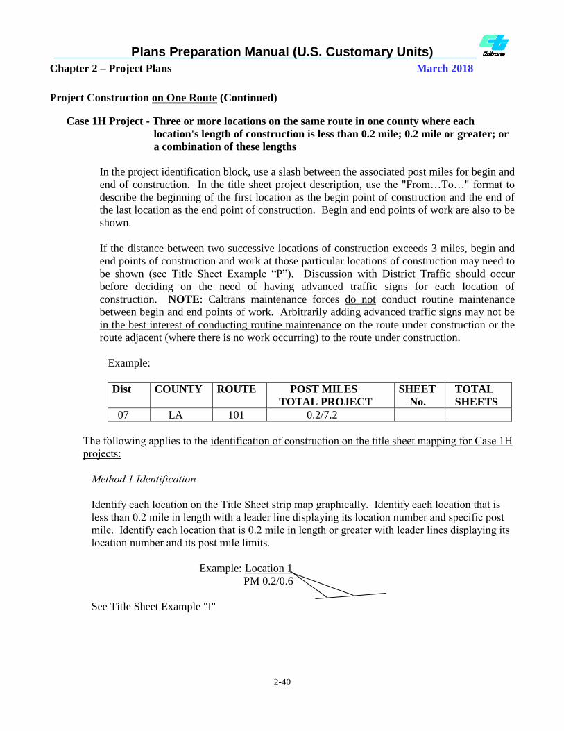
Project Construction on One Route (Continued)
Case 1H Project - Three or more locations on the same route in one county where each
location's length of construction is less than 0.2 mile; 0.2 mile or greater; or
a combination of these lengths
In the project identification block, use a slash between the associated post miles for begin and
end of construction. In the title sheet project description, use the "From…To…" format to
describe the beginning of the first location as the begin point of construction and the end of
the last location as the end point of construction. Begin and end points of work are also to be
shown.
If the distance between two successive locations of construction exceeds 3 miles, begin and
end points of construction and work at those particular locations of construction may need to
be shown (see Title Sheet Example “P”). Discussion with District Traffic should occur
before deciding on the need of having advanced traffic signs for each location of
construction. NOTE: Caltrans maintenance forces do not conduct routine maintenance
between begin and end points of work. Arbitrarily adding advanced traffic signs may not be
in the best interest of conducting routine maintenance on the route under construction or the
route adjacent (where there is no work occurring) to the route under construction.
Example:
Dist COUNTY ROUTE POST MILES
TOTAL PROJECT
SHEET
No.
TOTAL
SHEETS
07 LA 101 0.2/7.2
The following applies to the identification of construction on the title sheet mapping for Case 1H
projects:
Method 1 Identification
Identify each location on the Title Sheet strip map graphically. Identify each location that is
less than 0.2 mile in length with a leader line displaying its location number and specific post
mile. Identify each location that is 0.2 mile in length or greater with leader lines displaying its
location number and its post mile limits.
Example: Location 1
PM 0.2/0.6
See Title Sheet Example "I"
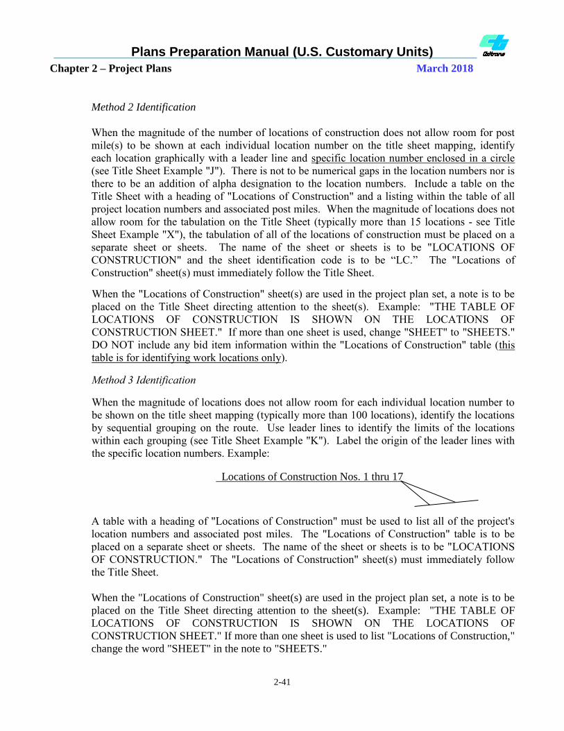
Plans Preparation Manual (U.S. Customary Units)
Chapter 2 – Project Plans March 2018
2-41
Method 2 Identification
When the magnitude of the number of locations of construction does not allow room for post
mile(s) to be shown at each individual location number on the title sheet mapping, identify
each location graphically with a leader line and specific location number enclosed in a circle
(see Title Sheet Example "J"). There is not to be numerical gaps in the location numbers nor is
there to be an addition of alpha designation to the location numbers. Include a table on the
Title Sheet with a heading of "Locations of Construction" and a listing within the table of all
project location numbers and associated post miles. When the magnitude of locations does not
allow room for the tabulation on the Title Sheet (typically more than 15 locations - see Title
Sheet Example "X"), the tabulation of all of the locations of construction must be placed on a
separate sheet or sheets. The name of the sheet or sheets is to be "LOCATIONS OF
CONSTRUCTION" and the sheet identification code is to be “LC.” The "Locations of
Construction" sheet(s) must immediately follow the Title Sheet.
When the "Locations of Construction" sheet(s) are used in the project plan set, a note is to be
placed on the Title Sheet directing attention to the sheet(s). Example: "THE TABLE OF
LOCATIONS OF CONSTRUCTION IS SHOWN ON THE LOCATIONS OF
CONSTRUCTION SHEET." If more than one sheet is used, change "SHEET" to "SHEETS."
DO NOT include any bid item information within the "Locations of Construction" table (this
table is for identifying work locations only).
Method 3 Identification
When the magnitude of locations does not allow room for each individual location number to
be shown on the title sheet mapping (typically more than 100 locations), identify the locations
by sequential grouping on the route. Use leader lines to identify the limits of the locations
within each grouping (see Title Sheet Example "K"). Label the origin of the leader lines with
the specific location numbers. Example:
Locations of Construction Nos. 1 thru 17
A table with a heading of "Locations of Construction" must be used to list all of the project's
location numbers and associated post miles. The "Locations of Construction" table is to be
placed on a separate sheet or sheets. The name of the sheet or sheets is to be "LOCATIONS
OF CONSTRUCTION." The "Locations of Construction" sheet(s) must immediately follow
the Title Sheet.
When the "Locations of Construction" sheet(s) are used in the project plan set, a note is to be
placed on the Title Sheet directing attention to the sheet(s). Example: "THE TABLE OF
LOCATIONS OF CONSTRUCTION IS SHOWN ON THE LOCATIONS OF
CONSTRUCTION SHEET." If more than one sheet is used to list "Locations of Construction,"
change the word "SHEET" in the note to "SHEETS."
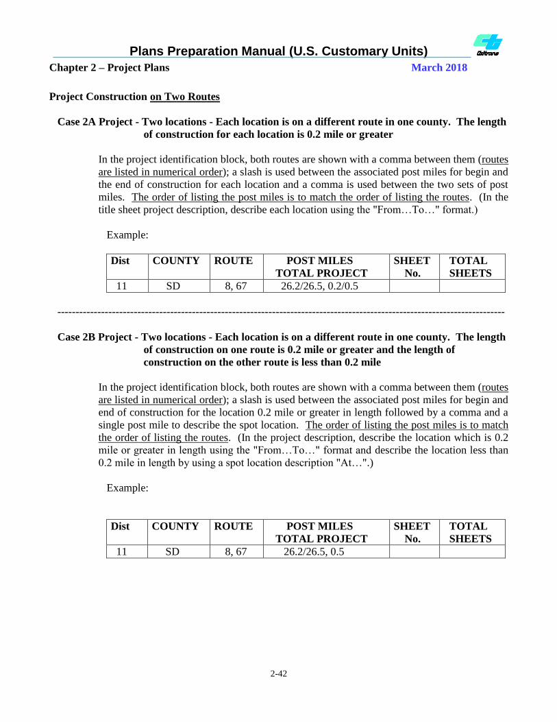
Plans Preparation Manual (U.S. Customary Units)
Chapter 2 – Project Plans March 2018
2-42
Project Construction on Two Routes
Case 2A Project - Two locations - Each location is on a different route in one county. The length
of construction for each location is 0.2 mile or greater
In the project identification block, both routes are shown with a comma between them (routes
are listed in numerical order); a slash is used between the associated post miles for begin and
the end of construction for each location and a comma is used between the two sets of post
miles. The order of listing the post miles is to match the order of listing the routes. (In the
title sheet project description, describe each location using the "From…To…" format.)
Example:
Dist COUNTY ROUTE POST MILES
TOTAL PROJECT
SHEET
No.
TOTAL
SHEETS
11 SD 8, 67 26.2/26.5, 0.2/0.5
---------------------------------------------------------------------------------------------------------------------------
Case 2B Project - Two locations - Each location is on a different route in one county. The length
of construction on one route is 0.2 mile or greater and the length of
construction on the other route is less than 0.2 mile
In the project identification block, both routes are shown with a comma between them (routes
are listed in numerical order); a slash is used between the associated post miles for begin and
end of construction for the location 0.2 mile or greater in length followed by a comma and a
single post mile to describe the spot location. The order of listing the post miles is to match
the order of listing the routes. (In the project description, describe the location which is 0.2
mile or greater in length using the "From…To…" format and describe the location less than
0.2 mile in length by using a spot location description "At…".)
Example:
Dist COUNTY ROUTE POST MILES
TOTAL PROJECT
SHEET
No.
TOTAL
SHEETS
11 SD 8, 67 26.2/26.5, 0.5

Plans Preparation Manual (U.S. Customary Units)
Chapter 2 – Project Plans March 2018
2-43
Project Construction on Two Routes (Continued)
Case 2C Project - Two locations - Each location is on a different route in one county. Each
construction location is less than 0.2 mile in length
In the project identification block, both routes are shown with a comma between them and a
single post mile is used to describe each location separated by a comma. Routes are listed in
numerical order. The order of listing the post miles is to match the order of listing the routes.
(In the project description, describe each location using a spot location description "At…".)
Example:
Dist COUNTY ROUTE POST MILES
TOTAL PROJECT
SHEET
No.
TOTAL
SHEETS
11 SD 8, 67 26.5, 0.5
-------------------------------------------------------------------------------------------------------------------------
Case 2D Project - Two locations - Each location is on a different route. Each route is in a
different county. The length of construction for each location is 0.2 mile or
greater
In the project identification block, list the routes in numerical order and list counties to match
associated routes. Use a comma between counties. A slash is used between the associated
post miles for each route and a comma is used between the two sets of post miles (post miles
for begin and end of construction for each location). The order of listing the post miles is to
match the order of listing the routes. (In the title sheet project description, describe each
location using the "From…To…" format.)
Example:
Dist COUNTY ROUTE POST MILES
TOTAL PROJECT
SHEET
No.
TOTAL
SHEETS
08 SBd, Riv 18,71 11.3/12.1, 0.0/R3.4

Plans Preparation Manual (U.S. Customary Units)
Chapter 2 – Project Plans March 2018
2-44
Case 2E Project - Two locations - Each location is on a different route. Each route is in a
different county. The length of construction on one route is 0.2 mile or
greater and the length of construction on the other route is less than 0.2 mile
In the project identification block, list the routes in numerical order (use a comma between
route numbers). List the counties to match their associated routes. Use a comma between
counties. Use a slash between the associated post miles for begin and end of construction for
the location 0.2 mile or greater in length followed by a comma and a single post mile to
describe the spot location. The order of listing the post miles is to match the order of listing
the routes.
(In the project description, describe the location which is 0.2 mile or greater in length using
the "From…To…" format and describe the location less than 0.2 mile in length by using a
spot location description "At …".)
Example:
Dist COUNTY ROUTE POST MILES
TOTAL PROJECT
SHEET
No.
TOTAL
SHEETS
08 SBd, Riv 18,71 11.3/12.1, R3.4
--------------------------------------------------------------------------------------------------------------------------
Case 2F Project - Two locations - Each location is on a different route. Each route is in a
different county. Each construction location is less than 0.2 mile in length
In the project identification block list the routes in numerical order (use a comma between
route numbers). List the counties to match their associated routes. Use a comma between
counties. The order of listing the post miles is to match the order of listing the routes. (In the
project description, describe each location using a spot location description "At…".)
Example:
Dist COUNTY ROUTE POST MILES
TOTAL PROJECT
SHEET
No.
TOTAL
SHEETS
08 SBd, Riv 18,71 11.3, R3.4

Plans Preparation Manual (U.S. Customary Units)
Chapter 2 – Project Plans March 2018
2-45
Project Construction is:
At three or more locations on two or more routes
At three or more locations in two or more counties
The following applies to the project identification block for these projects:
Counties, in which the project is located, are listed in alphabetical order with a comma between
them. The order of listing the counties may not always match the order of listing of the routes.
When the number of counties exceeds six, see instructions herein.
Routes are listed in numerical order. When the number of routes exceeds six, see instructions
herein.
Up to six counties or routes can be shown in the project identification block.
No post miles are to be listed in the "Post Mile Block." "Var" is to be used in the "Post Miles
Block." "Var" represents the various post miles of the different routes.
Example I.D. Block for project in two counties on five routes:
Dist COUNTY ROUTE POST MILES
TOTAL PROJECT
SHEET
No.
TOTAL
SHEETS
08 Riv, SBd 18, 71, 138,
173, 189
Var
Number of counties exceeds six:
If a project is in more counties than can be listed in the county identification block (more than six),
then list the first five counties alphabetically and include "etc." at the end of the county listings in the
county identification block. Use lowercase and italic text for "etc.", see example below. Do not use
the "Var" designation in the identification block for "County." The Title Sheet project description
must include the listing of all counties involved. Do not use abbreviations for the county names in the
title sheet project description. The special provisions for the project must list all counties as well. If
there isn’t enough room to list the six counties in the identification block, see Title Sheet Example “X”
for acceptable text size variation.
Example I.D. Block for project with more than six counties on two routes:
Dist COUNTY ROUTE POST MILES
TOTAL PROJECT
SHEET
No.
TOTAL
SHEETS
03 But, ED, Nev,
Pla, Sut, etc.
49, 99 Var
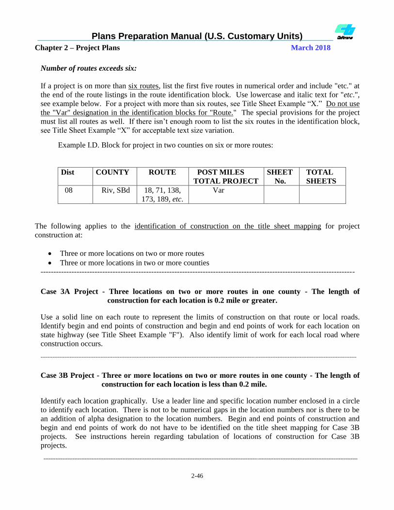
Plans Preparation Manual (U.S. Customary Units)
Chapter 2 – Project Plans March 2018
2-46
Number of routes exceeds six:
If a project is on more than six routes, list the first five routes in numerical order and include "etc." at
the end of the route listings in the route identification block. Use lowercase and italic text for "etc.",
see example below. For a project with more than six routes, see Title Sheet Example “X.” Do not use
the "Var" designation in the identification blocks for "Route." The special provisions for the project
must list all routes as well. If there isn’t enough room to list the six routes in the identification block,
see Title Sheet Example “X” for acceptable text size variation.
Example I.D. Block for project in two counties on six or more routes:
Dist COUNTY ROUTE POST MILES
TOTAL PROJECT
SHEET
No.
TOTAL
SHEETS
08 Riv, SBd 18, 71, 138,
173, 189, etc.
Var
The following applies to the identification of construction on the title sheet mapping for project
construction at:
Three or more locations on two or more routes
Three or more locations in two or more counties
--------------------------------------------------------------------------------------------------------------------------
Case 3A Project - Three locations on two or more routes in one county - The length of
construction for each location is 0.2 mile or greater.
Use a solid line on each route to represent the limits of construction on that route or local roads.
Identify begin and end points of construction and begin and end points of work for each location on
state highway (see Title Sheet Example "F"). Also identify limit of work for each local road where
construction occurs.
----------------------------------------------------------------------------------------------------------------------------------------------------------------------------------------
Case 3B Project - Three or more locations on two or more routes in one county - The length of
construction for each location is less than 0.2 mile.
Identify each location graphically. Use a leader line and specific location number enclosed in a circle
to identify each location. There is not to be numerical gaps in the location numbers nor is there to be
an addition of alpha designation to the location numbers. Begin and end points of construction and
begin and end points of work do not have to be identified on the title sheet mapping for Case 3B
projects. See instructions herein regarding tabulation of locations of construction for Case 3B
projects.
---------------------------------------------------------------------------------------------------------------------------------------------------------------------------------------

Plans Preparation Manual (U.S. Customary Units)
Chapter 2 – Project Plans March 2018
2-47
Case 3C Project - Three or more locations on two or more routes in two or more counties - Each
location's length of construction is less than 0.2 mile, 0.2 mile or greater, or a
combination of these lengths
If there is sufficient space available on the title sheet mapping, identify each location graphically. Use
a leader line and specific location number enclosed in a circle to identify each location. There is not to
be numerical gaps in the location numbers nor is there to be an addition of alpha designation to the
location numbers. See Title Sheet Example "J."
Begin and end points of construction and begin and end points of work are not identified on the title
sheet mapping for Case 3C projects. See instructions herein regarding tabulation of locations of
construction for Case 3C projects.
----------------------------------------------------------------------------------------------------------------------------------------------------------------------------------------
Case 3D Projects - The magnitude of locations (typically more than 100 locations) does not allow
room for each individual location number to be shown on the title sheet
mapping as in a Case 3C project. Each location's length of construction is
less than 0.2 mile, 0.2 mile or greater, or a combination of these lengths
Identify the locations by sequential grouping on each route. Do not repeat construction location
numbers from route to route. Use leader lines to identify the locations within each grouping. Label
the origin of the leader lines with the specific route and locations of construction numbers.
Examples of sequential grouping:
Route 18 - Locations of
Construction Nos. 1 thru 17
Route 71 - Locations of
Construction Nos. 18 thru 32
See Title Sheet Example "K"
Begin and end points of construction and begin and end points of work are not identified on the title
sheet mapping for Case 3D projects. See instructions herein regarding tabulation of locations of
construction for Case 3D projects.
--------------------------------------------------------------------------------------------------------------------------

Plans Preparation Manual (U.S. Customary Units)
Chapter 2 – Project Plans March 2018
2-48
Case 3B, Case 3C, and Case 3D Projects- Tabulation of Locations of Construction
When the locations of construction are shown individually (Case 3B and Case 3C) or by sequential
grouping (Case 3D) on the Title Sheet mapping, a table with a heading of "Locations of Construction"
must be included in the project plans. The table must list each location of construction (whether it is a
spot location or “To…From” format) by location number, county, route, and post mile(s).
The "Locations of Construction" table is to be placed on the Title Sheet when sufficient space is
available. When the magnitude of locations does not allow room for the table on the Title Sheet
(typically more than 15 locations), the tabulation of all of the locations of construction must be placed
on a separate sheet or sheets. The name of the sheet or sheets is to be "LOCATIONS OF
CONSTRUCTION." Since this table is part of the title sheet (and bid items ARE NOT to be included
on the title sheet) DO NOT include bid items with this table.
The "Locations of Construction" sheet(s) must immediately follow the Title Sheet. When the
"Locations of Construction" sheet(s) are used in the project plan set, a note is to be placed on the Title
Sheet directing attention to the sheet(s). Example: "THE TABLE OF LOCATIONS OF
CONSTRUCTION IS SHOWN ON THE LOCATIONS OF CONSTRUCTION SHEET." If more
than one sheet is used, change "SHEET" to "SHEETS."
--------------------------------------------------------------------------------------------------------------------------
Case 4 Project - The locations of construction are on a large number of routes and sufficient
space is not available on the Title Sheet mapping to identify the locations of
project construction by use of individual location of construction numbers
(Case 3B or Case 3C) or by numbered sequential grouping of locations of
construction for each route (Case 3D)
The following applies to Case 4 projects:
Use a solid line on each route to represent the limits of the locations of construction on that
route. Do not show begin and end points of construction and begin and end points of work.
Use an alpha designation enclosed in a circle and a leader line pointing to the solid line used on
each route to indicate that there are locations of construction on that route.
Include a table on the Title Sheet that lists the alpha designations and their corresponding
locations of construction for each route. Use the title "LOCATIONS SUMMARY" for this table.
This should avoid any confusion between the table on the title sheet and the required listing of
individual locations on the table titled "Locations of Construction" on the "Locations of
Construction" sheet(s). The "Locations of Construction" sheet(s) must immediately follow the
Title Sheet.
The "Locations of Construction" table on the "Locations of Construction" sheet(s) must list (at a
minimum) locations of construction by each individual location number, county, route, and post
mile(s). The "Locations of Construction" sheet(s) must immediately follow the Title Sheet.
Include a note on the Title Sheet directing attention to the locations of construction sheet(s).
Example: "THE TABLE OF LOCATIONS OF CONSTRUCTION IS SHOWN ON THE
LOCATIONS OF CONSTRUCTION SHEET." If more than one sheet is used to list "Locations
of Construction," change the word "SHEET" in the note to "SHEETS."

Plans Preparation Manual (U.S. Customary Units)
Chapter 2 – Project Plans March 2018
2-49
THIS PAGE INTENTIONALLY LEFT BLANK
Plans Preparation Manual (U.S. Customary Units)
Chapter 2 – Project Plans March 2018
2-50
THIS PAGE INTENTIONALLY LEFT BLANK

Plans Preparation Manual (U.S. Customary Units)
Chapter 2 – Project Plans March 2018
2-51
TABLE 2-1.6
COUNTY ABBREVIATIONS
COUNTY
COUNTY
ABBREVIATION Alameda Ala
Alpine Alp
Amador Ama
Butte But
Calaveras Cal
Colusa Col
Contra Costa CC
Del Norte DN
El Dorado ED
Fresno Fre
Glenn Gle
Humboldt Hum
Imperial Imp
Inyo Iny
Kern Ker
Kings Kin
Lake Lak
Lassen Las
Los Angeles LA
Madera Mad
Marin Mrn
Mariposa Mpa
Mendocino Men
Merced Mer
Modoc Mod
Mono Mno
Monterey Mon
Napa Nap
Nevada Nev
COUNTY
COUNTY
ABBREVIATION Orange Ora
Placer Pla
Plumas Plu
Riverside Riv
Sacramento Sac
San Benito SBt
San Bernardino SBd
San Diego SD
San Francisco SF
San Joaquin SJ
San Luis Obispo SLO
San Mateo SM
Santa Barbara SB
Santa Clara SCl
Santa Cruz SCr
Shasta Sha
Sierra Sie
Siskiyou Sis
Solano Sol
Sonoma Son
Stanislaus Sta
Sutter Sut
Tehama Teh
Trinity Tri
Tulare Tul
Tuolumne Tuo
Ventura Ven
Yolo Yol
Yuba Yub
Use the above list for the correct abbreviation of each county. Use upper and lower case lettering as
shown.

Plans Preparation Manual (U.S. Customary Units)
Chapter 2 – Project Plans March 2018
2-52
2-1.8 Sheet Identification Codes, Sheet
Names, and Plan Order
A coding system maintains sheet order during
the design and construction of the project. The
larger the project, the more important a coding
system becomes because it facilitates sorting out
specific data and is used extensively for cross-
referencing.
Coding consists of identifying each sheet of
plans by the appropriate sheet identification
code letter(s) and by numbering those sheets
consecutively, e.g., L-1, L-2, L-3, etc. The
codes such as L-1, D-1, etc., identify individual
project plan sheets for cross-referencing. The
title sheet does not require a sheet identification
code.
The sheet name such as layout, drainage plan,
etc., identifies the plan for indexing.
Refer to Section 2.1 of the CADD Manual for
additional instructions for the sheet naming
convention (sheet identification codes, sheet
names, print sequence codes (part of the DGN
file name), and order of sheets in a project plan
set).
The project plan sheet name and sheet
identification code is required on every sheet,
except the title sheet. They are to be placed
inside the sheet border at the lower right-hand
corner of each sheet.
When Office of Structure Design prepared plans
(e.g. sign structure, retaining wall, sound wall,
etc.) are included in the roadway portion of the
plans, the sheet name, sheet identification code,
print sequence code and file name must be those
listed for roadway plans. Office of Structure
Design may use their border sheet for such
plans. The project plan sheet name, sheet
identification code and any appropriate modifier
shall be the only sheet identification shown.
Where the project consists of work at various
locations, the work location number unique to
that sheet is to be shown in the lower right-hand
corner under the sheet name (as a modifier). A
modifier is also to be included on the Stage
Construction sheets identifying which stage or
sequence of work. Any modifier used is not to
be considered part of the sheet name.
The official project description, as it appears on
the title sheet, is not to be repeated on individual
plan sheets. The project description shall appear
only on the title sheet of the project set of plans.
Where more than one type of work is being
shown on an individual sheet, the combined
sheet name shall follow the plan sheet name
order in Section 2.1 of the CADD Manual
(example: "Pavement Delineation and Sign
Plan"). The sheet identification code for a plan
sheet with more than one type of work shown is
to be the code letter for the first type of work
shown in the plan sheet name (example: "PD"
for Pavement Delineation and Sign Plan). One
exception; when contour grading and drainage
information is combined, use the drainage sheet
identification code. Combining types of work
on an individual plan view sheet should be
limited to two types of work, with the exception
of layout sheets. The layout sheet may include
all types of work, depending on the complexity
of the project. Regardless of the various types
of work included on the layout sheet, the sheet
name is to be "Layout" and the sheet
identification codes are to be L-1, L-2, L-3, etc.
The sheet name for an Electrical Systems plan is
handled differently than the other plan sheets in
the project. Various individual bid items may
appear on the layout, drainage, signing, etc. plan
sheets. Whereas, Electrical Systems work is
usually paid for on a lump sum basis. The plan
sheet name is to be the same as the bid item on
the Bid Item List. The sheet name for an
Electrical Systems plan is the lump sum bid
item that appears in the bid item list. The plan

Plans Preparation Manual (U.S. Customary Units)
Chapter 2 – Project Plans March 2018
2-53
sheet can contain various materials and
components, but it is paid for by the name of the
plan sheet. Do not use the non pay symbol (N)
for components of the lump sum bid item. For
further information on Electrical Systems plans
see Section 2-2.23 of this manual.
Showing Design Information on Multiple
Plan View Sheets.
Layout sheets provide much of the background
(base topographic and roadbed information) for
all other plan view sheets (e.g. drainage,
pavement delineation, utilities, signing,
electrical systems, etc.). The statement
"APPROVED FOR .......... WORK ONLY" is
needed to clarify that the "other" plan view
sheets (e.g. drainage, pavement delineation,
signing, electrical systems, etc.) are only to be
utilized for the specific work approved on that
specific sheet. The statement above is not to be
placed on the layout sheet as most all bid items
can be shown on the layout sheet if space
allows. The statement "APPROVED FOR
.......... WORK ONLY" is not to be placed on
profile, detail or quantity sheets (since there
usually isn't "plan view" background
information shown on these sheets).
The statement for utility plan sheets is slightly
different than all other plan view sheets. The
statement to be used is "THIS PLAN TO BE
USED FOR UTILITY INFORMATION ONLY."
The word "APPROVED" is not included in the
statement so that it will not imply that an
exception to the utility policy had already been
granted. NOTE: do not confuse the above
statement with the two standard Caltrans utility
notes that might also appear on the plans.
When there is sufficient justification to vary
from the statutory requirements of providing all
utility information on the plans, such an
exception must first be approved by HQ
Division of Design. Once a variance is
approved by HQ Division of Design, then one
of the two standard Caltrans utilities notes can
be placed on the plans (see Section 2-2.13 for
the exact wording of the notes).
Discovery of undisclosed subsurface facilities
during construction can have a major impact to
the cost and schedule of completing any project.
Thus all utilities owned by others must be
shown on the “Utility Plans.” Subsurface
facilities owned by Caltrans must either be
shown on the utility plans or the Electrical
Systems plans. This will depend on the type of
subsurface facility, the size and type of project
and the most appropriate individual responsible
for the depiction of the subsurface facilities on
the project plans he/she is responsible for.
Existing Caltrans drainage facilities are to be
shown on the drainage plans (or layouts on a
small project). Utilities or subsurface facilities
may also be shown on other plan view sheets for
reference purposes only when these facilities are
in close proximity to identified work in the
project. Some Caltrans owned electrical
subsurface facilities may be shown on the
electrical systems plan sheets.
Design information identified as a bid item
should only be shown on one plan view type
sheet. If there is a need to show the bid item on
another plan view sheet for reference purposes
only, then it must not be identified (labeled) as a
bid item. It must be clear to the
bidder/contractor, for estimating and payment
purposes, on what plan sheet a bid item is paid
for (so an item doesn't get missed or counted
twice). Example: an irrigation crossover paid
for on the layout sheet, is also necessary to show
on the irrigation plan sheet, in order to show
where and how the irrigation system connects to
the crossover. In this example, the crossover on
the irrigation plan sheet may either be dropped
out or the weight of the line reduced to avoid
confusion.

Plans Preparation Manual (U.S. Customary Units)
Chapter 2 – Project Plans March 2018
2-54
2-1.9 Project Plan Submittals
The plans portion of the PS&E submittal sent to
DES-OE or any district Office Engineer for
AADD projects, are to be electronic files
consisting of a DGN and Iparm for each project
plan sheet. Use the appropriate "PS&E CADD
Submittal Form" and a "Project Plan Review
Checklist" (contact district Office Engineer to
obtain the form and checklist). Fill in all the
information on both forms completely and
accurately to process the project in a timely
manner.
Prints of the electronically transmitted CADD
files are not required as part of the PS&E
submittal unless requested by district Office
Engineer.
The regional center or each district, not within a
regional center, is to submit the roadway portion
of the project plans to DES-OE, for all non
AADD projects, using the above-specified
procedures. Roadway plans prepared by local
agencies or consultants must be sent to the
appropriate regional center or district for final
processing.
Office of Structure Design is to submit their
portion of the project plans (DGN files and
Iparms) to DES-OE, for all non AADD projects,
following the same procedures specified above.
For all AADD projects, the Office of Structure
Design will send the DGN files and Iparms to
each district for final processing. Structure
plans prepared by local agencies or consultants
must first be sent to Office of Structure Design
for technical review before the final processing
by the district.
Office of Transportation Architecture and The
Office of Electrical, Mechanical, Water and
Wastewater (TAEMWW) is to submit their
portion of the project plans (DGN files and
Iparms) to DES-OE, for all non AADD projects,
following the same procedures specified above.
For all AADD projects, TAEMWW will send
the DGN files and Iparms to each district for
final processing. Building plans prepared by
local agencies or consultants must first be sent
to TAEMWW for technical review before the
final processing by the district.
Plans Preparation Manual (U.S. Customary Units)
Chapter 2 – Project Plans March 2018
2-55
2-1.10 Project Plan File Formats
Standard Acceptable File Format
Caltrans only accepts 100 percent electronic
submittals. The standard file format for all
submissions of plans is a MicroStation design
file or DGN.
The following variations, with prior written
approval at approximately 60 percent
completion from the Division of Design, Office
of CADD and Engineering GIS Support, will be
considered for PS&E submittal, under these
specific circumstances:
DGN format files with imbedded or imported
raster data (aerial photographs or digital
pictures). Raster data should be limited to
detail sheets that require enhancing or
emphasizing of a detail or a unique location
(i.e. toll plaza at the San Francisco/Oakland
Bay Bridge) that the contractor might need to
see. The need for imported raster data should
be based on an engineering need, not for
aesthetics or a location identification need.
Project plans should first and foremost be
engineered plans not photogrammetric plans.
Aerial photographs were designed for
preliminary plans not final project plans. If
aerial mapping is needed for identifying
specific locations, plan sheets have been
established to handle the raster data. These
sheets are called "Aerial Identification" and
follow the "Key Map and Line Designation"
sheets. Raster data is not be used as
background for other plan sheets such as
layouts, drainage, utilities, pavement
delineation, etc.
Tiff or tagged image file format are acceptable
where legacy plans are being considered for
submission as part of a new CADD submittal.
Legacy plan sheets, such as existing log of test
boring and as-built data of existing structure
or roadway plans for reference or location
purposes, which are not available as electronic
files, may be scanned into raster (Tiff) format
and submitted for purposes of establishing a
100 percent electronic PS&E submittal. This
is a single, complete plan sheet with borders
intact, submitted as a tiff raster image. The
legacy sheet is to be scanned, sized (cropped),
de-speckled and de-skewed before submittal.
The preferred size of the finished Tiff plot is
22 inches x 34 inches and for special
circumstances the maximum allowable size is
23 inches x 35 inches. These files will be
raster edited.
Unacceptable Formats:
Hard Copy Originals
Reference Files (neither vector nor raster)
Cadd Generated Raster - Any file that was
created as a DGN file, but converted to raster
for convenience or expediency, will not be
accepted for PS&E Submittal.
Models- (submittals must be only one DGN
file for each project plan sheet.) Design
models containing multiple sheet models are
not acceptable.
AutoCad Files - Files started with AutoCad
(.dwg or .dxf) must be converted into a
MicroStation file (DGN) under the direction
of the engineer of record.
For additional information regarding project
plan formats, see Section 4.1 of the CADD
User's Manual.

Plans Preparation Manual (U.S. Customary Units)
Chapter 2 – Project Plans March 2018
2-56
THIS PAGE INTENTIONALLY LEFT BLANK