planning and installation instructions combisteamer (electric)
TRANSCRIPT

Planning and installation instructions
Combisteamer (electric)
SizeType no.Version
605ESC63XXXXSpaceSaver
610ESC60XXXXSpaceSaver PLUS
*FM07-185C* en-US
Space$aver™ Global Foodservice Solutions
3061
77--
-0A
IAE
-- /
14.1
2.20
09 /
TAG
-MaB
r

Planning and installation instructions
Space$aver™

5Planning ..............................................................15Standards and regulations ............................................1.15Ensure conformity with standards ............................................1.1.15Water ........................................................................................1.1.25Waste water .............................................................................1.1.36Electricity ..................................................................................1.1.46Room air ..................................................................................1.1.56Safety .......................................................................................1.1.67Food hygiene ...........................................................................1.1.78Relevant laws, institutions and authorities ...............................1.1.8
8Package dimensions and weights ................................1.2
9Weight ..............................................................................1.3
9Scale drawings ...............................................................1.49Abbreviations, installation dimensions .....................................1.4.1
10Installation dimensions .............................................................1.4.211Unit dimensions .......................................................................1.4.3
13Specifications, water ......................................................1.513Specifications, soft water .........................................................1.5.113Specifications, hard water ........................................................1.5.213Specifications, waste water ......................................................1.5.3
13Specifications, power supply ........................................1.6
15Heat loss .........................................................................1.7
15Ambient atmosphere and noise level ...........................1.8
16Transport .............................................................216Transporting the unit ......................................................2.1
17Installation ..........................................................317Installation information ..................................................3.1
18Mounting the suspension frame in the base frame .....3.2
20Installing tabletop units .................................................3.3
20Setting up with a stacking kit ........................................3.4
22Electricity ............................................................422Cable requirements ........................................................4.1
22Description of the terminal strip ...................................4.2
23Connecting the power supply .......................................4.324Three-phase power connection ................................................4.3.1
3Planning and installation instructionsGlobal Foodservice Solutions
ContentsSpace$aver™

24Single-phase power connection (only SpaceSaver) ...................4.3.2
26RS485/RS422 interface .....................................................4.4
26Connect performance optimization system (LOA) .........4.5
28Water ......................................................................528Water supply ......................................................................5.129Information about the soft water supply ......................................5.1.130Information about the hard water supply ....................................5.1.230Fitting the T-piece (accessory) ....................................................5.1.3
32Waste water connection ...................................................5.2
33Air outlet connection ............................................633Installation under an extraction hood .............................6.1
33Connection to an air outlet duct ......................................6.2
Global Foodservice SolutionsPlanning and installation instructions4
Space$aver™Contents

1 Planning1.1 Standards and regulations
1.1.1 Ensure conformity with standards
→ Ensure that your plans conform to the standards and regulationsapplying at the installation location.
NOTICEThe following overviews assist with orientation. They make no claimto be complete.
1.1.2 Water
DescriptionRelates toStandard
Drinking water protection, pre-servation of the drinking waterquality
Drinking water supplyDIN 1988-4
Table 1: Standards/regulations relevant to water
1.1.3 Waste water
DescriptionRelates toStandard
Additional specifications toDIN EN 752 andDIN EN 12056: Drainage sys-tems on private ground
Waste water qualityDIN 1986-100
Table 2: Standards/regulations relevant to waste water
5Planning and installation instructionsGlobal Foodservice Solutions
PlanningSpace$aver™

1.1.4 Electricity
DescriptionRelates toStandard
Provisions for the erection ofhigh-voltage current systemswith nominal voltages up to1000 V
Requirements for electroniccomponents
DIN VDE0100 ff.
Erection of low-voltage systemspart 5-54: Selection and erectionof electrical equipment – Earth-ing arrangements, protectiveconductors and protective poten-tial equalisation conductors
Potential equalisationDIN VDE0100-540
Erection of low-voltage systemspart 4-43: Protection for safety– Protection against overcurrent
Potential equalisation of thelocation
DIN VDE0100-430
Table 3: Standards/regulations relevant to electricity
1.1.5 Room air
DescriptionRelates toStandard
Ventilation equipment for kit-chen, basis for planning theventilation of commercial kit-chens as well as for calculatingthe size and construction ofventilation systems. It appliesin connection with the completereference work of DIN 1946.
Priority circuit room ventilationsystem
VDI 2052
General conditions for workingenvironments in kitchens withregard to the planning of kit-chen ventilation systems.
Emissions and comfortASR 5
Table 4: Standards/regulations relevant to room air
1.1.6 Safety
DescriptionRelates toStandard
Safety regulations for kitchens,kitchen safety equipment (fireextinguishers...)
Hazards in kitchens (formerlyZH 1/37)
BGR 111
Table 5: Standards/regulations relevant to safety
Global Foodservice SolutionsPlanning and installation instructions6
Space$aver™Planning

1.1.7 Food hygiene
DescriptionRelates toStandard
Regulation about food hygieneDocumentation of heatingtemperatures according toHACCP principles
Regulation(EG) Nr.852/2004
Table 6: Standards/regulations relevant to hygiene
7Planning and installation instructionsGlobal Foodservice Solutions
PlanningSpace$aver™

1.1.8 Relevant laws, institutions and authorities
Name of the institute/author-ity
Relates toStandard
Regional gas or energy suppli-er (GVU) or network operator
Gas supply
Installation of the unit
TAB (TechnicalConnectionConditions)GAS (LowPressure GasSupply (NDAV))
Building inspection authoritiesGas supply
Installation of the unit
BauO (BuildingRegulations);LBO (RegionalBuilding Regula-tions)
Trading standards officeInstallation of the unitGewO (Trade,Commerce andIndustry regula-tions)
Responsible district chim-ney/heating inspector
Gas supply
Installation of the unit, emis-sions
BauO (BuildingRegulations);FeuVo (Ordin-ance on FiringInstallations),BISchV (Feder-al EmissionControl Ordin-ance)
Water/waste water associationor authority
Installation of the unit
Water/waste water connections
AbwV (WasteWater Ordin-ance)
ATV informa-tion sheets (As-sociation ofWaste WaterTechnicians)
Technical connection condi-tions for connecting to the lowvoltage mains network, require-ments applying to the installa-tion location
Mains network operators,power suppliers
Installation of the unit
Mains connection
TAB (TechnicalConnectionConditions)POWER (NAV- Ordinance onLow-VoltageConnections)
Table 7: Relevant laws, institutions, authorities
1.2 Package dimensions and weights
NOTICEThese specifications may be modified for technical reasons.
Global Foodservice SolutionsPlanning and installation instructions8
Space$aver™Planning

Gross weight (lb.)Package dimensions (in.)
Depth x width x height
Size
176.436.2 x 24.4 x 35.4610
154.329.1 x 24.4 x 35.4605
Table 8: Package dimensions and weights
1.3 Weight
NOTICEThese specifications may be modified for technical reasons.
Weight (lb.)Size
160.9610
141.1605
Table 9: Weight
1.4 Scale drawings
1.4.1 Abbreviations, installation dimensions
MeaningAbbreviation
WidthB
Width, distance from wall to the left of the unitBL
Width, distance from wall to the right of the unitBR
HeightH
Height, distance from the ceilingHD
Height, unit feetHF
Height, overallHG
Height, tableHT
DepthT
Depth, distance to wall behind the unitTH
Table 10: Abbreviations, installation dimensions
9Planning and installation instructionsGlobal Foodservice Solutions
PlanningSpace$aver™

1.4.2 Installation dimensions
BBR BW
BL
HH
D
TTH
Figure 1: Installation dimensions
HDTHTHTHGHFHBRBLBSize
50050815–––7455050550610
50050630–––7455050550605
Table 11: Installation dimensions in mm
NOTICEA clearance of at least 50 mm from walls must be maintained to theright and the left of the unit as well as behind it.
A minimum clearance of 500 mm above the unit is recommended forservicing.
Global Foodservice SolutionsPlanning and installation instructions10
Space$aver™Planning

1.4.3 Unit dimensions
MeaningAbbreviation
Drain (waste water)A
Air outletAL
Electrical connectionEA
Soft water, coldEW
InterfaceKE
Cold water, hardKW
Performance optimisation systemLOA
Potential equalisation connectionPA
Centre of gravityS
Control lead, externalSTL
11Planning and installation instructionsGlobal Foodservice Solutions
PlanningSpace$aver™

51
51
60
630 [815]
690 [871]
580 [765]
500 [580]58
3770
8
A
550
KE25 35
32
510
STL LOA
EA
76
43
A
70
404
EW
8192
221
102
PA
KW
AL
Figure 2: Combisteamer 610/605, unit dimensions in mm
Global Foodservice SolutionsPlanning and installation instructions12
Space$aver™Planning

1.5 Specifications, water
1.5.1 Specifications, soft water
ValueParameters
Drinking water, coldType
2–6 bar/200–600 kPaSupply pressure
< 1.5 mmol/l, < 5 °dH (soft water)Hardness
¾" outside threadThread
DN 15 hose with ¾" union nutConnection
Table 12: Specifications, soft water
1.5.2 Specifications, hard water
ValueParameters
Drinking water, coldType
Up to 50 °C (122 °F)Temperature
2–6 bar/200–600 kPaSupply pressure
0–4 mmol/l, 0–25 °dHHardness
¾" outside threadThread
DN 15 hose with ¾" union nutConnection
Table 13: Specifications, hard water
1.5.3 Specifications, waste water
ValueParameters
Up to 80 °C (176 °F)
For adjusting the waster water temper-ature, see chapter “Standard settings”in the operating manual.
Temperature
DN 40 direct connectionConnection
Table 14: Specifications, waste water
1.6 Specifications, power supplySizeParameters
605610
IP X5Protection type
3 PE / AC 50/60 Hz
3 NPE / AC 50/60 Hz
Mains type
208Voltage (V)
5,17,4Connected load (kW)
1625Fuses (A)
13Planning and installation instructionsGlobal Foodservice Solutions
PlanningSpace$aver™

SizeParameters
605610
240Voltage (V)
6,89,8Connected load (kW)
2025Fuses (A)
380Voltage (V)
4,97,4Connected load (kW)
1616Fuses (A)
400Voltage (V)
5,27,8Connected load (kW)
1616Fuses (A)
415Voltage (V)
5,48,1Connected load (kW)
1616Fuses (A)
440Voltage (V)
5,27,9Connected load (kW)
1616Fuses (A)
Table 15: Specifications, power supply 3 (N)PE
SizeParameters
605610
IP X5Protection type
2 PE / AC 50/60 Hz
2 NPE / AC 50/60 Hz
Mains type
208Voltage (V)
5,17,4Connected load (kW)
2535Fuses (A)
240Voltage (V)
6,89,6Connected load (kW)
3550Fuses (A)
Table 16: Specifications, power supply 2 (N)PE
SizeParameters
605
IP X5Protection type
1 NPE/AC 50/60 HzMains type
16Fuse (A)
220Voltage (V)
3.2Connected load (kW)
16Fuse (A)
230Voltage (V)
3.5Connected load (kW)
Global Foodservice SolutionsPlanning and installation instructions14
Space$aver™Planning

SizeParameters
605
16Fuse (A)
240Voltage (V)
3.8Connected load (kW)
16Fuse (A)
Table 17: Specification power supply 1 NPE
1.7 Heat lossSizeParameters
605610
0.600,90Sensible (kW)
0,971,35Latent (kW)
Table 18: Heat loss at a voltage of 400 V
1.8 Ambient atmosphere and noise levelValueParameters
5 °C (41 °F)–35 °C (95.0 °F),
95% relative humidity, non condensing
Ambient atmosphere
< 70 dB (A)Noise level
Table 19: Ambient atmosphere and noise level
15Planning and installation instructionsGlobal Foodservice Solutions
PlanningSpace$aver™
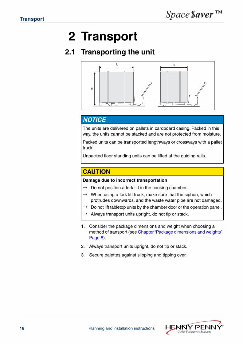
2 Transport2.1 Transporting the unit
L
H
B
NOTICEThe units are delivered on pallets in cardboard casing. Packed in thisway, the units cannot be stacked and are not protected from moisture.
Packed units can be transported lengthways or crossways with a pallettruck.
Unpacked floor standing units can be lifted at the guiding rails.
CAUTIONDamage due to incorrect transportation
→ Do not position a fork lift in the cooking chamber.→ When using a fork lift truck, make sure that the siphon, which
protrudes downwards, and the waste water pipe are not damaged.→ Do not lift tabletop units by the chamber door or the operation panel.→ Always transport units upright, do not tip or stack.
1. Consider the package dimensions and weight when choosing amethod of transport (see Chapter “Package dimensions and weights”,Page 8).
2. Always transport units upright, do not tip or stack.
3. Secure palettes against slipping and tipping over.
Global Foodservice SolutionsPlanning and installation instructions16
Space$aver™Transport

3 Installation3.1 Installation information
Before installing NOTICEExamine the unit for transportation damage. Do not install or usedamaged units.
Remove the protective film from the external panels before using forthe first time.
Remove foam transport protection from the chamber.
Fire prevention regulations NOTICEObserve the local fire prevention regulations when installing near tomaterials that are heat sensitive or endangered by fire.
Covers on top of the unit must be fire-proof.
Units may only be installed on or against fire-proof surfaces and incompliance with fire prevention regulations.
Installation in buildings The floor or table must be able to bear the weight of the unit (seeChapter “Weight”, Page 9).
Minimum clearances On the sides and at the back, maintain at least 50 mm (2") clearanceto the walls; above the unit at least 0.5 m (1.6 ft.) clearance, to enableservice work to be performed.
Heat sources such as ovens (2) must be at least 0.5 m (1.6 ft.) awayfrom the unit so that the cooling air drawn in under the base is notwarmed.
WARNINGPossible danger→ Non-compliance may pose a threat of death or serious injury.
Fryers or deep fat fryers must be positioned outside of the splash zone(3) of the hand shower. Splashes of water in hot grease can lead toserious burns.
17Planning and installation instructionsGlobal Foodservice Solutions
InstallationSpace$aver™

Air intake and blow outvents
NOTICEUnits in the SpaceSaver and SpaceSaver PLUS versions are not suitablefor installation within a closed housing!
The air intake and blow out vents are situated at the rear of the unit.
1
2
Make sure that extracted air from the blow-out vent (2) is not drawn intothe intake vent (1).
Affix “Risk of scalding”warning
If units are installed so that the upper slide-in rails exceed a height of 1.60m (5.3 ft.) a warning notice must be mounted on the cooking chamberdoor.
The warning “Risk of scalding” warns about the danger of scalding thatexists when the contents of a container being pulled out cannot be seen.
3.2 Mounting the suspension frame in thebase frameThe base frame can be retrofitted with suspension frames for taking GNcontainers, trays and racks.
Global Foodservice SolutionsPlanning and installation instructions18
Space$aver™Installation

Figure 3: Suspension frame in the base frame
1. Mount the inner suspension frame.
2. Push the rear stop profiles onto the bolts.
3. Mount the outer suspension frame.
19Planning and installation instructionsGlobal Foodservice Solutions
InstallationSpace$aver™

3.3 Installing tabletop units
NOTICEA warning notice must be mounted on the door of the cooking chamberif tabletop units are installed in such a way that the upper slide-in railsexceed a height of 1.60 m (5.3 ft.).
The label warns about the danger of scalding that exists when thecontents of a container being pulled out cannot be seen.
1. Observe the instructions for installation (see Chapter “Installationinformation”, Page 17).
2. Make sure that the table is able to bear the weight of the unit.
3. Position the unit horizontally level. Correct the alignment using thefeet, if necessary.
4. Remove moisture and grease from the area for affixing the warningnotice.
5. Attach the warning notice on the door of the cooking chamber.
3.4 Setting up with a stacking kitRequirements Stacking kit is assembled
1. Place the lower unit in the stacking kit.
2. Insert the exhaust pipe on the exhaust nozzle until it lies against thestop.Apply liquid detergent to the sealing rings to make installation easier.
Global Foodservice SolutionsPlanning and installation instructions20
Space$aver™Installation
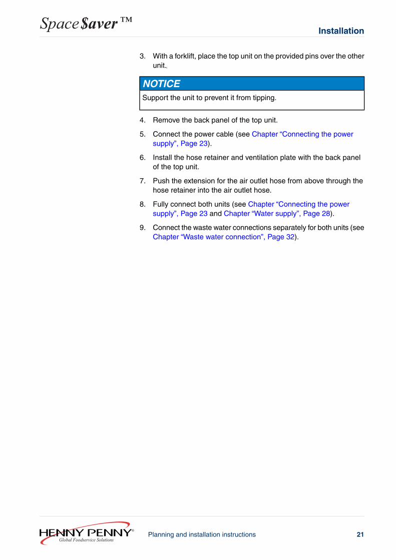
3. With a forklift, place the top unit on the provided pins over the otherunit.
NOTICESupport the unit to prevent it from tipping.
4. Remove the back panel of the top unit.
5. Connect the power cable (see Chapter “Connecting the powersupply”, Page 23).
6. Install the hose retainer and ventilation plate with the back panelof the top unit.
7. Push the extension for the air outlet hose from above through thehose retainer into the air outlet hose.
8. Fully connect both units (see Chapter “Connecting the powersupply”, Page 23 and Chapter “Water supply”, Page 28).
9. Connect the waste water connections separately for both units (seeChapter “Waste water connection”, Page 32).
21Planning and installation instructionsGlobal Foodservice Solutions
InstallationSpace$aver™

4 Electricity4.1 Cable requirements
The unit is delivered as standard without a connection cable. A H07RN-Fcable complying with EN standards or, respectively, with the locallyapplying provisions, must be used for connecting the unit.
4.2 Description of the terminal strip
A1/X
5.11
A1/X
5.12
K1/A
2
K1/A
2
X3
X2PE
PE PE PE13 N 11 12
15 16
A1/X
4.3
A1/X
6.7
K1/1
4
A1/X
5.16
A1/X
5.15
PEDA B C
1 2 3 4
A_TX
D+B_
TXD-
B_RX
D-A_
RXD+
YE G
N BN WH
H13/
A1
R = 150 Ω
Figure 4: Terminal strip
Global Foodservice SolutionsPlanning and installation instructions22
Space$aver™Electricity

DescriptionTerminalTerminalstrip
Performance optimization system (LOA)AX2
B
C
D
PE
15
16
PE
External buzzer
External signalling device activated via an auxiliaryrelay.
13
X3
N
PE
Extraction hood, potential-free11
12
PE
RS485/RS422 interface1
2
3
4
PE
4.3 Connecting the power supplyThe unit may only be connected and serviced by an authorised electricaltechnician, according to the provisions of the German Association ofElectrical Technicians, the power supply company and the informationon the nameplate.
Have damaged power cables replaced by customer service to avoidrisks of damage or injury.
The unit can be connected to the mains with a fixed connection or witha plug.
Isolator with direct connections
The power supply must be fitted with an all pole isolator (e.g. automaticcutout) with a minimum contact opening of 3 mm, so that the unit canbe removed from the mains at any time.
Plug connection
The plug socket must be adequately protected.
Potential equalisation
The unit can be included in a potential equalisation system (grounding).The connection terminal is underneath the information plate.
23Planning and installation instructionsGlobal Foodservice Solutions
ElectricitySpace$aver™

4.3.1 Three-phase power connection
The unit is delivered without a power cable and with a three-phase terminalconnection.
1. Prepare the connection cable (cable type H07RN-F compliant withEN-Norm).
2. Remove the back panel.
3. Pass the connection cable through the strain relief screws into theunit.
4. Tighten the strain-relief screws securely so that the power cablecannot be pulled out.
5. Connect the power cable to the terminals.
6. Remount the back panel.
4.3.2 Single-phase power connection (only SpaceSaver)
The unit is delivered without a power cable and with a three-phase terminalconnection.
NOTICESize 605 units in the 380 V, 400 V and 415 V versions can also besingle-phase connected.
The unit's connected output is reduced with a single-phase connection(see Chapter “Specifications, power supply”, Page 13).
Global Foodservice SolutionsPlanning and installation instructions24
Space$aver™Electricity

A B
If the unit is to be connected to the mains as a single-phase appliance,the contactor terminal connections and those of the electronic relaymust be changed. The contactor's terminal blocks are located underthe cover on the left at the back (A). The electronic relay is under thecover on the right at the back (B).
1. Prepare the connection cable (cable type H07RN-F compliant withEN-Norm).
2. Remove covers.
3. At the contactor, connect the blue wire from terminal Y to terminalN.
4. At the electronic relay, connect the black wire from terminal V1 /2/T1 to terminal V2 / 2/T2.
5. Replace covers.
6. Remove the back panel.
7. Pass the connection cable through the strain relief screws into theunit.
8. Tighten the strain-relief screws securely so that the power cablecannot be pulled out.
25Planning and installation instructionsGlobal Foodservice Solutions
ElectricitySpace$aver™

9. Connect the power cable to the terminals.
10. Remount the back panel.
4.4 RS485/RS422 interfaceUnits in the SpaceSaver and SpaceSaver PLUS versions are equippedwith a four-pin RS485 interface as standard.The interface can be reducedto a two-pin RS422 interface.
1. Bridge the terminals to reduce the interface to a two-pole RS422interface.- X3/1 to X3/3- X3/2 to X3/4
2. Use twisted wires (e. g. LiYY (TP) 2x2x0.5) for the connection.
3. Close the last unit with a 150 Ω terminating bus resistor.
4.5 Connect performance optimization system(LOA)Units in the SpaceSaver and SpaceSaver PLUS versions are equippedwith a performance optimisation system (LOA) as standard.
With this system, 230 V signals are passed on to an external performanceoptimization system. By means of this signal, the system can interruptthe heating cycle and stop heating.
The LOA connection is compatible to systems from SICOTRONIC GmbH.
Global Foodservice SolutionsPlanning and installation instructions26
Space$aver™Electricity

1. Remove the back panel.
2. Pass the LOA connection cable through the strain relief screwsinto the unit.
3. Tighten the strain-relief screws securely so that the LOA connectioncable cannot be pulled out.
1
Figure 5: Connecting the performance optimization system (LOA)
4. Connect the LOA connection cable to the terminal strip (1), (seeChapter “Description of the terminal strip”, Page 22).
5. Remount the back panel.
27Planning and installation instructionsGlobal Foodservice Solutions
ElectricitySpace$aver™

5 Water5.1 Water supply
The unit is equipped with two water connections:
● a soft water connection for producing steam● a hard water connection for cooling waste water, for operating the
hand shower and for the automatic cleaning system “WaveClean”For units that are equipped with the “WaveClean” automatic cleaningsystem, use of “WaveClean” is not possible without a hard waterconnection.
NOTICEBoth water supplies must always be connected.
Hard and soft water connections can be made via a hose with a T-piece(accessory) in the event that only soft water is available on site (seeChapter “Fitting the T-piece (accessory)”, Page 30).
NOTICEWhen using the stacking kit (accessory), the upper and lower units mustbe connected independently so that the other unit can still be used inthe event that one unit fails.
1. Observe information about the hard water supply (see Chapter“Information about the hard water supply”, Page 30).
2. Observe information about the soft water supply (see Chapter“Information about the soft water supply”, Page 29).
3. Ensure that customer-supplied water hoses fulfil the requirementsfor the hard and soft water supplies (see Chapter “Specifications, softwater”, Page 13 and Chapter “Specifications, hard water”, Page 13).
4. Make sure that the provisions for the supply of drinking water arecomplied with (see Chapter “Water”, Page 5).
5. Ensure that the water stop-cock is fitted with a backflow preventer.
6. Use ½" hoses with an R ¾" thread permitted for connecting drinkingwater for the connection.
NOTICEUse DVGW-tested hoses, or hoses conforming to the local regulations,according to IEC 61770.
Global Foodservice SolutionsPlanning and installation instructions28
Space$aver™Water

7. When preparing the hoses, calculate the length to allow 0.8 m tobe pulled out from the unit after connection, for later servicing.
8. Rinse out customer-supplied hoses for the hard and soft waterconnections.
9. Make sure that the filters fitted as standard to the unit's water inletsare present.
CAUTIONDamages caused by incorrect water supply!
→ Do not confuse the hard water and the soft water connections.
NOTICEThe connections for hard and soft water are located on the floor ofthe unit on the left.
2
1
10. Connect the hose for the hard water supply to the hard waterconnection (1).
11. Connect the hose for the soft water supply to the soft waterconnection (2).
5.1.1 Information about the soft water supply
Cl/Fe content If the Cl content is greater than 150 mg/l, Fe content greaterthan 0.1 mg/l or Cl2 content greater than 0.1 mg/l, corrosion can occur
in the cooking chamber. The Cl content can be reduced with anactivated charcoal filter.
Supply pressure If the supply pressure is not within the given limits (see Chapter“Specifications, soft water”, Page 13), the cooking art “Steaming” willfail to produce any steam.
Contamination of the water If the water is heavily contaminated, a sedimentation filter (grit size0.08 mm) must be installed upstream.
29Planning and installation instructionsGlobal Foodservice Solutions
WaterSpace$aver™

Water hardness Scale deposits may form if the total water hardness or carbonate hardnessexceeds 5 °dH (0.89 mmol/l). For values smaller than this, the scaleformation is correspondingly less. A total water hardness or carbonate
hardness of 1 °dH is ideal. Certain water components (Na+ ions andsilicates) can cause the windows to become cloudy. This effect dependson the quality of the water and how the unit is used. Decarbonisation orfull desalination systems can prevent the formation of scale deposits.
A water softening system should be installed upstream if the water is veryhard.
Water softening systems based on electromagnetic fields do not provideprotection against scale deposits with combisteamers.
Pipes from galvanized steel or other corrosive material may not be useddownstream from water softening systems.
Systems with phosphate and silicate dosing may not be used. Depositsmay form in the cooking chamber with such systems.
Units in the SpaceSaver and SpaceSaver PLUS versions can display themaintenance intervals of a connected water softening system on theMulti-function display.You will find further information in the operatinginstructions.
5.1.2 Information about the hard water supply
Cooling waste steam Cold water that has not been softened can be used for cooling wastesteam.
Warm water leads to increased water consumption and should not beused.
The water temperature must not exceed 50 °C (122 °F).
Automatic cleaning system“WaveClean”
Units that are equipped with the “WaveClean” automatic cleaning systemmust always be connected to a hard water and a soft water supply.
Otherwise, cleaning with “WaveClean” is not possible.
5.1.3 Fitting the T-piece (accessory)
Hard and soft water connections can be made via a hose with a T-piece(accessory) in the event that only soft water is available on site.
Global Foodservice SolutionsPlanning and installation instructions30
Space$aver™Water

Figure 6: Position of the T-piece
1
2
3
Figure 7: Parts of the T-piece
1 Sealing ring
2 Threaded connector
3 Metal ring
1. Check that both sealing rings (1) are lying flat in the threadedconnectors (2).
2. Screw the threaded connectors (2) evenly onto the hard and softwater connections and tighten securely. Avoid cross-threading.
31Planning and installation instructionsGlobal Foodservice Solutions
WaterSpace$aver™

CAUTIONDamage to the unit caused by water
→ Check that the metal rings are positioned correctly.
3. Check that both metals rings (3) are lying on the respective plasticsprocket in the threaded connector (2).If not, open the threaded connector (2) and repeat the process.
5.2 Waste water connectionThe unit is equipped with a siphon (odour trap) with an overflow and canbe connected to the waste water system without taking additional action.Customer-supplied siphons should be avoided.
1
2
3
If the waste water outlet is connected to a customer-supplied siphon (1),counter pressure may cause the siphon in the unit (3) to overflow.Therefore, in this case, the waste water pipe must be fitted with an aerator.
A PA-I 1818 DIN 19560 HT pipe is recommended for the connection tothe waste water system.
The diameter of the waste water pipe must not be reduced.
1. Make sure that the customer-supplied pipes meet the requirementsfor the waste water connection (see Chapter “Specifications, wastewater”, Page 13).
2. Observe the provisions for the disposal of waste water (see Chapter“Waste water”, Page 5).
3. Connect the unit to the waste water system using a heat-proof pipe(DN 40).
4. With customer-supplied siphons: connect aerator to a waste waterpipe.
5. With customer-supplied siphons: pour 2 quarts (2 l) of drinking waterinto the siphon.
This ensures the siphon will work properly.
Global Foodservice SolutionsPlanning and installation instructions32
Space$aver™Water

6 Air outlet connectionWaste steam and vapours are cooled by the built-in cooling systemand extracted via the drain; an air extraction system is therefore notessential.
Installation under an extraction hood is recommended.
6.1 Installation under an extraction hood→ Observe the regulations for room ventilation systems (see Chapter
“Room air”, Page 6).
6.2 Connection to an air outlet ductRequirements Connection with a pipe
● Do not use galvanized pipes.● Heat-proof and non-corrosive pipe (e.g. PA-I 1818 DIN 19560 HT
pipe)Connection with a hose
● Do not use aluminium tubes because tube corrosion might occur.● Heat-proof to at least 180 °C (356 °F)● Hose diameter 30 mm● Hose length 1.5 m
The end of the hose must not be connected directly to an air-outlet duct(e.g. extraction hood). Counter-pressure will cause steam to be drawnoff from the cooking chamber; this will impair the cooking results. Theend of the hose should end below (outside) the air-outlet duct.
1. Connect the unit to an air-outlet duct using a pipe or a hose.
2. Take care not to create a “water pocket” (sagging when laidhorizontally), and that the cross-section is not restricted.
33Planning and installation instructionsGlobal Foodservice Solutions
Air outlet connectionSpace$aver™

Global Foodservice SolutionsPlanning and installation instructions34
Space$aver™Air outlet connection
Planning and installation instructions
Space$aver™

Global Foodservice Solutions
Henny Penny CorporationP.O. Box 60Eaton, OH 45320
1-937-456-84001-937-456-8402 Fax Toll free in USA 1-800-417-84171-800-417-8434 Fax
www.hennypenny.com
Manufactured by: MKN MaschinenfabrikWolfenb¿ttel, Germany
Planning and installation instructions
Space$aver™