planmeca plancad® user manual · 2020-02-04 · table of contents introduction
TRANSCRIPT

Planmeca PlanCAD® User Manual

Table of ContentsIntroduction . . . . . . . . . . . . . . . . . . . . . . . . . . . . . . . . . . . . . . . . . . . . . . . . . . . . . . . . . . . . . . . . . . . . . . . . . . . . . 4
Associated Documentation ........................................................................................................................................................................................................... 4Indications for Use ............................................................................................................................................................................................................................ 4Contraindications .............................................................................................................................................................................................................................. 4Turn ON Laptop ................................................................................................................................................................................................................................. 4Opening Romexis .............................................................................................................................................................................................................................. 4
Moving/Viewing the 3D Model ...................................................................................................................... 5Rotating the Model ................................................................................................................................................................................................................ 5Changing the Model Size .................................................................................................................................................................................................... 5Moving the Model ................................................................................................................................................................................................................. 5
System Options and Default Settings ........................................................................................................... 5Screenshots ......................................................................................................................................................................................................................................... 6The Settings Screens ........................................................................................................................................................................................................................ 6
Relocating the Laptop .................................................................................................................................... 8System Information and Upgrades ............................................................................................................... 8
Software and Hardware .................................................................................................................................................................................................................. 8Additional Assistance ..................................................................................................................................... 8
Importing Data . . . . . . . . . . . . . . . . . . . . . . . . . . . . . . . . . . . . . . . . . . . . . . . . . . . . . . . . . . . . . . . . . . . . . . . . . . 9Importing a CAD/CAM Case ........................................................................................................................... 9Importing 3D Models .................................................................................................................................... 10
3D Model Import .............................................................................................................................................................................................................................10To import models from an external source: ...............................................................................................................................................................10
Setting Up a Restoration . . . . . . . . . . . . . . . . . . . . . . . . . . . . . . . . . . . . . . . . . . . . . . . . . . . . . . . . . . . . . . . . . 11Managing Patients in Planmeca Romexis ................................................................................................... 11
Creating new patients ...................................................................................................................................................................................................................11Searching Patients ..........................................................................................................................................................................................................................11Sorting patients ...............................................................................................................................................................................................................................11Selecting and opening patients ................................................................................................................................................................................................12
Managing Cases ............................................................................................................................................ 12Deleting Files ................................................................................................................................................. 12Starting a New Restoration .......................................................................................................................... 12Setup Screen ................................................................................................................................................. 13Smile Design .................................................................................................................................................. 14
Block Selection .................................................................................................................................................................................................................................15ZirCAD Material Selection ............................................................................................................................................................................................................15Changing the Tooth Selection ....................................................................................................................................................................................................16Designating a Bridge .....................................................................................................................................................................................................................16Unlinking a Bridge ..........................................................................................................................................................................................................................16
Orientation . . . . . . . . . . . . . . . . . . . . . . . . . . . . . . . . . . . . . . . . . . . . . . . . . . . . . . . . . . . . . . . . . . . . . . . . . . . . . 17Viewing the model ........................................................................................................................................ 17Single Restorations ....................................................................................................................................... 18
Occlusal View ....................................................................................................................................................................................................................................18Distal View ...............................................................................................................................................................................................................................18
Resetting the Orientation ............................................................................................................................ 19Multiple Restorations ................................................................................................................................... 19
Margin Tab . . . . . . . . . . . . . . . . . . . . . . . . . . . . . . . . . . . . . . . . . . . . . . . . . . . . . . . . . . . . . . . . . . . . . . . . . . . . . 21Margin Tool .................................................................................................................................................... 21
Margin Aids .......................................................................................................................................................................................................................................21View ICE Preparation ...........................................................................................................................................................................................................21Show Features .......................................................................................................................................................................................................................22
Creating the Margin ...................................................................................................................................... 22Paint tool ............................................................................................................................................................................................................................................22Trace tool ............................................................................................................................................................................................................................................22
Lasso tool ................................................................................................................................................................................................................................23Margin Tab Settings ...................................................................................................................................... 23
ICE Margin Mode .............................................................................................................................................................................................................................23For intraoral cases only. .................................................................................................................................................................................................................23
©January 2020 Planmeca All rights reserved. Software version 6.2 10828300.H
Planmeca PlanCAD User Manual 1

Modifying the Margin ................................................................................................................................... 24Toggle Margin........................................................................................................................................................................................................................24Move Margin tool .................................................................................................................................................................................................................24Add Segments tool ..............................................................................................................................................................................................................24
Retract ............................................................................................................................................................ 25Multiple Restorations ................................................................................................................................... 25Drawing Pontic Margins ............................................................................................................................... 26Selection Area Tool ....................................................................................................................................... 26
Remove From Selection ................................................................................................................................................................................................................27Reset ....................................................................................................................................................................................................................................................27
Pre-op Editing ............................................................................................................................................... 28Trace .....................................................................................................................................................................................................................................................28Move Curve .......................................................................................................................................................................................................................................28Add Segments ..................................................................................................................................................................................................................................28
Contralateral ..........................................................................................................................................................................................................................28
Plan Screen . . . . . . . . . . . . . . . . . . . . . . . . . . . . . . . . . . . . . . . . . . . . . . . . . . . . . . . . . . . . . . . . . . . . . . . . . . . . . 29Designing the Restoration . . . . . . . . . . . . . . . . . . . . . . . . . . . . . . . . . . . . . . . . . . . . . . . . . . . . . . . . . . . . . . . 30
Tooth Libraries .............................................................................................................................................. 30Select a Library ......................................................................................................................................................................................................................30Anatomy Levels .....................................................................................................................................................................................................................30Contralateral ..........................................................................................................................................................................................................................30Apply the changes ...............................................................................................................................................................................................................31
Pre-op as Library Tooth .................................................................................................................................................................................................................31Viewing Options ............................................................................................................................................ 31
Hide Model .............................................................................................................................................................................................................................31Material Thickness ................................................................................................................................................................................................................31Measure ...................................................................................................................................................................................................................................32View Contacts ........................................................................................................................................................................................................................32Slice Plane ...............................................................................................................................................................................................................................32View Bite Registration, Opposing Model, or Pre-op ...............................................................................................................................................33
Incremental Change Tools ............................................................................................................................ 34Rotate ..................................................................................................................................................................................................................................................34Move ....................................................................................................................................................................................................................................................34Expand ................................................................................................................................................................................................................................................34
Freeform Change Tools ................................................................................................................................. 35Rubber Tooth ....................................................................................................................................................................................................................................35Dropper ..............................................................................................................................................................................................................................................36Move Feature ....................................................................................................................................................................................................................................36Smooth Surface ...............................................................................................................................................................................................................................36Move Margin .....................................................................................................................................................................................................................................37Define Feature ..................................................................................................................................................................................................................................37Paint Feature .....................................................................................................................................................................................................................................37
Contact Refinement ...................................................................................................................................... 38Spacer Tool .................................................................................................................................................... 39
Bridge Spacer Settings ..................................................................................................................................................................................................................39Design Tab Settings ...................................................................................................................................... 39
Autogenesis Settings .....................................................................................................................................................................................................................39Contact Strengths ...........................................................................................................................................................................................................................40Margin Boost .....................................................................................................................................................................................................................................40
Designing Multiples ...................................................................................................................................... 41Contralateral Tooth Copy ............................................................................................................................. 41Copy Contralateral Dentition ....................................................................................................................... 41
Copy a Restoration Design ..........................................................................................................................................................................................................42
Mill Tab . . . . . . . . . . . . . . . . . . . . . . . . . . . . . . . . . . . . . . . . . . . . . . . . . . . . . . . . . . . . . . . . . . . . . . . . . . . . . . . . . 43Setting up the restoration for milling ......................................................................................................... 43
Select a Block Size ...........................................................................................................................................................................................................................43Sprue Placement .............................................................................................................................................................................................................................44Restoration Positioning ................................................................................................................................................................................................................44Mill Simulation .................................................................................................................................................................................................................................45
IPS e.max ZirCAD Simulation and Milling ....................................................................................................................................................................45Evaluate the simulation .....................................................................................................................................................................................................45
Evaluating the Connectors on Bridges ........................................................................................................ 46Send to Mill .................................................................................................................................................... 48Mill Tab Settings ............................................................................................................................................ 48
Mill Network Settings .........................................................................................................................................................................................................48Material/Shade Settings ....................................................................................................................................................................................................48Margin Thickness Settings ................................................................................................................................................................................................48
Planmeca PlanCAD User Manual 2

Milling Settings .....................................................................................................................................................................................................................48Simulation Settings .............................................................................................................................................................................................................49
Troubleshooting ........................................................................................................................................... 49Exporting Data . . . . . . . . . . . . . . . . . . . . . . . . . . . . . . . . . . . . . . . . . . . . . . . . . . . . . . . . . . . . . . . . . . . . . . . . . . 50
Exporting a CAD/CAM Case .......................................................................................................................... 50Exporting 3D Models .................................................................................................................................... 50
3D Model Export .............................................................................................................................................................................................................................50DDX Export .................................................................................................................................................... 50
Selecting a Case ...............................................................................................................................................................................................................................51DDX Website .....................................................................................................................................................................................................................................51
Planmeca PlanCAD User Manual 3

IntroductionThe Planmeca FitTM System is a complete optical impression system for CAD/CAM of dental restorations intended for dental offices or laboratories. The system comprises a Planmeca optical impression scanner, Planmeca Romexis CAD/CAM design software module, and Planmeca PlanMill.
The Planmeca scanner takes digital impressions which can be designed and customized on the Planmeca Romexis CAD/CAM design software. The impressions can be sent via Planmeca Romexis Cloud to Planmeca or a certified laboratory for design and milling or exported to a third party.
The Planmeca Fit System requires Planmeca Romexis software revision 3.4.0.R or later.
Associated Documentation
Planmeca Romexis User’s Manual (publication number 10014593).
Throughout the documentation, important notes and items of interest are formatted like this example.
Some of the screenshots may have been taken in earlier software versions and may not exactly match your screen.
Indications for Use
The Optical Impression Scanner is an optical impression system used to record the topographical characteristics of the dentition and/or full arch and preparation areas (including features such as implant scan locator fixtures, braces, brackets, etc.). In addition it can record the topographical characteristics of the oral anatomy (such as soft tissue, gingivae and palate).
The three dimensional model generated from the scan may be further used for study models, and for the design and manufacturing of dental restorations including implant supported prostheses and full and partial frameworks, and can be used to design and manufacture physical models of the teeth.
It may be used in conjunction with production of orthodontic appliances, retainer and accessories.
The Planmeca PlanCAD system is used to design dental restorations.
Contraindications
None known.
Turn ON Laptop
Press the power button to start the laptop.
Opening Romexis
Click the Romexis icon on your desktop to open the software.
Planmeca PlanCAD User Manual Introduction 4

Planmeca PlanCAD User Manual Introduction 5
Moving/Viewing the 3D ModelUse the mouse to zoom in or out, move, and rotate the composite model.
Rotating the Model
1 Click and hold down the right mouse button.
The pointer changes to .
2 Drag the mouse horizontally, vertically, or diagonally to rotate the image.
Drag in small increments for more control.
3 Release the mouse button to stop rotating. Repeat as needed.
Changing the Model Size
Use the scroll wheel on the mouse to zoom in and out on the model.
1 Position the pointer on your model.
2 Rotate the mouse wheel downward, toward your wrist.
The pointer changes to and the model becomes smaller.
3 Rotate the mouse wheel upward, away from your wrist.
The model becomes larger.
Moving the Model
The model can be moved without being rotated.
1 Position the pointer on the model.
2 Press and hold down the mouse wheel.
The pointer changes to .
3 Drag the model to the desired position and release the mouse wheel.
System Options and Default SettingsIndividual tabs are used to design the restoration: Setup, Scan, Margin, Design, and Mill. The tabs are dynamic. The choices you make on each tab affect the options available on that and related tabs. The typical restoration utilizes the tabs from left to right. Moving backwards in the process (e.g., modifying the settings in the Margin tab after completing the design in the Design tab) can cause settings and designs to be discarded. The system warns you when your actions will cause design data to be discarded.
Some system configurations will restrict the use and access of individual tabs.

Planmeca PlanCAD User Manual Introduction 6
Screenshots
You can save an image of the screen for communicating with associates or Customer Support. The directions vary based on the keyboard setup on your laptop.
Look for the Print Screen button (Prt Scr) on your keyboard:
• If Print Screen is in white or black font (matches the rest of the keyboard), press + Prt Sc keys simultaneously.
• If Print Screen is in blue text on the function keys, press + Fn + Prt Sc keys simultaneously.
The computer takes a screenshot and saves it in Libraries - Pictures - Screenshots.
The screenshots are automatically numbered. You can rename them if desired.
If you are using a 3rd party laptop, please refer to that computer’s user manual for how to take and retrieve screenshots.
The Settings Screens
Click the Settings button on the CAD/CAM screen or the Settings button on each tab. These screens contain preference settings that modify the default behavior of the software. The settings are based on each screen. Use the arrows to scroll right or left. Click a category to select it. Selected categories display in the bottom of the screen.
Click Restore Factory Defaults to revert to original settings, click Save to save changes, or click Cancel to exit without saving.
VersionDisplays the version of the software and imaging systems.
Reset WarningsThe warning and reminder screens have an option to Do Not Show This Message Again. If a new operator is using the system, you can reactivate these warnings.
Sprue Angle Method (For mill systems)
The default setting is Tooth Specific. Tooth Specific places the sprue in the most commonly recommended position based on the type of restoration. Optimized selects the placement based on the fastest milling time. In all cases, the sprue can be manually moved on the Mill tab.
Margin Ramp Default: 0.25. Default setting for the margin ramp incline. Use the slider or type a number in the box to change the setting.
Increasing the Margin Ramp decreases the space between the restoration and preparation at the shoulder. Decreasing the Margin Ramp increases this space.
Spacer Thickness Default: 0.1 Top: 0.1 Sides
Default setting for the space between the preparation and the restoration.
Planmeca PlanCAD User Manual Introduction 7
Dropper ToolDefault: 0.040 Thickness: 2.000 Width
Default setting for the dropper tool has an amount/thickness of material and how much surface area it covers.
Spaceball Settings(Optional accessory)
Mill Network Settings(For Mill Systems)
If you have multiple mills on your network, you can set them up here.
• To add a new mill to the network, type the Mill Name and IP Address then click the Plus sign in the top right.
• To edit one of the mills, click the name in the list and edit the details on the left.
• To remove a mill, click the name in the list and then click the Minus sign in the top right.
• Highlight a mill name and select the Favorite checkbox to designate this mill as the default option on the Mill tab.
Network SettingsThis screen should be used only under the supervision of a customer service representative. These settings are pre-configured and should not be changed.
Workbook Exercises(For Classic systems)
Mill Notification Settings(For Classic systems)
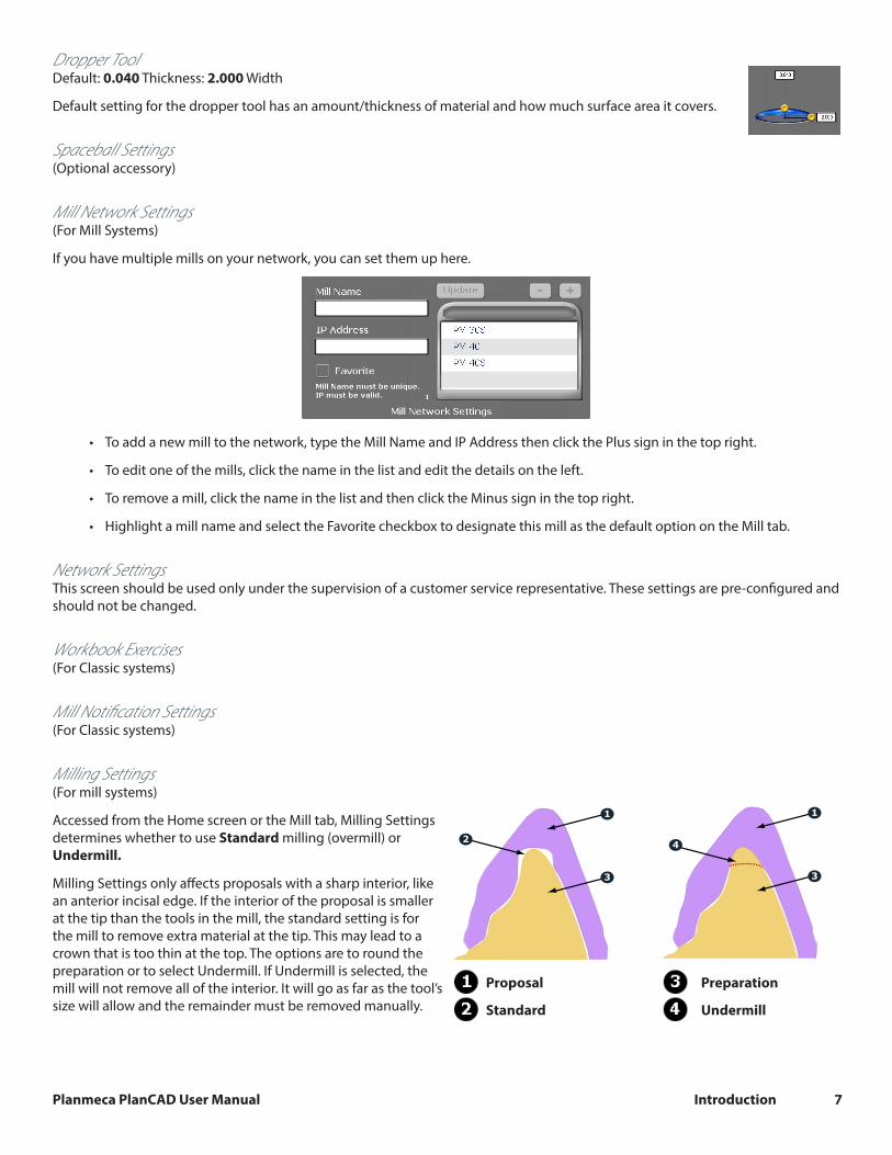
Milling Settings(For mill systems)
Accessed from the Home screen or the Mill tab, Milling Settings determines whether to use Standard milling (overmill) or Undermill.
Milling Settings only affects proposals with a sharp interior, like an anterior incisal edge. If the interior of the proposal is smaller at the tip than the tools in the mill, the standard setting is for the mill to remove extra material at the tip. This may lead to a crown that is too thin at the top. The options are to round the preparation or to select Undermill. If Undermill is selected, the mill will not remove all of the interior. It will go as far as the tool’s size will allow and the remainder must be removed manually.
1
2
3
1
4
3
Proposal Preparation
Standard Undermill
Planmeca PlanCAD User Manual Introduction 8
Auto or Occlusal POI(For mill systems)
This should only be changed at the request of Customer Support. Auto POI (Orientation) finds the best possible milling path to avoid undercuts and this eliminates the need to go back (on veneer and multiple cases especially) and reset POI for the mill. Occlusal POI uses the Orientation to set the tool path.
Relocating the LaptopThe laptop can be unplugged and moved as needed. The software does not need to be shut down.
System Information and Upgrades
Software and Hardware
System software and hardware upgrades are initiated through Planmeca only. No software or hardware should be added or deleted to/from the Planmeca systems without prior approval of Planmeca. Doing so may result in damage to the system and will void the product warranty.
Additional AssistanceGo to http://planmeca.com/training for information about training. If you have questions, please contact Customer Support at:
Toll Free 800-537-6070
E-mail [email protected]
Hours of Operation 7 am – 6 pm CST (Monday - Friday)
Web site wwwplanmeca.com
Mailing AddressPlanmeca USA 2600 Forbs Ave Hoffman Estate, IL 60192

Planmeca PlanCAD User Manual Importing Data 9
Importing DataThe screenshots in this chapter are of Romexis and may have changed since this manual was published. Please see the
Romexis User Manual or www.planmeca.com for more information on Romexis.
There are several methods for sharing digital information using Romexis.
• CAD/CAM cases can be transferred between other Planmeca or E4D systems.
• STL files of CAD/CAM data can be imported and exported as 3D Models to and from an external source.
• Securely receive cases over the internet using Planmeca Romexis Cloud services (see Romexis manual) or as a lab through DDX.
Importing a CAD/CAM CaseYou can import a case from another Planmeca or E4D system into Romexis.
1 Open the desired patient file.
2 In Romexis, click File - Import - Import CAD/CAM Case.
3 A new screen appears. Click Next.
4 A new screen appears. Click Browse to find the file with the time and date stamp as the folder name, ex. [3-25-2014 10:37:42 AM].
• If you have exported the files from another Planmeca system, a .zip file is created with the restoration number(s) as the name. Extract the files and open the folder to find the time and date stamped folder.
• E4D patient files are stored under the customer name (or whatever naming convention that was used) in the E4D system at c:\d4d\DesignCenter\patients\PatientName\restorations\
5 Select how you want to import it:
• Import to current patient (if in a patient file)
• Create new patient (available when there are no patient files currently open)
• Select an existing patient (available when no patient files are currently open)
The selected CAD/CAM case will be imported into the Patient’s Case Files list within the CAD/CAM Module.

Planmeca PlanCAD User Manual Importing Data 10
Importing 3D Models
3D Model Import
To import models into the CAD/CAM Module click 3D model import.
The following window opens.
You may import STL models from an external source, additional licensing may be required.
To import models from an external source:
1 Click Browse.
2 Browse to the folder from where you want to import the models.
3 Select the STL file and click Open.
The imported case will appear in the Patient’s Case Files list. You will only import the Prep & Opposing STL models. Bite alignment is from the external source.
Planmeca PlanCAD User Manual Setting Up a Restoration 11
Setting Up a Restoration
Managing Patients in Planmeca Romexis
Creating new patients
1 In Patient Management, click the Add Patient button.
The Add Patient screen opens.
2 Enter the necessary information and add a face photo if desired.
The obligatory fields are in bold text. See the Romexis User Manual for more information.
3 To save the patient into the database click the Save button in any section.
The changes are not saved unless Save button is used.
To view the newly created patient on the list, perform new patient search.
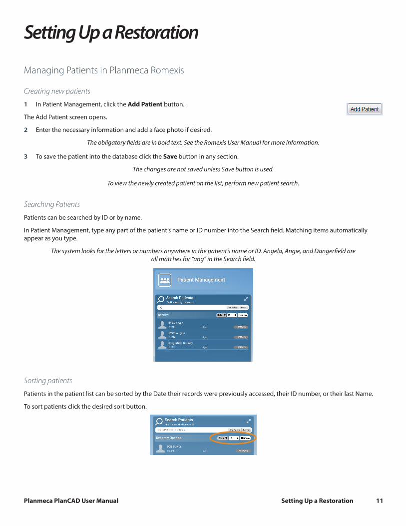
Searching Patients
Patients can be searched by ID or by name.
In Patient Management, type any part of the patient’s name or ID number into the Search field. Matching items automatically appear as you type.
The system looks for the letters or numbers anywhere in the patient’s name or ID. Angela, Angie, and Dangerfield are all matches for “ang” in the Search field.
Sorting patients
Patients in the patient list can be sorted by the Date their records were previously accessed, their ID number, or their last Name.
To sort patients click the desired sort button.

Planmeca PlanCAD User Manual Setting Up a Restoration 12
Selecting and opening patients
1 Click the patient name in the patient list.
The patient’s file opens.
The name of the active patient is always visible in the upper right corner of the screen. Several patient records can be open at a time but only one of the open records is active at a time.
To close the active patient click the Close Patient button.
To view all open patients click the arrow of the drop-down menu.
To select and modify another open patient, select the name from the drop-down menu.
2 Click Go to CAD/CAM in the Next Steps section at the bottom of the screen or on the Charms menu on the left side of the screen.
Managing Cases1 Open the desired patient.
2 Click Go to CAD/CAM.
Select what you want to do:
• Start a new restoration - See below for more information
• Open an existing restoration - See below for more information
• Import 3D models - See Planmeca Romexis User’s manual for more information
• Export 3D models - See Planmeca Romexis User’s manual for more information
Deleting FilesTo delete an image (stl file) from the patient’s case files right-click on the file and select Inactivate STL.
To delete a case from the patient’s case files right-click on the case and select Inactivate restoration.
To reactivate or permanently delete a case from the database see the Romexis User Manual.
Starting a New Restoration1 To start a new scan, click New Scan and Design.
2 To open an existing scan or restoration (crown, inlay, onlay, etc.) double-click a case on the list or click the Open Restoration button.
Click Open for Design Only if you do not have a scanning license.
The case opens in the Setup screen.

Planmeca PlanCAD User Manual Setting Up a Restoration 13
Setup ScreenUse the Setup screen to set the restoration type, occlusal data type, material, and tooth library. If you open an existing restoration, many of these settings may already be selected.
For diagnostic cases, orthodontic aligners, or when sending a large restorative case (without drawing margins) to a laboratory, select Non Restorative as the restoration type , select Open Bite if needed, and click Scan to proceed.
Open Bite is used for sending data to your lab for a night guard and other such appliances.
The Setup screen must be filled out for restorative cases.
The Setup screen requires that the settings be made in a particular order because certain parameters depend upon previous selections. Always define a restoration in the following order:
1 Select a restoration site by clicking on the anatomical model. If no teeth have been selected, the anatomical model is closed until the mouse cursor is moved near it.
The currently selected tooth is orange. If any other teeth are part of this restoration file, they are green.
For bridges, select the abutments and the pontic(s).
You can do up to 16 restorations on the same arch at one time.
To change the tooth numbers, see the Romexis User Manual.
2 Choose the restoration type.
3 Select the opposing scan type.
The majority of exported case recipients will require Buccal/Opposing cases. Bite registration cases can only be sent to another PlanCAD system.
For Scan Only cases, the library and material selections can be randomly selected.
4 Specify a tooth library. Select PreOp for preoperative or contralateral mirror design cases. See “Smile Design” on page 14 for more information on the tooth libraries.
5 Specify a material. See “Block Selection” on page 15 for more information on material selection.
6 Specify a translucency (not applicable for all materials).
7 Specify a shade. The shade is shown on the Mill instructions along with the material and block size.
You can change the tooth library on the Design screen. The system offers block size options on the Mill screen. The material can be changed on the Mill screen Settings.
Repeat these steps if you have multiple restorations.
8 Click the Scan screen or click Next.

Planmeca PlanCAD User Manual Setting Up a Restoration 14
Smile DesignThe facial pictures below show the anterior library options grouped together by type.
Round-RoundTeeth 7 through 10 are Anterior A1. Teeth 6 and 11 are Library A.
Square-RoundTeeth 7 through 10 are Anterior A2. Teeth 6 and 11 are Library A.
Square-RoundAll teeth are Library C.
Square-SquareTeeth 7 through 10 are Anterior A2. Teeth 6 and 11 are Library A.
Cutback A4
The lingual pictures below show the anterior library options grouped together by type.
Round-RoundTeeth 7 through 10 are Anterior A1. Teeth 6 and 11 are Library A.
Square-RoundTeeth 7 through 10 are Anterior A2. Teeth 6 and 11 are Library A.
Square-RoundAll teeth are Library C.
Square-SquareTeeth 7 through 10 are Anterior A2. Teeth 6 and 11 are Library A.
Cutback A4

Planmeca PlanCAD User Manual Setting Up a Restoration 15
Block Selection
The block selection chart provides general direction on what block or category of block is recommended for different types of restorations. Please understand that the clinical situations and parameters (preparation, occlusion, patient compliance) are all factors in the success of the final restoration regardless of the material. Contact the manufacturer for more information on each material.
CAD/CAM Material Indications
Indications from this chart are based on manufacturer specifications. To find out more visit the manufacturer’s website.
©20
19 M
ay P
lanm
eca
All
right
s re
serv
ed E
DU
1119
.M
Block Manufacturer Material Anterior Full Coverage
Posterior Full Coverage Veneer Inlay/Onlay Bridge
Rein
forc
ed C
ompo
site
s
Lava Ultimate 3M Resin Nanoceramic
GC Cerasmart GC Force-AbsorbingFlexible Nanoceramic
Vita Enamic Vita Dental HybridCeramic
TetricCAD Ivoclar Vivadent Cross-linked Dimethacrylate
BRILLIANT Crios ColteneDental glass,
amorphous silica, and reinforcing resin
Gla
ss C
eram
ics VITABLOCS Mark II Vita Feldspathic Ceramic
VITABLOCS TriLuxe forte Vita Feldspathic Ceramic
IPS Empress Ivoclar Vivadent Leucite-ReinforcedCeramic
Rein
forc
ed G
lass
Ce
ram
ics
IPS e.max Ivoclar Vivadent Lithium DisilicateAnterior to Premolar
Vita Suprinity Vita Zirconia Reinforced Lithium Silicate
Straumann n!ce StraumannLithium Aluminosilicate
Reinforced Lithium Disilicate
Zirc
onia
IPS e.max ZirCAD Ivoclar Vivadent Pre-Sintered Zirconia
Acry
lic TelioCAD Ivoclar Vivadent PMMA Provisional Only BOB E4D Technologies Burn-Out Acrylic For cast or pressed only
ZirCAD Material Selection
When selecting IPS e.max ZirCAD as the material for a crown, a screen appears asking for the preparation type:
• Chamfer Edge
• Shoulder Edge (default)
If Chamfer is selected, a message appears: A Chamfered restoration may require manual polish on the milled margin (pre-firing) to prevent overhanging to the margin. Select OK to proceed or Cancel to change your selection.
See the “IPS e.max ZirCAD Simulation and Milling” on page 45 for how this material selection affects the Mill screen.
See the Planmeca PlanMill manual for how this material selection affects milling.

Planmeca PlanCAD User Manual Setting Up a Restoration 16
Changing the Tooth Selection
1 If the wrong tooth was highlighted for the restoration, right-click the tooth and click Deselect.
2 Click on the correct restoration site.
Designating a Bridge
Bridge cases are unique in that they are designed as individual teeth and milled as one unit.
Ensure the preparations for the abutment teeth are not angled in different directions. If one is pointed towards the lingual and one towards the buccal, there may be problems with path of insertion and overmilling. Cantilever and
Maryland bridges are not supported.
A bridge is made up of two or more restorations that are connected. On the Setup screen, select each tooth on the anatomical model that is part of the bridge. For each tooth, you must select the restoration type.
1 Select each tooth that is part of the bridge - the abutment(s) and the pontic(s).
2 Select the Restoration Type for each tooth. In the example below, Tooth 19 is a Pontic and the abutment teeth are Crowns.
3 Click Link. The cursor changes to a chain symbol.
4 Click the mesial and distal teeth of the bridge. After each end of the bridge is selected, the teeth turn purple.
The teeth are now designated as a bridge.
5 Select the first tooth in the bridge and designate the Library, Material, and Shade. The material and shade is duplicated on the other teeth in the bridge when you click on them.
6 Select the remaining teeth in the bridge and designate the Library. The Library must be chosen for each restoration before you can continue to the Scan Tab.
If Library, Material and Shade are chosen before linking the bridge. The software will replace the Material and Shade of the remaining restorations with that of the highest tooth number after the link.
Multiple bridges can be created on the same arch. Repeat the steps above to create another bridge.
Unlinking a Bridge
If there is an error in how the bridge was linked, click Unlink and click on any of the teeth in the bridge.

Planmeca PlanCAD User Manual Orientation 17
OrientationWhen the Margin tab is selected, Orientation is automatically activated. The model displays with the Orientation Circle.
When Orientation is active, the model is rotated using the left mouse button.
Orientation - The selected model position for Autogenesis to propose the new restoration. Autogenesis in turn uses this set position as a starting point for cusp height and marginal ridges based on the adjacent teeth.
The first scan determines the initial positioning of the model.
Orientation affects two major aspects in the design software.
• Design - Orientation plays a large part in Autogenesis and determining that the anatomy aligns with the adjacent teeth.
• Milling - The path of insertion determines the Orientation needed for milling. In order for a restoration to mill out properly, the margin and axial walls must be visible from the occlusal view.
In most cases, these two factors can be accomplished with one Orientation and will only need minor adjustment. There are situations when greater adjustments to Orientation are required.
Intraoral scanning examples:
• Tooth position and size of the patient’s mouth can sometimes make it difficult to get a perfectly positioned first scan.
• Depending on an anterior tooth’s placement and whether you are right or left handed, it may be necessary to point the wand in the wrong direction. If the tip of the wand is pointing towards the mesial instead of the distal, then the surface indicators on the model will be incorrect until the Orientation is changed. see “Multiple Restorations” on page 19 for more information.
Model or impression scanning:
If you accidentally scan a model or impression backwards (with the wand pointing towards the mesial), see “Multiple Restorations” on page 19. Only the preparation model can be turned around. If you scanned a pre-op, buccal bite, bite registration, or opposing model backwards, then they must be rescanned.
Viewing the modelIn Orientation, the model displays with a circular graphic labeling the mesial, distal, buccal, and lingual surfaces. Zoom out to see the buccal and lingual labels, if desired.
The model should also be evaluated from the sides. Click the arrows in View Controls to view the desired surface.

Planmeca PlanCAD User Manual Orientation 18
Single Restorations
Occlusal View
If the wand was not parallel to the preparation on the first scan, the model will be tilted. In this example, the model is tilted to both the buccal and mesial sides.
The occlusal view is good for buccal/lingual adjustments.
1 Position your mouse near the Buccal label on the circle graphic.
2 Hold down the left mouse button and move the mouse straight up as indicated by the arrow in the graphic below. Rotate the model until it has a good buccal/lingual alignment. You should be able to see the occlusal tables clearly and you can see the same amount of data on the buccal and lingual sides of the adjacent teeth. Do not worry about aligning the central grooves.
Before After - model has rotated towards the lingual. Buccal/lingual data is visually even.
Distal View
The distal or mesial view is good for mesial/distal and occlusal/gingival adjustments.
1 Click the Distal arrow in View Controls.
The distal view is sometimes obscured by high distal data. Tilt the model up or down to see the cusps of the adjacent teeth.
2 Evaluate the cusp heights of the adjacent teeth. Align your cusps and axial walls according to the Curve of Spee.
Before After - proximal cusp tips and axial walls are aligned
3 Click Buccal or Lingual to view from the side.

Planmeca PlanCAD User Manual Orientation 19
Use the red line as a guide to evaluate the marginal ridge alignment of the adjacent teeth. In this example, the alignment is good.
Return to the Occlusal or Distal view to make adjustments if necessary. You do not want to adjust the orientation from the buccal or lingual point of view because it is easy to accidentally change the mesial/distal alignment at the same time.
4 Click Occlusal.
5 From the occlusal, ensure the model is straight across from mesial to distal. Imagine a straight line going from the mesial to the distal (shown in orange below).
Correct Incorrect
6 When satisfied, click Orientation to accept changes.
Orientation can be reactivated and altered at any time. If Autogenesis has already been applied, be sure to go to the Tooth Libraries screen and reapply the library tooth for the new orientation. See the PlanCAD User Manual for more
information..
Resetting the OrientationThe Orientation can be Reset at any time. If there are multiple restorations, the Reset will only affect the tooth of the currently selected tab. Clicking Reset moves the model into position based on the first scan.
Multiple RestorationsA different Orientation is assigned to each restoration. The curve of Spee affects the orientation of each restoration.
The default orientation is based on the first scan. In the case of multiple restorations, the scanning usually starts with the distal proximal neighbor.
Default Orientation is based on the first scan (circled in orange on the examples above)
The system displays the model with the lingual side facing the top of the screen. The tooth number tabs are in the same left-to-right order as the teeth on the model. The model rotates around the central point of the orientation circle. To move the model so that your preparation is centered, hold down the mouse scroll wheel and move the model. This is an optional step which can make it easier to alter the orientation for each restoration.
1 Rotate the model to get the correct Orientation for the first tooth. When satisfied, click Orientation to accept.
If you cannot use the distal or mesial view to make the adjustments due to the length of the model or the misalignment of the teeth, make all of the adjustments from the occlusal view.
2 Click the tab for the next tooth.

Planmeca PlanCAD User Manual Orientation 20
The model reorients back to the original orientation. If you click back on the previous tab, the model will shift to the path for that tooth.
3 While on the second tab, click Orientation to designate the orientation for the second preparation.
4 Rotate the model to the correct orientation.
5 Click Orientation to accept.
Clicking on each tooth’s tab moves the model to that tooth’s orientation.
The model is centered on the original central point regardless of which tooth you have selected.
Planmeca PlanCAD User Manual Margin Tab 21
Margin TabThe Margin tab contains tools for quickly and easily creating and modifying the margin.
There are three tools on the Margin tab.
• Margin Tool
• Selection Area Tool
• Pre-op Editing Tool
Margin ToolClicking the Margin Tool activates the margin editing mode in which various methods are available to create and edit the margin.
There are three aids available when working with the margin:
• View ICE Preparation
• Show Features
• Toggle Margin
There are three options for creating your margin:
• Paint - Create the margin using a broad brush stroke.
• Trace - Create the margin using individually marked points along the edge.
• Lasso - Create the margin by marking several points along the edge
You can zoom and rotate the model while you are creating or editing the margin.
After the margin is created, it can be edited using one or both of the following:
• Add Segments - Replaces existing segments of the margin.
• Move Margin - Adjusts the curve of the existing margin.
Margin Aids
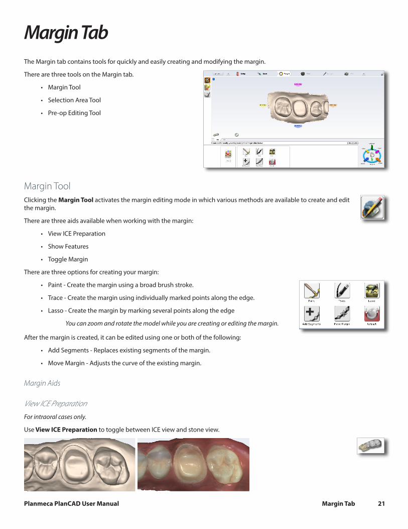
View ICE Preparation
For intraoral cases only.
Use View ICE Preparation to toggle between ICE view and stone view.

Planmeca PlanCAD User Manual Margin Tab 22
Show Features
Click Show Features to highlight high contour areas in green. This can be helpful in finding the margin edge on supragingival preps, inlays, and onlays.
Creating the MarginWhen creating the margin, use either the Paint, Trace, OR Lasso tool. They are not used in combination.
Paint tool
The Paint tool is recommended for supragingival margins.
1 Click the Paint tool.
The pointer changes to .
2 Hold down the mouse button and drag the Paint tool around the scanned prep to highlight the outer margin edge. The margin doesn’t have to be perfect, but gaps must be avoided.
3 Click the Paint button again.
The system automatically draws the margin.
4 To delete the margin and start over, click the Paint, Trace, or Lasso button.
Trace tool
The Trace tool can be used on any margin, but it is especially recommended for equigingival and subgingival margins.
1 Click the Trace button.
The pointer changes to .
2 Click Show Features to highlight high contour areas in green.
3 Zoom in and rotate the model until there is a good view of the margin.
4 Position the Trace tool in the middle of the green high contour indication on the margin.
Show Features is recommended as an aid in finding the edge of the margin, it is not necessary for using the Trace tool. Draw the margin in the middle of the green high contour indication.
5 Click on the margin. A dot appears as the starting point.
6 There are two options when drawing the margin with Trace.
• Click along the margin in small increments. The system creates straight lines between each click.
• Hold down the left mouse button to draw a continuous line. Release the mouse at any time to stop. This requires a steady drawing hand with the mouse and is not recommended for beginners.

Planmeca PlanCAD User Manual Margin Tab 23
If desired, switch between small clicks and continuous lines.
7 Click the starting point to finish the margin. The system automatically changes the trace line to a margin line.
Your margin should resemble the following.
8 To delete the margin and start over, click the Paint, Trace, or Lasso button.
Lasso tool
The Lasso tool is recommended for partial restorations and supragingival margins with a sharp edge.
1 Click the Lasso button.
The pointer changes to .
2 Click along the margin at large intervals. The system creates a line along the edge between each click.
The starting point and the most recent point clicked appear as blue dots.
3 Click to accept the previewed segment. Click the starting blue dot to finish the margin.
4 To delete the margin and start over, click the Paint, Trace, or Lasso button.
If Lasso is having trouble finding the margin, you can change the ICE Margin Mode to Texture Only. See below.
Margin Tab Settings
ICE Margin Mode
For intraoral cases only.
ICE Margin Mode determines which view the system uses to create the margin curve when using the Lasso tool.
1 Click Settings.
2 Click ICE Margin Mode.
The default setting, Normal, means that the system uses both the stone and ICE view to determine where the Lasso line should appear.
3 Select Texture only to indicate that the system should ignore the stone model and focus on the differences in the ICE view. If View ICE Preparation is deactivated, this setting returns to Normal mode.
4 Click Save to save the change or Cancel to exit without saving.

Planmeca PlanCAD User Manual Margin Tab 24
Modifying the MarginThe Margin tab provides two tools for modifying an existing margin path: Move Margin and Add Segments.
Before selecting a tool, enlarge and position the model to ensure an optimal view of the margin area. You can use either tool or both sequentially, they do not remove previous changes when clicked like the margin drawing tools.
Toggle Margin
Once the margin is created, Toggle Margin shows or hides the margin. This is helpful in verifying the margin has been drawn correctly.
Move Margin tool
Use the Move Margin tool to drag and drop a section of the margin into a new position.
1 Click the Move Margin button.
2 Position the pointer on the margin; click and hold down the mouse button.
Area of Influence - Change the tool’s area of influence by dragging the yellow button to increase or decrease the size of the ellipse.
3 Drag the margin onto the margin shelf and release the mouse button.
The system automatically redraws the margin in the new location.
4 Repeat as needed.
Add Segments tool
Use the Add Segments tool to redraw a portion of the margin.
1 Click the Add Segments button.
2 Start by clicking on a portion of the margin line that is acceptable. Then, click to add new points across the gap in the line. A line traces where you click. Use multiple clicks to create a curve.
3 Click Add Segments. The system redraws the margin and removes the unacceptable section.
4 Repeat as needed.

Planmeca PlanCAD User Manual Margin Tab 25
RetractUse the Retract tool on STL export cases with a subgingival or equigingival margin. This tool ditches the 3D model since the margin line does not convert to STL.
ICE View is not converted to STL format and cannot be used as a visual aid by the recipient of your case.
Without virtual ditching, the margin may be difficult for your recipient to see.
1 After the margin has been drawn and edited, click Retract.
The system virtually removes part of the model outside of the drawn margin.
Margin drawn - No ditching Margin drawn - With ditching
Any changes to the margin will require the ditching to be redone. If you are doing a multiple restoration case, finish all of the margin edits before using the Retract tool.
2 Click Toggle Margin to view the ditched area without the margin. This is similar to what your STL recipient will see.
3 Click Toggle Retraction to show/hide the virtual ditching.
Multiple RestorationsOn multiple restoration cases, the tooth number is assigned to each preparation when the margin is drawn.
1 Click the desired tooth number tab.
2 Draw and edit the margin for the selected tooth number.
3 Select the next tooth number.
4 Draw and edit the margin for the selected tooth number.

Planmeca PlanCAD User Manual Margin Tab 26
Drawing the margins is how the tooth number is designated for each preparation. If the wrong tooth number is selected when a margin is drawn, the margin must be marked again on the correct tooth tab.
Drawing Pontic MarginsA margin is drawn for each tooth in the bridge.
1 Click the tooth number tab for each abutment and draw the margin on the selected tooth.
An edentulous space does not technically have a margin. The margin is drawn to aid the design process.
2 Click Trace and designate the position and extension of the base of the pontic on the gingival tissue to fit the appropriate contour.
Do not go too far down the curve of the gingival tissue or you may not be able to fit the bridge in the block.
Selection Area ToolAs soon as the margin is drawn on an inlay or onlay, one of the following messages appears. If you do not want this reminder to appear in the future, select Do not show this message again.
1 Click Take me there.
The system takes you to the Selection Area screen. The Selection Area options appear at the bottom of the screen.
2 Click Add to Selection.

Planmeca PlanCAD User Manual Margin Tab 27
3 Click and drag a circle around the entire tooth. After you let go, an area is highlighted. Do not go too far beyond or short of the natural tooth or the proposal will be distorted. This process is recommended for inlays, onlays, and window prep veneers.
4 When you are satisfied with the Selection Area, click Margin Tool to edit the margin.
Remove From Selection
1 Click Remove from Selection.
2 Click and drag the mouse to select the areas that you want to remove.
3 Repeat as needed.
4 When finished, click Margin Tool.
5 Click Hide Model to view your trim region. Hide Model is only available on the Margin tab when a Selection Area has been designated.
Reset
To remove the Selection Area and start over, click Reset.

Planmeca PlanCAD User Manual Margin Tab 28
Pre-op EditingThe Pre-op Editing tool is used to designate the area of the pre-op scan that will be combined with the library tooth. This step is not necessary if the pre-op scans are being used as a template only.
1 Click Pre-op Editing.
2 To designate the pre-op library surface, use the tools at the bottom of the screen. These act the same as the margin tools.
• Trace - Removes the existing line. Draw a new pre-op area.
• Move Curve - Click to drag an exiting curve into a new position.
• Add Segments - Click to add a new line or curve to the existing area.
Trace
1 Click Trace.
2 Click or drag the mouse around the edges of the pre-op to designate the area that you want to combine with the library tooth.
Be sure to only designate areas with good data.
Down to the near the gingival tissue
Occlusal cap only Partial tooth - often used when original anatomy is chipped
3 Click on the blue dot to finish the pre-op area. The software automatically changes the trace line to a margin line.
Move Curve
1 Click Move Curve.
2 Click and drag the curve into the desired position.
3 Release the mouse button to view the new occlusal area line.
Add Segments
1 Click Add Segments.
2 Start by clicking on the portion of the line that is good. Then, click to add new node points across the gap in the line. A black line traces where you click. Use multiple clicks to create a curve.
3 Click Add Segments. The system redraws the pre-op area line and removes the bad section.
4 Repeat as needed.
Contralateral
Click Contralateral to designate this as anatomy that has to be flipped. See “4 Repeat as needed.” on page 28 for more information.

Planmeca PlanCAD User Manual Plan Screen 29
Plan ScreenThe Plan screen is used to size and position the proposal to aid autogenesis.
Preview library teeth display on the model. The bright green tooth is the active selection.
This step does not replace the Orientation function. If a preview tooth is drastically out of alignment, return to the margin screen and adjust the orientation.
1 Click a tooth tab number to select it.
2 Click the desired action button: Rotate, Resize, or Move. Place the cursor over the proposal, then right click and drag to perform the desired action.
Keyboard shortcuts are available for the resize action. Hold down the shortcut key while using the mouse: Shift for mesial/distal, Ctrl for lingual/buccal, and Alt for occlusal/gingival. Use these shortcuts carefully to avoid distorting the anatomy.
3 Click the View Bite Registration icon to view the opposing information if desired.
4 Adjust the preview tooth as needed for all proposals.
Note: In the example, Tooth 14 (2-6 ISO) is an onlay.
Autogenesis uses the adjusted preview tooth’s size and position as the new starting point for the proposal design.
5 Proceed to the Design tab.

Planmeca PlanCAD User Manual Designing the Restoration 30
Designing the RestorationAfter you have scanned the preparation and defined the margin, the Design tab provides an array of tools and options to customize the proposal.
Select from the design tools on the left menu, each of which provides additional options in the box below the restoration:
• Tooth Libraries
• Spacer Tool
• Incremental Change Tools
• Freeform Change Tools
• Contact Refinement
Tooth LibrariesOn the Design tab, the system defaults to the Tooth Libraries page. You can change the tooth library that was selected on the Setup tab. This may be useful to find a better match with the actual anatomy. You can also change the anatomy levels and/or deactivate Autogenesis for this restoration.
The library thumbnails appear in the Options box below the restoration. A green preview tooth display. The selected library is highlighted in yellow.
Select a Library
If desired, click another library to view the preview tooth. Select the library with the closest anatomy.
Anatomy Levels
The anatomy levels enable you to deactivate Autogenesis and/or select different anatomy details for this proposal. Most restorations will use the default settings.
The line on the Detail slider represents the maximum amount of detail that can be milled into the restoration.
6 If desired, use the sliders to change the amount of Detail, Slope, and/or Wear.
7 To deactivate Autogenesis, clear Autogenesis.
Contralateral
In a multiple unit case, you can select the Contralateral checkbox to indicate that you want to duplicate another designed proposal. See “Contralateral Tooth Copy” on page 41 for more information.

Planmeca PlanCAD User Manual Designing the Restoration 31
Apply the changes
Click Apply if any changes have been made to the library, Autogenesis activation, or anatomy levels.
Pre-op as Library Tooth
When Pre-op is selected as the Library tooth, Autogenesis combines the Pre-op selection with the Library A tooth. Use the following steps to move or resize the Library A tooth to modify the proposal, if desired.
1 Click Tooth Libraries.
The Pre-op selection preview displays as green. Library A tooth displays as dark red.
Move and/or resize the library tooth to be a closer match to the Pre-op selection.
2 Click Apply and repeat as needed.
Viewing OptionsThe Design tab contains additional viewing options to aid in optimizing the design that appear below and to the right of the restoration. These functions can be used with most of the tools listed above.
Hide Model
Click to show or hide the adjacent teeth. This is especially helpful when adjusting the contact area.
When Hide Model is activated on partial restorations, the area that remains is the area that was designated as the Selection Area. Rotate the proposal. Depending on the designated selection area, you may see holes. These are usually not a deterrent to the design process. If desired, return to the Margin tab and edit the Selection Area.
Material Thickness
Clicking Material Thickness alternately shows and hides the material thickness indicators in the Design tab.

Planmeca PlanCAD User Manual Designing the Restoration 32
When Material Thickness mode is active, the system colors the proposal based upon material thickness at each point on the restoration and displays a legend to indicate the thickness associated with each color.
For Your Information
The thickness shown represents the shortest distance to the preparation (green line) and not necessarily the vertical thickness at that point (red line).
Use Slice Place and the measuring grid to calculate the thickness of other areas.
Measure
Click the Measure button and click anywhere on the proposal to see the material thickness measurement displayed in the information bar.
Measure does not have to be used with Material Thickness.
View Contacts
Clicking View Contacts alternately shows and hides the strength of contact between the restoration model and adjacent dentition. Use Hide Model to remove the adjacent dentition from view.
When View Contacts is active, the system colors the proposal based upon contact strength at each point on the restoration and displays a legend to indicate the measurement associated with each color.
Slice Plane
Slice Plane enables you to view the restoration along various cross sections. This is especially helpful in optimizing material thickness and contacts.

Planmeca PlanCAD User Manual Designing the Restoration 33
Each time you click Slice Plane, you see a different cross section.
Rotate the image to see the cross section.
The Slice Plane button shows the measurement represented by the grid lines. Zoom in or out to change the measurement. Zooming in decreases the measurement. Zoom out increases it.
View Bite Registration, Opposing Model, or Pre-op
If a bite registration, opposing model, or pre-op was scanned, it can be viewed anytime during the designing process.
1 Click View Pre-op or View Bite Registration. Click View Bite Registration to view the opposing model.
2 The pre-op (yellow) or bite registration/opposing model (blue) template appears on top of the restoration.
Pre-op Bite Registration Opposing Model
To make the template translucent, click View Pre-op or View Bite Registration again. Use the slider to adjust the transparency of the template.
3 Use the pre-op, bite registration, or opposing model to aid in your design of the restoration’s anatomy.
4 Click again to remove the template from view.
Planmeca PlanCAD User Manual Designing the Restoration 34
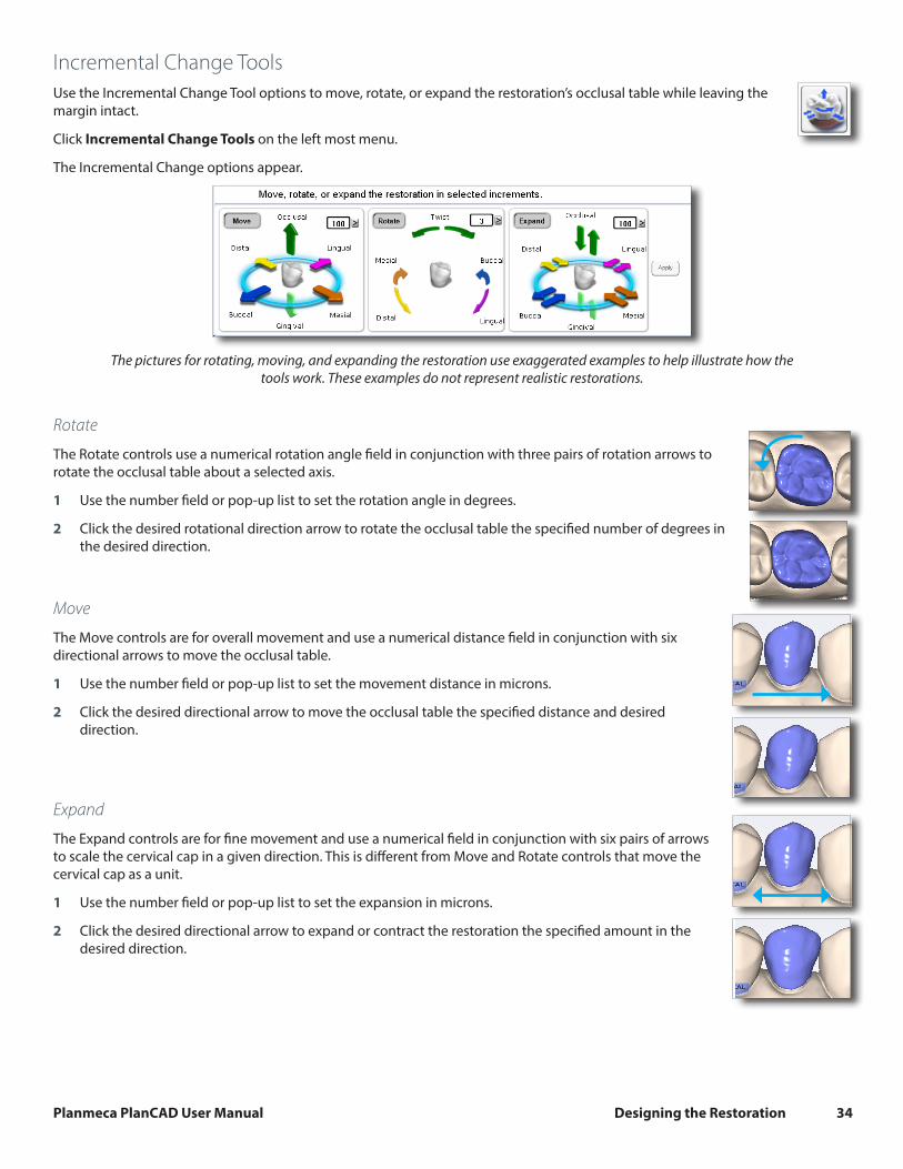
Incremental Change ToolsUse the Incremental Change Tool options to move, rotate, or expand the restoration’s occlusal table while leaving the margin intact.
Click Incremental Change Tools on the left most menu.
The Incremental Change options appear.
The pictures for rotating, moving, and expanding the restoration use exaggerated examples to help illustrate how the tools work. These examples do not represent realistic restorations.
Rotate
The Rotate controls use a numerical rotation angle field in conjunction with three pairs of rotation arrows to rotate the occlusal table about a selected axis.
1 Use the number field or pop-up list to set the rotation angle in degrees.
2 Click the desired rotational direction arrow to rotate the occlusal table the specified number of degrees in the desired direction.
Move
The Move controls are for overall movement and use a numerical distance field in conjunction with six directional arrows to move the occlusal table.
1 Use the number field or pop-up list to set the movement distance in microns.
2 Click the desired directional arrow to move the occlusal table the specified distance and desired direction.
Expand
The Expand controls are for fine movement and use a numerical field in conjunction with six pairs of arrows to scale the cervical cap in a given direction. This is different from Move and Rotate controls that move the cervical cap as a unit.
1 Use the number field or pop-up list to set the expansion in microns.
2 Click the desired directional arrow to expand or contract the restoration the specified amount in the desired direction.

Planmeca PlanCAD User Manual Designing the Restoration 35
Freeform Change ToolsThe Freeform Change Tools options enable you to modify the restoration in an unrestricted manner rather than the defined increments of the Incremental Change tools.
The pictures in this section use exaggerated examples to help illustrate how the tools work. These examples are not realistic restorations.
Area of Influence - Change the tool’s area of influence by dragging the yellow button to increase or decrease the size of the ellipse.
1 Click Freeform Change Tools on the left most menu.
The Freeform Change options appear.
• Rubber Tooth
• Dropper
• Move Cusp
• Smooth Surface
• Move Margin
• Define Feature
Rubber Tooth
Use the Rubber Tooth tool to change the form of the restoration by pushing or pulling inward or outward on the restoration. In this example, the tooth was pulled in the direction of the arrow.
1 Click the Rubber Tooth tool.
2 Click and hold down the left mouse button on the part of the restoration that you want to change. The area that will be affected turns pink.
3 While holding down the left mouse button, drag the cursor in the direction that you want the restoration to move.
Small moves are recommended. Exaggerated example shown. Rotate and zoom as needed to view the changes.
4 Click Undo to remove changes.
Planmeca PlanCAD User Manual Designing the Restoration 36
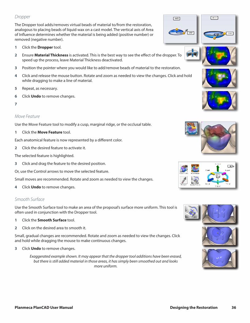
Dropper
The Dropper tool adds/removes virtual beads of material to/from the restoration, analogous to placing beads of liquid wax on a cast model. The vertical axis of Area of Influence determines whether the material is being added (positive number) or removed (negative number).
1 Click the Dropper tool.
2 Ensure Material Thickness is activated. This is the best way to see the effect of the dropper. To speed up the process, leave Material Thickness deactivated.
3 Position the pointer where you would like to add/remove beads of material to the restoration.
4 Click and release the mouse button. Rotate and zoom as needed to view the changes. Click and hold while dragging to make a line of material.
5 Repeat, as necessary.
6 Click Undo to remove changes.
7
Move Feature
Use the Move Feature tool to modify a cusp, marginal ridge, or the occlusal table.
1 Click the Move Feature tool.
Each anatomical feature is now represented by a different color.
2 Click the desired feature to activate it.
The selected feature is highlighted.
3 Click and drag the feature to the desired position.
Or, use the Control arrows to move the selected feature.
Small moves are recommended. Rotate and zoom as needed to view the changes.
4 Click Undo to remove changes.
Smooth Surface
Use the Smooth Surface tool to make an area of the proposal’s surface more uniform. This tool is often used in conjunction with the Dropper tool.
1 Click the Smooth Surface tool.
2 Click on the desired area to smooth it.
Small, gradual changes are recommended. Rotate and zoom as needed to view the changes. Click and hold while dragging the mouse to make continuous changes.
3 Click Undo to remove changes.
Exaggerated example shown. It may appear that the dropper tool additions have been erased, but there is still added material in those areas, it has simply been smoothed out and looks
more uniform.

Planmeca PlanCAD User Manual Designing the Restoration 37
Move Margin
The Move Margin tool on the Design tab allows you to make minor margin adjustments without losing the design work.
1 Click the Move Margin tool.
The restoration becomes translucent.
2 Position the pointer on the margin line.
3 Click and hold down the mouse button.
4 Drag the margin into the new position and release the mouse button.
The system automatically redraws the margin in the new location.
5 Click the Move Margin tool to see the solid restoration view.
Define Feature
Use Define Feature to add anatomical features to the restoration. Multiple features can be drawn and moved simultaneously.
1 Click Define Feature and trace the feature on the restoration proposal.
2 Use the arrow controls to move the feature line(s) in the desired direction.
As an alternative, use the Rubber Tooth to pull or push the feature to the desired position or shape.
Paint Feature
Use Paint Feature to designate an area of the proposal that you want to move. This is often used to designate a contact area that you want to move.
1 Click Paint Feature and paint the desired area of the proposal.
2 Use the arrow controls to move the highlighted area in the desired direction.
As an alternative, use the Rubber Tooth to pull or push the feature to the desired position or shape.

Planmeca PlanCAD User Manual Designing the Restoration 38
Contact RefinementContact Refinement enables you to set the strength of the occlusal and/or interproximal contacts. It also enables you to broaden the interproximal contacts by making the proposal more square.
1 Select the desired Strength for the Bite and/or Contacts.
2 There are two ways to make the adjustment to the selected strength.
• Click Refine to automatically change the occlusal table or the interproximal contacts.
• Circle the desired area.
Another way to change the interproximal contacts is to make the proposal more square.
3 Click Occlusal in View Controls.
4 Click Broaden Distally and/or Broaden Mesially to make the proposal more square. This will usually be utilized on posterior crowns.
The Broaden buttons change the proposal in set increments. It is not connected to the selected Strength.
Be careful when using this feature. Overuse will make the proposal too square. See the exaggerated example below.
5 Click Undo or reapply the library tooth to remove the changes if desired.

Planmeca PlanCAD User Manual Designing the Restoration 39
Spacer ToolYou may use the Spacer Tool to override the default spacer thickness and margin ramp values.
Spacer thickness is the space between the restoration and the preparation. The tool has separate settings for the axial and occlusal walls.
Margin ramp is the contact zone for the margin.
Use the sliders or pop-up menus to change the values.
Bridge Spacer Settings
The default Spacer Tool settings are different on bridges to account for the larger Path of Insertion.
The normal maximum for the spacer is 0.20 mm. On bridge cases, the spacer defaults to 0.20 mm and can be increased to 0.30 mm.
A larger default margin ramp of 1 mm is used to aid in stability.
Design Tab SettingsClick Settings to select which features Autogenesis uses, to enter the default Bite and Contact Strengths, and to use Margin Boost.
Autogenesis Settings
Each type of restoration has the option of different settings.
Select which settings you desire for each restoration type.

Planmeca PlanCAD User Manual Designing the Restoration 40
Contact Strengths
Contact Strengths designates the default strength of the Proximal Contact and Occlusal Contact in Autogenesis and Contact Refinement.
For Your Information
Autogenesis may not create an interproximal contact if the proposal makes contact with gingival tissue, as illustrated in the example below.
In these cases, you must create the contact manually.
Margin Boost
Margin Boost setting enables clinical operators to increase the thickness of the proposal around the margin. Margin Boost is OFF by default.
Use Margin Boost Settings to designate the default margin boost for each restoration type.
The controls are similar to the Dropper tool. The Area of Influence (blue bubble) affects the width and thickness of material added. The width is represented by the horizontal arrow, 1.000 in the example. The thickness of material is represented by the vertical arrow, 0.100 in the example. The vertical slider on the right is the height of the material added. This is generally kept towards the bottom, near the margin.
This tool can be used on all cases to ensure sufficient material thickness and avoid chipping during milling.
Make any desired changes to the Margin Boost. In Tooth Libraries, click Apply to regenerate the proposal with the new settings.
The settings are saved for the next proposal.
Note: Margin Boost is recommended over the use of Margin Thickness.

Planmeca PlanCAD User Manual Designing the Restoration 41
Designing MultiplesOn cases with multiple proposals, click the desired tooth number tab to designate which tooth is being designed.
The ALL tab enables certain design tools to manipulate every proposal at the same time or activates all proposals at the same time to enable individual manipulation without switching tooth tabs.
Manipulate ALL proposals at the same time
Manipulate individual proposals without switching tabs
Incremental Change Tools
• Move • Rotate • Expand
Freeform Change Tools
• Rubber Tooth • Dropper • Smooth Surface
When using the Incremental Change tools, The margins do not adjust to the new position until Apply is clicked or another tool is selected.
Contralateral Tooth CopyCopy existing contralateral dentition onto the prep or copy a designed restoration onto the prep.
Copy Contralateral Dentition
1 Use the Scan Pre-op Scan Type and capture the prep and the desired contralateral dentition. (Note: Use the Scan Swap feature if you accidentally skip this step.)
2 Use the Time Saver function to copy the pre-op model as the prep model or scan the prep and proximal dentition again.
3 Scan the Opposing and Buccal with the normal procedure.
4 Set the Orientation and mark the Margin.
5 Click Pre-Op Editing and designate the anatomy of the contralateral dentition that you want to copy.

Planmeca PlanCAD User Manual Designing the Restoration 42
6 Click the Contralateral checkbox.
7 Proceed to the Plan tab and adjust the position of the contralateral shell to match the placement and alignment of the preparation.
8 Proceed to the Design tab. The contralateral pre-op anatomy is mirrored and acts like a normal pre-op case.
Copy a Restoration Design
1 Follow the normal scan, orientation, and margin draw workflow for both preparations.
2 Fully plan and design the first restoration proposal.
3 Click the second tooth tab.
4 On the Tooth Libraries screen, click the Contralateral button to designate that you want to copy the other design. (This only appears after the first tooth is designed.)
5 Proceed with the normal design workflow.
Note: Any changes on the Plan tab for the second tooth is ignored when a design is being copied. The position of the contralateral design is based on the Orientation of both preparations. Ensure you have good orientations for both
tooth numbers.

Planmeca PlanCAD User Manual Mill Tab 43
Mill TabOn the Mill tab of the design software:
• select a block
• choose location for the sprue
• position for the restoration in a multiblock
• specify tool path settings (standards vs detailed)
• view mill simulation
• send the design data to the mill
At the mill, you will load the block, ensure the milling tools are in place, verify the fluid is at the correct level, and then start the mill process.
If you are exporting your case, proceed to the Export chapter.
Setting up the restoration for millingFinal restoration setup is done on the Mill tab.
Yellow or red shading on the restoration indicates the material in the shaded area is thin and the material manufacturer recommends adjustment. Return to the Design tab to make changes in material thickness.
Click the View Model icon to view or hide the preparation and proximals, if desired.
Select a Block Size
Available block sizes are listed in the Blocks section. A default size is selected. Click on another size if desired. If the restoration will not fit into any of the block sizes available in the chosen material, click Settings to select a different material.

Planmeca PlanCAD User Manual Mill Tab 44
Sprue Placement
Change the location of the sprue on the restoration, if desired, by moving the placement indicator (circled in orange below) along the circle that represents the exterior of the restoration or by clicking one of the arrows. Recommended locations are as follows.
• Anteriors/posteriors: midway between lingual and the mesial or distal
• Premolars: mesial or distal
• Inlays and Onlays: largest proximal box
Restoration
Sprue
Mandrel
The sprue is the connection between the restoration and the mandrel.
Rotate and inspect the restoration to ensure the sprue is not positioned on a groove. Move the sprue towards a flatter area of the restoration. This is usually near the interproximal, but should not be put on the contact area unless it is necessary. It must be a full round sprue, at an angle never straight buccal and never straight lingual . Placed away from the margin. If you need a smaller block option try a straight inter-proximal placement
High, away from margin and contact areas.
Take care in positioning the sprue on inlay and onlay restorations. Ensure the sprue is not attached to an upper surface unless it is an occlusal only inlay. If the sprue appears to be missing, then it is on an interior surface. Try moving the sprue to a new position. Do not mil a partial sprue if another position with full sprue is available. Your orientation affects the position of the sprue.
No sprue visible - it is on the interior surface. Change the position of the
sprue.
Partial sprue - Change position to allow a full sprue when possible.
Restoration Positioning
When using a multiblock, the Restoration Positioning arrows are enabled. Use the arrows to move the restoration up or down within the block to achieve the desired shading. Be aware that if the restoration is near the top or bottom of the block, extra milling time will be required to remove the extra material.

Planmeca PlanCAD User Manual Mill Tab 45
Mill Simulation
The Simulation Mode portrays the milled restoration. It takes about 10 seconds to generate and is recommended before milling to check the internal fit.
If a hang-up is seen, you can increase the spacer or make any other necessary design changes.
1 On the Mill tab, click Sim (located under Send to Mill).
2 Confirm the desired setting:
• Standard is recommended for full coverage restorations.• Detailed is recommended for partial coverage restorations.
3 Click OK.
The system takes a few seconds to create the simulation.
IPS e.max ZirCAD Simulation and Milling
There are a few differences to be aware of on the Mill screen when simulating IPS e.max ZirCAD.
A reminder appears as you enter the screen - Perform a Sim to ensure inner surfaces are cleared out. For bridges, ensure connectors are above minimum area requirements for strength. Click OK to continue.
Detailed milling is the only option when using this material.
For Planmeca PlanMill 40 users, you must check the This case will be milled on a PlanMill 40 (not “S” model) checkbox when you do a simulation. Using this checkbox affects the simulation only, not the milling toolpath. If you have an older model mill that does not specify the model underneath the touch screen, then you will want to activate this checkbox. If you are unsure of which model that you have, please call Customer Support at 800-537-6070 (Option 2).
See your mill user manual for further details about milling zirconia.
Evaluate the simulation
• Are there hangups? Hangups are areas where the tools cannot completely remove the material for the interior of the proposal.
• Is there overmilling? Overmilling is caused by areas of the preparation that are smaller than the tools. The tools must “overmill” and remove extra material so that there is no hangup. Is the overmilling drastic enough to cause a loss in retention?
1 Click Hide/View Model and click the Gingival arrow to view the interior aspect of the proposal.
The simulation will show swirl marks in areas where the milling tools have to overcompensate for small prep areas.
Sharp areas of the preparation that are smaller than the milling tools can result
in overmilling.
Swirl marks indicate overmilling. The rest of the proposal’s interior is
relatively smooth.

Planmeca PlanCAD User Manual Mill Tab 46
2 Click Hide/View Model to activate the model again.
3 Click Slice Plane once or twice to get the desired slice direction.
4 Drag the slice to the approximate area of the overmilling. Rotate and zoom to evaluate.
A maximum zoom of 1 mm is recommended.
Imported restoration cases do not display the model, you will only see the mill simulation.
Example A: In the example below, the majority of the spacer follows the contours of the preparation (highlighted in green). There is a section of extra spacer where the tools had to overcompensate for the sharpness of the preparation (highlighted in orange).
Example B: In the example below, there is large overmilling (orange), minor overmilling (yellow) with only a slight increase in the spacer, and on a different slice of the same proposal, there is an overlap which would cause a hangup (red).
Is there too much overmilling? How much is “too much”? What can be done about a hangup? Analyzing and fixing these issues requires judgment calls and experience. That is why we recommend calling Customer Support at 1.800.537.6070 to have them evaluate your simulation before you mill. If you mill a problematic proposal, you may have too much spacer and loss of retention or you may have hangups and have to adjust the restoration (and mill another block) or adjust the preparation.
Evaluating the Connectors on BridgesIt is important to evaluate the connections on the bridge and look for possible hangups.
The sprue will be on the mesial or distal side of the bridge.
1 Click View Model to hide the model.
2 Click Sim.
When the Simulation is run, the connections between the teeth are displayed.

Planmeca PlanCAD User Manual Mill Tab 47
3 Click Slice Plane twice.
When Slice Plane is activated on a bridge mill simulation, the system measures the slice width. If the slice is thinner than the material guidelines, the slice displays as red. It is important to slice the simulation through the thinnest part of the connectors (orange lines in the examples).
Posterior cases tend to have wider contacts with smaller embrasures and are unlikely to be thin. Anterior cases have smaller contacts and larger embrasures. Any thin area should be evaluated.
4 Move the Slice Plane to a connector. If the Slice Plane needs to be rotated to slice through the thinnest part, hold down the Ctrl key while moving the mouse to rotate.
5 Rotate the model to view the slice.
6 If the slice is red, adjust your embrasures and/or contacts and try the simulation again. Note that when the model is hidden, the Slice Plane icon displays the mm2 area.
Minimum required thickness:
• Telio CAD - 12 mm2
• IPS e.max - 16 mm2
• IPS e.max ZirCAD - 7 mm2 (anteriors), 9 mm2 (posteriors)
7 Click View Model to activate it.
8 Click the Gingival View Control arrow to view the model from underneath.
9 Look for mill simulation issues. See “Mill Simulation” on page 45 for more information. Call Customer Support for help on your first few cases of possible milling issues on bridges.

Planmeca PlanCAD User Manual Mill Tab 48
Send to Mill1 Click Send to Mill when you are satisfied with the restoration and mill set up.
2 If you have multiple mills, select the desired mill from the list. See “Mill Network Settings” on page 48 for how to create/edit this list. Use the Favorite button to designate the highlighted mill as the default. The favorite mill is always at the top of the list.
3 Confirm the desired Milling Mode.
• Standard is recommended for full coverage restorations.
• Detailed is recommended for partial coverage restorations.
Detailed mode is not recommended for e.max c14 blocks and may result in broken tools.
Crown Bridges Inlay Onlay Veneer
I-12 Detailed
Standard
Detailed
C-14 Standard
N/AC-16 Standard
IPS e.max ZirCAD Detailed Detailed
Mill Tab SettingsClick Settings to change any of the settings listed below.
Mill Network Settings
Use this screen to edit the list of available mills. See “Mill Network Settings” on page 48 for details.
Material/Shade Settings
The material and shade for the current restoration can be changed here.
Margin Thickness Settings
Select the minimum material thickness along the margin. The recommended margin thickness is 70 to 100 microns to reduce margin chipping or potential short margins.
Milling Settings
Milling Settings only affect proposals with a sharp interior angle, like an anterior incisal edge. If the interior of the proposal is smaller at the tip than the tools in the mill, the Standard setting removes extra material at the tip. This may lead to a crown that is too thin at the top. The options are to round the preparation or to select Undermill. If Undermill is selected, then the mill will go as far as the tool’s size will allow and the remainder must be removed manually.
1
2
3
1
4
3
Proposal
Standard
Preparations
Undermill

Planmeca PlanCAD User Manual Mill Tab 49
Simulation Settings
Click Settings on the Mill tab to view/edit the Simulation Settings. The default selection is Speed. This will give you a faster simulation. Select Quality for a more accurate simulation, but be aware that it will take longer to process. Note that when the design software is restarted, it will return to the default Speed setting.
Mill time is displayed in the information when Quality simulations are processed.
Troubleshooting• On the Mill tab, Multiblocks appear to be embedded in the block. This is a visual issue only.. Simulation and actual milling
are correct.
• Model Sharpness may cause scanning to be slower. If this happens, try a lower setting or try scanning the majority of the information in a low setting and then erase and capture the problem area in a higher sharpness setting. Higher settings use extra filtering.
• HD Snapshot may accidentally be used at the same time as Active Delete (or any other time that you are hovering). If this causes an issue with coloring on the model, simply deactivate the Apply to ICE option.

Planmeca PlanCAD User Manual Exporting Data 50
Exporting DataThe screenshots in this chapter are not created by E4D Technologies and may have changed since this manual was
published. Please see the Romexis User Manual or www.planmeca.com for more information on Romexis.
There are several methods for sharing digital information using Romexis.
• CAD/CAM cases can be transferred between other Planmeca or E4D systems.
• STL files of CAD/CAM data can be exported as 3D Models to and from an external source.
• View images on an iOS device with iRomexis installed. See Romexis manual for more information.
• Securely send cases over the internet using Planmeca Romexis Cloud services (see Romexis manual) or send to a lab through DDX.
Exporting a CAD/CAM Case1 To export a file to share with another Planmeca system, click File - Export - Export CAD/CAM Case.
2 Select the destination folder and enter a file name. Click Save.
Exporting 3D Models
3D Model Export
To export 3D models in STL format click the case in the Patient’s Case Files list then 3D model export.
1 Navigate to the desired destination folder. It is recommended to create a new folder on the desktop to easily find the files later.
2 Click Save
For equigingival or subgingival margins, ensure you have used the Retract margin tool. The drawn margin is not saved and the STL recipient will not be able to use ICE View to find the margin. See “Retract” on page 25.
DDX ExportTo send CAD/CAM or STL models via the DDX network to registered DDX Labs. See Romexis User Manual for configuration instructions.
The recipient can import the STL files or the entire cad/cam case if they have our design software.
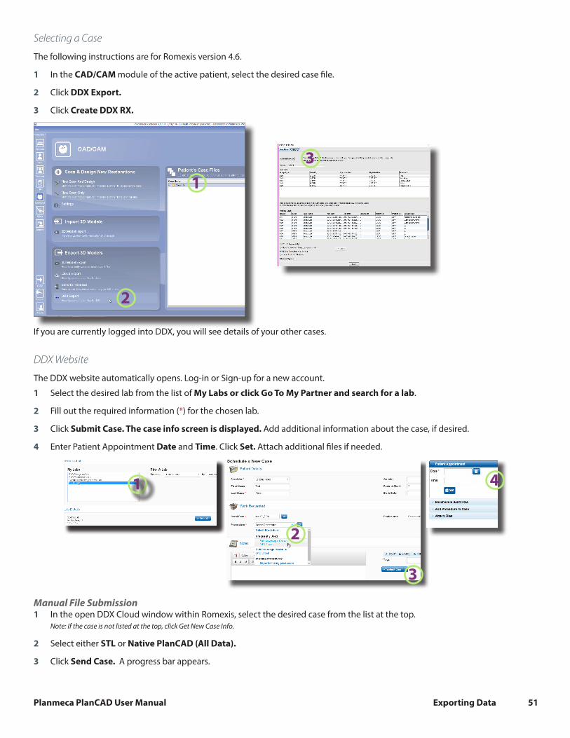
Planmeca PlanCAD User Manual Exporting Data 51
Selecting a Case
The following instructions are for Romexis version 4.6.
1 In the CAD/CAM module of the active patient, select the desired case file.
2 Click DDX Export.
3 Click Create DDX RX.
1
2
If you are currently logged into DDX, you will see details of your other cases.
DDX Website
The DDX website automatically opens. Log-in or Sign-up for a new account.
1 Select the desired lab from the list of My Labs or click Go To My Partner and search for a lab.
2 Fill out the required information (*) for the chosen lab.
3 Click Submit Case. The case info screen is displayed. Add additional information about the case, if desired.
4 Enter Patient Appointment Date and Time. Click Set. Attach additional files if needed.
1
2
3
4
Manual File Submission1 In the open DDX Cloud window within Romexis, select the desired case from the list at the top.
Note: If the case is not listed at the top, click Get New Case Info.
2 Select either STL or Native PlanCAD (All Data).
3 Click Send Case. A progress bar appears.
3

Planmeca PlanCAD User Manual Exporting Data 52
4 A message appears when the upload is complete. Click Continue to exit.
1
2 3
An upload progress bar appears. Progress is shown as a blue bar on a red background.
4