plane(u lehigh 1/1 unclassifiled eheohheemomei fig
TRANSCRIPT

AD-A137 37 QUASI-CLEAVAGE AND MARTENSITE HABIT PLANE(U LEHIGH 1/1UNIV BETHLEHEM PA NS OF FRACTURE AND SOLID MECHANICSMGAO ET AL SEP 83 ISM-83122 NOVO 4-75-C 0543
UNCLASSIFIlED FIG 11/6 N
EhEohhEEmomEI
soflflflumum

1.6.
l~lKA ILO|Lam
MICROCOPY RESOLUTION TEST CHARTNATIONAL BUREAU OF STANDARDS-I963-A

tJ I
4 41

QUASI-CLEAVAGE AND MARTENSITE HABIT PLANE
by__ _ _ _ _ _ _ _ _
Accession For
M~ing Gao1 and R. p. Wei 2 NTIS G <.t&I
Lehigh University DTIC TAB
Bethlehem, PA 18015 Jnenncvin iid sdJustificaltion_____
Dlistribution/_
Availability CodejAvail and/or
Dist Special
Technical Report No. 16 Ai -
OFFICE OF NAVAL 1RESEP: CH
This document has been approved for public release andsale; its distribution is unlimited.
Visiting Scholar, Department of Metallurgy and MaterialsEngineering; on leave from the Department of MaterialsSciences, Shanghai Jiao Tong University, Shanghai,People's Republic of China.
2Professor of Mechanics, Department of MechanicalEngineering and Mechanics.

UnclassifiedSCURTY CLASSFICATION OF THIS PAGE (Wi.. ot.ge .j __________READ __INSTRUCTIONS
REPORT DOCUMENTATION PAGE BEPORK COMPLETIG FORMI. REPOT NUMBE GOVT ACCESSION NO IL RECIPICNT'S CATALOG NUMBER
QU S!-CLEVAGE AMD HATENSITEHAITehiaRpotN.1
Ming Gao and R. P. weiCotatN01-5-
3. PERFORMING ORGANIZATION NAME AND ADDRESS 10. PROGRAM ELEMENT. PROJECT, TASK
Lehigh University AREA & WORK UNIT NUMBERS
Bethlehem, PA 18015 NR 036-997
11I. CONTROLLING OFFICE NAME AND ADDRESS 12. REPORT DATE
Of fice of Naval Research September, 1983Department of the Navy 13. NUMBER OF PAGES
Arlington, VA3914I. MONITORING AGENCY NAMIE A ADDRIESS4If dUieent from Cionln Office) 15. SECURITY CLASS. (of this report)
Unclassified154L DCCL SSIFICATION/ DOWNGRADING
SCM bLE
16. DISTRIBUTION STATEMENT (of eti Report)
This document has been approved for public release and sale;its distribution is unlimited.
17. DISTRIBUTION STATEMENT (of thme abeerect stiorod in Block"2. If Eforea'e **a Rem)
Is. SUPPLEMENTARY NOTES
Is. KEY WORDS (Continue on reveresd it* If aecoe d UdeeIUIp oc ek numbe)
Fracture mechanics, fractography, steels, hydrogen embrittlement,microstructure, crystallography.
2S.N 111TRACT rcauMuNmm 41 MvWd @#do It 01040p. m m gn Or Week 01110im)
Quasi-cleavage (QC) is often observed on the fracture sur-faces of hydrogen exnbrittled iron and steels. For quenched-and-tempered martensitic high strength steels, most QC facets showgeometrical markings that are made up of fine oblong elementsarrayed at well defined angles. To better understand this modeof failure, scanning and transmission electron microscopy (SEMand TEN) and etch-pit analysis have been applied to the study of
DDO JAN" 1473 go-no olP INov "51 is ooEtEwi Unclassified011CNN &0102034ATO 1G0I 70
SBONN",UIAYO PThSPNEfu ~e~--

Unclassitied.6%.uq§IT CLASSIFICATION OF THIS PAGfWMeI DEa Entem)
quasi-cleavage and of martensitic structure in an AISI 4340 steel(teipered at 478 K). A special technique was developed for deter-mining martensite habit planes without the need for concomitantpresence of retained austenite or annealing twins in the micro-structure.
Quasi-cleavage in ;this AISI 4340 steel has been shown to becleavage along (1101v planes through martensites, and {2251'have been unambiguously determined as the martensite habit planes.The methods of analyses are described. The relationship betweensurface features of QC facets and the martensitic microstructureand the possible interaction between hydrogen and slip are dis-cussed. Potential application of the analysis method to studiesof martensitic transformation is considered.,
UnclassifiedMUMUI? CL"MA"SPCYOu OF T"15 P~AOMtS bas 3mMe

QUASI-CLEAVAGE AND MARTENSITE HABIT PLANE
Ming Gao1 and R. P. Wei2
Lehigh UniversityBethlehem, PA 18015
ABSTRACT
Quasi-cleavage (QC) is often observed on the fracture sur-faces of hydrogen embrittled iron and steels. For quenched-and-tempered martensitic high strength steels, most QC facets showgeometrical markings that are made up of fine oblong elementsarrayed at well defined angles. To better understand this modeof failure, scanning and transmission electron microscopy (SEMand TEM) and etch-pit analysis have been applied to the study ofquasi-cleavage and of martensitic structure in an AISI 4340 steel(tempered at 478 K). A special technique was developed fordetermining martensite habit planes without the need for concomi-tant presence of retained austenite or annealing twins in themicrostructure.
Quasi-cleavage in this AISI 4340 steel has been shown to becleavage along {110}9a planes through martensites, and (225)yhave been unambiguously determined as the martensite habitplanes. The methods of analyses are described. The relationshipbetween surface features of QC facets and the martensitic micro-structure and the possible interaction between hydrogen and slipare discussed. Potential application of the analysis method tostudies of martensitic transformation is considered.
1 Visiting scholar, Department of Metallurgy and MaterialsEngineering; on leave from the Department of Materials Sciences,Shanghai Jiao Tong University, Shanghai, Peoples Republic ofChina.2professor of Mechanics, Department of Mechanical Engineeringand Mechanics.
____ ___ ____ ___ ____ ___

QUASI-CLEAVAGE AND MARTENSITE HABIT PLANE
Ming Gao and R. P. WeiLehigh University
Bethlehem, PA 18015
1.0 INTRODUCTION
It is known that quasi-cleavage (QC) is one component of
hydrogen assisted cracking in steels. There are increasing
amounts of evidence to show that quasi-cleavage produced by
internal hydrogen embrittlement in iron single crystal and steels
is crystallographic and occurs on planes approximately parallel
to {1101 , or {112) , in martensite (1-8]. It has been reported
also, however, that QC in steels occurred along martensite lath
packets (9-131; notably the recent reports by Costa et al.
(10,11]. These investigators observed that the features of QC
facets in a medium carbon steel are very much like the features
of its martensite microstructure. Since the identification of
cracking path is essential to the understanding of mechanisms for
hydrogen assisted crack growth, a further study of QC is needed
to determine if it is truly cleavage, vis-A-vis cracking along
martensite lath boundaries.
In the present investigation, QC facets, produced from
earlier studies of sustained-load crack growth in an AISI 4340
steel in hydrogen and hydrogen sulfide [14-16],were examined.
Special emphasis was placed on the relationship between these
facets and the martensite microstructure. Identification of the
crystallographic orientation of QC facets was made by using an
etch-pit method. The relationship between the configuration of
* I -A

-2
fine features observed on the QC facets and martensite habit
planes was also determined. For this determination, a method for
determining the martensite habit plane in steels, in the absence
of retained austenite, had to be developed. This method is based
on the combined use of crystallographic theory of martensitc
transformation and of trace analyses of transmission electron
micrographs of martensites.
The experimental procedures and the results of fractographic
and etch-pit analyses are given first. The method for deter-
mining the martensite habit planes and its application to AISI
4340 steel are then described. The relationship between quasi-
cleavage fracture facets and the martensite microstructure is
then considered. Details of the crystallographic analysis proce-
dures are given in the appendices.
2.0 EXPERIMENTAL PROCEDURES
The AISI 4340 steel used in this study is the same one used
in the earlier studies on crack growth kinetics [14-16], and has
extra low residual impurity content. It was laboratory vacuum
melted and vacuum cast as a 100 mm thick by 305 mm wide by 560 mm
long slab ingot, and was hot rolled straight-a-way to 9 mm thick
plates. The chemical composition, heat treatment and room tem-
perature tensile properties of this steel are given in Table 1.
Specimen configuration and experimental procedures for deter-
mining the crack growth kinetics in hydrogen and hydrogen sulfide
are given in (14-16).
* 9
- *,-** ,

-3-
Fracture surfaces produced in the crack growth studies [14-
16] were examined with a scanning electron microscope (SEM)
operated in the secondary electron imaging mode at 20 kV. An
etch-pit method [17] was used to determine the crystallographic
orientation of the quasi-cleavage facets. Etching was carried
out at 298 K in an aqueous solution, containing 15 ml H202, 2 ml
HCl and 100 ml H2 0. Pits of acceptable quality were obtained
after etching for 5 to 10 seconds.
To provide further identification and correlations of the
fracture path with the underlying microstructure and martensite
habit planes, transmission electron microscopy (TEM) was used.
Thin foils were prepared by chemical thinning with a sloution of
160 ml H2 0, 30 ml H2 02 and 10 ml HF at first. Final thinning was
done by twin-jet electropolishing at 273 K and 38-40 volts (d.c.),
in an electrolyte containing 515 ml of glacial acetic acid, 100
grams of sodium chromate and 50 grams of chromic acid [18].
3.0 FRACTOGRAPHIC OBSERVATIONS AND ORIENTATION OF QC FACETS
3.1 Quasi-Cleavage Features
The quasi-cleavage facets, produced by sustained-load (Stage
II) crack growth in hydrogen and in hydrogen sulfide [14-16],
exhibited distinct geometrical markings. A typical SEM micro-
graph of a QC facet is shown in Fig. l(a), and shows the presence
of such markings at a high magnification. A SEM micrograph of a
polished-and-etched surface of this AISI 4340 steel is shown in
Fig. l(b) for comparison. It can be seen clearly from these two
micrographs that (i) the geometrical markings are made up of fine
oblong elements that are either parallel or intersect at well

-4-
defined angles, and (ii) the configuration of these elements on
the QC facets resembles the microstructure of quenched and
tempered AISI 4340 steel (specifically, that of martensite).
This resemblance between the surface features of QC facets and
the microstructure of martensitic steel was also found by Costa
and Thompson [13].
To further investigate the characteristic features of QC,
single surface trace analyses were made on six (6) facets to
determine the angles formed by the oblong elements (see Fig.
l(a)). Since these elements form triangles, only two of the
three angles (designated as A and B) for each triangle were mea-
sured and the third one (designated as C) was calculated from the
other two. The results are given in Table 2, and show the
average value of each angle to be about 600. In addition, pairs
of precisely matched micrographs were taken from mating fracture
surfaces, as illustrated in Fig. 2. From Fig. 2, it can be seen
that the geometrical markings are matched one-to-one across the
mating fracture surfaces.
It is conceivable that these oblong elements correspond to
the intersections of martensite laths with the local fracture
surface, i.e., with the QC facet. The angles between these
oblong elements would then correspond to angles between the
traces of martensite laths or plates on the local fracture sur-
face. Since the angles are approximately equal to 600, it is
reasonable to expect that quasi-cleavage occurred along specific
crystallographic planes through martensite, and that the traces
reflected the configuration of martensites with specific habit
planes in prior-austenite.
, - - . , .

-5-
3.2 Crystallographic Orientation of QC Facets
To investigate the possibility that cracking occurred along
specific crystallographic planes through martensite, an etch-pit
method was used to determine the crystallographic orientations of
the facets [8,17]. For body-centered-cubic crystals, etch pits
are produced on (100) and {1101 planes and exhibit shapes as
illustrated in Fig. 3(b). A typical example of etch pits on a QC
facet is shown in Fig. 3(a). The hexagonal shape of the pits
clearly shows that the QC facets correspond to (l10)., planes
through the martensite. This result is consistent with the
recent findings on iron single crystal and commercial alloy
steels (6,8].
Based on this identification, the angles formed by the
traces of martensite laths or plates on the {1101., planes (i.e.,
the QC facets) can be readily determined if the habit planes of
martensite are known. Information on martensite habit planes,
however, is not available for AISI 4340 steel. Recent studies
have shown that {111),, (557)y and {225} are possible habit
planes of martensite in quenched and tempered, medium carbon and
medium carbon-low alloy steels [19-21]. Calculations of angles
formed by the traces of martensite laths or plates on (119).,
showed that the observed 600 arrangement could be satisfied by
any of the three possible habit planes (see Appendix I). Another
method is needed, therefore, to complete the identification of mar-
tensite habit planes in AISI 4340 steel.
7 _ '. .II'

-6-
4.0 DETERMINATION OF MARTENSITE HABIT PLANE IN AISI 4340 STEEL
Determinations of martensite habit planes in steels are
usually made with the aid of retained austenite in the micro-
structure, which provides a link to the pre-transformation crys-
tal structure, or by the use of two-surface trace analysis (22].
Direct determination of martensite habit planes for the steel
used in this study, however, could not be made by the first
method because no retained austenite was found. It was also
difficult to use the two-surface trace analysis methods [22],
because of the extreme difficulty in finding a prior-austenite
grain that contained two distinctly different annealing twins. A
method had to be developed, therefore, for selecting martensite
habit planes from several candidates without requiring informa-
tion from retained austenite or annealing twins. This method and
its application to the analysis of AISI 4340 steel are described
in the following subsections.
4.1 Principle of the Method
If {hkl} are the martensite habit planes for a metal A and
the plane of a thin foil of this metal corresponds to a crystal-
lographic plane (uvw) in its "prior-austenite" lattice, then the
trace directions of {hkl} 7 on (uvw) and the angles formed by
these traces can be readily calculated by using the zone law and
the corresponding direction cosines (see Appendix I). The
results should be unique for a specific system of habit planes.
Since martensite laths or plates lie in the habit planes, these
traces and angles should correspond to those of martensite in the
thin foil, i.e., in the (uvw)Y plane.

-7-
The (uvw) plane, however, is no longer accessible after theY
metal transforms completely from the parent austenite to the
product martensite. Only the martensite planes that are parallel
to the original plane (uvw) can be determined from selected areaY
diffraction analysis of the transformed microstructure. Thus, if
one can determine the original thin-foil plane, (uvw)7, in the
"prior-austenite" lattice from these martensite planes, the mar-
tensite habit planes then can be determined from the measurements
of angles between martensite traces on the thin foil. Such a
transformation of martensite planes into its original austenite
planes can be made by using the (M/A) matrices. These matrices
can be derived from crystallographic relationships, such as the
Kurdjumov-Sachs relationships (21,231, and recognize that marten-
site transformation involves shear deformation on a common slip
plane in a given "prior-austenite" grain.
Because the analysis involves two or more martensite
plates in a given foil and of the permissible freedom in indexing
diffraction patterns, unique identification of a specific set of
martensite habit planes requires the consideration of the crys-
tallographic relationships between individual martensite plates
in a given "prior-austenite" grain in the foil. The procedures
for these analyses are outlined in the following subsection and
are applied to the study of AISI 4340 steel subsequently.

-8-
4.2 Procedures
Based on the principles described above, the procedures for
determining the martensite habit planes from candidate planes are
as follows:
(1) Find a region of the thin foil where three sets of
martensite plates intersect to form triangles (for
example, as in Fig. 4(a)).
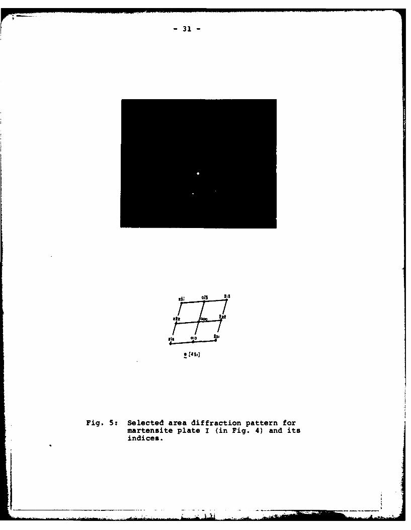
(2) Obtain selected area diffraction (SAD) patterns for
each set of plates at a fixed foil orientation; usually
perpendicular to the axis of the incident electron
beam. (See Fig. 4(b), for example).
(3) Determine the beam direction, or foil plane normal,
relative to the martensite structure from the SAD pat-
tern for each plate; i.e., determine the vector B =
[xyzJu,, which is normal to the (xyz) a, plane.
(4) Transform the (xyz)u, plane to the corresponding (uvw)7
plane in "prior austenite" by using (M/A) matrices
derived from the Kurdjumov-Sachs relationships for Fe-C
alloys (see Appendix II).
(5) Compute the angles between traces of candidate marten-
site habit planes on the (uvw) plane, and compare with7
measurements.
(6) Select martensite habit planes from the candidate
planes based on agreement with measurements.
(7) Apply conditions of crystallographic constraint to
obtain unique identification of martensite habit planes
and their common plane in "prior-austenite".

-9-
It is expected that unique identification can be obtained
from only two sets of martensite plates. Information from the
third set would provide for confirmation of the analyses, and is
not essential.
4.3 Results for AISI 4340 Steel
Three martensite plates, marked as I, II and III in Fig.
4(a), were chosen for analysis. It should be noted that the
diffraction patterns obtained are imperfect, and contained spots
from different zero-order Laue zones. An example of such an
imperfect pattern, obtained from plate III, is shown in Fig. 7
with its indexing. The procedure outlined by Ryder and
Pitsch [24] was followed in indexing these patterns.
The beam direction B for each plate of martensite was
calculated by using the following relationship:
B= 12112 (2^3 + 1g2 12 (g3Ag1) + 123 1
2 (91 ^22)(1
The vectors gI' 92 and 93 are three reciprocal vectors, which
correspond to strong reflections (or bright spots) in the SAD
pattern, and do not all lie in the same zone. The beam direc-
tions for martensite plates I, II and III were found to be
[4 3 11 a , [9 4 1i1, and [1 1.2 2.3] a , respectively. These beam
directions represent the normals of the (4 3 1) a, (6 4 1) a' and
(1 1.2 2.3) a, martensite planes for each of the plates, which are
parallel to the foil plane. It should be noted that the indices
refer to the coordinate system chosen for each of the plates, and
their relationships are to be established subsequently.
-I
- - - .-- -- -:-
- 10 -
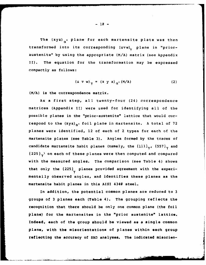
The (xyz) , plane for each martensite plate was then
transformed into its corresponding (uvw) plane in "prior-
austenite" by using the appropriate (M/A) matrix (see Appendix
II). The equation for the transformation may be expressed
compactly as follows:
(u v w) = (x y z) , (M/A) (2)
(M/A) is the correspondence matrix.
As a first step, all twenty-four (24) correspondence
matrices (Appendix II) were used for identifying all of the
possible planes in the "prior-austenite" lattice that would cor-
respond to the (xyz)Q, foil plane in martensite. A total of 72
planes were identified, 12 of each of 2 types for each of the
martensite plates (see Table 3). Angles formed by the traces of
candidate martensite habit planes (namely, the {1111y, {557}y and
{225} Y' on each of these planes were then computed and compared
with the measured angles. The comparison (see Table 4) shows
that only the (2251 planes provided agreement with the experi-
mentally observed angles, and identifies these planes as the
martensite habit planes in this AISI 4340 steel.
In addition, the potential common planes are reduced to 3
groups of 3 planes each (Table 4). The grouping reflects the
recognition that there should be only one common plane (the foil
plane) for the martensites in the "prior austenite" lattice.
Indeed, each of the group should be viewed as a single common
plane, with the misorientations of planes within each group
reflecting the accuracy of SAD analyses. The indicated misorien-
- ~ I ~ t~~A.

I- 11 -
tation , for example, between (335) and (547) is about 4.70,
and that between (1.2 1.3 3.3) for plate III and the other two
is about 120. The larger error is attributable to the thinness
of foil in this region and the attendant error in defining plane
normal from SAD analysis (25], and is nevertheless acceptable.
Within the indicatederror, the common plane is considered to be
one of the {335) planes given in Table 5.
Final selection of one of the (335) planes as the common
plane and of the associated correspondence matrices was made by
considering the directions of martensites in the thin foil
(bright field image) in relation to the SAD patterns. Using
martensite plates I and II (Fig. 4(a)), the calculated traces of
martensites for the (3 3 5)7 plane (namely, [1 0.4 7 a' and
[1 1 1] ,) provided the closest agreement with observations.
One may conclude, therefore, that the martensite habit
planes in the AISI 4340 steel used in this study are the {225)}
planes. The foil plane in which martensites appear as triads
with approximately 600 included angles has been identified as
(335) . Since this plane is close to (ll),, the consistency
between the observed configuration of martensites in the thin
foil and that of the oblong elements on the quasi-cleavage facets
provides further confirmation of the nature of quasi-cleavage in
this steel.
5.0 DISCUSSIONS
This study has shown that quasi-cleavage produced by hydro-
gen assisted cracking in AISI 4340 steel occurred on planes
parallel to 11 0) in the martensite lattice. Similar results

- 12 -
were reported recently for internal hydrogen embrittlement in
pure iron and in other steels [1-8]. It was suggested that slip
planes can act, under stress, as hydrogen accumulation sites, and
that cracking can occur as a result of the interaction between
hydrogen and the slip structure (e.g., slip bands or cells)
[6,8]. This interpretation may apply also to the case of quasi-
cleavage.
Quasi-cleavage, however, is not always an important fracture
mode. For example, only small amounts of quasi-cleavge were
observed in the AISI 4340 steels [14-16]. For specimens tested
in hydrogen at 133kPa and 270K, QC amounted to about 14 ± 7 pct
(estimated 95 pct confidence interval) of the fracture surface.
The predominant component was cracking along the prior-austenite
grain boundaries. Thus, it appears that quasi-cleavage would
occur only when no favorably oriented prior-austenite grain
boundaries are available.
Although the principal morphology of quasi-cleavage is as
described, there are a few exceptions. Some QC facets do not
show discernible geometrical markings, and some others exhibit
markings at angles that differ significantly from 600. These
minor exceptions may be caused by concomitant ductile tearing,
which obscured the geometrical markings in the first case, and by
having the QC facets oriented at large angles with respect to the
macroscopic crack plane in others. An example for the latter
case is given by QC facet 2-2' in Fig. 2.
In principle, the proposed method for determining martensite
habit planes can be used without foreknowledge of the candidate
habit planes, because the geometrical relationship between
t
- 13 -
martensite traces on a flat thin foil is unique for a specific
habit plane system. In this case, very precise determinations of
beam directions and precise trace analyses would be required.
6.0 SUMMARY
In this study, the crystallographic features of quasi-
cleavage produced by sustained-load crack growth in AISI 4340
steel, exposed to hydrogen and to hydrogen sulfide, have been
examined. A method has been proposed for determining the marten-
site habit planes without the need for concomitant presence of
retained austenite or annealing twins in the martensitic micro-
structure. The results showed that quasi-cleavage occurred along
(110) , planes through martensites. The habit planes of marten-
sites have been separately identified as {225).. Markings on the
QC facets have been shown to be consistent with cracking along
(1101., through martensites with (225)y habit planes.
ACKNOWLEDGEMENT
This work was supported in part by the Office of Naval
Research under Contract N00014-75-C-0543, NR 036-097. Helpful
discussions with Dr. A. Marder of the Homer Research Laboratory,
Bethlehem Steel Corporation is gratefully acknowledged.
21 II

- 14 -
APPENDIX I
Angles Formed by Traces of Martensite Laths on (110) a
The intersections of martensite laths or plates with the
(111) plane produce traces on this plane which would have theY
same angular relationships as those on the corresponding (110) ,
plane in the martensite lattice. The angular relationships
between these traces can be readily determined by using the zone
law and the corresponding direction cosines (i.e., dot-product of
two vectors).
i j k
a - a, i + a 2 j + a3 k- h k 1 (I-1)
u v w
b - b I i + b 2 + b 3 k - h k 1 (1-2)
u' V w
cos = /( I 1) (-3)*
The vectors a and b are the intersections of (u v w) and
(u' v' w') planes with (h k 1) plane respectively. The angle 0
is formed by a and b.
The intersections of (111) martensite laths with the (111)'V Y
plane have been determined and are listed in Table I-1.
*For iron-carbon alloys containing less than 0.6 pct carbon, itis reasonable to ignore the tetragonality of the martensitelattice [24,25).
. ........ ~~~~~~~~~~~~. III .. ." ." .... ." " " . ..- ,"L . hl..

- 15 -
Table I-1
Traces of Martensite with {ill) Habit Planes on (ill)Y Y
Habit Plane Trace on (111)
(111) [110]Y Y
(111) [101]
(111) [011 ]
Obviously, these traces form 600 angles with respect to each
other.
For {225)7 and {557}7 habit planes, the martensite laths do
intersect with (ill) and produce traces that also form 600Y
angles with respect to each other (see Table 1-2).
Table 1-2
Traces of Martensite with {225} and {557} Habit Planes on (111)Y Y
Habit Planes Trace on (111)
(22 5), (2 25 )y [110]y
( 2 52 ) ,, ( 2 2 ) , [101] ,
(52 2 ), (522) Y [011]7
155s )Y, (557).Y. [1101 Y
Y
(755)S, (7ss)y (011]'lY

- 16-
The (225)., (252)y and (522) planes are oriented at 960 with
respect to (111)Y and are the more 1ikely habit planes associated
with shearing deformation in (111).. The (2 2 5)y , (2 5 2 )y and
(522). form angles of approximately 250 with (111)y, and are not
considered to be the likely habit planes for shearing on (111)}.
Similarly (55 7 )y, (5 7 5) and (755) are oriented at 800 with
respect to (111) and are considered to be likely habit planes;
while the others are not.
- 17 -
APPENDIX II
Lattice Correspondence between Austenite and Martensite
To transform the (uvw)., plane in martensite into its cor-
responding (hkl)T plane in the "prior-austenite", one needs to
establish the correspondence matrix (M/A) for the transformation.
Following the method of Jaswan and Wheeler [261, based on ana-
lytical geometry, the lattice correspondence matrix can be estab-
lished from the relative orientation between austenite and
martensite.
For the case of iron-carbon alloys, the relative orientation
between austenite and martensite is described by the set of
Kurdjumov-Sachs relationships [21,23]. Since there are twenty-
four (24) variants of the Kurdjumov-Sachs relationships, a total
of 24 correspondence matrices needs to be established and
examined. These matrices are given in Table II-1.
The specific lattice correspondence matrices that operate in
the transformation may be selected in accordance with (i) the
specific variants of Kurdjumov-Sachs relationships that are known
or are given, and (ii) the conditions of constraint for the
differently oriented martensite laths or plates within a single
"prior-austenite" grain. The conditions of constraint are
imposed to ensure that the foil normals for the martensite laths
or plates are compatible with one another. In other words,
because the martensites are in the same foil and are contained
within one "prior-austenite" grain, the foil normals deduced from
them must correspond or transform to the same foil normal in the
corresponding "prior-austenite" lattice.

-18 -
Table II-I
Lattice Correspondence Matrices (M/A)
No. Variant Matrix No. Variant Matrix
1. (111)11 1 1 1 0 2. (1110111 1i 1(1 1 0
3. (111)(110 1 0 1 4.6 (111)(10 0 1z 0
1 0 1
7. (11-1) (110 ] 0 1 8. (111) [110] 0 1 001 01 1
9. (111) [101 0 0 1 1. (111) (101] 1 1(0 0
11. (111)110111 10 1 12. (111)[01-1 0Z 0
0e 0 1
15. (1711) [zi]o 0 4,6 (111) [i7oo] 1 00
17. (111)(011 0 1 0 18. (111)(011 1 0 1
1. (111)(011z 0 1 0 20. (111)(0111 1 _0 11 (1 10)
21. (111)[1011] 1 22. (i11) [1011 0 0
0 1 0)
23. (11)10 0 0 4. (111)[10 0 1 1
S0 bu

r- 19-
T
REFERENCES
1. I. M. Bernstein: Met. Trans.,l (1970), p. 3143.
2. F. Terasaki and F. Nakasato: in Proc. of Conf. on mechanismof delayed fracture caused by hydrogen, Tokyo (1975), p. 165.
3. F. Nakasato and I. M. Bernstein: Met. Trans.,9A (1978), p. 1317.
4. H. Takahashi, T. Takeyama and T. Hara: Nihon-Kinzoku Gakkaishi,43 (1979), p. 492.
5. A. Inone, Y. Hosoya and T. Masumoto: Tetsu-to-Hagan6, 65(1979), p. 5.
6. Shigeharu Hinotani, Fukunaga Terasak and Fukukazu Nakasato:in Proceedings JIMIS-2, Hydrogen in Metals (1980), Tokyo,p. 421.
7. T. Takeyama and H. Takahashi: in Proceedings JIMIS-2, Hydrogenin Metals (1980), Tyoko, p. 409.
8. Takao Araki and Yoneo Kikuta: in Proceedings JIMIS-2, Hydrogenin Metals (1980), Tokyo, p. 425.
9. A. W. Thompson: in Environment Degradation of EngineeringMaterials, M. R. Louthan and R. P. McNitt, eds., VPI Press,Blacksburg, VA (1977), pp. 3-17.
10. A. W. Thompson and I. M. Bernstein: in Fracture, 2, D. Taplin,ed., Univ. of Waterloo Press, Waterloo, Ont. (1977), pp. 249-54.
11. A. W. Thompson and I. M. Bernstein: in Hydrogen in Metals, (Paris)3., Paper 3A-6, Pergamon Press, New York (1977).
12. A. W. Thompson and I. M. Bernstein: in Hydrogen Effects in
Metals, The Met. Society of AIME press, New York (1981), p. 291.
13. J. E. Costa and A. W. Thompson: Met. Trans., 12A (1980), p. 761.
14. G. W. Simmuons, P. S. Pao and R. P. Wei: Met. Trans., 9A (1978),pp. 1147-1158.
15. M. Lu, P. S. Pao, N. H. Chan, K. Klier and R. P. Wei: inProceedings JIMIS-2, Hydrogen in Metals (1980) Tyoko, p. 449.
16. M. Lu, P. S. Pao, T. W. Weir, G. W. Simmons and R. P. Wei:Met. Trans., 12A (1981), p. 805.
17. T. Taoka, F. Furubayashi, and S. Takench: Japanese Journalof Applied Physics, 4, (1965) p. 120.
18. Metals Handbook, 8, 8th Edition, ASM (1973), p. 69.
19. J. S. Bowles: Acta Crystallographic, 4 (1951), p. 162. i• i-. , -

-20-
20. A. R. Marder and G. R. Krauss, Trans. ASH, 62 (1969), p. 947.
21. C. M. Wayman: in Introduction to the Crystallography ofMartensite Transformation, the MacMilian Company, New York,p. 153.
22. A. H. Greninger and A. R. Troiano: Trans. AIME, 140 (1940), p.307.
23. G. Kurdjumov and G. Sachs: Z. Phys., 64 (1930), p. 325.
24. P. L. Ryder and W. Pitsch: Phil. Mag., 18 (1968), p. 807.
25. C. Laird, E. Eichen and W. R. Bitler: J. Appi. Phys., 37(1966), p. 2225.
26. M. A. Jaswan and J. A. Wheeler: Acta Crystallographica, 1(1948), p. 10.

-21 -
E-1- + 0
00 4J4 %o
tn 0
E-10
>Iz LL
ZE4 C O
en -.r-f- -0C C-
01 0
E-4 * o a'
E-4 -V) S * + * L
E-4 *- -Z F- w .)4-JE U 4J
ail 0 4A A fCo. 0
EL ffl -_ w m C)C
0H 0a C g
40 CY0
004 E 0 ~ L
u 4J
030 CA 41)
F-C~J40100 M
>- 4J F
H z C VE40

- 22 -
TABLE 2
Angles Between Microstructural Elements
Photo Angle A Angle B Angle CNo.
1 60 64 56
2 61 63 56
3 61 63 564 61 63 56
5 60 62 58
6 61 - -
Average 60.6 63.0 56.4
From scanning electron fractographs

- 23 -
TABLE 3
Twenty-four possible foil planes in the "prior-austenite"lattice for each (x y z)a, foil plane in martensite
Foil Plane in (431) (641) , (1 1.2 2.3),Martensite Lattice a a a
Foil plane in "prior- f3351 (547) [1.3 1.2 3.3) 7
austenite" lattice* (117}) (2 1 101 {2.2 0.2 2.3}
12 possible planes for each class of planes indicated.The specific planes may be determined through the useof (M/A) matrices and the Kurdjumov-Sachs relations(see Appendix II).
I

-24-
TABLE 4
Calculated Angles Between Martensite Plates on (u v w
Potential Commnon Candidate Habit PlanesPlanes From Martensite Angle
P late 11111 {557} {225}
(3 35) ~ A 65 63 61.5
(353 ) y B 65 63 59.5
(3)yC 50 54 59
(547) A 66 63 61.1
11 (574 ) y B 63 62 60.8
(74 5) y C 51 55 58.1
(1.2 1.3 3.3) A 71.3 62 60.8
111 (1.3 3.3 1.2 ) y B 71.3 59.8 59.8
(3.3 1.2 1.3 ) y C 37.4 58.2 59.4
Measured Angles: A =630, B =590 and C =580
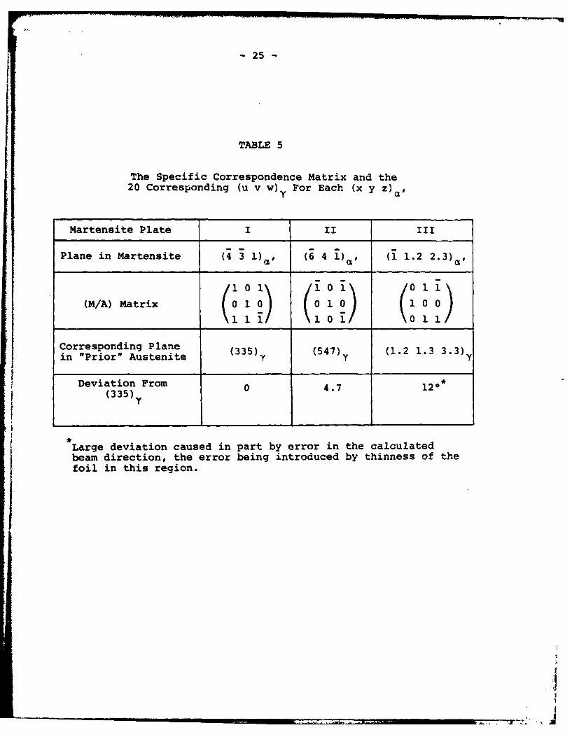
- 25 -
TABLE 5
The Specific Correspondence Matrix and the20 Corresponding (u v w) For Each (x y z)a ll
Martensite Plate I II III
Plane in Martensite 14 3 1) , (6 4 1)a ' (1 1.2 2.3) a ,
(M/A) Matrix
Corresponding Plane (335) (547) (1.2 1.3 3.3)in "Prior" Austenite y y y
Deviation From 0 4.7 120*(335) 0
'I
Large deviation caused in part by error in the calculatedbeam direction, the error being introduced by thinness of thefoil in this region.

- 26 -
FIGURE CAPTIONS
Fig. 1: SEM micrographs of (a) QC facet and (b) martensitestructure.
Fig. 2: SEM micrographs of QC facets on mating fracturesurfaces.
Fig. 3: (a) SEM micrograph of etch-pits on a QC facet, and(b) sketches of the pit shape on {100} and {110}plane in a b.c.c. cyrstal.
Fig. 4: Transmission electron micrographs of intersectingmartensite plates.
Fig. 5: Selected area diffraction pattern for martensiteplate I (in Fig. 4) and its indices.
Fig. 6: Selected area diffraction pattern for martensiteplate II (in Fig. 4) and its indices.
Fig. 7: Selected area diffraction pattern for martensiteplate III (in Fig. 4) and its indices.

-27-
4J
4-4
0
'-4
0'

-28-
C)
"ID
0
'to)
o--

-29-
4 J 4 J
004
0~ .- U
t,-444)
4
V-, -
-0

-30-
u
C)4)
0
.0
W 4J
-,-
-4
Wa;
-31-
Fig. 5: Selected area diffraction pattern formartensite plate I (in Fig. 4) and itsindices.

-32 -
of~~ ~ ib ot n 34 4
Fig. 6:Sele~Tedaeifrcinpatr6o
Fig.6:melrteditepat difra(in Fig.er 4)oan
its indices.

-33 -
(I 624as
Fig. ~ f~ 7: Seetdaeadfrcin atr omartesiteplat III(in ig. ) an
it idies
uI

BASIC DrSTRIBUTION LIST
Technical and Sumary Reports April 1978
Organization copies Orcanizatlon Covles
Defense Documentaon Center Naval Air Propulsion Test CenterCameron Station Trenton, NJ 08628Alexandria, VA 22314 12 ATTN: Library
Office of Naval Research Naval Construction BatallionDepartent of the Navy Civil Engineering Laboratory800 N. Quincy Street Port Hueneme, CA 93043Arlington, VA 22217 ATTN: Materials Division
ATTN: Code 471 1 Naval Electronics LaboratoryCode 102 1 San Diego, CA 92152Code 470 1 AM: Electron Materials
Sciences DivisionOffice of Naval Research Naval Missile CenterBranch Office Materials ConsultantBuilding 114, Section D Code 3312-1666 SiMe Street Point Mugu, CA 92041Boston, MA 02210 1
Comnding Officer.Comanding Officer Naval Surface Weapons CenterOffice of Naval Research White Oak LaboratoryBranch Office Silver Spring, MO 20910536 South Clark Street ATTN: LibraryChicago, IL 60605 1
David W. Taylor Naval ShipOffice of Naval Research Research and Development CenterSan Francisco Area Office Materials DepartmentOne Hallidie Plaza Suite 601 Annapolis, Mi 21402San Francisco, CA 94102 1
Naval Undersea CenterNaval Research Laboratory San Diego, CA 92132Washington, C 20375 ATTN: Library
ATTN: Codes 6000 1 Naval Underwater System Center6100 1 Newport, Rr 028446300 1 ATTN: Library6400 12627 1 Naval Weapons Center
China Lake, CA 93555Naval Air Developmnt Center ATTN: LibraryCode 361WarInster, PA 18964 Naval Postgraduate SchoolATTN: Mr. F. S. Willtiam I Monterey, CA 93940
ATTN: Mechanical EngineeringDeparnent
A

BASIC DISTRIBUTION LIST (cont'd)
Organi zati on Copes Organization Copies
Naval Air System Cm=mnd NASA HeadquartersWashington, OC 20360 Washington, DC 20546ATTN: Codes 52031 ATTN: Code-.Rm1
52032NASA
Naval Sea System Command Lewis Research CenterWashington, DC 20362 21000 Brookpark RoadATTN: Code 035 1 Cleveland, OH 44135
ATTN: LibraryNaval Facilities Engineering
Commnd National Bureau of StandardsAlexandria, VA 22331 Washington, DC 20234ATTN: Code 03 1 ATM: Metallurgy Division I
Inorganic Materials Div. IScientific AdvisorCommandant of the Marine Corps Director Applied Physics LaboratoryWashington, OC 20380 University of WashingtonATTN: Code AX 1 1013 Northeast Forthieth StreetSeattle, WA 98105Naval Ship Engineering Center
Department of the Navy Defense Metals and CeramicsWashingtoo, DC 20360 Information CenterATTN: Code 6101 1 Battelle Memorial Institute
505 King AvenueAmy Research Office Columbus, OH 43201P.O. Box 12211Triangle Park, NC 27709 Metals and Ceramics DivisionATM7: Metallurgy & Ceramics Program 1 Oak Ridge National Laboratory
P.O. BOx XArmW Materials and Mechanics Oak Ridge, TN 37380
Research CenterWatertown, MA 02172 Los Alamos Scientific LaboratoryATN: Research Programs Office I P.O. Box 1663
Los Alamos, NM 87544Air Force Office of Scientific ATTN: Report Librarian
ResearchBldg. 410 Argonne National LaboratoryBolling Air Force Base Metallurgy DivisionWashington, DC 20332 P.O. Box 229ATTN: Chemical Science Directorate 1 Lemont, IM 60439
Eletronics & Solid StateSciences Directorate I Brookhaven National Laboratory
Technical Information DivisionAir Force Materials Laboratory Upton, Long IslandWright-Patterson AFB New York 11973Dayton, OH 46433 1 ATTN: Research Library
Library Office of Naval ResearchBuilding 50, hi 134 Branch OfficeLmwem Radiation Laboratory 1030 East Green StreetBerkeley, CA 1 Pasadena, CA 91106 I
03616 November 1981
DISTRIBUTION LISTCorrosion Mechanisms
Professor J. P. Hirth Dr. Barry C. SyrettOhio State University Stanford Research InstituteDepartment of Metallurgical Engineering 333 Ravenswood Avenue1314 Kinnear Road Menlo Park, CA 94025Columbus, OH 43212
Prof. S. WeissmannDr. J. Kruger Rutgers, The State UniversityNational Bureau of Standards of New JerseyWashington, DC 20234 College of Engineering
New Brunswick, NY 08903Dr. H. K. BirnbaumUniversity of Illinois Prof. H. HermanDepartment of Metallurgy and Mining Engineering State University of New YorkUrbana, IL 61801 Material Science Department
Stony Brook, NY 11794Dr. D. J. DuquetteRensselaer Polytechnic Institute Prof. R. M. LatanisionDepartmen of Metallurgical Engineering Massachusetts Institute ofTroy, NY 12181 Technology
77 Massachusetts Avenue, Room E19-702Dr. R. P. Wei Cambridge, MA 02139Lehigh University Prof. E. A Starke. Jr.Institute for Fracture and Solid Mechanics. Dept. of Materials ScienceBethlehem, PA 18015 University of Virginia
Prof. H. W. Pickering Charlottesville, VA 22901Pennsylvania State University Prof. Morris E. FineDepartment of Material Science Morthestern UniversityUniversity Park, PA 16802 The Technological Institute
Prof. I. M. Bernstein Evanston, IL 60201Carnegi-Mellon University Dr. C. S. KortovichSchenley Park Tr. c.Pittsburg, PA 15213 TRW, Inc.
2355 Euclid AvenueDr. T. R. Beck Cleveland, OH 44117Electrochemical Technology Corporation Dr. 0. Buck10035 31st Avenue, N.E. rO.BkSeattle, nA 96125 Rockwell International Science Center1049 Camino Dos RiosProf. R. T. Foley P.O. Box 1085The American University Thousand Oaks, CA 91360Washington, DC 20016 Dr. R. J. Arsenault
Dr. 0. L. Davidson University of MarylandSuthwest Research Institute College ParkMID 207428S0 Culebra Road Dr. F. MnsfeldP.O. Box Drawer 28510 Rockwell International (Science Ctr)San Antonio, TX 7 4 1049 Camino Dos Rios
P.O. Box 1085Thousand Oaks, CA 91360
- -I I-L ----77i .

Continue of Distribution List03616 November 19E
Dr. Paul Gordon Dr. Theordore R. BeckIllinois institute of Technology Electrochemical Technology CorfDepartment of Metal lurgical and Materials. 3935 Leary Way NWEngineering Seattle, Washington 98107Chicago, IL 60616
Dr. H. Leidheiser, Jr.Lehigh UniversityBethlehemi, PA 18015
Dr. J. V. AcArdl eUniversity of MarylandCollege Park, MD 20742
Or . E. McCaffertyNaval Research LaboratoryWashington, DC 20375
Prof. J. G. ByrneThe University of UtahDept. of Materials Science & EngineeringSalt Lake ,City, Utah 84112
Prof. A. J. ArdellUniversity of CaliforniaSchool of Engineering and Applied Science405 Hilgard Ave.Los Angeles, CA 90024
Prof. 3 . A. S. GreenMartin Marietta Corporation1450 South Rolling RoadBaltimore,, MD 21227
Prof. LK. Miler & F.S. Pettit(Uiversity of PittsburghDept. of Mtallurgical and MaterialsEngineeringPittsburgh, PA 15261
Prof. Alexander N. CruickshmnkGordon Research ConferencePastore Chemical LaboratoryUmvivrsity of Rhode Island
Ktn5ton., Rr =&I.

I DATE
'ILME