planetary steer axle knuckle designs dessins de … · table of contents table of contents asbestos...
TRANSCRIPT

Models / Modèles PSS165PSS166PSC204PSC205PSOC205
PSC353PSC594PSC822PSC824PSTC824
PSC825PSC826PSC1044PSC1045PSC1485
PSC1614PSC1615PSC1617PSC1764PSC1794
PSC1875PSC1876PSC4564PSC4565PSC5494
Planetary Steer Axle Knuckle DesignsDessins de pivots pour ponts directeursavec planétaires
Issued 09-08Edité 09-08
Maintenance Manual 9JManuel de maintenance 9J
TM
Service Notes
Copyright 2003 Maintenance Manual MM-4APage 1 AxleTech International Issued 04-03
Service Notes
This maintenance manual describes the correct service and repair procedures for all North American AxleTech planetary steer axle knuckle designs. The information contained in this manual was current at time of printing and is subject to change without notice or liability.
You must follow your company procedures when you service or repair equipment or components. You must understand all procedures and instructions before you begin to work on a unit. Some procedures require the use of special tools for safe and correct service. Failure to use special tools when required can cause serious personal injury to service personnel, as well as damage equipment and components.
The instructions contained in this Field Maintenance Manual are intended for use by skilled and experienced mechanics knowledgeable in the installation, repair and replacement of the AxleTech product described herein. Installation, maintenance and replacement of such products require a high degree of skill and experience. The consequences of improper installation, maintenance or replacement (including the use of inferior or substandard components) are grave and can result in product failure and resulting loss of control of the vehicle, possible injury to or death of persons and/or possible future or additional axle damage. AxleTech does not authorize anyone other than highly skilled and experienced individuals to attempt to utilize the instructions contained in this Manual for the installation, maintenance or replacement of the product described herein, and AxleTech shall have no liability of any kind for damages arising out of (or in connection with) any other use of the information contained in this Manual.
AxleTech International uses the following notations to warn the user of possible safety problems and to provide information that will prevent damage to equipment and components.
How to Order
Order items from AxleTech International.
Phone orders are also accepted by calling AxleTech International’s Customer Service Center at 877-547-3907 or send a fax to 866-547-3987.
WARNING
A WARNING indicates a procedure that you must follow exactly to avoid serious personal injury.
CAUTION
A CAUTION indicates a procedure that you must follow exactly to avoid damaging equipment or components. Serious personal injury can also occur.
This symbol indicates that fasteners must be tightened to a specific torque.
NOTE
A NOTE indicates an operation, procedure or instruction that is important for proper service. A NOTE can also supply information that will help to make service quicker and easier.
Table of Contents
Table of Contents
Asbestos and Non-Asbestos Fibers Warnings
. . . . . . . . . . . . . . . . . . . . . . . . . . . . . . . . . . . . . . . . . . . . . . . . 1
Exploded View
. . . . . . . . . . . . . . . . . . . . . . . . . . . . . . . . . . . . . . . . . . . . . . . . . . . . . . . . . . . . . . . . . . . . . . . . . . . . . . . . . . . 2
Section 1: Introduction
Description . . . . . . . . . . . . . . . . . . . . . . . . . . . . . . . . . . . . . . . . . . . . . . . . . . . . . . . . . . . . . . . . . . . . . . . . . . . . . . . . . . . . 4Axle Designs Covered in This Manual . . . . . . . . . . . . . . . . . . . . . . . . . . . . . . . . . . . . . . . . . . . . . . . . . . . . . . . . . . . . . . . 6Axle Designs Not Covered in This Manual Identification
Section 2: Removal and Disassembly
Removal . . . . . . . . . . . . . . . . . . . . . . . . . . . . . . . . . . . . . . . . . . . . . . . . . . . . . . . . . . . . . . . . . . . . . . . . . . . . . . . . . . . . . . . 8Axle Shaft Assembly Steer Knuckle King Pin Bushings . . . . . . . . . . . . . . . . . . . . . . . . . . . . . . . . . . . . . . . . . . . . . . . . . . . . . . . . . . . . . . . . . . . . . . . . . . . . . . 11Axle Shaft Oil Seal and Bushing . . . . . . . . . . . . . . . . . . . . . . . . . . . . . . . . . . . . . . . . . . . . . . . . . . . . . . . . . . . . . . . . . . 12Disassembly Steering Universal Joint
Section 3: Prepare Parts for Assembly
Clean Ground and Polished Parts . . . . . . . . . . . . . . . . . . . . . . . . . . . . . . . . . . . . . . . . . . . . . . . . . . . . . . . . . . . . . . . . . . 15Clean Rough Parts Clean Axle Assemblies Dry Parts After Cleaning Prevent Corrosion on Cleaned Parts Inspect Parts Repair or Replace Parts Do Not Bend or Straighten a Damaged Drive Axle Housing . . . . . . . . . . . . . . . . . . . . . . . . . . . . . . . . . . . . . . . . . . . . . 16Removing Fasteners Secured with Adhesive Install Fasteners New Fasteners with Pre-Applied Adhesive Original or Used Fasteners Using AxleTech Liquid Adhesive 2297-T-4180 or Loctite
®
277 Adhesive, or Equivalent Applying Silicone Gasket Material . . . . . . . . . . . . . . . . . . . . . . . . . . . . . . . . . . . . . . . . . . . . . . . . . . . . . . . . . . . . . . . . . 17Flush Lubricant From the Axle Housing
Section 4: Assembly and Installation
Assembly of Steering Universal Joint . . . . . . . . . . . . . . . . . . . . . . . . . . . . . . . . . . . . . . . . . . . . . . . . . . . . . . . . . . . . . . . 18Installation of Axle Shaft Bushing and Seal . . . . . . . . . . . . . . . . . . . . . . . . . . . . . . . . . . . . . . . . . . . . . . . . . . . . . . . . . . 19Installation of King Pin Bushings . . . . . . . . . . . . . . . . . . . . . . . . . . . . . . . . . . . . . . . . . . . . . . . . . . . . . . . . . . . . . . . . . . 20Assembly of Steer Knuckle . . . . . . . . . . . . . . . . . . . . . . . . . . . . . . . . . . . . . . . . . . . . . . . . . . . . . . . . . . . . . . . . . . . . . . . 21Sealed King Pin Bushing . . . . . . . . . . . . . . . . . . . . . . . . . . . . . . . . . . . . . . . . . . . . . . . . . . . . . . . . . . . . . . . . . . . . . . . . 23Steer Knuckle Adjustment Final King Pin Cap Installation . . . . . . . . . . . . . . . . . . . . . . . . . . . . . . . . . . . . . . . . . . . . . . . . . . . . . . . . . . . . . . . . . . . . 24Axle Components Axle Shaft and Universal Joint Spindle, Brake and Planetary Wheel End . . . . . . . . . . . . . . . . . . . . . . . . . . . . . . . . . . . . . . . . . . . . . . . . . . . . . . . . . . . . 25
Section 5: Torque Specifications
. . . . . . . . . . . . . . . . . . . . . . . . . . . . . . . . . . . . . . . . . . . . . . . . . . . . . . . . . . . . . . . . 26
Section 6: Lubrication Specifications
. . . . . . . . . . . . . . . . . . . . . . . . . . . . . . . . . . . . . . . . . . . . . . . . . . . . . . . . . . . 28

Notes

Maintenance Manual 9J Copyright 2008Issued 09-08 AxleTech International Page 1
Asbestos and Non-Asbestos Fibers
Maintenance Manual 9J Copyright 2003Issued 08-03 AxleTech International Page 1
Asbestos and Non-Asbestos Fibers
ASBESTOS FIBERS WARNING
The following procedures for servicing brakes are recommended to reduce exposure toasbestos fiber dust, a cancer and lung disease hazard. Material Safety Data Sheets areavailable from AxleTech.
Hazard Summary
Because some brake linings contain asbestos, workers who service brakes must understand the potential hazards of asbestos and precautions for reducing risks. Exposure to airborne asbestos dust can cause serious and possibly fatal diseases, including asbestosis (a chronic lung disease) and cancer, principally lung cancer and mesothelioma (a cancer of the lining of the chest or abdominal cavities). Some studies show that the risk of lung cancer among persons who smoke and who are exposed to asbestos is much greater than the risk for non-smokers. Symptoms of these diseases may not become apparent for 15, 20 or more years after the first exposure to asbestos.
Accordingly, workers must use caution to avoid creating and breathing dust when servicing brakes. Specific recommended work practices for reducing exposure to asbestos dust follow. Consult your employer for more details.
Recommended Work Practices
1. Separate Work Areas. Whenever feasible, service brakes in a separate area away from other operations to reduce risks to unprotected persons. OSHA has set a maximum allowable level of exposure for asbestos of 0.1 f/cc as an 8-hour time-weighted average and 1.0 f/cc averaged over a 30-minute period. Scientists disagree, however, to what extent adherence to the maximum allowable exposure levels will eliminate the risk of disease that can result from inhaling asbestos dust. OSHA requires that the following sign be posted at the entrance to areas where exposures exceed either of the maximum allowable levels:
DANGER: ASBESTOSCANCER AND LUNG DISEASE HAZARD
AUTHORIZED PERSONNEL ONLYRESPIRATORS AND PROTECTIVE CLOTHING
ARE REQUIRED IN THIS AREA.
2. Respiratory Protection.
Wear a respirator equipped with a high-efficiency (HEPA) filter approved by NIOSH or MSHA for use with asbestos at all times when servicing brakes, beginning with the removal of the wheels.
3. Procedures for Servicing Brakes.
a. Enclose the brake assembly within a negative pressure enclosure. The enclosure should be equipped with a HEPA vacuum and worker arm sleeves. With the enclosure in place, use the HEPA vacuum to loosen and vacuum residue from the brake parts.
b. As an alternative procedure, use a catch basin with water and a biodegradable, non-phosphate, water-based detergent to wash the brake drum or rotor and other brake parts. The solution should be applied with low pressure to prevent dust from becoming airborne. Allow the solution to flow between the brake drum and the brake support or the brake rotor and caliper. The wheel hub and brake assembly components should be thoroughly wetted to suppress dust before the brake shoes or brake pads are removed. Wipe the brake parts clean with a cloth.
c. If an enclosed vacuum system or brake washing equipment is not available, employers may adopt their own written procedures for servicing brakes, provided that the exposure levels associated with the employer’s procedures do not exceed the levels associated with the enclosed vacuum system or brake washing equipment. Consult OSHA regulations for more details.
d. Wear a respirator equipped with a HEPA filter approved by NIOSH or MSHA for use with asbestos when grinding or machining brake linings. In addition, do such work in an area with a local exhaust ventilation system equipped with a HEPA filter.
e.
NEVER
use compressed air by itself, dry brushing, or a vacuum not equipped with a HEPA filter when cleaning brake parts or assemblies.
NEVER
use carcinogenic solvents, flammable solvents, or solvents that can damage brake components as wetting agents.
4. Cleaning Work Areas. Clean work areas with a vacuum equipped with a HEPA filter or by wet wiping.
NEVER
use compressed air or dry sweeping to clean work areas. When you empty vacuum cleaners and handle used rags, wear a respirator equipped with a HEPA filter approved by NIOSH or MSHA for use with asbestos. When you replace a HEPA filter, wet the filter with a fine mist of water and dispose of the used filter with care.
5. Worker Clean-Up
.
After servicing brakes, wash your hands before you eat, drink or smoke. Shower after work. Do not wear work clothes home. Use a vacuum equipped with a HEPA filter to vacuum work clothes after they are worn. Launder them separately. Do not shake or use compressed air to remove dust from work clothes.
6. Waste Disposal. Dispose of discarded linings, used rags, cloths and HEPA filters with care, such as in sealed plastic bags. Consult applicable EPA, state and local regulations on waste disposal.
Regulatory Guidance
References to OSHA, NIOSH, MSHA, and EPA, which are regulatory agencies in the United States, are made to provide further guidance to employers and workers employed within the United States. Employers and workers employed outside of the United States should consult the regulations that apply to them for further guidance.
NON-ASBESTOS FIBERS WARNING
The following procedures for servicing brakes are recommended to reduce exposure tonon-asbestos fiber dust, a cancer and lung disease hazard. Material Safety DataSheets are available from AxleTech.
Hazard Summary
Most recently manufactured brake linings do not contain asbestos fibers. These brake linings may contain one or more of a variety of ingredients, including glass fibers, mineral wool, aramid fibers, ceramic fibers and silica that can present health risks if inhaled. Scientists disagree on the extent of the risks from exposure to these substances. Nonetheless, exposure to silica dust can cause silicosis, a non-cancerous lung disease. Silicosis gradually reduces lung capacity and efficiency and can result in serious breathing difficulty. Some scientists believe other types of non-asbestos fibers, when inhaled, can cause similar diseases of the lung. In addition, silica dust and ceramic fiber dust are known to the State of California to cause lung cancer. U.S. and international agencies have also determined that dust from mineral wool, ceramic fibers and silica are potential causes of cancer.
Accordingly, workers must use caution to avoid creating and breathing dust when servicing brakes. Specific recommended work practices for reducing exposure to non-asbestos dust follow. Consult your employer for more details.
Recommended Work Practices
1. Separate Work Areas. Whenever feasible, service brakes in a separate area away from other operations to reduce risks to unprotected persons.
2. Respiratory Protection.
OSHA has set a maximum allowable level of exposure for silica of 0.1 mg/m
3
as an 8-hour time-weighted average. Some manufacturers of non-asbestos brake linings recommend that exposures to other ingredients found in non-asbestos brake linings be kept below 1.0 f/cc as an 8-hour time-weighted average. Scientists disagree, however, to what extent adherence to these maximum allowable exposure levels will eliminate the risk of disease that can result from inhaling non-asbestos dust.
Therefore, wear respiratory protection at all times during brake servicing, beginning with the removal of the wheels. Wear a respirator equipped with a high-efficiency (HEPA) filter approved by NIOSH or MSHA, if the exposure levels may exceed OSHA or manufacturers’ recommended maximum levels. Even when exposures are expected to be within the maximum allowable levels, wearing such a respirator at all times during brake servicing will help minimize exposure.
3. Procedures for Servicing Brakes.
a. Enclose the brake assembly within a negative pressure enclosure. The enclosure should be equipped with a HEPA vacuum and worker arm sleeves. With the enclosure in place, use the HEPA vacuum to loosen and vacuum residue from the brake parts.
b. As an alternative procedure, use a catch basin with water and a biodegradable, non-phosphate, water-based detergent to wash the brake drum or rotor and other brake parts. The solution should be applied with low pressure to prevent dust from becoming airborne. Allow the solution to flow between the brake drum and the brake support or the brake rotor and caliper. The wheel hub and brake assembly components should be thoroughly wetted to suppress dust before the brake shoes or brake pads are removed. Wipe the brake parts clean with a cloth.
c. If an enclosed vacuum system or brake washing equipment is not available, carefully clean the brake parts in the open air. Wet the parts with a solution applied with a pump-spray bottle that creates a fine mist. Use a solution containing water, and, if available, a biodegradable, non-phosphate, water-based detergent. The wheel hub and brake assembly components should be thoroughly wetted to suppress dust before the brake shoes or brake pads are removed. Wipe the brake parts clean with a cloth.
d. Wear a respirator equipped with a HEPA filter approved by NIOSH or MSHA when grinding or machining brake linings. In addition, do such work in an area with a local exhaust ventilation system equipped with a HEPA filter.
e.
NEVER
use compressed air by itself, dry brushing, or a vacuum not equipped with a HEPA filter when cleaning brake parts or assemblies.
NEVER
use carcinogenic solvents, flammable solvents, or solvents that can damage brake components as wetting agents.
4. Cleaning Work Areas. Clean work areas with a vacuum equipped with a HEPA filter or by wet wiping.
NEVER
use compressed air or dry sweeping to clean work areas. When you empty vacuum cleaners and handle used rags, wear a respirator equipped with a HEPA filter approved by NIOSH or MSHA, to minimize exposure. When you replace a HEPA filter, wet the filter with a fine mist of water and dispose of the used filter with care.
5. Worker Clean-Up.
After servicing brakes, wash your hands before you eat, drink or smoke. Shower after work. Do not wear work clothes home. Use a vacuum equipped with a HEPA filter to vacuum work clothes after they are worn. Launder them separately. Do not shake or use compressed air to remove dust from work clothes.
6. Waste Disposal
.
Dispose of discarded linings, used rags, cloths and HEPA filters with care, such as in sealed plastic bags. Consult applicable EPA, state and local regulations on waste disposal.
Regulatory Guidance
References to OSHA, NIOSH, MSHA, and EPA, which are regulatory agencies in the United States, are made to provide further guidance to employers and workers employed within the United States. Employers and workers employed outside of the United States should consult the regulations that apply to them for further guidance.
Copyright 2008 Maintenance Manual 9JPage 2 AxleTech International Issued 09-08
Exploded View
Copyright 2003 Maintenance Manual 9JPage 2 AxleTech International Issued 08-03
Exploded View
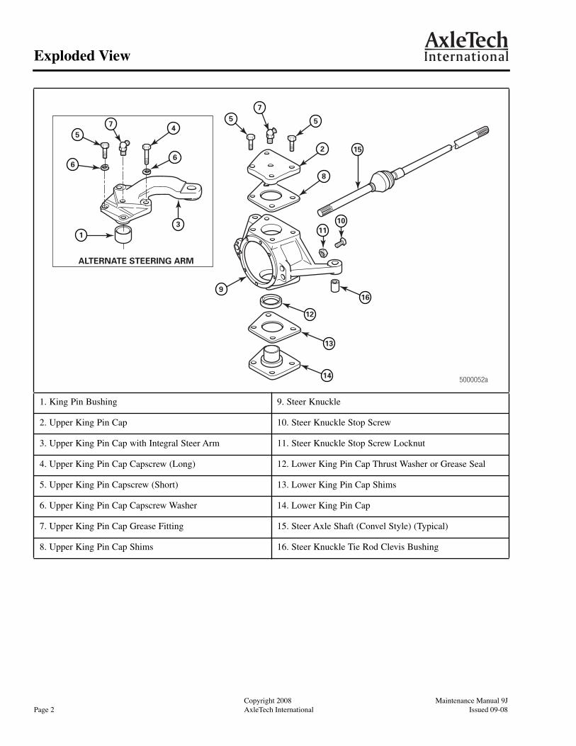
1. King Pin Bushing 9. Steer Knuckle
2. Upper King Pin Cap 10. Steer Knuckle Stop Screw
3. Upper King Pin Cap with Integral Steer Arm 11. Steer Knuckle Stop Screw Locknut
4. Upper King Pin Cap Capscrew (Long) 12. Lower King Pin Cap Thrust Washer or Grease Seal
5. Upper King Pin Capscrew (Short) 13. Lower King Pin Cap Shims
6. Upper King Pin Cap Capscrew Washer 14. Lower King Pin Cap
7. Upper King Pin Cap Grease Fitting 15. Steer Axle Shaft (Convel Style) (Typical)
8. Upper King Pin Cap Shims 16. Steer Knuckle Tie Rod Clevis Bushing
5000052a
ALTERNATE STEERING ARM
75 5
2
8
16
12
13
14
9
3
6
475
6
1
15
1110
Maintenance Manual 9J Copyright 2008Issued 09-08 AxleTech International Page 3
Exploded View
Maintenance Manual 9J Copyright 2003Issued 08-03 AxleTech International Page 3
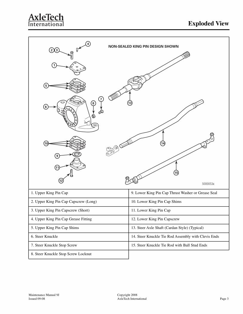
1. Upper King Pin Cap 9. Lower King Pin Cap Thrust Washer or Grease Seal
2. Upper King Pin Cap Capscrew (Long) 10. Lower King Pin Cap Shims
3. Upper King Pin Capscrew (Short) 11. Lower King Pin Cap
4. Upper King Pin Cap Grease Fitting 12. Lower King Pin Capscrew
5. Upper King Pin Cap Shims 13. Steer Axle Shaft (Cardan Style) (Typical)
6. Steer Knuckle 14. Steer Knuckle Tie Rod Assembly with Clevis Ends
7. Steer Knuckle Stop Screw 15. Steer Knuckle Tie Rod with Ball Stud Ends
8. Steer Knuckle Stop Screw Locknut
NON-SEALED KING PIN DESIGN SHOWN32
4
1
68
713
15
12
11
9
5000053a
5
10 14
Copyright 2008 Maintenance Manual 9JPage 4 AxleTech International Issued 09-08
Section 1Introduction
Copyright 2003 Maintenance Manual 9JPage 4 AxleTech International Issued 08-03
Section 1 Introduction
Description
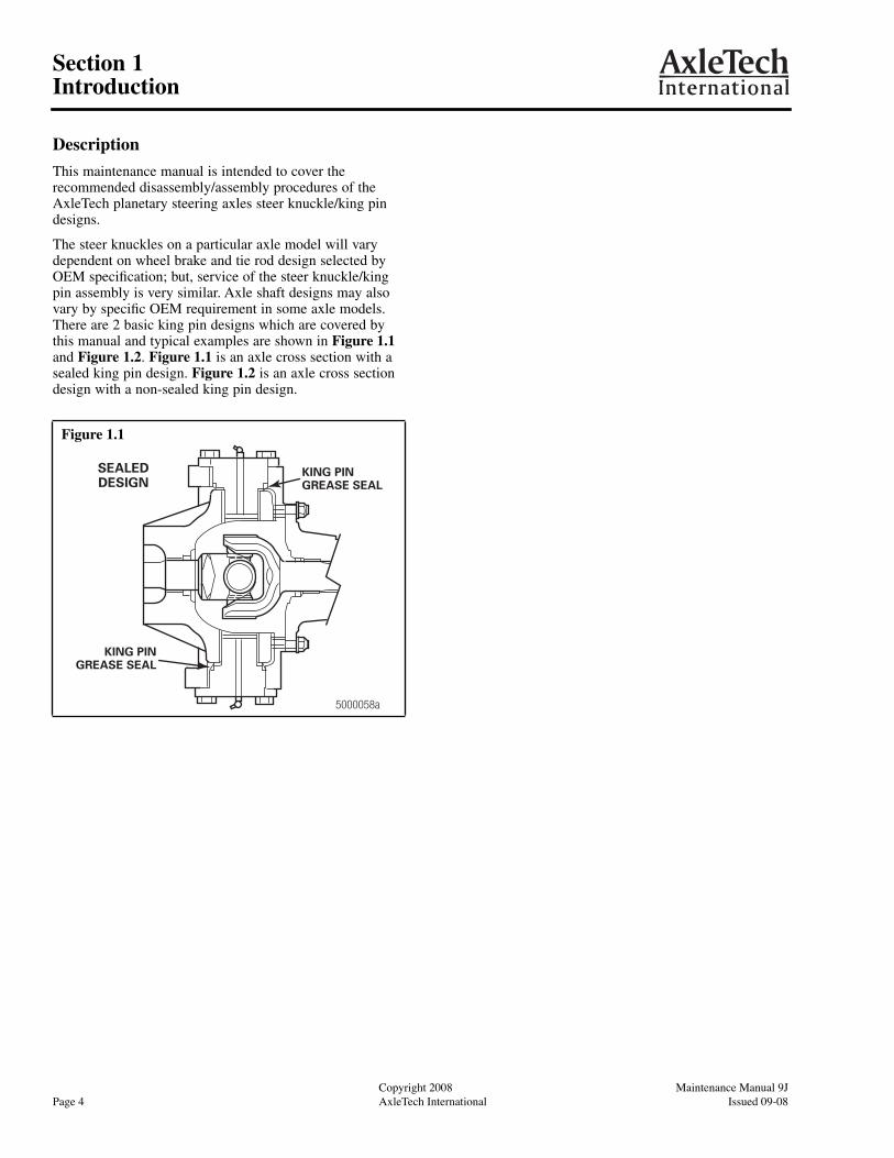
This maintenance manual is intended to cover the recommended disassembly/assembly procedures of the AxleTech planetary steering axles steer knuckle/king pin designs.
The steer knuckles on a particular axle model will vary dependent on wheel brake and tie rod design selected by OEM specification; but, service of the steer knuckle/king pin assembly is very similar. Axle shaft designs may also vary by specific OEM requirement in some axle models. There are 2 basic king pin designs which are covered by this manual and typical examples are shown in
Figure 1.1
and
Figure 1.2
.
Figure 1.1
is an axle cross section with a sealed king pin design.
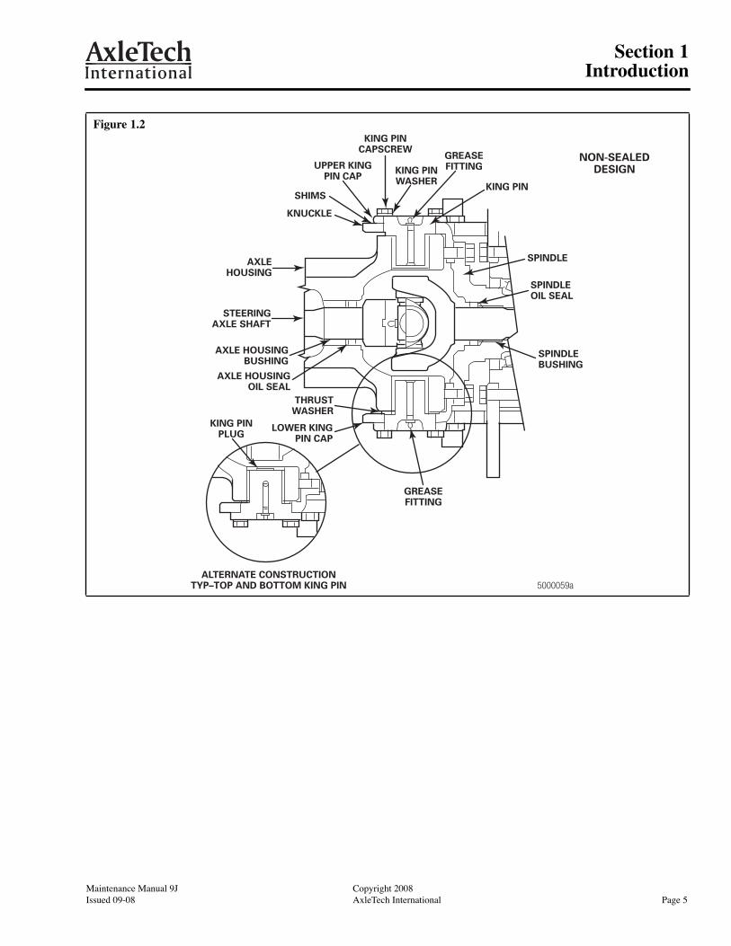
Figure 1.2
is an axle cross section design with a non-sealed king pin design.
Figure 1.1
KING PINGREASE SEAL
KING PINGREASE SEAL
5000058a
SEALEDDESIGN
Maintenance Manual 9J Copyright 2008Issued 09-08 AxleTech International Page 5
Section 1Introduction
Maintenance Manual 9J Copyright 2003Issued 08-03 AxleTech International Page 5
Figure 1.2
KING PINPLUG
SPINDLEOIL SEAL
5000059aALTERNATE CONSTRUCTION
TYP–TOP AND BOTTOM KING PIN
LOWER KINGPIN CAP
THRUSTWASHER
AXLE HOUSINGOIL SEAL
AXLE HOUSINGBUSHING
STEERINGAXLE SHAFT
AXLEHOUSING
SHIMS
KNUCKLE
UPPER KINGPIN CAP
KING PINCAPSCREW
KING PINWASHER
GREASEFITTING
KING PIN
GREASEFITTING
SPINDLE
NON-SEALEDDESIGN
SPINDLEBUSHING
Copyright 2008 Maintenance Manual 9JPage 6 AxleTech International Issued 09-08
Section 1Introduction
Copyright 2003 Maintenance Manual 9JPage 6 AxleTech International Issued 08-03
Axle Designs Covered in This Manual
The following knuckle and king pin designs are covered in this manual.
�
Non-sealed king pin
�
Sealed king pin with grease seal on king pin
�
Sealed king pin with grease seal in knuckle bore
�
Inclined king pin with grease seal on king pin
For planetary components, wheel hub, brake components and spindle service procedures, refer to the appropriate planetary axle wheel end maintenance manuals. To obtain these publications, refer to the Service Notes page on the front inside cover of this manual.
Axle Designs Not Covered in This Manual
�
Split knuckle
�
Tapered bearing king pin
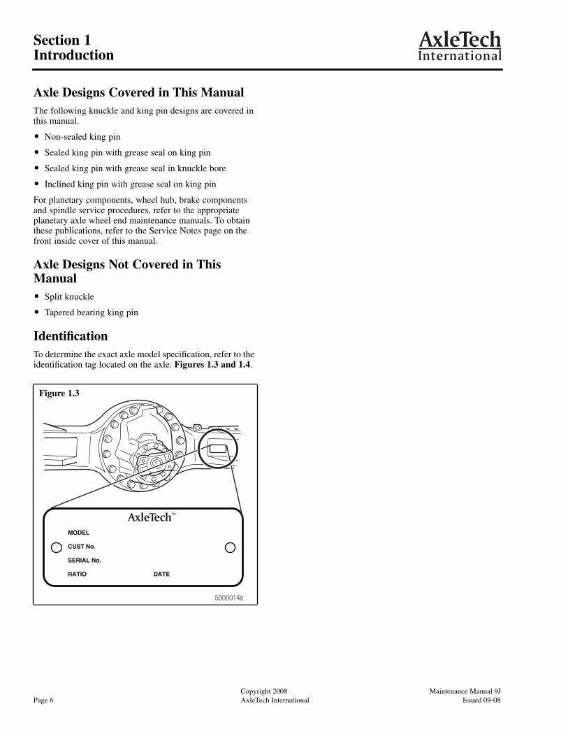
Identification
To determine the exact axle model specification, refer to the identification tag located on the axle.
Figures 1.3 and 1.4
.
Figure 1.3
5000014a
MODEL
CUST No.
SERIAL No.
RATIO DATE
Maintenance Manual 9J Copyright 2008Issued 09-08 AxleTech International Page 7
Section 1Introduction
Maintenance Manual 9J Copyright 2003Issued 08-03 AxleTech International Page 7
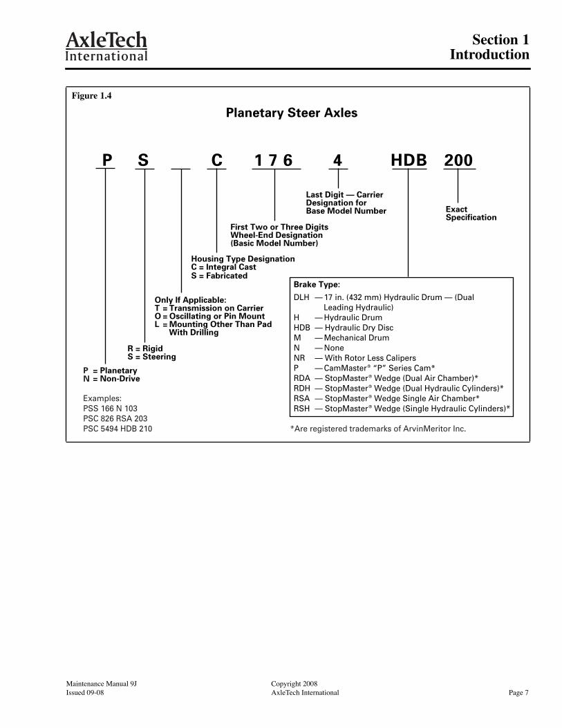
Figure 1.4
Planetary Steer Axles
P S C 1 7 6 4 HDB 200
ExactSpecification
R = RigidS = Steering
= Planetary= Non-Drive
Last Digit — CarrierDesignation forBase Model Number
First Two or Three Digits Wheel-End Designation (Basic Model Number)
Housing Type DesignationC = Integral CastS = Fabricated
Only If Applicable:T = Transmission on CarrierO = Oscillating or Pin MountL = Mounting Other Than Pad
With Drilling
Brake Type:
DLH — 17 in. (432 mm) Hydraulic Drum — (DualLeading Hydraulic)
H — Hydraulic DrumHDB — Hydraulic Dry DiscM — Mechanical DrumN — NoneNR — With Rotor Less CalipersP — CamMaster® “P” Series Cam*RDA — StopMaster® Wedge (Dual Air Chamber)*RDH — StopMaster® Wedge (Dual Hydraulic Cylinders)*RSA — StopMaster® Wedge Single Air Chamber*RSH — StopMaster® Wedge (Single Hydraulic Cylinders)*
PN
*Are registered trademarks of ArvinMeritor Inc.
Examples:PSS 166 N 103PSC 826 RSA 203PSC 5494 HDB 210
Copyright 2008 Maintenance Manual 9JPage 8 AxleTech International Issued 09-08
Section 2Removal and Disassembly
Copyright 2003 Maintenance Manual 9JPage 8 AxleTech International Issued 08-03
Section 2 Removal and Disassembly
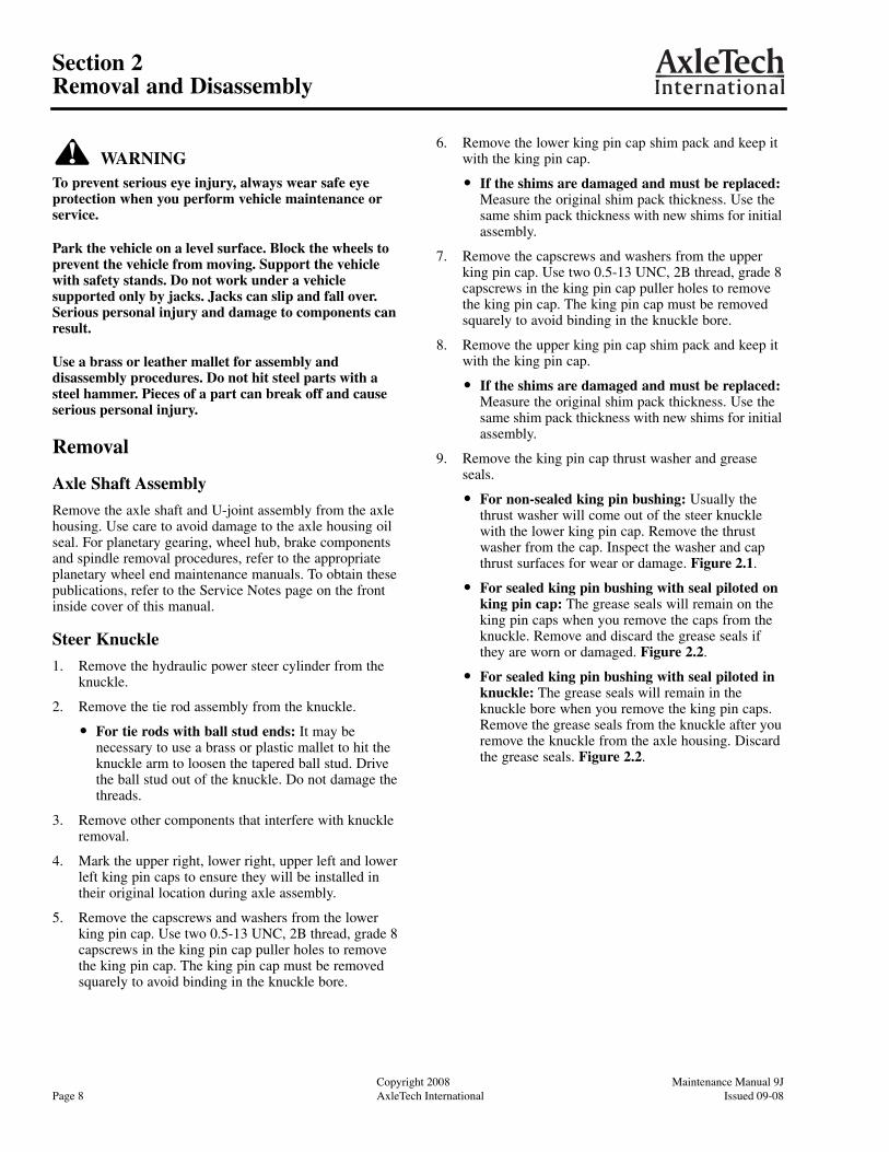
WARNING
To prevent serious eye injury, always wear safe eye protection when you perform vehicle maintenance or service.
Park the vehicle on a level surface. Block the wheels to prevent the vehicle from moving. Support the vehicle with safety stands. Do not work under a vehicle supported only by jacks. Jacks can slip and fall over. Serious personal injury and damage to components can result.
Use a brass or leather mallet for assembly and disassembly procedures. Do not hit steel parts with a steel hammer. Pieces of a part can break off and cause serious personal injury.
Removal
Axle Shaft Assembly
Remove the axle shaft and U-joint assembly from the axle housing. Use care to avoid damage to the axle housing oil seal. For planetary gearing, wheel hub, brake components and spindle removal procedures, refer to the appropriate planetary wheel end maintenance manuals. To obtain these publications, refer to the Service Notes page on the front inside cover of this manual.
Steer Knuckle
1. Remove the hydraulic power steer cylinder from the knuckle.
2. Remove the tie rod assembly from the knuckle.
�
For tie rods with ball stud ends:
It may be necessary to use a brass or plastic mallet to hit the knuckle arm to loosen the tapered ball stud. Drive the ball stud out of the knuckle. Do not damage the threads.
3. Remove other components that interfere with knuckle removal.
4. Mark the upper right, lower right, upper left and lower left king pin caps to ensure they will be installed in their original location during axle assembly.
5. Remove the capscrews and washers from the lower king pin cap. Use two 0.5-13 UNC, 2B thread, grade 8 capscrews in the king pin cap puller holes to remove the king pin cap. The king pin cap must be removed squarely to avoid binding in the knuckle bore.
6. Remove the lower king pin cap shim pack and keep it with the king pin cap.
�
If the shims are damaged and must be replaced:
Measure the original shim pack thickness. Use the same shim pack thickness with new shims for initial assembly.
7. Remove the capscrews and washers from the upper king pin cap. Use two 0.5-13 UNC, 2B thread, grade 8 capscrews in the king pin cap puller holes to remove the king pin cap. The king pin cap must be removed squarely to avoid binding in the knuckle bore.
8. Remove the upper king pin cap shim pack and keep it with the king pin cap.
�
If the shims are damaged and must be replaced:
Measure the original shim pack thickness. Use the same shim pack thickness with new shims for initial assembly.
9. Remove the king pin cap thrust washer and grease seals.
�
For non-sealed king pin bushing:
Usually the thrust washer will come out of the steer knuckle with the lower king pin cap. Remove the thrust washer from the cap. Inspect the washer and cap thrust surfaces for wear or damage.
Figure 2.1
.
�
For sealed king pin bushing with seal piloted on king pin cap:
The grease seals will remain on the king pin caps when you remove the caps from the knuckle. Remove and discard the grease seals if they are worn or damaged.
Figure 2.2
.
�
For sealed king pin bushing with seal piloted in knuckle:
The grease seals will remain in the knuckle bore when you remove the king pin caps. Remove the grease seals from the knuckle after you remove the knuckle from the axle housing. Discard the grease seals.
Figure 2.2
.

Maintenance Manual 9J Copyright 2008Issued 09-08 AxleTech International Page 9
Section 2Removal and Disassembly
Maintenance Manual 9J Copyright 2003Issued 08-03 AxleTech International Page 9
WARNING
Take care when you use lifting devices. When you use a lifting strap, inspect the strap for damage before you use it. Do not use a lifting strap to shock load or drop load a component. Serious personal injury and damage to components can result.
10. Use a lifting device to remove the planetary steer knuckle from the axle housing assembly.
Figure 2.3
.
11. Remove the knuckle from the axle housing.
Figure 2.1
Figure 2.2
NON-SEALED KING PIN BUSHING DESIGN
THRUSTWASHER
LOWER KING PIN CAP
STEERKNUCKLE
TOP
5000055a
SEALED KING PIN BUSHING DESIGN
GREASESEAL
LOWER KING PIN CAP
STEERKNUCKLE
TOP
5000056a
GREASESEAL

Copyright 2008 Maintenance Manual 9JPage 10 AxleTech International Issued 09-08
Section 2Removal and Disassembly
Copyright 2003 Maintenance Manual 9JPage 10 AxleTech International Issued 08-03
Figure 2.3
1. Planetary Spider 8. Steer Knuckle Tie Rod Nut Cotter Pin
2. Wheel Hub 9. Steer Knuckle Tie Rod Assembly with Ball Stud Ends
3. Upper King Pin Capscrews (4) 10. Lower King Pin Cap Thrust Washer or Grease Seal
4. Upper King Pin Cap 11. Lower King Pin Cap Shims
5. Upper King Pin Cap Shims 12. Lower King Pin Capscrews (4)
6. Steer Knuckle 13. Lower King Pin Cap
7. Steer Knuckle Tie Rod Assembly Nut 14. Axle Housing
5000057a
33
4
5
6
1
2
1312
11
10
8
714
9

Maintenance Manual 9J Copyright 2008Issued 09-08 AxleTech International Page 11
Section 2Removal and Disassembly
Maintenance Manual 9J Copyright 2003Issued 08-03 AxleTech International Page 11
King Pin Bushings
Inspection
Inspect the king pin bushings in the axle housing.
�
If the king pin bushings are worn or damaged:
Use one of the procedures below to remove the bushings.
�
If the king pin bushings are not worn or damaged:
Proceed to Axle Shaft Oil Seal and Bushing.
Non-Sealed King Pin Bushings
1. Grind off the tack welds that hold the expansion plug in the housing bore.
Figure 2.4
.
2. Use a drift that fits through the king pin bushing to remove the expansion plug by driving it TOWARD the center of the trunnion.
Figure 2.5
.
3. Use a sleeve that is slightly smaller than the housing bore to remove the king pin bushing by driving it TOWARD the outside of the trunnion.
Figure 2.6
.
4. Use an emery cloth to clean the housing bores and remove burrs.
Sealed King Pin Bushings
1. Use a sleeve that is slightly smaller than the housing bore to remove the bushing by driving it TOWARD the outside of the trunnion.
Figures 2.6 and 2.7
.
2. Use an emery cloth to clean the housing bores and remove burrs.
Figure 2.4
Figure 2.5
BUSHING
EXPANSIONPLUG
NON-SEALED DESIGN5000063a
4000729a
Figure 2.6
Figure 2.7
4000730a
SEALED DESIGN
FLANGEDBUSHING
5000062a

Copyright 2008 Maintenance Manual 9JPage 12 AxleTech International Issued 09-08
Section 2Removal and Disassembly
Copyright 2003 Maintenance Manual 9JPage 12 AxleTech International Issued 08-03
Axle Shaft Oil Seal and Bushing
1. Note the position of the axle shaft oil seal in the housing bore. The oil seal may be installed with the outer face flush with the machined counterbore or it may be pressed further into the housing bore.
Figures 2.8 and 2.9
. Should the oil seal be installed into machined bore, record oil seal installation depth “X” for later reinstallation of new oil seal assembly.
NOTE:
You must install a new oil seal in the housing bore at the same depth as the original factory installation.
2. Remove the axle shaft oil seal from the housing. Do not damage the housing bore. A damaged bore can allow oil leakage past the outside diameter of a new seal.
Figure 2.9
.
3. Inspect the axle shaft bushing. Remove the bushing from the axle housing if it is worn or damaged.
Figure 2.9
.
Disassembly
Steering Universal Joint
NOTE:
Do not disassemble Permalube universal joints. Disassembly will void the AxleTech warranty. This style has no grease fitting on the center parts assembly.
NOTE:
AxleTech planetary steer axles have three universal joint designs.
�
Wing bearing yokes,
Figure 2.10
.
�
Round bearing yokes or cardan joint,
Figure 2.11
.
�
Constant velocity joints,
Figure 2.12
.
Figure 2.8
Figure 2.9
SEAL FLUSHWITH COUNTERBORE
FACE
COUNTERBOREFACE
5000060a
SEAL PRESSEDDEEP INTO BORE
AXLESHAFTBUSHING
AXLESHAFT
OIL SEAL
5000061a
Figure 2.10
1 WING BEARING YOKE
Figure 2.11
1 ROUND BEARING YOKE
4000733a
4000734a

Maintenance Manual 9J Copyright 2008Issued 09-08 AxleTech International Page 13
Section 2Removal and Disassembly
Maintenance Manual 9J Copyright 2003Issued 08-03 AxleTech International Page 13
Wing Bearing Yokes
1. Remove the four cross assembly capscrews from each yoke.
2. Inspect the cross assembly.
�
If the cross assembly requires service:
Replace it with a new assembly. Do
Not disassemble the cross assembly.
Round Bearing Yokes or Cardan Joint
1. Use a suitable tool to remove the snap rings from the two ears in each yoke. Figure 2.13.
2. Place the joint assembly in an open vise with one yoke resting horizontally on top of the vise jaws. Do not tighten the vise.
3. Use a suitable soft hammer to tap the upper ear of the vertical yoke several times. Drive the vertical yoke down and push out the upper needle bearing and cap. Figure 2.14. The bearing cap has a highly polished surface. Do not mar or scratch the surface during removal.
� If the metal retainers have loosened from the bearing caps: Remove the retainers from the arms of the cross through the hole in the yokes.
4. Turn the vertical yoke over. Repeat Step 3 to remove the needle bearing and retainer on the opposite side. Figure 2.15.
5. Remove the yoke by gently moving the yoke off the arms of the cross.
Figure 2.12
Figure 2.13
5000071a
4000735a
Figure 2.14
Figure 2.15
5000065a
5000066a
Copyright 2008 Maintenance Manual 9JPage 14 AxleTech International Issued 09-08
Section 2Removal and Disassembly
Copyright 2003 Maintenance Manual 9JPage 14 AxleTech International Issued 08-03
6. Hold the remaining yoke in a vertical position and rest the cross arms on top of the open vise. Repeat Steps 3 and 4.
7. Remove the cross from the yoke by gently separating the cross from the yoke.
8. Clean and inspect all parts. When you inspect the bearings, keep the needles, caps and retainers together.
9. Replace worn or damaged parts. If you replace a cross, replace the needle bearings. Do not mix new and used bearings. Replace in sets of four.
Constant Velocity Joint
You can remove the rubber boot using the following instructions.
� If the balls or raceways are worn or damaged: Replace the entire shaft and joint assembly.
1. Cut the strapping band from the outside diameter of the rubber boot. Fold the boot back over the long shaft to expose the inner race.
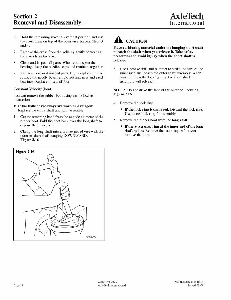
2. Clamp the long shaft into a bronze-jawed vise with the outer or short shaft hanging DOWNWARD. Figure 2.16.
CAUTIONPlace cushioning material under the hanging short shaft to catch the shaft when you release it. Take safety precautions to avoid injury when the short shaft is released.
3. Use a bronze drift and hammer to strike the face of the inner race and loosen the outer shaft assembly. When you compress the locking ring, the short shaft assembly will release.
NOTE: Do not strike the face of the outer bell housing. Figure 2.16.
4. Remove the lock ring.
� If the lock ring is damaged: Discard the lock ring. Use a new lock ring for assembly.
5. Remove the rubber boot from the long shaft.
� If there is a snap ring at the inner end of the long shaft spline: Remove the snap ring before you remove the boot.
Figure 2.16
5000072a
Maintenance Manual 9J Copyright 2008Issued 09-08 AxleTech International Page 15
Section 3Prepare Parts for Assembly
Maintenance Manual 9J Copyright 2003Issued 08-03 AxleTech International Page 15
Section 3 Prepare Parts for Assembly
WARNINGTo prevent serious eye injury, always wear safe eye protection when you perform vehicle maintenance or service.
Solvent cleaners can be flammable, poisonous and cause burns. Examples of solvent cleaners are carbon tetrachloride, and emulsion-type and petroleum-base cleaners. Read the manufacturer’s instructions before using a solvent cleaner, then carefully follow the instructions. Also follow the procedures below.
� Wear safe eye protection.
� Wear clothing that protects your skin.
� Work in a well-ventilated area.
� Do not use gasoline, or solvents that contain gasoline. Gasoline can explode.
� You must use hot solution tanks or alkaline solutions correctly. Read the manufacturer’s instructions before using hot solution tanks and alkaline solutions. Then carefully follow the instructions.
Clean Ground and Polished Parts1. Use a cleaning solvent to clean ground or polished
parts or surfaces. Kerosene or diesel fuel oil can be used for this purpose. DO NOT USE GASOLINE.
2. Use a tool with a flat blade if required, to remove sealant material from parts. Be careful not to damage the polished or smooth surfaces.
CAUTIONDo not use hot solution tanks or water and alkaline solutions to clean ground or polished parts. Damage to parts can result.
3. Do not clean ground or polished parts with water or steam. Do not immerse ground or polished parts in a hot solution tank or use strong alkaline solutions for cleaning, or the smooth sealing surface may be damaged.
Clean Rough Parts1. Clean rough parts with the same method as cleaning
ground and polished parts.
2. Rough parts can be cleaned in hot solution tanks with a weak or diluted alkaline solution.
3. Parts must remain in hot solution tanks until heated and completely cleaned.
4. Parts must be washed with water until all traces of the alkaline solution are removed.
Clean Axle Assemblies1. A complete axle assembly can be steam cleaned on the
outside to remove dirt.
2. Before the axle is steam cleaned, close or place a cover over all openings in the axle assembly. Examples of openings are breathers or vents in air chambers.
Dry Parts After Cleaning1. Parts must be dried immediately after cleaning and
washing.
2. Dry the parts using soft, clean paper or cloth rags.
CAUTIONDamage to bearings can result when they are rotated and dried with compressed air.
3. Except for bearings, parts can be dried with compressed air.
Prevent Corrosion on Cleaned Parts1. Apply axle lubricant to cleaned and dried parts that are
not damaged and are to be assembled.
2. To store parts, apply a special material that prevents corrosion to all surfaces. Wrap cleaned parts in a special paper that will protect the parts from moisture and prevent corrosion.
Inspect PartsIt is very important to inspect all parts carefully and completely before the axle or carrier is assembled. Check all parts for wear and replace damaged parts.
Repair or Replace Parts
NOTE: Threads must be without damage and clean so that accurate adjustments and correct torque values can be applied to fasteners and parts.
1. Replace any fastener if the corners of the head are worn.
2. Replace washers if damaged.
3. Replace gaskets, oil seals or grease seals at the time of repair.

Copyright 2008 Maintenance Manual 9JPage 16 AxleTech International Issued 09-08
Section 3Prepare Parts for Assembly
Copyright 2003 Maintenance Manual 9JPage 16 AxleTech International Issued 08-03
4. Clean the parts and apply new silicone gasket material where required when the axle is assembled.
5. Remove nicks, marks and burrs from parts with machined or ground surfaces. Use a fine file, india stone, emery cloth or crocus cloth.
6. Clean and repair the threads of fasteners and holes. Use a die, a tap of the correct size, or a fine file.
CAUTIONRepair of axle housing by welding is not permissible. Damage to components can result.
Do Not Bend or Straighten a Damaged Drive Axle Housing
WARNINGReplace damaged or out-of-specification axle components. Do not bend, repair or recondition axle components by welding or heat-treating. A bent axle beam reduces axle strength, affects vehicle operation and voids AxleTech’s warranty. Serious personal injury and damage to components can result.
Always replace a damaged drive axle housing. Do not bend or straighten a damaged housing, which can misalign or weaken it, and void AxleTech’s warranty.
Removing Fasteners Secured with AdhesiveIf it’s difficult to remove fasteners secured with Dri-Loc®, AxleTech specification 2297-T-4180 or Loctite® 277 adhesive, use the following procedure.
CAUTIONWhen you remove fasteners secured with adhesive, slowly heat the fastener to 350°F (177°C). Do not exceed this temperature, or heat fasteners quickly. Damage to components can result.
1. Heat a fastener for three to five seconds only. Try to loosen the fastener with a wrench. Do not use an impact wrench or hit the fastener with a hammer.
2. Repeat Step 1 until you can remove the fastener.
Install Fasteners
New Fasteners with Pre-Applied Adhesive
NOTE: No drying time is required for fasteners with pre-applied adhesive.
1. Use a wire brush to clean oil and dirt from threaded holes.
2. Install new fasteners with pre-applied adhesive to assemble parts. Do not apply adhesives or sealants to fasteners with pre-applied adhesive, or to fastener holes.
3. Tighten fasteners to the required torque value for that size fastener.
Original or Used Fasteners Using AxleTech Liquid Adhesive 2297-T-4180 or Loctite® 277 Adhesive, or Equivalent
WARNINGTake care when you use Loctite® adhesive to avoid serious personal injury. Read the manufacturer’s instructions before using this product. Follow the instructions carefully to prevent irritation to the eyes and skin.
1. Use a wire brush to clean the oil, dirt and old adhesive from all threads and threaded holes.
2. Apply four or five drops of AxleTech liquid adhesive, Loctite® 277 adhesive, or equivalent, inside each threaded hole or bore. Do not apply adhesive directly to fastener threads. Figure 3.1.
Figure 3.1
1003025a
4 TO 5 DROPSON BORETHREADS
Maintenance Manual 9J Copyright 2008Issued 09-08 AxleTech International Page 17
Section 3Prepare Parts for Assembly
Maintenance Manual 9J Copyright 2003Issued 08-03 AxleTech International Page 17
NOTE: There is no drying time required for AxleTech specification 2297-T-4180 liquid adhesive, Loctite® 277 adhesive, or equivalent.
3. Tighten the fasteners to the required torque value for that size fastener.
Applying Silicone Gasket Material
WARNINGWhen you apply some silicone gasket materials, a small amount of acid vapor is present. To prevent serious personal injury, ensure that the work area is well-ventilated. Read the manufacturer’s instructions before using a silicone gasket material, then carefully follow the instructions. If a silicone gasket material gets into your eyes, follow the manufacturer’s emergency procedures. Have your eyes checked by a physician as soon as possible.
NOTE: The following silicone gasket products or equivalent can be used for AxleTech components.
� Three Bond Liquid Gasket number TB 1216 (Grey)
� Loctite® Ultra Grey RTV 5699 silicone
1. Use a tool with a flat blade, if required, to remove all old gasket material from surfaces.
2. Use a cleaning solvent to clean the surfaces where you will apply silicone gasket material. Remove all oil, grease, dirt and moisture without damaging the mating surfaces.
3. Dry surfaces.
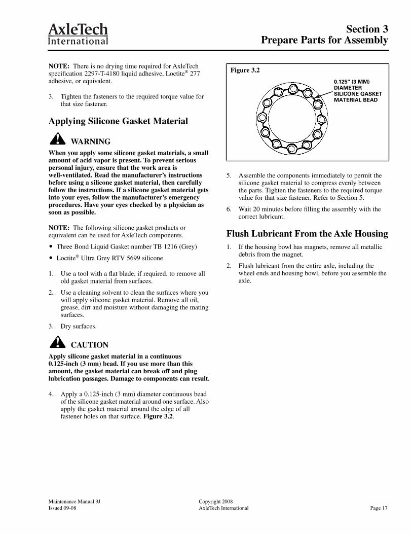
CAUTIONApply silicone gasket material in a continuous 0.125-inch (3 mm) bead. If you use more than this amount, the gasket material can break off and plug lubrication passages. Damage to components can result.
4. Apply a 0.125-inch (3 mm) diameter continuous bead of the silicone gasket material around one surface. Also apply the gasket material around the edge of all fastener holes on that surface. Figure 3.2.
5. Assemble the components immediately to permit the silicone gasket material to compress evenly between the parts. Tighten the fasteners to the required torque value for that size fastener. Refer to Section 5.
6. Wait 20 minutes before filling the assembly with the correct lubricant.
Flush Lubricant From the Axle Housing1. If the housing bowl has magnets, remove all metallic
debris from the magnet.
2. Flush lubricant from the entire axle, including the wheel ends and housing bowl, before you assemble the axle.
Figure 3.2
0.125" (3 MM)DIAMETERSILICONE GASKETMATERIAL BEAD

Copyright 2008 Maintenance Manual 9JPage 18 AxleTech International Issued 09-08
Section 4Assembly and Installation
Copyright 2003 Maintenance Manual 9JPage 18 AxleTech International Issued 08-03
Section 4 Assembly and Installation
WARNINGTo prevent serious eye injury, always wear safe eye protection when you perform vehicle maintenance or service.
Use a brass or leather mallet for assembly and disassembly procedures. Do not hit steel parts with a steel hammer. Pieces of a part can break off and cause serious personal injury.
Assembly of Steering Universal Joint
Round Bearing Yokes or Cardan Joint
NOTE: If you replace the cross, you must replace the needle bearing. Do not mix new and used bearings. Replace in sets of four.
1. Place a needle bearing cap into the ear of the yoke.
2. Use a vise to press the needle bearing cap into the correct position. Do not damage the polished surface of the cap. Figure 4.1.
3. Remove the yoke from the vise. Carefully place one arm of the cross into the yoke and bearing cap.
4. Install the opposite bearing cap into the yoke by hand and align the cross arm.
5. Use the vise to press the bearing cap into the yoke and onto the arm of the cross. Figure 4.2. The cross must move freely in both caps.
� If the cross does not move freely: Remove the cap. Check the alignment of the needle bearings.
6. Use a short plug to push the bearing cups into the yoke past the snap ring grooves. Install the snap rings into the grooves, one in each bearing cap.
7. Repeat Steps 1-7 to install the remaining caps and yokes.
Wing Bearing Yokes
1. If the cross and cap assembly is damaged, replace all the parts with a new assembly.
2. Use the eight capscrews and nuts to attach the cross assembly to the yokes. Tighten the capscrews and jam nuts to the specified torque. Refer to the table below.
Lubricate round and wing bearing style caps with grease. Clean, then apply specified grease until it purges from all four seals.
Grease: NLGI GR2 (Lithium 12-hydroxy stearate with molybdenum disulfide)
Figure 4.1
5000067a
Figure 4.2
Fastener Size
Torque lb-ft (N•m)
Capscrews Jam Nuts
7/16"-20 70-80 (95-108) 20-30 (27-41)
1/2"-20 115-135 (155-183) 27-37 (36-50)
5000068a

Maintenance Manual 9J Copyright 2008Issued 09-08 AxleTech International Page 19
Section 4Assembly and Installation
Maintenance Manual 9J Copyright 2003Issued 08-03 AxleTech International Page 19
Constant Velocity Joint
NOTE: AxleTech kit number MPS 4707 is available for the PSC205 axle model. The kit contains a new boot, outer lock ring, stainless strapping and a lock clip for one shaft assembly. To obtain this kit, refer to the Service Notes page on the front inside cover of this manual.
1. Inspect the constant velocity joint bell housing and race assembly for the correct amount of grease (approximately 12 ounces). The grease level should be at the back side of the inner race as viewed through the internal spline of the inner race.
NOTE: Grease should be placed around each ball in race and into boot fold cavities, NOT packed near boot/axle shaft journal as some seepage could occur. If necessary, remove contaminants and add Shell Alvania EP-2 grease or equivalent.
2. Clean the outside of the bell housing and boot groove area.
3. Clean old grease and debris from the spline area and boot sealing area of the inner or long axle shaft. Inspect the splines, lock ring grooves and lock rings.
4. Apply a light film of EP-2 grease to the shaft seat diameter for the boot. Use hand pressure to install the new boot on the shaft seating diameter. Figure 4.3.
5. Install the inner, if equipped, and outer lock rings in the grooves of the long shaft. Figure 4.3.
6. Use a bronze-jawed vise to hold the short shaft, bell housing and ball races. Position the open end of the bell housing UPWARD.
7. Install the long shaft and boot assembly, with the lock rings in the grooves, into the inner race until the lock ring contacts the chamfer of the inner race.
8. Have a second person use a blunt-edged tool, such as a flat-blade screwdriver, to depress the lock ring into the groove while you push the long shaft partially into the inner race. Use a plastic mallet, or a mallet and bronze drift, to strike the end of the long shaft and drive the shaft through the inner race. The lock ring must clear the inner race and expand to lock the shaft into position.
9. Verify that the long shaft is correctly seated by lightly pulling OUTWARD on the long shaft. The lock ring should resist outward movement. Do not use excessive force to perform this test.
10. Position the large end of the boot, with the raised circumference seat in the inside diameter of the boot, into the external groove of the bell housing. The boot seat and the groove must be clean and dry. Do not use sealer or adhesive.
11. Install 1/4-inch stainless steel strapping with a clip around the boot outside diameter, over the boot groove seating area. Use Band-It® brand strapping and the clip from the kit.
12. Use the Band-It® brand ratchet tool, Pok-It II tool number J020 or equivalent, to tighten the strapping. The boot material must be compressed and puckered under the strap. The strap must be positioned over the bell housing groove.
CAUTIONDo not use excessive hammer force to flatten the clip ears over the strap end. Damage to the strap, buckle or boot can occur from excessive hammer force. Take care not to create a tear in boot material when tightening the strap/clip assembly.
13. Verify that the boot and strap are positioned correctly. Use a hammer to flatten the clip ears over the strap end to lock it in. Do not use excessive hammer force to flatten the clip ears. Damage to the strap, buckle or boot can occur.
14. Remove the assembly from the vise. Verify that the constant velocity joint is operating correctly and the boot strapping is holding correctly.
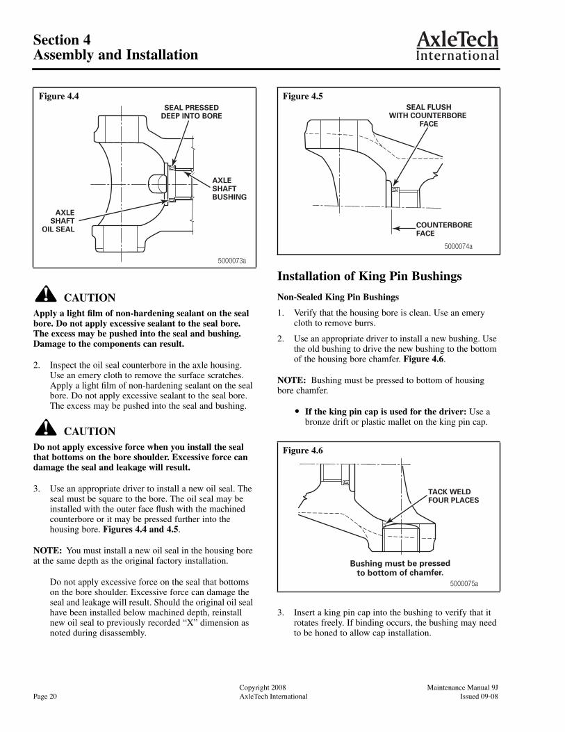
Installation of Axle Shaft Bushing and Seal 1. Use an appropriate driver to install a new axle shaft
bushing in the axle housing. The bushing must be flush with the oil seal counterbore. Figure 4.4.
Figure 4.3
5000069a
INNER LOCK RING(SOME VERSIONS)
OUTER LOCKRING
BOOTINNER (LONG)
SHAFT
Copyright 2008 Maintenance Manual 9JPage 20 AxleTech International Issued 09-08
Section 4Assembly and Installation
Copyright 2003 Maintenance Manual 9JPage 20 AxleTech International Issued 08-03
CAUTIONApply a light film of non-hardening sealant on the seal bore. Do not apply excessive sealant to the seal bore. The excess may be pushed into the seal and bushing. Damage to the components can result.
2. Inspect the oil seal counterbore in the axle housing. Use an emery cloth to remove the surface scratches. Apply a light film of non-hardening sealant on the seal bore. Do not apply excessive sealant to the seal bore. The excess may be pushed into the seal and bushing.
CAUTIONDo not apply excessive force when you install the seal that bottoms on the bore shoulder. Excessive force can damage the seal and leakage will result.
3. Use an appropriate driver to install a new oil seal. The seal must be square to the bore. The oil seal may be installed with the outer face flush with the machined counterbore or it may be pressed further into the housing bore. Figures 4.4 and 4.5.
NOTE: You must install a new oil seal in the housing bore at the same depth as the original factory installation.
Do not apply excessive force on the seal that bottoms on the bore shoulder. Excessive force can damage the seal and leakage will result. Should the original oil seal have been installed below machined depth, reinstall new oil seal to previously recorded “X” dimension as noted during disassembly.
Installation of King Pin Bushings
Non-Sealed King Pin Bushings
1. Verify that the housing bore is clean. Use an emery cloth to remove burrs.
2. Use an appropriate driver to install a new bushing. Use the old bushing to drive the new bushing to the bottom of the housing bore chamfer. Figure 4.6.
NOTE: Bushing must be pressed to bottom of housing bore chamfer.
� If the king pin cap is used for the driver: Use a bronze drift or plastic mallet on the king pin cap.
3. Insert a king pin cap into the bushing to verify that it rotates freely. If binding occurs, the bushing may need to be honed to allow cap installation.
Figure 4.4SEAL PRESSED
DEEP INTO BORE
AXLESHAFTBUSHING
AXLESHAFT
OIL SEAL
5000073a
Figure 4.5
Figure 4.6
SEAL FLUSHWITH COUNTERBORE
FACE
COUNTERBOREFACE
5000074a
5000075a
TACK WELDFOUR PLACES
Bushing must be pressedto bottom of chamfer.

Maintenance Manual 9J Copyright 2008Issued 09-08 AxleTech International Page 21
Section 4Assembly and Installation
Maintenance Manual 9J Copyright 2003Issued 08-03 AxleTech International Page 21
4. Install a new expansion plug with the convex side TOWARD the axle centerline. Hit the center of the expansion plug to slightly deform and expand the plug until it is tight in the bore. If necessary, grind off excess metal from the original tack welds to allow the new plug to be installed.
5. Tack weld the expansion plug to the housing in four places. The plug must fit tightly in the housing bore to prevent king pin bushing grease from leaking. Figure 4.6.
Sealed King Pin Bushings
WARNINGTake care when you use Loctite® adhesive to avoid serious personal injury. Read the manufacturer’s instructions before using this product. Follow the instructions carefully to prevent irritation to the eyes and skin.
1. Verify that the housing bore is clean. Use an emery cloth to remove burrs.
2. Check the fit of the new bushing in the housing bore.
� If the bushing is not tight and slides into the housing bore with hand pressure: Use a brush to apply a thin coat of Loctite® 680 sealant or equivalent to the housing bore or to the bushing outside diameter near the closed end. Do not allow any sealant to contact the bushing grooved face where the king pin will contact the bushing. Install the bushing into the housing bore until the flange is tightly seated on the housing boss face. Figure 4.7.
� If the bushing is tight in the housing bore: Insert a king pin cap in the bushing. Use a plastic mallet or bronze drift on the cap to drive the bushing into the housing. Drive the bushing into the bore until the bushing flange is tightly seated on the housing boss face. Figure 4.7.
NOTE: Kit “MPS4470” has KP bushings, KP caps, grease seals, grease fittings, and shims for 2 wheel ends of the PSC1485 axle.Kit “MPS4465” has KP bushing, KP cap, grease seal, grease fitting and shims for one king pin location of the PSC1485 axle.Kit “MPS4476” has “oversize” KP bushings, KP caps, grease seals, grease fittings, shims, and re-work instruction for PSC1485 axle where the housing bore for KP bushing is worn (up to 1.452 in. R. maximum).
Assembly of Steer Knuckle
1. Use AxleTech specification number O-617-A or O-617-B grease to lubricate the king pin bushing bores. For flanged bushings, also lubricate the thrust faces.
WARNINGTake care when you use lifting devices. When you use a lifting strap, inspect the strap for damage before you use it. Do not use a lifting strap to shock load or drop load a component. Serious personal injury and damage to components can result.
2. Use a lifting device to install the knuckle over the axle housing trunnion end. Align the king pin bore in the knuckle with the axle housing king pin bushing. Figure 4.8.
Figure 4.7FLANGEDBUSHING
SEALED DESIGN5000070a

Copyright 2008 Maintenance Manual 9JPage 22 AxleTech International Issued 09-08
Section 4Assembly and Installation
Copyright 2003 Maintenance Manual 9JPage 22 AxleTech International Issued 08-03
Figure 4.8
1. Planetary Spider 8. Steer Knuckle Tie Rod Nut Cotter Pin
2. Wheel Hub 9. Steer Knuckle Tie Rod Assembly with Ball Stud Ends
3. Upper King Pin Capscrews (4) 10. Lower King Pin Cap Thrust Washer or Grease Seal
4. Upper King Pin Cap 11. Lower King Pin Cap Shims
5. Upper King Pin Cap Shims 12. Lower King Pin Capscrews (4)
6. Steer Knuckle 13. Lower King Pin Cap
7. Steer Knuckle Tie Rod Assembly Nut 14. Axle Housing
5000057a
33
4
5
6
1
2
1312
11
10
8
714
9
Maintenance Manual 9J Copyright 2008Issued 09-08 AxleTech International Page 23
Section 4Assembly and Installation
Maintenance Manual 9J Copyright 2003Issued 08-03 AxleTech International Page 23
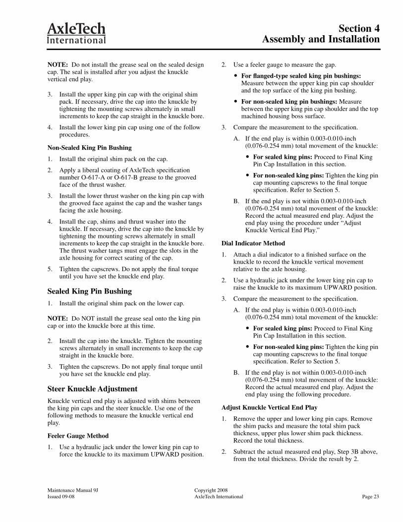
NOTE: Do not install the grease seal on the sealed design cap. The seal is installed after you adjust the knuckle vertical end play.
3. Install the upper king pin cap with the original shim pack. If necessary, drive the cap into the knuckle by tightening the mounting screws alternately in small increments to keep the cap straight in the knuckle bore.
4. Install the lower king pin cap using one of the follow procedures.
Non-Sealed King Pin Bushing
1. Install the original shim pack on the cap.
2. Apply a liberal coating of AxleTech specification number O-617-A or O-617-B grease to the grooved face of the thrust washer.
3. Install the lower thrust washer on the king pin cap with the grooved face against the cap and the washer tangs facing the axle housing.
4. Install the cap, shims and thrust washer into the knuckle. If necessary, drive the cap into the knuckle by tightening the mounting screws alternately in small increments to keep the cap straight in the knuckle bore. The thrust washer tangs must engage the slots in the axle housing for correct seating of the cap.
5. Tighten the capscrews. Do not apply the final torque until you have set the knuckle end play.
Sealed King Pin Bushing
1. Install the original shim pack on the lower cap.
NOTE: Do NOT install the grease seal onto the king pin cap or into the knuckle bore at this time.
2. Install the cap into the knuckle. Tighten the mounting screws alternately in small increments to keep the cap straight in the knuckle bore.
3. Tighten the capscrews. Do not apply final torque until you have set the knuckle end play.
Steer Knuckle Adjustment
Knuckle vertical end play is adjusted with shims between the king pin caps and the steer knuckle. Use one of the following methods to measure the knuckle vertical end play.
Feeler Gauge Method
1. Use a hydraulic jack under the lower king pin cap to force the knuckle to its maximum UPWARD position.
2. Use a feeler gauge to measure the gap.
� For flanged-type sealed king pin bushings: Measure between the upper king pin cap shoulder and the top surface of the king pin bushing.
� For non-sealed king pin bushings: Measure between the upper king pin cap shoulder and the top machined housing boss surface.
3. Compare the measurement to the specification.
A. If the end play is within 0.003-0.010-inch (0.076-0.254 mm) total movement of the knuckle:
� For sealed king pins: Proceed to Final King Pin Cap Installation in this section.
� For non-sealed king pins: Tighten the king pin cap mounting capscrews to the final torque specification. Refer to Section 5.
B. If the end play is not within 0.003-0.010-inch (0.076-0.254 mm) total movement of the knuckle: Record the actual measured end play. Adjust the end play using the procedure under “Adjust Knuckle Vertical End Play.”
Dial Indicator Method
1. Attach a dial indicator to a finished surface on the knuckle to record the knuckle vertical movement relative to the axle housing.
2. Use a hydraulic jack under the lower king pin cap to raise the knuckle to its maximum UPWARD position.
3. Compare the measurement to the specification.
A. If the end play is within 0.003-0.010-inch (0.076-0.254 mm) total movement of the knuckle:
� For sealed king pins: Proceed to Final King Pin Cap Installation in this section.
� For non-sealed king pins: Tighten the king pin cap mounting capscrews to the final torque specification. Refer to Section 5.
B. If the end play is not within 0.003-0.010-inch (0.076-0.254 mm) total movement of the knuckle: Record the actual measured end play. Adjust the end play using the following procedure.
Adjust Knuckle Vertical End Play
1. Remove the upper and lower king pin caps. Remove the shim packs and measure the total shim pack thickness, upper plus lower shim pack thickness. Record the total thickness.
2. Subtract the actual measured end play, Step 3B above, from the total thickness. Divide the result by 2.

Copyright 2008 Maintenance Manual 9JPage 24 AxleTech International Issued 09-08
Section 4Assembly and Installation
Copyright 2003 Maintenance Manual 9JPage 24 AxleTech International Issued 08-03
3. Adjust the lower shim pack thickness to equal the value determined in Step 2. If the exact thickness cannot be obtained, choose the nearest thicker pack.
4. Adjust the upper shim pack thickness to equal the value determined in Step 2 plus 0.005-inch (0.127 mm).
Example
Actual end play = 0.020-inch (0.508 mm)
Total shim pack thickness = 0.066-inch(1.676 mm)
0.066 – 0.020 = 0.046-inch (1.676 – 0.508 = 1.168 mm)
0.046 divided by 2 = 0.023-inch (1.168 divided by 2 = 0.584 mm)
New lower shim pack thickness = 0.023-inch (0.584 mm)
New upper shim pack thickness = 0.023 + 0.005 = 0.028-inch (0.584 + 0.127 = 0.711 mm)
5. Proceed to Final King Pin Cap Installation in this section.
Final King Pin Cap Installation
Sealed King Pin
1. Install the grease seal.
� For cap-piloted seals: Install the seal on the upper and lower king pin cap.
� For knuckle-piloted seals: Install the seal in the knuckle bore.
2. Install the new shim packs on the upper and lower caps.
3. Install the upper cap assembly into the knuckle. Use the mounting capscrews to drive the cap into the knuckle. Tighten the capscrews alternately in small increments to keep the cap straight in the knuckle bore. The cap will push the knuckle-piloted grease seal to its final position in the bore. For torque specifications, refer to Section 5.
4. Repeat Step 3 to install the lower cap assembly into the knuckle.
5. Grease the upper and lower bushings through the grease fitting in the king pin cap. Apply grease until it flows from the grease seal.
Non-Sealed King Pin
1. Install the new shim pack on the upper king pin cap.
2. Install the upper king pin cap into the knuckle. Use the mounting capscrews to drive the cap into the knuckle. Tighten the capscrews alternately in small increments to keep the cap straight in the knuckle bore. For torque specifications, refer to Section 5.
3. Install the new shim pack on the lower king pin cap.
4. Grease the grooved face of the lower thrust washer. Place the washer on the king pin cap with the grooved face contacting the king pin cap surface.
CAUTIONThe thrust washer tangs must engage the slots in the axle housing. If the tangs are not correctly engaged in the slots, damage to components will result.
5. Install the lower cap, shim pack and thrust washer into the knuckle. The thrust washer tangs must engage the slots in the axle housing. Use the mounting capscrews to drive the cap into the knuckle. Tighten the capscrews alternately in small increments to keep the cap straight in the knuckle bore.
6. Tighten the capscrews to the correct torque specification after confirming that the thrust washer is correctly oriented. For torque specifications, refer to Section 5.
7. Grease the upper and lower king pin bushings through the grease fitting in the king pin cap. The lower thrust washer grooved face may not receive grease unless the knuckle assembly is pushed UPWARD, such as when the axle is supporting the vehicle with the tire on the ground.
Axle Components
1. Connect the tie rod to the knuckle. For torque specifications, refer to Section 5.
2. Connect the power steering cylinder to the knuckle. Refer to the vehicle manufacturer’s procedures for torque specifications.
3. Install brake-related components as necessary.
Axle Shaft and Universal Joint
The following procedure applies to shafts with either the cardan universal joint or the constant velocity joint.
1. Apply AxleTech specification number O-617-A or O-617-B grease to the oil seal lip and bushing in the axle housing.
Maintenance Manual 9J Copyright 2008Issued 09-08 AxleTech International Page 25
Section 4Assembly and Installation
Maintenance Manual 9J Copyright 2003Issued 08-03 AxleTech International Page 25
2. Apply grease to the seal journals on the axle shaft assembly.
3. Insert the axle shaft assembly into the housing until it engages the side gear of the differential. Use care to avoid damage to the oil seal when you install the shaft.
Spindle, Brake and Planetary Wheel End
Refer to the appropriate planetary wheel end maintenance manual for spindle, brake and planetary wheel end installation procedures.
For measuring and adjusting the toe setting procedures, refer to the following publications.
� Maintenance Manual 9C, Planetary Rigid and Steer Axle Wheel Ends, Cantilever-Mounted Planetary Pinion Shaft Design
� Maintenance Manual 9E, Planetary Axle Wheel Ends, Covered Planetary Spider Design
� Maintenance Manual 9G, Planetary Axle Wheel Ends, Coverless Planetary Spider Design
For lubrication information, refer to the following publications.
� Maintenance Manual 1, Lubrication
� Maintenance Manual 9C, Planetary Rigid and Steer Axle Wheel Ends, Cantilever-Mounted Planetary Pinion Shaft Design
� Maintenance Manual 9E, Planetary Axle Wheel Ends, Covered Planetary Spider Design
� Maintenance Manual 9G, Planetary Axle Wheel Ends, Coverless Planetary Spider Design
To obtain these publications, refer to the Service Notes page on the front inside cover of this manual.

Copyright 2008 Maintenance Manual 9JPage 26 AxleTech International Issued 09-08
Section 5Torque Specifications
Copyright 2003 Maintenance Manual 9JPage 26 AxleTech International Issued 08-03
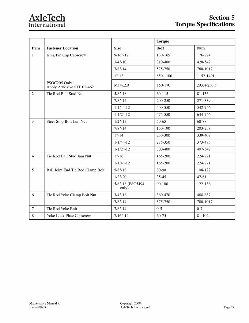
Section 5 Torque Specifications Refer to Figure 5.1, Figure 5.2 and Figure 5.3.
Figure 5.1
Figure 5.2
Figure 5.3
1 4
1
5000076a
3
2
1
5000077a
3
2
51
A
A
5000078a
D
1
176
8
3
Maintenance Manual 9J Copyright 2008Issued 09-08 AxleTech International Page 27
Section 5Torque Specifications
3002 thgirypoCJ9 launaM ecnanetniaM72 egaPlanoitanretnI hceTelxA30-80 deussI
Item Fastener Location Size
Torque
lb-ft N•m
1 King Pin Cap Capscrew 9/16"-12 130-165 176-224
3/4"-10 310-400 420-542
7/8"-14 575-750 780-1017
1"-12 850-1100 1152-1491
M14x2.0 150-170 203.4-230.5
2 Tie Rod Ball Stud Nut 5/8"-18 60-115 81-156
7/8"-14 200-250 271-339
1-1/4"-12 400-550 542-746
1-1/2"-12 475-550 644-746
3 Steer Stop Bolt Jam Nut 1/2"-13 50-65 68-88
7/8"-14 150-190 203-258
1"-14 250-300 339-407
1-1/4"-12 275-350 373-475
1-1/2"-12 300-400 407-542
4 Tie Rod Ball Stud Jam Nut 1"-16 165-200 224-271
1-1/4"-12 165-200 224-271
5 Ball Joint End Tie Rod Clamp Bolt 5/8"-18 80-90 108-122
1/2"-20 35-45 47-61
5/8"-18 (PSC5494 only)
90-100 122-136
6 Tie Rod Yoke Clamp Bolt Nut 3/4"-16 360-470 488-637
7/8"-14 575-750 780-1017
7 Tie Rod Yoke Bolt 7/8"-14 0-5 0-7
8 Yoke Lock Plate Capscrew 7/16"-14 60-75 81-102
PSOC205 Only Apply Adhesive STF 02-462

Copyright 2008 Maintenance Manual 9JPage 28 AxleTech International Issued 09-08
Section 6Lubrication Specifications
Copyright 2003 Maintenance Manual 9JPage 28 AxleTech International Issued 08-03
Section 6Lubrication SpecificationsTable A: Typical Axle Housing Oil Capacities for Planetary Steer Axle Models (1)
(1) Typical lube quantities are indicated as estimates due to the multiple axle housing length options available. Actual volumes required for the specific axle being serviced should be verified by using the recommended oil fill procedure.
Axle Model
Axle Housing Lube Capacity (Estimated)
Pints Liters
PSS165 20 9.5
PSS166 20 9.5
PSC204 29 13.7
PSC205 29 13.7
PSOC205 29 13.7
PSC353 25 11.8
PSC594 28 13.2
PSC822
PSC824 30 14.2
PSTC824 30 14.2
PSC825 30 14.2
PSC826 37 17.5
PSC1044 40 18.9
PSC1045 40 18.9
PSC1485 44 20.8
PSC1614 40 18.9
PSC1615 40 18.9
PSC1617 40 18.9
PSC1764 40 18.9
PSC1794(R155) 52 24.6
PSC1794(RS160)
PSC1875 56 26.4
PSC1876 54 25.5
PSC4564 58 27.4
PSC4565 58 27.4
PSC5494 64 30.2

Notes

Notes


MM9JIssued 09-08
© Copyright AxleTech InternationalPrinted in the USA
Suite 4003001 West Big Beaver RoadTroy, Michigan 48084U.S.A.Toll Free: 877-877-9717Non-Toll Free: 248-816-5401FAX: 248-435-1990Website: www.axletech.com
AxleTech, International France4, Rue Jean ServantonBoite Postale 65642042 Saint Etienne Cedex 1France(33) 477.92.88.00FAX: (33) 477.92.88.93
AxleTech do Brasil Sistemas Automotivos Ltda.Avendia Joao Batista, 830Centro-Osasco-SP06097095 BrasilPhone: +55 11 36846641FAX: +55 11 36846859