planar surface gantries excm - festo.com · 3 proximity sensor sies-8m 50 4 drive package...
TRANSCRIPT

Planar surface gantries EXCM

Subject to change – 2018/092 � Internet: www.festo.com/catalogue/...
Planar surface gantries EXCMFeatures
At a glance
General remarks Sample applications
� A gantry that is characterised by
high functionality in compact
installation spaces
� The drive concept provides a low
moving mass.
� Perfectly matching drive and
controller package
� The kinematics are actuated via
2 stepper motors with integrated
optical encoder (closed loop) and
one matching two-axis controller
� Can be actuated using two
operating modes:
– Direct mode via Ethernet and
CAN
– Record selection via digital I/O,
Ethernet and CAN
� Permits flexible motor mounting
� Feeding, pressing, joining
components
� Dispensing liquid media
� Mounting electronic components
EXCM-30 EXCM-40
Operating principle
A slide is moved in a two-dimensional
space (X-axis/Y-axis) via a toothed
belt. The system is powered via 2 fixed
motors in position-controlled
operation (closed loop). The motors
are coupled to the toothed belt. The
belt is guided via guide pulleys so that
the slide can move to any position in a
working space when the motors are
actuated accordingly.
Motor 1
Mot
or 2
Motor 1 Motor 2Y-axis
X-ax
is
Motor 1
X-ax
is
Motor 2
EXCM-30 EXCM-40
Y-axis

2018/09 – Subject to change 3� Internet: www.festo.com/catalogue/...
Planar surface gantries EXCMKey features
Planar surface gantry
Type EXCM-30 EXCM-40
Guide Recirculating ball bearing guide Recirculating ball bearing guide
Stroke of the
X-axis [mm] 100, 150, 200, 300, 400, 500 –
90 … 700 200 … 2000
Y-axis [mm] 110, 160, 210, 260, 310, 360, 410, 460, 510 –
110 … 510 200 … 1000
Rated load for max. dynamic response1) [kg] 2/32) 4
Repetition accuracy [mm] ±0.05 ±0.1
Mounting position Any Horizontal
Controller Separate Separate
Further technical data � page 6 � page 22
1) Rated load = tool load (attachment components) + payload
2) Vertical/horizontal mounting position
Controller
For planar surface gantry EXCM-30 EXCM-40
Can be ordered through modular product system EXCM-…-E
Load voltage [V DC] 24 –
Nominal current [A] 6 –
Switching logic NPN –
Configuration support FCT (Festo Configuration Tool) with plug-in EXCM –
Technical data � page 41 –
Can be ordered through modular product system EXCM-…-PF
Load voltage [V DC] 48 or 24 48
Nominal current [A] 10
Switching logic PNP
Safety function to EN 61800-5-2 Safe torque off (STO)
Configuration support FCT (Festo Configuration Tool) with plug-in CMXH
Technical data � Internet: cmxh
FCT software – Festo Configuration Tool
Software platform for electric drives from Festo Record table
� All drives in a system can be
managed and saved in a common
project
� Project and data management for
all supported type of equipment
� Easy to use thanks to graphically
supported parameter entry
� Universal mode of operation for all
drives
� Work offline at your desk or online
at the machine
� 31 records ensure flexible
positioning
� The following parameters can be set
flexibly for each application:
– Position
– Speed
– Acceleration
– Return (only with controller
CMXH)
� Absolute or relative positioning
values can be used
� Complete performance test
Subject to change – 2018/094 � Internet: www.festo.com/catalogue/...
Planar surface gantries EXCMKey features
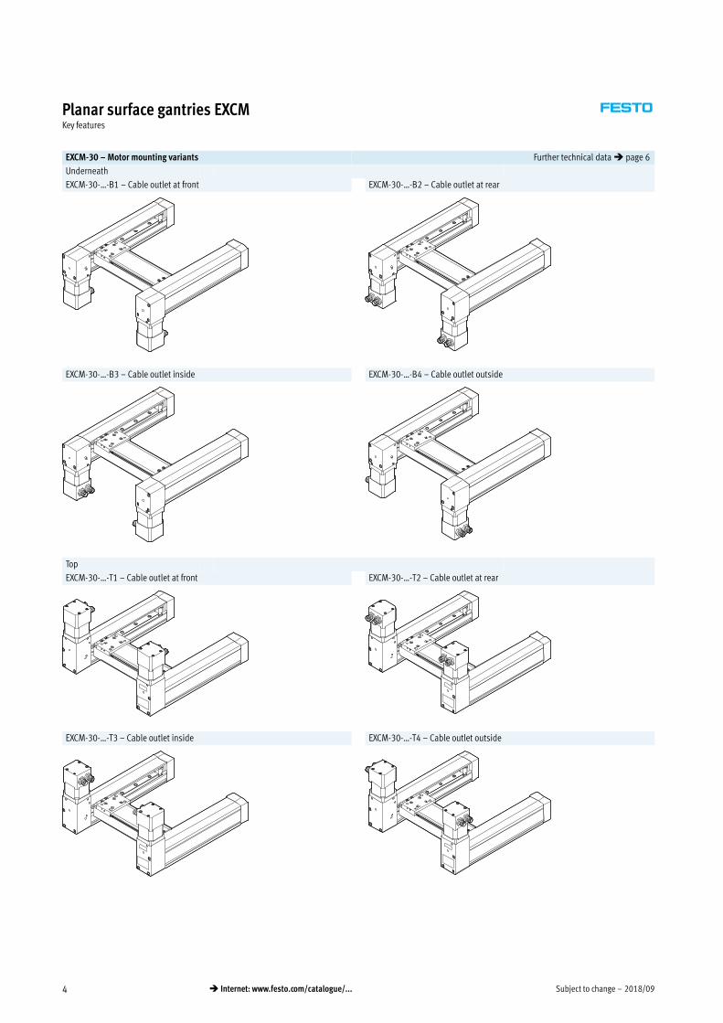
EXCM-30 – Motor mounting variants Further technical data � page 6
Underneath
EXCM-30-…-B1 – Cable outlet at front EXCM-30-…-B2 – Cable outlet at rear
EXCM-30-…-B3 – Cable outlet inside EXCM-30-…-B4 – Cable outlet outside
Top
EXCM-30-…-T1 – Cable outlet at front EXCM-30-…-T2 – Cable outlet at rear
EXCM-30-…-T3 – Cable outlet inside EXCM-30-…-T4 – Cable outlet outside

2018/09 – Subject to change 5� Internet: www.festo.com/catalogue/...
Planar surface gantries EXCMKey features
EXCM-40 – Motor mounting variants Further technical data � page 22
EXCM-40-…-B – Motor underneath
EXCM-40-…-T – Motor on top

Subject to change – 2018/096 � Internet: www.festo.com/catalogue/...
Planar surface gantries EXCM-30Type codes
EXCM — 30 — 300 — 210 — KF — ST — — B1
Type
EXCM Planar surface gantry
Size
Stroke of the X-axis [mm]
Stroke of the Y-axis [mm]
Guide
KF Recirculating ball bearing guide
Motor type
ST Stepper motors
SB Stepper motors with brake
W Without stepper motors
Protection against particles
– Standard
P8 Protected version
Motor attachment position
B Underneath
B1 Underneath, cable outlets to the front
B2 Underneath, cable outlets to the rear
B3 Underneath, cable outlets inwards
B4 Underneath, cable outlets outwards
T Top
T1 On top, cable outlets to the front
T2 On top, cable outlets to the rear
T3 On top, cable outlets inwards
T4 On top, cable outlets outwards
2018/09 – Subject to change 7� Internet: www.festo.com/catalogue/...
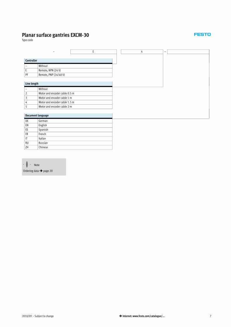
Planar surface gantries EXCM-30Type code
– E 4 —
Controller
– Without
E Remote, NPN (24 V)
PF Remote, PNP (24/48 V)
Line length
– Without
2 Motor and encoder cable 0.5 m
3 Motor and encoder cable 1 m
4 Motor and encoder cable 1.5 m
5 Motor and encoder cable 2 m
Document language
DE German
EN English
ES Spanish
FR French
IT Italian
RU Russian
ZH Chinese
-H- Note
Ordering data � page 20

Subject to change – 2018/098 � Internet: www.festo.com/catalogue/...
Planar surface gantries EXCM-30Peripherals overview
aJ
2
2
2
3
4
4
4
4
4
5
6
17
8
9
aA
Variants and accessories
1 With protection against particles EXCM-…-P8 2 With adjusting kit EADC-E11
The cover protects the guide of the Y-axis against contamination. With the adjusting kit, the gantry can be aligned after installation.
1
2

2018/09 – Subject to change 9� Internet: www.festo.com/catalogue/...
Planar surface gantries EXCM-30Peripherals overview
Accessories
Type Description � Page/Internet
1 Profile mounting
MUE
Included in the scope of delivery of the planar surface gantry:
� X-stroke 500 mm: 2 pairs
� X-stroke 500 mm: 3 pairs
44
2 Sensor mounting
EAPR
For homing in combination with third-party motors 46
3 Proximity sensor
SIES-8M
50
4 Drive package comprising controller,
motor, motor cable
Available with or without drive package 20
5 Control cable
NEBC-S1H15
For the I/O interface to any controller 51
6 Plug connector Included in the scope of delivery of the drive package –
7 Energy chain
EADH-U-3D
For the cable routing of the Z-axis 47
8 Connection set Holder for mounting the energy chain
Included in the scope of delivery:
� 2 connectors
� 4 socket head screws M4x10
47
9 Mounting kit
EAHT-E9
Mounting kit for the energy chain and a Z-axis, like EGSL, DGSL, EGSK
Stroke reduction in combination with mounting kit EAHT � page 15
45
aJ Adjusting kit
EADC-E11
Height-adjustable mounting kit 44
aA H-rail mounting
CAFM-D3
For mounting the controller to an H-rail to EN 50022 43
-H- Note
Homing is always carried out using
the mechanical stop in combination
with the drive package from Festo; the
sensor mounting and proximity
sensor are not required in this case.

Subject to change – 2018/0910 � Internet: www.festo.com/catalogue/...
Planar surface gantries EXCM-30Technical data
General technical data
Design Planar surface gantry
Guide Recirculating ball bearing guide
Stroke of the
X-axis [mm] 100, 150, 200, 300, 400, 500
90 … 700
Y-axis [mm] 110, 160, 210, 260, 310, 360, 410, 460, 510
110 … 510
Rated load for max. dynamic response1) [kg] 2/32)
Max. process force3) [N] 100
Max. torque � page 12
Max. no-load torque � page 12
Nominal torque of motor [Nm] 0.5
Motor holding torque [Nm] 0.5
Max. acceleration
EXCM-…-E [m/s2] 10
EXCM-…-PF [m/s2] 20/104)
Max. speed
EXCM-…-E [m/s] 0.5
EXCM-…-SB-…-PF [m/s] 0.5
EXCM-…-ST-…-PF [m/s] 1.0/0.54)
Repeat accuracy [mm] ±0.05
Mounting position Any5)
Type of mounting
Planar surface gantry With profile mounting
Controller Via H-rail, on base plate
1) Rated load = tool load (attachment components) + payload
2) Vertical/horizontal mounting position. Applies to EXCM-…-E with stroke of the Y-axis of 360 mm � page 11
3) Perpendicular to working plane, at standstill
4) In case of a load supply of 48 V/24 V
5) Motors with brake must be used in the case of vertical installation
Operating and environmental conditions
Degree of protection IP20
Ambient temperature [°C] +10 … +45
Storage temperature [°C] –10 … +60
Relative humidity [%] 0 … 90 (non-condensing)
Noise level [dB(A)] 52
Duty cycle [%] 100
CE marking (see declaration of conformity) To EU Machinery Directive
2018/09 – Subject to change 11� Internet: www.festo.com/catalogue/...
Planar surface gantries EXCM-30Technical data
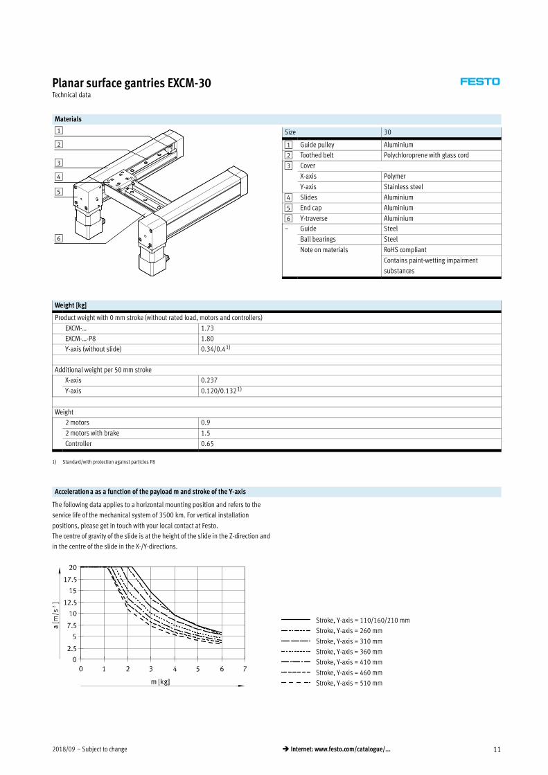
Materials
Size 30
1 Guide pulley Aluminium
2 Toothed belt Polychloroprene with glass cord
3 Cover
X-axis Polymer
Y-axis Stainless steel
4 Slides Aluminium
5 End cap Aluminium
6 Y-traverse Aluminium
– Guide Steel
Ball bearings Steel
Note on materials RoHS compliant
Contains paint-wetting impairment
substances
Weight [kg]
Product weight with 0 mm stroke (without rated load, motors and controllers)
EXCM-… 1.73
EXCM-…-P8 1.80
Y-axis (without slide) 0.34/0.41)
Additional weight per 50 mm stroke
X-axis 0.237
Y-axis 0.120/0.1321)
Weight
2 motors 0.9
2 motors with brake 1.5
Controller 0.65
1) Standard/with protection against particles P8
Acceleration a as a function of the payload m and stroke of the Y-axis
The following data applies to a horizontal mounting position and refers to the
service life of the mechanical system of 3500 km. For vertical installation
positions, please get in touch with your local contact at Festo.
The centre of gravity of the slide is at the height of the slide in the Z-direction and
in the centre of the slide in the X-/Y-directions.
Stroke, Y-axis = 110/160/210 mm
Stroke, Y-axis = 260 mm
Stroke, Y-axis = 310 mm
Stroke, Y-axis = 360 mm
Stroke, Y-axis = 410 mm
Stroke, Y-axis = 460 mm
Stroke, Y-axis = 510 mm
1
2
3
4
5
6
Subject to change – 2018/0912 � Internet: www.festo.com/catalogue/...
Planar surface gantries EXCM-30Technical data
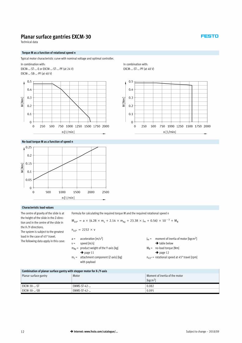
Torque M as a function of rotational speed n
Typical motor characteristic curve with nominal voltage and optimal controller.
In combination with:
EXCM-…-ST-…-E or EXCM-…-ST-…-PF (at 24 V)
EXCM-…-SB-…-PF (at 48 V)
In combination with:
EXCM-…-ST-…-PF (at 48 V)
No-load torque M as a function of speed n
Characteristic load values
The centre of gravity of the slide is at
the height of the slide in the Z-direc
tion and in the centre of the slide in
the X-/Y-directions.
The system is subject to the greatest
load in the case of 45° travel.
The following data apply in this case:
Formula for calculating the required torque M and the required rotational speed n
M45° � a � (4.28 � mL � 2.14 � mAy � 23.38 � Jm � 0.56) � 10�3 � MR
n45° � 2232 � v
a = acceleration [m/s2]
v = speed [m/s]
mAy = product weight of the Y-axis [kg]
� page 11
mL = attachment component (Z-axis) [kg]
with payload
Jm = moment of inertia of motor [kgcm2]
� table below
MR = no-load torque [Nm]
� page 12
n45° = rotational speed at 45° travel [rpm]
Combination of planar surface gantry with stepper motor for X-/Y-axis
Planar surface gantry Motor Moment of inertia of the motor
[kgcm2]
EXCM-30-…-ST EMMS-ST-42-… 0.082
EXCM-30-…-SB EMMS-ST-42-… 0.095

2018/09 – Subject to change 13� Internet: www.festo.com/catalogue/...
Planar surface gantries EXCM-30Technical data
Sample calculation
Given:
Planar surface gantry
EXCM-30-700-410-KF-ST-…-E
amax = 10 m/s2
vmax = 0.35 m/s
Payload = 2 kg
t [s]
v [m
/s]
X-/Y-axis
Z-axis
Calculation:
1. What is the max. acceleration permitted by the mechanical system?
Moving mass mL at the Y-axis:
mL = 2 kg
Stroke of the Y-axis:
410 mm
Result:
In case of a moving mass mL of 2 kg the maximum permissible acceleration is 13 m/s2.
The required acceleration of 10 m/s2 is therefore permissible.
-H- Note
The following information applies to
a horizontal mounting position. For
vertical installation positions,
please get in touch with your local
contact at Festo.
The centre of gravity of the slide is at
the height of the slide in the Z-direc
tion and in the centre of the slide in
the X-/Y-directions.
Stroke, Y-axis = 110/160/210 mm
Stroke, Y-axis = 260 mm
Stroke, Y-axis = 310 mm
Stroke, Y-axis = 360 mm
Stroke, Y-axis = 410 mm
Stroke, Y-axis = 460 mm
Stroke, Y-axis = 510 mm

Subject to change – 2018/0914 � Internet: www.festo.com/catalogue/...
Planar surface gantries EXCM-30Technical data
Sample calculation
2. Is the attached motor sufficient for this load?
a = acceleration [m/s2]
v = speed [m/s]
mAy = product weight of the Y-axis [kg]
� page 11
mL = payload
Given:
amax = 10 m/s2
vmax = 0.35 m/s
mAy = 1.32 kg
mL = 2 kg
Jm = 0.082 kgcm2
-H- Note
These requirements for the dynamic
response apply to 45° travel.
For travel only in the X- or Y-direction,
the dynamic values may be higher.
Jm = moment of inertia of motor [kgcm2]
� page 12
MR = no-load torque [Nm]
� page 12
n45° = rotational speed at 45° travel [rpm]
M45° � a � (4.28 � mL � 2.14 � mAy � 23.38 � Jm � 0.56) � 10�3 � MR
n45° � 2232 � v
n45° � 2232 � 0, 35�m�s � 781, 2�1�min
Determination of MR:
EXCM-30
MR = 0.12 Nm
M45° � 10� ms2
� (4.28 � 2�kg � 2.14 � 1.32�kg � 23.38 � 0.082�kgcm2 � 0.56) � 10�3 � 0.12�Nm � 0.26�Nm
No-load torque:
M45° � a � (4.28 � mL � 2.14 � mAy � 23.38 � Jm � 0.56) � 10�3 � MR
Result:
The value for the torque lies below the motor characteristic curve.
The design is thus acceptable.

2018/09 – Subject to change 15� Internet: www.festo.com/catalogue/...
Planar surface gantries EXCM-30Technical data
Minimum number of profile mountings
Different numbers of profile mountings must be used as a function of the
mounting position and stroke of the X-axis.
Horizontal mounting position
Stroke 500 mm Stroke 500 mm
Vertical mounting position
Stroke 500 mm Stroke 500 mm
Stroke of the X-axis Number of profile mountings
[mm] Horizontal mounting position Vertical mounting position
100 … 499 2 per profile, inside or outside 4 per profile, inside and outside
500 … 700 3 per profile, inside or outside 6 per profile, inside and outside
Stroke reduction in combination with mounting kit EAHT-E9
The reduction is influenced by the following factors:
� 1 The mounting kit EAHT-E9 is wider than the slide of the Y-axis.
� 2 Through the adjusting kit EADC-E11 or profile mounting MUE mounted on
the inside of the X-axis
� 3 Through an additional mounting surface for the cover in combination with
EXCM-…-P8 (with protection against particles)
EXCM-…
L L
1
2
L
B3
B3
L
1
3
2
EXCM-…-P8
11
3
B3 (� as of page 16) L
For EXCM-… For EXCM-…-P8 For EXCM-… For EXCM-…-P8
With mounting kit EAHT-E9
38 + stroke 63 + stroke
2x 8 mm No stroke reduction
With mounting kit EAHT-E9 and adjust
ing kits EADC-E11/profile mounting
MUE
2x 16 mm 2x 4 mm

Subject to change – 2018/0916 � Internet: www.festo.com/catalogue/...
Planar surface gantries EXCM-30Technical data
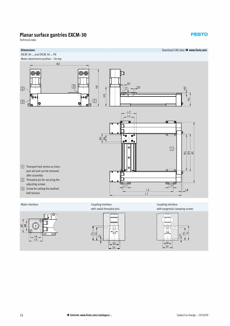
Dimensions Download CAD data � www.festo.com
EXCM-30-… and EXCM-30-…-P8
Motor attachment position – Underneath
1 Transport lock serves as trans
port aid and can be removed
after assembly
2 Threaded pin for securing the
adjusting screws
3 Screw for setting the toothed
belt tension
Motor interface Coupling interface Coupling interface
with radial threaded pins with tangential clamping screws
2018/09 – Subject to change 17� Internet: www.festo.com/catalogue/...
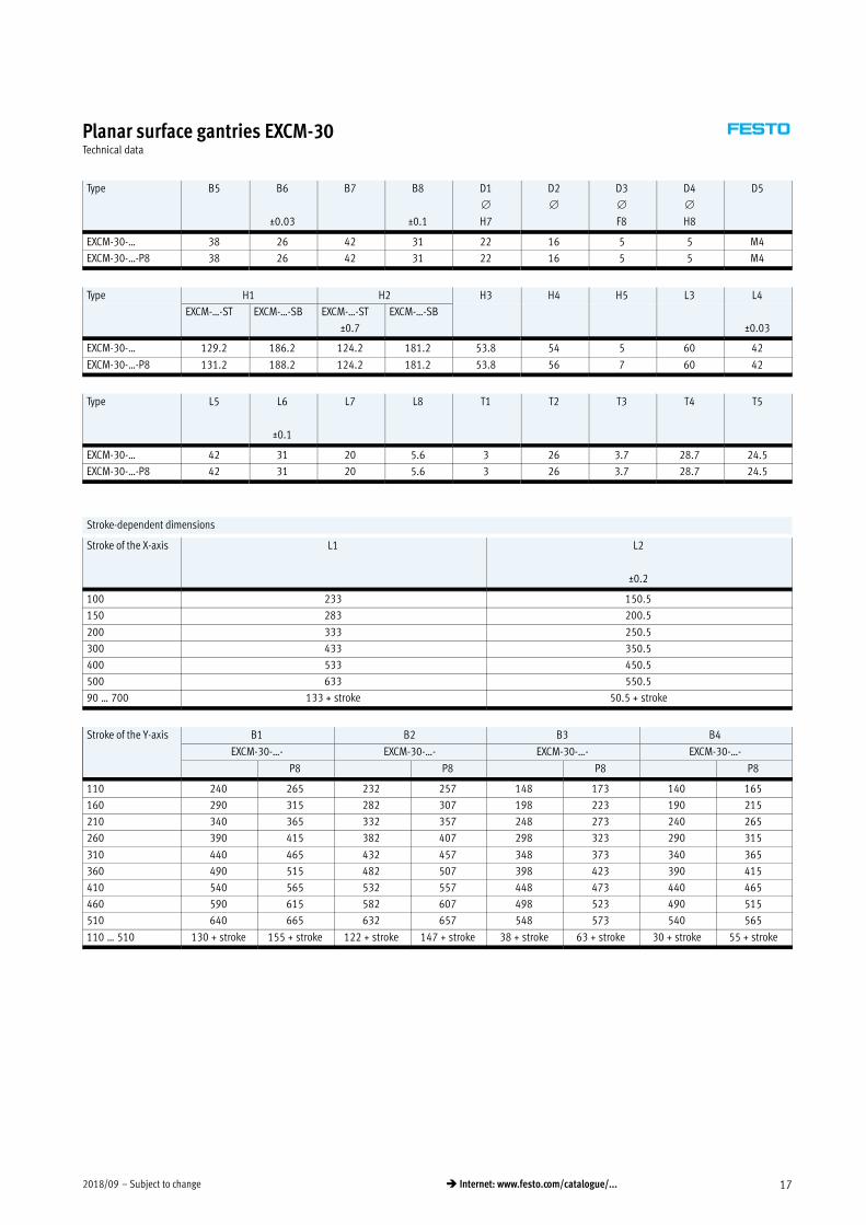
Planar surface gantries EXCM-30Technical data
Type B5 B6
±0.03
B7 B8
±0.1
D1
H7
D2
D3
F8
D4
H8
D5
EXCM-30-… 38 26 42 31 22 16 5 5 M4
EXCM-30-…-P8 38 26 42 31 22 16 5 5 M4
Type H1 H2 H3 H4 H5 L3 L4
EXCM-…-ST EXCM-…-SB EXCM-…-ST
±0.7
EXCM-…-SB
±0.03
EXCM-30-… 129.2 186.2 124.2 181.2 53.8 54 5 60 42
EXCM-30-…-P8 131.2 188.2 124.2 181.2 53.8 56 7 60 42
Type L5 L6
±0.1
L7 L8 T1 T2 T3 T4 T5
EXCM-30-… 42 31 20 5.6 3 26 3.7 28.7 24.5
EXCM-30-…-P8 42 31 20 5.6 3 26 3.7 28.7 24.5
Stroke-dependent dimensions
Stroke of the X-axis L1 L2
±0.2
100 233 150.5
150 283 200.5
200 333 250.5
300 433 350.5
400 533 450.5
500 633 550.5
90 … 700 133 + stroke 50.5 + stroke
Stroke of the Y-axis B1 B2 B3 B4
EXCM-30-…- EXCM-30-…- EXCM-30-…- EXCM-30-…-
P8 P8 P8 P8
110 240 265 232 257 148 173 140 165
160 290 315 282 307 198 223 190 215
210 340 365 332 357 248 273 240 265
260 390 415 382 407 298 323 290 315
310 440 465 432 457 348 373 340 365
360 490 515 482 507 398 423 390 415
410 540 565 532 557 448 473 440 465
460 590 615 582 607 498 523 490 515
510 640 665 632 657 548 573 540 565
110 … 510 130 + stroke 155 + stroke 122 + stroke 147 + stroke 38 + stroke 63 + stroke 30 + stroke 55 + stroke
Subject to change – 2018/0918 � Internet: www.festo.com/catalogue/...
Planar surface gantries EXCM-30Technical data
Dimensions Download CAD data � www.festo.com
EXCM-30-… and EXCM-30-…-P8
Motor attachment position – On top
1 Transport lock serves as trans
port aid and can be removed
after assembly
2 Threaded pin for securing the
adjusting screws
3 Screw for setting the toothed
belt tension
Motor interface Coupling interface Coupling interface
with radial threaded pins with tangential clamping screws

2018/09 – Subject to change 19� Internet: www.festo.com/catalogue/...
Planar surface gantries EXCM-30Technical data
Type B5 B6
±0.03
B7 B8
±0.1
D1
H7
D2
D3
F8
D4
H8
EXCM-30-… 38 26 42 31 22 16 5 5
EXCM-30-…-P8 38 26 42 31 22 16 5 5
Type D5 H2 H3 H4 H5 L3 L4
EXCM-…-ST
±1
EXCM-…-SB
±0.03
EXCM-30-… M4 146.2 203.2 75.6 54 5 60 42
EXCM-30-…-P8 M4 146.2 203.2 75.6 56 7 60 42
Type L5 L6
±0.1
L7 L8 T1 T2 T3 T4 T5
EXCM-30-… 42 31 20 5.6 3 26 3.7 28.7 24.5
EXCM-30-…-P8 42 31 20 5.6 3 26 3.7 28.7 24.5
Stroke-dependent dimensions
Stroke of the X-axis L1 L2
±0.2
100 233 150.5
150 283 200.5
200 333 250.5
300 433 350.5
400 533 450.5
500 633 550.5
90 … 700 133 + stroke 50.5 + stroke
Stroke of the Y-axis B1 B2 B3 B4
EXCM-30-…- EXCM-30-…- EXCM-30-…- EXCM-30-…-
P8 P8 P8 P8
110 240 265 232 257 148 173 140 165
160 290 315 282 307 198 223 190 215
210 340 365 332 357 248 273 240 265
260 390 415 382 407 298 323 290 315
310 440 465 432 457 348 373 340 365
360 490 515 482 507 398 423 390 415
410 540 565 532 557 448 473 440 465
460 590 615 582 607 498 523 490 515
510 640 665 632 657 548 573 540 565
110 … 510 130 + stroke 155 + stroke 122 + stroke 147 + stroke 38 + stroke 63 + stroke 30 + stroke 55 + stroke

Subject to change – 2018/0920 � Internet: www.festo.com/catalogue/...
Planar surface gantries EXCM-30Ordering data – Modular product system
Ordering table
Size 30 Condi
tions
Code Entry
code
0M Module no. 2226101
Product type EXCM series M EXCM EXCM
Size 30 -30 30
Stroke of the X-axis [mm] 100 -100
[mm] 150 -150
[mm] 200 -200
[mm] 300 -300
[mm] 400 -400
[mm] 500 -500
[mm] 90 … 700 -…
Stroke of the Y-axis [mm] 110 -110
[mm] 160 -160
[mm] 210 -210
[mm] 260 -260
[mm] 310 -310
[mm] 360 -360
[mm] 410 -410
[mm] 460 -460
[mm] 510 -510
[mm] 110 … 510 -…
Guide Recirculating ball bearing guide -KF KF
Motor type Stepper motors -ST
Stepper motors with brake -SB
Without stepper motors 1 -W
Protection against particles Standard
Protected version -P8
Motor attachment position Underneath 2 -B
Underneath, cable outlets to the front -B1
Underneath, cable outlets to the rear -B2
Underneath, cable outlets inwards -B3
Underneath, cable outlets outside -B4
Top 2 -T
On top, cable outlets to the front -T1
On top, cable outlets to the rear -T2
On top, cable outlets inwards -T3
On top, cable outlets outside -T4
1 W In combination with "Without stepper motors" W, controllers E and PF are not required
2 B, T Not in combination with stepper motors ST and SB. Option if third-party motors are mounted
Transfer order code
EXCM – 30 – – – KF – – –
Mandatory data
Options
M
O

2018/09 – Subject to change 21� Internet: www.festo.com/catalogue/...
Planar surface gantries EXCM-30Ordering data – Modular product system
Ordering table
Size 30 Condi
tions
Code Entry
code
0O Controller Without
Remote, NPN (24 V) -E
Remote, PNP (24/48 V) -PF
Cable length Without
Motor and encoder cable 0.5 m 2
Motor and encoder cable 1 m 3
Motor and encoder cable 1.5 m 4
Motor and encoder cable 2 m 5
0M Document language German -DE
English -EN
Spanish -ES
French -FR
Italian -IT
Russian -RU
Chinese -ZH
Transfer order code
– – –
Mandatory data
Options
M
O

Subject to change – 2018/0922 � Internet: www.festo.com/catalogue/...
Planar surface gantries EXCM-40Type codes
EXCM – 40 – 600 – 400 – KF – SB – B – PF 7
Type
EXCM Planar surface gantry
Size
Stroke of the X-axis [mm]
Stroke of the Y-axis [mm]
Guide
KF Recirculating ball bearing guide
Motor type
SB Stepper motor with brake
ST Stepper motor
W Without motor
Motor attachment position
B Underneath
T Top
Controller
– Without
PF Remote, PNP (48 V)
Cable length
– Without
6 5 m
7 10 m

2018/09 – Subject to change 23� Internet: www.festo.com/catalogue/...
Planar surface gantries EXCM-40Type codes
– P1 – J –
Attachment components
– Without
HE1 Electric lifting unit, 100 mm stroke
P1 Pneumatic lifting unit, 50 mm stroke
P2 Pneumatic lifting unit, 100 mm stroke
P3 Pneumatic lifting unit, 150 mm stroke
Mounting kit
– With mounting component
J With adjusting kit
Document language
DE German
EN English
ES Spanish
FR French
IT Italian
RU Russian
ZH Chinese
-H- Note
Ordering data � page 40

Subject to change – 2018/0924 � Internet: www.festo.com/catalogue/...
Planar surface gantries EXCM-40Key features
Selection of attachment components
The following variants for the Z-axis
can optionally be ordered using the
modular product system � page 40:
� Without attachment component
� With pneumatic attachment
component (mini slide DGSL)
� With electric attachment
component (mini slide EGSL)
The drives are fully connected on
delivery. Cables and tubes are routed
as far as the output of the energy
chain (X-axis).
EXCM-… (without attachment component)
The following are pre-installed:
� 2 supply ports for e.g. Z-axis � Multi-pin plug distributor for
bundling signals:
– E.g. proximity sensor
Components Number of components
1 Tubing 2
3 Bulkhead fitting 2
6 Plug socket with cable 1
7 Multi-pin plug distributor (6-way) 1
– Earthing cable 2
EXCM- … -P… (pneumatic attachment component)
The following are pre-installed:
� Solenoid valve for controlling the
drive
� 1 supply port for e.g. gripper
� Proximity sensor for end position
sensing
� Multi-pin plug distributor for
bundling signals:
– For mini slide DGSL:
– 2 proximity sensors
– 1 solenoid valve
– 3 ports are available
Components Number of components
1 Tubing 2
2 Solenoid valve 1
3 Bulkhead fitting 1
4 Mini slide DGSL-…-Y3A1 1
5 Adapter plate 1
6 Plug socket with cable 1
7 Multi-pin plug distributor (6-way) 1
8 Proximity sensor 2
– Earthing cable 2
1) For EXCM-40, the mini slide DGSL-16 is used with progressive shock absorbers.
Further information � Internet: dgsl
1
36
7
1
2
3
5
4
6
7
8
2018/09 – Subject to change 25� Internet: www.festo.com/catalogue/...
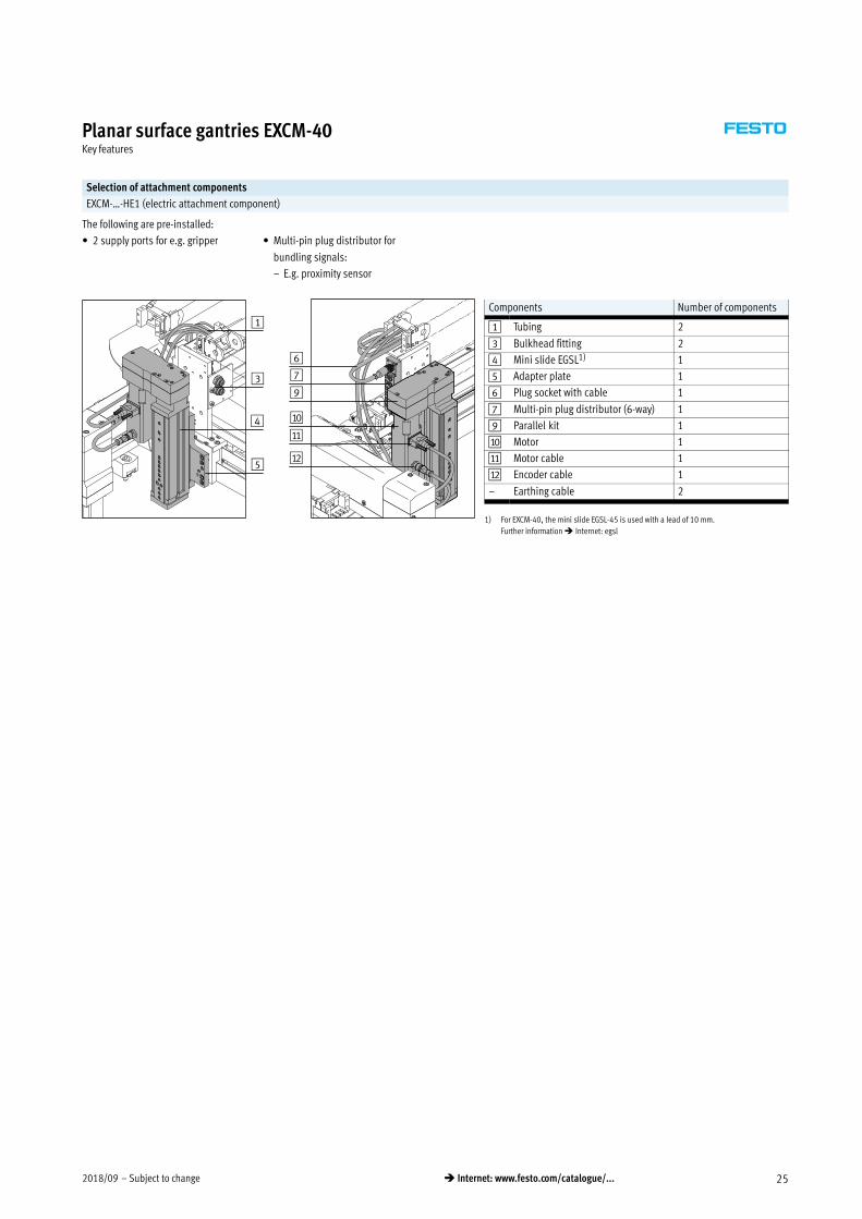
Planar surface gantries EXCM-40Key features
Selection of attachment components
EXCM-…-HE1 (electric attachment component)
The following are pre-installed:
� 2 supply ports for e.g. gripper � Multi-pin plug distributor for
bundling signals:
– E.g. proximity sensor
Components Number of components
1 Tubing 2
3 Bulkhead fitting 2
4 Mini slide EGSL1) 1
5 Adapter plate 1
6 Plug socket with cable 1
7 Multi-pin plug distributor (6-way) 1
9 Parallel kit 1
aJ Motor 1
aA Motor cable 1
aB Encoder cable 1
– Earthing cable 2
1) For EXCM-40, the mini slide EGSL-45 is used with a lead of 10 mm.
Further information � Internet: egsl
1
3
5
4
6
7
9
aJ
aA
aB
Subject to change – 2018/0926 � Internet: www.festo.com/catalogue/...
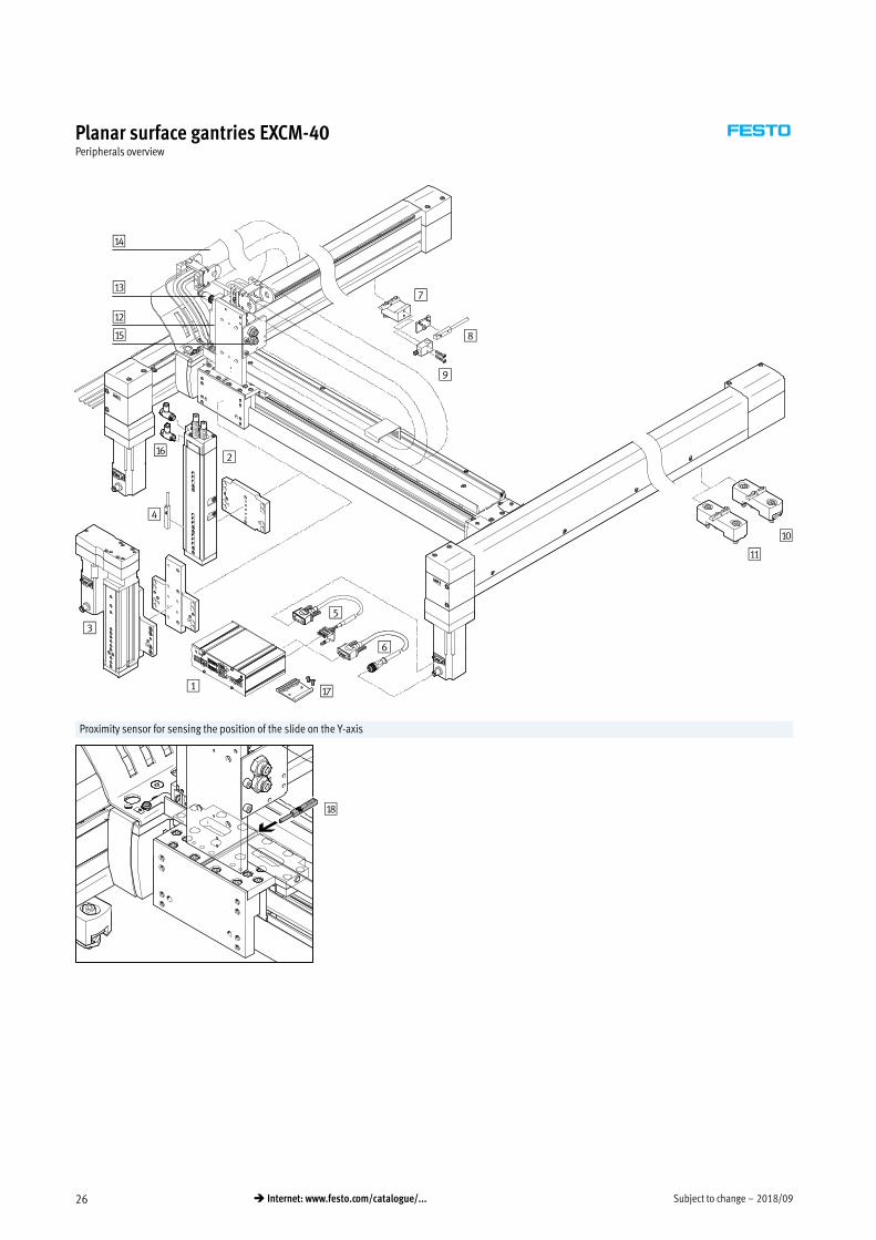
Planar surface gantries EXCM-40Peripherals overview
2
3
1
5
6
7
9
8
4
aA
aJ
aB
aC
aD
aE
aF
aG
Proximity sensor for sensing the position of the slide on the Y-axis
aH

2018/09 – Subject to change 27� Internet: www.festo.com/catalogue/...
Planar surface gantries EXCM-40Peripherals overview
Attachments and accessories
Type Description � Page/Internet
1 Controller
CMXH
� For controlling the planar surface gantry cmxh
2 Mini slides
P1, P2, P3
� Pneumatic attachment component (mini slide DGSL) for the Z-axis 40
3 Mini slides
HE1
� Electric attachment component (mini slide EGSL) with motor cable NEBM and encoder cable
NEBM for the Z-axis
40
4 Proximity sensor
SME-10M/SIES-8M
� For position sensing on the Z-axis
� Included in the scope of delivery of the planar surface gantry EXCM-…-P…
50
5 Motor cable
NEBM
� Connecting cable between motor and controller CMXH-ST2
� Included in the scope of delivery of the planar surface gantry EXCM-…-ST/-SB
40
6 Encoder cable
NEBM
� Connecting cable between encoder and controller CMXH-ST2
� Included in the scope of delivery of the planar surface gantry EXCM-…-ST/-SB
40
7 Sensor mounting
EAPR
� For mounting the proximity sensors SIES-Q8B, SIES-V3B on the X-axis
� Not included in the scope of delivery of the planar surface gantry
49
8 Proximity sensor
SIES-Q8B
� For position sensing on the X-axis
� Not included in the scope of delivery of the planar surface gantry
51
9 Proximity sensor
SIES-V3B
� For position sensing on the X-axis
� Not included in the scope of delivery of the planar surface gantry
51
aJ Adjusting kit
EADC-12
� Height-adjustable mounting kit for the planar surface gantry
� Included in the scope of delivery of the planar surface gantry. If no adjusting kit is selected in
the modular product system, the mounting kit will automatically be delivered
48
aA Mounting kit
EAHM-E12
� Non-height-adjustable mounting kit for the planar surface gantry 48
aB Multi-pin plug distributor
NEDU
� For connecting up to 6 inputs/outputs
� Included in the scope of delivery of the planar surface gantry
nedu
aC Plug socket with cable
SIM
� Connecting cable between multi-pin plug distributor NEDU and the controller
� Included in the scope of delivery of the planar surface gantry
sim
aD Energy chain � For EXCM-40: type IGUS 2500.03.075.0 –
aE Plastic tubing
PUN-H-6x1
� Two pieces of tubing are connected to the bulkhead fittings and routed in the energy chains at
delivery (for pneumatic Z-axis, one tube on the valve and one on the bulkhead fitting)
pun
aF One-way flow control valve
GRLA
� For speed regulation
� Included in the scope of delivery of the planar surface gantry EXCH-…-P…
40
aG H-rail mounting
CAFM-D3
For mounting the controller to an H-rail to EN 50022 43
aH Proximity sensor
SIES-8M
� For position sensing on the Y-axis
� Not included in the scope of delivery of the planar surface gantry
50
– Motor cable
NEBM-S1G9
� Connecting cable between the motor on the Z-axis and the motor controller CMMS-ST
� The motor controller and connecting cable are included in the scope of delivery of the planar
surface gantry EXCM-…-HE1
51
Encoder cable
NEBM-M12G8
� Connecting cable between the encoder on the Z-axis and the motor controller CMMS-ST
� The motor controller and connecting cable are included in the scope of delivery of the planar
surface gantry EXCM-…-HE1
51

Subject to change – 2018/0928 � Internet: www.festo.com/catalogue/...
Planar surface gantries EXCM-40Technical data
General technical data
Design Planar surface gantry
Guide Recirculating ball bearing guide
Stroke of the
X-axis [mm] 200 … 2000
Y-axis [mm] 200 … 1000
Z-axis [mm] 50, 100, 150
EXCM-…-HE1 [mm] 100
EXCM-…-P1 [mm] 50
EXCM-…-P2 [mm] 100
EXCM-…-P3 [mm] 150
Rated load for max. dynamic response1) [kg] 4
Process force in Z direction [N] 450
Max. torque2) � page 31
Max. no-load torque2)3) � page 31
Max. acceleration4)
With motor and controller [m/s2] � page 31
Purely mechanical system [m/s2] 20
Max. speed4)
With motor and controller [m/s] 1
Purely mechanical system [m/s] 2
Repetition accuracy [mm] ±0.1
Mounting position Horizontal
Type of mounting Mounting kit, adjusting kit
1) Rated load = tool load (attachment component (Z-axis) + gripper, for example) + payload
2) These values must also be complied with during installation of third-party motors
3) At v=0.2 m/s and 45° travel.
4) These data apply only under ideal conditions.
For a precise configuration, please consult a sales engineer from Festo.
Further information � page 31
Operating and environmental conditions
Degree of protection IP40
Ambient temperature1) [°C] +10 … +50
Storage temperature [°C] –10 … +60
Relative humidity [%] 0 … 90 (non-condensing)
Noise level [dB(A)] 65
Duty cycle [%] 100
CE marking (see declaration of conformity) To EC Machinery Directive
1) Note operating range of proximity sensors and motors

2018/09 – Subject to change 29� Internet: www.festo.com/catalogue/...
Planar surface gantries EXCM-40Technical data
Materials
1
4
5
4
3
2
Size 40
1 Drive and end caps Aluminium
2 Profiles of the X-axis Aluminium
3 Profile of the Y-axis Aluminium
4 Cover
X-axis Aluminium
Y-axis Aluminium
5 Slides Aluminium
– Coupling Aluminium with elastomer ring gear
Guide Steel
Drive pinion Steel
Ball bearings Steel
Toothed belt PU with steel cord
Note on materials RoHS compliant
Contains paint-wetting impairment substances

Subject to change – 2018/0930 � Internet: www.festo.com/catalogue/...
Planar surface gantries EXCM-40Technical data
Weight [kg]
Product weight with 0 mm stroke (without rated load, motors, axial kits, mounting kits)
EXCM-…-W-T 16.7
EXCM-…-W-B 17.5
X-axis (2x) 8.5
Y-axis (without slide) 6.2
Additional weight per 100 mm stroke
X-axis 1.75
Y-axis 0.89
Axial kit1)
For EMMS-ST-57-M 0.54
Motor1)
EXCM-…-ST (without brake) 1.2
EXCM-…-SB (with brake) 1.38
Attachment component (Z-axis)
Electrical
EXCM-…-HE1 3.3
Pneumatic
EXCM-…-P1 1.8
EXCM-…-P2 2.4
EXCM-…-P3 2.7
Mounting kit for X-axis
Adjusting kit1) 0.78
Mounting kit1) 0.33
1) Weight per component

2018/09 – Subject to change 31� Internet: www.festo.com/catalogue/...
Planar surface gantries EXCM-40Technical data
Torque M as a function of rotational speed n No-load torque M as a function of speed n
Typical motor characteristic curve with nominal voltage and optimal controller.
In conjunction with:
EXCM-…-ST-…-PF (at 48 V) or EXCM-…-SB-…-PF (at 48 V)
Characteristic load values
The centre of gravity of the slide is at
the height of the slide in the Z-direc
tion and in the centre of the slide in
the X-/Y-directions.
The system is subject to the greatest
load in the case of 45° travel.
The following data apply in this case:
Formula for calculating the required torque M and the required rotational speed n
M45° � a � (9.79 � mL � 4.89 � mAy � 10.21 � Jm � 19.58) � 10�3 � MR
n45° � 975 � v
a = acceleration [m/s2]
v = speed [m/s]
mAy = product weight of the Y-axis [kg]
� page 30
mL = attachment component (Z-axis) [kg]
with payload
Jm = moment of inertia of the motor [kgcm2]
� table below
MR = no-load torque [Nm]
� page 31
n45° = rotational speed at 45° travel [rpm]
Combination of planar surface gantry with servo motor for X-/Y-axis
Planar surface gantry Motor Moment of inertia of motor
[kgcm2]
EXCM-40-…-ST EMMS-ST-57-M-SE-G2 0.48
EXCM-40-…-SB EMMS-ST-57-M-SEB-G2 0.5

Subject to change – 2018/0932 � Internet: www.festo.com/catalogue/...
Planar surface gantries EXCM-40Technical data
Sample calculation
Given:
Planar surface gantry
EXCM-40-1000-500-KF-SB-B-PF7-HE1-…
with attached motor
EMMS-ST-57-M-SEB-G2
amax = 2 m/s2
vmax = 0.5 m/s
Payload = 0.5 kg
Attachment component Z-axis: EGSL-BS-45-100-10P
t [s]
v [m
/s]
X-/Y-axis
Z-axis
Is the attached motor sufficient for this load?
a = acceleration [m/s2]
� page 28
v = speed [m/s]
mAy = product weight of the Y-axis [kg]
� page 30
mL = attachment component (Z-axis) [kg]
with payload
Given:
amax = 2 m/s2
vmax = 0.5 m/s
mAy = 10.65 kg
mL = 3.80 kg
Jm = 0.5 kgcm2
-H- Note
These requirements for the dynamic
response apply to 45° travel.
For travel only in the X- or Y-direction,
the dynamic values may be higher.
Jm = moment of inertia of the motor [kgcm2]
� page 31
MR = no-load torque [Nm]
� page 31
n45° = rotational speed at 45° travel [rpm]
M45° � a � (9.79 � mL � 4.89 � mAy � 10.21 � Jm � 19.58) � 10�3 � MR
n45° � 975 � v

2018/09 – Subject to change 33� Internet: www.festo.com/catalogue/...
Planar surface gantries EXCM-40Technical data
Sample calculation
n45° � 975 � 0.5�m�s � 487.5�1�min
Determination of MR:
MR = 0.4 Nm
M45° � 2� ms2
� (9.79 � 3.80�kg � 4.89 � 10.65�kg � 10.21 � 0.5�kgcm2 � 19.58) � 10�3 � 0.4�Nm � 0.63�Nm
M45° � a � (9.79 � mL � 4.89 � mAy � 10.21 � Jm � 19.58) � 10�3 � MR
EXCM-40
No-load torque:
Result:
The value for the torque lies below the motor characteristic curve.
The design is thus acceptable.

Subject to change – 2018/0934 � Internet: www.festo.com/catalogue/...
Planar surface gantries EXCM-40Technical data
Minimum number of profile mountings
Irrespective of the mounting position,
a different number of profile mount
ings needs to be used depending on
the stroke of the X-axis.
The item is delivered with the required
number attached.
Stroke of the X-axis Number of profile mountings per axis
[mm]
200… 499 2
500… 899 2
900 … 1799 3
1800 … 2000 4
Distances between the profile mountings
The profile mountings must be evenly
spaced by distance l.
Distance�l � Stroke � 141n � 1
n = number of profile mountings per axis
Mounting position of the Z-axis
Owing to manufacturing tolerances
and the backlash in the guides, the
angle between the X- and Z-axes may
not be exactly 90° in certain
circumstances.
Max. deviation:
á = ±1.1°
á
2018/09 – Subject to change 35� Internet: www.festo.com/catalogue/...
Planar surface gantries EXCM-40Technical data
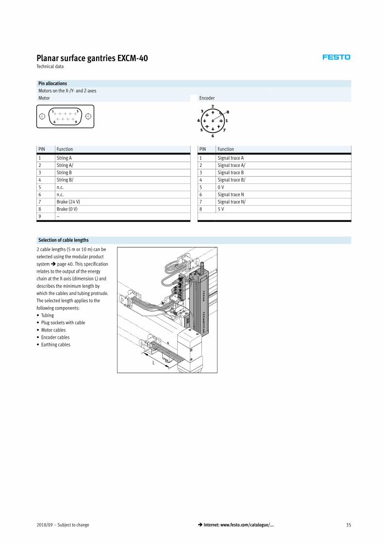
Pin allocations
Motors on the X-/Y- and Z-axes
Motor Encoder
PIN Function PIN Function
1 String A 1 Signal trace A
2 String A/ 2 Signal trace A/
3 String B 3 Signal trace B
4 String B/ 4 Signal trace B/
5 n.c. 5 0 V
6 n.c. 6 Signal trace N
7 Brake (24 V) 7 Signal trace N/
8 Brake (0 V) 8 5 V
9 –
Selection of cable lengths
2 cable lengths (5 m or 10 m) can be
selected using the modular product
system � page 40. This specification
relates to the output of the energy
chain at the X-axis (dimension L) and
describes the minimum length by
which the cables and tubing protrude.
The selected length applies to the
following components:
� Tubing
� Plug sockets with cable
� Motor cables
� Encoder cables
� Earthing cables
L

Subject to change – 2018/0936 � Internet: www.festo.com/catalogue/...
Planar surface gantries EXCM-40Technical data
Dimensions Download CAD data � www.festo.com
EXCM-40-…-T – Motor attachment position on top
1 Screw for toothed belt tension
2 Earthing point
L8 Safety distance per side
EXCM-40-…-B – Motor attachment position underneath EXCM-40-… – Motor interface

2018/09 – Subject to change 37� Internet: www.festo.com/catalogue/...
Planar surface gantries EXCM-40Technical data
Dimensions Download CAD data � www.festo.com
EXCM-40-… – Slide
Type B3 B4 B5 B6 B9 B10 B11 B12 B13
±0.05
B14
±0.1
EXCM-40 65 65 69 179.9 56.4 41 35 30 27 106
Type B15
±0.03
D1
H7
D2
H6
D3 D4
H7
D5
H7
D6 H1 H2 H3
EXCM-4085 38 12 M5 4 6 M6
Approx.
293100.8 124/159.51)
Type H4 H5 H6 H7 H8 H9 L3 L4 L5 L6 L7 L8
EXCM-40 65 33.6 20 20 100.3 0.5 101 70 70 30.5 37.5 6
Type L10 L11
±0.03
L12 L13
±0.1
L14
±0.1
L15 L16
±0.1
T1 T2 T3 T4 ß1
EXCM-40 70 46 41 44 32 18.5 12 12 6 1.9 7 6
Stroke-dependent dimensions
Stroke of the X-axis L1 L2 L18 Stroke of the Y-axis B1 B2
200 … 2000 382+stroke � page 34 167.2+stroke 200 … 1000 360+stroke 230+stroke
1) With brake
-H- Note
Depending on the stroke of the
X-axis, a varying number of profile
mountings is required. The distance
between the profile mountings must
always be the same (� page 34).
The tension of the toothed belt must
be set before commissioning. The
tools required to do this
(e.g. frequency meter) are not
included in the scope of delivery.
Subject to change – 2018/0938 � Internet: www.festo.com/catalogue/...
Planar surface gantries EXCM-40Technical data
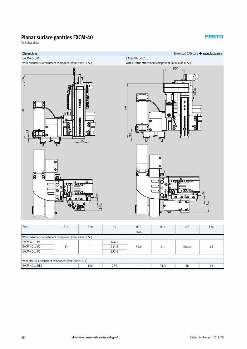
Dimensions Download CAD data � www.festo.com
EXCM-40-…-P… EXCM-40-…-HE1…
With pneumatic attachment component (mini slide DGSL) With electric attachment component (mini slide EGSL)
Type B19 B20 H9 H10
max.
H11 L23 L24
With pneumatic attachment component (mini slide DGSL)
EXCM-40-…-P1
33 –
164.6
51.9 9.1 40±0.08 12EXCM-40-…-P2 243.6
EXCM-40-…-P3 293.6
With electric attachment component (mini slide EGSL)
EXCM-40-…-HE1 – 106 275 – 31.5 56 12

2018/09 – Subject to change 39� Internet: www.festo.com/catalogue/...
Planar surface gantries EXCM-40Technical data
Allocation of planar surface gantry to servo motor for X-/Y-axis
Planar surface gantry Motor
EXCM-40-…-ST EMMS-ST-57-M-SE-G2
EXCM-40-…-SB EMMS-ST-57-M-SEB-G2
Allocation of planar surface gantry to servo motor for Z-axis
Planar surface gantry Motor
EXCM-40-…-HE1 EMMS-ST-42-S-SEB-G2
-H- Note
Third-party motors with a driving
torque that is too high can damage
the planar surface gantry. When
selecting the motors, please observe
the limits specified in the technical
data.

Subject to change – 2018/0940 � Internet: www.festo.com/catalogue/...
Planar surface gantries EXCM-40Ordering data – Modular product system
Ordering table
Size 40 Conditions Code Entry
code
0M Module no. 3741955
Product type EXCM series M EXCM EXCM
Size 40 -40 -40
Stroke of the X-axis [mm] 200 … 2000
Stroke of the Y-axis [mm] 200 … 1000
Guide Recirculating ball bearing guide -KF -KF
Motor type Stepper motor with brake -SB
Stepper motor -ST
Without motor -W
Motor attachment position Underneath -B
Top -T
0O Controller Without
Remote, PNP (48 V) -PF
Cable length Without
5 m 6
10 m 7
Attachment components None
Electric lifting unit, 100 mm stroke -HE1
Pneumatic lifting unit, 50 mm stroke -P1
Pneumatic lifting unit, 100 mm stroke -P2
Pneumatic lifting unit, 150 mm stroke -P3
Mounting kit With mounting kit
With adjusting kit -J
0M Document language German -DE
English -EN
Spanish -ES
French -FR
Italian -IT
Russian -RU
Swedish -SV
Chinese -ZH
Transfer order code
EXCM – 40 – – – KF – – – – – – –
-H- Note
In combination with key feature W
(without motor), the EXCM planar
surface gantry is provided without
a coupling housing and without
a coupling.
-H- Note
The planar surface gantry can only
be operated with the controller
CMXH and a load voltage of 48 V.
Mandatory data
Options
M
O

2018/09 – Subject to change 41� Internet: www.festo.com/catalogue/...
Planar surface gantries EXCMController – Technical data
Controller EXCM-…-E…
For sizes 30
Configuration support
via FCT plug-in EXCM
Technical data � table below
Controller EXCM-…-PF…
For sizes 30 and 40
Configuration support
via FCT plug-in CMXH
Technical data � Internet: cmxh
Technical data – Controller
Operational principle Cascade controller P position controller, PI speed controller, PI current regulator;
Current regulation inside the cascade controller
PWM MOSFET power output stage
Operating mode Direct operation
Set selection
Rotary position encoder Optical encoder, 2000 steps/rev.
Status display 7-segment display
LED
Encoder interface input RS422
Adjustable current reduction Via software
Nominal current setting Via software
Step adjustment Via software
Braking resistor [ 15
Mains filter Integrated
Electrical data – Controller
For EXCM size 30
Load supply
Nominal voltage [V DC] 24 _15%
Nominal current [A] 6
Maximum peak current [A] 8
Logic supply
Nominal voltage [V DC] 24 _15%
Maximum peak current [A] 0.3
Maximum peak current per digital output [A] 0.1
Characteristics of digital logic outputs Not galvanically isolated
Characteristics of logic inputs Galvanically connected to logic potential
Logic input specification Based on IEC 61131-2
Switching logic NPN (negative switching)
Protective function I²t monitoring, following error monitoring, software end-position detection,
voltage failure detection, current monitoring, temperature monitoring
Technical data – Fieldbus interface
Interfaces I/O CANopen Ethernet
Number of digital logic outputs 5
Number of digital logic inputs 9
Operating range of logic inputs [V DC] 8 … 30
Process interfacing 31 records
Communication profile – FHPP FHPP (via TCP/IP – CVE)
Max. fieldbus transmission rate [Mbit/s] – 1 100
Bus connection Bushing, 15-pin, Sub-D Plug connector, 9-pin, Sub-D RJ45
Subject to change – 2018/0942 � Internet: www.festo.com/catalogue/...
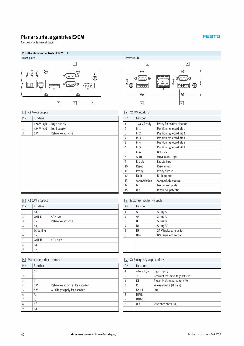
Planar surface gantries EXCMController – Technical data
Pin allocation for Controller EXCM-…-E…
Front plate Reverse side
1
3
6 2
5 5
4 4
1 X1 Power supply 2 X2 I/O interface
PIN Function PIN Function
1 +24 V logic Logic supply 1 +24 V Ready Ready for communication
2 +24 V load Load supply 2 In 1 Positioning record bit 1
3 0 V Reference potential 3 In 2 Positioning record bit 2
4 In 3 Positioning record bit 3
5 In 4 Positioning record bit 4
6 In 5 Positioning record bit 5
7 In 6 Not used
8 Start Move to the right
9 Enable Enable input
10 Reset Reset input
11 Ready Ready output
12 Fault Fault output
13 Acknowledge Acknowledge output
14 MC Motion complete
15 0 V Reference potential
3 X3 CAN interface 4 Motor connection – supply
PIN Function PIN Function
1 n.c. 1 A String A
2 CAN_L CAN low 2 A/ String A/
3 GND Reference potential 3 B String B
4 n.c. 4 B/ String B/
5 Screening 5 BR+ 24 V brake connection
6 n.c. 6 BR– 0 V brake connection
7 CAN_H CAN high
8 n.c.
9 n.c.
5 Motor connection – encoder 6 X4 Emergency stop interface
PIN Function PIN Function
1 O 1 +24 V logic Logic supply
2 B 2 TO Interrupt motor voltage (at 0 V)
3 N 3 ES Trigger braking ramp (at 0 V)
4 0 V Reference potential for encoder 4 RB Release brake (at 24 V)
5 5 V Auxiliary supply for encoder 5 FAULT Fault
6 A/ 6 DIAG1
7 B/ 7 DIAG2
8 N/ 8 0 V Reference potential
9 n.c.

2018/09 – Subject to change 43� Internet: www.festo.com/catalogue/...
Planar surface gantries EXCMController – Technical data
Dimensions for Controller EXCM-…-E… Download CAD data � www.festo.com
B1 B2 H1 H2 L1 L2
134.4 112 50 34 149 104
H-rail mounting CAFM
for H-rail to EN 50022
Materials:
Anodised aluminium
RoHS-compliant
1 Socket head screw M4x8
Dimensions and ordering data
D1 H1 H2 L1 L2 L3 Weight Part No. Type
[g]
4.2 52 22.5 50 34 8 29 4135048 CAFM-D3-H
Subject to change – 2018/0944 � Internet: www.festo.com/catalogue/...
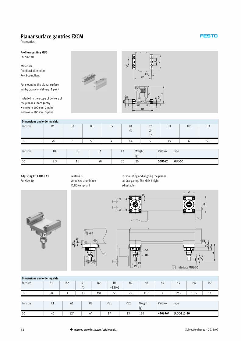
Planar surface gantries EXCMAccessories
Profile mounting MUE
For size 30
Materials:
Anodised aluminium
RoHS-compliant
For mounting the planar surface
gantry (scope of delivery: 1 pair)
Included in the scope of delivery of
the planar surface gantry:
X-stroke 500 mm: 2 pairs
X-stroke 500 mm: 3 pairs
Dimensions and ordering data
For size B1 B2 B3 B5 D1 D2 H1 H2 H3
H7
30 58 8 50 4 3.4 5 49 6 5.5
For size H4 H5 L1 L2 Weight Part No. Type
[g]
30 2.3 11 40 20 20 558042 MUE-50
Adjusting kit EADC-E11
For size 30
Materials:
Anodised aluminium
RoHS compliant
For mounting and aligning the planar
surface gantry. The kit is height
adjustable.
1 Interface MUE-50
Dimensions and ordering data
For size B1 B2 D1 D2 H1 H2 H3 H4 H5 H6 H7
+12/–2
30 58 3 33 M8 58 22 11.5 4 19.5 13.5 11
For size L1 W1 W2 ß1 ß2 Weight Part No. Type
[g]
30 40 12° 6° 17 13 160 4706964 EADC-E11-30

2018/09 – Subject to change 45� Internet: www.festo.com/catalogue/...
Planar surface gantries EXCMAccessories
Mounting kit EAHT-E9
For size 30
Materials:
Anodised aluminium
RoHS-compliant
Prepared hole pattern for:
� Mini slides EGSL-35
� Mini slides DGSL-8/-10/-12
� Electric slide EGSK-20/-26
� Electric cylinders EPCO-16
� Mini slides EGSC-BS-25/-32
Dimensions and ordering data
For size B1 B2 B3 B4 B5 B6 B7 B8 B9 B10 D1 D2
H7
30 50 40 36 25 24 42 35 20 18 26 5 4.5
For size D3 D4 D5 D6 D7 D8 D9 D10 D11 D12 D13 D14
H7
H7
H7
30 M4 M5 M4 M4 7 M5 7 M4 7 4.5 4.5 M4
For size D15 D16 D17 H1 H2 H3 H4 H5 H6 H7 H8 H9
±0.2
30 M3 M4 M4 125 85 40 118 90 80 15 50 30
For size H10 H11 H12 H13 H14 H15 H16 H17 H18 H19 L1 L2
30 40 20 20 55 60 9 40 20.5 40 10.5 65 42
For size L3 L4 L5 L6 T1 T2 Weight Part No. Type
±0.1 ±0.1
[g]
30 15 20 6 5 1.6 1.6 165 4070088 EAHT-E9-FB-3D-30

Subject to change – 2018/0946 � Internet: www.festo.com/catalogue/...
Planar surface gantries EXCMAccessories
Sensor mounting EAPR
For size 30
(incl. switch lug)
Materials:
Holder: Wrought aluminium alloy
Switch lug: Steel
RoHS compliant
-H- Note
For homing in combination with
third-party motors.
Dimensions and ordering data
For size B1 B2 B3 B4 B5 B6 D1 D2 D3 H1
30 51.5 5 39 23 8.4 5.3 6.5 3.4 2.6 40
For size H2 H3 H4 H5 H6 H7 L1 L2 L3 L4
30 28 23 13 8 6 3 30 22 8 15
For size L5 L6 L7 L8 T1 Weight Part No. Type
[g]
30 4.5 6.5 3 2.5 2 330 2319236 EAPR-E11-30
2018/09 – Subject to change 47� Internet: www.festo.com/catalogue/...
Planar surface gantries EXCMAccessories
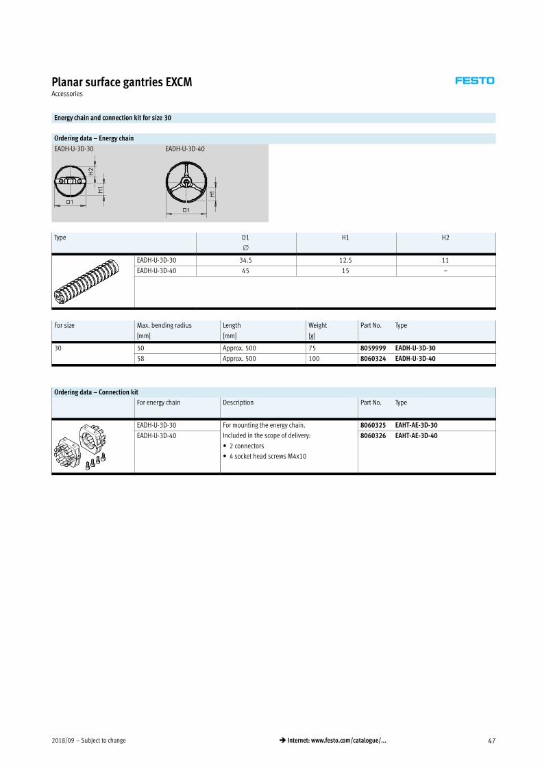
Energy chain and connection kit for size 30
Ordering data – Energy chain
EADH-U-3D-30 EADH-U-3D-40
Type D1 H1 H2
EADH-U-3D-30 34.5 12.5 11
EADH-U-3D-40 45 15 –
For size Max. bending radius Length Weight Part No. Type
[mm] [mm] [g]
30 50 Approx. 500 75 8059999 EADH-U-3D-30
58 Approx. 500 100 8060324 EADH-U-3D-40
Ordering data – Connection kit
For energy chain Description Part No. Type
EADH-U-3D-30 For mounting the energy chain.
Included in the scope of delivery:
� 2 connectors
� 4 socket head screws M4x10
8060325 EAHT-AE-3D-30
EADH-U-3D-40 8060326 EAHT-AE-3D-40

Subject to change – 2018/0948 � Internet: www.festo.com/catalogue/...
Planar surface gantries EXCMAccessories
Adjusting kit EADC-E12
For size 40
Materials:
Anodised aluminium
RoHS compliant
For mounting and aligning the planar
surface gantry. The kit is height
adjustable.
1 Adjustable
2 Width of oblong hole
Height differences of up to 5 mm
can be compensated using the
adjusting kit.
Dimensions and ordering data
For size B1 B2 B3 B4 B5 D1 H1 H2
±0.2
40 110 78 26 36.5 5 M8 29 129.8
For size H3 H4 L1 T1 Weight Part No. Type
Min. max. max. ±0.1 [g]
40 34.8 39.8 14 37 10 800 8029165 EADC-E12-40
Mounting kit EAHM-E12
For size 40
Materials:
Anodised aluminium
RoHS compliant
For mounting of the planar surface
gantry. The kit is not height
adjustable.
2 Width of oblong hole
No compensation is possible us
ing the mounting kit.
Dimensions and ordering data
For size B1 B2 B3 B4 B5 D1 H1
±0.2 ±0.2
40 110 78 26 36.5 5 M8 30
For size H2 H4 L1 T1 Weight Part No. Type
max. ±0.1 [g]
40 131.3 14 37 10 330 3489340 EAHM-E12-K-40

2018/09 – Subject to change 49� Internet: www.festo.com/catalogue/...
Planar surface gantries EXCMAccessories
Sensor mounting EAPR
For size 40
Materials:
Switch lug: Steel
Sensor bracket: Wrought aluminium
alloy
RoHS-compliant
For proximity sensor
SIES-V3B and SIES-Q8B
(for sensing the slide position on the
X-axis)
Dimensions and ordering data
For size B1 B2 B3 H1 H2 H3 H4 H5 H6 H7
±0.1 –0.1 –0.2
40 44 36.3 4 21.8 21 15 2.5 6.1 3.1 3
For size L1 L2 L3 L4 Weight Part No. Type
[g]
40 36 20 35 25 120 2536353 EAPR-E12-40

Subject to change – 2018/0950 � Internet: www.festo.com/catalogue/...
Planar surface gantries EXCMAccessories
Proximity sensors for size 30
Ordering data – Proximity sensor for T-slot, inductive Technical data � Internet: sies
Type of mounting Electrical connection Switching
output
Cable length Part No. Type
[m]
N/O contact
Insertable in the slot from above,
flush with the cylinder profile
Cable, 3-wire PNP 7.5 551386 SIES-8M-PS-24V-K-7,5-OE
Plug connector M8x1,
3-pin
0.3 551387 SIES-8M-PS-24V-K-0,3-M8D
Cable, 3-wire NPN 7.5 551396 SIES-8M-NS-24V-K-7,5-OE
Plug connector M8x1,
3-pin
0.3 551397 SIES-8M-NS-24V-K-0,3-M8D
N/C contact
Insertable in the slot from above,
flush with the cylinder profile
Cable, 3-wire PNP 7.5 551391 SIES-8M-PO-24V-K-7,5-OE
Plug connector M8x1,
3-pin
0.3 551392 SIES-8M-PO-24V-K-0,3-M8D
Cable, 3-wire NPN 7.5 551401 SIES-8M-NO-24V-K-7,5-OE
Plug connector M8x1,
3-pin
0.3 551402 SIES-8M-NO-24V-K-0,3-M8D
-H- Note
For homing in combination with
third-party motors.
Proximity sensors for size 40
Permissible proximity sensor for sensing the position of the slide on the Y-axis
Ordering data – Proximity sensors for T-slot, inductive Technical data � Internet: sies
Type of mounting Electrical connection Switching
output
Cable length Part No. Type
[m]
Inserted in the slot from above, flush
with the cylinder profile
Plug connector M8x1,
3-pin
PNP, N/O
contact
0.3 551387 SIES-8M-PS-24V-K-0,3-M8D
Permissible proximity sensors for sensing the positions on the Z-axis
Ordering data – Proximity sensors for T-slot Technical data � Internet: smt
Type of mounting Electrical connection Switching
output
Cable length Part No. Type
[m]
With mini slide DGSL (magneto-resistive)
Inserted in the slot from above, flush
with the cylinder profile
Plug connector M8x1,
3-pin
PNP, N/O
contact
0.3 551367 SME-10M-DS-24V-E-0,3-L-M8D
With mini slide EGSL (inductive)
Inserted in the slot from above, flush
with the cylinder profile
Plug connector M8x1,
3-pin
PNP, N/O
contact
0.3 551387 SIES-8M-PS-24V-K-0,3-M8D

2018/09 – Subject to change 51� Internet: www.festo.com/catalogue/...
Planar surface gantries EXCMAccessories
Permissible proximity sensors in combination with sensor mounting EAPR-E12
Ordering data – Proximity sensors Technical data � Internet: sies
Type of mounting Electrical connection Switching
output
Part No. Type
N/O contact
Screwed on Plug connector M8x1, 3-pin PNP 150491 SIES-V3B-PS-S-L
N/C contact
Screwed on Cable, 3-wire NPN 174550 SIES-Q8B-NO-K-L
Ordering data
Description Cable length
[m]
Part No. Type
Control cable NEBC
For the I/O interface to any controller 1 2307459 NEBC-S1H15-E-1.0-N-LE15
2.5 2052917 NEBC-S1H15-E-2.5-N-LE15
5 2052918 NEBC-S1H15-E-5.0-N-LE15
10 2052919 NEBC-S1H15-E-10.0-N-LE15
Cables for Z-axis for size 40
Ordering data
Description Cable length
[m]
Part No. Type
Motor cable NEBM
– Min. bending radius: 62 mm
– Suitable for use with energy chains
– Ambient temp.:
–40 … +80 °C
10 1450372 NEBM-S1G9-E-10-Q5-LE6
Encoder cable NEBM
– Min. bending radius: 51 mm
– Suitable for use with energy chains
– Ambient temp.:
–40 … +70 °C
10 550749 NEBM-M12G8-E-10-S1G9
15 550750 NEBM-M12G8-E-15-S1G9