planar inverted f antennas in free space and cell phone · planar inverted f antennas in free space...
TRANSCRIPT
Planar Inverted F Antennas in Free Space and Cell Phone
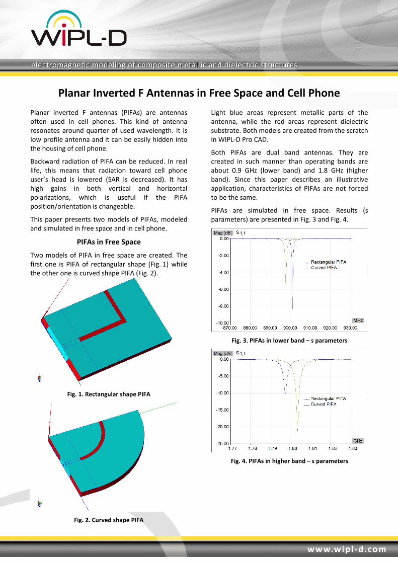
Planar inverted F antennas (PIFAs) are antennas
often used in cell phones. This kind of antenna
resonates around quarter of used wavelength. It is
low profile antenna and it can be easily hidden into
the housing of cell phone.
Backward radiation of PIFA can be reduced. In real
life, this means that radiation toward cell phone
user’s head is lowered (SAR is decreased). It has
high gains in both vertical and horizontal
polarizations, which is useful if the PIFA
position/orientation is changeable.
This paper presents two models of PIFAs, modeled
and simulated in free space and in cell phone.
PIFAs in Free Space
Two models of PIFA in free space are created. The
first one is PIFA of rectangular shape (Fig. 1) while
the other one is curved shape PIFA (Fig. 2).
Fig. 1. Rectangular shape PIFA
Fig. 2. Curved shape PIFA
Light blue areas represent metallic parts of the
antenna, while the red areas represent dielectric
substrate. Both models are created from the scratch
in WIPL-D Pro CAD.
Both PIFAs are dual band antennas. They are
created in such manner than operating bands are
about 0.9 GHz (lower band) and 1.8 GHz (higher
band). Since this paper describes an illustrative
application, characteristics of PIFAs are not forced
to be the same.
PIFAs are simulated in free space. Results (s
parameters) are presented in Fig. 3 and Fig. 4.
Fig. 3. PIFAs in lower band – s parameters
Fig. 4. PIFAs in higher band – s parameters

PIFAs in Cell Phone
Model of cell phone is obtained by converting
WIPL-D Pro CAD phone model to WIPL-D Pro
(Fig. 5).
Fig. 5. Cell phone in WIPL-D Pro
PIFAs are converted from WIPL-D Pro CAD to
WIPL-D Pro and imported in the cell phone WIPL-D
Pro model (Fig. 6 and Fig. 7).
Ground plane and electronic devices inside phone
are modeled using metallic shape shown in Fig. 6
and Fig. 7. PIFAs’ dielectric substrate is shown here
using orange color.
Fig. 6. Rectangular PIFA in cell phone with ground plane
and modeled electronic devices inside the phone
Fig. 7. Curved PIFA in cell phone with ground plane and
modeled electronic devices inside the phone
PIFAs are simulated in cell phone. Results (s
parameters) are presented and compared with
results from PIFAs in free space (Fig. 8 and Fig. 9).
Fig. 8. PIFAs in free space and cell phone. Lower band –
s parameters
Fig. 9. PIFAs in free space and cell phone. Higher band –
s parameters

Radiation Pattern Comparisons
Minimum values of s11 parameter are found for
curved and rectangular PIFA, in both lower and
higher frequency band. In lower frequency band,
rectangular PIFA in cell phone resonates at
910.52 MHz while curved PIFA in cell phone
resonates at 896.74 MHz. In higher frequency band,
rectangular PIFA in cell phone resonates at
1.79772 GHz while curved PIFA in cell phone
resonates at 1.79867 GHz (shown with less decimal
digits on markers in Fig. 9).
Radiation patterns for circular and rectangular
PIFAs, in free space and in cell phone are presented
(Figs. 10-17). Operating frequencies are frequencies
where s11 of PIFAs in cell phone models reach for
minimal value.
Fig. 10. Rectangular PIFA in free space – radiation
pattern at 910.52 MHz
Fig. 11. Rectangular PIFA in free space – radiation
pattern at 1.79772 GHz
Fig. 12. Circular PIFA in free space – radiation pattern at
896.74 MHz
Fig. 13. Circular PIFA in free space – radiation pattern at
1.79868 GHz
Fig. 14. Rectangular PIFA in cell phone – radiation
pattern at 910.52 MHz
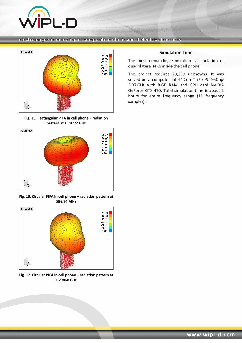
Fig. 15. Rectangular PIFA in cell phone – radiation
pattern at 1.79772 GHz
Fig. 16. Circular PIFA in cell phone – radiation pattern at
896.74 MHz
Fig. 17. Circular PIFA in cell phone – radiation pattern at
1.79868 GHz
Simulation Time
The most demanding simulation is simulation of
quadrilateral PIFA inside the cell phone.
The project requires 29,299 unknowns. It was
solved on a computer Intel® Core™ i7 CPU 950 @
3.07 GHz with 8 GB RAM and GPU card NVIDIA
GeForce GTX 470. Total simulation time is about 2
hours for entire frequency range (11 frequency
samples).