plan for making a pedal-powered blender -...
TRANSCRIPT

114 The Human-Powered Home
Plan for making a Pedal-Powered BlenderMany people interested in pedal power experi-ment first with combining a bike and a kitchen blender. A blender is an obvious choice for a human-powered machine. Its blades rely on rotary motion that can be transferred di-rectly from a bike wheel to the blender’s shaft. Mixing requires only modest amounts of power, achievable by the average cyclist. Bike-powered blenders are also a lot of fun to oper-ate; as a result, they attract crowds at farmers’ markets, concerts and green festivals.
Bikes and blenders can be combined in several ways. One is to make a universal pedal-powered electrical generator (as de-
scribed in Chapter 6) and simply plug in your blender. Or you could convert the motion of the bike’s wheel to the blender’s shaft rotation directly, using a friction drive, as described in this plan. You may also choose from sev-eral frame types. Since this is the first plan in the book, it incorporates the simplest type of pedal-powered machine frame, a bicycle mounted in a trainer stand. This plan is fur-ther simplified by requiring you to use the base that comes with the blender, rather than crafting a custom base.
Ease of construction: Simple, using standard tools and minimal skill. For some steps it helps to have two sets of hands.
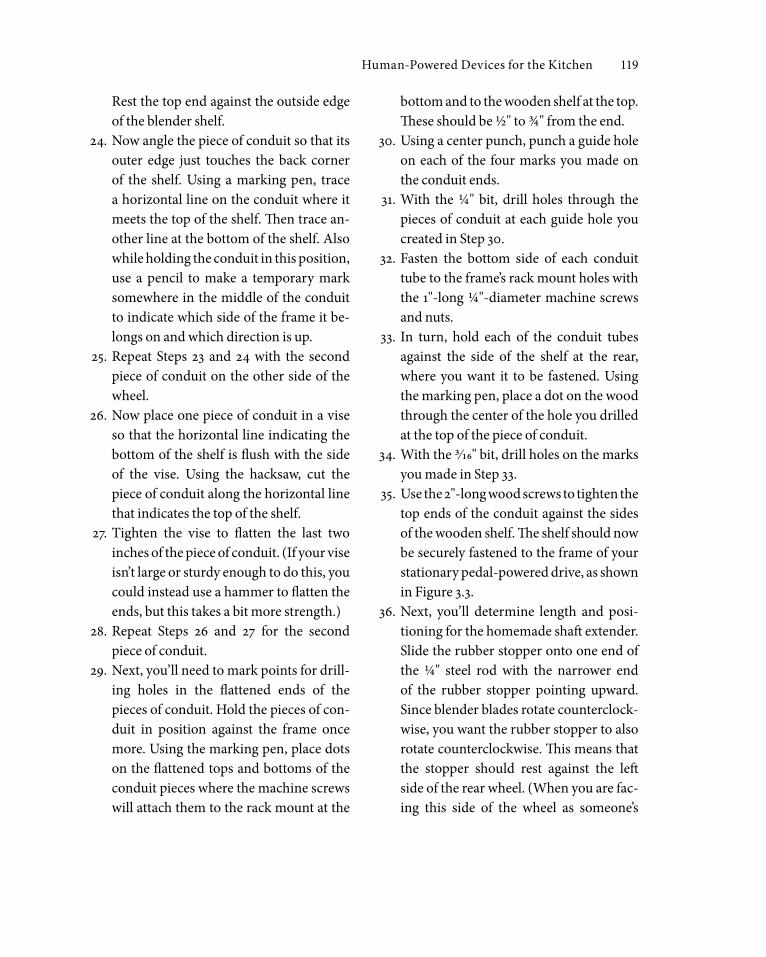
Figure 3.1 Pedal-Powered Blender

Human-Powered Devices for the Kitchen 115
Time to make: 5 hours or lessCost to make: $10 to $25 for scrounged parts
to add to your existing bike and trainer stand
Ease of operation: Moderately easy; however, it can be a real workout if mixing thick liquids
Following is an overview of the steps in this plan:
First, you’ll disassemble your motorized •blender to leave only the necessary me-chanical parts.Next, you’ll construct a shelf for the •blender out of a piece of wood and two pieces of steel conduit and connect this shelf to your bike.Then, you’ll make a shaft from a steel rod •and attach that shaft to the blender’s shaft with a coupling nut.Finally you’ll fasten the blender to its •shelf and add the rubber roller that will rest against the wheel and drive the shaft.
MaterialsBike. A mountain bike will work fine, but •a bike with smoother tires, such as a road bike or hybrid bike, will allow for better transfer of force between the bike’s wheel and the blender shaft. (If all you have is a mountain bike, you can replace the rear tire with a smoother tread, of course.) This plan assumes that your bike has a seat-stay bridge with a center mounting hole, which is common to many bikes; however, it’s easy to modify the plan if your bike doesn’t.Bike trainer stand that fits your bike•
Blender with a square-ended, ¼" metal •shaft in the base of its pitcher. I recom-mend finding an Oster-brand blender. New or old, these are the simplest to con-vert to a friction-drive bicycle blender, and I’ve found them to be readily available from thrift stores for $10 or less. This plan was written to be used with Oster-brand blenders, but other similar styles could probably be substituted. Avoid brands that have plastic cams in the pitcher bases. (I’ve discovered that Hamilton Beach and Kitchen Aid brands are more diffi-cult to convert to bike blenders.) Blend-ers whose electrical systems don’t work, such as those with worn-out motors, are fine for this project.One piece of 2 × 12 dimensional lumber •approximately 12" long to act as a shelf for the blenderTwo 15" lengths of ½" or ¾"-diameter steel •conduit (or tube)One hanger bolt, ¼"-diameter and 3" long •(a hanger bolt has a wood screw on one end and a bolt on the other), plus match-ing washer and nut for bolt endTwo ¼"-diameter machine screws 1" long •and matching nuts for attaching the shelf and its supporting conduit tubes to the bike frame’s rear rack braze-ons or eyeletsTwo wood screws 2" long for connect-•ing the top of the conduit tubes to the wooden shelfFour ¼"-diameter machine screws 4" •long and matching washers and nuts for mounting the blender base to the shelfA rubber stopper approximately 1.5" in di-•ameter, with a pre-drilled center hole, for

116 The Human-Powered Home
the roller.* (If ordering from a lab supply company or buying at a hardware store, choose a Size 8 stopper with a single hole. While it’s possible to drill a hole in a solid rubber stopper, it’s very difficult to make that hole perfectly vertical and centered.) See the variations at the end of this proj-ect for alternative roller possibilities.One ¼"-diameter steel round stock ap-•proximately 10" long*One ¼" to ¼" coarse-thread steel cou-•pling nut*One ¼"-diameter metal shaft collar for •securing the rubber roller in place on the shaft*At least four fender washers no larger •than 1" in diameter with ¼" holes*One ¼"-diameter coarse-thread hex nut •for base of shaft (below roller)*
*Confirm that the shaft inside your blender is ¼" in diameter before purchasing these parts. If your shaft diameter differs, change the size of the steel round stock, coupling nut, shaft collar, washers and nut accordingly.
ToolsMeasuring tape•Permanent marker•Pencil•Safety goggles•Hacksaw•Handsaw or chop saw•Phillips head screwdriver•A set of hex-head socket drivers•Wire cutter•Drill with• 3⁄16",¼" and 5⁄16" bitsDie stock and die for ¼" coarse thread•Vise-grip pliers•
A large vise (on workbench)•Allen wrench small enough to tighten •shaft collarsPliers•Steel square (or similar square)•Center punch•Workbench or other sturdy work surface•
Steps for Making a pedal-powered Blender
1. Secure your bike in the trainer stand. (Follow the manufacturer’s instructions for proper use.) Normally this simply in-volves lining up the rear wheel axle (or skewer) with the cups on the stand, and then tightening those cups against the axle. It’s also helpful to use a piece of wood or a stabilizing block to keep the front wheel from wobbling.
2. Disengage the trainer stand’s resistance mechanism. On many popular trainer stands you do this by loosening the ad-justment knob until the resistance unit no longer touches the rear tire.
3. Now that your bike is fixed in place, you’ll begin to convert your blender.
Note: Do not allow the blender to be plugged in at any point during this project!
4. Remove the pitcher, blade and rubber gasket from the base of your blender and set them aside. You’ll reattach them later.
5. Turn your blender’s base upside down and notice how the bottom panel is attached. Typically, it’s fixed with 3 or 4 screws (they may be Phillips head or socket hex head, for which you’ll need a socket driver). Remove the screws and set them aside. You’ll use them later.

Human-Powered Devices for the Kitchen 117
6. After opening up your blender’s base, get a sense of how the fan and motor are at-tached to the housing. In an Oster-brand blender, the lowermost component is the fan, then above that sits a bracket, the stator (or coil), the rotor, and an-other bracket. All are centered on a ¼" metal shaft. Figure 3.2 illustrates the typi-cal arrangement of parts within an Oster-brand blender base. In the next few steps you’ll remove as much of the blender’s in-terior as necessary to free the shaft for a coupling and extension. With this as the goal, you might need to remove only a fan on your blender, or you might need to re-move virtually everything in the base.
7. Using the wire cutters, snip the electri-cal cord where it terminates inside the blender base. Then remove the electri-cal cord from the blender’s bottom panel and discard. (If it’s not possible to pull the electrical cord out, cut it close to ei-ther side of the bottom panel.) Similarly remove any other wires that might get in your way during Step 8.
8. Remove the fan and the coil and any brackets that fix those to the blender’s base. However, leave the rotor, as it likely contains bearings that will help the blender run even while pedal-powered. You will not need the screws that hold in the fan and the coil. If any screws are nec-essary to attach the rotor’s frame to the base, keep those available for later use.
9. The very end of the blender’s shaft might be threaded like a machine screw. If it is not, skip to Step 10. If the shaft is threaded, check to see whether it fits into the cou-
pling nut that you bought. Chances are it’s fine-threaded, rather than coarse-threaded. If that’s the case, you’ll need to remove the shaft from the blender and re-thread it with the die stock and die, as de-scribed in Steps 10 through 13, then put it back in the blender. However, if the base of the shaft is coarse-threaded and fits in the coupling nut, set aside the blender for now and go to Step 14.
10. Before attempting to remove the shaft from the blender, make sure no screws re-main to fasten any parts inside the base. (That is, make sure the only reason the rotor remains in the base is because the shaft can’t be pulled out.)
11. Lock the square metal drive stud that sticks up above the top of the base with vise-grip pliers. Grab the opposite, lower end of the shaft with pliers and unscrew the shaft from the base. This might take some strength, especially if the blender is old. You should be left with a long piece of
Figure 3.2 Parts Inside a Blender Base

118 The Human-Powered Home
the shaft connected to the rotor (or which-ever parts you couldn’t remove from the blender’s base) and the square drive stud plus a washer from the top side of the blender base. Set aside the drive stud and washer. You’ll reattach them later.
12. Now that you’ve removed the shaft, se-cure it tightly in a vise on a workbench with the end that had pointed toward the bottom of the blender now pointing up-ward. Make sure the shaft is fixed in a ver-tical position.
13. Insert the ¼" coarse thread die in the die stock. Hold the die stock horizontally atop the end of the shaft, then turn it once to the right and begin to cut a new thread. Then turn it backwards to clear the metal out of the thread. (It might take a few tries to set properly.) Repeat the forward and backward rotations until you have cut ap-proximately ¾" of new thread.
14. Using the pliers and vise-grip pliers, re-place the shaft in the blender by connect-ing the square drive stud and washer from the top side of the base to the long shaft you just threaded that goes in the bottom side of the base. Reattach the rotor if it’s held in place with screws. Set aside the blender for now.
15. Next, you’ll make the blender’s shelf and its supports. Hold the 2" × 12" × 12" piece of wood above the rear wheel so that its length is roughly centered over the wheel. Also hold it high enough so that its front face hits the bike’s seat-stay bridge. In the next few steps you’ll mark and cut this face to match the angle of the seat stays.
16. Using a marking pen, draw a line on the wood to indicate the angle of the seat stays where they will meet the 2" plane of the wood.
17. Saw the wood along the diagonal mark that you made in Step 16.
18. The board will be fastened to your bike’s seat-stay bridge along the edge you cut in Step 17 with a hanger bolt. Mark a dot at the intersection of the horizontal and ver-tical center lines on the board face that you cut in Step 17. Also note the angle of the seat-stay bridge mounting hole, if one exists.
19. Using a 3⁄16" bit, drill a hole about ¾" deep on the dot you drew in Step 18. The seat-stay bridge mounting hole is usually an-gled, so drill this hole at an angle that matches it.
20. Screw the wood-screw side of the hanger bolt into the hole you drilled in Step 19.
21. Now insert the bolt side of the hanger bolt in the seat-stay bridge mounting hole and affix the matching washer and nut on the other side of the seat-stay bridge.
22. The board should be held firm and level now by the hanger bolt. However, it’s not yet stable enough to support a function-ing blender. Next, you’ll create two side supports for this shelf from the pieces of steel conduit.
23. Hold a piece of conduit so that one end is about ½" lower than the rack mount braze-on or eyelet at the bottom of the seat stay on one side of the wheel’s axis (making sure that this tolerance will al-low it to lie flat against the rack mount).
Human-Powered Devices for the Kitchen 119
Rest the top end against the outside edge of the blender shelf.
24. Now angle the piece of conduit so that its outer edge just touches the back corner of the shelf. Using a marking pen, trace a horizontal line on the conduit where it meets the top of the shelf. Then trace an-other line at the bottom of the shelf. Also while holding the conduit in this position, use a pencil to make a temporary mark somewhere in the middle of the conduit to indicate which side of the frame it be-longs on and which direction is up.
25. Repeat Steps 23 and 24 with the second piece of conduit on the other side of the wheel.
26. Now place one piece of conduit in a vise so that the horizontal line indicating the bottom of the shelf is flush with the side of the vise. Using the hacksaw, cut the piece of conduit along the horizontal line that indicates the top of the shelf.
27. Tighten the vise to flatten the last two inches of the piece of conduit. (If your vise isn’t large or sturdy enough to do this, you could instead use a hammer to flatten the ends, but this takes a bit more strength.)
28. Repeat Steps 26 and 27 for the second piece of conduit.
29. Next, you’ll need to mark points for drill-ing holes in the flattened ends of the pieces of conduit. Hold the pieces of con-duit in position against the frame once more. Using the marking pen, place dots on the flattened tops and bottoms of the conduit pieces where the machine screws will attach them to the rack mount at the
bottom and to the wooden shelf at the top. These should be ½" to ¾" from the end.
30. Using a center punch, punch a guide hole on each of the four marks you made on the conduit ends.
31. With the ¼" bit, drill holes through the pieces of conduit at each guide hole you created in Step 30.
32. Fasten the bottom side of each conduit tube to the frame’s rack mount holes with the 1"-long ¼"-diameter machine screws and nuts.
33. In turn, hold each of the conduit tubes against the side of the shelf at the rear, where you want it to be fastened. Using the marking pen, place a dot on the wood through the center of the hole you drilled at the top of the piece of conduit.
34. With the 3⁄16" bit, drill holes on the marks you made in Step 33.
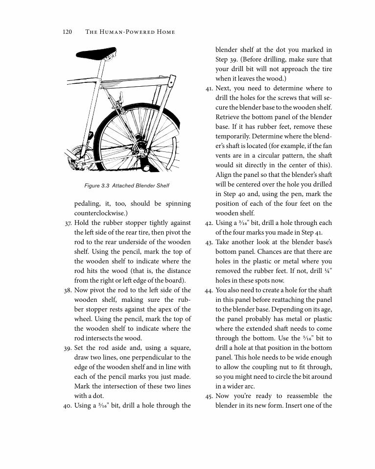
35. Use the 2"-long wood screws to tighten the top ends of the conduit against the sides of the wooden shelf. The shelf should now be securely fastened to the frame of your stationary pedal-powered drive, as shown in Figure 3.3.
36. Next, you’ll determine length and posi-tioning for the homemade shaft extender. Slide the rubber stopper onto one end of the ¼" steel rod with the narrower end of the rubber stopper pointing upward. Since blender blades rotate counterclock-wise, you want the rubber stopper to also rotate counterclockwise. This means that the stopper should rest against the left side of the rear wheel. (When you are fac-ing this side of the wheel as someone’s
120 The Human-Powered Home
pedaling, it, too, should be spinning counterclockwise.)
37. Hold the rubber stopper tightly against the left side of the rear tire, then pivot the rod to the rear underside of the wooden shelf. Using the pencil, mark the top of the wooden shelf to indicate where the rod hits the wood (that is, the distance from the right or left edge of the board).
38. Now pivot the rod to the left side of the wooden shelf, making sure the rub-ber stopper rests against the apex of the wheel. Using the pencil, mark the top of the wooden shelf to indicate where the rod intersects the wood.
39. Set the rod aside and, using a square, draw two lines, one perpendicular to the edge of the wooden shelf and in line with each of the pencil marks you just made. Mark the intersection of these two lines with a dot.
40. Using a 5⁄16" bit, drill a hole through the
blender shelf at the dot you marked in Step 39. (Before drilling, make sure that your drill bit will not approach the tire when it leaves the wood.)
41. Next, you need to determine where to drill the holes for the screws that will se-cure the blender base to the wooden shelf. Retrieve the bottom panel of the blender base. If it has rubber feet, remove these temporarily. Determine where the blend-er’s shaft is located (for example, if the fan vents are in a circular pattern, the shaft would sit directly in the center of this). Align the panel so that the blender’s shaft will be centered over the hole you drilled in Step 40 and, using the pen, mark the position of each of the four feet on the wooden shelf.
42. Using a 3⁄16" bit, drill a hole through each of the four marks you made in Step 41.
43. Take another look at the blender base’s bottom panel. Chances are that there are holes in the plastic or metal where you removed the rubber feet. If not, drill ¼" holes in these spots now.
44. You also need to create a hole for the shaft in this panel before reattaching the panel to the blender base. Depending on its age, the panel probably has metal or plastic where the extended shaft needs to come through the bottom. Use the 5⁄16" bit to drill a hole at that position in the bottom panel. This hole needs to be wide enough to allow the coupling nut to fit through, so you might need to circle the bit around in a wider arc.
45. Now you’re ready to reassemble the blender in its new form. Insert one of the
Figure 3.3 Attached Blender Shelf

Human-Powered Devices for the Kitchen 121
four 4"- long machine screws through the top of the blender’s bottom panel feet and through the rubber feet, so that the machine screws stick out the bottom of the panel. The underside of the blender should now look like the illustration in Figure 3.4. It’s almost ready to mount on the shelf.
46. Using the four screws you removed in Step 5, reattach the bottom panel to the base of the blender. The shaft’s coupling should extend just to or through the hole you drilled in Step 40.
47. Align the blender base so that the cou-pling is centered over the shaft hole and the four machine screws are centered over their holes. Push the machine screws through the four holes so that the blender base rests flush with the top of the wooden shelf.
48. Affix the nuts to secure the machine bolts and hold the blender base tightly in place.
49. Now you’re ready to create the shaft extension. Determine how long this must be by holding the shaft with the rubber roller attached up through the hole you drilled in Step 40 and tight against the coupling.
50. Adjust the rubber roller so that its side rests flush against the tire and so that its bottom edge does not quite reach the tire’s rim. The more surface area touching the tire, the more power you’ll transfer from the rear wheel to the blender. Below the rubber roller you need only enough length to attach one of the collars and a hex nut, or about ¾". Use the pen to draw
a line that indicates where the bottom of the shaft extension should fall.
51. Remove the rubber roller from the shaft extension and, using the hacksaw, cut the steel rod at the mark you made in Step 50.
52. Follow Step 13 to cut a thread on both ends of the shaft extension.
53. Insert one end of the shaft extension up through the blender’s shaft hole in the wooden shelf and, while holding the small square end of the shaft that sticks up above the base in a vise grip, tighten the shaft extension into the coupler. Now your blender’s shaft is extended to reach the rear tire.
54. At the other end of the shaft attach the metal shaft collar in a position just above where the top of the rubber roller will fall. Tighten it with the appropriate Allen wrench.
55. Add a fender washer below the shaft collar.
56. Next, add the rubber roller to the shaft so that it’s tight against the fender washer and shaft collar above it.
Figure 3.4 Underside of Blender Ready For Mounting

122 The Human-Powered Home
57. Add a fender washer below the rubber roller. If you miscalculated and left too much room between the bottom of the rubber roller and the threaded shaft end, you can fill the space with a few additional fender washers now.
58. Finally, add the ¼" hex nut below the lower collar. Tighten securely. Try turn-ing the rear wheel to make sure the whole shaft rotates when the wheel causes the rubber roller to rotate. If the roller sim-ply revolves around the shaft, you need to compress it more firmly between the shaft collar, washers and hex nut. The end of the shaft should now look like the dia-gram in Figure 3.5.
Handcrafting soap requires a lot of mixing . Frederick Breeden of Just Soap makes soaps, salves and shampoos for over 100 retailers across the US . At first he mixed the batches by hand, but as business grew, this proved too slow, not to mention exhausting . Yet he couldn’t justify buying a big electric mixer . Being a pas-sionate recreational and commuter bicyclist, Frederick knew the power of leg muscles . So he wondered whether it was possible to run a soap mixer with a bicycle . He searched local bike shops and found a skilled bicycle builder who shared his enthusiasm for the idea . Together they engineered what Frederick calls “a beauti-ful, wonder fully built machine .” Still, it was a gam-ble . “I was spending all this money and we had no idea whether a human could mix in a sufficient way that the whole thing becomes homogenous and uniform .”
But the bicycle blender worked well . In fact, Frederick was surprised at how easy it was to
Frederick Breeden and Just Soap
Figure 3.6 Frederick Breeden and His Bicycle-Powered Soap Blender
Figure 3.5 Rubber Stopper Affixed to Blender Shaft

Human-Powered Devices for the Kitchen 123
59. Reposition the rubber gasket, blade and pitcher on the blender’s base.
60. Get seated, cycle and test your pedal-powered blender.
Variations and ConsiderationsIf your bike already has a rear rack, you •can use that as a base for mounting the blender on the back of the bike, rather than making a shelf from wood and sup-ports from electrical conduit.If you don’t have a bike trainer stand, you •can make your own using angle iron or another frame-suitable material.The larger the wheel, the greater the gear •ratio between the wheel and rubber stop-
per. This will help you spin the blender’s shaft at higher rpm.Many small, round objects can be sub-•stituted for the rubber roller. To give the bike blender greater longevity and dura-bility, some inventors use a rollerblade wheel. However, you first need to remove the central bearings from these wheels; otherwise the shaft will spin within the rollerblade wheel, and force from your bicycle wheel will not be transferred to the blender shaft. You could also make a roller out of a drum sander attachment for a drill whose shaft is the same size as your blender’s extended shaft. (I’ve tried this with success, too.)
pedal . The only changes made to the original design were to add a fixed gear on the back to allow Frederick to pedal both forwards and back-wards and to substitute a larger flywheel, thereby giving the mixer more speed .
To mix one batch of soap, or 440 pounds of liquid, he pedals between 20 to 90 minutes, often in intervals of 5 minutes of pedaling and 5 minutes of resting . Timing depends on the char-acteristics of each batch — and this is where pedal-powered blending trumps motor-powered blending . As the mixture of oil and lye begins to thicken, pedaling becomes increasingly more dif-ficult, and Frederick can sense how close the batch is to being finished . “I have to be totally aware and concentrating on the soap because otherwise it’s going to go past the point where I can control it . . . . [I’m] getting a feel for the partic-ular batch . I like the connection .” Frederick also appreciates that with no motor running, making soap is a quiet activity .
After 8 years of regular use and despite its large number of working parts, the bicycle blender has required absolutely no maintenance . It works as well today as it did on day one . “I don’t know how many motors would have lasted that long or whether a commercial mixer would have lasted that long,” Frederick told me .
Business at Just Soap is brisk and growing . Besides preferring Frederick’s products, some customers especially admire his bike-blending process . “It definitely appeals to people who are interested in alternative ways of manufacturing, who like that I’m small-scale, but able to produce in a way that can sufficiently make the product and keep the prices low . A lot of folks like me be-cause they’re cyclists and they love seeing things done with pedal power .” Frederick has even been asked whether he’d sell the machine or the plans to make it . So far his answer has been “no .”2

124 The Human-Powered Home
If your bike doesn’t have a seat-stay •bridge, you can still insert the hanger bolt as described in Steps 18 through 20. How-ever, rather than fasten the bolt through a seat-stay bridge mounting hole, use a mending plate wide enough to span both seat stays on the opposite side of the seat stays from the blender shelf. Drill a hole in the mending plate that lines up with your hanger bolt. Then secure the mend-ing plate against the seat stays by tighten-ing the appropriate nut on the bolt.Because it’s convenient to face the blender •while mixing liquids, you could use a sta-tionary bike, on which the front wheel ro-tates, as the pedal-power drive, creating a shelf for the blender that’s suspended from the head tube and the front wheel’s axle.
If you prefer to mix while mobile, try tak-•ing your bike out of the trainer stand and blending as you cycle.
Plan for Converting a hand-Cranked grain mill to Pedal PowerIf you grind your own wheat berries into flour just before baking, you know how much bet-ter it tastes than purchased flour ground far away and who knows when. Grinding grain requires little enough effort to be easily hu-man powered. However, grinding by hand can get tiresome. Some people connect their hand-cranked grain grinder to a stationary bike to make the work easier. This plan de-scribes one way of doing that.
Several manufacturers make hand-cranked grain mills, and although they might look different, all follow a common design. A
Figure 3.7 Hand-Cranked Grain Mill Converted to Pedal Power