placement of endosteal implants in the zygoma after ... · placement of endosteal implants in the...
TRANSCRIPT
Placement of Endosteal Implants in theZygoma after Maxillectomy: A Cadaver StudyUsing Surgical NavigationFranz Watzinger, M.D., Wolfgang Birkfellner, M.Sc., Felix Wanschitz, M.D., Farzad Ziya, M.D.,Arne Wagner, M.D., Judith Kremser, M.Sc., Franz Kainberger, M.D., Klaus Huber, M.Sc.,Helmar Bergmann, Ph.D., and Rolf Ewers, M.D., D.D.S.Vienna, Austria
Endosteal implants facilitate obturator prosthesis fixa-tion in tumor patients after maxillectomy. Previous clin-ical studies have shown, however, that the survival of im-plants placed into available bone after maxillectomy isgenerally poor. Nevertheless, implants positioned opti-mally in residual zygomatic bone provide superior stabilityfrom a biomechanical point of view. In a pilot study, theauthors assessed the precision of VISIT, a computer-aidedsurgical navigation system dedicated to the placement ofendosteal implants in the maxillofacial area. Five cadaverspecimens underwent hemimaxillectomy. The cadaverhead was matched to a preoperative high-resolution com-puted tomograph by using implanted surgical micro-screws as fiducial markers. The position of a surgical drillrelative to the cadaver head was determined with an op-tical tracking system. Implants were placed into the zygo-matic arch, where maximum bone volume was available.The results were assessed using tests for localization ac-curacy and postoperative computed tomographic scans ofthe cadaver specimens. The localization accuracy of land-marks on the bony skull was 0.6 6 0.3 mm (average 6 SD),as determined with a 5-df pointer probe; the localizationaccuracy of the tip of the implant burr was 1.7 6 0.4 mm.The accuracy of the implant position compared with theplanned position was 1.3 6 0.8 mm for the external per-foration of the zygoma and 1.7 61.3 mm for the internalperforation. Eight of 10 implants were inserted with max-imal contact to surrounding bone, and two implants werelocated unfavorably. Reliable placement of implants inthis region is difficult to achieve. The technique describedin this article may be very helpful in the management ofpatients after maxillary resection with poor support forobturator prostheses. (Plast. Reconstr. Surg. 107: 659,2001.)
The prosthetic supply for patients after max-illectomy exhibits a number of problems. Soft-
tissue shrinkage resulting from a lack of sup-port from underlying bone often prevents sat-isfactory long-term aesthetic and functional re-habilitation. Proper sealing of the nasopharynxtoward the oral cavity is essential for phoneticfunction and swallowing. Myocutaneous or os-teomyocutaneous microvascular flaps arewidely used to achieve this goal.1–4 Immediateflap surgery may, however, prevent the earlydetection of residual or recurrent cancer.5
When flap reconstruction is not indicated, anobturator prosthesis enables functionally andaesthetically satisfying rehabilitation.4,6–9
Often a sufficient retention of the obturatorprosthesis can be achieved without additionalanchorage. If retention is not sufficient, os-seointegrated implants can be used for pros-thesis fixation.6,10–12 Two problems with en-dosteal implant placement arise in these cases.First, bone in close proximity to the resectioncavity is usually sparse. In most cases, only theroot of the zygomatic arch offers sufficientbone volume for implant placement. Second,implant osseointegration is often delayed byprevious irradiation treatment.13
Roumanas et al.14 published the largest col-lective of patients treated with placement ofendosteal implants after maxillectomy: 102 im-plants were inserted in 26 cases. The overallrate of implant survival was 69.2 percent. Forpatients with additional irradiation treatment,the implant survival rate was 63.6 percent,
From the University Clinic of Oral and Maxillofacial Surgery, and the University Clinic of Diagnostic Radiology, Department of Osteoradiology,Medical School; the Department of Biomedical Engineering and Physics, and the Ludwig-Boltzmann Institute of Nuclear Medicine, GeneralHospital; and the Institute of Anatomy; University of Vienna. Received for publication October 29, 1999; revised May 16, 2000.
659
whereas a survival rate of 82.6 percent wasreported in nonirradiated patients. The sur-vival rate of the implants placed close to themaxillectomy defect was poor (33 percent);however, this percentage is not significant be-cause of only six implants being inserted.
Fixing the obturator prosthesis on implantsplaced in the contralateral maxilla is biome-chanically problematic because the prosthesisforms a long lever. The intense mechanicalstress on the implant shaft leads to the loss ofperi-implant bone.15,16 The bilateral placementof implants avoids excessive biomechanicalstress, resulting in longer implant survival.17
The purpose of this study was to assess thepossibility of optimizing the placement of en-dosteal implants in patients after maxillectomyby means of computer-aided navigation tech-niques.18 –24 Computer-aided surgery is cur-rently used in various surgical specialities, forinstance, in stereotactic neurosurgical proce-dures and for pedicle screw insertion in spinesurgery. In craniofacial and maxillofacial sur-gery, computer-aided surgery is introduced forvarious indications. A cadaver study for theevaluation of a specialized navigation systemdeveloped for the placement of endosteal im-plants is presented.
MATERIALS AND METHODS
Hardware and Software
VISIT, a modular software system for thedevelopment of exploratory software for surgi-cal applications, was used in this study. VISIT isbased on AVW 2.5, a software library dedicatedto biomedical image processing (BiomedicalImaging Resource, Mayo Clinic, Rochester,Minn.).25 Surgical instruments and patient mo-tion were tracked using an optical positionmeasurement system (Flashpoint 5000, ImageGuided Technologies Inc., Boulder, Colo.).Accuracy of the system was found to be in thevicinity of 1 mm.26,27 The workstation used wasa Sun UltraSPARC 10 (Sun Microsystems, PaloAlto, Calif.). The software system was devel-oped for implant dentistry and was used with-out modification for the experiments.28
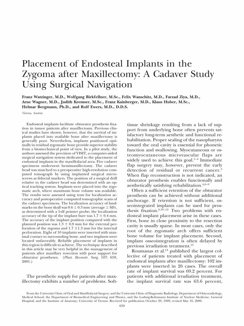
Because the position of the drill bit relativeto the optical probe (V-probe) must be deter-mined intraoperatively to visualize the positionand direction of the drill bit, a special-calibration light-emitting diode assembly wasdeveloped. This calibration probe contains aprecision-machined titanium inlay that
matches a 2-mm pilot drill. By inserting thedrill into this sterilized calibration probe, ageometric relation (referred to as offset vec-tor) can be determined intraoperatively (Fig.1).
Preoperative Imaging and Planning
The initial precision tests and preliminaryplanning procedures were performed on amacerated bony skull. Then, five cadaver headsunderwent a left hemimaxillectomy that pre-served the orbital floor and the zygomatic arch.To match the coordinate system of a sensorassembly mounted to the skull with the coor-dinate system of the computed tomograph,miniature titanium screws (Leibinger AG,Freiburg, Germany) were inserted in the peri-orbital region and the zygomatic arch. Thesescrews are referred to as fiducial markers inthis article.
High-resolution computed tomographicscans were done on a Philips Tomoscan 7000SR (Philips AG, Best, The Netherlands). Theresolution of the resulting volume image was0.35 3 0.35 3 1.00 mm3. Preoperative plan-ning was performed by determining a startingpoint and a second point that defined the di-rection of the implant on the axial computedtomographic slices (Fig. 2). The implant posi-tion was assessed and corrected if necessary byusing multiplanar orthogonally reformattedaxial, coronal, and sagittal slices. In a secondstep, the planned implant positions were alsovisualized using transparent volume render-ings of the bone.
FIG. 1. Tool set for intraoperative computer navigation:(a) 5-df probe for intraoperative registration, (b) referencesensor, (c) sensor assembly mounted on a drill handle, (d)calibration tool (drill calibration).
660 PLASTIC AND RECONSTRUCTIVE SURGERY, March 2001

Registration
To compute a mathematical transformationthat conveys the coordinate system of the com-puted tomographic scan to the patient (usuallyreferred to as patient-to-scan registration), anLED emitter array was attached to the skull ofthe cadaver specimens by using a single tita-nium osteosynthesis screw. All position data ofsurgical tools are reported relative to the posi-tion of this emitter array, thus making the fix-ation of the patient by means of an externalhead-frame, such as in neurosurgical proce-dures, unnecessary29 (Fig. 3).
For patient-to-scan registration, at least threeof the preoperatively inserted titanium micro-screws must be identified on the patient, usingthe 5-df pointer probe, and on the computedtomographic volume image. The mathematicalregistration transformation that translates theposition of a surgical instrument relative to thereference sensor from the cadaver head to the
scan was computed by the algorithm given byHorn.30
Visualization
The aim of our surgical navigation system isto position endosteal implants in exact agree-ment with the preoperative plan. For generalorientation in the operating field, transparentvolume renderings were generated that dis-played both the bone surface and the plannedimplants. The position of the drill tip was pro-jected into frontal and lateral renderings inreal time (Fig. 4, above).
The position of the drill was also visualizedon obliquely reformatted computed tomo-graphic slices. Two slices are perpendicular toeach other, intersecting the axis of the drill.The third slice is in normal position with thedrill axis and touches the tip of the drill. Whenthe drill matches the preoperative planning,the implants appear in full length and diame-
FIG. 2. Computer screen for preoperative planning. After choosing a startpoint (red points on the left axial computed tomographic scan) and an endpoint of theimplant (yellow circles), the position of the implant channel is visualized in threeorthogonal reformatted views (green channels on the right half of the image).
Vol. 107, No. 3 / ENDOSTEAL IMPLANTS AFTER MAXILLECTOMY 661

ter on the reformatted slices (Fig. 4, below). Allimages are updated twice per second with ref-erence to the drill position.
Surgical Procedure
Because of the limited space, the implantsockets were drilled using an extraoral ap-proach. This approach can be easily trans-ferred to the patient because only a small inci-sion is necessary and the zygoma need not beexposed. Implant sockets were drilled in bothzygomatic bones in each cadaver specimen.The implant sockets were marked with ra-diopaque gutta-percha points. For postopera-tive evaluation, a computed tomographic scanwith parameters identical to those of the pre-operative scan was performed.
Evaluation of System Performance
Preliminary evaluation of the system’s preci-sion was performed after registration by com-paring the position readings of the osteosyn-thesis screws used as fiducial markers with theposition readings in the computed tomo-graphic volume using the 5-df probe. The ac-curacy level of the drill calibration was deter-mined similarly.
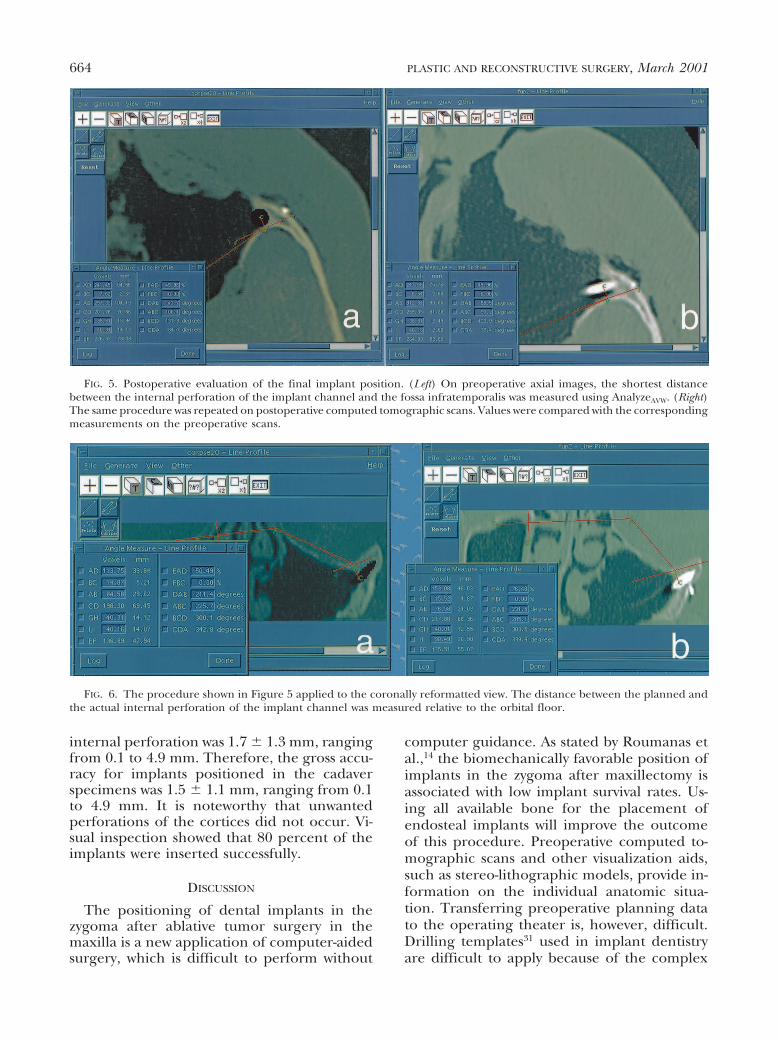
To evaluate the final results, both the preop-erative computed tomographic scans contain-ing the surgical plan and the postoperativescans with the gutta-percha points in situ wereloaded into a medical image processing soft-ware package (AnalyzeAVW, Biomedical Imag-
ing Resource). A tangent to the bone of theorbital floor (of-tangent) was drawn on coro-nally reformatted computed tomographicscans, and a tangent to the infratemporal fossa(if-tangent) was constructed on the originalaxial scans. Virtual points marked the regionwhere the implants perforated the zygomaticbone on the outer surface (external perfora-tion) and on the inner surface (internal perfo-ration). The shortest distance from these twopoints to the tangents were measured on boththe preoperative and postoperative computedtomographic scans (Figs. 5 and 6). These datawere analyzed using Excel 5.0 (Microsoft, Red-mont, Wash.). Accuracy was assessed by calcu-lating the average value of the deviations fromthe positions on the preoperative computedtomographic scans compared with those onthe postoperative scans. The experimental er-ror was given as the empirical SD of thesemeasurements, calculated as follows:
s 5 ÎOi51N ~x# 2 xi!
2
N 2 1,
where s is the square root of the empiricalvariance (5 SD), N is the number of singlemeasurements, xi is a single measurement, andx with an overbar is the arithmetic mean of thesingle measurements.
RESULTS
The average localization accuracy of thepointer probe on 28 microscrews was 0.6 6 0.3mm, ranging from 0.2 to 1.0 mm. This devia-tion was the same for the screws that were usedas fiducial markers for registration as for thosethat were not. The same procedure repeatedwith the pilot drill on 28 microscrews resultedin an average deviation of 1.7 6 0.4 mm, rang-ing from 0.9 to 3.0 mm. Table I shows allmeasurements concerning the relative devia-tion of planned and postoperative implant dis-tances from the fossa infratemporalis tangent(axial slice orientation) and the orbital floortangent (coronally reformatted slices). Themeasurements were performed on 10 implantsin five specimens, and the data were analyzedusing Microsoft Excel 5.0.
The average deviation from the preopera-tively planned external perforation of the im-plant channel was 1.3 6 0.8 mm, ranging from0.1 to 2.8 mm. The average deviation of the
FIG. 3. Registration procedure: positions of four micro-screws are measured with the 5-df probe relative to the ref-erence sensor mounted to the forehead. These values areused for matching the coordinate systems of the head’s ref-erence sensor to the computed tomographic coordinatesystem.
662 PLASTIC AND RECONSTRUCTIVE SURGERY, March 2001
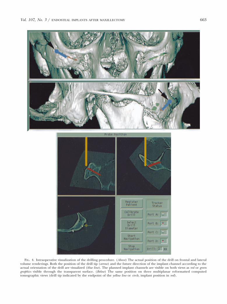
FIG. 4. Intraoperative visualization of the drilling procedure. (Above) The actual position of the drill on frontal and lateralvolume renderings. Both the position of the drill tip (arrow) and the future direction of the implant channel according to theactual orientation of the drill are visualized (blue line). The planned implant channels are visible on both views as red or greengraphics visible through the transparent surface. (Below) The same position on three multiplanar reformatted computedtomographic views (drill tip indicated by the endpoint of the yellow line or circle, implant position in red).
Vol. 107, No. 3 / ENDOSTEAL IMPLANTS AFTER MAXILLECTOMY 663
internal perforation was 1.7 6 1.3 mm, rangingfrom 0.1 to 4.9 mm. Therefore, the gross accu-racy for implants positioned in the cadaverspecimens was 1.5 6 1.1 mm, ranging from 0.1to 4.9 mm. It is noteworthy that unwantedperforations of the cortices did not occur. Vi-sual inspection showed that 80 percent of theimplants were inserted successfully.
DISCUSSION
The positioning of dental implants in thezygoma after ablative tumor surgery in themaxilla is a new application of computer-aidedsurgery, which is difficult to perform without
computer guidance. As stated by Roumanas etal.,14 the biomechanically favorable position ofimplants in the zygoma after maxillectomy isassociated with low implant survival rates. Us-ing all available bone for the placement ofendosteal implants will improve the outcomeof this procedure. Preoperative computed to-mographic scans and other visualization aids,such as stereo-lithographic models, provide in-formation on the individual anatomic situa-tion. Transferring preoperative planning datato the operating theater is, however, difficult.Drilling templates31 used in implant dentistryare difficult to apply because of the complex
FIG. 5. Postoperative evaluation of the final implant position. (Left) On preoperative axial images, the shortest distancebetween the internal perforation of the implant channel and the fossa infratemporalis was measured using AnalyzeAVW. (Right)The same procedure was repeated on postoperative computed tomographic scans. Values were compared with the correspondingmeasurements on the preoperative scans.
FIG. 6. The procedure shown in Figure 5 applied to the coronally reformatted view. The distance between the planned andthe actual internal perforation of the implant channel was measured relative to the orbital floor.
664 PLASTIC AND RECONSTRUCTIVE SURGERY, March 2001

intraoperative situation. Computer-aided sur-gery was applied in implant dentistry in a num-ber of clinical trials. The first efforts32 sufferedfrom problems in the electromagnetic trackinghardware used.33 The further development ofthis technique involved improved sensortechnology.24
A crucial point is the intraoperative usabilityand the reliability of such a navigation system.Concerning the latter, the results presentedabove seem to be appropriate. The direction ofthe surgical drill cannot be assessed visually bythe surgeon because of the minimal invasiveapproach to the zygomatic arch. The localiza-tion accuracy of the microscrews measuredwith the 5-df probe was excellent (0.6 6 0.3mm, 1.1 maximum) compared with the resolu-tion of approximately 1 mm of the high-resolution computed tomographic scans. Thelocalization error of the tip of the implant burris higher (deviation 1.7 mm 6 0.4 mm, maxi-mum 3.0 mm), correlating well with the aver-age postoperative accuracy of 1.5 6 1.1 mm.This indicates that the V-probe and the intra-operative drill calibration procedure may re-quire further improvement. Nevertheless, 8 of10 implants in this study were placed in a sat-isfactory position. Two implants were in anunfavorable position: one was inserted consid-
erably too steep compared with the surgicalplan; the other was situated too far posteriorly.These problems occurred mainly because ofthe difficulty in maintaining good correlationof the implant burr and the planned axis of theimplant. Deviations were induced by such me-chanical problems as the mobility of the im-plant burr in the drill’s bearing and the deflec-tion of the drill on its way through the bonebecause of anatomic factors. Because these twoimplants were planned in a very steep manner,we assume that this problem can be avoided bypenetrating the cortex as perpendicularly aspossible. Improved visualization techniquesand the use of head-mounted displays mightimprove the accuracy of the procedure.
In conclusion, the success rate of 80 percentis impressive in a procedure that cannot beperformed by using this minimal invasive ap-proach without computer navigation. There-fore, in consideration of the results of the ca-daver study, we think that clinical application isjustified. Further refinement of the opticaltracking probes also may improve the resolu-tion accuracy of the computed tomographicscan used. This resolution, which is typically 1mm in the case of conventional high-resolutioncomputed tomography, is also the theoreticallimit of the system.
TABLE IMeasurements of the Relative Deviation of Planned and Postoperative Implant Distances from the Fossa Infratemporalis
Tangent and the Orbital Floor Tangent
Cadaver SpecimenNo.
Position on Skull/CT*Slice Orientation
External Perforation(difference in mm)
Internal Perforation(difference in mm)
I Right/axial 1 1.4Left/axial 1.4 0.1
Right/coronal 2.8 2.4Left/coronal 1.2 1.3
II Right/axial 1.3 1.9Left/axial 1.4 0.5
Right/coronal 1.5 0.7Left/coronal 1 1.4
III Right/axial 1.4 1Left/axial 1.4 0.5
Right/coronal 2.7 2.5Left/coronal 0.8 1.3
IV Right/axial 0.2 2.6Left/axial 1.2 1.3
Right/coronal 0.9 4.8Left/coronal 2.7 4.9
V Right/axial 1 1.9Left/axial 0.7 1
Right/coronal 0.1 3Left/coronal 0.2 0.2
Average 1.3 1.7Standard Deviation 0.8 1.3Range 0.1–2.8 0.1–4.9
* CT, computed tomographic.
Vol. 107, No. 3 / ENDOSTEAL IMPLANTS AFTER MAXILLECTOMY 665
ACKNOWLEDGMENTS
Part of the work for developing VISIT was supported by theAustrian Science Foundation FWF under research grantP-12464-MED. A. Gamperl, W. Zawodsky (Department of Bio-medical Engineering and Physics), W. Piller (Ludwig-Boltz-mann Institute of Nuclear Medicine), L. Chamberlain, D.Dick (Image Guided Technologies Inc., Boulder, Colo.), andthe staff at BIR, especially A. Larson and D. Hanson, helpedto solve numerous hard- and software problems. AnalyzeAVW
and AVW were provided courtesy of Dr. R. A. Robb (Bio-medical Imaging Resource, Mayo Clinic, Rochester, Minn.).S. Plischke (Department of Osteoradiology) made the pre-operative and postoperative computed tomographic scans.We thank all of these individuals for their efforts.
Franz Watzinger, M.D.University Clinic of Oral and Maxillofacial
SurgeryGeneral HospitalUniversity of ViennaWaehringerguertel 18-20A-1090 Vienna, [email protected]
REFERENCES
1. Obwegeser, H. L. Late reconstruction of large maxillarydefects after tumour-resection. J. Maxillofac. Surg. 1:19, 1973.
2. Riediger, D. Restoration of masticatory function by mi-crosurgically revascularized iliac crest bone grafts us-ing enosseous implants. Plast. Reconstr. Surg. 81: 861,1988.
3. Izzo, S. R., Berger, J. R., Joseph, A. C., and Lazow,S. K. Reconstruction after total maxillectomy usingan implant retained prosthesis: A case report. Int.J. Oral Maxillofac. Implants 9: 593, 1994.
4. Swartz, W. M., Banis, J. C., Newton, E. D., Ramasatry, S. S.,Jones, N. F., and Acland, R. The osteocutaneousscapular flap for mandibular and maxillary recon-struction. Plast. Reconstr. Surg. 77: 530, 1996.
5. Panje, W. R., Hetherington, H. E., Toljanic, J., La Velle,W. E., and Fyler, A. Bilateral maxillectomy and mid-facial reconstruction. Ann. Otol. Rhinol. Laryngol. 104:845, 1995.
6. Lorant, J. A., Roumanas, E., Nishimura, R., Beumer, J.,III, and Wagman, L. D. Restoration of oral functionafter maxillectomy with osseous integrated implantretained maxillary obturators. Am. J. Surg. 168: 412,1994.
7. Ehrenfeld, M., and Riediger, D. Zur Einheilung freierund mikrochirurgisch revaskularisierter Becken-kammtransplantate. In A. Panicke and H. Rudolph(Eds.), Entwicklung und heutiger Stand der Plastischenund Wiederherstellungschirurgie. Wümme, Rothenburg:Sasse, 1989. P. 358.
8. Vuillemin, T., Raveh, J., Lädrach, K., and Roux,M. Rekonstruktion nach Hemimaxillektomie.Schweiz. Monatsschr. Zahnmed. 100: 1082, 1990.
9. Weischer, T., Schettler, D., and Mohr, C. Titanium im-plants in the zygoma as retaining elements after hemi-maxillectomy. Int. J. Oral Maxillofac. Implants 12: 211,1997.
10. Parel, S. M., Branemark, P. I., and Jansson, T.Osseointegration in maxillofacial prosthetics. Part I.Intraoral applications. J. Prosthet. Dent. 55: 490, 1986.
11. Block, M. S., Guerra, L. R., Kent, J. N., and Finger,I. M. Hemimaxillectomy prosthesis stabilization withhydroxyapatite coated implants: A case report. Int.J. Oral Maxillofac. Implants 2: 111, 1987.
12. Mentag, P. J., and Kosinski, T. F. Increased retention ofa maxillary obturator prosthesis using osteointegratedintramobile cylinder dental implants: A clinical re-port. J. Prosthet. Dent. 60: 411, 1988.
13. Niimi, A., Ueda, M., and Kaneda, T. Maxillary obturatorsupported by osseointegrated implants placed in ir-radiated bone: Report of cases. J. Oral Maxillofac. Surg.51: 801, 1993.
14. Roumanas, E. D., Nishimura, R. D., Davis, B. K., andBeumer, J., III. Clinical evaluation of implants re-taining edentulous maxillary obturator prostheses.J. Prosthet. Dent. 77:184, 1997.
15. Horshaw, S. J., Brunski, J. B., and Cochran, G. Mechani-cal loading of Branemark implants affects interfacialbone modelling and remodelling. Int. J. Oral Maxillo-fac. Implants 9: 345, 1994.
16. Quirynen, M., Naert, I., and van Steenberghe, D. Fix-ture design and overload influence marginal bone lossand fixture success in the Branemark system. Clin. OralImplants Res. 3: 104, 1992.
17. Gary, J. J., Donovan, M., Garner, F. T., and Faulk,J. E. Rehabilitation with calvarial bone grafts andosseointegrated implants after partial maxillary resec-tion: A clinical report. J. Prosthet. Dent. 67: 743, 1992.
18. Taylor, R. H., Lavallée, S., Burdea, G. C., and Mösges, R.(Eds.). Computer-Integrated Surgery: Technology andClinical Applications. Cambridge: MIT Press, 1996.
19. Cutting, C., Bookstein, F. L., Grayson, B., Fellingham, L.,and McCarthy, J. G. Three-dimensional computer-assisted design of craniofacial surgical procedures:Optimization and interaction with cephalometric CT-based models. Plast. Reconstr. Surg. 77: 877, 1986.
20. Cutting, C., Grayson, B., McCarthy, J. G., et al. A virtualreality system for bone fragment positioning in mul-tisegment craniofacial surgical procedures. Plast. Re-constr. Surg. 102: 2436, 1998.
21. Wagner, A., Ploder, O., Enislidis, G., Truppe, M., andEwers, R. Image-guided surgery. Int. J. Oral Maxillo-fac. Surg. 25: 147, 1996.
22. Watzinger, F., Wanschitz, F., Wagner, A., et al. Com-puter-aided navigation in secondary reconstruction ofpost-traumatic deformities of the zygoma. J. Crani-omaxillofac. Surg. 25: 198, 1997.
23. Watzinger, F., Wanschitz, F., Rasse, M., et al. Computer-aided surgery in distraction osteogenesis of the max-illa and mandible. Int. J. Oral Maxillofac. Surg. 28: 171,1999.
24. Watzinger, F., Birkfellner, W., Wanschitz, F., et al. Po-sitioning of dental implants using computer-aidednavigation and an optical tracking system: Case reportand presentation of a new method. J. Craniomaxillofac.Surg. 27: 77, 1999.
25. Robb, R. A. Three-Dimensional Biomedical Image Process-ing. Principles and Practice. Weinheim: VCH, 1995.
26. Kaus, M., Steinmeier, R., Sporer, T., Ganslandt, O., andFahlbusch, R. Technical accuracy of a neuronaviga-tion system measured with a high-precision mechan-ical micromanipulator. Neurosurgery 41: 1431, 1997.
27. Tebo, S. A., Leopold, D. A., Long, D. M., and Zinreich,S. J. An optical 3D digitizer for frameless stereotacticsurgery. IEEE Comput. Graphics P. 55, 1996.
666 PLASTIC AND RECONSTRUCTIVE SURGERY, March 2001

28. Birkfellner, W., Solar, P., and Gahleitner, A. In-vitroassessment of a registration protocol for image guidedimplant dentistry. Clin. Oral Implants Res. In press.
29. Giorgi, C., Luzzara, M., Casolino, D. S., and Ongania,E. A computer controlled stereotactic arm: Virtualreality in neurosurgical procedures. Acta Neurochir.Suppl. 58: 75, 1993.
30. Horn, B. K. P. Closed form solution of absolute orienta-tion using unit quaternions. J. Opt. Soc. Am. 4: 629, 1987.
31. Fortin, T., Coudert, J. L., Champleboux, G., Sautot, P.,
and Lavallée, S. Computer-assisted dental implantsurgery using computed tomography. J. Image Guid.Surg. 1: 53, 1995.
32. Ploder, O., Wagner, A., Enislidis, G., and Ewers,R. Computergestützte intraoperative Visual-isierung von dentalen Implantaten. Radiologe 35:569, 1995.
33. Birkfellner, W., Watzinger, F., Wanschitz, F., et al. Sys-tematic distortions in magnetic position digitizers,Med. Phys. 25: 2242, 1998.
Vol. 107, No. 3 / ENDOSTEAL IMPLANTS AFTER MAXILLECTOMY 667