pl7-3 application converter - schneider electric · pl7-3 application converter w915905150301a_01...
TRANSCRIPT

PL7-3 application converterW
9159
0515
0301
A_0
1
March 2005eng
front1_eng_PM6_convPL73.fm Page 1 Monday, January 10, 2005 11:14 AM

___________________________________________________________________________1
PL7-3 application converter
Section Page
1 Presentation of the converter 3
1.1 Introduction 3
1.2 Modular save of the PL7-3 application 5
1.3 Procedure for converting PL7-3 modules to PL7 6
2 Module conversion 9
2.1 Accessing the converter 9
2.2 Choosing the modules to be converted 92.2-1 Selecting the program module 112.2-2 Analysis and reassignment of objects 13
2.3 Result of the conversion 17
2.4 Reconfiguring PL7 objects 20
2.5 Importing the converted file into PL7 21
2.6 Correspondence file 23
3 Appendix 25
3.1 Correspondence between PL7-3 and PL7 objects 25
3.2 Differences between PL7-3 and PL7 33
PL7-3 application converter 37

___________________________________________________________________________
2

Presentation of the converter
___________________________________________________________________________3
1.1 Introduction
The PL7-3 converter is used to convert the various modules of a PL7-3 application toPL7. This modular conversion thus requires firstly that the PL7-3 application is savedas a source modules : program modules (PRL, POST, CHART, etc), symbol or constantsfile.The binary file (.BIN), which contains the whole application, may be needed to retrievesome information on the software configuration which it has not been possible to saveas a source file (such as the preset value of standard function blocks).Although it is integrated into PL7, installation of this conversion tool is optional, in ordernot to "overload" those users who have no use for it.
Once this converter is installed, it can convert :
• The symbols and comments, contained in an .SCY file,
• The constants, contained in a .CST file,
• The Ladder language rungs of a PL7-3 program module (MAIN, PRL, POST, SRi,contents of a Grafcet step, contents of a transition condition), contained in a .LAD file,
• The program lines of a PL7-3 program module (MAIN, PRL, POST, SRi, contents ofa Grafcet step, contents of a transition condition), contained in an .LIT file,
• The Grafcet pages of a PL7-3 program module (CHART, XMi), contained in a .GR7file. Depending on the choice made when archiving the module under PL7-3, theLadder or Structured Text code contained in its steps and transitions may or may notbe included.
NoteThe source files (.LAD, .LIT, .GR7) at the converter input must be in non symbol form (withoutsymbols). However, they can be associated with a symbols file (.SCY) and/or a constants file(.CST). In this case, the symbols and/or constants contained in the program are alsoconverted.
Warning : if a word or an indexed constant double word is used in the program, all the constantscontained in the associated constants file are converted (in fact, indexed addressing can be usedto indirectly access all the file constants via the value of the index word).
Conversion is automatic, with the exception of some PL7-3 objects which have no PL7equivalent. On completion of the conversion, the user has the following files at hisdisposal :
• a program source file , the result of the conversion, referenced .LD (conversion ofa Ladder language module), .ST (conversion of a Structured Text language module)or .GR7 (conversion of a Grafcet module). This file can be imported under PL7.
If the conversion is only performed on a symbols file and/or a constants file (noprogram source file entered), the converter generates a symbols source file ,referenced .SCY. In this case, all symbols and/or constants are translated.
Section 11 Presentation of the converter

Presentation of the converter
___________________________________________________________________________4
.BIN
• a report file , referenced .RPT, which contains the context of the conversion, the listof configured and non-configured objects, the list of objects which have not beenconverted, etc, the list of program elements (Ladder language rungs, Structured Textstatements, Grafcet pages) and their converted state (complete or incompleteconversion). This file can be displayed or printed from the converter,
• a correspondence file , referenced .C73, which gives the correspondence betweenthe PL7-3 objects present in the source file and the objects which have beenconverted (automatically or manually). This file is optional.
Principle of modular conversion
PL7-3 application (.BIN file)
Modular save(WRITE)
Modular save(WRITE)
Program sources(.LAD / .LIT / .GR7 files)
Constants(.CST file)
Symbols(.SCY file)
PL7-3 converter
Conversion report(.RPT file)
Correspondence file(.C73 file)
Converted sources(.LD / .ST / .GR7 / .SCY files)
Import
PL7 application

Presentation of the converter
___________________________________________________________________________5
Warning
Since some objects do not have an automatic correspondence in PL7 (I/O, textblocks, etc) a program module may not operate correctly following the conversion.The following manual operations must therefore be performed in order to completethe conversion :
• modify the PL7 configuration, following the instructions contained in the conversionreport,
• import the source (*.LD, *.ST or *.GR7), following the instructions contained in theconversion report,
• complete the incomplete program elements (Ladder language rungs, StructuredText statements or charts).
1.2 Modular save of the PL7-3 application
Since the PL7-3 converter input files are source files and not the application binary file,firstly the application must be saved in modular form. This involves archiving all theprogram modules contained in the application (PRL, POST, CHART, etc) one after theother, as well as the symbols and constants (see description of the WRITE commandin PL7-3 operating modes). The corresponding source files (.LAD, .LIT, .GR7, .SCY and.CST) are archived under the directory ...\PL7_3\MOD.
Converting a PL7-3 application to a PL7 application will mainly involve converting allthe PL7-3 modules to PL7 modules. Global application problems, such as the following,will also have to be resolved :
• task organization, which is different in PL7-3 and PL7,
• PL7-3 and PL7 hardware and software configuration similarities and differences.

Presentation of the converter
___________________________________________________________________________6
1.3 Procedure for converting PL7-3 modules to PL7
The PL7-3 converter is called from a PL7 station, which can be accessed using oneof the following commands :
• the File/New command, to recover PL7-3 modules converted to a "new" PL7application. A dialog box is used to select the type of processor (and thus to definethe station) :
• the File/Open command, to recover PL7-3 modules converted to a PL7 applicationwhich already exists. A dialog box is used to select which of the PL7 applications onthe disk (.STX files), must be opened :

Presentation of the converter
___________________________________________________________________________7
Then perform the following conversion procedure to convert each PL7-3 module :
File / Convert / PL73 Converter command(see section 2.1)
(see section 2.2)
(see sections 2.2-3 and 2.4)
(see section 2.3)
(see section 2.4)
(see section 2.5)
(see section 2.5)
Access the PL7-3 converter
If necessary :• modify the PL7 configuration, as
indicated on the screen,• reassign the objects.
Initiate the module conversion, whichgenerates the .LD, .ST, .GR7, (.SCY),.RPT and .C73 files.
Modify the PL7 configuration, followingthe instructions in the conversionreport.
Import the .LD, .ST or .GR7 file underthe PL7 program editor, following theinstructions in the conversion report.
Update the incomplete programelements (Ladder language rungs,Structured Text statements or charts).
Choose the PL7-3 modules to beconverted (program source, symbols,constants) then initiate their analysis.

Presentation of the converter
___________________________________________________________________________8

Module conversion
___________________________________________________________________________9
2.1 Accessing the converter
To access the conversion tools, a PL7 application must first be opened (File /New orFile /Open command). The PL7-3 converter can then be accessed via the File menu,by activating the Convert/PL73 Application command.
2.2 Choosing the modules to be converted
This is performed using the following dialog box where the program module(s) to beconverted (.LAD, .LIT or .GR7) can be selected. These module(s) can be associatedwith a symbols module (.SCY) and/or a constants module (.CST), to ensure that thesymbols and constants contained in the program are also converted.
Section 22 Module conversion

Module conversion
___________________________________________________________________________10
Selecting the PL7-3 modules to be convertedThe buttons in the top part of the window can be used to select the different PL7-3modules to be converted :
Add Programs... : This key displays a dialog box which is used to define which PL7-3program module is to be converted. Several PL7-3 program modules can be selectedand converted simultaneously. It is possible to partially convert a module (see section2.2-1).
Select Symbols... : This key displays a dialog box which is used to define which ofthe symbols files on the disk is associated with the program module. If an .SCY fileis selected (not compulsory), only those symbols contained in the program modulewill be converted.
Select Constants... : This key displays a dialog box which is used to define whichof the constants files on the disk is associated with the program module. If a .CST fileis selected (not compulsory), only those constants contained in the program modulewill be converted.
Target Directory. .. : This key displays a dialog box which is used to modify the targetdirectory to which the files will be copied after conversion. By default, the destinationfile is archived in the PL7 source directory (the Options / Customize menu is usedto display and if necessary modify this directory).
Select Binary... : This key displays a dialog box which is used to select the PL7-3binary file (directory path and name) from all those present on the disk. This PL7-3binary file (.BIN) gives the parameters for the standard function blocks contained inthe source file to be converted.
List of selected modulesThis list in the central part of the window displays all the information on the selectedconversion.
The Directory column shows the tree-structure of the selected modules.
The PL7-3 source module column displays the name of the .LAD (Ladder), .LIT (Literal)or .GR7 (Grafcet) program module, the .SCY symbols module and the .CST constantsmodule. The name of the module is preceded by an icon to facilitate identification.
It is possible to select part of a program module (a selection of Ladder rungs, StructuredText statements or Grafcet statements). The Part column shows the conversion limits(first and last element to be converted).
The PL7 target file column is used for defining the name of the file after conversion.If a module is selected, by default this file will take the same name as the input file,followed by the extension .LD (Ladder input file), .ST (Structured Text input file) or .GR7(Grafcet input file). If only a symbols and/or constants file is selected (no program file),the target file will take the same name as the symbols file (or the constants file ifnecessary), followed by the extension .SCY.

Module conversion
___________________________________________________________________________11
Module Selection window command zoneThe buttons at the bottom of the window are used to select the following actions :
• Delete Modules : This key can be accessed after a single or multiple selection hasbeen made in the list. It deletes the selected module(s) from the list.
• Modify Part... : This key can be accessed if a PL7-3 program module is selected. It is usedto define the conversion limits for the module to be converted (see section 2.2-1).
• Rename Target... : This key can be accessed if a PL7-3 program module is selected. Itdisplays a dialog box which can be used to modify the name of the target file. If thefile name defined already exists, it appears in red. The .LD (Ladder), .ST (StructuredText), .GR7 (Grafcet) or .SCY extension must, however, stay the same.
• Analyze.. : This key starts the analysis of the selected modules (see section 2.2-2).
Notes :Multiple selection is only possible for program type modules. It is not possible to associatemore than one symbols file, constants file or application binary file with the conversion.In order for a binary file to be associated with the conversion, the user must ensure that all theprogram module files to be converted actually belong to this binary file. If not, the informationobtained after the conversion will not be consistent with the source files.
2.2-1 Selecting the program module
The program module is selected from the converter dialog box, which can be accessedusing the Add Programs... key in the Module Selection screen. It enables the sourcefile(s) to be selected as the converter input, and also, if necessary, the programelements to be converted (partial conversion of the module).
The secondary window which is used to select the files is standard. It can be used toselect a drive, the file access path and the file.

Module conversion
___________________________________________________________________________12
Once the selection has been made and confirmed, the main module selection windowreappears. It is then possible, by selecting a program source file in the main windowlist, to select the whole or part of the module to be selected.
Modify Part...This key enables the whole module (default option) or part of the module to be selected.It displays the following dialog box which gives the index of all the module programelements and is used to define the conversion limits (first and last element to beconverted).
Select the first program element to beconverted (Ladder language rungs,Structured Text statement or Grafcet page)using the mouse. The element thenappears in the from rung , from statementor from page field.Repeat this operation for the last programelement to be converted, which thenappears in the to rung , to statement or topage field.After confirming with OK, the partialselection performed is recalled in the Partcolumn in the main window.

Module conversion
___________________________________________________________________________13
2.2-2 Analysis and reassignment of objects
After choosing the PL7-3 modules to be converted, select the Analyze key to initiatethe analysis of the program module by the converter (see section 2.2).All the PL7-3 objects in the module, which have an equivalent in PL7 are translatedto the new syntax. The PL7-3 objects which have no equivalent in PL7 are not translatedand their positions under the program editor will remain empty.
After the analysis, the following dialog box summarizes all the PL7-3 objects in themodule and enables some objects to be reassigned.
Object familiesThis field lists the PL7-3 object families and is used to choose a family whose objectsare displayed with their symbol and their PL7 equivalent.The color in which families are displayed indicates whether the objects have beentranslated :
• black indicates that PL7-3 objects were found during the analysis of the module (orthe module part) and that :
- objects of the same type have been automatically assigned in PL7,- if the family is shown between "<<" and ">>" characters (<<Text block>>, for
example), there is no equivalent in PL7,- if the family is shown between "<" and ">" characters (for example, <Remote input
word>), different types of object have been automatically assigned in PL7.

Module conversion
___________________________________________________________________________14
• gray indicates that no object of this type was found during the analysis of the module(or the module part) but that :
- the converter can automatically assign objects of the same type in PL7,- if the family is shown between "<<" and ">>" characters (<<Control block>>, for
example), the converter cannot assign equivalent objects in PL7,- if the family is included between "<" and ">" characters (<Remote output word>, for
example), the converter can automatically assign different types of object in PL7.
• red indicates that objects were found during the analysis of the module (or the modulepart) but that conversion requires help from the user :
- these objects must be assigned manually (discrete I/O bits, system bits without anyequivalent). If the family is shown between "<" and ">", this means that the objectsmust be assigned by objects of a different type,
- these objects are not fully configured in PL7.
Warning
Not all of the PL7-3 objects used as parameters during the execution of a diagnosticOFB (statement # EXEC in Structured Text language) appear in the correspondencetable (only those used elsewhere appear).
UsedFor the selected family this field displays :
• in the Source zone : the first object and the last object found during the analysis ofthe module (or the module part). The total number of objects found appears inbrackets. For example, from B0 to B208 (64),
• in the Target zone : the PL7 objects equivalent to the objects found during the analysisof the module (or the module part). The total number of objects converted appearsin brackets. For example, from %M0 to %M208 (64). During automatic conversion,the address of the objects is not modified. For example, B56 becomes %M56.
ConfiguredThis field indicates the number of objects configured under PL7, for the selected family.
Usage for familyThis field clearly shows the conversion result for the selected family :
• the message "CORRECT", displayed on a green background, means that the PL7-3objects found during the analysis were automatically and converted to PL7 objectswith no problem,
• the message "NO OBJECT", displayed on a green background, means that no PL7-3object was found during the analysis,
• the message "NOT ASSIGNED", displayed on a red background, means that theobjects found during the analysis were not assigned. It is the user who must performthis operation manually.

Module conversion
___________________________________________________________________________15
• the message "NOT CONFIGURED", displayed on a red background, means that theobjects found during the analysis are not fully configured in PL7. In this case it isrecommended that the configuration editor should be initiated and the configurationof the PL7 objects should be modified so that the objects of this family are fullyconfigured,
• the message "NOT CONVERTIBLE", displayed on a red background, means that theobjects found during the analysis have no equivalent in PL7, and cannot thereforebe converted.
When the message NOT ASSIGNED, NOT CONFIGURED or NOT CONVERTIBLE isdisplayed, the Number of objects field indicates the number of objects in the familyin question, for the conversion problem displayed.
Warning : for objects which appear several times in the PL7-3 source program andwhich cause a conversion problem, the Number of objects counter will take intoaccount the number of times the objects have been found, even if they only appear oncein the PL7-3 / PL7 correspondence table (Proposals field).
ReassignOne or more objects of the selected family can be reassigned in this field. As the syntaxof the objects is given in the entry zones (for example, Bi), only the address of the objectneeds to be entered (for example, B6) :
• From : first PL7-3 object to be reassigned,• to : last PL7-3 object to be reassigned,• into : first PL7 object of the destination range.
NotesReassignment is not possible for all families : in some cases there is no reason for it (system bits);in other cases it is subject to restrictions (for local input bits the limit objects must have the samerack index and module index). For families between "<" and ">" characters, reassignment is notpossible.
It is also possible to define the first and last object to be reassigned, by clicking on objects in thePL7-3 column of the Proposals field.
To reassign a single object, it is advisable to directly enter the destination object in the PL7 columnof the Proposals field directly.
ProposalsThis field gives the list of conversions performed for the selected family. For each objectconverted it gives the symbol of the object, the name of the PL7-3 object and itsequivalent in PL7.If the PL7 object is displayed in black, this means that there is perfect correspondencebetween PL7-3 and PL7. The address of the PL7 object can be modified by positioningthe cursor on the object concerned then by changing its address via the keyboard.If the PL7 object is displayed in red, this means there has been a conversion problem :
• the object offered is not configured. Initiate the configuration editor under PL7 andmodify the number of objects of this type configured. Having confirmed the newconfiguration (if it is sufficient), the family and the objects (or some of the objects) ofthis type will be displayed in black,

Module conversion
___________________________________________________________________________16
• the object offered is not perfectly defined (for example, the I/O or some system bits).The user can click (single or double-click) on the object and update his address.When red has disappeared for one type of object suggested, the correspondingfamily will be displayed in black.
CorrespondenceThis field makes it possible to save the correspondence table in a .C73 file (Save... key)or conversely to rebuild the correspondence table from a .C73 file (Retrieve... key),saved previously (see section 2.6).
CommandsThis field offers three keys which are used to start conversion of the module (Convertkey), return to the program module selection screen (Select Modules... key) orabandon the conversion (Quit key).
The conversion of the PL7-3 module (or the module part) in PL7 generates an .LD, .STor .GR7 source file, and also the report file .RPT (see section 2.3).Selecting the Convert key displays a dialog box for confirming the conversion whichindicates the number of remaining conversion problems (unassigned or unconfiguredobjects).

Module conversion
___________________________________________________________________________17
2.3 Result of the conversion
After converting a PL7-3 module (or module part), the user has at his disposal a Laddersource file (.LD), a Structured Text source file (.ST) or a Grafcet source file (.GR7), andalso a report file (.RPT) which is automatically displayed and which can be printed.This text file enables the converted module to be retrieved under PL7. To do this, it hastwo parts :
• the conversion report , which retrieves the converter environment for this conversion (nameof report file, name of source files converted and name of target file(s) created) and whichgives, for all PL7-3 objects found and classified by family, the result of the conversion (PL7equivalent) :
- objects which have been correctly translated are displayed with their PL7 equivalent.If some of these objects are not configured in PL7, in the second part of the report(recommendations) it will be requested that the configuration be modified in orderto include these objects.

Module conversion
___________________________________________________________________________18
- objects which must be completed manually are partially translated. The PL7equivalent of these objects contains the character "?".
- objects which have no PL7 equivalent are indicated by "?" characters and thecorresponding family is displayed between "<<" and ">>".
• a set of recommendations or warnings which guide the user through the remainingoperations :
- objects to include in the PL7 configuration, for types of objects which are not fullyconfigured. For a given type of object, the last address used determines theminimum number of objects to be configured. For example, if the converted moduleincludes two timers %T0 and %T6, at least seven timers will have to be configuredin PL7 (last index + 1),
- the procedure for importing the converted module into PL7 : open an applicationin an identical language to that of the PL7-3 source module then select the File /Import command,
- the list of incomplete program elements with, for each one, the problems encounteredduring conversion : unconvertible object(s), unassigned object(s), etc.

Module conversion
___________________________________________________________________________19
Accessing the report fileApart from during its creation, when the report file is automaticallydisplayed, the Notepad in the Window Accessories group must be usedto open this file and hence access the contents of the report.The Notepad enables the report to be displayed and printed and, ifrequired, customized using the entry functions.
Module conversion
___________________________________________________________________________20
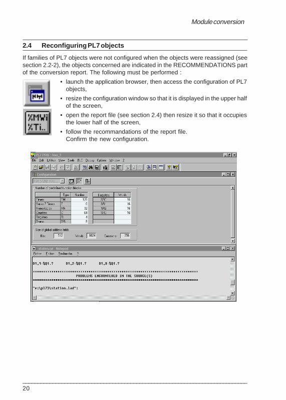
2.4 Reconfiguring PL7 objects
If families of PL7 objects were not configured when the objects were reassigned (seesection 2.2-2), the objects concerned are indicated in the RECOMMENDATIONS partof the conversion report. The following must be performed :
• launch the application browser, then access the configuration of PL7objects,
• resize the configuration window so that it is displayed in the upper halfof the screen,
• open the report file (see section 2.4) then resize it so that it occupiesthe lower half of the screen,
• follow the recommandations of the report file.Confirm the new configuration.

Module conversion
___________________________________________________________________________21
2.5 Importing the converted file into PL7
If the conversion has been interrupted after the creation of the .LD, .ST or .GR7 sourcefile, re-establish the conversion context by opening the .STX file which has been saved.To import the source file into PL7 :
• launch the application browser (Ladder, Structured Text or Grafceteditor), then resize the screen so that it is displayed in the upper halfof the screen,
• open the report file if it is not on the screen (see section 2.3) then resizeit so that it occupies the lower half of the screen,
• follow the recommendations in the report file, that is, initiate the importof the .LD or .GR7 file (File menu, Import command).
• define the tree-structure of the source file to be imported (logical drive, directories,.LD, .ST or .GR7 file name) then start its import with OK.

Module conversion
___________________________________________________________________________22
During the import operation, all the program elements which have been convertedcorrectly are inserted automatically into the selected PL7 module. These programelements (Ladder language rungs, Structured Text statements, or charts) are displayedin black.
If a conversion error occurs, the program elements are incomplete and displayed in red.The recommendations in the conversion report must be followed to update theelements and thus validate them.
Note :Program elements are imported as "discrete" logic and the import stops when it meets anincorrectly converted program element. The error is indicated in a dialog box which enables theuser to either correct or continue the import.

Module conversion
___________________________________________________________________________23
2.6 Correspondence file
The .C73 correspondence file enables a copy (save) to be kept of a source file analysisand the reassignments, so they can be retrieved if need be. This file is thereforeassigned to a PL7-3 source file, whose name it takes by default.
The correspondence file is created systematically during each analysis. It can also becreated by the user from the file analysis screen, using the Save command (see section2.2-2). This displays the following dialog box :
By default the correspondence file takes the same name as the source file, followedby the extension .C73. The file name can be modified, but not its extension (.C73). Thiswill be saved in the same directory as the source file.
Reading a correspondence file enables objects resulting from the analysis of aprogram module (or a module part) to be reassigned, according to the values savedin this save file.The correspondence file is read from the module analysis screen using the Retrievecommand (see section 2.2-2). This displays the following dialog box :

Module conversion
___________________________________________________________________________24

Appendix
___________________________________________________________________________25
3.1 Correspondence between PL7-3 and PL7 objects
The conversion procedure creates, as far as is possible, a table of correspondencebetween PL7-3 objects encountered in the program source on input, and their PL7equivalents. PL7-3 objects can be divided into three categories :
(1) objects which have a PL7 equivalent and which are automatically translated.
(2) objects which have a PL7 equivalent, but which are not automatically translated.This is the case for I/O objects whose correspondences must be defined by the user.It is to be noted that for these PL7-3 objects which do not have any direct equivalent,the user must choose a PL7 object belonging to the same family, except in thefollowing two cases :- bits and words associated with macro-steps are replaced by step bits and words,- PL7-3 remote I/O objects can become local PL7 I/O objects.
(3) objects which exist in PL7-3, but not in PL7 (Text block, Control block, OFB).
NoteSystem bits and words form heterogeneous families of objects and can belong to the threecategories : SY0 becomes %S0, SY11 cannot be replaced by %S11 because these two objectshave different functions, SY12 exists but %S12 does not exist.
The following tables give the correspondence and the possible differences betweenPL7-3 and PL7 objects :
Immediate values
Objects PL7-3 PL7
Base 10 integer 1234 1234
Base 2 integer L'0000000010011110' 2#10011110
Base 16 integer H'ABCD' #ABCD
BCD integer B'1234' #1234
Floating point -1.32e12 -1.32e12
Character string M'aAbBcB' 'aAbBcC'
Labels
Objects PL7-3 PL7
Label L i %Lii = 1 to 999 i = 1 to 999
Section 33 Appendix

Appendix
___________________________________________________________________________26
Bits
Objects PL7-3 PL7
Rack input bit Ixy,i %I<rack_mod>.<channel> (1)Indexed rack input bit Ixy,i (Wj)Remote input bit RIx,y,i %I\<path>\<mod>.<channel> (1)Indexed remote input bit RIx,y,i (Wj)
Rack output bit Oxy,i %Q<rack_mod>.<channel> (1)Indexed rack output bit Oxy,i (Wj)Remote output bit ROx,y,%Q\<path>\<mod>.<chan.>(1)Indexed remote output bit ROx,y,i (Wj)
Rack I/O fault bit• module fault bit Ixy,S / Oxy,S %I<rack_mod>.MOD.ERR• channel fault bit %I<rack_mod>.<channel>.ERR (1)
Remote I/O fault bit• module fault bit %I\<path>\<mod>.MOD.ERR (1)• channel fault bit RDx,y,i / ERRORx,y,i %I\<path>\<mod>.<chan.>.ERR (1)• output channel tripping bit TRIPx,y,i• output channel reset bit RSTx,y,i
Internal bit B i %Mi
Indexed internal bit Bi(Wj) %Mi[%MWj]
System bit S Y i % S i (2)
Step bit X i % X i
Macro-step bit XMj %XMj
Step bit i of macro-step j Xj, i %Xj. i
Input step bit of macro-step j Xj,I %Xj.I
Output step bit of macro-step j Xj ,O %Xj.O
Bit j of internal word i Wi, j %MWi:Xj
Bit j of indexed internal word i Wi(Wk),j %MWi[%MWk]:Xj
Bit j of constant word i CWi,j %KWi:Xj
Bit j of indexed constant word i CWi(Wk),j %KWi[%MWk]:Xj
Bit j of register i I/OWxy,i,j
Bit k of common word j COMi,j,k %NWi.j:Xkof station i COMXi,j,k %NXWi.j:Xk
(where X = B, C, D)
Bit j of system word i SWi, j %SWi:Xj
Note(1) These objects must be reassigned by the user :
path = <rack_module>.<channel>.<connection_point>
(2) When the correspondence between PL7-3 and PL7 objects is not correct, the object %Siappears in red.

Appendix
___________________________________________________________________________27
Words
Objects PL7-3 PL7
Single length internal word W i %MWi
Indexed single length internal word Wi(Wj) %MWi[%MWj]
Double length internal word DWi %MDi
Indexed double length internal word DWi(Wj) %MDi[%MWj]
Real internal word %MFi
Indexed real internal word %MFi[%MWj]
Single length constant word CWi %KWi
Indexed single length constant word CWi(Wj) %KWi[%MWj]
Double length constant word CDWi %KDi
Indexed double length constant word CDWi(Wj) %KDi[%MWj]
Real constant word %KFi
Indexed real constant word %KFi[%MWj]
Single length input register word IWxy,i %IW<rack_mod>.<channel> (1)
Double length input register word %ID<rack_mod>.<channel> (1)
Single length output register word OWxy,i %QW<rack_mod>.<channel> (1)
Double length output register word %QD<rack_mod>.<channel> (1)
Remote input register word RIWx,y,i %IW\<path>\<mod>.<channel>
Remote output register word ROWx,y,i %QW\<path>\<mod>.<channel>
System word S W i %SWi (2)
Common word j of station i COMi,j %NW{i} j (1)COMXi,j (where X = B, C, D) %NW{[r.]i}j
r = network number
Status word of a remote discrete module STATUSAx,y,iSTATUSBx,y,i
Status word of a remote disc.module channel STSx,y,i
Activity time of Grafcet steps Xi,V %Xi.T
Activity time of step i of macro-step j Xj,i,V %Xj.i.T
Activity time of input step of macro-step j Xj,I,V %Xj.IN.T
Activity time of output step Xj,O,V Xj.OUT.Tof macro-step j
Note(1) These objects must be reassigned by the user :
path = <rack_module>.<channel>.<connection_point>
(2) When the correspondence between PL7-3 and PL7 objects is not correct, the object %Siappears in red.

Appendix
___________________________________________________________________________28
Function blocks
Objects PL7-3 PL7
Timer T i %Ti• preset value word Ti,P %Ti.P• current value word Ti,V %Ti.V• timer running bit Ti,R %Ti.R• timer done bit Ti,D %Ti.D
Monostable Mi %MNi• preset value word Mi,P %MNi.P• current value word Mi,V %MNi.V• monostable running bit Mi,R %MNi.R
Up/down counter C i %Ci• preset value word Ci,P %Ci.P• current value word Ci,V %Ci.V• upcount overflow bit Ci,E %Ci.E• preset bit reached Ci,D %Ci.D• downcount underflow bit Ci,F %Ci.F
Register R i %Ri• input word Ri,I %Ri.I• output word Ri,O %Ri.O• register bit full Ri,F %Ri.F• register bit empty Ri,E %Ri.E
Drum controller %DRi
Text TXTi• table length word in bytes TXTi,L• status word TXTi,S• module address word and channel no. TXTi,M• request code word TXTi,C• TELWAY station address word TXTi,A• communication text block no. word TXTi,T• exchange report word TXTi,R• exchange over bit TXTi,D• incorrect exchange bit TXTi,E
Control CTRLi• activated task bit CTRLi,R

Appendix
___________________________________________________________________________29
Bit and word tables
Objects PL7-3 PL7
Bit strings• internal bit string Bi[L] %Mi:L• input bit string Ixy,i[L] %Ixy.i:L• output bit string Oxy.i[L] %Qxy.i:L• Grafcet step bit string Xi[L] %Xi:L• macro-step bit string XMi[L]
Character strings %MBi:L (1)(with i even)
Word tables• table of internal words Wi[L] %MWi:L• table of indexed internal words Wi(Wj)[L] %MWi[%MWj]:L• table of double internal words DWi[L] %MDi:L• table of double indexed internal words DWi(Wj)[L] %MDi[%MWj]:L• table of constant words CWi[L] %KWi:L• table of indexed constant words CWi(Wj)[L] %KWi[%MWj]:L• table of double constant words CDWi[L] %KDi:L• table of indexed double constant words CDWi(Wj)[L] %KDi[%MWj]:L• table of reals %MFi:L• table of indexed reals %MFi[%MWj]:L• table of constant reals %KFi:L• table of indexed constant reals %KFi[%MWj]:L• table of remote input elements RIx,y,i[L]• table of remote output elements ROx,y,i[L]• table of indexed remote input elements RIx,y,i(Wj)[L]• table of indexed remote output elements ROx,y,i(Wj)[L]
Optional function blocks
Objects PL7-3 PL7
Optional function block <OFB>i
OFB element <OFB>i, <element> (2)
Indexed OFB element <OFB>i,<element>(Wj) (2)
Table of OFB elements <OFB>i,<element>[L] (2)
Table of indexed OFB elements <OFB>i,<element>(Wj)[L] (2)
Note(1) In PL7, a character string is a series of adjacent bytes of the same type.
(2) <element> can be a bit, a word or a double word.

Appendix
___________________________________________________________________________30
Instructions
Objects PL7-3 PL7
Instructions on bits• Logical inversion NOT NOT• AND • AND• OR + O R• Exclusive OR X O R• Rising edge R E R E• Falling edge F E F E• Set to 1 S E T S E T• Reset RESET RESET
Instructions on words and double words• Addition + +• Subtraction - -• Multiplication * *• Division / /• Comparisons >, >=, <, <=, =, <> >, >=, <, <=, =, <>• Remainder of a division REM REM• Square root SQRT SQRT• Absolute value A B S• Logic AND AND AND• Logic OR O R O R• Exclusive logic OR X O R X O R• Logic complement CPL NOT• Incrementation INC INC• Decrementation DEC DEC• Logic shift to the left SHL SHL• Logic shift to the right SHR SHR• Circular shift to the left SLC ROL• Circular shift to the right SRC ROR
Floating point type instructions (1)• Addition ADDF +• Subtraction SUBF -• Multiplication MULF *• Division DIVF /• Square root SQRTF SQRT• Absolute value A B S• Equality test EQUF =• Strict superiority test SUPF >• Strict inferiority test INFF <• Other tests >=, <=, <>
Note(1) Floating point objects do not exist in PL7-3. These instructions handle PL7-3 objects of the
following types : internal double word (DWi), constant double word (CDWi) or OFB extractdouble word.

Appendix
___________________________________________________________________________31
Instructions (cont'd)
Objects PL7-3 PL7
Instructions on byte strings• Circular shift SLCWORD
Conversion instructions• BCD binary conversion DTB BCD_TO_INT• Binary BCD conversion BTD INT_TO_BCD• ASCII binary conversion A T B STRING_TO_INT or
STRING_TO_DINT• Binary ASCII conversion B T A INT_TO_STRING or
DINT_TO_STRING• Gray binary conversion GTB GRAY_TO_INT• Floating point integer conversion FTB REAL_TO_INT or
REAL_TO_DINT• Integer floating point conversion FTF INT_TO_REAL or
DINT_TO_REAL• BCD floating point conversion DTF BCD_TO_REAL• Floating point BCD conversion FTD REAL_TO_BCD• ASCII floating point conversion ATF STRING_TO_REAL• Floating point ASCII conversion FTA REAL_TO_STRING
Instructions on tables• Arithmetic operations +, -, *, /, REM +, -, *, /, REM• Logic operations AND, OR, XOR AND, OR, XOR, NOT• Addition of words in a table + SUM• Search for the 1st different word EQUAL EQUAL• Search for the 1st equal word SEARCH FIND_EQU
Instructions on program• Jump JUMP Li JUMP %Li• Call subroutine CALL SRi SR i• Subroutine return RET RETURN• Halt the application HALT HALT• Conditional statement IF / THEN / ELSE IF / THEN /ELSE /END_IF• Iterative statement WHILE / DO WHILE / DO / END_WHILE
Instructions on interrupts• Test READINT• Mask MASKINT MASKEVT• Unmask DMASKINT UNMASKEVT• Acknowledge ACKINT• Generate an IT to the module SETIT
Explicit I/O instructions• Read discrete inputs READBIT• Write discrete outputs WRITEBIT• Read registers READREG• Write registers WRITEREG• Read words READEXT• Write words WRITEEXT

Appendix
___________________________________________________________________________32
Instructions (cont'd)
Objects PL7-3 PL7
Instructions on function blocks• Preset PRESET Ti / Ci PRESET %Ti / %Ci• Start START Ti / Mi START %Ti / %MNi• Activate the task START CTRLi• Reset RESET Ci / Ri / TXTi RESET %Ci / %Ri• Deactivate the task RESET CTRLi• Upcount UP Ci UP %Ci• Downcount DOWN Ci DOWN %Ci• Store in a register PUT Ri PUT %Ri• Retrieve from a register GET Ri GET %Ri• Receive a message INPUT TXTi• Send a message OUTPUT TXTi• Send/Receive a message EXCHG TXTi• Execute an OFB EXEC <OFBi>• Read telegrams READTLG

Appendix
___________________________________________________________________________33
3.2 Differences between PL7-3 and PL7
1 Application structure
A PL7-3 application comprises a maximum of 7 tasks (MAST, FAST, AUX0 to AUX3 andan interrupt task), whereas a PL7 application comprises :
• 2 tasks (MAST and FAST) plus event processing
2 Ladder Language
• Order of evaluation of Ladder language rungsIn PL7-3, evaluation is performed from left to right , column by column and from topto bottom of each column. In PL7, it is performed rung by rung and in the directionof the equation for each rung. Although they are converted in an identical graphicform, some Ladder language rungs can be evaluated differently (give a differentresult on execution). These Ladder language rungs contain an object which issimultaneously evaluated and updated (using a coil or a function block).
Updating performed by a coil- with PL7-3, the B2 contact (%M2) was evaluated before coil B2 (%M2),- with PL7, coil %M2 is updated before contact %M2 is evaluated.
Updating performed by a function block- with PL7-3, timer T1 (%T1) was called before contact T1,R (%T1.R) was evaluated,- with PL7, contact %T1.R is evaluated before timer %T1 is called.
Note : these different evaluations are not detected by the converter.
%M0 %M2
%M2 %M4
%M0 %M2
%M2 %M4
%T1.R %M2 %T1.R %M2
%M4%M0
%M1
%T1E
C
D
R
%M0
%M1
%T1E
C
D
R

Appendix
___________________________________________________________________________34
• JUMP coilIn PL7-3, the JUMP coil is symbolized by -(J)- and supports a connecting label. In PL7,its new symbol is -->> %Li. It still enables jumps to a labelled rung in the sameprogramming entity.
• OPERATE blocksOPERATE blocks, containing the instructions HALT or RET in PL7-3, are replacedin PL7 by special coils (--<HALT>- and -<RETURN>-).
• Comment attached to a Ladder language rungIn PL7 a comment attached to a Ladder language rung does not reduce the size ofthe entry zone. This remains as 7 lines of 11 columns, unlike PL7-3 where there areonly 6 lines.
• Nesting rungsDue to the different evaluation logic,some Ladder language rungs allowedin PL7-3 are not permitted in PL7. Sincethe converter does not take into accountthe automatic reorganization of suchLadder language rungs, the user mustperform the necessary modifications toeliminate nesting.
3 Grafcet language
• Structure of a pageThe structure of the Grafcet page differs between PL7-3 and PL7 :
- the number of columns changes from 8 in PL7-3 to 11 in PL7. However the verticalpage structure remains the same (alternating between 6 lines of steps and 6 linesof transitions).
- there are no longer distinct fields for charts and comments (this is the reason for theincrease in the number of columns). In PL7, comments can be entered in any cellon the page. However for reasons of similarity, comments from a PL7-3 module areplaced by the converter from the ninth column onwards in PL7. The maximum sizefor a comment has been increased by 4 characters, thus changing from 60 to 64characters. In fact, PL7 syntax requires that a comment be surrounded by characterstrings (* and *).
%T1.R %M0
%T1E
C
D
R
%M1%T1.D
STOP

Appendix
___________________________________________________________________________35
• Transition conditionsIn PL7-3, an empty transition condition (ie unprogrammed) is considered as alwaysbeing true : the transition is cleared as soon as it is validated.
In PL7, an empty transition condition acts as a block, ie it is always false. For it to becleared a Ladder or Structured Text program containing a single # coil must beassigned to it. The role of this coil is to force movement to the following step.
4 Structured Text language
• AssignmentIn PL7-3, assignment (or multiple assignment) is defined by the instruction -> :<sou rce> -> < ta rge t> or in the case of multiple assignment<source> -> <targ1> -> ... -> <targn>
In PL7, the assignment instruction becomes := and the assignment direction changes :< ta rge t> := <sou rce> or in the case of multiple assignment<targn> := ... := <targ1> := <source>
• CommentIn PL7-3, the comment is associated with each Structured Text statement and is thefirst line of this statement. It contains a maximum of 78 characters.
In PL7, the comment is restricted by delimiters(* and *) and can take up severallines anywhere in the statement. It can be up to 256 characters.
• ComparisonIn PL7-3, comparisons are written in square brackets, whereas in PL7 they are writtenin rounded brackets (which are not compulsory) :[<expr1> <oper> <expr2>] in PL7-3(<expr1> <oper> <expr2>) or <expr1> <oper> <expr2> in PL7
<oper> : < / > / <= / >= / = / <>
• Boolean operatorsIn PL7-3, the arithmetic symbols * and + are used to write the logic AND and the logicOR. In PL7, the logic AND becomes AND and the logic OR becomes OR.Moreover in PL7-3, the exclusive OR (XOR) has a lower priority than the logic OR,whereas the opposite is true in PL7 : XOR has a higher priority than OR.
• TerminatorsIn PL7-3, the instructions IF, WHILE, REPEAT and FOR have no terminator. Howeverin PL7 a terminator is compulsory :- IF ends with END_IF,- WHILE ends with END_WHILE,- REPEAT ends with END_REPEAT, and- FOR ends with END_FOR.
Appendix
___________________________________________________________________________36
• Calling a subroutine SRiIn PL7-3, a subroutine is called by writing CALL SRi. In PL7, "CALL" disappears andthis instruction becomes SRi.
• Separators for instruction parametersIn PL7-3, instruction parameters are separated by semi-colons (;), while in PL7, theseparator is the comma (,).
• Instructions on ITPL7-3 instruction on interrupts (READINT, MASKINT, DMASKINT, ACKINT andSETINT) do not exist in PL7 : system bits are used to program interrupts.
• Text blockThe text block (TXT), used in PL7-3, no longer exists in PL7.
• Explicit I/O instructionsPL7-3 explicit I/O instructions (READBIT, WRITEBIT, READREG, WRITEREG,READEXT et WRITEEXT) no longer exist in PL7.
• Operations on floating point objectsThe PL7-3 instructions : ADDF, SUBF, MULF and DIVF no longer exist in PL7. In thislanguage, operations on floating point objects use the usual arithmetic symbols (+,-, * and /).
• Action separatorsThe semi-colon (;) is used to separate actions in both PL7-3 and PL7. However, it isused much more frequently in PL7 : all actions are followed by an ";" which is aterminator character. Even a single action is ended with a semi-colon.
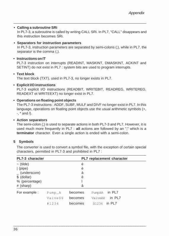
5 Symbols
The converter is used to convert a symbol file, with the exception of certain specialcharacters, permitted in PL7-3 and prohibited in PL7 :
PL7-3 character PL7 replacement character
~ (tilde) é| (pipe) è_ (underscore) à$ (dollar) ê% (percentage) î# (sharp) â
For example : Pump_A becomes PumpàA in PL7
Valve$$ becomes Valveêê in PL7
#1234 becomes â1234 in PL7

Index
___________________________________________________________________________37
INDEXPL7-3 application converter
Symboles.C73 4, 23.CST 3, 10.GR7 3, 10.LAD 3.LD 3, 10.LIT 3, 10.RPT 4.SCY 3, 4, 10.ST 3, 10.STX file 6<< and >> characters 14
AAccessing the report file 19Action separaters 36Add program 10Add programs key 11Analyze 11, 13Application browser 21Application structure 33Assignment 35
BBinary file 3Bit and word tables 29Bit strings 29Bits 26Bits and system words 25Black 13Boolean operators 35
CCalling a subroutine SRi 36Character strings 29Choosing the modules 9Commands 16Comment 3, 34, 35Comment attached to a rung 34Comparison 35Complete the program elements 5Configured 14Constants 3, 10
Constants file 3Constants module 9Contents of a Grafcet step 3Conversion instructions 31Conversion of the module 16Conversion option 12Conversion procedure 7Conversion report 17Convert key 16Convert/PL7-3 application command 9Convert/PL73 converter 9CORRECT 14Correspondence 16Correspondence between objects 25Correspondence file 4, 23Correspondence table 25
DDelete modules 11Directory column 10Displaying the report 19
EEvaluation of Ladder language rungs 33Explicit I/O instructions 31, 36
FFile/Convert command 7File/Import 21File/New command 6, 9File/Open command 6, 9Floating point type instructions 30From 15From page 12From rung 12From statement 12Function blocks 28
GGrafcet 10Grafcet pages 3Gray 14Green background 14

38___________________________________________________________________________
IImmediate values 25Import command 21Import program elements 22Import the source 5Importing 21Indexed constant word 3Indexed word 3Instructions 30Instructions on bits 30Instructions on byte strings 31Instructions on function blocks 32Instructions on interrupts 31Instructions on IT 36Instructions on program 31Instructions on tables 31Instructions on words and double words 30
JJUMP coil 34
LLabels 25Ladder 10List of selected modules 10Literal 10
MModify configuration 5Modify part 11, 12Modular conversion 3, 4Modular save 5Module selection screen 11Module selection window 11Modules to be converted 9Multiple selection 11
NNesting rungs 34NO OBJECT 14Non symbol 3NOT ASSIGNED 14
NOT CONFIGURED 15NOT CONVERTIBLE 15Notepad 19Number of objects 15Number of objects counter 15Number of objects field 15
OObject family 13Object offered 15OPERATE blocks 34Operations on floating point objects 36Optional function blocks 29Options / Customize menu 10
PPart column 12Part field 10PL7 target 10PL7 target file column 10PL7-3 modules 10PL7-3 source module column 10Principle of conversion 4Program module 3, 9, 11Program source file 3Proposals 15Proposals field 15
QQuit 16
RReassign 15Reassignment of objects 13RECOMMENDATIONS 20Recommendations 18Reconfiguration 20Red 14Red background 14, 15Rename Target 11Report file 4, 17Result of the conversion 17Retrieve command 16, 23Retrieve key 16

Index
___________________________________________________________________________39
SSave 16, 23Save command 23SCY 3Select binary 10Select constants 10Select modules key 16Select symbols 10Selected modules 10Selecting the program module 11Separators for instruction parameters 36Separators for parameters 36Source 14Source file 3Source module 3Source zone 14Structure of a page 34Structured Text 10, 17Symbols 3, 10, 11, 36Symbols file 3Symbols module 9Symbols source file 3
TTarget 14Target directory 10Target file 10Task organization 5Terminator 36Text block 36To 15To page 12To rung 12To statement 12Transition conditions 35
UUpdating by a coil 33Updating by a function block 33Usage for family 14Used 14
WWord table 29Words 27

40___________________________________________________________________________