piw collection
TRANSCRIPT

PAPER INDUSTRY WEB
Avandetq

ContentI.Introduction to Winding
II.Inertia in Winding
III.Wound Roll Structure
IV.Wound Roll Testing
V.TNT-Tools of Winding
VI.Cameron Gap Test
VII.Winding Scrap Book
VIII.Reel
IX.Building a Core Loading Cart

I.Introduction to WindingPURPOSE OF THE PAPER MACHINE WINDER
The paper comes off the paper machine in very large rolls called jumbo rolls or reels The jumbo is the width of the paper machine ranging nominally from 100" to 360" {2540 to 9140 mm} wide. The jumbo roll is wound on a shaft called a reel spool. The reel spool diameter and weight is proportionate to the width of the paper machine and the weight of the jumbo. It is not unusual to see reel spools 30"to 36" diameter {762 to 914 mm} and jumbo reels greater than 100"{2540 mm} diameter. On large paper machines jumbo rolls can weigh in excess of 35 tons {31.7 metric tons}.
The purpose of the machine winder is to convert the large jumbo roll into sizes convenient to ship. The size of the "shipping roll" will be determined by the end use, generally referred to as the converting process. Examples of some of the converting end uses are printing presses, corrugating machines, bag machines sheeters etc.

I.Introduction to WindingTHE TWO BASIC WINDER TYPES.
The most popular type paper machine winder is known as a two drum winder. The two drum winder winds the rolls on a single axis, all the rolls being wound on a common center, adjacent to each other across the width of the winder. Papers wound on a two drum winder are standard newsprint, fine papers such as tablet or copy papers, board grades, tissues, and towel-to name a few. Normally, only a single two drum winder is required to handle the paper machine production.
A second popular type paper machine winder is known as a duplex winder, used to wind papers that are considered difficult to wind, that is: To structure the shipping rolls in a manner that the defects in the roll will be reduced. Papers wound on a duplex winder are generally coated papers such as magazine stock, high gloss specialty papers, enhanced newsprint, etc. These are papers that are filled with coating materials and processed in an additional finishing operation to make the surface extremely smooth and glossy. In looking at a it will be noted that unlike a two drum winder, each individual roll is supported and wound at separate winding stations located on opposite sides of a center drum across the full winder width.

I.Introduction to Winding

I.Introduction to Winding

I.Introduction to WindingIt is important to recognize the dynamics of a paper machine winding process. The
equipment used is massive and subject to abuse through hard use. The winder differs significantly in operation from the paper machine. The paper machine is a continuos operation. On the other hand, the winder is considered a batch operation. The process is stopped on a routine basis to load new jumbo rolls in the unwind and to eject finished sets out of the winder. Because the winder is a batch operation, it must operate at a higher speed than the paper machine to stay ahead of the paper machine production. Winder speeds are generally 2 to 2 1/2 times faster than the paper machine.
To satisfy the production requirements of the paper machines, winders, in addition to their inherent high operating speed, must cycle massive components rapidly to reduce down time. Most winding functions are automated both from a mechanical and control standpoint. To appreciate the dynamics of a winder operation, consider the weight of the jumbo roll in the unwind. The jumbo can weight in excess of 40 tons {36.3 metric tons}.
When winding at high speeds it is not uncommon to observe the jumbo roll from the machine reel accelerate from 0 speed to 7500 FPM (85 MPH) {2286 MPM (137 KM/HOUR)}in 1 to 2 minutes, run at a steady state and then decelerate to a stop in 1 to 2 minutes. All this must be done in very strict control to produce uniform roll structure and minimize lost time by sheet breaks in the winder. This cycle can be repeated 160 times per day on a high speed newsprint paper machine processing 40" {1016 mm} diameter rolls at 4000 FPM {1219 MPM}.

I.Introduction to Winding

I.Introduction to WindingWINDER COMPONENTS
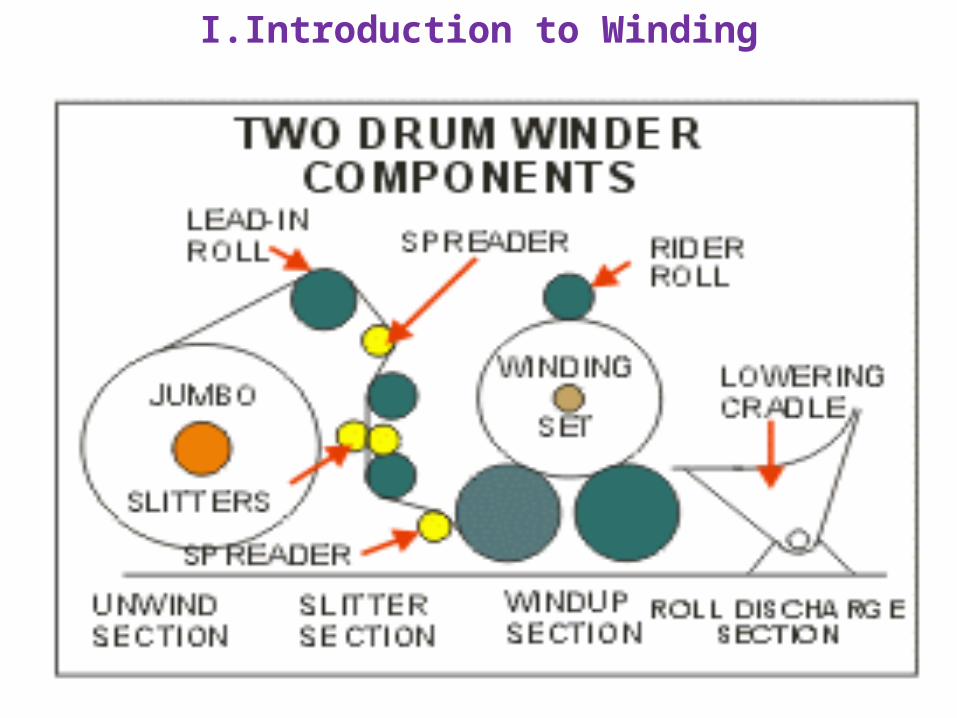
There are numerous components in a high speed paper machine winder. Each type winder consists of five basic sections and a large number of lesser size components. The slitter section includes the slitters required to cut the jumbo roll to various widths and trim the front and back edges of the jumbo roll. There can be almost any number of slitters across the width of the winder as well as several versions of mechanical and automatic slitter arrangements. Slitters can number anywhere from 3 or 4 up to 20 or more on a single winder. The slitter section also includes the lead in roll, various rotating rolls to support the sheet during the winding process. as well as the before slitter spreading device.
The windup section (or drum section) includes an additional spreading device, a wound roll ejector, the winder drums that support the winding rolls (called a set) during winding, the necessary heavy framework to support the various other components such as the rider roll, the core chucks, and their associated parts.
I.Introduction to Winding
I.Introduction to WindingThe two drum winder and duplex winders have variations of the same
components and are arranged differently to accommodate the winding principles. Depending on the winder builder, the slitter section can be an overhead configuration or arranged below the floor in the basement. Various arrangements can have both before and after spreader rolls or a single spreader located before the slitters. In the case of the two drum winder, one winder will generally be sufficient to handle a single paper machine.
The duplex winder, by it's very nature, is less efficient from a production standpoint than a two drum winder. In most cases, on grades where a duplex winder is required there will be two duplex winders following the paper machine.

I.Introduction to Winding

I.Introduction to WindingTHE UNWIND SECTION
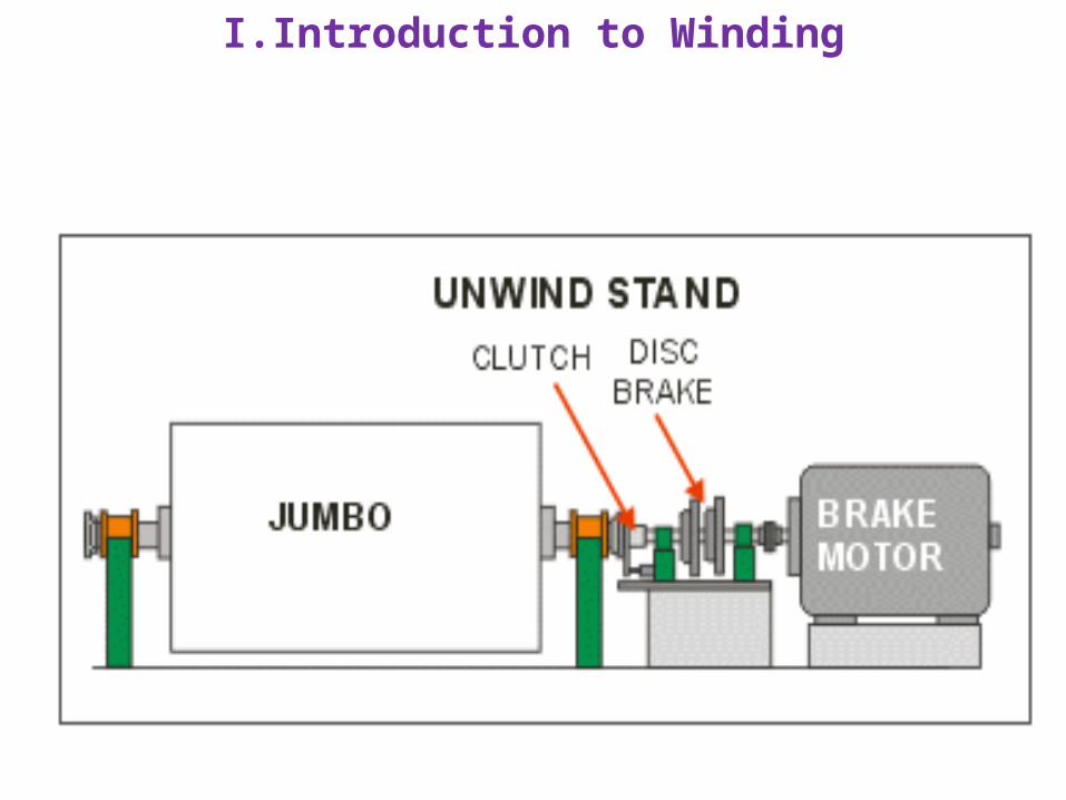
The unwind section consists of a pair of heavy stands that support the jumbo roll during the unwinding process. A braking mechanism is located at the drive side (back side) of the unwind stand. The brake can be a mechanical unit, a regenerative electric motor or a combination of the two depending on the duty of the winder.
A simple mechanical brake is used to control the tension in the sheet during winding. The pure mechanical brake does not provide inertia compensation for the heavy mass of the jumbo roll unwinding in the unwind stand. Control of the unwinding process is by the brake holding back on the sheet during unwinding and regulation of the accel/decel rates. This arrangement is cost effective for a simple winding operation. A pure mechanical unwind brake is popular on heavier weight papers such as liner board and pulp.
I.Introduction to Winding

I.Introduction to WindingA popular arrangement on lighter weight sheets when accurate tension
control and inertia compensation of the unwind jumbo roll is required is an electric motor configured as a regenerative brake. The regenerative brake has the ability to "motor" the sheet through the winder, permitting higher acceleration rates than a mechanical brake and quicker deceleration rates due to the inertia compensation for the jumbo roll.
A third arrangement, is a combination mechanical/regenerative brake. This arrangement has a couple benefits over either of the above, particularly when higher than normal amounts of HP are required. Very large regenerative brake motors are costly. The high cost of a single large motor can be minimized by using two half size motors coupled in tandem. The cost of spares is somewhat reduced also. Some mills prefer to use a half size motor and couple it to a mechanical brake. It has an advantage of a "back-up mechanical brake at reduced speed if the electric motor requires maintenance.
Depending on productivity or available space the unwind section may also include extended jumbo roll storage rails, jumbo roll injector, empty reel spool ejector and overhead reel spool storage rails.

I.Introduction to WindingWOUND ROLL DISCHARGE SECTION
Every winder must have a means to handle the rolls out of the winder. The discharge section generally includes a winder bridge or gate to deliver the wound roll set to a cradle for lowering the rolls to floor level. Most modern winders use a cradle that includes an integral bridge. After the rolls are discharged from the winder, operators plug and label the individual rolls of the set and dispatch them to a roll wrapper for shipment or storage.

I.Introduction to Winding

I.Introduction to WindingELECTRIC DRIVE SECTION
The electric drive section consists of various electric drive motors for the unwind, slitter, and windup section including drives for paper rolls, rider roll and other rotating elements as needed. The electric drive control hardware and software is included in the drive vendor package and normally installed in a temperature controlled environment. A typical electric drive for a two drum winder will consist of an unwind breaking arrangement using any of the brake arrangements described earlier, to provide sheet tension and inertia compensation of the large jumbo roll. Separate motors are connected to each winder drum. The winder drum drives are configured to provide differential torque (or speed) to the drums to assist in optimizing wound roll structure. There are individual drive motors on paper carrying rolls and spreader rolls as required to reduce friction transients imposed by the inertia of the rolls during acceleration and deceleration There are also fractional motors used for slitters and other winder functions as required.
The basic duplex winder electric drive is similar in many respects to the two drum with the exception of a single drum drive The individual winding positions of a duplex winder require an additional drive and control level to accommodate the center torque of the individual winding stations although some manufacturers may not use centerwind drives.

I.Introduction to Winding

I.Introduction to WindingMISCELLANEOUS COMPONENTS
There are a host of other components associated with the winder including the main operator control station, core loading equipment, empty spool removers hydraulic systems, trim systems and other specialized systems to suit individual installations.
It should be noted, for clarification that two drum winders are used in varying configurations. The slitter sections can be arranged in either a vertical or horizontal arrangement. There are two drum winders that use compliant drums, belted drums, non level drums, inclined ways, three winder drums, etc. Then there are variations of these winders used as reclaim or reprocessing in off machine utility.
Similarly, duplex winders are manufactured in many configurations. Two major groups are the core support and drum support versions. There is also a breakdown in the nip and centerwind configurations. Regardless of the multiple arrangements and configurations, most winders can be sorted in the two classic groups-two drum or duplex. The slitters can be above or below the floor line.

II. Inertia in WindingIn the scheme of things, the winder is a VERY small part of the overall
picture. In a greenfield mill, the winder probably represents about one half of one percent of the total project investment but has a VERY dramatic effect on the finished product out the door.
DYNAMICS have a great impact in the winder operation and how it effects the winder's ability to keep production parity with paper machine production.
Regardless if the the winder follows a newsprint machine operating at 4000 FPM or a 69# linerboard machine operating at 1750 FPM, the job is nearly impossible in a 24 hour-7 day a week duty cycle. The winder duty is difficult on either end of the production spectrum-light or heavy weights.

II. Inertia in Winding

II. Inertia in Winding69# LINERBOARD/1750 FPM MACHINE SPEED
This chart shows a production analysis of a 69# linerboard machine operating at 1750 FPM making a 4 set, 50" diameter jumbo. Under these operating conditions the machine will produce 1883 tons of board in 24 hours, making 291 sets off the winder. Not an easy operating condition for a single two drum winder.

II. Inertia in Winding30# NEWSPRINT/4000 FPM PAPER MACHINE SPEED
Looking at the same kind of analysis for a newsprint machine operating at 4000 FPM, producing 30#/3000 sq. ft. news, making 42" diameter 5 set jumbo, using a 30" diameter reel spool with a single two drum winder.

II. Inertia in WindingTHE JUMBO-IS IT BIGGER THAN LIFE?
The jumbo being produced on our newsprint machine is HUGH. There is no other way to describe it! Just resting on the floor, Magic Johnson could barely reach the top of the reel. (Let him try to make a jump shot with this one!) If you parked your Cadillac Coupe de Ville along side the jumbo, it would still take another one to span the length of the jumbo and spool. (you could buy a Coupe de Ville with a couple of these babies).

II. Inertia in WindingNow to really appreciate what we're up against! The combined weight of the
paper and reel spool that supports the jumbo is equivalent to about 21 Chevy Blazer utility cars. Just think of the inertia when this mass is rotating at high speed in the winder unwind stand: Or think about the horse power it takes to start and stop this mass. The regenerative motor and braking system at the back of the unwind in some cases appears to be almost as large as the jumbo itself. (and Don -"Big Daddy" Garalitus doesn't get off the line much faster).

II. Inertia in WindingCONVERTING THE JUMBOS AT THE WINDER
Our newsprint winder, in a normal day will process over 29 of these big monsters-an average of one every 49 minutes. That includes the bad reels (contrary to what the papermakers may say), winder breaks, drum splices, cores that don't match and the need for , unscheduled maintenance. For openers-this is the scenario if things are going smoothly.

II. Inertia in WindingThe business of the winder (beside having to produce high quality shipping
rolls) is to cut down that enormous jumbo into package sizes convenient to ship and as specified by the printer. This can be anything from a range of 36" to 50" diameter, at varying widths. The more sets we can wind off a jumbo, the better the efficiency of the winder. A practical jumbo size when winding 42" shipping rolls is a 5 set reel about 8 feet in diameter.

II. Inertia in WindingAfter all's said and done, our winder will produce a LOT of shipping rolls in
24 hours. Each of the jumbos will be converted to 5 sets of rolls off the winder, each set slit into six individual rolls weighing about a ton each. We will send 876 rolls to the roll wrapper and the shipping and receiving department. Not a bad days work.

II. Inertia in WindingPAPER MACHINE Vs. WINDER DUTY CYCLE
The paper machine operates at a constant speed 24 hours a day unless there is a sheet break. Comparing the paper machine duty cycle chart in the graphic above, to the batch operation of the winder in the graphic below, the differences in duty cycles are apparent.

II. Inertia in WindingHere's why! This chart shows a typical winder cycle for each of the 29.2
jumbos coming to the winder. It takes 4 minutes to load and thread the winder, 7 minutes to wind each set, and 45 seconds to make a set change. The time for splicing and slitter resetting is averaged in the times. This chart shows that at 7000 FPM, (the speed the winder must average to stay up with the machine at 4000 FPM), there will be 4 minutes between reels providing there are no unexpected events like serious unplanned maintenance, running out of cores, paper machine breaks, etc. It's obvious the crew has to maintain a steady rhythm to keep up.

II. Inertia in WindingTHE MAGICIAN DOES HIS ROPE TRICKS
To get a better understanding of the balanced operation required of the winder, think back to the day you tried to tow a car down the street. How many times did you drive over a slack tow rope or snap it off? Unless the tow car and car being towed kept careful good control it was-to say the very least-a rough ride. This is exactly the same condition at the winder operation-visualize the winder towing the jumbo.
We're trying to pull paper off a 29 ton jumbo with a very thin, fragile tow rope (a .003" inch thick sheet of paper) and do it at speeds to 80 MPH. Our unwind has a regenerative brake motor or combination motor and mechanical brake that accelerates the jumbo until it arrives at speed. If the jumbo tends to over-speed due to rotational inertia, the control system makes adjustments. The tension of the rope is constantly monitored by a control system.

II. Inertia in Winding

II. Inertia in WindingAgain to emphasize what is demanded of the winder, try this one. Get
your neighborhood tow service to make a tow of 3 buses (hitch load 35 tons) with a 450# test tow line from 0 to 80 MPH in 1.5 minutes. Don't be surprised if he can't do it, (or what his tow charge for the road call might be).

II. Inertia in WindingTRUCKIN' ON DOWN

II. Inertia in WindingOne of the best comparisons of the duty cycle of a winder is that of a tractor
trailer. We all, at one time or another, have been passed by a large tractor trailer barreling down the Interstate. Think of the abuse that truck takes, traveling the highways, day and night. If you think that's bad-consider this scenario.
Just imagine you are a tractor trailer driver and have to do the same duty cycle as our newsprint winder. You load up a set of rolls in a mill in New England in 45 seconds. Immediately take off and accelerate the tractor to 80 MPH in 1.5 minutes. Drive at a constant 80 MPH speed for 4 minutes. Slam on the brakes to decelerate to a full stop in 1.3 minutes. Now jump off the cab, unload the set of rolls and load on another set in 45 seconds and away you go again. Further, do this with out damage to the cargo and in a safe manner so no one is injured. Do this 146 times and you'll find yourself in Brunswick, GA, 24 hours and 1,360 miles later. During this 24 hour trip you are only allowed a total of 2 hours for fuel and service, stop for meals or make emergency repairs.
When you arrive at Brunswick, GA, you better have your relief driver and helper ready because you're not staying! You have to turn around and head right back to Maine. The paper machine doesn't stop kicking out rolls and the southbound truck is just leaving, headed our way. Now that's what you call tough duty! (and all the time you are doing this, you better keep an eye peeled for bears taking pictures)
II. Inertia in WindingThe Bottom Line
It is obvious after reviewing the paper machine and winder processes illustrated, that a single two drum winder can be hard pressed to stay up with machine production. The productivity in this article is based on normal operating conditions. It does not take much to go wrong to get the winder behind. There are instances when making newsprint, 2 two drum winders are required. When considering machines producing LWC (light weight coated) grades, normal operation is to use 2 duplex winders.

III. Wound Roll StructurePRIMARY FUNCTION OF A WINDER
Whatever a winder must do, the most important is to produce good salable shipping rolls. Roll structure is probably a good starting point to understand what a winder is, what it does and how it functions. First, keep in mind, every roll that is wound on a winder and shipped to an end user will be supported on it's core to be unwound. The projected support area of a core is relatively small when compared to the weight of the roll. An understanding of roll structure is necessary to appreciate why this is important.
III. Wound Roll StructureSHIPPING ROLL REQUIREMENTS
Shipping roll requirements vary greatly. The critical grades are printing papers: News, supered news, lightweight coated grades such as roto and offset papers and many specialty papers. In the most basic definition an acceptable shipping roll must be hard enough at the core to support itself during unwinding, just hard enough at the OD to be handled and shipped without damage and a smooth transition in wound in tension (or hardness) from the core to the OD. This simple definition can be embellished with all sorts of requirements such as straight sided, uniform cross machine hardness, number of splices, annular rings, etc. For now, let's stick with this simple description of a good shipping roll.

III. Wound Roll StructureUNWINDING A SHIPPING ROLL
When a roll is supported on it's core to be unwound, the complete weight of the roll is supported on the projected area of the core. Reducing the pressure to zero on the bottom side of the core will cause the paper to loose grip on the core. An internal gear effect occurs as the core and the roll rotates, in this case the core being the pinion of the internal gear.

III. Wound Roll StructureWhen the roll is unwound, chucks are inserted in the ends of the core to
support the roll and braking is applied at the core or surface depending on the converting machinery. This provides tension in the sheet so it may be controlled in the converting process. As the roll is unwound, the core is held back but the roll tends to rotate freely due to inertia. This causes an internal gearing effect between the core and the roll body (the paper on the core). This internal gearing causes layer to layer slippage within the roll generally starting down near the core and working outward. The amount of internal gearing is Dependent on many factors. The structure of the roll and surface of the sheet are the biggest contributing factor.

III. Wound Roll Structure

III. Wound Roll StructureIf you would like to try the "core move test" all you need is a roll of
toilet tissue. Scribe straight lines on one of the roll faces with a magic marker. Place the roll on a surface such as a table or desk with the core parallel to the surface. Rest your hand firmly on top of the roll and roll your test roll away from you. The scribed lines should deform as in the diagram. The effect can be reversed by rotating the roll back towards you until the lines return to the original shape. Continuing rolling the test roll towards you will reverse the deformation in the opposite direction.
The interesting part of this test is that using different brands of toilet tissue will produce varying patterns of deformation depending on the tightness of the roll and the coefficient of friction of the paper. Some brands and tissues with embossing may not deform very much if at all due to a significantly higher coefficient of friction. Factors such as paper characteristics, roll hardness and coefficient of friction have a similar effect on this test as on our paper mill rolls.

III. Wound Roll Structure
III. Wound Roll StructureWHY TWO DIFFERENT WINDER TYPES?
At the risk of getting ahead of the program but before discussing wound roll structure, it may be helpful to understand the significance of two major type winders being used as paper machine winders. The two drum winder while being more efficient from the standpoint of production, is limited in it's ability to produce high quality shipping rolls when processing larger size rolls of dense coated and supercalendered papers.
The limiting factor when winding on a two drum winder is it's nip mechanics. Just the weight of the paper roll winding in a two drum winder causes an ever increasing hardness in the rewinding roll. This is further aggravated by non-uniform paper. Due to nip mechanics, the two drum winder has a tendency to wind tighter on the outer layers of the roll. The limitation of a two drum winder is reached when cross machine paper breaks (bursts) occur in the outer layers of the winding roll and all remedies at correction have been explored and the problem persists. At that point it is time to consider a duplex winder.
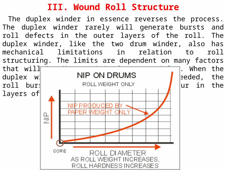
III. Wound Roll StructureThe duplex winder in essence reverses the process. The duplex winder rarely
will generate bursts and roll defects in the outer layers of the roll. The duplex winder, like the two drum winder, also has mechanical limitations in relation to roll structuring. The limits are dependent on many factors that will be discussed in future articles. When the duplex winder mechanical limits are exceeded, the roll burst and defect problems will occur in the layers of paper near the core.

III. Wound Roll StructureWHAT'S IN A ROLL OF PAPER?
When a roll is wound in a winder there are many contributing factors that help or hinder the roll structure. No matter how well the roll is structured, regardless of the type of winder being used, there are varying pressures and tensions within the roll. If one very carefully observes the layers of paper in a wound roll, varying bands of tension may be observed. The best way to observe this is to view what is called a "starred" roll. J. David Pfeiffer, in his studies of the internal pressures in a wound roll used the starred roll to illustrate non-uniformity of layers of paper in a wound roll. He noted the layers in positive tension on the outer inches of the roll appear significantly different then the buckled layers farther down in the roll that are in negative tension. The positive tension band on the outside of the roll is caused by a "hoop stress"-the outer layers exerting pressure towards the center of the roll to hold the roll together. It is interesting to understand that as paper is wound off the roll, the positive tension band or hoop remains although of a lesser dimension as the roll is unwound.

III. Wound Roll Structure

III. Wound Roll StructureWhen the roll is wound on the winder, tension is applied to the sheet
by the unwind stand. This tension is referred as the wound-in tension. Even though the backstand tension remains at a constant level, the wound in tension increases as the roll diameter increase. This particular roll was wound on a two drum surface winder. The increase in wound-in tension is attributed to the nip pressure between the paper and the winding drums. If this roll had been wound on a centerwind winder without nip at the same level of backstand tension, the roll would be so soft it would not support it's own weight. Tension levels two to two and half times would be required on the centerwind to reach a comparable hardness. The same is generally true of non-surface winding such as a duplex winder or duplex with centerwind.

III. Wound Roll Structure
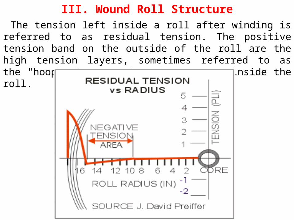
III. Wound Roll StructureThe tension left inside a roll after winding is referred to as residual
tension. The positive tension band on the outside of the roll are the high tension layers, sometimes referred to as the "hoop" that contains the pressure inside the roll.

III. Wound Roll StructureExamining the pressure inside the roll, the compressive pressure to
approximates the wound in tension profile.
III. Wound Roll StructureSHIPPING ROLL QUALITY
Probably the next, and most obvious question at this point is what does the preferred roll structure look like? To be able to answer that, an awareness of industry problems is required. The subject of shipping roll quality is a very involved topic requiring technical knowledge, know how, luck and perhaps a share of witchcraft. In recent years it involves a greater share of technical knowledge and know how. It is far to broad a subject to treat with any depth in a limited discussion. Good roll quality can be viewed from several perspectives including the papermaker, the end user and the machinery builder. These perspectives do not necessarily agree at all times.

III. Wound Roll StructureBREAKS/100 ROLLS
One of the important criteria for good running shipping rolls by the printer is the number of breaks at the printing press in the shipping rolls received from the papermaker. This is expressed in BREAKS/100 ROLLS. In some grades, quality has improved to the point that the term BREAKS/1,000 ROLLS is the criteria.
There are many reasons for breaks in a shipping roll, most considered to be roll structure defects. The main defect causing breaks in the printing press is an internal "burst" in the shipping roll or a "stressed" area that does not need much encouragement to burst during the converting process. These bursts are generally caused in areas of the shipping roll where the paper is wound to the point that the ultimate strength of the sheet is exceeded causing a break.

III. Wound Roll StructureCROSS MACHINE DIRECTION BURST
This burst is identified by a break in the sheet across the roll face. This burst is generally found in the outer few inches of the roll that is wound to tight (hard) on a two drum winder. The burst can be across the full face of the roll or a partial burst just enough to break down the web under stress.
MACHINE DIRECTION BURST
This burst is generally identified by a break in the shipping roll in the direction of unwinding. There are several reasons for a burst of this description. If there is a large variation in caliper of the sheet in the machine direction, the continual piling up of the thick caliper area will make a hard or soft "ring" in the roll referred to as a corrugation. The area adjacent to the hard ridge is smaller in diameter and can entrain air during winding. The air lubricated section of the roll has more layer to layer slippage (due to lower coefficient of friction) and will slip more than the high caliper area and cause a "shearing" in the machine direction. This type burst is most often found when their is a large variation in caliper over a short dimension across the roll face.
III. Wound Roll StructureIf the winder is operating on a sheet with a caliper of .003" and there is a
caliper variation of 5%, it hardly seems like much variation-.00015". When considering how many layers of paper are in a shipping roll, that small number becomes increasingly important. In a 40" diameter roll of newsprint, the 5% variation in caliper represents 3/8" on the radius of the roll. If there is an area 5" wide with that tolerance and each layer of paper winds the extra thickness, the 5" wide portion of the roll becomes 3/4" larger in diameter than the rest of the roll.
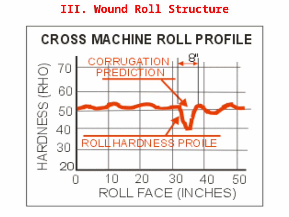
Another machine direction burst can be caused by entrained air in wide rolls-rolls that may have a reasonably uniform caliper. As the roll is wound, the roll entrains air which bleeds out the ends of the roll being wound. The wider the roll, the farther the air must travel to evacuate and the less air is removed from the roll. Depending on sheet characteristics, the layers at the center of the roll may be air lubricated and the layers at the edges of the roll have intimate contact. Again, unequal layer to layer slippage can cause a "shear" in the machine direction of the web. This defect is referred to as an air shear burst and is normally located 8 to 10 inches from either edge of the roll.
III. Wound Roll Structure

III. Wound Roll StructureStill another burst is called a "core burst" due to its proximity to the
core. This type burst is associated with duplex winding and is caused by over stressing the paper wound near the core. The over stressing can be caused by "internal gearing" of the core area in relation to the outer section of the roll, or just very heavy nip in the area immediately over the chuck that supports the roll during winding and unwinding. This burst or wrinkle is normally located very close to the core but has been identified as far as 10" from the core in some cases. This defect is normally within a couple inches of the roll edge and can exhibit a diagonal pattern as opposed to a straight across or in line burst. This burst may be accompanied by an accordion wrinkle (called a crepe wrinkle) adjacent to the rupture. The heavy weight of the roll in the projected area of the core chuck of the printing press will promote this type burst during unwinding at the printer although in many cases the burst is in the roll when it leaves the mill.

III. Wound Roll StructureNON STRUCTURE BURSTS
There are many reasons for breaks in the pressroom, too many to cover here. Some are non-winder related that can be caused by poor splicing techniques, calendar cuts, glue on the roll or shipping damage to name a few. A break in the printing press means a lot of lost production to the printer while the press is being cleaned up and rethreaded or a new roll loaded in the press unwind. Mills work extremely hard in sheet formation, winding and handling to keep breaks/100 rolls to a minimum.
PAPER DEFECTS
A paper defect involves any characteristic of the sheet that inhibits good runnability or quality at the winder or end users equipment.

III. Wound Roll StructureROLL STRUCTURE DEFECTS
These are defect that occur before the roll leaves the mill. Many end users have their own roll specifications that have to be met by papermakers. User specification can involve, tolerance on width and/or diameter, number of mill splices in a roll, straight sided (dish), or any number of conditions the shipping rolls must meet in addition to the detail specifications to meet an individual users needs.
There are a great number of identified known roll defects. Edge cracks, tension bursts, air shear bursts, bags, corrugations, crepe wrinkles, dishing, core bursts, offsets, turnovers, cuts,, interweaving, to name a few. Some categories have several sub-categories There are 9 different burst defects, 12 different wrinkle defects, 10 different crack and cut defects. It is reasonable to expect there are considerably more than a hundred known roll defects.
III. Wound Roll StructurePAPER VARIATIONS AND ROLL STRUCTURE
Poor roll structure can have many causes in a winding system. A major cause of structure problems is the paper itself. With today's paper making technology, the papermaker can produce a reasonably level sheet-but not perfect. Unfortunately, a winder is not always tolerant to cross machine variations in the sheet. It doesn't take much of a thickness variation to cause serious problems in the winding process.
Many mills producing coated grades, particularly wide LWC rolls, will routinely monitor rolls with a RHO Meter or other measuring instrument as a quality control check before the rolls leave the winder area. If a roll exhibits a poor hardness profile it will be routed to the reclaim winder for closer inspection. There is a possibility the reclaim winder can oscillate the unwind stand to spread a corrugation over a wider area than the shipping roll winder, expanding the area of the corrugation to a more acceptable width. If not, the roll may be cut down in width and salvaged in that manner.

IV. Wound Roll TestingThere are several reasons why a ROLL PRODUCER may want to test the roll
structure of shipping rolls (or jumbo reels): To determine the cause of specific roll defects such as crepe wrinkles or corrugations. As an aid to establishing the winding criteria of a newly installed winder or major rebuild of a winder or reel. As a quality control tool to check rolls before they are shipped to an end user.
A CONVERTER may want to check shipping rolls received from a roll producer: To determine how specific roll irregularities effect the efficiency of their machine. To supply creditable data to enable the roll producer to understand and resolve his concerns.
A major consideration of roll testing is the time and cost involved. Some testers are costly in themselves, some testers are automatic and can be used on the machine in real time such as a roll density analyzer. Others can be labor intensive and destructive such as the Cameron Strain Test or "J" Line testing. The more popular testers are the handhold units such as the Beloit Rho Meter, the Schmidt Hammer and Smith Needle.
Still another consideration, when choosing the type of tester to use is the ability of the tester to profile the roll diameter (MD) or across the winder face (CD). Testers like the Gap test, the J-line, the roll analyzer and the Smith needle are suited for testing profiles from the core to the OD but are not effective in cross winder direction. Conversely, The Beloit Rho Meter and the Schmidt Hammer are effective in the cross winder direction but not suitable for diameter profiling.

IV. Wound Roll TestingRegardless of the type of tester used, sampling size will have a great impact
on the results of testing (and cost). Sound testing results rely on the statistical data and the data interpretation. The results of this testing will not only effect the winding process but can be useful in making changes in the paper machine process to eliminate root causes of some of the defects generated during the winding, shipping and converting processes.
There are many causes of poor shipping roll quality including the many properties of paper. Some of those paper properties have a great impact on the roll structure. Unfortunately, many of the paper properties can not be changed due to economic or equipment considerations. This paper limits the discussion to tools used to test roll structure-the roll hardness and roll profile of the shipping roll.
As background to this discussion, for those not experienced in wound roll structure, it may be useful to review Wound Roll Structure and TNT The Tools of the Winding Trade, two papers previously posted in this series.

IV. Wound Roll TestingTHE BACKTENDER'S HELPER
The most basic tool used for roll testing is "the backtenders helper," a simple short length of stick used to manually strike the roll surface to judge the hardness and profile by the sound and "feel" of the stick impacting the roll surface. This is not a safe practice while machines are running and the absence of a means to quantify the test limits the value of the backtenders stick to a subjective determination of roll structure.
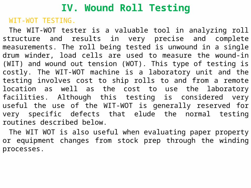
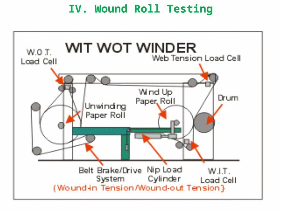
IV. Wound Roll TestingWIT-WOT TESTING.
The WIT-WOT tester is a valuable tool in analyzing roll structure and results in very precise and complete measurements. The roll being tested is unwound in a single drum winder, load cells are used to measure the wound-in (WIT) and wound out tension (WOT). This type of testing is costly. The WIT-WOT machine is a laboratory unit and the testing involves cost to ship rolls to and from a remote location as well as the cost to use the laboratory facilities. Although this testing is considered very useful the use of the WIT-WOT is generally reserved for very specific defects that elude the normal testing routines described below.
The WIT WOT is also useful when evaluating paper property or equipment changes from stock prep through the winding processes.
IV. Wound Roll Testing

IV. Wound Roll TestingDENSITY ANALYZER
The density analyzer uses encoders to measure web footage and roll revolutions. The diameter of the winding roll is measured using the ratio of the pulses of the encoders. The pulses from the encoders are counted over a time interval and sent to the computer for calculation. The density analyzer is an automated system for measuring roll structure, used in both portable and online winder applications. This system is the basis for many winder TNT control systems.
Many winder builders offer a service to temporarily fit up a portable density analyzer to monitor a winder over a period of time. A continuing printout will permit evaluation of the roll structure off the winder. This service is also useful when studying reel or supercalender wind-up conditions. It should be remembered that a roll analyzer can only measure roll structure by diameter and not across the winder face (CD). Regardless of this limitation, the density analyzer is a very valuable tool for monitoring wound roll structure.

IV. Wound Roll Testing
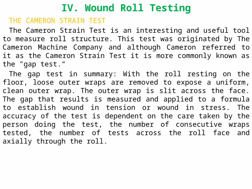
IV. Wound Roll TestingTHE CAMERON STRAIN TEST
The Cameron Strain Test is an interesting and useful tool to measure roll structure. This test was originated by The Cameron Machine Company and although Cameron referred to it as the Cameron Strain Test it is more commonly known as the "gap test.“
The gap test in summary: With the roll resting on the floor, loose outer wraps are removed to expose a uniform, clean outer wrap. The outer wrap is slit across the face. The gap that results is measured and applied to a formula to establish wound in tension or wound in stress. The accuracy of the test is dependent on the care taken by the person doing the test, the number of consecutive wraps tested, the number of tests across the roll face and axially through the roll.

IV. Wound Roll TestingCameron described the test procedure in the early 60s as follows:
First, measure the circumference of the roll.
Next, with the roll resting on the floor, slit the outer ply with a sharp knife or razor blade, using care to slit only through a single layer of paper.
With the palm of the hands, draw the severed sheet together as close as possible without introducing additional tension, and carefully measure the gap.
Then apply the formula A to determine residual stain or formula B to calculate wound-in tension in PLI.
(A) Residual strain = (Gap/(PI*diam))*100
(B) PLI = (Gap/(PI*diam)) * Caliper * Modulus of elasticity
The procedure hasn't changed since the above description appeared in TAPPI Standards. Experience indicates that using multiple layer testing and increased number of incidences of gap measuring across the face of the roll as roll width increases, result in improved statistical results.
Many labs and paper mills use the gap test frequently for roll structure analysis. The only tools needed are a tape measure, a magnifying glass with graduations to .0005", a calculator and marker pen.
For a more detail discussion, review The Cameron Gap Test and The Cameron Gap Test Gap 2, two papers previously published in this series.

IV. Wound Roll Testing

IV. Wound Roll TestingTORQUE WRENCH
A simple but effective tool for measuring the tightness of a roll at the core is a common torque wrench. By fitting up the torque wrench to a core adapter, the amount of torque required to slip the core can be measured. An example of it's use is checking rolls that have a tendency to telescope during the unwind process. After testing and statistical analysis determines the torque level considered acceptable, shipping rolls can be checked before shipment to the converter.

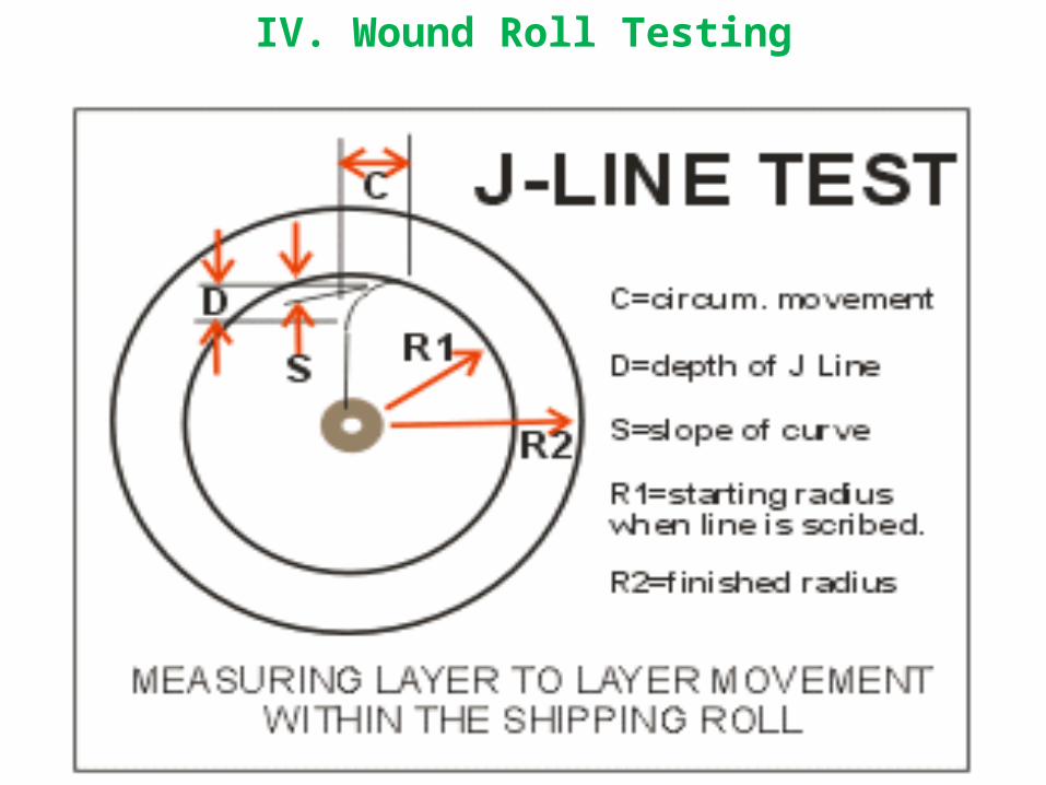
IV. Wound Roll TestingJ-LINE TESTING
J-line testing is a means to check the internal slipping inside a roll during winding (or unwinding). The test is simple and low cost and will indicate the magnitude of layer to layer slippage in the roll. The procedure: The winder is stopped, a straight is line is scribed from core to OD. The winder is restarted and again stopped after a time interval. The magnitude of J-line deformation indicates the amount of layer to layer slippage in the roll. This test is useful for determining the tendency for a sheet to crepe wrinkle. If conditions are right, generally speaking, the greater the magnitude of layer to layer slippage the greater the tendency to crepe. When the J-line is scribed on an unwinding roll, the amount of J line deformation is an indication of the internal gearing in the unwinding roll.
The greater the deformation the more likelihood that defects can occur during the unwinding process-particularly close to the core. The J-line tests outlined, can be repeated after making process changes to reduce slipping/and or gearing to determine if the changes were effective in reducing layer to layer slippage.
IV. Wound Roll Testing
IV. Wound Roll TestingBELOIT RHO METER
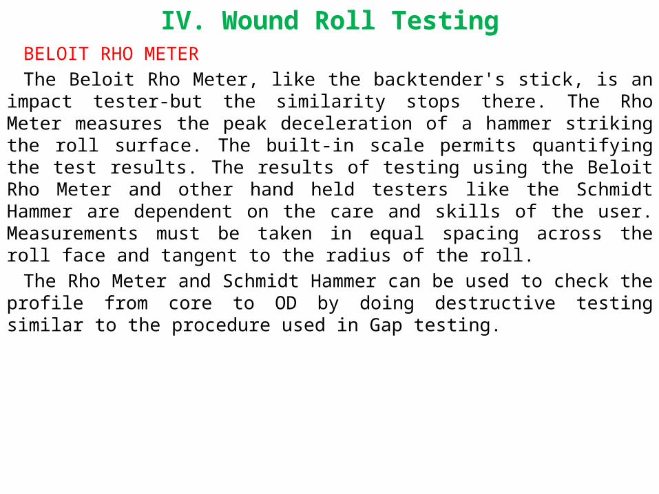
The Beloit Rho Meter, like the backtender's stick, is an impact tester-but the similarity stops there. The Rho Meter measures the peak deceleration of a hammer striking the roll surface. The built-in scale permits quantifying the test results. The results of testing using the Beloit Rho Meter and other hand held testers like the Schmidt Hammer are dependent on the care and skills of the user. Measurements must be taken in equal spacing across the roll face and tangent to the radius of the roll.
The Rho Meter and Schmidt Hammer can be used to check the profile from core to OD by doing destructive testing similar to the procedure used in Gap testing.

IV. Wound Roll Testing
IV. Wound Roll TestingSCHMIDT HAMMER
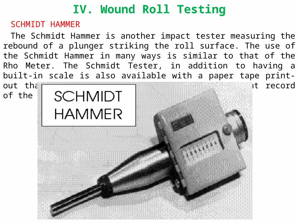
The Schmidt Hammer is another impact tester measuring the rebound of a plunger striking the roll surface. The use of the Schmidt Hammer in many ways is similar to that of the Rho Meter. The Schmidt Tester, in addition to having a built-in scale is also available with a paper tape print-out that gives an instant picture and a permanent record of the cross roll hardness profile.

IV. Wound Roll TestingSMITH NEEDLE
The Smith Needle tester is another hand held tester uniquely different from the previous testers described. The Smith tester measures the amount of force necessary to penetrate a needle between the wraps of a wound roll. Like the previous 3 testers, the Smith needle has a built in scale to quantify the results. In some cases, the Smith needle can be considered a destructive test. Unusual care should be used to minimize edge damage of the rolls being tested.

IV. Wound Roll TestingPAROTEST
PAROtest: Measuring Principle: The test is initiated by launching a spring loaded body against the test surface. The impact and rebound velocities are compared resulting in a instantaneous numerical hardness value. The tester is portable, easy to implement and extremely accurate. Digital Display and inherent data memory help make the PAROtester as easy to interpret as it is to operate. Accuracy to .5% - non contact measurement results in very little wear or maintenance. The information gathered by the instrument is down-loadable to a PC via an RS-232 output. A portable printer is available for immediate documentation of test results.

IV. Wound Roll TestingREFERENCE PAPER RECOMMENDATION
In the need for brevity, this paper is limited in the amount of detail regarding the use of testers and the requirement for sound use and statistical sampling. For those interested in detailed information on roll testing, a paper by David R. Roisum, titled "ROLL QUALITY MEASUREMENT" is highly recommended. A reprint is available in the TAPPI PROCEEDINGS, 1988 Finishing & Converting Conference. A copy can probably be obtained by contacting TAPPI Press.

IV. Wound Roll TestingReferences:
G. Erikson, C. Lydig, P. Komulainen, J. Viglund, - Measurement of Paper Roll Density During Winding J. David Pfeiffer, - Internal Pressures in a Wound Roll of Paper, J. David Pfeiffer, - Wound-off Tension Measurement in Paper Rolls Kenneth G. Frye, - Winding Variables and Their Effect on Roll Hardness and Roll Quality Al Hadlock, - The Principles of Winding David Roisum , - Roll Quality Measurements

V. TNT-Tools of WindingWHATEVER A WINDER MUST DO, it must have the ability to
produce good salable shipping rolls. All else is secondary. If the winder in question cannot provide good quality shipping rolls to the customer-the customer will very quickly find another source.
The basic tools that are available to the operator to structure shipping rolls are TNT, an acronym for Tension-Nip and Torque. There are winders in present use that only have the tools of TENSION and NIP available by design intention or just the age of the equipment. There are additional tools available such as larger diameter winder drums, tractionizing of the winder drum surface, articulating rider rolls, the quality of the sheet and sheet properties, etc. but they are not available to the operator.

V. TNT-Tools of Winding
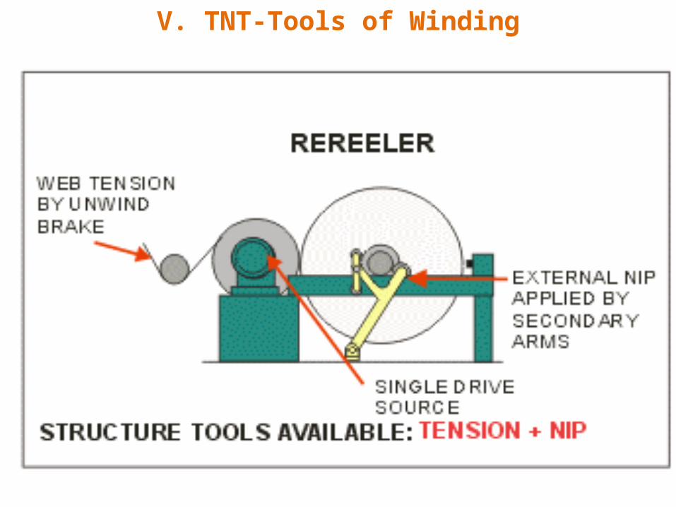
V. TNT-Tools of WindingTENSION comes from the "holding back" of the sheet from the unwind
brake. NIP is the sum of the external loads applied such station loads and rider rolls and in some designs the weight of the winding roll of paper on the winder drum(s). TORQUE is the rotational drive power applied at the winder drum (s).
In Part 2 in this series, Wound Roll Structure the basic shipping roll qualities were discussed as well as what happens inside a roll of paper when it is wound. To review, at the risk of being repetitive, just one more time to keep it fresh in our mind, "In the most basic definition an acceptable shipping roll must be hard enough at the core to support itself during unwinding, just hard enough at the OD to be handled and shipped without damage and a smooth transition in wound in tension (or hardness) from the core to the OD." Of course, the reality in the real world we live and work, the definition of a high quality shipping roll goes much farther than that. The axiom of roll quality is the same as that for any business: Build a better mouse trap and the world will beat a path to your door! The paper mill that can produce the best quality shipping roll to suit the end users' needs will get the bulk of and the most profitable business. To do this a winder must have all the tools available within the economics of the specific operations and just as importantly-know how to use them to advantage.

V. TNT-Tools of WindingPAPER MACHINE REELS & REREELERS
Winding operations such as paper machine reels do not usually have the basic tools necessary for structuring high quality jumbo rolls either by design or age of equipment. Reels can be modified to include a tension sensing roll for full tension control and centerdrives for torque control to include such tools to improve their roll structuring capability.
Rereelers fall into the same category as reels. Basic rereelers do not usually have the basic tools necessary for structuring high quality jumbo rolls but can modified to include such tools centerdrive for torque control to improve their roll structuring capability.

V. TNT-Tools of Winding
V. TNT-Tools of Winding

V. TNT-Tools of WindingTWO DRUM DUPLEX AND STANDARD TWO DRUM WINDERS
The two drum winders duplex or std have torque capability. All the core support two drum duplex winders were manufactured using a single drive motor and a harmonic drive tying the two drums together. This arrangement provided torque differential between the top and bottom winder drum.
The two major types of duplex winders are a mixed bag. When the core support duplex winder was first introduced in the 1960s to about the mid-1980s they were not equipped with a centerwind drive and therefor did not have TORQUE capability. Newer versions recently manufactured are equipped with centerwind drives and thus have the full TNT capability.

V. TNT-Tools of Winding

V. TNT-Tools of WindingSINGLE DRUM DUPLEX WINDERS
The core support duplex winder is manufactured with or without centerwind drives on the individual windup stations. Those without centerwind drives have TENSION/NIP capabilities while those equipped with centerwind drives have the full TNT capability.
The debate still is going on concerning the value of centerwind drives on the core-support duplex winder. Only the quality of the shipping rolls and the breaks/100 rolls feedback from the pressrooms will finally determine if the extra complexity and additional maintenance of the centerwind drives will quantify the ROI for such equipment.
All standard two drum winders are capable of differential torque between the winder drums with the proper equipment. Early 2 drum winders used a single motor drive and a Vari-pitch sheave arrangement tying the two drums together to provide torque differential. Some of the early winders using two drum drives used field weakening to provide a small torque differential or in some cases a booster was added to the outside drum to give more positive torque differential control. Modern two drum winders use a two motor drive with torque capability designed into the electric drive.

V. TNT-Tools of Winding

V. TNT-Tools of WindingIn the world of paper machine reels, rereeler and supercalendar windups there
appears to be acceptance of centerwind drives. There is a very high level of activity to retrofit centerwind drives on paper machine reels in both the primary and secondary winding position as well as an acceptance of new paper machine reel designs that inherently provide TNT in their design. In the case of rereelers, most new equipment includes centerwind drives and the retrofit activity in this area is high. In the case of supercalendar windups, the acceptance of centerwind drives appears to be universal. In stating this, one must recognize the complexity of a centerwind drive system for a multiple station duplex winder.
In a narrow context it is not fair to state that the only tools to structure a winding roll are TNT. TNT are the only tools available to the operator. The chart at left lists variables and machine elements that effect how a winder structures a shipping roll. Many of the variables listed are built into the machine by the machine supplier, as an example, the diameter of the winder drum and placement of spreaders. In some cases, modifying the variables after installation can improve winding. Some of the variables are within the control of the user (but not the winder operators) such as vibration, paper profile, etc. However, if the operators report these type conditions to superiors, they will more than likely be readily corrected.

V. TNT-Tools of Winding

V. TNT-Tools of WindingTENSION
Back tension is a contributing factor in the wound in tension in a shipping roll. Because the tension in the winder must be held reasonably constant during winding, it is not considered a variable tool in controlling roll quality. An additional factor to consider is the reduction in the backstand tension level by the time the sheet gets to the back winder drum nip.
The amount of capstan wrap has an effect in isolating the tension. Venta-grooving a winder drum to eliminate entrained air tends to maintain more intimate contact between the sheet, increasing the the grip of the sheet on the drum further isolating the back tension seen at the drum nip. When conditions are appropriate, tapering tension as the wound roll diameter increases may be beneficial to roll structure but not significant.

V. TNT-Tools of Winding
V. TNT-Tools of WindingNIP
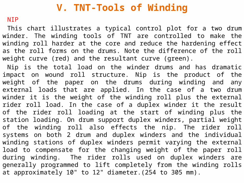
This chart illustrates a typical control plot for a two drum winder. The winding tools of TNT are controlled to make the winding roll harder at the core and reduce the hardening effect as the roll forms on the drums. Note the difference of the roll weight curve (red) and the resultant curve (green).
Nip is the total load on the winder drums and has dramatic impact on wound roll structure. Nip is the product of the weight of the paper on the drums during winding and any external loads that are applied. In the case of a two drum winder it is the weight of the winding roll plus the external rider roll load. In the case of a duplex winder it the result of the rider roll loading at the start of winding plus the station loading. On drum support duplex winders, partial weight of the winding roll also effects the nip. The rider roll systems on both 2 drum and duplex winders and the individual winding stations of duplex winders permit varying the external load to compensate for the changing weight of the paper roll during winding. The rider rolls used on duplex winders are generally programmed to lift completely from the winding rolls at approximately 10" to 12" diameter.(254 to 305 mm).

V. TNT-Tools of Winding
V. TNT-Tools of WindingTORQUE
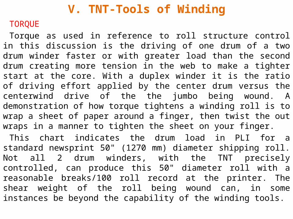
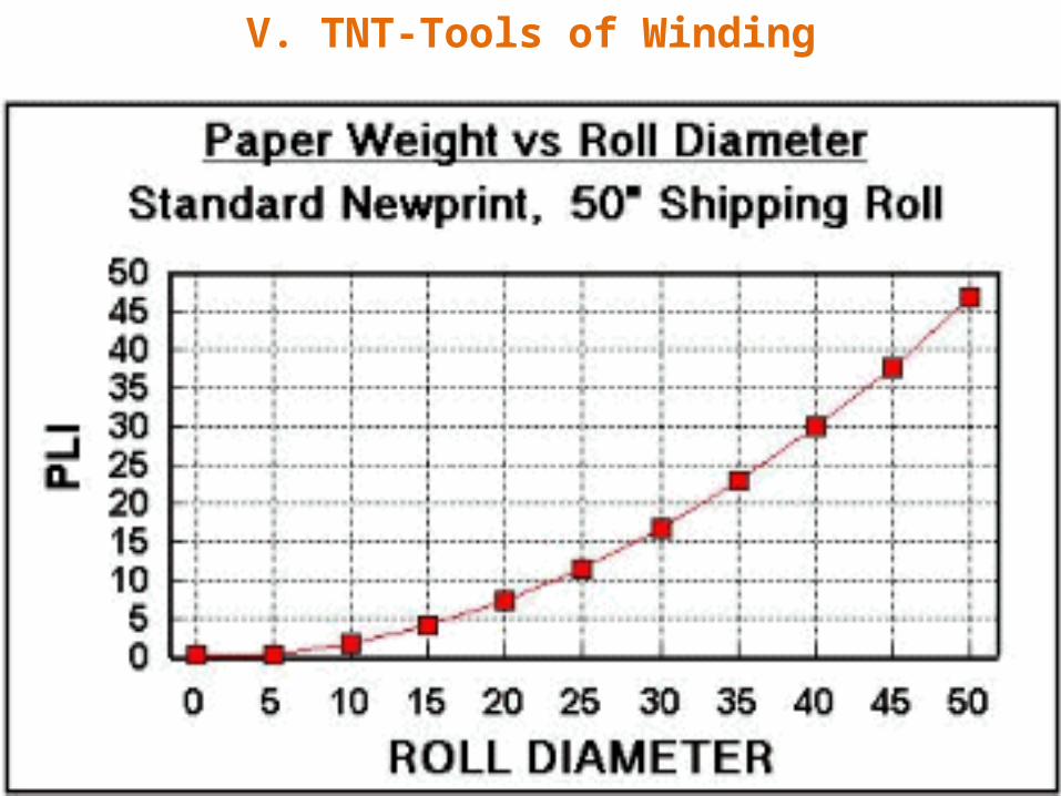
Torque as used in reference to roll structure control in this discussion is the driving of one drum of a two drum winder faster or with greater load than the second drum creating more tension in the web to make a tighter start at the core. With a duplex winder it is the ratio of driving effort applied by the center drum versus the centerwind drive of the the jumbo being wound. A demonstration of how torque tightens a winding roll is to wrap a sheet of paper around a finger, then twist the out wraps in a manner to tighten the sheet on your finger.
This chart indicates the drum load in PLI for a standard newsprint 50" (1270 mm) diameter shipping roll. Not all 2 drum winders, with the TNT precisely controlled, can produce this 50" diameter roll with a reasonable breaks/100 roll record at the printer. The shear weight of the roll being wound can, in some instances be beyond the capability of the winding tools.
V. TNT-Tools of Winding

V. TNT-Tools of WindingTUNING THE TNT
There are no hard and fast rules or programs that will guarantee success winding various grades of paper and roll sizes. Assuming the winder is set up and tuned to produce reasonably good shipping rolls, adjustments beyond that point must be based on reject reports within the mill and documentation from the end user of the rolls in question. What problems are being encountered? The defect and complaint list is lengthy and there are many variations of each of the defects. "The customer is always right" couldn't be more true when it comes to winding and shipping roll quality. In today's competitive environment user complaints cannot be ignored.
Tuning the winder comes down to specific complaints: Bursts on the OD, core bursts, crepe wrinkles on newsprint? The problem has to be approached much like a detective at a crime scene. Hunt for clues, understand the clue and then solve the case. When adjusting the winder, understand the specific complaint. Get a sample of the defect. Where in the roll does the defect happen? At the OD, near the core, in machine direction, cross machine direction, at the roll edges or center? When you can answer these questions you are ready to start looking at the roll structure off the winder.

V. TNT-Tools of WindingThe roll must be examined both in the cross machine direction as well as from the
core to the OD. The complaint you are chasing is your clue as to where to start in the roll.. Try to determine where in the cross machine and radial position the defect is occurring. If it can be isolated, say at the quarter point of the machine, or 6" (152 mm) from the core or 2" (51 mm) from the OD, it narrows down the search area significantly. Suppose your customer is experiencing core bursts that are causing breaks in the printing press, you should establish the distance from the core the breaks or bursts are happening.
There are hardness testers available that will permit the user to construct a picture of what the roll profiles look like. Both the Schmidt hammer and the Beloit Rhometer are hand held tools that permit measuring relative hardness across the face or from the core to the OD. The Smith meter is a tester that measures the penetration of a small needle that is inserted in the wraps along the roll edges. Any tester should be used with good judgment. When measuring across the face-draw a straight line and layout the increments of width to check. Mark the face of the roll in equal increments to measure the radial component. Hold the test instrument at right angles to the surface and try to apply the same trigger or actuating pressure for each reading. Criteria such as this must be followed to get uniform and reliable profiles. The Schmidt hammer and Rhomeer can perform a non-destructive roll test by unwinding the roll while supported in an unwind stand.

V. TNT-Tools of WindingAnother valuable test is the "gap" test developed by Cameron Machine
Company. This test is a very reliable means to measure wound in tension from the core to the OD. It is not as popular as other test because it is a destructive test and time consuming. With this test, a roll is "cleaned up by removing all loose wraps. Then a single wrap is slit across the face until it "pops"., The wrap is allowed to relax and the gap is measured and recorded. This test is performed in equal increments down through the roll. An efficient way to perform this test is to load a program in a laptop computer using the formula for gap testing. Entering the gap data as the roll is tested will produce a nice picture of the wound-in-tension when the test is complete.
For more information on roll hardness testers click here.
There are shortcuts that can be used in this test to save work and time. Using the example of the core burst noted above. If it is established the core bursts are happening 10" (254 mm) from the core or less, slab the roll down being tested to about 15" (380 mm) and start the gap test at this point. Better yet, if the winder is a duplex winder, stop the winder at 15" (380 mm) diameter, remove the roll in question to test and the winder can be restarted. This saves the time, work and mess of slabbing the roll down to size before testing.
V. TNT-Tools of WindingAfter the profile or wound in tension testing is complete a review of
the data will determine which of the winding tools may need reprogramming. Make changes in small increments and try to run a few rolls with the converter or printer before making additional changes. If the problem is not a "crisis" it might be prudent to make the changes to the programs, run a few rolls, record the changes and return to the original winder settings until feedback is received from the converter. This will reduce the backlog of finished rolls that may not have good runnability if the changes made did not solve the defect.
There are a group of winder designs or modifications that are sometimes referred to as winder tools due to their impact on wound roll structure. These designs are usually provided on new modern winders and in most cases can be retrofit to existing winders.

V. TNT-Tools of WindingDRUM SURFACE TREATMENT
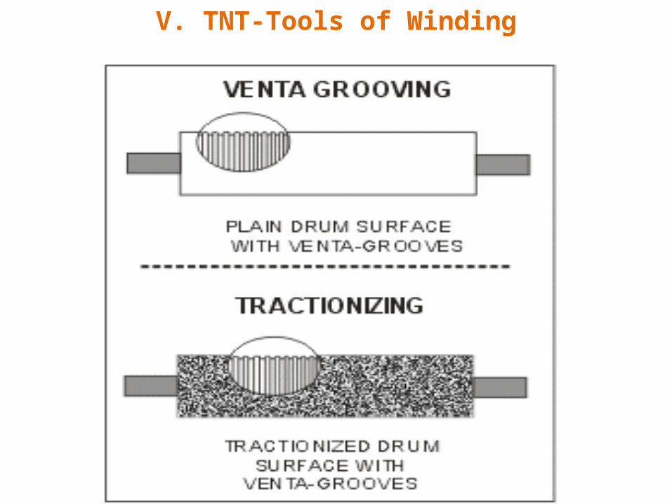
There are many types of drum surfaces used on winders. Two treatments that have impact on roll structure are tractionizing and Venta-grooving.
The purpose of tractionizing a winder drum is to increase the coefficient of friction to improve the differential torque transmission to the winding roll. When observing the amp meters of a winder, slippage can be noted by the amp reading variations. Tractionizing is a spray metal technique using tungsten carbide or molybdenum. In some instances, tractionizing winder drums will reduce vibration and bounce on grades with a rough surface. Tungsten Carbide is the most popular coating for tractionizing a winder drum and can be applied in the mill without dismantling the winder.
Venta-gooving is a very narrow groove pattern that aids in eliminating the surface air that travels with the web from becoming entrained in the winding roll of paper. Eliminating the entrained air stabilizes the layer to layer slippage within the roll during winding. Venta-grooving can be used in conjunction with other surfaces or grooving patterns.
V. TNT-Tools of Winding

V. TNT-Tools of WindingCORE CHUCK WEIGHT RELIEVING
Winders that do not have an efficient core chuck weight relieving system can cause "pinching" or loading of the A-Z rolls (front and back rolls of a set) causing defects in those rolls. Many early winders used hand wheel or chain and sprocket w/counterweight relief to unload the core chuck overhung loads, systems that are friction and maintenance intensive. The existing systems can be retrofitted with direct acting cylinder/programmed weight relief to improve the roll structure potential of the winder.

V. TNT-Tools of Winding

V. TNT-Tools of WindingReferences:
Kenneth G. Frye - Winding Technologies, Marti Karttunen and Hans Ehrnrooth - New single drum winding concept for lightweight printing papers. G. Forsberg - Modernization of Two Drum winders S.M. Hussain and W.R Farrell - Roll winding-causes, effects and cures of loose cores in newsprint rolls. Kenneth G. Frye - Winding Variables and Their Effect on Roll hardness and Roll quality

VI. Cameron Gap TestINTRODUCTION
When shipping roll structure quality becomes an issue, the internals of the shipping roll must be examined to understand what is happening in the winding process. There are many roll structure problems that are reasonably simple to diagnosis. Prior experience, basic knowledge and intuition may lead to an easy solution. There are other problems however that are not easily cured and must be investigated more thoroughly to understand the condition and apply a solution.
There are many tools available that can be used to measure roll condition and roll structure. They range from the simple to complex, their cost generally proportionate to the complexity. There are also destructive and non-destructive means to measure roll structure. The accuracy of testing is dependent on the tools to be used and the expertise and care used by the person performing the test.
To name the more common measuring devices, The WIT-WOT, Density Analyzer, Beloit Rhometer, Smith Needle, Schmidt Hammer, Core Torque Measuring, J-line, Gap and the Back Tender Stick. These all have their specific uses and when applied properly will give acceptable results. All but the Back Tender Stick are or can be configured to be quantitative tools.

VI. Cameron Gap TestTHE CAMERON STRAIN TEST
The Cameron Strain Test is an interesting and useful tool to measure roll structure. This test was originated by The Cameron Machine Company and although Cameron referred to it as the Cameron Strain Test it is more commonly known as the "gap test."
The gap test in summary: With the roll resting on the floor, loose outer wraps are removed to expose a uniform, clean outer wrap. The outer wrap is slit across the face. The gap that results is measured and applied to a formula to establish wound in tension or wound in stress. The accuracy of the test is dependent on the care taken by the person doing the test, the number of consecutive wraps tested, the number of tests across the roll face and axially through the roll.
Cameron described the test procedure in the early 60s as follows:
First, measure the circumference of the roll.
Next, with the roll resting on the floor, slit the outer ply with a sharp knife or razor blade, using care to slit only through a single layer of paper.
With the palm of the hands, draw the severed sheet together as close as possible without introducing additional tension, and carefully measure the gap.
Then apply the formula A to determine residual stain or formula B to calculate wound-in tension in PLI.
(A) Residual strain = (Gap/(PI*diam))*100
(B) PLI = (Gap/(PI*diam)) * Caliper * Modulus of elasticity

VI. Cameron Gap TestThe procedure hasn't changed since the above description appeared in
TAPPI Standards. Experience indicates that using multiple layer testing and increased number of incidences of gap measuring across the face of the roll as roll width increases, result in improved statistical results.
Many labs and paper mills use the gap test frequently for roll structure analysis. The only tools needed are a tape measure, a magnifying glass with graduations to .0005", a calculator and marker pen.
There are 3 steps to make a gap test
1. Clean up roll and mark increments for slabbing.
2. Make a clean slit across the roll face.
3. Measure gap.

VI. Cameron Gap Test
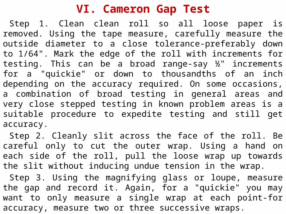
VI. Cameron Gap TestStep 1. Clean clean roll so all loose paper is removed. Using the tape
measure, carefully measure the outside diameter to a close tolerance-preferably down to 1/64". Mark the edge of the roll with increments for testing. This can be a broad range-say ½" increments for a "quickie" or down to thousandths of an inch depending on the accuracy required. On some occasions, a combination of broad testing in general areas and very close stepped testing in known problem areas is a suitable procedure to expedite testing and still get accuracy.
Step 2. Cleanly slit across the face of the roll. Be careful only to cut the outer wrap. Using a hand on each side of the roll, pull the loose wrap up towards the slit without inducing undue tension in the wrap.
Step 3. Using the magnifying glass or loupe, measure the gap and record it. Again, for a "quickie" you may want to only measure a single wrap at each point-for accuracy, measure two or three successive wraps.

VI. Cameron Gap TestThe results of the gap measurements should be graphed in a chart. A
handy way to do this is to use a laptop, put the formulas in your favorite spreadsheet, set up a template and enter data directly into the spreadsheet at the test station. The spreadsheet template can calculate and produce a chart similar to the one at left.
Assuming the chart above results from values taken at a single point at the center of the roll, the structure can be analyzed using the chart above. The gap test is more useful two or more three points across the face are used. Front, center and back is not uncommon on wider rolls, say over 40". The analysis then consider the cross roll profile as well as the radial profile giving a more definitive picture of the shipping roll structure. The number of points radically, across the face and number of subsequent wraps for each reading is a judgment based on the character and seriousness of the defect being studied.

VI. Cameron Gap Test

VI. Cameron Gap TestGAP TEST LIMITATIONS
Most people using the gap test on a regular basis recognize that gap test measurements may not be as reliable near the core as the outer wraps. This is principally due to the weight factor (or nip) at the floor line as the paper weight is removed during testing. Calculating the roll weight of a 40" diameter shipping roll vs. a 15" diameter shipping roll of almost any grade of paper will quickly make an awareness of the variability of roll weight and floor nip as the roll size is reduced. A couple of examples are listed in the table below.
40" diameter, 40" wide Shipping Roll
Grade 40" dia roll wgt 15" dia roll wgt 40" dia floor nip 15" dia floor nip
30# Newsprint 1200 # 160 # 40 PLI 4 PLI
30# Roto 2000 # 283 # 50 PLI 7 PLI

VI. Cameron Gap TestROLL NIP TO FLOOR
An additional factor that effects the accuracy of the gap test at smaller test roll diameters is introduced during the slabbing of paper from the roll for gap testing. As the paper is slit and falls away, the roll being tested rests on an increasingly higher pile of paper. If 12" of paper is slabbed off the radius, the roll being tested rests on a 12" cushion of paper. This cushion, lightly nipped, can cause instability and slipping during the gap test procedure, particularly if the paper has a low coefficient of friction.
It is recognized that these conditions corrupt the gap testing results at smaller test roll diameters. The practical question is, to what extent? Unfortunately there does not appear to be documentation that answers this important question.

VI. Cameron Gap Test

VI. Cameron Gap TestTo compensate for this change in roll weight and nip force at the floor
level of the test roll, it is recommended that a rod of substantial weight as possible be inserted in the core during testing to prevent layer to layer slippage during the last few inches of the roll.

VI. Cameron Gap TestWHAT'S IN THE FUTURE FOR GAP TESTING?
The limitation outlined above is a "red flag" in gap testing on grades that have a very low paper to paper coefficient of friction and roll structuring is a critical issue at the winder. A future paper will present Gap Test II that extends the practical use of the gap test.

VI. Cameron Gap TestINTRODUCTION
Winding Technologies, Part 5, titled "The Cameron Gap Test" describes the background and procedures of the gap test. To review that article click here. Gap II is a procedure developed in the field by Rudi Deeg, an engineer for Beloit Lenox. I had the good fortune to be at the mill during this period working on the same project as Rudi, participating as a consultant.. The Gap II story is my observations combined with valuable technical input from Rudi. Gap II is not a replacement for the Cameron Gap Test but an extension to enhance the test when superior roll structure control is required or unique conditions prevail.

VI. Cameron Gap TestTHE CAMERON STRAIN TEST
At the risk of being repetitive, the following summary is for those that may not have access to Part 5, "The Cameron Gap Test." If you have reviewed the information in Part 5 you can skip ahead to the Gap II section of this paper.
In summary: With the roll resting on the floor, loose outer wraps are removed to expose a uniform, clean outer wrap. The outer wrap is slit across the face. The gap that results is measured and applied to a formula to establish wound in tension or wound in stress. The accuracy of the test is dependent on the care taken by the person doing the test, the number of consecutive wraps tested, the number of tests across the roll face and axially through the roll.
The 3 basic steps to perform the gap test are:
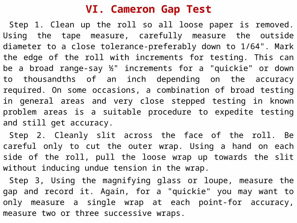
VI. Cameron Gap TestStep 1. Clean up the roll so all loose paper is removed. Using the tape
measure, carefully measure the outside diameter to a close tolerance-preferably down to 1/64". Mark the edge of the roll with increments for testing. This can be a broad range-say ½" increments for a "quickie" or down to thousandths of an inch depending on the accuracy required. On some occasions, a combination of broad testing in general areas and very close stepped testing in known problem areas is a suitable procedure to expedite testing and still get accuracy.
Step 2. Cleanly slit across the face of the roll. Be careful only to cut the outer wrap. Using a hand on each side of the roll, pull the loose wrap up towards the slit without inducing undue tension in the wrap.
Step 3, Using the magnifying glass or loupe, measure the gap and record it. Again, for a "quickie" you may want to only measure a single wrap at each point-for accuracy, measure two or three successive wraps.

VI. Cameron Gap TestGAP TEST LIMITATIONS
Most people using the gap test on a regular basis recognize that gap test measurements may not be as reliable near the core as the outer wraps. This is principally due to the weight factor (or nip) at the floor line as the paper weight is removed during testing. Calculating the roll weight of a 40" diameter shipping roll vs. a 15" diameter shipping roll of almost any grade of paper will quickly make an awareness of the variability of roll weight and floor nip as the roll size is reduced. A couple of examples are listed in the table below.
40" diameter, 40" wide Shipping Roll
Grade40" dia roll wgt
15" dia roll wgt
40" dia floor nip
15" dia floor nip
30# Newsprint
1200 # 160 # 40 PLI 4 PLI
30# Roto 2000 # 283 # 50 PLI 7 PLI
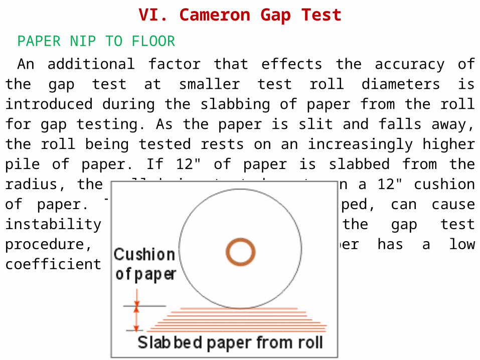
VI. Cameron Gap TestPAPER NIP TO FLOOR
An additional factor that effects the accuracy of the gap test at smaller test roll diameters is introduced during the slabbing of paper from the roll for gap testing. As the paper is slit and falls away, the roll being tested rests on an increasingly higher pile of paper. If 12" of paper is slabbed from the radius, the roll being tested rests on a 12" cushion of paper. This cushion, lightly nipped, can cause instability and slipping during the gap test procedure, particularly if the paper has a low coefficient of friction.

VI. Cameron Gap TestIt is recognized that the conditions outlined above corrupt the gap
testing results at smaller test roll diameters. The practical question is, at what point and to what extent? Unfortunately there does not appear to be documentation that answers this important question. It would appear that increased floor nip would reduce the tendency to corrupt to findings.
To compensate for this change in roll weight and nip force at the floor level, it is recommended that a rod of as substantial weight as possible be inserted in the core during testing to prevent layer to layer slippage during the last few inches of the roll.

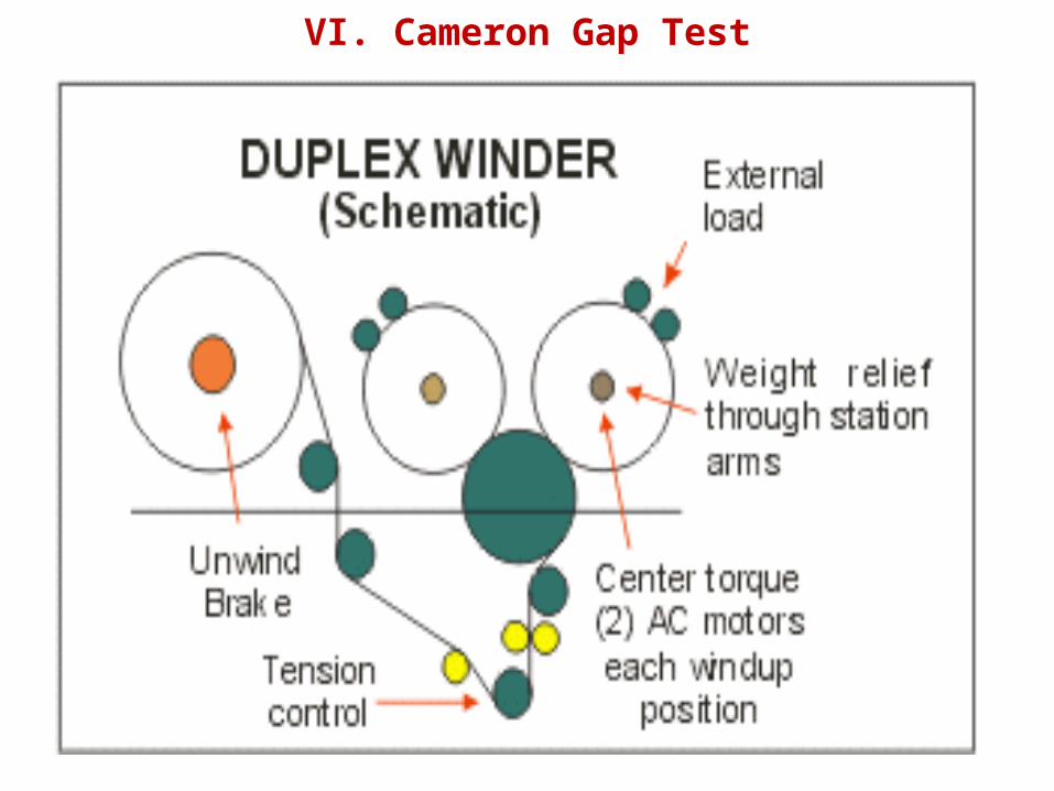
VI. Cameron Gap TestGAP II - A MODIFIED GAP TEST
In the course of my experience in finishing I was fortunate to be involved in a major duplex winder project and startup by Beloit. The purpose of this article is not to sell Beloit or their machinery but to relate the findings concerning the use of the Cameron Gap Test as it effected this startup. The experience just happened to occur on a Beloit machine.
During the start-up of the winder, the gap test was extensively used to tune the winder and eventually confirm anticipated and desired roll structures. The winder was a duplex winder using center torque at the core. The system, through which the center torque was applied had two integrated AC motors, one each end of each individual rewind station, driving via a right angle gear drive into the core with torque expanding chucks. Very direct, no losses. Whatever power was transmitted in the form of torque had to be in the roll unless there was slippage at the winder drum which did not occur.
VI. Cameron Gap Test

VI. Cameron Gap TestAfter the drive was tuned and electrically confirmed that the set points
followed, the roll structure should at least reflect those same trends. Instead the winder was getting regressive values instead of progressive values as it neared the core. The curve shown is typical.
A couple of things subtly happened. The paper being highly coated and supercalendered had a very low paper to paper coefficient of friction (slippage occurred earlier than anticipated from testing other grades), consequently slippage in the roll during the gap test occurred relatively early, sometimes as early as 22" to 24" diameter.
This was helped by a softer nip between the cut paper on the floor and the remaining roll as well as higher tensions run with this LWC compared with earlier tests with other grades. Another phenomena was that while cutting and handling the roll during testing, the roll moved minutely, i,e. rocking it back and forth. This gave the paper an opportunity to slip through the nip at floor level long before this would occur had everything remained static.

VI. Cameron Gap Test
VI. Cameron Gap TestOnce the inefficiencies of the measuring practice was recognized,
corrective measures were taken. to be sure any slippage in the nip was excluded due to instability of the nip.
For positive control of the roll during gap testing, a small "sawhorse" was made with a 5" angle bar on top (shown in black), The sawhorse was 60" in length to accommodate the widest roll to be tested. A pair of special removable C-clamps with V-blocks on the clamping plates were also made (shown in red). The clamps are fitted up on each end of the roll and the down force adjusted to the roll via a reasonably stiff aluminum tube through the core. The OD of the aluminum should be consistent with the ID of the core. All this equipment could be handled easily by one person. This arrangement insures that the roll being gap tested would be under a controlled nip with the sawhorse throughout the testing procedure. Each time paper is slabbed from the roll, the clamp is adjusted to stabilize the system.

VI. Cameron Gap Test
VI. Cameron Gap TestThe modified procedure was to gap the test roll in the usual manner on the floor down
to 30" diameter. At 30" diameter, the outer wraps of paper were fastened as securely and tight as possible. The 30" roll was lifted from the floor and it's "cushion" of paper and placed on the sawhorse. The clamps were fixed in place and adjusted and testing continued.
From the very first roll after continuing testing, the residual strain followed the tension curve of the winder to the "T". Because of the design of the winder, the direct center drive and 100% controllable nip which was constant in the 6 to 8 PLI area throughout the roll buildup, it could be reasonably assumed that the programmed operating parameters came to the roll 100% without any impairing geometry, similar to the two drum winder's increasing nip with the weight of the roll.
Once the merits of clamping the roll down were recognized, in retrospect, the entire roll could have been placed on such a stand with an adequately designed support as long as an available crane is in the area. This will assure the same stable conditions throughout the entire testing process.
There are a number of curves in the data base from this project, which, if looking at them in view of the above, might not reflect, so much the actual residual strain, as they show slippage during the gap test.
One never knows, but to make sure that this does not happen, the above procedure is mandatory.

VI. Cameron Gap Test

VI. Cameron Gap TestThe Gap II procedure as outlined above, in no way invalidates or
minimizes the importance and use of the Cameron Strain Test as originally developed by Cameron Machine Company. Gap II is an important contribution in extending the use of the gap test into the core area, which, in today's world of jumbo rolls, is of fundamental importance. Using the described procedure, Gap Test II provides a tool that can be used with a high level of confidence on those installations that have unique requirements, and particularly useful in setting up a new winder installation.
Note: Minor corrections (inconsequential typos) and feedback note added August 16, 1997.

VII.1 Winding Scrap Book – 2 Duplex WinderPrior to the 1960s the only winder available to paper mills were two drum
winders. Although the two drum winder served the industry well for the times, it had a serious limitation-it did not have the ability to wind very large rolls. Large jumbo reels were sent directly from the paper machine reel to the subsequent finishing operations such as the off-machine coater, supercalender or shipping roll winder. Because many of the reels could have paper machine breaks or poor paper, the subsequent finishing operations were inefficient due to stopping to cull out poor paper or splicing paper machine breaks in the reel.
Some mills attempted to use a 2 drum winder specially modified with core shaft holders that could accommodate reel spools. In this way they could rewind machine reels that had breaks or poor paper and send an improved though smaller jumbo to the subsequent in-house finishing operations. Editing the jumbo in this manner did improve the efficiency of the subsequent operations but limited the size of the jumbo going to the operations which had it's own negative impact on process productivity.

VII.1 Winding Scrap Book – 2 Duplex Winder

VII.1 Winding Scrap Book – 2 Duplex WinderIn the very late 50's and early 60's a "rereeler concept" developed. The
rereeler essentially was a paper machine reel without primary arms and trim slitters mounted ahead of the reel drum to trim the deckle edge of the jumbo. The rereeler was a batch operation making it possible to stop and splice paper machine breaks and remove off-quality paper. This resulted in a large jumbo reel (sometimes referred to as a "bull-eye" reel) with few imperfections going to the in-house finishing operation. The rereeler, winding on reel spools, had the ability to produce an "edited" jumbo as large as the paper machine reel of improved structure. . The rereeler greatly improved the finishing line efficiency and permitted larger and larger jumbos to be sent down the line. In a short time most coated paper mills used rereelers between the paper machine reel and off machine coater or super calenders to make large bulls-eye" reels for the in-house finishing operations.
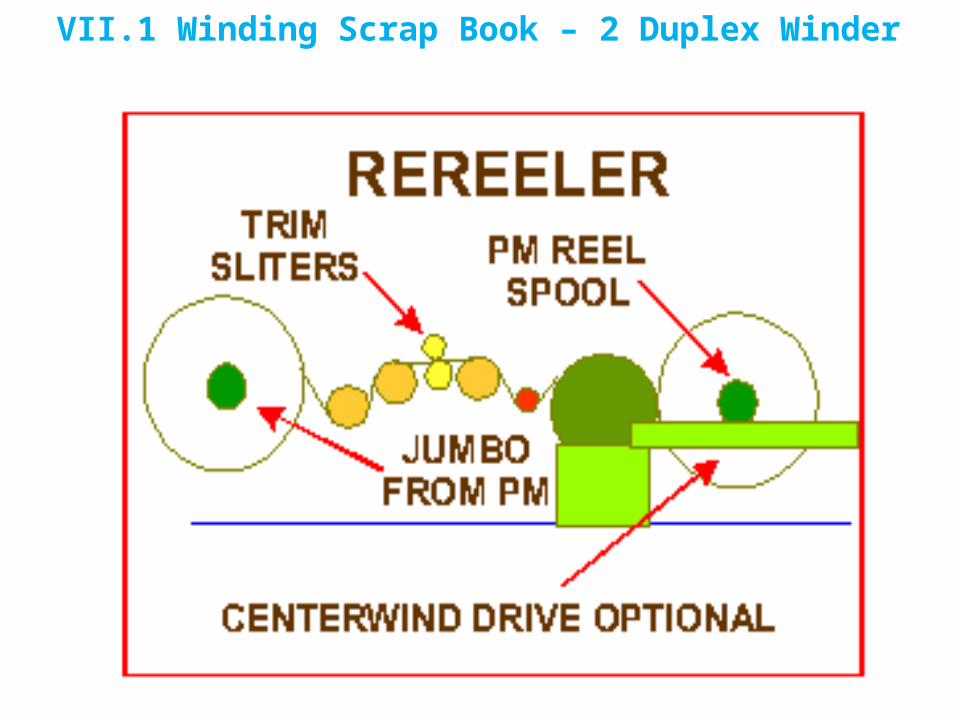
VII.1 Winding Scrap Book – 2 Duplex Winder

VII.1 Winding Scrap Book – 2 Duplex WinderWith the knowledge that centerwind drives greatly improve the winding
capability of the rereeler, it is not uncommon to see rereelers equipped with a centerwind drive which not only improves the jumbo structure but also reduces waste and permits winding larger jumbos. Although now taken for granted, the rereeler was a tremendously important development that had a significant impact on all in-house finishing operations, greatly improved the production capability of the shipping roll winder and indirectly effected the runnability and waste reduction of the end user of the paper.
Things started to happen rapidly in the early 60's in the winding area. The changes in paper properties had a great impact on the ability of two drum winders to produce well-structured shipping rolls in the widths and diameters that printers and converters were requesting. The lighter weight and denser sheets were adding to the winding problems. It was obvious that a new concept winder was required.

VII.1 Winding Scrap Book – 2 Duplex WinderThe ability of paper machine reels (and rereelers) to wind large full width
jumbos did not go unnoticed. In a short time the rush was on by winder builders to adopt the "paper machine reel" concept for shipping roll winding. The new concept winders were called "duplex" winders, the name referring to the fact the duplex winder wound shipping rolls on alternate sides of the winder drum(s).
The earlier duplex winder concept was called a "core support winder" because like it's mentor, the paper machine reel, it supported the full weight of the winding roll on a core shaft. Unlike the paper machine reel, the shipping roll winders used intermediate slitters and wound rolls alternately on opposite sides of the drum on shipping roll cores. Here again was a development that would have positive repercussions all through the printing papers segment of the paper industry.

VII.1 Winding Scrap Book – 2 Duplex WinderOne of the first duplex winders was a single drum version. This concept closely
emulated the paper machine reel in that it used a single drum for winding. The very first of this generation of winders was called the MIR which stood for Multiple Individual Rewinds. The single drum version was produced in several specific designs by several winder builders. The early versions of the single drum duplex winder using fixed stations to support the winding roll did not have centerwind drives but modern versions are now available with this feature.
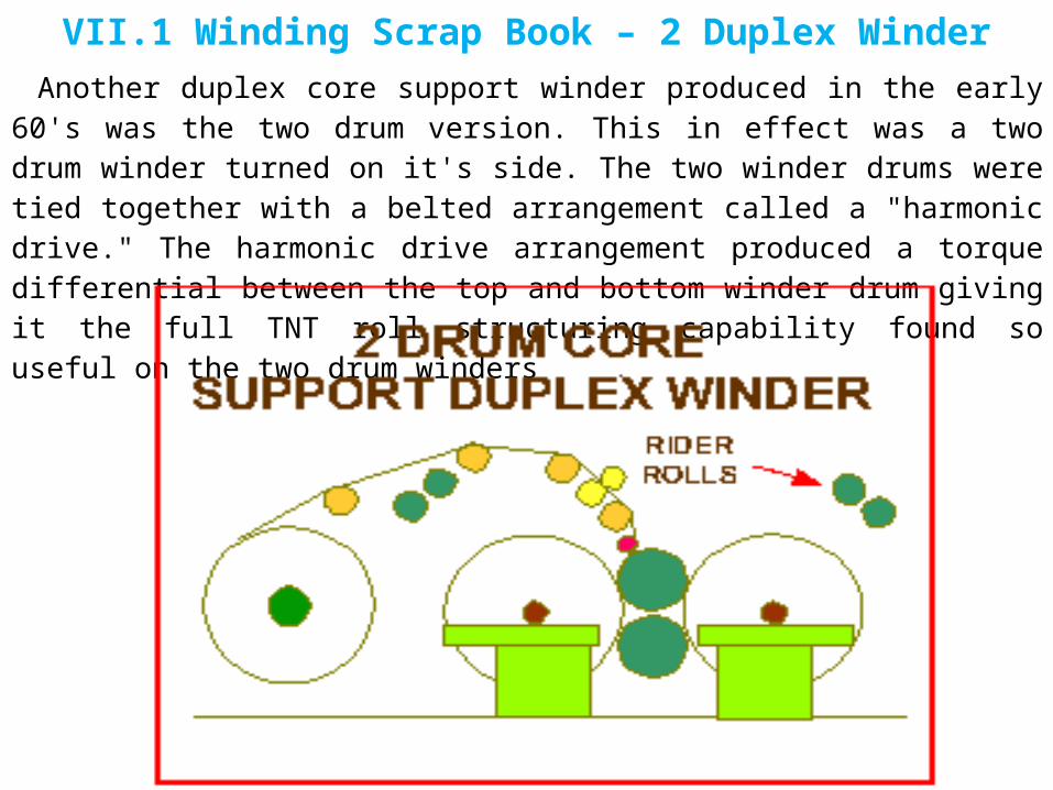
VII.1 Winding Scrap Book – 2 Duplex WinderAnother duplex core support winder produced in the early 60's was the two drum
version. This in effect was a two drum winder turned on it's side. The two winder drums were tied together with a belted arrangement called a "harmonic drive." The harmonic drive arrangement produced a torque differential between the top and bottom winder drum giving it the full TNT roll structuring capability found so useful on the two drum winders

VII.1 Winding Scrap Book – 2 Duplex WinderStill another version of the core support winder was produced that used pivoted arms
as opposed to stationary stands to support the winding rolls. This concept had full centerwind capability using hydraulic or electric motors, depending on the builder. The hydraulic version was the first duplex concept to have individual centerdrives on both ends of each individual roll of the set.

VII.1 Winding Scrap Book – 2 Duplex WinderAs paper properties continued to change and printers and converters
demanded wider and larger diameter rolls with better runnability in the pressrooms to improve their operating efficiency, core support winders started to fall on hard times on some applications. When winding wide, large diameter rolls of roto papers, the additional weight supported by the core shaft was resulting in wound roll defects near the core. A new generation of duplex winders called drum support duplex winders were developed. The core at start was held in place by the chucks and rider rolls and supported by the winder drum. As the roll builds during winding, the roll weight load is shared by the core chucks and winder drum. The rider rolls generally lift off the set at about 10 to 12"diameter. Roll structuring is programmed through rider roll load, core chuck relieving or load, tension control and centerwind torque if available

VII.1 Winding Scrap Book – 2 Duplex Winder

VII.1 Winding Scrap Book – 2 Duplex WinderThe first of this generation of duplex winders used a relatively large center drum and
overhead mounted rider rolls and core chuck holders. Roll structuring was accomplished by tension control and pneumatic control of rider roll load and core chuck load and relieving programs. The early versions of this concept did not have centerwind drives but the feature was available in later models. The core support winders rely heavily on computerized control of the winding variables.

VII.1 Winding Scrap Book – 2 Duplex WinderOne of the available core support duplex winders uses a large paper carrying roll
between a pair of horizontal winder drums. This particular winder was initially furnished with a single electric centerwind motor at each winding station to provide torque control during winding.

VII.1 Winding Scrap Book – 2 Duplex WinderThe final drum support winder to be reviewed uses a single winder drum. Each roll
of a set is supported by a pair of pivoting arms that contain integral electric motors within the arm framework. The integral motor in each arm results in a minimum electric drive size profile in the cross machine direction permitting narrow slits across the full width of the winder face. The builder suggests that the use of centerwind motors on each end of the winding roll results in symmetrical torsioning of the winding set with a maximum torque availability.

VII.1 Winding Scrap Book – 2 Duplex WinderIt is obvious that each of the winder applications shown in this scrapbook have their
own unique advantages and disadvantages. Application to a certain extent is generally grade specific. Important considerations are minimum slit width and productivity potential. It is universally recognized that the productivity of a duplex winder does not compare favorably with that of the two drum winder. Recent innovations in duplex winder designs have made great improvements in the production capability of all duplex winder concepts, The winders illustrated have demonstrated their success in winding high quality shipping rolls for the grades they are designed to handle. Most are available in manual or automated designs for flexibility to accommodate structure and production demands.
This type of winder appears to be in a steady stream of upgrading to wind heavier, high quality shipping rolls and increased productivity.
This scrapbook contains conceptual sketches of winder configurations in present use in the Pulp & Paper Industry. The sketches are not drawn to scale and use generic sheet runs and are not intended to represent equipment as designed and sold by winder manufacturers. For specific details, arrangements, specifications or other issues concerning the concepts illustrated, contact a manufacturer that produces such concepts

VII.2 Winding Scrap Book – Two Drum WinderPrior to the 1960s a paper mill did not have much choice in winder designs.
The two drum winder with equal size drums and a horizontal slitter section was the dominant, and in a practical sense, the only winder concept available. A couple innovative winders were produced but did not have wide acceptance which resulted in a very short life.
This vintage winder used cast iron frames and wound the rolls on a full width winder coreshaft on either iron pipe or paper cores. Maximum winder speed was determined by a rough formula of 2.5 times the maximum paper machine design speed. The winder operation was manual with a cycle time more than adequate for the times. Paper machines in this period were operating in the 2000 FPM maximum speed range. The winder drive used a single motor drive with a belt tie between the two winder drums. Tissue machines used a similar winder the notable exceptions being a surface driven unwind stand and a coreshaft weight relieving system to maintain bulk. A modern version of the horizontal sheet run two drum winder is still produced today in very limited numbers for special applications.

VII.2 Winding Scrap Book – Two Drum Winder

VII.2 Winding Scrap Book – Two Drum WinderThe vertical slitter section 2 drum winder appeared in the late 60's and was
popularized in the 70's. There was a lot happening in winding in the 60's. The early 60's saw the first two motor- torque differential drives, load cell tension systems, sectional paper carrying rolls, dual component spreader elements and other significant WINDER developments.. The first automatic slitter sections appeared in the late 60's. Shaftless winding, a unique and different concept was just coming to being. The change that had the greatest impact on winder designs was the advent of fabricated winder frames as opposed to cast iron. This permitted a flexibility in design not possible in the past.
To accommodate the changes in paper grades, basis weights, sheet densities and other paper properties, there was a great flurry of roll structure control systems and larger diameter winder drums to improve shipping roll quality to meet the demands of larger shipping roll sizes. As the two drum winder matured and was mechanically opimized to the fullest the "traditional" two drum winder was found lacking when winding large, heavy shipping rolls of dense grades of paper, particularly in the coated and super calendered papers.
The duplex winder concept emerged in the early 60's but due to it's poor productivity performance, winder builders continued to develop new two drum winder designs to wind heavier shipping rolls and maintain the productivity advantages of the two drum winder.

VII.2 Winding Scrap Book – Two Drum Winder

VII.2 Winding Scrap Book – Two Drum WinderWorking in concert with paper mills, winder builders designed new and
innovative concepts to extend the usefulness of the two drum winder . One of the earlier developments was the "unequal drum diameter" concept. When winding on the two drum winder with unequal drum sizes the major portion of the winding roll weight was transferred to the broader nip of the larger winder drum reducing the PSI load of the paper winding on the drums resulting in less "wound in tension" caused by drum nip load.

VII.2 Winding Scrap Book – Two Drum WinderAnother development was "soft nip winding". Again the goal was for a broader drum
nip to reduce the tension being wound into the roll. This winder concept uses a resilient material on one of the winder drums that can deform under load, producing a wider nip. In some installations, the "soft nip" concept is further enhanced by the application of a narrow based articulating rider roll that minimizes the effect of caliper variations in the web.
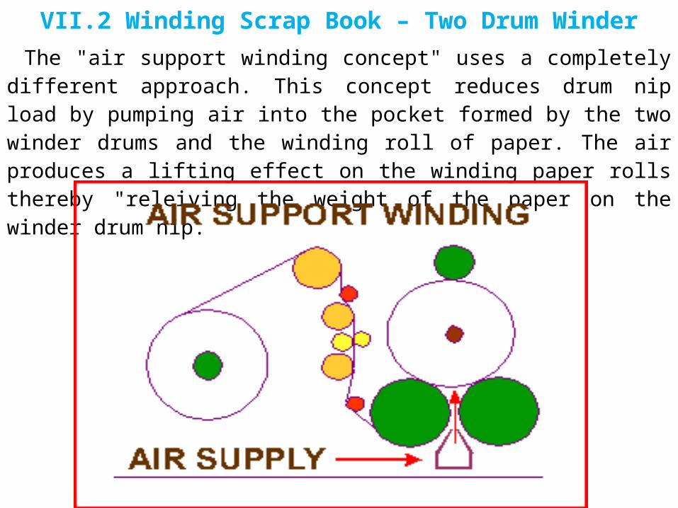
VII.2 Winding Scrap Book – Two Drum WinderThe "air support winding concept" uses a completely different approach. This
concept reduces drum nip load by pumping air into the pocket formed by the two winder drums and the winding roll of paper. The air produces a lifting effect on the winding paper rolls thereby "releiving the weight of the paper on the winder drum nip.

VII.2 Winding Scrap Book – Two Drum WinderAnother very unique approach is the "three drum winder" concept. This
concept embodies both the two drum and duplex approach. The concept in effect is a pair of two drum winders, the common center drum acting as the second drum on each of the two drum winders. The winding rolls in a set are wound on alternate pairs of drums. This concept has several advantages not the least of allowing individual rolls to be weight relieved.
VII.2 Winding Scrap Book – Two Drum WinderYet another unique configuration is the "belted winding" concept. The Belted
winder replaces one of the winder drums of the traditional two drum with a belt arrangement. It is only similar to other concepts in that the goal is to broaden the nip that supports the winding roll of paper. As the roll builds in size during the winding process, more of the wound roll surface bears on the belt arrangement-in essence widening the drum nip proportionate to wound roll diameter.
All the "enhanced" two drum winder concepts described are operating successfully today in the marketplace. For the most part these designs are grade specific and in many instances the concepts are adaptable to retrofit on existing traditional two drums.

VII.2 Winding Scrap Book – Two Drum Winder

VIII. Paper Machine Reel TechnologyTHE EFFECT OF MARKET CHANGES ON WINDING
In the recent past, market demands have encouraged papermakers to develop many new grades of paper with very specific characteristics to meet user requirements. Not only have papermakers developed new grades but are producing those grades at increasingly higher paper machine speeds. This coupled with the demand for larger, higher quality shipping rolls from the pressrooms present both winder builders and paper mill finishing operations with unique challenges. Paper mill finishing rooms and builders, working together have developed new winding systems to meet the demands. The reality is, that even with the great progress in winding, new challenges and obstacles keep occurring that require changes in operation that are outside the area of finishing room responsibility.
The need for higher winder productivity effects other elements of the paper machine. One element is the paper machine reel. To attain more productivity from operations that follow the paper machine such as off machine coaters, supercalenders and winders, mills process a greater number of sets from the jumbo. To do this, the jumbo has become increasingly larger. Jumbos to 90" (2286 mm) diameter processing coating grades and 120" (3048 mm) on other grades are common. This trend has occurred slowly over the years and only recently recognized as a problem.
Winder builders and winder operators were first to feel the effects of this trend by facing situations that challenged their technology and expertise. In an effort to understand their inability at times to produce shipping rolls with fewer defects, they looked to the end user for help. Investigations with end users of shipping rolls, in this case the pressroom, revealed that defects in shipping rolls originated in specific areas of the jumbo from the paper machine reel.

VIII. Paper Machine Reel TechnologyDEFECTS BY POSITION IN JUMBO
This chart displays the results of one such study. It is readily apparent that the defects in a jumbo are not uniformly distributed throughout the jumbo but disproportionately located in areas closer to the reel spool. This chart shows a roll tracking study of defects in the relative radial position as reported by a pressroom. In the way of explanation, if it is not obvious, the chart lists the defects in sets off the reel in order of unwinding the jumbo, first set being the outside set of a jumbo and the last set being the paper closest to the reel spool. Other studies on various grades of paper have produced similar results.
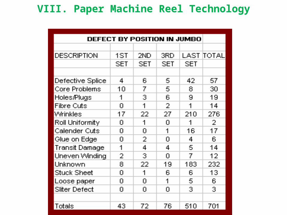
VIII. Paper Machine Reel Technology

VIII. Paper Machine Reel TechnologyThis chart dramatically illustrates the findings noted in the chart above. Fully 72% of
the defects in this study occurred in the last set of paper off the jumbo, the paper closest to the reel spool. What does not show in this chart but is recognized in the details of the study is that many of the defects occur in the A & Z rolls of the winder (front and back side rolls) caused by over stressing the paper at the ends of the reel during the reeling process.
Once this phenomena was recognized, questions came immediately to mind. What causes it? How wide spread is the problem? What can be done to relieve the situation? In looking at winder operations in general, it is not uncommon to see operators slowing down when winding the last set off the reel. It was also observed that many times the operator will leave as much as 2" to 3" of paper on the reel spool. Operators discovered by experience that the last set off the reel does not run as well in the winder as the other sets and many times a winder break will occur in the last couple of inches of paper near the reel spool. Both of these observations are clues to the seriousness of the problem.

VIII. Paper Machine Reel Technology

VIII. Paper Machine Reel TechnologyOperators discovering that leaving paper on the reel spool during the unwinding
process to avoid breaks lead to the acceptance of this practice to improve overall general operating efficiency. As the problem became more severe, the product waste became an issue of concern. Several studies have been performed in mills to discover the extent of paper losses due to roll defects near the reel spool. The following study is only one of many. This is a study of a single LWC paper machine over a one year period. The operators were leaving several inches of paper on the reel spool at the rereeler not only to reduce breaks at the rereeler but more importantly to reduce breaks at the OMC.
The losses shown in this study represented millions of dollars at current product prices at the time of the study. In addition to product losses there are other losses to consider. The breaks at the off machine coater attributed to over-stressed paper at the reel spool of the machine reel represent about 16 1/2 calendar days of lost coater use. Add to that the energy cost to re-pulp the 7000 tons of paper tossed into the broke pit and the extra work required by the operators to slab and clean up each reel spool the magnitude of the problem becomes apparent.

VIII. Paper Machine Reel Technology
VIII. Paper Machine Reel TechnologySimple cures were tried such as additives in the stock, making smaller jumbos or the
use of larger reel spools. All these type cures yielded some marginal return but the cure is not a simple one. The consensus seemed to be to look at the machine reel itself.
The winders that efficiently produce the large shipping rolls today are technologically advanced when compared to only a few years ago. To produce high quality shipping rolls with a minimum number of defects, it was discovered that success was not only using the tools of TNT (Tension-Nip-Torque) to the utmost precision during winding but an understanding of the laws of physics and how they effect weight distribution in the winder was needed to control the nip forces that were unmanageable in some winder configurations.
VIII. Paper Machine Reel TechnologyTHE PAPER MACHINE REEL AS WE KNOW IT
When processing some grades of paper, the standard level rail reel as it exists is not a good winder. In the development of winder designs to produce good quality rolls it is recognized that a minimum of sound tension and nip control is a basic requirement and in some instances, torque control is required as well. The standard level rail reel does not exhibit these minimum requirements. Tension on a standard reel is not a viable structure tool on a reel and the general configuration of the reel does not lend itself to efficient nip control.
A similar argument applies when considering the rereeler following the paper machine reel.
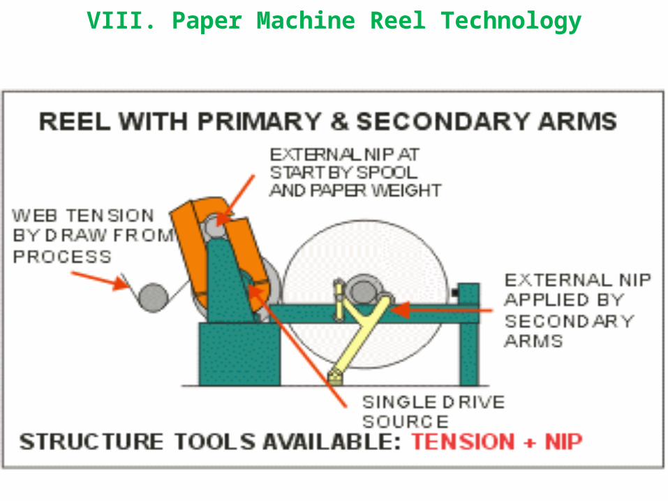
VIII. Paper Machine Reel Technology

VIII. Paper Machine Reel Technology

VIII. Paper Machine Reel TechnologyTHE CAUSE OF LAST SET DEFECTS
Why does such a condition exist from a reel that has served the paper industry so well? The basic design of the present reel dates back to the mid 1940s. The first installations were on newsprint paper machines and designed for a maximum 72" (1829mm) diameter jumbo, with machine speed of 1800 FPM (550 MPM) and a trim range of 200" (5080mm). The paper weight on the spool was in the range of 9 tons (8 metric tons).
Today the same basic concept using swing arms for secondary loading in place of the horizontal secondary cylinders is widely used on paper machines approaching 400" (10.1 M) reel trim and machine speeds in excess of 4500 FPM (1370 MPM). It is not uncommon to see reel spools supporting paper weight of 40 tons, (36 metric tons).

VIII. Paper Machine Reel Technology

VIII. Paper Machine Reel Technology
VIII. Paper Machine Reel TechnologyWhen winding shipping rolls on a paper machine winder it is universally accepted
that nip control is a significant factor when structuring a high quality shipping roll. The winder operator strives for a uniform transition in nip and roll hardness from the core to the OD of the winding set. Unfortunately, the geometry of a reel using primary arms does not lend itself to the precise nip control required for this uniform transition to optimize roll quality.
In normal reel operation the reel spool, at turn-up, contacts the reel drum somewhere near top center of the reel drum and immediately after turn-up, the primary arms rotate in a clockwise manner around the reel drum to the horizontal level rail. In this process, timing is important to insure the large jumbo winding on the level rails is moved horizontally on the rail towards the dry end to make space for the new reel spool being rotated to the level rails. In addition, when the reel spool arrives at the level rail position, the loading must be transferred from the primary to secondary arms. The transfer of load from the primary to secondary position is critical to attain a uniform nip.
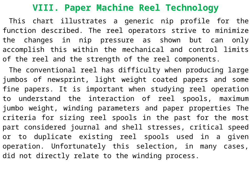
VIII. Paper Machine Reel TechnologyThis chart illustrates a generic nip profile for the function described. The reel
operators strive to minimize the changes in nip pressure as shown but can only accomplish this within the mechanical and control limits of the reel and the strength of the reel components.
The conventional reel has difficulty when producing large jumbos of newsprint, light weight coated papers and some fine papers. It is important when studying reel operation to understand the interaction of reel spools, maximum jumbo weight, winding parameters and paper properties The criteria for sizing reel spools in the past for the most part considered journal and shell stresses, critical speed or to duplicate existing reel spools used in a given operation. Unfortunately this selection, in many cases, did not directly relate to the winding process.

VIII. Paper Machine Reel Technology

VIII. Paper Machine Reel TechnologyThe reel is subject to the same laws of physics as other machines. In the process of
increasingly demanding application for the level rail reel, this fact may have been overlooked. In the case of the reel, the reel spool, reel drum and winding paper on the spool all deflect at different rates. How much these elements deflect is dependent upon the mass, the stiffness of elements and external loading. This chart indicates the varying deflection in cross machine elements of the reel. The reel drum itself is reasonably stiff as compared to the reel spool and winding paper
A result of the variation in deflection is a non-uniform nip profile between the winding drum and the roll, tight at the ends and light in the center.

VIII. Paper Machine Reel Technology

VIII. Paper Machine Reel TechnologyIn addition to the deflections caused by gravity reacting to the masses involved, the
mechanical operation of the reel introduces other forces that add to the complexity of the component deflections. A reel spool deflection component is present caused by the overhung primary hook loading at the time of turn-up through the primary arm movement to the load transfer in the secondary arms.
At the time the winding jumbo is transferred from the primary arms to the secondary rail, the secondary loading must be engaged before the primary arm loading is released. There is a time period when the two loadings are additive resulting in a spike in the nip profile unless the transfer of loading is performed in a smooth manner. The overhung load exerted by the secondary load system (in addition to the deflection caused by the primary arm loading) causes a horizontal deflection that couples with a vertical defection caused by the mass of the reel spool and winding paper complicating the issues.
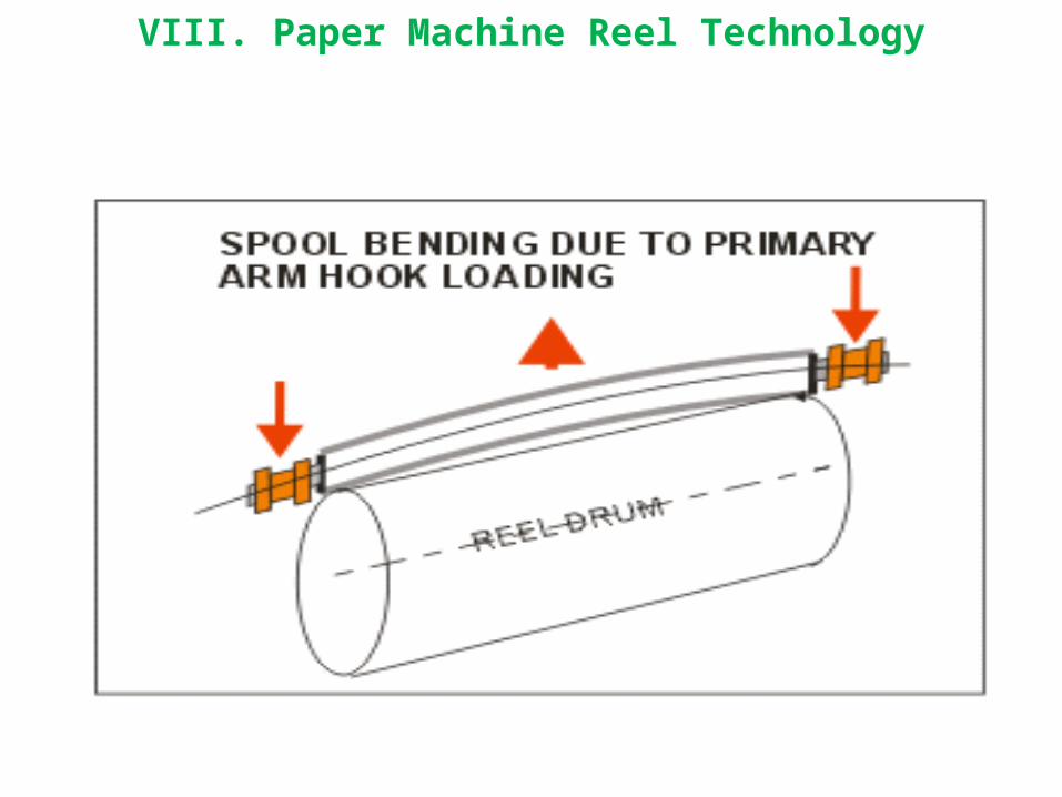
VIII. Paper Machine Reel Technology

VIII. Paper Machine Reel Technology

VIII. Paper Machine Reel TechnologyA & Z ROLL DEFECTS
This chart illustrates a vertical component of reel spool deflection. Paper mills that operate very wide paper machines discovered that if jumbos are stored for an extended period without being rotated, the jumbo will be difficult to process. This same deflection occurs while the jumbo is resting on the level rails during the winding process.
The above chart illustrates the paper being stressed due to the deflections during the reeling operation. As the winding paper rotates in a mass around the axis of the reel spool that is deflecting at a different rate than the paper being wound, stresses occur in the web at the 9 and 3 o'clock position at each end of the jumbo. This action is considered to be the cause of many of the defects in the A and Z rolls (front and back rolls) of the set off the winder.
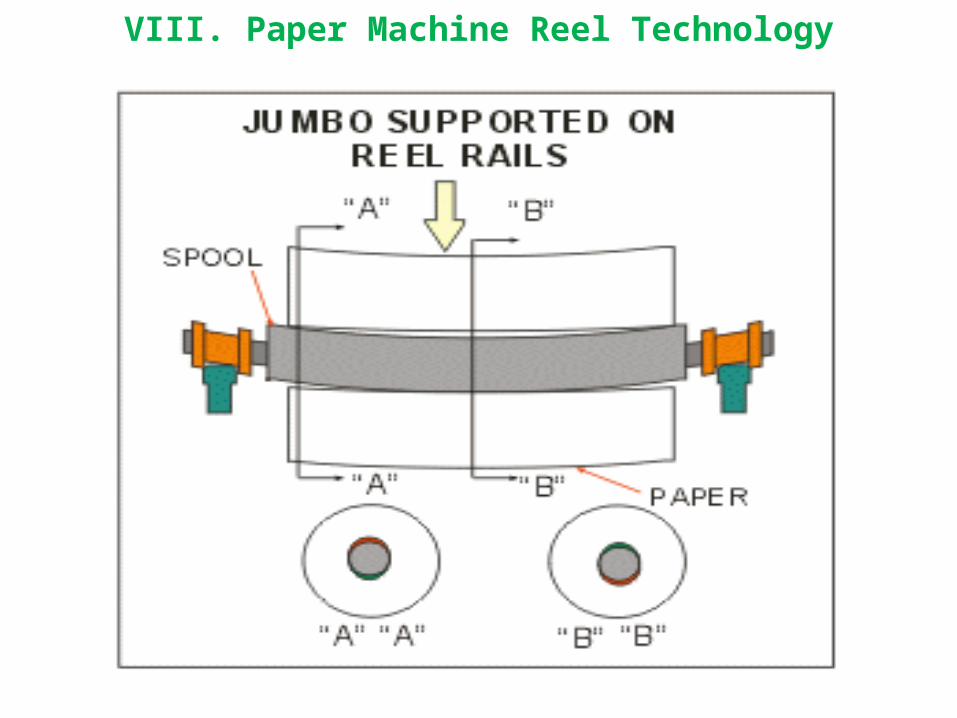
VIII. Paper Machine Reel Technology

VIII. Paper Machine Reel TechnologyTHE CHALLENGES OF ROLL BUILDING ON A REEL
Experience has taught us that left, on there own devices, winders will not make a shippable roll let alone a high quality shipping roll. Years of development in winding resulted in recognition of the mechanisms and controls required to produce a high quality shipping roll. In the case of a two-drum winder, the roll starts winding very soft and increases in hardness as the paperweight increases on the winder drums as represented by the red curve of the chart. Winder engineers and paper mills have developed a means to alter the hardness profile of the winding roll by carefully manipulating the TNT (tension-nip-torque) tools of winding.
This set of curves illustrates how back tension, rider roll nip and drive torque can be programmed to produce the most desirable wound roll for a two drum winder. There is also a recognition that as the "resultant" curve goes off scale, the limitation of the mechanics of the winder should be questioned and another mechanical mechanism should be considered such as an enhancement to the two drum winder or a duplex winder.
The machine reel presents the same challenge. The machine reel if nothing else is a continuous winder more likened to a duplex winder as opposed to a two drum winder. This chart attempts to portray the same scenario. The BLUE curve represents the nip profile of a standard primary arm reel. The GREEN curve represents the preferred nip profile. This preferred profile could possibly be attained with enhancements to the reel or in some case a replacement with one of the new generation reels.
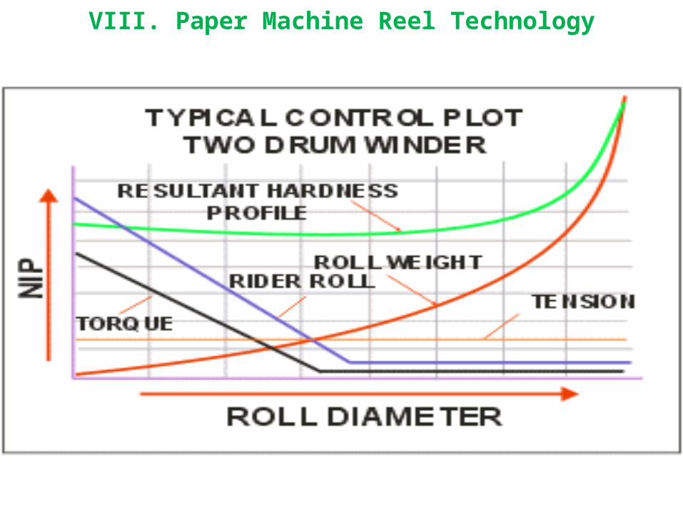
VIII. Paper Machine Reel Technology

VIII. Paper Machine Reel Technology
VIII. Paper Machine Reel TechnologyAVAILABLE MODIFICATIONS TO IMPROVE THE REELING PROCESS
In recognition of the need to improve the winding process on the paper machine reel, machinery builders have developed designs to attain higher quality jumbos with better runnability in subsequent processes. The paper mill can choose the feature that will give the best ROI consistent with their specific needs. A few of the improvements available are described. Due to the grade of paper, variations in sheet characteristics, vintage and original design of equipment, careful consideration must be given to insure the promised results can be attained.

VIII. Paper Machine Reel TechnologyPRIMARY ARM NIP RELIEVING
The weight of the reel spool at turn-up can induce high nip loads that are detrimental to the hardness profile. Equipment is available in the form of reel spool weight relieving to reduce the tendency of high nip loads at start. Additionally, some installations can benefit by replacing sliding friction with anti-friction ways that can produce more predictable relief and load results.
VIII. Paper Machine Reel TechnologyREEL CENTERWIND DRIVES
Torque control has become a standard feature of two drum winding and becoming increasingly popular with duplex winding. The success of centerwind drives on super-calendar windups has been proven in many installation. Rereeler installations are beginning to demonstrate significant operational improvement with the addition of centerwind drives. Reels are presently operating in the field equipped with primary and/or secondary centerwind drives and in some installations at both positions. Centerwind drives are proving to be a beneficial addition on reels although in some cases the ROI has yet to be justified. Centerwind drives on primary and secondary winding positions should be carefully considered as a viable tool to improve jumbo runnability.

VIII. Paper Machine Reel Technology

VIII. Paper Machine Reel TechnologyNEW TECHNOLOGY REELS
Builders are offering new designs to better serve the need for improved jumbo runnability and reel efficiency. A couple of new designs follow:
The Beloit TNT Reel. Some of the features described by the builder are:
1. Reel spool and winding jumbo are partially supported by the reel drum throughout the winding cycle.
2. The jumbo winds without transfers of nip loading or centerwind torque throughout the winding cycle.
3. Fully automatic operation with data logging, diagnostics and maintenance monitoring.
Picture and features from builder advertising literature.

VIII. Paper Machine Reel Technology

VIII. Paper Machine Reel TechnologyThe Valmet OptiReel. Some of the features described the builder are:
1. OptiReel increases mill's production and parent reel quality.
2. Eliminates broke and turn-up breaks.
3. Better runnability in downstream processes.
4. Larger parent reel diameters.
Pictures and features from builder advertising literature.
An additional new technology reel is the Beloit ATR (Advanced Tissue Reel). The ATR reel is similar in many respects to the TNT Reel , a major difference is a fixed position reel drum.
The descriptions and images of the new technology reels are from builders brochures and advertising literature. There are probably additional new design reels from other builders than those noted. Builders are encouraged to submit information suitable for inclusion in this article. Current designs may be greatly different from that shown. Check with machinery builders for current information as to availability and design.
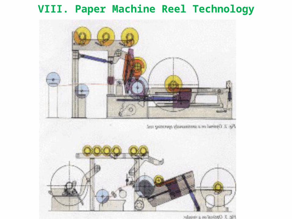
VIII. Paper Machine Reel Technology

VIII. Paper Machine Reel TechnologyOTHER REEL IMPROVEMENTS:• Programmed primary & secondary arm control systems. • "Bumpless" transfer control of nip and center wind drives.• Larger diameter reel spools. Reel drum surface-grooving and friction • Tension control systems • New turn-up devices. • Complete reel automation control packages.
• Smith, P., & Bagnato, L., 1993 TAPPI Finishing & Converting Conference Proceedings, "Relationship of the Paper machine Reel to the Winding Process"
• Frye, K.,TAPPI Journal, "Winding Variables and Their Effect on Roll Hardness".• Pfeiffer,D., TAPPI Journal, " Nip Forces and Their Effect on Wound Roll Hardness".• Frye, K.,1989 TAPPI Finishing & Converting Proceedings, "Runnability in the
Pressroom".• Roth, D., 1993 CPPA Conference Proceedings, "How to Build a Jumbo Roll and Other
Winding Tricks"• Dorfel, W., Papier Carton Cellulose, "Theory of Winding"• Daly, D., Paper Trade Journal, "Study of Defects in Wound Rolls lead to Better Winding
Control"• Bagnato, L., University of Maine, Summer Institute, 1996 "Paper Finishing & Winding"

IX. Building a Core Loading CartA core loading cart can be a means to make a 2 drum winder more efficient
from the time cycle standpoint if the winder is not presently equipped with an automatic core loading system. It is not uncommon, with good planning and crew training to reduce set change time by 45 to 60 seconds. On an average production winder, a good core loading cart operation can save an hour or more a day.
If the core loading cart is used properly, it can reduce the possibility of injury at the front aisle of the winder between the winder drums and roll discharge system particularly in nip related injuries.
The sketch shown shows the end view of the core loading cart. The width of the cart must accommodate the maximum number of cores used in a set. An open design will permit storing spare sets in the space below if it is left open.

IX. Building a Core Loading Cart

IX. Building a Core Loading CartA major concern when considering a core loading cart is the space at the
tending side of the winder between the winder side frame and the benchboard. The cart must be deep enough to handle the longest single core to be installed in the winder. Keep in mind that the core cart can be "rotated" into the winder if there is enough clearance to move the core loading extension into the winder at an angle and then align the cart to the winder drums when it clears the benchboard. In this instance it is necessary to use casters that can rotate 360 degrees.
If the cart cannot fit in this space, obviously the cart cannot be used unless the benchboard is relocated. If the benchboard does not interfere, and there is ample space, some mills use single direction casters and use a track in the floor to guide the cart into and out of the drum pocket. Design the track so it does not become a tripping area or injury can occur by turning an ankle.

IX. Building a Core Loading Cart

IX. Building a Core Loading CartAnother area that must be checked carefully is the space in the drum pocket and it's
relationship to the MAXIMUM core OD that will be used in the winder. The sketch at left shows a 40" diameter wound roll on a pair of 24" diameter winder drums. The brown core shown is 3 5/8" OD. The red core is a 6" OD and shows the core size limitation of this pocket. A cart of this type is used with fibre cores only, plain or tipped ends..
IX. Building a Core Loading CartWhen loading the cores, the core loading cart extension is aligned with the
valley formed by the two winder drums. The extension can be a simple "V" or if preferred, a curved member with a compatible radius to the core O. D. in use.
Note that the wound roll of paper is still in position on the winder drums. The cores are loaded BEFORE the wound roll is ejected from the winder but NOT BEFORE THE WINDER HAS COME TO A COMPLETE STOP. A complete stop means the winder drums are NO LONGER ROTATING. If the cores are pre-tapped, they can be positioned in a manner to stick to the tail of the set after the set is ejected. The crews must be trained to insure the wound roll will not be ejected until the cores are fully loaded and the operator responsible for loading the cores is completely clear of the area.

IX. Building a Core Loading Cart
IX. Building a Core Loading CartCORE LOADING SEQUENCE
Sequence 1
The cores are loaded in the core loader in the sequence they will be inserted in the winder, #1 core being the back side core and #6 the front side core. The core cart is positioned at the winder so the first core to be inserted is properly aligned. Design the core loading cart so it "bumps" up against a point on the winder to "register:" the same position on the drums each time the cores are loaded. The core loading extension is designed to just sit over the top of the winder drums. When the cores are pushed off the extension they will drop the very small vertical dimension to rest on the drums. This drop should be minimized in the design. Design the extension with the maximum trim width of the winder in mind.

IX. Building a Core Loading Cart

IX. Building a Core Loading CartSequence 2
THE INSERTION SEQUENCE: The cores are loaded into the winder in a sequence consistent with the slitter arrangement of the winder. Each core is pushed into the winder using the next subsequent core as the pusher tool to load the previous core. As an example, #2 is used to push #1, #3 is used to push #2, etc. In this manner, the operator inserting the cores can keep his hands and arms well away from the winder and out of harm's way. In the case of this sketch, core #1 is the back side core, cores #3 through #5 are intermediate cores and core #6 is the front side core. Core #6 has a special consideration for safety and is described in the next sketch.

IX. Building a Core Loading Cart
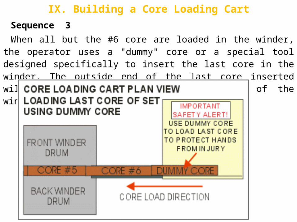
IX. Building a Core Loading CartSequence 3
When all but the #6 core are loaded in the winder, the operator uses a "dummy" core or a special tool designed specifically to insert the last core in the winder. The outside end of the last core inserted will be positioned inside the trim line of the winder.

IX. Building a Core Loading CartSAFETY NOTE:
Handling the last core to be loaded by hand places the operator's hand and arm at risk of injury if a malfunction or premature roll ejection were to take place. It is mandatory that a "dummy" core or other suitable pusher be used to insert the last core into the winder. The dummy core or pusher must be long enough to keep the operator well away from any possible pinch or nip point
After all the cores are loaded and properly positioned, the core loading cart removed, the mechanical elements properly positioned and interlocks satisfied, the wound roll can be ejected from the winder. The new tails are fastened to the cores, and the winder restarted to wind the next set of rolls.
While the new roll is winding, the new set of cores are placed on the core loading table to be ready for core loading for the next set to be wound.
Try to design the cart lightweight so it is easy to handle. With proper design, crew training and planning, a core loading cart can be a SAFE and USEFUL tool to advance the efficiency of the winding operation.