piping stress handbook - by victor helguero - part 2.pdf
TRANSCRIPT

Piping Stress
Handbook
Second Edition
-
-
Victor Helguero M.

Piping StressHandbook
Second Edition

Design Criteria for Pumps with SteelNozzles and Casings
API Code 610: Steel Pump Force,Moment, and Stress Limitations
The following criteria apply for pumps with 12-in. dis-charge nozzles or smaller. The forces contained herein areconsidered minimum criteria and should be adjustedwhere the vendor has experimental or test data permitting
Design Criteria for Allowable Loads'Moments, and Stresses
larger reactions. The vendor must submit comparable cri-teria for pump cases constructed of cast hon.
Suction and discharge nozzles should be designed towithstand forces and moments from the thermal expan-sion or contraction of prping. Piping reactions should becomputed in conformance with ANSI Code B31 . I orANSI Code 831.3 for pressure piping and should be de-signed within the limiting criteria set by this standard. Themodulus of elasticity must be adjusted for the operatingtemperature condition.
Each nozzle should be capable of withstanding doublethe forces and amounts listed in Table 8-1 applied simulta-
Table 8-1Nozzle Loadings
Fotce/ oment < 2Nomlnal Size ot Nozzle Flange (in.)
6810 12 14b '| 6D
Each top nozzleE
F, (compression)Fy (tension)F,
Each side nozzle
RFyF,
Each end nozzleF"F
F,Each nozzle
MrMyM"
160200100130
8501,100
530700
8507W
I,100
1,100700850
2,6N1,9001,300
t,2N1,500
7501,000
1,2001,0001,500
1,5001,0001,200
3,7002,8001,800
1,5001,800
9201,200
1,5001,zffiI ,800
1,800r,2w1,500
4,5003,4002,2W
2,0001,3001,600
4,7N3,5002,300
240 320 560300 400 700150 2W 350200 260 460
240 320 5602W 260 4ffi300 400 700
300 400 7002W 260 4@240 320 560
700 980 1,700530 740 1,300350 500 870
160130200
200130160
340260170
1,600 1,9002,000 2,3w1,000 1,2001,300 1,500
1,600 1,9001,300 1,5002,000 2,300
2,3001,500I,900
5,4004,0002,7W
M = Moneu ft-hJ = Verticalgo" to shaftz = Hoizontalgo' to shaJt
x = Axis parolzl to shaft
Reprcduced from Centritugal Pumps for ceneral Refinery Services, Suth Edition, 1981 , Standad 610 Table 2. Repinted courtes, of the Ameican PetroleumInstitute.
257

25A Piping Stress Handbook
neously to the pump through each nozzle, in addition tointernal pressure, without causing an hternal rub or ad-versely affecting the operation of the pumps or seal.
The baseplate and pedestal support assembly should beadequate to limit the shaft displacement, when measuredat the coupling, to a maximum of 0.005 in. in any direc-tion when subjected to the loads shown in Table 8-1.These loads represent the total effect of all external me-chanical forces that may be applied to a fully groutedpump base. They are to be applied to the pump throughthe suction and/or discharge nozzle (see Figure 8-1):
For purposes of evaluating computed piping-imposedexternal moments and forces, these forces be transferredfrom both suction and discharge flanges to the intersec-tion of the X, Y, and Z axes. An algebraic surffnationshould then be made for comparison with the moment lim-itation just given. The vendor should submit alternativecriteria for pumps larger than 12 in.
Because a particular nozzle on a pump will not alwaysbe subjected to the maximum allowable resultant forceand moment simultaneously, an increase in either the re-sultant applied force or the resultant applied moment maybe made if the following limitations can be satisfied at thatnozzle:.
(F"iF.) + (M^/M.) < 2, F"/F, < 2, and M"/M. ( C
where C
M"
E
M.F,D
: 2, for nozzles 6 in. and smaller= (D + 6)/D, for nozzles 8 in. and larger= resultant applied moment at the nozzle, ft-
lb= resultant applied force at the nozzle, lb: resultant moment (from Table 8-2), ft-lb: resultant force (from Table 8-2) lb= nominal diameter of nozzle flange. in.
The resultant applied force or moment may be in-creased up to double the values in Table 8-2 if the maxi-mum combined limit on the installed equipment is not ex-ceeded. This limit is determined by the summation of theforces and moments from Table 8-2 on both nozzles si-multaneously, taken about a point defined by the intersec-tion of the axis of the shaft and the centerline of the pedes-tals.
For heavy-duty baseplates the total applied resultantforces and moments on the suction and discharge nozzlesshould not be more than twice the eouivalent of thosegiven in Thble 8-1. For applied resultant forces and mo-ments that are greater than these, allowable values shallbe mutually agreed upon by the purchaser and the vendor.
Design Criteria for Pumps with Cast lronor Aluminum Nozzles and Casings
Aluminum Pump Force, Moment, andStress Limitations
The following criteria apply for pumps with 4-in. orsmaller discharge nozzles (suction nozzles may be larger).The forces contained herein are considered minimum cri-teria and should be adjusted where the vendor has experi-mental or test data permitting larger reactions.
Suction and discharge nozzles should be designed towithstand forces and moments from the thermal expan-sion or contraction of piping. Piping reactions shall becomputed in conformance with the petroleum refinerypiping code for pressure piping ANSI Code 831.3, Sec-tion 319, and should be designed within the limiting crite-ria set by this standard. The modulus of elasticity shouldbe adjusted for the operating temperature condition.
Table 8-2Suggested Allowable Resullant
Forces and Momenis(For Vendor's Standard Baseplates)
E io^-de.. ResultantForce/Moment
Nominal Size of Nozzle Flange (in.)23 4 6 810 124
430690
FM.
640 860 1,5001,400 2,000 3,500
2,300 2,',700 2,9005,200 6,600 8,200Figure 8-1. Pump coordinate system.

Design Criteria for Allowable Loads, Moments, and Stresses 259
Limit tension and comDression forces to 500 lbEach nozde should be capable of withstanding forcesfrom external piping determined by the following formu-Ias:
. Suction nozzles:
F"(1.6w(50Dr Discharge nozzles:
F,6 ( (2w - F.,) < 50D
o Top suction and top discharge nozzles are further lim-ited by:
F.. and F,.a : (Fx2 + Fz2)L/'z
and for suction nozzles
F*(1.3w(40DFr" (in compression) ( 1.2w ( 50DFr, (in tension) ( 25DF",(w(35D
and for discharge nozzles
F*a ( (1.8w r F*) <Fra (in compression) (Fra (in tension) ( 0.5w
< 50D
F,a((wtF,,)<35D
o End suction and top discharge pumps are further limitedby:
F": G^'?+Fy.)-
and
F,6: (Fl + F"a'?)"'
and for suction nozzles
and for discharge nozzles
F"a((1.8wtF*)<40DFra (in compression) ( 2w + Fy. < 50DFra (in tension) ( 0.5w ( 25DF.a((w1F".)935D
where Fr
Force, lbResultant of forcesAxis parallel to shaftVertical 90' to shaftHorizontal 90' to shaftWeight of pump only, lbDiameter, nominal diameterDischarge or exhaustSuction or intake
F. is the resultant shear force in the plane of any specificflange face.
Each suction and discharge nozzle should be designedto withstand the forces described for the specific configu-ration. Unit stresses in each nozzle should be limited to:one-third of the allowable hot stresses for pipe sizes ( 4in.; one-half of the allowable hot stresses for pipe sizes> 4 in.; as shown in ANSI Codes B31.1 and 831.3.
The baseplate and pedestal support assembly on pumpshaving a discharge nozzle of 4 in. should be adequate tolimit the shaft displacement, when measured at the cou-pling, to a maximum of 0.005 in. in any direction whensubjected to the following loads. These loads represent thetot;l effect of all externil mechanical forces tliat may be
applied to a ful1y grouted pump base. They are to be ap-
plied to the pump through the suction andior dischargenozzle.
M, : 3.0 W* ftlbMv : 2.0 wx ftlbMz = 1.5 W+ ft-lbM* : Moment in Y-Z planeMy : Moment in X-Z PlaneM, : Moment in X-Y planeW : Weight of pump only, lb
For purpose of evaluating computed piping-imposedexternal moments and forces, they should be transferredfrom both suction and discharge flanges to the intersec-tion of the X, Y and Z axes. An algebraic summationshould then be made for comparison with the moment lim-itation just given.
The vendor must submit alternative criteria for pumps
having a discharge flange of 4 in. NPS. It is suggested
that these criteria be developed as a result of tests'
X
vzwDdS
40D(2w t Fr")< 25D
F".(1.2w(50DFr.(0.6w(35DF.,< w(40D
* Minimum W is 500 lb in tlpse computations.

260 Piping Stress Handbook
Design Criteria for Turbine Drivers withSteel Nozzles and Casings
Steel Turbines Force, Moment, andStress Limitations
At the operating temperature, using the hot modulus"E," resultant bending moments are permissible up to avalue that would cause a bending stress of S5/4 in a con-nection having a section modulus equal to the connectingpiping for the same size where the comection is 4 in. IpSor larger. On smaller size connections a stress of S"/3 ispermitted. (56 is as defined by ANSI Code 83l . I or ANSICode B31.3 (current issue) for the material of construc-non. )
The resultant shear force at the face of the flanee andany individual component may not exceed 2,000 lb. Theresultant forces and individual components are limitedfurther as follows:
o Individual comDonents:
o Resultant components:
Algebraic summation of F." ( 1.6wAlgebraic surnmation of Fo ( wAlgebraic summation of F,' ( l.6w
r Combined resultant:
(F.*), + F.y, + F-r)'" ( 2w
Use up to 100% cold spring and satisfl the operaringcondition only.The total resultant force and total resultant moment im-
posed on the turbine at any connection must not exceedthe following:
(s0oD" - M)
where F : Resultant force (lb), including pressureforces where unrestrained exoansionjoints are used at the connection. excepton vertical exhausts
M : Resultant moment, ftlb
D. : Pipe size of the connection (IpS) up to gin. in diameter. For sizes greater than thisuse Dc : (16 + IpS)/3 in.
The combined resultants of the forces and moments ofthe inlets, extraction, and exlaust connections, resolved atthe centerlines of the exhaust connection and shaft mustnot exceed the following two conditions:
(2s0 D. - M.)
where F, : Combined resultant of inlet. extraction.and exhaust forces, lb
M, : Combined resultant of inlet, extraction,and exhaust moments and moments re-sulting from forces, ftJb
D. : Diameter (in.) of a circular opening equalto the total areas of the inlet, extractionand exhaust openings up to a value of 9in. in diameter. For values beyond this,use D. : (i8 * equivalent diameter)/3ln.
Components of these resultants should not exceed:
< 50 D., M_ <250D,< 125 D., My. < 125D.< 100 D., M., < 125D.
Vertical Exhaust Connection
For installation of turbines with a vertical exhaust andan umestrained expansion joint at the exhaust, an addi-tional amount of force caused by pressure loading isallowed. (The additional force referred to is perpendicu-lar to the face of the exhaust flange and central.) For thistype ofapplication, calculate the vertical force componenton the exhaust connection, excluding pressure loading,and compare with the value of t/o the pressure loading onthe exlaust. Use the larger of these two numbers for avertical force component on exhaust connections in mak-ing the calculations just outlined.
The force caused by the pressure loading on the exhaustis allowed in addition to the values established bv the Dre-ceding up to a maximum value of vertical force (ib) o; theexhaust connection (including pressure loading) of 151/:times the exhaust area (in.2).
These values of allowable force and moment Dertain tothe turbine structure only. They do not pertain to theforces and moments in the cormecting piping, flange, and
F.
F-<F(F,<
1.3w ( 160D.6w ( 130D
w ( 160DF."F'vrF

Design Criteria for Allowable Loads, Moments, and Stresses 261
flange bolting that should not exceed the allowable stress
as defined by applicable codes and regulatory bodies. (See
Figure 8-2.)
Design Criteria for Turbine Drivers withCast lron or Aluminum Nozzles and
Casings
Cast lron or Aluminum Turbine Force,Moment and Stress Limitations
At the operating temperature, using the hot modulus"8," resultant bending moments are permissible up to avalue which would cause a bending stress of 56/4 in a con-nection having a section modulus equal to the connectingpiping for the same size where the connection is 4 in. IPS
or larger. On smaller size connections a stress of Sr,/3 is
permitted. (56 is as defined by ANSI Code B3l. 1 or ANSICode 831.3 (current issue) for the material of construc-tlon.)
The resultant shear force at the face of the flange andanv individual component should not exceed 500 lb. The
RIGHT ANGLE TOTURBINE SHAFT-
/
resultant forces and individual components will be limitedfurther as follows:
o Individual components:
. Resultant components:
Algebraic summation of F,* ( 1.6wAlgebraic summation of Fo ( wAlgebraic summation of F'" ( 1.6w
. Combined resultant:
(F*2+F,r2+F''?),n<2w
Use cold spring, but comply to these limitations in bothoperating and installed conditions.
The total resultant force and total resultant moment im-posed on the turbine at any connection must not exceed
the following:
F< (s00D. - M)
where F = Resultant force (lb), including pressure
forces where unrestrained expansionjoints are used at the comection, excepton vertical exhaustsResultant moment, ft-lbPipe size of the connection (IPS) up to anS-in. diameter. For sizes greater than thisuse a D" : (16 + IPS)/3 in.
The combined resultants of the forces and moments ofthe inlet. extraction, and exhaust connections, resolved at
the centerlines of the exhaust connections must not exceed
the following two conditions.
l.F.< (2s0 D. - M)
F"(1.3w(40DFr(.6w(35DF"< w(40D
M:D":
where F. :
M,:
Combined resultant of inlet, extrac-tion, and exhaust forces, lbCombined resultant of inlet, extrac-tion, and exhaust moments and mo-ments resulting from forces, ft-lbFigure 8-2. Turbine coordinate system.

Design Criteria for Compressors withSteel Nozzles and Casings
Moment, and Stress Limitations
At the operating temperature, using the hot modulus"8," resultant bending moments are permissible up to avalue that would cause a bending stress of $,/4 in a con-nection having a section modulus equal to the comectingpiping for the same size where the connection is 4 in. IPSor larger. On smaller-size comections a stress of S1/3 ispermitted. (S1 is as defined by ANSI Code B31.1 or ANSICode 831.3 (current issue) for the material of construc-tion.)
The resultant shear force at the face of the flanee andany individual component should not exceed 2,60 lb.The resultant forces and individual components will belimited further as follows:
r Individual components:
. Resultant components:
Algebraic summation of FoAlgebraic summation of FoAlgebraic summation of F-
Centrifugal Steel Compressor Force,
< 160D< l30D< 160D
o Combined resultant:
(F*2+Fry2+F.z;rnE2*
Use 100% cold spring and satisf the operating condition only.
The total resultant force ald total resultant moment im-posed on the compressor at any comection must not ex-ceed the following:
F< (925D. - M)
where F =
J
Resultant force (lb), including pressureforces where unrestrained expanstonjoints are used at the connection.Resultant moment, ftlbPipe size of the connection (IPS) up to 8inches in diameter. For sizes greater thanthis use D" : (16 + IPS)/3 in.
(463 D. - M.)
262 Piping Stress Handbook
D. : Diameter (in.) of a circular openingequal to the total areas of the inlet,extraction, and exhaust openings upto a value of 9 in. in diameter. Forvalues beyond this, use D.(18 + equivalent diameter)/3 in.
Components of these resultants should not exceed:2.
F* 50 D., < M* < 250 D.Fy. 125 D., < My. < 125 D,F". 100 D,, < M". < 125 D,
M:D:
The combined resultants of the forces and moments ofthe suction interstage and discharge connections, resolvedat the centerlines of the discharge comection must not ex-ceed the followins two conditions.
1.F.<
where F. :
MI:
Combined resultant of suction, inter-stage and discharge forces, lbCombined resultant of suction, inter-stage and discharge moments result-ing from forces, ftlbDiameter (in.) of a circular openingequal to the total areas of the suc-tion, interstage, and discharge open-ings up to a value of 9 in. in diame-ter. For values beyond this, use D,= (18 + equivalent diamerer)/3 in.
F* ( 1.3wF, ( .6wF" ( 1.0w
2. Components of these resultants should not exceed:
F," < 92 D., M_ < 460 D,Fy. < 230 D,, My. < 230 D,F,, < r85 D,. M. < 230 D,
l.6w
1.6w

Design Criteria for Allowable Loads, Moments, and Stresses
Design Criteria for Compressors withCast lron or Aluminum Nozzles and
Casings
Cast lron Compressor Force, Moment,and Stress Limitations
At the operating temperature, using the hot modulus,"E," resultant bending moments are permissible up to avalue that would cause a bending stress of S;/4 in a con-nection having a section modulus equal to tle connectingpiping for the same size where the connection is 4 in. IPS
or larger. On smaller-size connections a stress of 56/3 ispermitted. (Sr is defined by ANSI Code 831.1 or ANSICode 831.3 (current issue) for the material of construc-hon.)
The resultant shear force at the face of the flange and
any individual component shall not exceed 500 lb. The re-sultant forces and individual components are limited fur-ther as follows :
o Individual comDonents:
. Resultant components:
Algebraic summation of F* (Algebraic summation of Fo (Algebraic summation of F," <
o Combined resultant:
(F*2+F.y2+F-'?)'n<2w
1.6w1.0w1.6w
Use cold spring, but comply to these limitations in bothoperating and installed conditions.
The total resultant force and total resultant moment im-posed on the turbine at any connection must not exceedthe followins:
F.(1.3w(40DFr(.6w(35DF"< w(40D
where F : Resultant force (lb), including pressure
forces where unrestrained e xpansionjoints are used at the connection. except
on vertical exhaustsM = Resultant moment, ft-lbD" : Pipe size of the connection (IPS) up to 8
in. in diameter. For sizes greater than thisuse a D" : (16 + IPS)/3 in.
The combined resultants of the forces and moments ofthe inlet, extraction, and exhaust connections, resoived at
the centerlines of the exhaust connection must not exceed
the followine two conditions.
1.F.< (250 D. - MJ
where F. : Combined resultant of suction, in-terstage and discharge forces, lb
M. = Combined resultant of suction, in-terstage, and discharge forces, lb
D, : Diameter (in.) of a circular openingeoual to the total areas of the suc-tion, interstage, and discharge open-ings up to a vaiue of 9 in. in diame-ter. For values beyond this use D,= (18 + equivalent diameter)/3 in.
2. ComDonents of these resultants should not exceed:
< 460 D.< 230 D,< 230 D,
F." < 92 D., M,-F.y < 230 D., M.yF. < 185 D., M-
API Code 661 Design Criteria forAir-Cooled Heat Exchangers
Each nozzle in the corroded condition must be capableof withstanding the moments and forces defined in Table8-3.
The design of each fixed header, of the fixed header tosideframe connection, and of other support membersshould be such that no damage will occur due to the simul-F< (s00D" - M)

IvI,M,M-Moments. ftlb Forces. lb
3,000 4,000 2,000F,FyF"r,500 3,000 2,500
This recogrrizes that the application of th€s€ moments andforces will cause movement and that this movement willtend to reduce the actual lmds.
Tabte &3Allowable External Forces and iloments tor
Air-Cooled Heat Exchangers
NozzleSlze, NPS Moments ft-lbInches ilr lily M:
264 Piping Stress Handbook
taneous application of the following design iotal nozzleloadings on a single header:
For the direction of loads see Figure 8-3.The total of all nozzle loads on one multibundle bav
should not exceed three times that allowed for a singliheader.
The maxirrum allowable moments and forces for float-irlg headers are a matter of agre€ment between the pur-chaser and the vendor.
Figure 8-3, The direction of the loads defined in Table &3. Reproduced lrcm Air-Cooled Heat Exchangers forGeneral Refinery Se/.v,bes, Second Edition, i978, Stan-dard 661, Figure L Reprinted courtesy of the AmericanPetroleum Instilute.
Forces, lbF, F,, F2
lth2
68
10t214
50 70 5070 120 70
200 300 2N400 600 400
1,050 1,500 8001,500 3,000 1,1002,W0 3,m0 1,2502,5W 3,000 1,5003,000 3,500 1,750
100 150 100150 2ffi 150300 250 300500 400 500600 750 750850 2,000 1,200
1,000 2,000 1,5001,250 2,W 2,0001,500 2,500 2,500

can readily be seen that the smaller expansion will deflectthe longer leg more easily than the larger expansion willthe shorter leg.
To develop Tables 9-1 and 9-2, a guided cantilever for-mula has been used to calculate stresses. If we observeour Example Problem 9-1 for an expansion ofX = -92in., the required offset is about 13 ft for a stress of 15,000psi (See Thble 9-1) and 23 ft for a stress of 5,000 psi (SeeTable 9-2). If Point A is attached to a piece of rotatingequipment, you will need to have about 23 ft to make thesystem more flexible. If the system is attached to a pieceof nonrotating equipment, a 13-ft offset will be sufficient.
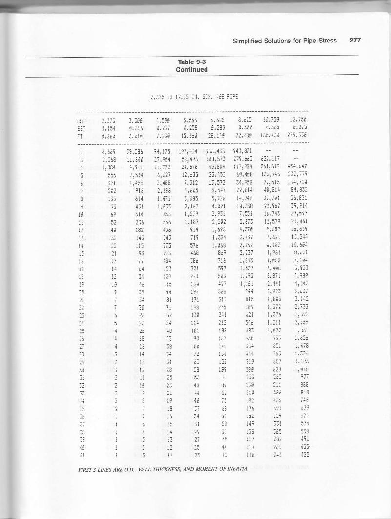
To find the thermal forces Table 9-3 is to be used, whichshows forces for a unit reflection with various leneths ofoffset.
Note that in identifuing pipe sizes the tables show wallthickness and moment of inertia as well as O.D. All forcesare calculated from the formula:
F : 6 Ell1728 L3 (guided cantilever)
where F : Force, lb {: E O-.ton, t tn.,E = Young's modulus of elasticity, (30 x 106
psi)I : Moment of inertia of pipe, in.aL : Length of the shorter leg, ft
I Fys = 434lbI
F.B = 6,949lb.
Simptified Solutions for Pipe Stress
These tables are developed as a tool for the piping stressengineer or the piping designer by which he can quicklyevaluate a proposed layout before he proceeds with his de-slgn worK.
It is important for the reader to understand that the ta-bles presented herein do not compose a rigorous solutionto the pipe stress problem. Computer calculations must bemade for borderline cases. The tables are approximatevalues onlv for two-anchor oroblems.
Example Problem 9-1
Consider the piping arrangement in Figure 9-1.
Size: 8 in.Schedule: Sch 40Material: A-53 Grade B
O.D.: 8.625 in.Temperature: 600'F
Coefficient of thermal expansion: .046 in./ft
The expansion for the 20-ft leg is X : .92 in., and theexpansion for the 10-ft is X = .46 in. By inspection, it
Figure 9-1. Diagram for Example Problem 9-1 .
265
(Text continued on page 291.)

256 Piping Stress Handbook
Table 9-1Lengths ot Offset Required to Safely Absorb Various Expansions tor Piping Between Two Solld Anchors
(Stress Limit is 15,000 pst)
Pipe O.D. tength (ft) Bequired to Absorb Expansion A (in.)(in.) ol 0.80.3 0.4o.2 0.5 0.6 o.7 0.9 1.0 1.1 1.21.31.92.3
4.5
6.6l'.D
rs .7
74.916,S18 .02g .g24.530 .s36 .g42,94A.S54.9
1.5
2,63.53.3
4.2
5.15.35.75.16.47.97.8
9.3
tg .5
2.3
3.0
4.3
5.25.96.6
7.68.18.59.19.9
l1,l
t4.lI4.9
3.4
4.65.2
5.il
8.18.9
9.910 .511.1
tJ.ol4 .9r6.lu.318.3
3.94,3
5.16.77.48.49,4
rg .216 .7
t2 ,212.at4.lIE ?
17.318 .5
2L.I
3.64.44.86.55.8
9.410.5IL.412 .gt2.a
l4 .4
!7,6
2g ,8
23 .6
4.8
6.67.48.29.0
l0 .3
12,513.214 .l14 .915.717 .3l9 .32t .722.A
5,2
?18.58.9
11.1L2.4IJ.514.2
15.1L7 .St8.52g .822 .8
26 .428.0
4.6
6.1
8.6
rs .4lr.:t
l4 .515 .216.317.3t8 .2
22 .324 .426 .428 .229 .9
4.9
8.99.1
tg ,rtl.l12,6l4 .1
16.1
27 .r23,625 .928.929 .9
6.25.9
t0.6lt.714.916.2L7 .g18.2l9 .326 .322 .324.9
29 ,s
JJ.5
5,46.57.28.9
7S .lLt.212.214,915.6r7 .017.8
2S ,2
23.426 .728.639,933.1
6,8
9.310.51',t tI2 .814 .5
17.8l8 .6
2L .T22,324.427 .3
34.5
.8 4. .3
Pipe O.D. tength (ft) Required to Absorb Expansion A (in.)(in.) -r-:3 2.9 2.5 3,0 4.5 5.9 6.6 6.5 7,01.31.92.3
IS .1
74.0L6 .Ol8 .026,024,93g .g36 .S42 .048,954.5
8.4ro ,411.8L3 .g14.316.3L8 ,219 ,92g .822.323.624.9
Jt.5
36.138,54r,s
u.d9.7
12.o13.615.115 .5l8 .92I.022.924 .T
27 .329.8
38.6
44.647 .3
9.910.913.4L5.2l5 .9l8 .521.123 .525.626 .928.830.532.2
3 9.443 .2a6 .749 .9a2.9
9.9l0 .811.9
.l o.520 .223 .rza .628 .l29.5
38.643 .247 .351.154.75A.g
9,7
12.915.9I8 .g26 .g2L .925 .027 .935,431.934.136.1JO.I4r .746 .751.155.259,162.6
tg ,4
13.817 ,g
2I.323 .4
29 .8
36 .438,54g .744.649.954.7
53.167 .S
11.0t3.314 .678,526.5
24 .8
3r,534.436.1
43.247 .3
58,6
67 .S7t.s
ll.5!4 .615 .4t9 .62I .623 ,9
29 ,9
36,3JU.I4S ,'l
45.649.9
51.166 ,O70.67 4,9
L2,
2g .022 .625 .g27 .431 .334.9
4S .642 .145.347.852 ,35 8.664.1
7 4.I
16.929.823 ,626 .L28 .6
4I.7
47 .349 .954.761.t67,9
a2.6
13 ,2L6 .gI7 .6
24.6
34 .638 .S41.443.546.549,352 ,Ss5 .963.6
8S ,5
16.518 .222.5
28 ,239.9
39 .443 .s45,148.2sl.153 .9
55,0
?a I
88.5

Simolified Solutions for Pipe Stress 267
Table 9-2
Lengths of Oftset Required to Safely Absorb Various Expansions tor Piping Connected to RotatingEquipment (Stress Limit is 5,000 psi)
Pipe O.D. Length (ft) Required to Absorb Expansion A (in')(in.) -6:i o.2 0.3 0.4 0.5 0.6 o.7 0.8 0., 1.0 1.1 1.2
t.9 3.4
3,5 4.6
6,6 5.48.6 7.3
ro.7 8.rr2.7 8.974.s 9.3L6.0 9,9t8,0 I0,528 .0 1t.r24 ,O 12.230 .o 13,536.s L4.942.A 15.148.0 L7 .354,6 18.3
4.9 4.94.8 5.9
6,6 8,97 .4 9,r8.2 t0.r9,9 1r.1
r0.3 12.6
12.5 15.4t3,2 16.r
14.9 18.3
r7.3 27,r19.3 23.621.1 25,922.8 28.924.4 29.925 ,9 31.7
9,3 70,4L6 .5 1r .811.7 13.012.8 14.314 .6 16 ,316.3 L8.2L7.8 19.918.6 2q .819.9 22.32r ,r 23.622.3 24.924.4 27 ,327.3 3 0.529 .9 33 .5
34.6 38.636 ,7 4L.0
6.98.4
11 .4L2.914 .315 .7
20 .02r .8
24.425 .927 ,329.9
36 .739.642 .344.9
7.5
rg .0
74,0r5,416.9lo I2r.6
24,7
28 .029.532 ,3
39.6
48.5
8.0
10 .7
l6 .5r8.t20 .7
26 .4
34,638.6
45 .748.9
8.t76.11t .3r4.0t5 .817 .519.2
24.5
28 .g
47 .A44,948,5
55 ,g
9.0l0 .811,914.7
26.223 .r28,129.5
38.643.247 ,35I .I58.0
9,4 9.8tr .4 11 .9
15 .4 16 .1
r 9.4 29.2
24.2 25,3
29.5 36,830 .9 32.333 .l 34.6
37 .6 3 8,540.5 42,3
49.7 sl .953 .6 56 .057.3 59 .960,8 6 3.5
Pipe O.D. Length (ft) Required to Absorb Expansion A (in.)(in.) i.s 2.O 2.5 3.0 4,9 4.5 5.0 6.q 7.9
1.3 rl .01.9 13.32.3 14,63.5 18.04.5 29.5
8.6 24,3ls.7 31.6L2.7 34.414.0 36,LL6.0 3 8.518.0 4L.O26.9 43.224.6 47 .330 ,0 52.936 .0 5a.S42.O 62.648.5 67.054.9 7 r.g
15.9 18 .920.8 23.323.6 26,426 .L 29.228.6 32,0
36,5 4q.83 9,8 44.54r,7 46 .744,6 49 ,947.3 52.949,9 5s.854.7 61.r61..1 68.467.9 7 4.972.3 89.977 .3 85.582.O 91.7
15.6 16 .818.8 26 .320 ,7 22,425,5 27 .629.s 31.332.0 3 4 .6
4g.r 43.344 .'t 48.348.'t 52.6Fl I q(
'54.7 59 .r58 .0 62.661, t 66.067 .0 72.374,9 8q.982 .S 88.688.6 95.794 .7 r02.3
109.5 rsg.5
18 .0
29.5
37.949,546 .3
61 ,070.6
86.5
L02.3L09.4116.0
23,g25 ,4
43,549.r54,8
62.667 .077.074,982 .09r.7
L00.5108.5rt6,g123.1
20.L24.3
33.037 ,44t .445.351.7
65.0
74.97 8.985,5
ro5 .9114 .4r22 .3L29 .7
21.1
28 .g34.639.243 .441 ,5
66 ,566.9
74.L78,582,890.7
I6L,4ItL.rr2g ,o
r36.1
22,926.6
35,r4t,045.349 .756 ,763.268.972.377 .3a2.g85,594 ,7
10s.91r5.0125,3134,0I42.I
22.927 .7
42 .7
59.065.8
80.5
96.098 .6
110 .3I2A .a130.5139 .5L4't,9
23 .828 .83t ,539.6
49 .0
78.r
88.693 .4
IO2 .3]f 4.4r25.3135.4L44.7

Piping Stress Handbook
Table 9.3Force (lb/ln.) ot Expansion tor L-Shaped pipe (No Etbow)
?.375 i0 12.;5 i . sc!.i. 5s PIPE
{IFF-
FI
l. J/J J.lt0,,t65 !.SS3t.3ls !,3sc
4,5S9 5.563 ii,6:5 !.6?5 lS.;Ss l3,ig$g,gs3 0.1t9 g.lr9 0,lg? Lt3{ 9.156?.8tt 6.?4t ll.84t ?6,{{t 6?.?6S t22.iAF
i
J
5
6
tI7
LE
l3
IE
t,
?3
:5r62i:s?t;tli3rll34
lgt7:€3t
4! 190 t6!94: Ig!586 99t457 t5{!!3? 344!?74 8l?r9fi9l,!li 5,5?t l$.849 ?iigg? tf,7r5 tEi,BE1, ?4t,t3E i?f.lgg5t3 :!rtB 1.573 l!!td7 t9,t8g 4Jtt34 19?,486 199:?t l:6? t!98{ :!3,11 5!789 ?,87! ?!rfi{ 52,4?3 lS!!991i52 ,i2? I.353 3,35t 5!7lz 1?!751 3g!5i6 t9,62?9$ 3t55{ 165
45 t8sJ3 136
?5 t9i19 ?n
15 6?
!l {trfl 45
tE? ?64
s7 4
853 ?! ltg .3,19i 9,F35 l9! t23 37,16957? lr,ll3 7,418 :!17? lt,gu Z4Jrg{9t 993 l,i9l 3,778 8!997 17,{8FftJ 724 l,?3{ :,;5,1 6!3:l l2r?{9275 5{1 121 ?,989 {!9?8 9,578169 4t9 714 11594 J.?96 7,378t33 32t 55t I,I5{ 2!985 5,803
E 31 7r i7 3gr 672 r.6tt J.lr37 t9 69 147 tst 561 t!t35 2.3956 ?l 5i t?4 2l? 47i I,tIs ?.i865 ts,4t7
43 166 lsg 49: 956 1!85999 t5{ 344 g?t t.59{75 133 7i7 7$8 t,37768 116 f59 616 l!.1t7
41532JTJiI
l tl 1{?l{:i
1i'E!t
l6l]3]!if!lgI 5 ll tir5t5:4l4r|2l4E?S
45t l!fs{ ?!399 {.i{63AA 816 l!t{t 3t717
?2t 519 lr|4gi99 4r4 ?:!
5t i'l3l E9
9 f9 46 i! l7S 426 Bt6t I l7 4! ;t i57 l7I
5J i1S 333 64S
5i lr5 29C 5gl:l ll3 ;&9 5!54$ tfz ?4t 47?
rit 428
:ss 189
lst 355
7i8tl137ti;?I 3 .6 :5 :i
s l{ ?4 54 1?9 25?
5 iJ ri :g t:s :r-!
4l f::d €4
iE l6i S?4
64 153 297
5? l4r :713
7
I
tr!g
i 5 l2 :i? 5 it It
,iii lll 113
43 19M9l, !€ 4s 95 lB5
FIRST 3 UNES ARE O.D., WAIL TEICKNESS, AND MOMENT OF NERNA.

Simplitied Solutions for Pipe Stress
Table 9-3Contlnued
i,l TE 3t $1. scH. :3 PllE
7!l
lq,Ei'd l i, dtit iS,S{0il. !5i S,169 6' lis
i6:.:iF 1*3.14F 167.it!
:4. BSS 3il, tCg
$,?lu 8.258
1151.5?f ?5S5.196
s. i38374.tlt
3
i
lit?1li4iJlit7
l9
:iii23
it2t!i17
?2
:9
3iti-rl1T
;:l631
t8i1
4i4;
:3, [7{ 53.5;7 i4.i95:t,;19 37.6:t 5!!i?lii..934 :7.,l]: lB!:94i?,773 !g! $ld 28,771
I,dSF 15.S75 ?:! lgli.7s8 l:!48i 17, iJgi, i7t 9!99t ll! 955
:r017 8. !3S ! 1,1-4S
4,134 n!i?7 9,339
I,{47 5,5ii 7.,;l{?!994 4,ifr4 6!3,t6
!!1Ji 3!9t9 5,591
:! l17 3,4?9 4,787
I, E?9 :.9&? ,l! 13:
1. s9S :,:?S 3,5?6
1,39? ?! ?55 I,l{?I,:?5 1,9S4 lt1ifil,+ts4 11756 1,431
953 1,561 i,179E&9 i,l?4 l,!46i1L 1, t5$ 1,744
694 1r 1?5 1!5?g
i?7 1,4i6 l.4lB5,:S t:t l!:8551; 137 L ii?471 r6t 1, 16S
l]t 69s 9I{t?5 i4g 493
liJ f,Ed ldl$4 347 i5&
lr9 rs6 ilg!85 46? 614
1s5 4lt 5!S
;,ii' 39S 55$
?2t 1i& :t7il-l 145 +sl19? lt: 45S
IBe lEl 4f i6
174 !S: .rtl161 ?$4 lig
tI4r:9: 3?5,9S7
164!551 199,396
11?,95? 169,l9il9gt l16 ?g?,l!269, q?6. 135,8:954!i$l 1fl.:7r4J,71,5 9B! liE35!543 i9,79fi:9.?g$ .65.745
!{!416 34! gil:t!569 4A.l?5
lt.4s9 19! ?6tin oEE i?'i,lt
t?!t53 7',g7B! 1-!61 23,798
I,gii ?2,l3Ig!677 1?.4i97,b77 il!?356, B?: 15,Jlli,st4 lStE?l!.4$5 1?,:t74!il9 1t.04i4,443 t. t7{4!g?7 I,Sli3.ii1 g.:18:
l!339 7,4q3i
I,65? 6!g3i?;798 i,rcl.i E?t 5 li.t
?,36S 5,3lSI,l8i {,rgri7'127 4.5'igil!874 4,?;iS
I !:41 1,9!i,1,,tlt i, €3!1.:S9 lrJ57!,4gg 3, 16l:
I !316 ?,955
1!l;; 2,1&7'
I, i55 !,9?4
tli qiq
E?,943
:9, gg9
{{, YJ0
14.6t1.ii 7'jt,
: l. ?9i
l4! 6t7f ,17{
B,lrtj,47i6,459
+rYl04,I:3
.i tltl,4dl
t ilt!, Er4
1,ZS:! lrtt, gts
l,BgE,i1;$S
:81737
r5ioi{37t
FIP"ST 3 UNES ARE O.D., WAIL T'IIICKNESS, AND MOMENT OF INERNA,

Piping Stress Handbook
Tbble 9-3Continued
:,:i5 T! i1. 75 Ii't. 5[H. tLrS pE
ufF-stIFi
z,zilr'i.lE9
s.49$
l.5E'
r.8:s
4.5SS
J. t69
5.:63 i.it5 i.!I5 lJ.7:$ l:.7599.134 S. lt4 f.l4r 0.1r5 0. ir[8,4!t t4.3?i t5.4t$ 76.S6t 110.41f
IJ
4
.q
r:
7
9
tgt1
ll
l5lirl
t9
:!23
17
:8i9
3lt:
i6
7E
4l
t,55S ?3!7!3 51,597 lgS,7B5 l8i.i6s 461,125i,i:! 7,g7i 15!:ifl If,:65 "EI.i46 lj6.itli !9t,S,l: i4t,74l8l: ?,1t5 S,456 t,l.nj ?S,4jI :7,$4t I?S!.i{,1 !$.i47i16 tt:1fr 3,39: irstl 11,?98 ?9,31? 64.553 7!S16:4t st9 l!9ll 4,863 6!i4l tl.frj7 3r.56i 6t,;lsl5? sst t,?$3 :,559 4,31? tg,;i5 ?3,3{3 4216,+4l0? 371 SF6 1.714 ?1911 i.:ti r3.i;8 28.:iBil t,5s 5&6 t,rt4 2.557 5,S6S :d,9gl 2fr,86\5i l9s 4l] Si8 t,lgg tr!99 E,frei l4r$:i39 l4l 3t9 $59 I, l?? t: t7? 6!916 !9,99tJS tls ?39 59S E68 ?!l]5 4,6J3 3!465t4 Bi l8s t?9 i83 1,679 1,641 i,658l? $tl5 3ill 46 ltl tl4lt t9 8{ tlt
l$ 3?n 347 1,344 I.918 5.t31l?2 ?ii$ {44 I, g9l it 3i: 4 ! JJi
l5c ?5i iJ3 l!J7t :,_!F8l?t ?19 538 I, lS7 t, 133
ltg lE7 4$i tlEgl t!t?8198 S{5 1,5;9l.t6 732' 1,5;-4
3S3 i-8 ir?g??97 5;9 i.956!16 3if tie
I ll ?t 56 d5 ?ts 43irltzt 45 i6 lE7 4S? 7439194S JB ii8 165
9 3J ilB?8650i{Jt5IS455is394lB144!439;l::6
l$i 9:? 1 1,955 3.:i1395 751 llils ?,177
t5 16?
8t t4l,1? lll6J i9U
36 ?i
36 61 i5t ::e iE\Jt 5i ll7 itl 54?
491
44i491
! u rlt i []
I q tl17 4& $3 ?44
?4 ,t? lsl 223
2
6 lJs 14 79 :0 t:4 ;i9
: ll 3:;S4tfi7tr5
g ic
3 S lt 2,1 57 146 :i7iltlf,6 14 2i6 l3 il
94 tS{ li?86 lE? 34ii9 ti2 114
73 t:3 2A1
J
J
3
6! 135 24 r-
3S r:5 221
54 116 712
FIRST 3 UNES ARE AD., WALL THICKNESS. AND MOMENT OF NERNA.

Simplified Solutions for Pipe Stress
Table 9.3Contlnued
rt Tlj lf Ill. 5L;1, lJ5 PtrE
0iF-SET
FT
!4. t5S i6.iSfr tS.otg4.189 S. lSu d,15fi
t?4.56S ?9t.9{0 417,?ES
:s.grs :4.t$9 :t.tscs,:tt t.zi], E.lll
6,tl .7r, t315,;4r 3:t6,316
3
t
lll?
l9l5l6l7l8l9
2l22
2l
:E
2i?9
19
3!3?
3l
t5
7iiil9
41
4l
44
+i
t9,-1S5 59!3gg 94, E9l
?i,3it 4l, Tlii 59.6::tF.!i7 ii,4s1 4J!464
15, !t7 1?,345 3:,i55r 1,719 t7.5t6 :5! 153
?!ll5 l3!E4d 19, ?93
?!186 lt,981 15.9{S
6.885 f!gt? t?,9784,948 7r4?4 l$,6114, i?5 6,i99 S.Bl7I,475 5,?t{ 7!453
?!955 4.4J3 6t:37I!5tJ l.egt 5!,133
!,lSB l.?83 4! 691
I,9S5 ?.856 4. dB?
1, &,i6 ?,499 l! 3l:1,46& ?,:$d J,l4,l1t211 t!9'1s ?r 7gli. i53 I,73' ?,{711,636 1r 545 :! l{EYlJ I,iUi I, iut83 i 1, ?47 1,78?
tst l,gil t! 45tiJLt f?e 1,116
564 846 l,trt5ii 7i4 1! l,i6473 iF9 l!dl{4i4 65? 117,19$ 64i E5S
t6? 354 797
34! 3 7t3Il7 4i5 ,i;9?94 44i 6ili;1 41t 5s?
:55 :e? 5,17
;is J:7 sls::; 3:4 47i
;$g :r: 147
l?5 t93 419
1I4.S46 !S7rg97,J5?.l:i94t1ql lEl. t,l9 ,i38! 149
i9t041 l]7.S1: 333.991
51r87? 16?.?,ll ?5{,93?:
35,954 79,191 tglrig?31,425 6?!365 i5!.s21?5.161 49,933 r?i.7ii?0,4i7 10,59i ig! 969
16.Eiri 13,431 Sl.5,ll14,g5l 17,Ess $7!?81
ll.B38 ?3!494 5i, i691!r gn6 t9!?76 4E!694
B,6tB l7.l?7 41,;{9?,455 l4! i95 16, t6{i!494 ll.si8 3l ! ig75,i74 !?61 !7,4514,994 9.911 :4! l6'i{,41? S)769 llrl75I, i?g i,i dL l9.stoi3,5$8 5,99i t6!i$8J, 145 6,:,t: :5, 5,
2! g3l 5;gi8 ll! irt4
?!3ls 4 !599 I l. ?ti2,1.$7 4r lgl 16,ltlirgil ;,ilj f.itq1,757 l!4fl6 i,498t,6!g 3,196 7,19S,
t.4Er ?,9J7 7. ist1!161 2,7fi3 0!594
l,:5S 2,4i7 6.F87
t,164 t,3lg 5.63tlr$79 !.1,11 i.Il9i t ssi i 1998 4,846
lj? l.gll _i, Erg
8fE 1!7?3 4! lnl5lg 1:6ga 3! 9?1
;38 I !594 i-,605
7i!9 1,458 J!411
$65 1,3IS 1.21?
FIRST 3 IJNES ARE QD., MIL THICrjI/ESS, AND MOMENT OF INERTI,A-

Piping Stress Handbook
Table 9-3Continued
i,i ic ;t 1i{. siH. ts llFE
0Fi-:!1FT
l4.gtg 16.tdd li,orf9.t5J t.:50 8.286
:55.:Sg tgt,56d ".4?,1ti
:9. ftf 14.6r-t ix.Elg{. ?if d.:"qf E. ir:
756.430 l3l.i.;4f -1lti.llt
t
:rI
II1?
IJiqiil6li
tt'in
i.l:I
ii1,7
:€:t
ii
:5
:q
4tit
4l5.5lS ,!:.1, {:3 E 3,719:l:! 75d 3l!! 710 45i-,615ill.ll? h5!4:3 ?64,s-!377!:li I16,51$ lg$!759:1, i4l 7s, i5i ilt,tit36,180 54,8?2 7S,466
:6,594 i?j ts5 5?.tt?li,tgg 3Frg?E 4?,9i715, i9t ?3, trE lJ. 193
1?, i65 15.l?t :6,s309, e?: i4.:65 :0,1461..589 l l,84l i$, i{96,493 9,i3,1 l;!9655,41; S,113 i1.$434,5iS 6. S:l 9, $tBl.s;7 5, B?7 S,34S
l.l:4 4.t96 i. i:0:.t71 4, 31: i,li;
:, ig! I,:a: 4,78 ti,9!1 :, E9l 1, i;tt, ?5: 3! 55S :,661!,:il i,2i 4 3.:t5r, iJ: i{ fjg :,tsnl,:ii 1,rll ?. iiil, it:l i, i:9 :,14itiJS 1.430 :,11?st-l i,:,it 1, t;giit: i, i:s I,iii..ina ! lii r iE,1
.iil :rilli f,l:Sllc i?i r ?:rql; lsi r,rii1Z'
'rt l, t:!,iEs ;;8 t, f4:
i4E i;4 ?.34
;li it,t s!,i)uc :u9 iJ if
i3d! 16l3o4,79? ,:J4!:!g729,724 lt9!469 9;-3, ?ll1:3! t97 167. igi 65;,3t6liFB,987 i87, ?49 458. 149
,a1,7?ti lti,f!: l3l,?91SirrFr 19:,?41 :5d. r3r45,:99 i9,2 l9l.:B:35,SA5 .33,:&5 l5:, S?t
:s,715 49.tit t]t t7 tii3.347 48 tE17 t3. ?6tt?,;3r lr,45l i!,54116,SJ8 !i,SSS 67! ?8ti3,51t ?1,194 5?,:6?! 1,48S 19,9i6 ,tg,,ii4
9, t,l9 ii ,111 41, t49S,:tg 14, ?95 16, $d.ii, {fa t:, sta l!,Io;-i.476 1l, 16l :;,431
"i,7::S ?,?ii 14.i6t5, g1i 8, ?i? :i.:i:4,4Ei 7. i ?.: i9,i.;rij4. dtl i, tbi !b!ing) | Ji.r 5,j+: Itrji:l,:ll 5,iis i,r,6?4i.:l: :r,Cii l/,llttr.5;5 i. ttt !t,:!l;.+f5 i, iEl iF. li:!, i93 3.e13 9,794j, ir$J Jr +.!D ij,4?Ul,ujs 3, it5 7,.1i8l, r89 7.,1ii 7, r39
I r:5i :,;S5 6,5t4:,{in i\a'11 it.:'C I:,;iu z.iia i, iil.jl.:il :.l'lt 5,::?i, :13 l, tva 4,8,i5
FIRST 3 UNES ARE OD., WAI-L MICKNES& AND MOMENT OF INERTU.

Simplified Solutions for pipe Stsesg
TEible 9-3Contlnued
:.175 T[ i?.i5 It, scli, 4t FiFt
!ir-3ET
F;
;.;75
i.6id
3.5J96. ?16
3.dt8
4.5*t 5.3;3 ,).t:5s.:3I $.!5u S, lgt,i.2;:i 15. t6t ?!,14t
E. oiJ 13. /Ju I-. i:d,.32? $.365 B.4ic
;t,4"s 16t,73t l*$.:5t
l,:
5
7
o
?
tG
tl
l:!3l+
:gt7
zfi
?1
it:;!4:i-;i1i:3:!'lltlll:ill1l5lii;:r;.:1
4i
?f:135
$9
5:4tit
;;i7
l:ldI
7
S,669 39,:S6 94r 175 l9;.4:4 J66!4j: 9,N,E7l:,568 11,640 :7,9S{ S9,496 ItS.57i :t9,6ii 61S, il7I,i84 4!?ll 11,77: :4,61S 4F!Eg4 7r!i4 :61,61: 4rs,jlli:5 r,514 6,91? l?,iii I:,45? i5,4f8 llt,?45 ?..i;!74l:1 i,455 3!{Bg 7t;t: $.57: 34?959. 77,Fj5 144,7;?
916 ?, t96 4,605 8.547 77,4t4 4r.fi{ ?l.lrl614 1.471 3,685 i.7lo 14.i48 t:.i61 Sl,FtE4It l!g3t ?, i67 4.dri ls!158 |?,917 4?.Frt5t4 75I l,5it :r?31 ?,551 t$.t4t ;.1.,!;!:39 36i t,t87 ?!!D: :,S?3 !2,I7t ?j,49=lEl 1J6
t4l 3{3I l5 1i593 ??3
4tg4t9'416tEat3 i4 J,l i7
914 l,,!ti 4!376 9!lE! iElii?719 l!334 3.437 7.6?1 1.1,:3437i i.$68 :!78: 6,lS; ii.l?i4i8 S!9 i.;17 4,t61 9.26r
77 iS| 136 ?!i I,g{3 1,FuE t.$:-q64 153 3i! 59,1 I,t37 3.4d9 6.16354 1!9 ?i! roJ. :,:t5 :.8?t 5,3rI4E l'if ?3t3?
34
t4 i97!l tir ir? 815 l.Sr8 3,ti7
:i ;l t48 775 7rq l. jil :.t176 36 +? ilo ill 6il tJj6 i.Ei{j5 2t 54 li{ :1: 546 i!!it r,2i2
:d {8 lgi iSS 'lS3 t!$7: t:{irii
4I7 r, i€l :.441 4.5593ge r44 :r.ri3 I! ?$?
igi 439
i{? is,l114 :44 ;si i.4:i
65 l?s lt$ it; I,16:iE 199 lag i?g l, IEE
i.gl i5? t,g:.ii
I t3 IlI 1? :82 it t5 53 95
:is:348392 r tl 44 U?
c t't {t7ls3i
n l] .;l0 i{ tl5 !l ri 4? t7?: l! t2 4n itg
!5t i ciq
i 16 14 BI l,il 399 6i5
;5 lt! 4?6 :?i;8 l7t lrl i:Y
rs 149
5l ti8
fii stl:lg id8
;54
3lF
]J I t'L;3t5 :;!lqi t2;;s: 4Ee
! c li ll 43 itg :+3 i54
FIRS'T 3 UNES ARE AD., WAIL THICKNESS, AND MOMENT OF .NERNA.

Piping Stress Handbook
Tbble 9-3Continued
:4 Tl ?4 It{. 5iH. 4t PIFE
CFF.
SET
FT
!4.r$r li, fgfr4,43e 9.388
4r9.499 7J1,. ?4S
tg.tto :t. t68 :-d.ft6t.56: 6.591 €. rrET
I l]l.4US lit3.;dS 31?1.?76
g g?!3gl 149! ll4I ti t 3li tg4! 597
li, 44:;3? 76,!44ll ll,il] i?,:83t? :i,E!l 44, t23B ?t,364 14,794
t4 l6.t*r4 ?7,786t5 t? :?E.i 5t Ebl
1{ 16,9?3 lg,61417 9! lE6 15!519
18 7r!71 13, f7319 6,5?3 lt.lt6?g 5,512 9,539
?i 4!E3t 8: ?33
:: 4.i9I 7. t,tti3 l!i?7 6! ?66
?4 3,:36 5, Et3
t5 ?,863 {! g8g
i6 l!543 4, Jl8:7 ?,!71 51974
:6 ?, E3B 3!473
?9 l.8ll I! 1?6
30 1, S57 l. S?4
]l r.:g? !!::9l: 1,363 l! ll?Jl l,:45 t! 1!:l,i llllg l!i4gt5 lt54l l!779;6 959 l!6J4.r-7 S8l l,3t:3B Sl5 1,3ur:9 754 r, ?B:
40 5t9 l,l9l4l i{9 lr lfb41 ;,i4 |,E?l4-r 563 959
44 525 8t5.i5 191 33?
46 4i6 7El
47 43i 134
:39,346 146,6:l ii96t 8,!l167.194 143,44j-. {gS,Ei5l??. El, I i7,4;-f, .r5,t,iS3
9l,5Si i13!3i6 ?6?.7:6;g!il9 tg2,'!9? is6r!4i55!544 8d! 778 l5l.r1344,47: $i.,it6 lt9!87736, t57 52!;E4 1g:.593:9! 79? {J,ll5 87.998
2{.S38 3r,12? 7t! sJt?9,924 tg,4IS 6t! 1t8i7.7fl ?9,874 51,95S
15! i54 !?! 194 44.548
lt,177 19.163 39,49?
I l.4,rO li,667 ;l,.io9ig,tsg i,l,3s6 79 t79!d,E?7 i?,8iE r3.?S6t,gi$ 11.158 ?!!Es96! 941 ls,997 28,iii6r?56 9riil6 iA.16S
5.:5r 8.rS4 li,2:55, Ets 7 ,Tii t4.ill4!;?t s! 573 !1.1994.69n 5, t57 1i r!S31.7?4 5,,ilii 1t.876
Ir 196 4r i38 l. 7
3,lti 4,515 9r di7?.St6 {r 13t 8,ilt?,616 3,fiF4 .7!n:t
?,499 3r g6t 7, il6i.;i1 3,!J4 6!495
?1957 2.917 6. gSE
11967 :!i73 5!565
I, t?l t,575 5, 17t
1.64i ?J 395 4!gl$1,335 !. r3i 4,,18?
I. E3I :,083 4I i61
l. tI? r.9jg l,9i iI,:5{ I !
g:3 J! 651
l,175 1,7i9 :1433
FIRST 3 UNFS ARE AD., WAIT TIIICKNESS, AND MOMENT OF NERTU.

Simplified Solutions for Pipe Stress
Table 9-3Continued
i,.i75 lLi lr.i5 Ii'I, Sgf. 5T'.; tlF:
:iF-
TT
:. J;5
E.6,ts
3. ;gri5,ll6
{,:ril J,loi 0. nlJLiSl U. iJ! $,rJB
7,73fr 15. i,96 19,l{6
b.61f, 19, /:t ii. /li,t.l?2 €.J,5: t.l?5
i:.4{s 1it.73F l?t,l.:i
: s,i!9
Mnl: JJ!'
i 3?t
! tuti 115
9Y3tf i9rl32li 4t13 Jl
rJ ltt6 17
17 14
t9 lg:ri I:1 ?
li6
i7{:64;t4:3J#J
;l :'':Z 2
llll{il5r37 Ii.! i
4fl4t i
19.196 94.1i5 19i.4;4 36$.435 94l.lll,J4s ?l,rs4 :8,{?$ 1s8;57i :?9,$55 &rt,ll?
f.iil |,i72 :4,s79 {E!gtl l1;.i84 :il,6il ,i51.64t
?!5t,1 i.afi l?!i35 23145: 6it4tE 133,94t !1i,779t!4i5 3,48S TtIl: 13,57? ;4!959 77,515 1l4,ilg
qi6 2,lli 4,665 8!5{7 i1,St4 4c.8t{ 64!93!ci4 1!{71 l!985 5,7?6 l,l!i43 3:'7{l 56.831
431 !!933 ?,ld7 {!g?l lgll5g 12,967 19,914
31{ i55 l!571 :!t3l 7.551 lir743 :t,d9t?J6 ld6 !,lt7 2t2i2 5,673 12,179 :1,861
lE? ,l3S 914 l'696 4,3it 9,i89 l$'839
l4t 3{3 ]lq, 1,334 3,137 716?1 13.144
1t5 ?i5 576 1,968 2!;5I $.ig? lg,5sE
93 lr3 4hB 869 f,?3? {!gtl 9,611
77 184 5Si. 715 1,843 4.989 7rld,l64 153 l2l 397 1,537 3!4gg 5!9!l54 1?9 771 5S3 1,295 ?!871 4,999
4& llil ?3S 4?7 ' l' !51 l'4'll 4't4?l9 t4 tl7 366 t44 ?.t93 i!637t4 81 i7l 317 815 l!8tg i.142
li ?1 i48 r75 i69 1,37? !,71;?$ l? 13S i4i ii?l 1.3ii ?'3??
;l 14 ll4 rl: 54i l!:ll !.1t5tE 48 191 !88 4fi3 lrgT? I,g6?
lS 4i t0 167 4If f53 l.o5'r
16 JS 8t 14f lB1 S"ql .11479
14 34 7? 154 J44 76J lllln13 Il &5 iig ,:rt 6s? I, lt]l] t8 58 lg9 :8f 6:t 1.d79
lt z5 53 93 :53 367 9i7
ts 13 48 Sl t3t 5ll g8c
? ?1 44 8? ztg 466 8t6g le 4g i5 lti {?6 t'i$i '.8 37 tB Li6 J5l bi,i t6 34 6: l6t l:9 0i4
6 15 ll 5s !41 331 574
i i4 :9 53 l3g 383 5i9
5 ll ?7 49 il? l8: 19i
5 i! !5 46 ilS ii2 EI-l
5 :l 45 liS 113 4?i
FIRST 3 UNES ANE O.D. . ITAIL TEICKNESS. AND MOMENT OF NERTU.

276 Piping Stress Handbook
Table $3Contlnued
i,i T0 4l Iii. ;iit, il.) !lP:
!iF-5Ei
ii
l+, 9t,,6 l$.erlt lS. *6t$.t75 9.375 S.t75
.ii?.7*i sSi. FBo 996. bl,
:t.tii, 14. €tS9.:,/-J C.i/:
I I l3.4iS 194?. ?9t
lt, €tO li,r;0$i7, J/3 9,3t7
3S:9,44S 6658.9iS
4:,ts,t,3;5
1t6:1. i*0
s
it,ill;1ii4l5t!llIB
li
71
:l
::Iti?:rn
!?
i!l:l3
i5'ii
3iJ3
.ii
4i.l:+:-r;4
4..
4,:
t5.tig l1{,156 li4,I tg5i, t61 3S,116 i 15,;5tiB.E:9 5ir5:t b,l, it!4??, i;'i 4lt ?tt il. l:9!i,4il lt,;s3 49r 5!517,$74 ?6insri 13.:4114, isl ?!,3tl 3ti,6It.td5 17,348 24.89$?,486 i4! ?95 lgi5l41,151t ll!91? 17. t92t,65i ltrg4g 14,45,$61 8!:3i l?.;:64,351 i,lt9 19,5t3,1,193 6,3?t 9. lI73
l,64i 5,,19t 7.u913! lll 4.il? 6r9t6?!Bg9 4! ?15 6!E78
i.483 =:t747 5,1783j:!t9 l,lli 4,tS1l.t:3 2, i7= 4!itgl.t6i :,66; :! glS
1.39: ?,rgl 1.1,15
I1433 :,l,it ;!ll:i,lr$l i, t6t ?.575i, 135 I, is7 :,:64t, ts6 t.6?9 :,3;89Su i !.ltd :.lrbi9r i,3i6 1. t6rd
s:] t,155 t. u9l76; I, 136 i,6;?;sg i, d,i7 I ! 5ll653 981 1.4i6tfri 5 1! 3t33il iStt l,:i9"=:4 iii i, i 31
4Sg 73r I, i57,i:,t id7 t3r4:5 ri43 9ZritY nt,:: JOJ
t?4 3i4 att
?i6,51{ 3i5: i6! i79,t63i:t, :s4 :;7,5:5 547. tA9
I l5! tsi ;9?.3:3 i9S,96la7,!42 152r FFg :9i.7$Sr;,I:t 117!Et5 r3f.8455;,7?l 97,679 tSl. Sis{?,:6t 7J,;31 l{5.;7?14! 36i :9! 947 I l8! 193
:g!:17 49!l?5 ?t,3Egll,659 ,ll: lfil gl. i93lt!cSS i4,69? it.ll9161 9lt 29 ,49i 5i, 157
:4! 49S :"q.:tt 4tr E,l3
12,::4 ?r,S47 4;. t;_lItt,3?l 19.Ftl l;,46;
9r 5i3 l$,S:? 3t! tg:8,396 i4t6t6 ?8, S5d
7,413 12,t19 15,558E,:tt l l,51i ;i. cti:r993 t51771 :F.:66:,:u4 t,: ti tg. t7l4, i56 S.:?i !!. t564,:9if ;,,1t3 !1, i71l,;?l 6,1?l li,:?!t, =4t *,lil l:.1?31121,1 5,:lS : i, l;S:, t;l 5, ilt 1!,i49:,;f5 4, il? i,384:.4;s 1.333 i.:39:,:?i i.tt{ ,-.u73
:. !14 i,3g; ,1,27,i
!,9:5 l,1l l !, ??5
1 i,:r -r nlt i ?inj, tis :.;t! :. tg,ii,4:9 :::,i5 5. il7i,:i: :,l;5 1,051
i, r;3 I. iid .i.173
i, irl l,iit :,i?g1,1li !.i41 i, 34:
95i,4t?Et3,6t7i:lr 110 931, ?66
4Sl,4l Li{g. lcs3! ?:9 50:,661
t5i,783 493,tl!its!5?: 3?t.8!6169,l4l t?S.lili4l;184 i!5: lgl118. t36 i8t,7:4Ifi!t:g t$l,ltss6,7S3 138! 3g?
74.899 ll9!47f65,14i 193.9t857.rll{ tf.9165rA. tle ,qfl. S36
44r ll3 ?tr91!l?.4ii5 $;, i:t
;1,:tB 9r.49r:5.4t I 45,165
:-5.6t9 48.liB71 ]i] :r 1 lC
-:1 I i: i_l _iE
l:!o1t ;S,l-.t16, tiE :5, t4bi4,'t7 13, t11I i, dtl !l,913i:.611 :t, i64It!69t 1S,i5?lt, E3!' 17,:ug16,864 :!! 9:39,36t 14. t348.7:4 it,9i5gr i]; i:, tui.
'!Oar;,::6 ll,16;6. i*l iJ.6:;
F.RST 3 UNES ARE AD., WAIL TH]CKNESS, AND MOMENT OF INERNA.
Simplified Solutions for Pipe Stress 277
Table 9-3Continued
l.;i5 Tr l:.;5 ii,l. S[:1, 4tS PiFE
:iE-
.:T:.375d.l3.it. !6F
t.5gsir.l l5
{.596i.:t;i. i3i6
:. tsj 8, 6;is.:58 g. ?Af
15.150 !1.14F
r.$:5 lt.j.st l:. ilgE, Jlt F. ic3 9.J/J
7?.ts, 1it.716 ?t9,ild
:
5
Li
i3
,
itl?tll{
tst?
l"i:t
:l
:4
ii:i:U
77
,r!
"1J
:.:--
')i
i1
I iiq
1,ts4:333'i I7g?
i35
'?5
6t3:45
;::5?li,7
l,il:
I
j6
4
4
4
I3
2
;
Ii
I
it.:s5 ?4,173 t97.4:4I i, i40 1i.tal 59,49i
4.91! i 1,7;: !'i,678:,5i1 s,t?7 l?,,!35
1,15: l,4SS 7r llltlg !,lt$ 4! 6s5
614 1,471 i! tus4lt 1r fill ?,li;ll4 isl t.379
?36 5;s 1.187
1S? 4i6 5'14
l4l 341 719
il: l/i iln93 ?:l {{8;i i94 i8664 i3r 3?l51 ti! i7I.t6 i i5 tisi5 t4 tlii4 it 17i
30 7l l4s?u ,:1 llg?3 i4 ll4?! 4S !61
i.3 11 1iId :E Ed
14 14 12
it ;l 6:lt iF 5s
it :: 3llE Zi 45
9?t44Et94tr l8 17
iiiJ4
614:l: !3 27
31?:55 li i3
Jo!. {i; ll;, ul Ii6S.573 :;9,Si3 6?S, I 17
45,Slil i t7, ?94 ?rl,6l? 'l:4.$47?3.45; €t!4gg 113.945 zi?,,119
13.5i? t4. t3B 7i.515 il1.7l59r547 :?ril4 4S,314 S,1.83?
:.i?6 !4' 748 3:!701 5o,SJi
4,6;1 19,33S 2i,967 i?! i14
t!i3l 7t551 10.741 ?9.'i17
7,792 5.6?1 17t579 !l,96li!69i 4.17t !,igt l6,iji?1,3i1 3,437 7.6? i 13'?'i'lir968 },i?:i 6,lt: lt,6t4
Si9 2i;37 4. i'o 1 g,i:lit6 !.s43 l.trs i. is43i7 i,53i 3!,li8 5,9:3:gl 1. ?t5 !,i;i 1,98t4;; 1r ii?l :'111 4'?4i33i t44 l: t93 -l'cJ73r; 8tS i,6SS l, I'i;2,1i l{t l, i7: :,;:i:4 t stl t,li6 :.l?:]]? 544 l,:l i ],ii5le8 4sl :,0ii 1, u6:
lii +lE t:: i, ri':llt 3E,l 65i l.i7tlll ,li4 ?iJ i.l;ilit Jli ..5i l. i?;ii9 :ge oii : , ii;iYH ilJ :ir 't i i89 i;9 il i :tE'di ilB 46i slsi1 i?i. 1;t i 4'i
tE 176 lli .5?i
il li: i:9 ci4:t 14t :ll 371
:3 FE :t5 33i., :il jvj i1i4i i lr iil 455-
1l I lF lil 171
FIRST 3 I,TNES ARE AD., WAIL zIIICKNESS, AND MOMENT OF INERNA.

Piping Stress Handbook
Table 9-3Continued
:.;;: Tu l;,i: Ili. SlH, ;(i llit
ti|-tEi
:.li5d. iigt. big l. fts
+.:ru :.lslir, iJ i 9. ii3t, Slt! ;6, ilB
i. d?5 3.i:5 it.:5i l?.;5t9,13i t.:t$ 5.3eii .:t.:r_i
4i.49t lt5.7lt ?l r.9:e i6l.3i,i
!.
{5
6
9
ifiill?lll{l51r
t7
l92n
!1I!23
:473
2i11
;B
::),liItI;l4i5:il7]E
39
1,j
: J 'iGI
l.:48l, ,l ll;ll4it2d4
t77
1?4
9S
68
5t4ll327
?!l81o
1lllls6
7
I6
T
4
4
J
3
l
;I:2
:II
:t.;$i i.5, ii; :i?.149 5:7,n]i5,itl l;,f79 7?r718 i:i,Ii.i 497,s53 8l?,itii6,;t3 i5,64: lJ,6ii 65,?fi i?:,S64 344!?7! 539.4:tl.:i5 3,Cri 17,?!E J3,;4f gi.di7 17i,6?i trrl,:d7i!.q79 4,6:5 9,9ifl i9,5li :'r,9SZ lt?r;i4 114,_l5rl.lsl ?.91i 1,2,.8 t2!19; 3Irlt5 64.36F lEt,itgi9? 1,955 ,1,?65 g!!38 ti,iFE ,i3.trl E,tiS55i 1.J73 ?,t34 5!796 15,1{6 3d.r95 51.661466 I,gil :t153 4,?lE i!,dl? ;r,tts 3i,6i1lf5 t:t l,6tg I.169 g,:74 li,igS t8,r?5135 ii9 l,?46 :,441 r,37t L?,17i :1,i94185
148
1?S
9t8I
456 tSt t,9?0 5! : l$,s49 li,14t155 igs 1.5i7 4,S$ 9.046 l;,iil2?7 ,i3S l!?:d i.?63 b,54: lt,l59:41 5;6 i.gt$ t,889 i!li5 9,t95?{4 {t5 Bt8 t,?4i 4,4?4 7.d6b
ii I'ii. 36? 723 l: ggt i,786 6.45859 it6 4 613 i.6t5 I,i19 .c!49t51 1:5 :i9 sli 1!J77 t.i6d 4,79944 ltr ?33
:3 94 281
ir flz r7i}i i2 lsi
,i53 l.lgt :,li{ 4, gi?
J-9b i, Fl4 :,s7J 3.5i7347 tqs I,Fts l, t9"i;d5 197 1,5!7 |!i21?i8 1E.r l!4ll :,41s:49 617 1,::6 :. l{i-
!4 tJ63i tzi
?iti2lisL1
l:
ls ;E 53 i6;??l 5" tS
il
5i lEt :i4 5i9 i!l?? !, 5
4t 9S l9? :tl 1,"56 l,il.a9 t7; 45? 965 1.544
td 156 ,t$g EIS 1r 3i5i? 142 l7g t41 l,;154
;lS it4 f, i49
1gi 614 1,648
r8t t6t 95s
i1i ils E7r
1r ts ;li43 Ei z'Li
it 77 7
36 7l lu6
t7
i; il1l ?E
i6 l!96it 117
t
:1
.5
il
t8iiln15
,:di
?44
i86633
:8€546
471
4:6,1i:
37:6i i;ril i66
FIRST 3 UNES ARE AD., WAIL T'IIICKNESS, AND MOMENT OF NERNA,

Simplified Solutions for Pipe Stress
Table 9-3Continued
It lU {i Ll. lli1. /,: -irt
iiF-:;iar
14,igt i6,rd6 !3.fi9t is,69$ !4.tos td.tEt .r!.itE 4:,4t1i.3fg 9.11fl S.5i0 t.s{g t.st$ d.5FX t.tig J.iSt
,i83.75J 711.9{d lr5t.li, Hso,8id 1349.J:!r 3e4:,?60 3iS6.:.t"i i4it5.5rtr'
n
tis
i:
:5
t7iE
l92I;l::t3?'1
:"r
t5
;8l,
lli:ll
:53,t
37
IS
3tri:J
i1{?4l
15.i{
ts,4:t i.t8,?14 ?14,ls8ot! 1?4 l -'i4, 597 156..i87
ts,i9l 7s,:44 ti9,783li,E6d 5?.!83 8f,423:t,lat 44! lri 63!487
??.?36 14! ?94 49, tl4iB!3i4 17.7gli 39.985
i,l,93l ??,:91 3?! id5l:!ti3 li.6t4 :6,78Jlt, ?57 l3,ti9 :?,339g!64i l3!671 l8rgll7,34i lt,llo 15.99{i llt q 5i{t !1 7t1
5.1{l Er ?13 u,8{64. i3? i,Ltg l$.Iui3t 142 A!:si 13171,r45 5.515 7, t36l.!?: 4tg5g 7, B:!i,Ei7 4,3tS 6, ?4::!36S J, i7{ 5! 574
t,:t6 3,471 4!5t8:!sai l! lli {,49sl. Bt$ :,5:4 4.961
l.6tl :,5t9 3, lill,5is ?.I:7 i,319l e4e? l. t:? 3,d53
i.:g? i!94ji 7. 711
l, 175 I ! 778 :r 559
r, gs$ t, ti4 :,151995 t,595 ?.1&6
918 l!189 t,t99E49 I r:95 1.949,.87 1.1?l I,;l{131 l! :96 l.:926sd 1, fi! l,4el634 ?59 1,339
5tt 695 r. 13€
55i Sl7 t.ts45lg 7s; l, t?7485 73i l,ts?
;f6,40S 5lE,it??9S,1?l 164!:77 ;ld.4S,!51. isi :&5.558 5:3,:t!114! it7 1it,5li ;t4, illt7 F?? iii i7q ini 95!
69,075 1!$.87i :39, S67
55,Jsi 9d.778 l?1.41644! 965 7E!644 l:5,i!437!g5g 64.f,31 l?8. ?3':g!89? 34,05? 196, tt6!6t 92t 45!555 t6.$it?;! 123 38! 717 7i,373tA 11n ii lqq iE rqn
l6!387 tg!675 56,7t414, ?5? ?4,ttg 4t,3t7tr.4?3 !t !
g?6 43,16tlt, t78 lt.:10 17! t949,1t7. 16,t96 :3, 5
8!634 15,l$t ??, Sgl7,7t4 13.49? t6!ig4i! 3 l;,s?7 ?3, t?6
s: i:! l4!gE8 :i,5365,6;1 9.r35 19,4:35, 99{ 8,9i4 17! 63t{,631 e. !s1 it,9:94, ?:3 7 "it6 14:6rsJ!E6l 61i37 13,36J
l! 518 6t li4 !:,:5!1 ?q{ q ;q? lt :E9
:,99A 3,?43 1$,3S9
:.766 4,84r ',312:,59S 4,471 9,95{
?!171 4.149 81287
2,792 I,g5i 7,6t1?,648 l,:84 7!sdq1, t99 3.ItS 6! 696
l,79! 5.1ii ri,liir, 165 2, 914 i,i641!i59 2.7!g 5!.116
1,40i ?!559 5,959
iri,:ri547.6:55??.647
416, i8t113.5.:d
?il, 17t
!!3r,i45186, ?87
156r95!
i 14,4t4
1i1222ii,:gi
46,493+.t r 0Yl
37,5?,'
;3! 897
1'E t722
?s;4is
:1,316lt,il718, t69tt i?a
l5:429l4, irtl3! 279
t?,35i,l Etl
1g,t{419, t419,463g,dl3
sli, rsr663,4Et
33t, S:?
113,:94i5t qiQ
?E] ECI
?t3,169I Cl iio
1:;,873
llsr 1i6Itir 7il93.:7Icl tiq/{,tuu66,691
54. l5t
-,i4. o l l41,.684
it frl?8,8$4
16!645
?4,647
ii.u15:l r1t!
il,7141S.lElli, i!1ti, t4:
11,98?
FIRST 3 I.]NES ARE AD.. WAIL TIIICKNESS, AND MOMENT OF INERTU.

Piping Stress Handbook
Table 9-3Continued
r.6?3 T! :.l Ii{. 5lH. 6t PiPE
r'iiF-
tEis.6:: ls. ist !:.75st.Js6 0.55s t.36:
85.i3t ilt. t5r 4fr8.429
L4.Nt 16,6S9 tg.E d ri.gsd 2a.686S.591 0.656 9.7:, ,,Sl: S.?iS
55!.?t' 932,3:S 15i1,i;9 ??56.749 4{3:.it.J
7
0
:g
I
!l!2
IJ15
i6l71E
,:4
?ti.2
?3
;!?1
:8:?,.:fi
3l3?
tl
;;-r7
3B
It49
.,: l
31?,34; !l7,tt9144.4:r t4,l.t7t $51! i?5 915.lBl71.t1; 176,S!: 3;3,i63 46u,573
_,i?.i?J tt?.]l4 193,104 2 ! t6ii6! t19 t4,368 1il. t95 liI,76313,S51 43,1!l 8!.46S 114.398
l:,iis :9.:86 :7,?16 gg! 345
!. t4l 27,874 4l!716 5i!572i.945 16! 388 31, i38 44,9i55rl4t 12,7i1 t{,1J8 ll! l!64.ts? 19.s49 lE,t65 ?t,i6gI,:69 4.046 15,:'il ?1.345
z.,7ic 6,54? l?.159 17! 355
t.:57 5.39t lS! 193 14,3tt1,8tst 4,494 8,4tfi 1t!91?1,585 l!78E 7.15i lt, S43
i,343 3.:19 6.gEl 9t 339
1.153 :,7nF 3, ?14 7!lil??8 ?!;84 4r5t4 6,l:5s68 ?,flt 3,?t7 5,5'7rf l, 5 l,lig 4!gl4669 1,5?l i,'iti 4,317
:i: 1,4i3 !,069 ;1749
5:6 1.?5! :,1;j j,3ii47't tt ii! 2.1i9 :,9;64?l i,ifi!' i,lrg :, 6ttg
ai9 163 l.1ii l,,lrl34t Bl8 I,545 !, 15t
ll9 711 l!4t1d !,96,i792 i74 l.l;J I,;87!37 6i4 I, i6t l.6l$:t5 56: 1, 561 1,4!d
ir6 5lg r7l 1.3i6ItB qts ar4 i.:55i5r 436 EII l, r5r163 4i2 iig t, $i7I -q6 17? igl Fs7
i44 :45 137 flst3i l?6 gs5 s5s
i7 6,t4i449,6?? 7l0,4it2S3! 1{4 459.9t5 685. t57l8t,&8{ 3t8, 154 45t, Ei 946.579
l33r ??l :16!{l$ 3r?.4i6 664!S
97,119 l57, ii5 :i5.$; 184,647
7?! 9.6 118,539 176,617 36{.1t156, tS3 ?t.305 $&!f49 tgg,46744!:95 7t,814 106,999 ??t,59535,3t3 57, {i8 35.,r79 176,g2l?8,7i i' 16.74t 6?,611 143,599
23!7!t tS,319 57,39? I l8! t?!19,759 3!.114 47,8,18 9E!64r
16,653 i7r tsl 1S.lSE il.f$l14.1:9 t3,Sfi 34.?i3 ld.65tllt liig 19,7:2 ?t.585 6trigli9,187 l7! t36 !5!3d4 52!31;
?! 121 I4, Sli 22,977 15,:15l7,r87 l?,16t- i9 r lil i?,S35
;, ii?5 il.{ll 17!it5 ::.S5Si,il5 !s,69s 19,845 ll ! t17
5,i2i a"i1j 13,1t: :i.3i44!t34 g.5i! lt.94l 31,6:i4,4?4 7! 1i,,- lS!;f9 :t,9;B3,?r: 6,469 9,639 ti,r121.597 5,844 8!797 l?,fiSt, ?6i 5.196 7,991 i6,:69;. t64 .1,815 1|174 l,l.7tS2,i97 4,190 nr3ll 13,456
!.4;1 4,t14 3,981 l!,ili?. ?,t3 3,685 5,4S3 il,lEl: ! rit: l,lf: 5,i:9 10,18t
t, !17 3,1i3 4,i41 ?,5:B
l,;76 7i8i|! {. fi4 E!c3:I,ii7 :.sbt 3! ?il S.17t
1.517 i,,165 ;,67i ;,5;3I,4r9 :.?S9 l!4ll 1,i12
FIPAT 3 UNES ARE O.D.. WAIL MICKNESS, AND MOMENT OF INERTA.

Simplified Solutions for Pip€ Str€ss
Table $3Contlnued
l.it5 T! l?,73 Ii{. stH. uS PIFE
tiF-5ET
at
:,37:9.:18E. r6t
'i 5til
s.3ds_r. s9g
4.55t 3.593 i.6ti 8.S:5 tfi.7="6 1:'?3S
d.337 ii.3il e.43t 6,8fii 6.it; i.6E7S.orS :d.67t 49,49S lfii.i i8 144.8,i9 475.1.{S
I l,ljl
I 3! 349
i 1 ,411: aii5 419
s 17;
I t?4
l9 9F
ll 6a
l? 5?
13 {l14 i3Li 71
in t!i7 lllb l!it lli9 lI
::821: 7
?1 7
:56
71 3
:84
;tl31 3
:ll3llJ4?):J I
:il11 7
:e21tF 2
4fl
sf.?{7 t;5, il; t69, r4l 327,272
15.6t4 3tid78 7?,?43 156.:14 4S7.85i i41!6!l6,33S l:,t{i 3l!6{4 !i!l$i l7?rSi4 l?8.5i8 7;3,?g:l.:45 g!EEt l?,t16 33!74; a8'697 iS4,036 395,?!9
I,S78 {!615 9!?$8 19r5i7 39.t3? i18,t77 ?!?,1:gt.tS3 ?,?ll b'278 ll,?9i 3?!165 14,it|i 144!?84
7r7 1,955 4!:t5 8,:38 ?l!5s8 4?.414 9t.66E
55! 1,173 ?rt54 5!79& 15r106 14,9s6 67,88t
{s6 l.tgl i.l5J 4!?r.g ll,tll i5,3t5 4114?6
J0f,
:J5ts5llBi:{
75i i,6tg 3, t69 8,:74 1?,16? 37, 183
:;9 1,?4& ?r4{l n!371 14.76S ?8,$4S
456 9St 1!9?S i,gi2 11.69t ?!:5;$I6i 7f,5 l!51; 4!0ll 9!:91 1s'g3i
t97 639 l,?5F 5!?63 ?!53; l4,Si4
169 7It I, gSE 4,373 !.'186
tl{ 6l:' l.d6t l,7lE 7,?l:
9? 1j14 5:6 l.$:t 1!659 6,11i ll!;83s3 :84 439 S5S ?,:41 5, 191 t9,871'?,1 l 7t
It t,tD
3t lr5 ri? 5:7 t.3i; 3,1s8 6,196
4t ld8 131 4i5 1.189 2ti'u4 i!144
tE 94 ?A2 3!! lttl4 i.3t5 4,6{g
13 s? ll7 34i 991 ?,t96 4,9&g
?3
IE
z1 i2 15i
26 6t lls3t5 7l? 1,345 3.58t17fi 7i3 1! 61? 3,167
l:3 74s h27 l!451 :,S16
lF9 !!4 559 1;:t6 ?,514
7: l4rir i:9&6 ir735 I'i :uB
tl, YiJ lil4i
'ts4: A3
36 ;i
'J7
3l4n tgi 197 ifiz I,i6? :,;5,1
li il 8E li..j 45? I ' 940 I' f?t
!5 17 sd l3t 4ts 913 1,!ll378 Ssi 1!66[
ll& t'il 1.Il$iEh 7Li |,377
14 34
lI lllt 2tig 15
t :is287lB717
849 1!:5-q
5t5 I, i34
:47 i, tsi564 li7
:3iiL7:.q I 1!3iii 4li si4
5 16 :4 io 17? 3!? iii6 ti 3l bl l'i 3;0 ilg
FIRST 3 UNES ARE O.D.,IULL TTIICKNESE, AND MOMENT OF INERTU.

Piping Stress Handbook
Table 9-3Continued
1q ic ?4 Iii, :c!. !B iIFE
EFi-!Eii-T
11.90S 1,9. t60 lS.6ril9.759 S,S43 L9-i7
697,31t 115d. ?9S 1833.46t
:s.{{g :4. gs!
!. iili l. i:e?771.61S :67t.839
3
'i
il1?
tl!4l5l6l7lc1?
?i22
:3
?5
?6
7i]B:9
ltl?il34
if,lifa7
]B
Ittiv
+lt445,ln
41
1i9.ii5 ?35!t4t 173,0:it!, ?il 165.::l :6t, ?84
71,5t6 l:6,44i t9$,9S651,ifl 90.494 143.491
4l,4lJ tt,TrtJ l lS.5:43?,tgg 54! 924 86.939:$, $l! 43,5t5 6t,6fl!l !It4 35, $St 5i.:S?17,479 l9!4f6 46,6i8l4t57l ?4,316 38!t74n! ?76 ?t!6i3 3?t 748
tg,43E t7. t6' :7.t458,t49 t5!S:6 ?i,8?37 t73l l3,fi6 :9,6!36, ii4 rJl! 17.9J65.ESi 9tlqg 15,6t7:.1i9 s,713 t3.sls4,591 7!;99 12,2?i4,S7i 6,953 tS.!64l,617 6,llt 9! 793
l,:61 5!4i7 F,7FS
?! 936 4,9t9 i, E3t
:. s"? 4,4il 7,17 4
2,4i3 4!S4l S,li l:.165 - 3.6i$ 5, S?B
1,iE2 3,:5? 5!:t4t!g?; 3!d,i5 4.85t1,67C ?.SS? 4!4:41,5i5 :.38? ,1. $93
1,4!l ?,37S 3t1ifr!r rTJ .j,'tcr
t,287 r,Srt t,::ol,l l9 l.8Br i.954l,s3t t, i4g :! 771
9b6 !!i!& !.5i8939 1,515 1,402!,i0 1,414 ?.:4:7St 1,3:t :,596736 l!:37 lttS?699 l. t6u 1,94t
tt6, !t6 gl0,4i::88.71F 5t0,tli: l,l, 9l: {43, sgs
167, I S.il.9gil ,4ll 169.9iilr5, 5 r15,ll I85.544 175, S:6;g!496 !44,14158t 764 l!6.15=49,504 lfl.t66.4?! 99? 56,13736.tgl ;3,8::ll, 175 il,796?;, i14 55.,tS!!-:! 7:9 49,559?r,sg5 4?.73A
tE!,t77 37. Elt1ot 4?6 Jl. ill:14,,158 36, d16
l3t t:I :6, 91,{
1S.613 :t,88:t, itl l9.El!
, el1 15,636
s, t34 16.,14f
i.t4i !5.!]3t6,7J4 t]! 7Et
6! lss l?t ii3:r 7fg i l, i645.?i? ig,i|i{,t67 9.969
4,511 9.? l
4,139 g!3i:il! 997 7,1i 4
3,631 1 ,411l.lst i! 936
Ir 1ig 6!494
i! 966 6117g1 lrtl q ,igl
FIRST 3 UNES ARE O.D., WAIL THICKNESS, AND MOMENT OF INERTA.

Simplified Solutions for Pipe Stress
Table 9-3Contlnued
:.3;5 rS 1?,i5 li,l, slil. Bts PIFE
IFF-iEl:t
t.375t. ?lgt,8rF
:.59tF.389
3. EtS
,r.sEs 5.i61 6,&:5 8,$r5 i6.7S9 i:,;:d8.33? 9.375 9,43? g.stt g.:S0 t.3sd?.619 ?s.67t ,ig.4tg 1S5,;llt rll.:59 16l':4i
;
4
5
6
7
tt
LU
l?l3l1:s
1ll9Itiii:l:1:3:4:5t6i..1
:8??
it:?:l
33
:6.11
lsJ'44
4t
ll,tsl :s,?0i 1i9,ll7 ;6!!i4? 5?7,::?1.34i 15,0?{ 3i,t?s i9,149 l:6,?14 4t7!856 8lt.716?
l,4ll i.3lr li,i4: li!i44 63,?SI i7t.f64 314.971 5tB.45S
i?3 3,?4i 8,tfi9 l:,!?6 3l'74I 88!597 176,6;t 301,?8t,119 1,S78 4!&35 l!968 19.5?; 5i!182 it?r?14 1t{.:563i{ l.iBl ?,9t9 6,!7i l?!ig7 3i!lt5 64!JrE id9'79ti77 79? l!955 4,?{5 8,239 ?1.5S8 43,1?l l3!i56t:{ 55$ t!37J ?,954 3!7lA 13,ld6 39,?s6 5iii61tg 496 1,8c1 :!153 4,:18 llrFlz 2ztg18 $.66169 3t5 i5! 1,618 3' 161 8,174 16,58S !8'295
5?. ?35 579 1!?46 t,,141 6.3i3 l2t77i 11,794
4t Ig5 45S 9lt 1,9?6 l!91? 19!649 17t14?
13 l{8 J63 ?85 1,537 4.gll 8!646 13,72:
27 tln ?97 618 l!t5t 3,:&3 t.542 1!,1:972 q9 :44 li6 1!g3i :,58? lrllt t.ltsl8 83 2$4 438 8t8 ?,:41 4.41{ ir6i616 76 1;2 3i9 i73 1!8Eg J!79! 6'{i8lI 5? 146 3i4 6i5 1,6i3 3r?19 i,491
fl 51 l:5 ;69 5?? 1,3?7 ltltr 4.;0u
ig 44 ls8 ?33 455 l.l8t itSg{ 41967
s 3r ,4 767 3l$ 1.s34 1,613 3,537
7 ll a2 177 34i 9S5 1,815 3!S95
7 it 71 156 lt5 717 1,5?7 2,i24ri ?6 64 lJE 27* ;t5 l'4ll l!{ifli 13 it 1f3 2$ it7 l!!55 :, i4l5 ?l 51 169 ?14 559 1,1:: t,9il4 l8 46 t8 19? 35: !,St6 i!716
4 t7 4l 88 lis 452 955 1,144
3 15 J7 *t lsa 40t Slg l'1953 l{ 34 7r t4l 175 741 1ri64j: i2 3l si l:f lJ6 t7{ 1! 149
I 1l :8 6E tl7 3s6 614 lrg4s
: 10 15 s5 Li7 ?SS 562 ti8r I t3 5S 95 ::7 515 u7t
2 I :t 4i ,fl :J6 471 E7? i 7fr 43 g3 2t7 436 114
7 i 1S It i7 281 4t? 686
2 7 t7 36 71 ii6 3i2 6i5
I 6 16 34 5g 112 145 383-
1 6 15 Jl gt 169 3rg t46
FIRST 3 LTNES ARE O.D. , WAIL TTIICKNESS, AND MOMEITT OF NETN'1.

Piping Stress Handbook
Table 9-3Contlnued
?,3;5 T0 B.i!5 IR, Sti{. i:is FIFt
rFF.3iT9T
?. i;59.436i,ili:
J,sSt 4.".J9fl 5,:63 6.6?5 !.61IS.itS0 9.b74 ,.73t 0.S64 9 giS
5.ttg i5.iEg lJ.6Jt i6.3t0 i6t.9git
2 t7 ,i7 4
J ]. UiY
4 ?. it4i | liql
o ii?; t9si :67t lE7
lt lt7ll 103t? t0
li 6:!4 5d
l5 ,tg
l0 iJi7 !gii ?3
19 ?g
:!,t 17?t rq
:: tl?3 ll;4 tiLa 'l
?77L6?li:r' :
t:4i1 4
iti
li3li?]?Titl,ti :
78,921?l 1!q
9,7tl4! 994
I! gts
l, g?o
i I095i6?4
46tt6l?t4?2ii85l5?l?iLn?.,1
t8i759
f,l45
!t:61.i2
ts:0!3:tIY
t7
!5i3t?
litiiJI
199! 556 4Jt.95l5S.9gg l?1,7b1:4.S7i 34,7{4t2.t36 iB,i?9t.J71 l6r ??g
4,642 lg!illJr 199 6,843
?! 184 4, tr61.5?? J,5d41! 196 ?t 6li9!l ?, i?B174 | qqE
:8S 1! ?li471 lrd38ittY Etl$4 713
173 6fi?t: 5t Ir11 43S
tIz 378
l5u l:tI3I :EE
I l! :51lEi :i4
l??El i7sit tEt65 :41
59 iti!l iis4t l'iit Y,l
4i Iti/' 5l14 ;5Jl 59
:t i4:7 5tlt :3?3 5i
gt3,;t6?35.9F r:1,9111t7! t63 ?S3, ii4;5i,?77 l:{! ts73l, ?89 78,I l8:9,145 49.19411,495 32,95i9!478 :3,1466, t 16,8715! 191 17,{17J.9t9 !t i653.1{5 7,6gi?,518 d.l{t2,847 5.106t,687 4, titl!416 3!{341, 1.35 :! 893
|,'tgi ?r,i6g
F64 ?,!89;46 t,8?;r49 1.:855{8 I,3S7c6!i ! :11
44: 1, gE8
l!3 tiiti:l H:fils ii?:t3 iitt1h 6ll232 566
itl 3:5!9! 4,19
!7! 42'lbl 3?4
l.V i6ii35 33J
1:6 trEE
ii6 ?84
lfit 261
Lli' :,i3
FIRST 3 UNES ARE OD., WAIL T'HICKNESS, AND MOMENT OF INERNA.

Simplified Solutions for Pipe Stress
Table $3Contlnued
d.6i5 Tl ?4 iH. sCH. lEg PIFE
,itt-:!T:;
s.6:5 i,J. i5S i2,75Sg,5 S.1r8 S.443
iit.3?s :86.139 16l.65g
14.u6g 16,99t 13',Jrio 2g'fr88 :4'otir.937 l.g3t 1.156 l.:81 1.5:l
S?4.41{ lJ64.,l3t ?179'6SS l3l5'ttS e€:1.i?..
3
+
,5
1
II
tfr
lll?l3l{l5
t7
i9
i::3:,1
?,!627
?s
7i
:1
3i:4
I$
:i3i
il
157.467 46i,7t9 914 t 144
tgl. tt3 ?38,441 4S8,i4? 6g7r63g
58.559 1:;,9BS ?7,J!854 397.5S7
16!t45 86,896 179'569 ?59!375
:4!693 58, 4 114.2i8 l!7!73?17,tJ6 4t,E!5 St! ?54 ll?:gg4t?,63s :t.8s5 5S,5t5 gi,g7f
9,495 ?!.393 43,956 64!322
7!It1 i7,?4S Il!E5t 4?.699
5!75? 13.166 ?4.619 39,SBl
4!656 ig! 8&? :1!lil il!?971,745 8,83t 17,335 ?5,446
J,585 7,?7,1 14,:E4 :g! 946
?!3?t 6,967 11,9dS 17.,lso
?,157 :,111 !g! jil2 l{!?:5I, B4l 4,145 S,:3f 1!,::l!,:it t!7?6 7.3iI lt!i351.3i3 ;. a i,:li I,lt3IttgT ;,799 3!494 8,0i51,639 ?,43fi 4!!i9 ir S5l
914 :, rs6 4,?t: 6,?12
Edr l.lsg 3! i44 5!4?6
it? i,69i 3,3:9 4,SS6
64? I,514 2,?77 {:3635?6 1,35t ?.s6: 3r !!?3ts l!::? t,ltt 3,3?1
45S 1.164 z,lhi l! !8!4?4 1! 6!if i,9ri4 ?,lu;380 919 lt 795 2,ill;i? st9 !!i!a ?,l9t;;? 7iB I,,t89 ?! lg5it5 095 i,365 :,,i93lii iri i,::4 1tS41
:,i9 584 1,155 l,6ti:;f 341 1.,,6u l!5$5:13 :8? 986 lr44g191 ,i6, tl4 i t 3,1?
1fl3 4t? 849 tli,li
659!99?
41{,36t t$l.955277,513 445!{5S
t94,?i4 3ll!455r42.1?8 r?7. S5l
196,?93 l7t,5B793t ?59 lll!19564! S9t 103,146
5lt7i6 BI!iq44?,1l? h7 t274i4.699 55,,11:
?8.939 4i! !14
:1,17t 38,51?
zg,72t 33,19;
!7t766 ?St I8lt5,347 !4,51?13t348 ?1,l?3lt!69! lg!661is!281 16.{?49,dr6 14,5
a,da7 t?,!lg7r:?l 11.515
$,4i5 16,343
5rE?g t! 319
5, t64 8.469
4,ii | 7!6!l{.:3t 6.1:93.953 6! 319
1,616 iri'ii1,315 :t:96It {;16 ,i, Ai6
?.896 4,1g:;,i9s 4.1:ri,;t6 3,9!t2!77t 1,518
!, s6: J,:94
rzi.+lr -:473!6Bt 9it.Sl7343rJl5 i13.7tB259,44S 5lg.??;ll ?. aJs 413!t51l5?! 175 3:4! 969
t?5,S41 169.lgl1g?,315 ztr,47ts4.rt5 174.?18
7g,2g| 145, i7l5?! 6 l ,l5g3S.3{r 1$4,956
4J. 164 g!t ?15
37 ,Zli i71467
5l,4lS n7! tlg?8,iBl :8,i69:{.t79 il,,r:9?:,1SS 4!r e7g
l9!64; 40. 6t817,144. 3s, ?6i13,;3i 3?!:13
!i! l:? iq!16412,73? :6.41,i
ll,igl :i! t5g
Ig,33X:' ;1r;dl9,&S9 l9,i6ff, iu6 l8! i59
8,t54 i6,6,ioi,4tt 1:,;t76!El? 14, ttF6,t9-r !l,tt75.8?l l:,il:5! 196 llr l:]5,019 li! l:6
FIFST 3 UNES INN O.D., WAIL THICKNESS, AND MOMENT OF INERNA.

Piping Stress Handbook
Table 9-gContinued
4.i i0 l:.i5 I{. sti1, lit FIPE
UiF-SET
F1
+.:|tP -.J,:oi n.61f,
d,436 g.5gg E,5,J?
i 1. di, ?5.71s 4t.6lt
8.6?5 lt.75S r2,7?frt.71S r.B4l l.SrS
!4r.:lt l?4.:it 641.6$S
2
;I
h
1
a
I
Itl?i3
l5l,:
17
tsit2g
?l:?:3
t5;b?;!$:t
]l3?
tl
i5li31
ti;94t4l
l:1, s4t 115! t4g a4t! 9tl14,99? ?9!?7! 191,3!9lg! igl -,11.
ga I s9,7469J 7ig ?t r 443 4i!J4?5!g?4 t!,4t9 23t 9?5
i! 54t 7!9t3 15.SS6
?.371 5,t35 l0.tt3l, &$i 1ttt77 7,989
t,?15 :,6S6 5.16S
3 t,014 3rg8l;0J 1.551 t!t9t
rr J.JL
441 9ii 1! gg3
t6g ii4 l!5312?7 654 1, ?6?
247 546 I rg5:?gE 46t SSi
171 i9l ?33
l5r 135 l;!il3l ts9 . 55s
I t4 :5? 4t5lsg 2?s 471
EB t?4 i74r8 17? 331
il i53 294
6? 136 ?S3
55 172 n5IS r tg ?1?
45 99 l9t4t srt 173
17 s? l3g34 75 l{431 6S t31
?i 63 l?1
?6 57 illi,i 53 !92t: 49 l{1fi 4i F7
11 1t iltiu lY /f,
5,1:,lBt?is, i36 5?i.7lllli,lll ??f. tEg 3t4, i?s67,77{ 156,t59 3i?,4454?,S8t 9S.465 l?4, Eitig! 59? 65, ?$4 lt$,547?fi!081 46,3?? 91rgE7
14,639 il,7;3 6,5,541'
t0! 999 ?5,375 59,118
c.47? 19.545 lB,rdl6,66J 15,3?3 3S.4?3
5,115 l?.1t8 :4, t594!338 l$!997 19,8i,i1,374 8.t45 16.JiAIt ?8t 6!87{ ll,6Fi2.:10 51 7!1 i1,461?, ii4 4!9?4 9! 745
I,EJd 4r7ZZ 8!l:5i,:Br 1,647 7,;i?11175 3.17: 6, i7;1, ?S3 2,17& 5,494
1.f59 ?! 443 1.435937 3! 16! 4, ?79
i44 t!71d 3,196661 1.53? I,9456SS f! 355 I! i,li54? l!:31 :1476
491 1,134 ?,244447 1,031 I,E4B487 94S l!96g37: S5? i.;91141 789 1,55til1 j74 i!43r7AS 6i7 1,l2j;t67 &!5 l!?18217 ;,)t 1,1:i?2i 5:g I,944?l? 4t, ,ifr
FIRST 3 UNES ARE AD,, WAIL THICKNESS, AND MOMENT OF NERru.

Simplified Solutions for Pipe Stress
Table 9-3Contlnued
cFt-iEI
I,t 10 !4 il{. scll, 1i0 PIFE
l4.E9t ri.g00 lE'tlgg ig'g$n :4.d0,l.gt3 l.tlg l.3lt 1.-5Eg i.sl!
9ir.5:r' l:55.419 249S.irgt 3;5{.13S 78?1'53S
'J
,iItt2i3t.l15
l6t7lot976
122
:3
!5i$?iig:?
JIl??1
T5
I$37
33
i?4g
{t
45
47
lsr.11: Il$,441 568,!34
l]?,819 !22,i32 :36!tsl96,s:5 16?,S?? :oS! ?lB
7:,746 l?l r 710 195t3{5
56,933 93!761 159,589
4{![7] 73,]{7 tl8!4{?J5!?96 59,i{6 94.83?
28,6t9 48,967 77,19?
?3!619 3Yr33& 63!539
l9,7rg l2!978 5?,965
16! 6t? 27,182 44t6i9
l4,tt7 ?1,$ll 37,9J8
t?,1f5 !g!::3 J?,5?7
19,455 17.495 ?s,69S
9!i9l 15t ?1$ ?4.418
7!958 13,3t7 ?1,187
7.6t4 ll.7?t ls.si{6, t97 ltt 169 16,654
:,5t9 i!?iB 14,sd5
4, 9 8.:lt L3|7Zt4,111 7,lgl trl,g:4l, ?79 ht 643 19,6d9
3,596 rrB t.6Jg3!:id 5,,139 Et 735
2.t55 4,145 7! i4t?,6i4 4.Jg' 7,:41
2!4$3 4,1?? i! o2l
?,?55 3,7?9 6! fl$g
?, sis 3,471 5!577
I r9l: 3,lt? 3.1i7l!7i5 ?!?33 4, i{?l!63? ?!731 4r 1fl7
l!5ll 1,53? '1.0661.465 ?!351 3!7?6
t,3f7 ?! lB7 l,5l?l!2tg ?,gJu :,;73l, t]t l. tt? ]! i53l!g6J ttiTg I, ai6
t95 l, ot5 ?r 671
133 I,561 l! 5d&
7,5t,;g!539,43S
lil,g58 gl5,t57
?93.gsl 6ii.l65:?6.36i 4il !61?t77t996 379t987
l{?!514 ?i7,933
lt3!8A9 ?4t.49d95,473 ltg.9g979!597 155!S9g.
6i,p54 l3?! 756
57,914 I lB! 839
48,8S? lSl!88?4?!2?6 83.01S
3&.7?6 76.546
3?! 141 66! 999
:8.r8€ 5t,?6s2:,0:8 5?. t64
??!:30 4!!37Jt9,Ee8 4l.,lS9ri7r 4 17,l:916.S34 33.419
t4r 4f,4 38,187
13, !I7 2l! 359
ll.9i4 :4.F7419!98? ?l! 6Bd
iri1fi ;s.737i,l?l 19.019
8,lF? 17!47$
7,72i 16.Sll7r 117 !{.8546.59? 13.74tri,I lS l:!7553. r74 l l, E:6
5,378 l l, ttl4!919 1f,. ?5t
4,591 ?.568
4,391 u,944
4, gls s.i743,7 67 7! 850
FIRST 3 LINES ARE O.D., WAII TIIICriI{ESS, AND MOMENT OF NERNA.

Piping Stress Handbook
Table 9-3Continued
E,iir5 T0 :i iii. sCH. t4t FIPE
iiFF-
5EIci
S,6?5 iS. r'55 l:.75dd.El: L.t1g l. ltS
193.i:t 167.dtt ?9t.:SS
l4,ei6 lA. it09
t, ?5s t,438ld?7. rig l?!9. 14,
l S, iiit r-f,!tF6 :1,iFE1.375 l.tiF :.tif
?,llB. Stg 4?15.i:S E!::. ti$g
4
!7
9
lsllli!3til:i617
1.9
td!1;i:3
lt:i:7!ui9
lt:i
l5
r;:d
-:9
ii4l
: , fi6t:38! 198 598.64?ltg! lil tr6,565 :Sl, i9?74t l13 r77,373 t3l,84l46,6e4 111, igg it?! 75tJl.t75 74r8JE i4t,5?7:t!965 5?.5i6 tFi,lf?li.gl3 igr313 7:,97{t!,9J1 ?a!795 54! 8?6
?.367 ??.17! 4:,!3S7.?S8 l7!419 J3,ltt5,836 i3.9$t 26.5944,744 11,35? 3l r 6??
l.9st f, i54 ti,31,5l, ?59 7! 799 14, S5;?,746 i,569 t?r5lJ?,135 i.5s6 10,639l, s-g! 4,799 9, t?t1,7?9 41177 i tEEgr,:94 ttl98 6. E53
1! llE 3,149 5,ItSl, l5g ?\i7 | 5, iiti, fii5 714";7 4.67d91r ?,l"qs .i, t::s14 l, t4? 3, is?7:i I,;4: 3.;:4i57 l,:i! :,99?59J t.4!? 2. r=83
51.3 I,:Si :,i5tl$l i, li9 'j,:?i44s l, i66 :, d3l4St 9?i 1, a57
l7i 3t4 L,,19?
t4l !:l 1,:d4lli 7i6 i,441i?: i?r t. s
:;i i4t l, ?35
::t i99 t, l4g?37 556 l.r5?
g5,r, Btt4rs, i7s 049. t?531t r 9t3 53{.7!6 l5gt6:?:98.984 155. i?4 5{iB.:lB146,776 ?51,59i 356,95?11t7,[its 18J.41I i66, ?.lS
8rr 391 !17, it9 195,595
6l! 9:l 196,l4l t5s,5s948,793 83!,18t 11fl.44?tg,994 i6t94l 94,95ril,7t4 54,344 17,r8?zi,lt3 4{r 7lg 63,330!l!7;r 3i,t3? ri.965ts, i4i iI,449 4,{.6tt15, sss ?6.71s 37, ?38
iJ.t73 ?t,9?6 ,5!7! 1,554 19. S05 ?9. s?8lit,i4t 17,:?5 :4,4188.7t4 15.i71 :i,lBii ,i{E 13! t6a tB, s;40,94! ll.7;c int iii4i, Sgg lf,4l5 14, !rt55.436 tr ilg 11,:!,,i.!i4 E,155 1i, r31ji.la7 7,5:d l li. titi,96t 6. i93 9,518
3, it: e,l5r 8,7i5l! ts5 ;.59i 7. t4121977 5! l9{ 7,7417.72L 4, itsi i,5;1:,'i96 4,!i8 6! 669
?,:91 l, t:] 1,1i1?: ll? :,.s: t 5,1]71,9"id J,:41 4,;4?l, s.4,1 t.59: 4,r-r?1,6?? t,E6b 4.65ir:5:l !,661 3, i76
857,6;:i
439, l:i StS,4lS3:t.9!3 67i, flD?54, i:5 it9,9:stt?r976 408,93tr6r,gi? t?7.,1l9130, I l? i66, !S4
19i, ?09 t1t,i4589.381 tB7,97A75.?C6 l5,i, dsi64,d:? 1ig,9E7
:4,ECl I l!.3S5t7.4i i 97, citJ11,:4S !4..:,ii36, t9: 73, e4:ll,;ii 64,iri:e! iE4 :7.:isl,l, ts4 31,lli:;,:10 15,0,15
:;,br,t 4it. ?:718,i,i5 36, a3S
1i,i64 ;t.!?:
li.4Jl :7r1i5l?!:t9 :5, tgg1r 1;Z ii Eio
lA )A.1 1l tlaa
t, il; 1t,;:;0 tti l? 1?;
; ;;r ii :;:
l!.1{C
6, gr I 14. fiis,l7l 13, fl5
FIRST 3 LNES ARE OD., WAIL THICKNESS. AND MOMENT OF INERTA.

Simplilied Solutions for Pipe Stress
Table 9-3Continued
r.;i5 i0 1:.;5 I}{ Stii. l5,i FIFE
!i-F-5aiFT
i.3;5t.l4il.l5i
l.5rs 4.5t0 3, ti:t.4:8 9.5;1 F. ElE
5.F3ii l:. i;i -l.l,sl,
6.s;: 8. d:5g. E d.9tl6
5S.97i li5. USB
i0. i:F ii. t5tr. ti; 1.;i!
39t,t6fl ii1.l:!i
;
itn
lB
ItiIIl!1l
isiii1IS
i?
!l
1li1
:i
:!!1:i'j
t1
l:l,l
:iit7:t
i:
4i
lg, l;i i-i, !l? l7?,;!-t4,,iBi 19.441 3i,:fil, s9: !, tt: ll.6idi6t 4,199 I l,!159
561 :,11S g,4cD
:5i t.5lg 4. s38
!16 lrEl5 :.igtlg6 171 i,e?ii?1 5:5 r,l8?ti 3t4 1.039
lfi l$4 sfg5i t39 619
44 i9l 5t4i6 !;5i 4tX1.:6 lfg :ll!5 107 ?St
!1 9E ::tii ii li:!15 i6 itlll 57 14!
ll 19 iitl! 4.1 i i,+
I ld lei}U14rfti96 :/ !96t4ri7ll 7l
4td4b{!i1:1 15 13
i13:5:i?::I 1i l*I l1 ii: !t3 i5ar;l:irt
lYt, i5i ii7,llti 15.349 :!7,t?d43, ti$ 95,995
:5, r?: 4t, 114
11, St ?8.449
9! 119 17:?!E
o, ii9 i1,99S,1.:ts s,4iiI, l:a 6.143
::359 4,515
I, EiB 3,355
t!424 :r7i61, r4t ?,?-19
i27 i, Elg
7i4 1,5tt6i7 I, ?59
:3i 1, g5l
456 3tii9l .1$i
-ll9 6ilit4 37,1
lii -Jtl
i:i 444
tg,i -.1't!
1;8 :58
Lr9 ll:i4? ld5t:s i:illi ::9irl5 :!;il: i6i5i i/tst l-q j
i,r i;iii t:l3i I llti ! Ll{
;9 ti4: ur
:i9. ?t9 649,91:i39,:39 l::,75,! 6:r,9:geg,sio lt:,:67 576,7i9t6,3i9 lii ! 16? :i7:l::Il,;5t sl,:t5 ii8.9!E23,i94 3i,i57 i!l!Ji517. ?88 41,:9: S1,.rS7
l?,9i3 31, ?51 5l,l3:ts, sgs ?4,i?l ;17, F6!
7r86: lf. t32 17t ril6
r, ?97 15.1:c :9,633
:, t:9 i?!3t4 14, i99
4.:i9 It,155 rt,t653,3i7 8, {6s 16! i6:?,5$i 7, I l: !1,951:,51! 6r ig{ ! l, i5;?! Lit 5, i!? 18, i;1l,ti6 {.4ti t! i3bl,6lJ ,1, iilb /' ! i,{;i,,ilt 1.4 19 i,6ES
l,;is -1,!ii9 s.euiI, rf6 !, eii 5,:ig
7dr i. :!/ {! J:Y
57E :, rr: ,i, ii,iis7 i.!95 1,:',t7
i8, i,7t: .:';js54$ 1,541 ;,':114
589 !.:16 :,.;:l9:; l,:69 :, i334Et lJ 1:? ;' i6,t
14ri i,t58 1, t7t4Ui ''if l,iY).)iE 3t: i! /tJl5l ii;.l r r c..o
J.l_J r:! -,'ilJlYl /'Ji :,:ti|ii !5t i,:;:'::l it4 i, iEl
FIPST 3 LINES ARE O.D., WALL THICKNESS, AND MOMENT OF INERTIA.

Piping Stress Handbook
Table 9-3Continued
14 ;! :4 iil. 5ifi. :oi PttE
:--'
14.i{$ i6. trt! 18.0i01.4s$ L5!3 f.igl
I i lS.61d 1St3.5tt 3 9.?ot
?B,AiF :4.{rs1.968 :,343
4:Ss. ?it t435.4tF
s
i!;j
t:t:i.ilill6l:i!It
:t
:;
:l
i.?
:g?1
ll::
:4
3.i
:94r,i
4l4l
41
::i! 1g: ls5,i4l 6t4t4tl15?!i57 ?10.56r. 4ll,::u
6,31? 197,?4I tr 579
97, i9t l4gl tt? :t6,l1E6i.ill I14, !{6 13frt4F5:,944 8r.771 143. 136
4?.J9t 7t, dti ll4!i4314!404 5g! 441 93t i$i?3,t95 48,155 76,S$??1, s?3 {S,l4i 64,S1,19,945 JS,B 5J. t49i6,93S ?g! 757 1:.95,414,541i :4.655 ;?,lt:t?::6t 21,295 33! 9$S
lsr 9?4 ts,5:4 :t.5,1,1tr 569 16, ?i I :5;Etis.414 14! ?{9 :?, t567.444 !!,Si4 rt, 133
6. El8 ll.::t 17.598|r:9i5 ls, t?l 13,981i,?t9 9, rs5 14,:t,4:7i9 B,$gi l:,gia4,3F1 7, t65 l l, isi3. ?J4 6.6?i td,56sl,"E3d i, sl9 I . bii,3,737 3,45t 8! 754
:,159 5!SlE 8,884?!7!3 4.6it$ 1,i37:.4t1 4, ??8 0.741?:tt6 i, a94 6,:1,2,t28 l. 5 3,713f.i6l 3,325 5,303ItEiT 3tt8l ,i!?13
1,6Bf ?,9$i 4,5641,179 !.$!? 4! 216
1,463 :,481 l,957i, ii5 :!lli 3. t9lI !;;i ?, lti 3.45ii,1t5 l, i?s ;, ?J!i; lid I, tg0 J, d3,
iSlt Si3
$-i5.lst477.6:6 9S4r?S?
l5E,S48 it9.999t76.4t4 5r?,9!ifl7.19? 4{9,311l74, rii5? J59,9+314l,519 ?91. sl4l!$! 6t9 ?49,16{
97 t?l] :FS,47681.997 1S8.ESs
n9.6:i lt3.59S59. if3 !:lt1l751,574 196,:3i44, c5$ t;,5$9jYt iit Ag,13/14,555 11.148Ji. i6! 6J, tt,i617 1ia Ea ,i ?i
:4,:br 5t, t44l! | 7-q8 41,86S
l9! 594 4S,333
li,att lb,47V16,S31 t3,'J5i14, Siii lI, FiS
11,:91 27,46 t"
t?, i51 ?5. t6iI t. i4s :i.9t:t6,:17 ;lt1llt,4i! Itt 445
E!764 ti,95ss,d5? l6,6t4i,4$l li, i9F6! 9IS 14! tqlii! 'i47 ll.:?46, dn7 t:,3895, siri ,:62:r?4t td! Et9,i,9fli lf,l1t4,tfro 9,487
FIRST 3 UNES ARE O.D., WAIL TI/ICKNESS, AND MOMENT OF ]NERTA.
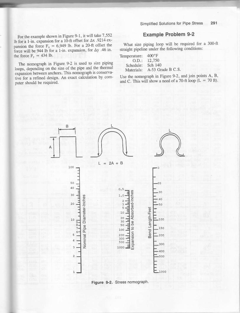
For the example shown in Figure 9-1, it will take 7,552
lb for a l-in. expansion for a 10-ft offset for Ax '9214 ex'
oansion the force F- = 6,949 lb' For a 20-ft offset the
iorce will tr-g44lb for a l-in. expansion. for Ay 46 in'
the force Fv : 434 Ib.
The nomograph in Figure 9-2 is used to size piping
loops, depending on the size of the pipe and the thermal
exoansion between anchors. This nomograph is conserva-
tivi for a refined design' An exact calculation by com-
puter should be required.
B11;f l-t-]JL
L = 2A+B
Simplified Solutions lor Pipe Stress 291
Example Problem 9'2
What size piping loop will be required for a 300-ft
straight pipeline under the following conditions:
TbmDerature: 400"FO.D.: 12,750
Schedule: Sch 140Materials: A-53 Grade B C.S.
Use the nomograph in Figure 9-2, and join points A' B,and C. This will ihow a need of a 70-ft loop (L = 70 ft).
AJ&
1000
100
o-co
Tc)-o:i!x9+<=*o--o 0)^J
oo
o-IJJ
o<)-TooE;-o.9o-(d
'-oz
Flgure 9-2. Stress nomograph'

10Properties of Pipe
The following are the definitions of the tefms used inthe table.
ds : Fifth power ofd, in.5A" = DrlL2: outside pipe surface, ftrlft (ength)Ai : dtr/12 : inside pipe surface, ff/ft Qength)A. : @2 - &)n 14 : metal area, in.2& : d'z rl4 : flow area, in.2W : 3.4A. = weight of pipe, lb/ftW* : 0.433 Ar : weight of water in pipe, lb/ftRg : (UA)', : (V + &1*4 : radius of gyration.
m.I : A.Rl : 0.0491 (Da - 6+; : moment of iner-
tia, in.aZ : 2llD : 0.0982 (D4 - d4yD = section modu-
lus : in.3
Definitions
D = Outside diameter of pipe, in.Sch : Pipe schedule, nondimensionalt : tl6ll thickness, in.d : lnside diameter of pipe. in.
Table 10-1Properties ot Pipe
D Sch T o d" Ao A1 Am Af l.l Ww Rg I z
V8D'.40S
losi40 sT 40s80 xs 80s
.049
.068
.095
.30?
.269
.215.00141.000{6
.105tna
.108
.080
.u50
,1qa
.022
.092
.0?4-u:tr.036
.186
.245
.314
.032
.025 .I215.l l{6
.m09
.0ol I
.mt2
.00{t
.00s2
.0060
Y4D -.540
tosi40 sT {0si80 )<!t 80si
.uoo
.088
.u9
.410
.364
.302
.01159
.00639
.@251 .l4l
.107
.093.09?.t25.I5:I
.132,104$n
.330
.42,5.05?.045
.1694
.1628
.154?
.0028
.qxB
.oqB
.01@
.0123
.0140
3/sD -.675
losl40 sr 4osis{, xs €osi
.uoat
.09t,54!i.i193.423.
.04{xt8
.q2st2
.01354 l1',
.14:l
.129
.tu.124.lDrl
.a
.l9l
. t40
.48
.568
.?39
.r0l
.083
.06t
.2169,2090.l9sl
.0059
.0073
.0086
.01?r
.0216
.02s5
Y2D -.840
l0s40 sT 40s80 xs 80s
160)o(
.oet
.I09
. r87
.2,94
.674
.546
.46{;
.?s2
.13909:09310.04852
nttoq.00102
.ni
.no
-no.ao
.l?8
.163
.l€trt
.uoo
.r97
.2.fi3m.384.504
.J:lrt
.304
.?'34
.l7r
.050
.5-fl
.85t1.088
1.304
,154
.t0l
.074
.t2,
.269
.261
.250
.244
.2t9
.0143n!tt.020I
.02$
.034t
.o.t{n
.0478
.052?
.ofi
292

Properties of Pipe 293
)Table 10-1Continued
e
n.
u-
03 1
t1l.to
I
71i
l) Sch t d d" Ao Ai Am Af Rg I z
3/tD - 1.050
5.:losi
40 sT 40s
80 xsi 8Gs
160
x:<
.154
.t8rl
.na.308
.uqt
.08:l.l t3
.742.or5.614
.434
.g?a
.884
.824
.dtgl
.5398
.3?99
.2249.1401.08?3
.0154
-ztt
t'f1
t11
./tta,
t1l.216
. t94
.16l
.ll3
.201
.252
,,134
.5?0
.664
.6t4
.$lt
.49
.358
.296
.l4s
.683
t let
t.t4t.93?
2.441
-lttl
.va
.064
.288
.81
.349
.3€
.34
.321
.312
.304
.234
.0245ltto',
.0448
.0495
.052?
.05?9
.046'l
.0706
.08!13
.094it
.t0(N
.1I04
ID - 1.315
55l0s
40 sT 4os
80 :c3 8{Et
160
x:E
.l?9
.219
.250
.3$t
.UEO
.lgl
!.16:l1.09?1.049
.95te7,.8I5
.oY5
2^3371.58!)Lno.803.519-Jbu
.0?t
.344
.344
.344
.94
.344,344
.344
.attu
.247
.n5
.N
.230tta
.15?
.639
.?54
.836
1.0?6
.i,4at
.413
.{94
l.lct.94!i.8647tq
.m4
.N,
2.1t22.56{2.844
.86't1.404
.478,409.374atttx,
ttt
.4,(}
.4m
.{o?
.39s
.JOl
.0500
.UIJI
.08?4
.1056lt?t
.t?sz
.l4os
. t606
.1?St1
.lgq!
.2t37
.076{)t't(l
ry4D- l.6A)
55tffi
{o sT 40s
80 xli 8{xit60
xx
-uo!),l$). t{o.19l2g.382
1.530L4A1.380
LnB1.160
3.4092.100
-5t.(
8.384
5.UUit
€!t434434
434€4434
.334
.304
.401
.378
.36t .668
.881l.l0?t.sl4
t.2gtl.ost.630
I.gBl.qB1.498
r.Io81.8052.273t oo?
3.?6s
.648
.458
.273
.s24
.506
.472
.564
.550
.540
.24'€
.3412
.194{t
,1253.1934.2346
-?s14.3421.4lll
rY2D - 1.900
5St
l0s40 sT 40!i
80 xs 80s160
:o(
-uoit.109.145
.200
.?3r
.400
1.s001.33?1.100
t.7701.6821.610
?.594.27t.6l
13.4610.82
497497497
49749?497
-Jaru2.a
.4tr1
.440
.421.olJ.?99
1.068l.$l1.885
2.4512-maqlti| 1etl.404.99)
3.6324.8666.409
L.ZIJt naa
2.7t4
l.uo9.962.882
.@8
.649
.634
.623
.otrt
.581
.549
.t58
.310eol
.{{x}
.568
.loo
.2&
-cuat
2D - 2.3J5
40 sT
55l0s40s
80 xs 80s
t60
xx
.uoal
.109
.154
.16-t
.188
.zta
.3r2
.343
.436
2.2+3
2.6r2.0412.000I O.lO
l-ttr5t.750t.o!:tl.sql
sll'ql46.59.t', 'f.,
35.423?.0027.41
4.17t6.4t13.74
.6n
.6?2
.6U,
.622
.6n
.6?,,
.6n
.6U
.64
.588
.54I
.534
.s24
.508
.491
.458,442
.3gt
.4t2
.rl51.0?4
t.158t.288I.4TI1.6692-0zs2.190
2.856
3.9583.6543.356
3-m3.ra2.9S1
2.7612.{0s?^240
l.Tl4
3.9384.3815.ta
1.6052.6383.6St
5.6'146.884?.44S
9.q'0
I.?t41.582l.4Etl.4l?1.360LnaI |OA
1.041
.loE
.8U
.w2
.?83
./ro
.738
.74
.?qt
.499
.ooo
.?10
.868
1.1021.I63! ,ttt
.42A
.516
.654
.804
.928
.YIY
1.104
2Y2D - 2.8?5
40 sT 4{Xl
8o xs 8trttou
xx
.0gt
.tm
.zxt
.3?5
.552
2.?092.6352.45I)
2,4412382.t2ll.rn
o/.o{3.3
t4s.9
91.8
.t1,
./at
.753
.753
.?a
.709
.690
.6{ti
.608-350
.464
1.039l.?04
1.812z.?s42.945
4.O8
5.lo5.454.79
4.684.24
2.46
7.68210.01
r3.?0
2.4753.5315.?94
2.49€2.361?-o73
2.q26l.&1{t1.536
1.06?
.98{l
.9t5
.9{?
.9€
.92r
.894
.844
.988
l.6t I1.925
2.872
.{95
.ot!tl.oall.l2lr.J!tJl.qt/
1.9s8
3D -3.50O
55t0s
40 sT 40si
.Giil
.t?a
.lzs
.148
.1811
.216
3.3343.2603.250
3.2'0'43,1243.068
41t.9364.2362,6,l,l? a
271.A
,9t6.Ylb
.916
.9i8
.916-tt\t.tt:tl
.&t9
.818
.803
aqtLn4t.325
1.5581.Y502.24
8.r8.35&c)6-t 6/.oo
5.30o-o:t?.58
3.(B4.!l:l4.51
e1a3.61iqo
3.493.323.20
1.208
t.l9{1.186
l.l6f
2.t94t a6t3.018
t.3ml.gnl.8so
.7$t.04t1.080
l.D.tot.724

294 Piping Stress Handbook
Table 10-1Continued
D Sch t d o Ao A1 Am Af |.l Rq I z
(continuod)
3D -3.500
80 xs 80s
160
.241
.254
.406
.€8
.o{.t
3.018t oott ot,
2.900
2-68i
2.6242.300
250244
20s
l4{t
t2464
.9t6
attl.5lo.916
ota
1A.'
.J59
Fily,
2.4622.5S0Z.5IJ
3.0163.1293.950
4.2L35.466
A?I
6.606.49EA'
5.414.ls
8.819.91
10.2s10.64
14.33t8r8
3.103.042.90
2.862.812.46
2.34l.8o
t.lJatl.t5ll.l40
1.0941.047
3.293.{31?q
3.904.014.81
5.040.Ylt
I lar1.962
2.?A42.74a
3.42S
3Y2D -4.000
55tosi
40 sT 40si
80 xs 80s
.083
.tn
. t28
.134
. t48- rtt6
,lta
.344
.469
3.834
3.?44
3.7323.?043.624
3.5483.€83.364
e ala
88taz
69?oa
562480431
269tcl
1.04?1.047
1.0471.04?r.047
1.04?t.04?1.047
t.04?1.04?1.047
1.004.984.980
AT'.970.9,19
.929,900.881
.802
t.0211.4&l
1.628t ?ot2.Al2.680aaa.t.ol6
3.9st5.2C|:}E 7tl
u.0t10.9410.78r0.31
oqoota8.89
9Et.Jo5.84
3.47
a crl
6.09
tz.sl
13.€17.69tt aE
5.004.8t
4.67
4.02.r.6t
3.19
t.372
1.368
1.349
t.3!9
1.298t ,ro1.210
2.78,e,
3.04it.,at4.10
4.79q?tata
o.Db
.9791.3?81.461
r.sa1,6642.050
2.394z.atat3.Ul3.33t4.tn4,925
4D - 4.500
55losi
40 sT 40s
80 xs 80s
t20
t@xx
.083
-ta
.134
.t42
.roE-r )5
.250
.281
alt.r.t,
.500
.574
4.3344.zffi4.244
4.2t6
4.t244.0904.026
4.000
3.900
3.?503-6243.500
3.€83.152
l4d!t371
13581332
119311441058
i024
94?
902
87.O
742
480
1.1781.I781.178
I.t?8I.178l.l?8
l.tIItl.l?8t.178
I t7ql.l?8t. t?8
1.1?8l.l?s1.178
I t7qI t7eI l?a
I l?q1.178
l.lt15
t.1l l1.1081.104
1.080I r1?t
1.054
1.0471.0361.031
t.0211.0151.002
ott.949.916
.900
t t 4tL65lt. tJo
t -4561.9442.247
tqE,11.t l',
3.343.603.74,l oa4.104.41
4.865.59
8. r0
14.?s14.2414.15
14.0?
IJ.JO
tt 7.r
12.s7
t2,t8tt o4
I1.80I1.50
I1.04'tn 1lOA'
9.287.80
3.9t
5.98
7.64
8.66
ta! 7c|
t2.24
13.46t,l oa14.99
16.5219.0021.36
27.54
6.396.1?6.13
6.096.04
5.44
5.1?a tt4.98
4.784.4t
4.O2\t.Jtt
l.coz1.5491.546
1.544t.5421.534
1.5201.510
1.5051.4981.495
1.489l.{8:i1.4?
1.4641.4.t41.425
1.4161.3?4
2.81J.JO4.ZL
4.@
s.9341Cr', t1
8.08q i,t
8.?89.05
10.42
t't t,
t.2{81.2621.869
i.9492.054
2-642.84
o.Jo
3.?0
4.024.27
9.ld
o.,t9
5D:5.563
t0s$ sT 40s
80 xs 80s
t20l@
xx
tno.t34
14,
.438
.500
.?50
5,34S
5.0{7
4.8594.8134.688
4.5634.3134.063
43634t62
270aZJtaI
t492ll0?
1.4551.4s61.456
t.4561.4561.456
1.4561.4561.4s6
1.399l.38rir.321
t.2721.250l.n7l.l9{I l2q1.064
1.882.?S4.30
7.04
7.9S9.70
11.34
u.43a.o220.01
18.5418.1917.26
t4.6112.97
t4-62
?.4.7423.95
27.0432.9?JO-JJ
o tt
8.66
8.037.88
?.06
t.9281.920
1.84?1.8391.819
l.?99
8.€l5.l?
m.58
25.7430.c3:n.64
3.035.45
7 tf,
8.38
10.80

Properties of Pipe 295
Table 10-1Continued
D S ch t dq
d" Ao Ai Am l,J Ww Rq I 7
5
lqs
4{, sT 4osi
80 xs 80si
:o(
.109
.134
.180
.188
.219
.2.&
.€2
.500
.s62
.?18
.864
6.407
6.249
6.071
9.lol5.O25
5.501
4.897
10.8010.389.82
8.2t
?.@
5.04,t 7a2.82
1.7341.734I.734
r.?34
1.7341.734r.?34
t.?34
t.6?71.6641.646
1.640l. qlo1.620
1.6041.589t.588
I qna
t.440t..J.toL?.42
3.$
3.804.41
J.5at
8.40
10.70
15.64
31.?
30.1
29.5
4.92'I.l
24.9
18.8
9.29
12.39
14.99
v.o2
t8.gtl
25.O128.583?,.7!
36.404€t.30ce t?
13.44
13.28
t0 c.a
tl ?,1
lt 2cl
10.76
10.29
8.16
2.3042.295
2.?AO
2.862.2462.248
2.195
2.1042.060
I l€414.40
18.9419.?ln.64
?a.l
€.545.4
49.6
oo.J
4.355.40
6.83
4.428.50
n.al,r tt
14.9811.81
8D-8.625
lnq
20
40 sT 40tt
60
80 xs 80slm
120140
xx
.109
.148
.158
.tTt
.344
.352
.406
.469
.s93
.718
8.407
8.249
q 1q7
8.149
7.93?
', otl7.8757.813
t. oor
7.439
7.001
o.t'lJ
42.O40.lJ5.O
38.2
36.8
35.4
34.232.41t<
al ,
n.821.8to tlo.o
15.4
2.?'58
2.?Sa
2.?58
2.248
2.2€82.258
2.2,58
2,EA
2.A
2.?.8
2.2012,180
2.1602.t52
2.1432.1332.ttI
2.0892.O78
2-0622.045
1.9961.944
t.$r1.8821.833
1.800l.?84
3.944.2A
4.394.9S
1a^8.40
10.48
t2.02
14.95
l5.l I
to oa
21.302t.97
54.554.2
54.053.4
cl a
50.049.5
49.38.747.9
46.445.?$.s
40.6JO.J
9.9113.4014.25
14.9t16.9{18.26
t9.662t.322237
30.43
1t !
40.943.4
53.460.6ot.tt
21.O4
23.44
23.40
22.94
22.45
2I.682t.42
20.8
20. t
18.8
!8.5l7 a
la a
3.00
2.99
2.94,oa
2.922ql
2.89
2.84
35.4
44.4a.z5l.l55.2
63.4
78.482.988.8
100.3105.7lzt.4
140.6
162.0
6.138.2t8.74
9.lot0.29u.05ll aa
12.80r3,39
14.69t6.81
te tota tt20.58
23.2524.522sI4
32.60J!.qt
38.48
10D = 10.750
lGs
() sT 40s
.134
- lEo
tto.250
.u9
.348
10.48210.42010.374
10.34410.31010.250
10.19210.13610.0s4
10,020
tn
118lrtlI l,l
ll0l0?
l0t
2.812.Al2.81
ta!
2.812.81
2.742.73
z.Ez
5.{98.2t
7.24
10.07It 1t
I l.9l
86.3ace84.S
84.0
84.5
80.779.4
?8.9
15.218.?
n.924.7
34.2
3?.4
36.4
34.934.4
\t.lJ
3.7t
J.b93.68
lAt
87.0
100.9l13.?
125.9
I54-0
160.8
ll.?214.3016.t9
l?.4118.78
4.6

296 Piping Stress Handbook
Table 10-1Continued
n Sch ? o Ao A'I Am Af t,J tlJw Rg I 7
(continurd)
toD - 10.750
60 xs 80s
80l0o
lb140
..JYC
.5@
.sll
.59:t
.?18
.?50
.8,([email protected]@
t.t2s
9.9609.?!t09.68?
9.5649.3149.250
9.064q ?q/t
8.625
8,500
98.088.185.3
80.0
ol.l
61.29I.J
44.4
2.81z.At2.Al
2.81,912.81
z,8l2.812.8t
2.81
L6r?.552.54
2.502.42.42
2.372.42-26
?-a
12.8516.t0l?.06
18.924'823.56
6.U30.6332.3!t
3,l.Oa
?t.9
?3.?
tt.a68.1tt.264.s60.l58.4
56.?
(3.?54.?58.0
64.3
80. t89.2
l0{.1109.9
lt5.?
32.33t.9
3l.t29.529.1
n.9.0
25.3
24.6
3.663.633.62
3.60J.503.stt
3.523.4?3.4It
3.{il
172-52t2.0u.4244.9?€.8.2296.3
*4.336-t.9384.0
399.4
3?- I3!'.441.5
{t.5sit255.1
@.368.4?I.4
?4.3
t2D-12-7fi
ST
xst 80s
n
30
44
60
8{tt00
INl.o
160
55t0s
40st
.156
.td)
.203
.2t9
.N
.?.fi
.n93{n.!80
.344
.t' ID
.406
.418
.500
.s62
.@5
.EIOI
.8{3
.crs1.0o0I.IZJ
1.2t9t.3t2
12.{nt12.390t?^344
12.312p.n4t2.Nt2.t92r2.15012.090
t2.06212.000I t.938
I1.844I l.?50I1.648
I t.500I t.s16I1.064
ll.@010.?5010.s00
I0.313t0.126
29882u72A32;19
u6269zo:t258
it5!l249242
88n42t2
mll9tloo
l6ll{4r8u?106
3.343.343.34
3.343.343.34
3.3{3.343.34
3.343.343.34
3.343,343.34
3.343.343.34
3.343.343.34
3.343.34
3.253.243.el
3-n3.2t3.Zl
3.193.t83.I?
3.163.143.13
3.I I3.083.04
3.012.982.90
2.8{l2.812J5
2.20taa
6.17?.ll8.(x!
8.629.369.82
I0.93ll.nl12.88
13.4tt4.5815.?4
16.9419.2{2L.52
23.8t?.6.&31.5!l
32.6436.914l.ott
44.t447.14
12t,5120.61t9.7
ITY.I118.3It?.9
I t6.?ll0.Yn4.8
I14.3u3.lttl o
ll0.?108.4106.2
103.9101.696.1
95.090.8oo.o
eet80.5
2t.o24.227.2
29.331.83it.4
s7.239.943.8
4It.649.653.5
5t.665.473.2
80.988.5
10t.2
ul.0t2s.5r39.?
t5o.tt60.3
52.6s2.25r.8
51.65t.251.0
s0.650.2-19.?
4S).5
49.048.5
47.94?.046.0
45.044.041.6
4l.t39.3.tt.o
36.234.9
4.454,444.44
4.{34.44.42
4.4t4.404.3!)
4.394.384.3?
4.364.3it{.31
4.84.2t4.24.2t4.174.13
4.104.0?
1?9'4140.515t.5
212.7ut.s248.5
258n9300
3At3$2401
€94?5562
sl9642?01
242?81
t9.2a.oz4.l26.628.7qr.lgt.435.?39.0
40.5{3.847.1
50.456.?62.8
68.8?4.588.1
90.8tm.?lno o
116.4tn.8
l4D - 14.000
l0n30 ST
40
xst60
.188
.ui
.25
.250
.312
.3?S
.406
.43{t
.4dt
.500to2
.525
13.624t3.560t3.524
13.5{n13.3?513.2s0
13.188l3.l2sr3.062
469459452
4484A408
aI60
389380
3?13453:l?
3.62J.0laFl
3.6"f3.6?4A:,
3.6?3.673.67
3.6?3.6?3.67
t Et
3.5s3.54
3.533.503.47
3.453.{43.42
3.40i"<3.34
8.169.s2
10,29
10.80t3.44IO.UJ
17.34t8.6619.94
2t-zt24.9A26.26
l4It.8144.4143.6
l4il.1l4(,.st3?.9
136.6
134.0
132.?t29.0tn.7
tz.7g2-4
35.0
JO..a
4tt.?54.6
59.063.467.8
72.184.989.3
qt. r6'2.562,2
62.060.8EOt
59.158.658.0
JI.Jc5-6
55.3
4.8{t4.gI4-gI
4.864.844.82
4.814.804.79
4.784.744.?3
19526242S5
otJ3nl
40t484S7
484562589
27.A32.334.8
36.s45.05:t.3
5t.361.465.3
69.180.384.1

Properties of Pipe 297
Table 10-1Continued
I
IiI
I
D Sch t dq
o Ao Al Am hI Rq I z
(contiaucd)
l4D- 14.000
80I00
120140
160
.ooo
.?50
1.0931.2501.344
1.406
12.68812.500t2.r?s
u.814I1.500
I1.188
262
Itc
.r rf
.t.ot
a .tt
., 1.'
a^o3.0r2.96
2.93
38.4?
4d32s0.0?$.44
cat.*t
126.412,,.7lr5-5
98.3
93.5t06.1t30.8
150.7
181.6
189.1
54.8c.t I
50.0
47.54{i.0€,542-6
4.694.63
4.584.534.50
{.48
614oit/atz5
930lo271082
8t.798.2
117.9
t32.8t46.8154.6
t59.6
l6D- 16.0@
!0
30 ST
4() xsi
80l@tmI40
t60
,I88.28.2fi.Bl.312.3,14
.406
.€8
.469
.500E.t i
.750
.8€t.$rt.218
t.4il8l.5ml.sg!
t5.624I5.52415.500
15.438
la ttl5.loo15.124
15.06215.00014.938
14.68814.625t4.500
14.3r413.938t3.56{
t3.12413.000t2.at4
ott902895
842
808
744
684boc64t
601
459
38!)rtll345
4.194. t94.t9
4.194.194.19
4.194.194.19
4.194.194.19
4.I94.194.19
4.I94.194.19
4. t94.194.19
4.094.064.06
4.044.024.01
3.98
3.94toe,l ot
2qq
3.80,t ?4
3.443.40
9.34I t.?s
ts.40I6.92
18.41lq qo
2t.4I
4.824.35
31.62
35.S0
40.1448.48co.00
oat..l'
tot tr89.3too. tt*r,
184.1
t82-7l8l -2
l1e a114 'lt?5.3
t69.4t 68.0
160.9t52.6144.5
135.3
129.0
31.840.142.1
47.252.{ct.5
72.8
lt.o82.4x, 'l
IUI.J1t2.4
lJo.c16,{.8
23,2.324{t.l
a2n82.0ol-r
8l.l80.41d'l
?9.178.4tt.6
7r.2
?3.472.7
66. t62.6
4.5(|5.5:l5.5{
J.$t5.525.50
5.{95.485.4?
5.$s.42s.40
5.295.23
ttt9.lt5.t2
JOO
384
474qto
ou5549
',.,',
t047
I157lJoat1550
l?5t18151894
.to"545.848.0
53.659.364.8
8l.I
91.5
llo.D12t.4
144.6I?0.5194.5
?.m.1
236.7
t8D- 18.00O
l0?n
40
ST
xs
60
80
100120t40
tou
.2W
.€8
.5@
.562
.594
.719
.?50
.812
1.688t.?8t
l?.500It itqt7.?.fi
t?.00016.876
t6.81316.75016.562
16.500
t5.06615.250I {.876
14.625t4.438
l64l1584
t472t4201369
1344IJI''1247
1?23
t090
950
azl
4.714.?l
4.?l
4.?l
4.5{t4.554.52
4.484.4Ii4.42
4.aa4.394.34
4,32,i.294.n4.lr3,993.89
3.&t3.?8
13.9417.36
u.t7n.4930.?9
32.4634.t238.98
40.6l43.8?
I t,l'r80.65
86.{890.?3
240.5
tn, ,
w.3ut-o
n2.0m.42!5.5
213.82t0.6m4.2
193.3142.7
Itt6-utdt.?
59.070.6
82.2oac
l0{.?
110.4u6.0132,5
138.2149.2lm.8208.O244.2?74.3
294.0308.5
104.11t2.7t01.2
99.?98.396.9
9!i.4
92.691.28r'.4
83.?70 1
6.286.2ts
atr6.I96.tz
o-r56.12
6.106.086.0{
s.gt5.905.84
5.80
549
luc\tt 17t
L1J L
t2891458
l5l51624IE}4
218024982750
29083020
61.0
103.6lt?.0130.2
136.8143.3t6a0
168,3180.52G3.8
?|22,8I-A$!!.5
323.1als.6

298 Piping Stress Handbook
Table 10-1Continued
D Sch t ) o Ao Ai Am Af lt !'Jw R9 I z
20D - 20.000
t0
20 sT
30 xs
40
6{'
80
r00t6140
l60
.250
.3t2
.sls
.4its
.5tI,
.552
.593
.62s
.8tz
.EIO
1.03t
1.2s01.28t1.500
l.?501.8441.968
[email protected]?5r9.250
t9.12419.000!e a?t
18.814I8.?5018.376
18.25018. tSItl?.938l?.5@17.€817.000
16.500lo.Jl!t16.0€4
2.822.732.64
2.562.482.N2.36
2.to2.021.99r.861.64l.6t1.42
t.ut.t61.07
5.245.243.24
5.245.245.24
3.45.245.24
5.245.245.24
5.245.245.Zt5.245.245.?A
5.115.0?5.04(nt4.9?4.94
4.934.914.8t4.?84.?64.70
4.584.'r4.4{t
4.94.n4.21
!9.36ta t,26.930.634.336.238.048.9
52.€54,361.4J!t.o?5.387.2
I00.3t0s.2I rl.5
298.6294.8291.0
?at.z283.5t29.8n8.0t?a I?,43.2
261.6259.8252.7
244.5238.8n.02t3.8209.02,02.7
52.7o.t.6?8.6
91.5t04.IIt6.8tu.g129.3t65.4l''a aI84.8208.9
250.3256.12,€8,4
341.1Jilt.53?9.I
12s.3LZt.O126.0
124.4tu.8
120.4ltoall{.8ttt
"IIZ.J109.4
104.1lct.498.3
92.890.5atl.at
6.986.966.94
6.926.906.88
6.88
o.l96.71o.lo6.726.646.63
6.485.4tt6.4I
tat938
ll141289l4{i71624
t?04t787ucl2&92483tTn32s!&[6aa9.|
42174379{586
?qt35.tt
lu.4128.9l4{i.?l5a4t?0.4l?8.78.7240.924a.3ztt.2325.1Ett.6it!9.542t.7{3:1.94S8.8
22D-2Co0
l0 st:<!t
.?g
.500
2t.s@2t.?so21.0m
4.594.3it4.08
o.to
c.,t0
5.dlt.oo
l?.r25.533.8
363
34ti
58.1do.b
114.8153.6l5{r.0
?.69l -Dil?.@
t0l01490I OCtl
9t.8l3!i.4171t.5
24D:2{,000
l0
20 sT
xs30
40
@
80
t0otm140
160
.?.&
.312
.irri'
.€8
.o{r,
.DOZ
.625
.6Al
.750
.968l.oallt.2r8t.531I.8122.0t22.188?-3+3
23.50023.3764.?,fia.ps23.00022.876
4.7504.626n.w22.06421.93821.564
20.93820.376r9.8?6
19.52sr9.3t4
7.r7o.Yat6.?9
6.44
6.095.93o.l r5.235.084.66
4.023.5r3.102.912.69
6.86.288.246.2A8.?A8.2A
6.286.46.46.286.46.24
6.286.286.23
6.286.8
o-15alt6.09
6.025.99
5.925.895.785.74J.O:l
5.48C.JJ5.20s.t49-UO
18.?8.227.8
32.436.941.4
{ti.950.354.870.0
a7.2
t08.1126.3t42.1
149.9159.4
4344N4?S
42'o4154ll{06442398
3A3?8!50:|
344326310
302293
63.4?8.994.6
ll0.t129.5140.7
156.0l7l I186.3
238.1?l,2.9296.4
36"?.4429.4483.2
509.?542.0
l8?.8185.8l&!.8181.9l TCt q
l?8.0i76.0
t72.2loat.olo.t.l106.t
t49.1t4t.z134.3
t31.0
8.4{)at.Jatd.,t:l
o.$t8.318.29
8.27
a.?.2
8.ls8.ts8.07
7.gI?.?9J. tc7.70
t3t6toiatl9{l22492550?a40
31403420or lu46S34920
68527&48630
90109455
r09.6135.8161.9
lgr.4212.5237.O
28S309
3884t04?3
5n65:l?t9?5trtttt
26D - 26.000
saxl;
.JI5
.5008.zfi25.0q)
10.26 o-615.81
o-ot6.54
30.2 50149t
102.5136.2
216.8tlt E
9.069.02
2479 t9l250
30D-30.000
t0ST
20 xll30
,312
.438
.500
29.3?6
2.9.t25
29.000tQ a.ra8.zfi
21.92t.421.020.520. t!o a
l -64,?.85
?.8!r
7.69l.Eto'1.62
7.597qa7.53
34.940.6
46.352.0
at86?2ooo
661qtit649
98.9lt8.?138.0
t5l-ol?6.8195.1
293.5291.0?.88.4
286_0
28t,1
t0.5010.48l0.4It10.4r10.4110.3!t
3210,lta.,4€450il{l
6230
2t4
336
4ls
34D - 34.00O
STxs
-J/5.s00
3:t.zso33.000
40.539. t
a aal
8.908.?08.64
39.65Z-O
868 134.7178.9
3?6.0370.3
11.89I l.ato
oo95 1to{34
36D - 36.0@
STxs
.r.rE
.5m35.2s03:i.000
54.452.5
9.449.44
42.Oc5-o
Ylo962
142-7189.6
4U.6{16.6
12.6012.55
ob5Y61t'0 488
42D - 42.000
STxli
II'E
.50041.25041.000
119.4115.9
I t.0I1.0
10.8010.13
49.0 IJ.to1320
I66.??€1.6
5?8.?57t.7
t4.7214.67
1052tt4{xt?
50€668

L1
Weight of PiPe and ComPonents
When determining the weight of the pipe qnd compo-
nents, several factois must be taken into consideration:
o Weipht of pipe : lJse the values for properties for carbon
steej pipe as a standard. These values can be found in
Chapiei tO. The relative weight factors for other mate-
rials are:
Aluminum = 0'35Brass : l.l2Cast ircn : 0'91Copper = l,l4Fefrtic stainless steel : 0'95Austenitic stainless steel = 1.@
Weight and Dimensions o{Pipe and ComPonents
c lhbight of iwulntion of the PiPe
I = Insulation density, 1b/ft3
T : Irsulation thiclness, in.D = Outside diameter of PiPe' in.
Weight of insulation : .0218 IT (D+f; = 67n
Values for insulati.on densitY:
ll lb/ft310 to 11 1b/ft311.53 lb/ft3r9-2rlbltr2rrbltr?AIbItr?5tbltr2.3rbltr16 lb/ft39 rb/ff91b/ft38lb/ff
Tables 11-1 Orough 11-10 give the weiglt of insulation
and various pipe componens by size.
The following pages are tables and figures showing
standard dimensions of flanges, fittings' valves, anct ptpe
bends.
{arbon !Wrbught 0.98
, ,r)
Calcium silicate85% magnesiumThermobestosKAIJODiatomaceous earth =High temperatureSuper-XFoly-UrethaneAmosite asbestos
FoamglasCellular glass
Mineral woolDepleted uanium
t Wigtrt of water in pipe: See the proper.ties of pipe inChapter 10.
299

Piping Stress Handbook
Table 11-lWeight of Insulation
(lb/linear ft)PlpeSlze Thickness of Insulation
21h" 3112"I1.52346810t2t416l82024262830J2
3642
.72
.841.011.25t.622.tl
1.35| .712.082.5s3.284.135.206.046.r66.90
8.4510.010.411.2I 1.912.713.4t4.216.5
1.942.522.533.01J.Ol4.5'75.647 .078. l38.389.33
10.411.6t3.414.115. I16.1t7 .l18.219.222.2
2.',|63.473.484.O',l
4.666.097.8s8.93
10.510.712.013.314.6r7 .018.019.220.521.723.0
28.0
3.704.524.425.246.077 .609.48
11.012.713. l14.616.3l7 .721.02r.923.425.026.528.O29.s34.0
5.596.657 .489.82
11.5t3.215. I15.8t7 .519.321.124.826.027 .829.531.3JJ. I
34.840.1
9.1011.513.815.51'7 .418.520.522.624.628.730.232.2JZ+. J36.338.340.346.4
16.018. I20.42t.323.625.928.132.934.636.939.r41.143.'745.952.2
41.644.146.649.151.759.2
51.454.457 .560.5bJ-)72.6
* me tublc is based on calcium silicate at I t tb/ff and nust be adjutt"d 1o, olnt ^ot"riol".
rn" tort" iiuaiionaig *d-o*rin. ."ighr.
Table 11-2Weight of Flanged Gate Valves
(tb)
Table 11-3weight ot wetd End cate valves
(tb)Rating600# 900#
Size(inJ 150# 300# 400# 1500# 2500# 150# 300# 400#
Ratlng600# 900#
Size(in.)
I1.523
468
t0t2t416l82024
JI
455595
140240/100
630830
1,1501,5801,9102,3503,900
136256460610
1,4102,600
3568 9l75 115t4s 194215 270420 530700 940
1,050 1,5301,490 2,0w2,170 2,4102,800 3,5003,7204,907 ,380
314330 430720 900
1,220 |,5601,880 2,3502,630 35W3,2W 4,6804,230 6,5007,2W9,800
I 1,800
I1.5 292453804 1206 2108 340
l0 55012 73014 99016 1,46018 |,73020 2,20024 3,350
205560
120170 220360 460590 8309r0 r,250
1,220 1,800|,960 2,2102,550 3,10033N 3,76s4,3506,700
257080
155 260270 350&0 750
1,080 1,3001,610 1,9702,240 3,2N3,000 4,3504,030 6,0006,7608,950
10,500
80125190410520
1,2501,910
CourEsy of Crane Co. Courtesy of Crane Co.

Table 11-4Welgtrt of Flanged Check (Swing) valves
(tb)
. Weight and Dimensions of Pipe and Gomponents 301
Table I l'5weight of wdd End Check (Swing) l/alves
(lb)
Size Ratlng(ln.) 150# 3OO# 4OO# 600# 900# 1500# 2500#
Size400#
Ratlng600#
234623 65 120
70 160140 180 280
47 5580 100 155
130 190 210 240zffi 310 420 500510 580 740 890760 820 880
1,015 1,150 r,200
900# 1500# 2500#
130zto390780
1,320
4 100 180 2W 260 340 630
6 2N 330 395 530 640 1,360
8 390 620 680 900 1,180 2'100l0 510 9m 9N 1,440 2'170t2 775 r,2n 1,250 |,970t4 1,200 1,65016 1,450 2,05018 2,42020a^
.t 1<
3504 1006 1608 360
10t2t4t6182024
Courtesy of Ctaw Co. Counesy of Crane Co.
Table 1 1-6vrteight of Flanged Globe \hlves
(lb)
Table 11'7tlreight of weld End Globe \ralves
(tb)
Slze Ratlng150# 300# 400# 600#
115191318782
1,2:U.
slze Ratlng(in.) 150# 3OO# 4OO# 600# 900# 1500# 2500#
2347578973 75 115 130 L6 170 185
+ 120 179 206 272 2N 285
6 220 332 401 656 630 680
8 363 530 900 1,100 1'1'+0 l'370
900# 1500# 2500#
2t5 21546 4fi490 65920 1,890
79 90139 160214 233396 476a8 820686
2J468
l0t21416182024
80t40250a0598824
1,0561,160
r,730 2,4002,7N 3,0243,850 4,lm0
10 53512 794L4l6182024
Councst oI craie co. Courtesy of Cratv C'a.
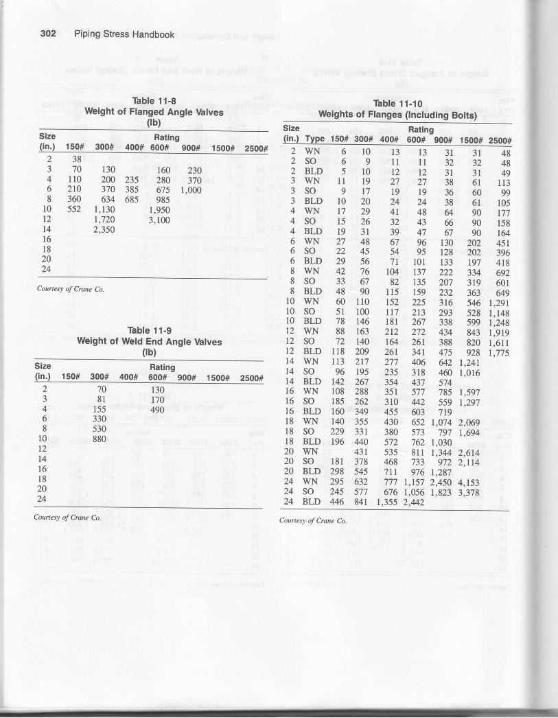
Piping Stress Handbook
Table 11-BWbight of Flanged Angle \hlves
0b)Ratng
150# 300# 400# 600# 900#
130 160 2302N 235 280 370370 385 675 1,000634 685 985
1,130 1,950r,720 3,1002,350
Counes! of Crune Co.
Table 11-9Weight of Weld End Angte Valves
(tb)
Ratingr50# 300# 400# 600# 900# 15oo# 2soo#
Table 11-10Wbights ot Flanges (tnctuding Botts)
2384 1106 zl08 36010 55212
14lo1820
2WN 6 10 13 13 31 31 482SO 6 9 11 tl 32 32 482 BLD 5 10 12 12 31 31 493 WN 11 19 27 27 38 61 1133SO 9 17 19 19 36 60 gg3 BLD 10 20 24 24 38 61 1054WN t7 29 4t 48 g 90 r774SO 15 26 32 43 6 90 1584 BLD 19 31 39 47 67 90 1646 WN 27 48 67 96 130 202 4516 SO 22 45 54 95 r28 2U 3966 BLD 29 56 71 101 133 197 4188 WN 42 76 104 137 222 334 6928 SO 33 67 82 135 207 3t9 60i8 BLD 48 90 115 159 232 363 gg
l0 wN 60 110 152 225 316 546 1,29110 so 51 100 117 213 293 528 1.148r0 BLD 78 146 t8l 267 338 5gg t.245f2 wN 88 163 212 272 434 843 1.91912 SO 72 140 1& 261 388 820 1,611t2 BLD 118 209 26t 341 475 928 1,77514 WN 11,3 217 277 406 642 1,24114 SO 96 195 235 318 4@ 1,01614 BLD r42 267 354 437 s7416 WN 108 288 351 577 785 1,59716 SO t85 262 310 42 559 1,29716 BLD 160 349 455 @3 71918 wN 140 355 430 652 1.074 2.069l8 so 229 33t 380 s73 797 t,69418 BLD 196 440 572 762 1,03020 wN 43r 535 8lt 1.344 2.61420 so 181 378 468 733 972 2,11420 BLD 298 545 7tt 976 r,28724 WN 295 632 777 1,157 2,450 4,15324 SO 245 577 676 1,056 1,823 3,37824 BLD 446 Ur 1.355 2.442
(inJ
r30r70490
708l
155330530880
234o8
10t2t416182024
Courtesy ol Crane Co. Courte\) of Crane Co.

Weight and Dimensions of Pipe and Components 303
r-l-TI t*ll tl_n Llt-M+l
Stub End
F-c.---
a/r- 1t( '(-1 L__-r-'9Oo Lonr Rodl'rr
Iong Tang.6ton on. lnd
5l..l9hl Cror!
/--*\-T/ ,--\ \Jtg":J-tl*G--!Shorl RodlurR.turn a.nd
/ ,,--\ \ k/ini\ll+, \#ll.-H- +llong RodlurR.lurn B.nd
F--A---l,."nf-/..'- n
tiiJ9oo t!ng t.dlu.
llbowStroighl or
MR.lnfor.lns
w.ldlnr 5!ddl.
Steel Butt-Welding Fittings (in.)Courtesy of Crane Co.
S.cndad, Exrrc st'ots. S.rrcduL 160,ad Doubl. Exrro Strcns FitrinE.trov. tr|. ro,n. outdd. din.ttiott.
Arnerican Standard: These fittingsconform, in sizes and types includedtherein, to lhe American Standard,B r 6.q- r qi8; see page 2gr.
Thickness: Stendard Fittings r z-inchand smaller ate made for use withStandard pipe (heaviest weight on 8,ro, and r zjinch sizes);sizes r4-inch andlarger are made for use with O.D. pipefu-inch thick,Exrra Strong Fittings rz-inch andsmaller are made for use wilh ExlraStrong pipe; larger sizes are made foruse with O.D. pipe \/2-inch Lhick.
Schedule r60 Fittings are r''"'le for usewith Schedule r6o pipe.
Double Extra Strong Fittjngs are madefor use with Double Extra Slrong pipe
T-/:t ilt i lllill" --r-'llfT U- b .--ul
l._E-*EiR.du.lns T.. R.ducinr Crott
Dincnrion "T" it rhown in tobl. beloe;r.f.r lo lors. loblc for diln€nrion "E".
aA .NT/f 4 -A/ >LJJ
"1.-J9Oo Shorr Rodlu. 45o lons Rodlut:tbov, Elbow
e]c"P
mlurl9oo Typ.
[_-\tll!--/-lk- s ---r
Shap!d Nlppl.!
[\tL____J)k- s -_-'l
1 | | tlF\ i /i-t-:-L I
20xlE'
ExtrStrorSize B D F H J M N P a S
Yzs/t
Ilr,
rYLr'/e1Yz17/g
Ilr/t
6/s
7/ra
'/eI
lr/a'1rh,r1h.
lr/ztrk
22r/z
2Y13
33/tlVs
2r/ta
lr6/tslr YraL-/r62?/t
lrr/re2
2r/z4 I
lr/*.4r/s43/t
2444t)404n
80808080
lYz
2Vz 33/t4r/z
lr/z
t'/2
3r/r4r/r
5ta
ttatt/sl3/tx
2ra,zYz
3Ve
trh1rh1r/z2
34
6
4th
7r/z9
L'/163tAs
31 6/re
4a/t
J'/14t/rs53/ro6Yt
27/s
33/ttYE
4566
rYEIYElYglr/a
1Yt51 6/re
67/rat -/16
zYz3
3r/z3r/z
4040404
80808080
3r/z t'/a6
t'/z9
31h
6
6t/tt'/29
l0s/a
2r/.2Yz3Yt3.4
33/t4Y847/E
5'/t
zrhzrh 8
10rt 18
6r/t73/t95/te
\r/al0t/ta12r/ e
5Vz63/rsI -/L681/z
6
8t
lr/ttsht?/s1r/z
8r/rs8e/ro93/s
113/t
40404040
80808080
E
l0t2
151t2l
8l0t2
133/tt7
20rh6Ut '/28./t
8r/210ll.
t
66r/z
16
2428
30
l2E/rs153/e
18%
165/rezoYs248h
28
10n/s
tx|/al5
t6ta
81010
22rh23/t3r/t
t43/at77/s201/.22YB
67813
4040
l0
80i16t820
24
3036
182024
l0llr/t12r/2
12.t3rh.15'
769
toth404E
48s460 30
364048
tath
x317r/t
3r/z 24r/626yE30r/a34r/E
L4
2020
JO
2020
40
t0

304 Piping Stress Handbook
150 ond 3oO-Pound
Scr6v.d Flon9.400, 600, 9O0, 1500, ond 2500-Pou.e
Cron.lop Fl.nso4OO, 600, 900, | 500, o.d 250o-Poqnd
W!ldlng N.Gk Flans.150 ond 3O0-Pound
W.ldins No<k Flanrc40O, 600, 9O0, 1500, ond 2soo-Pound
Forged Steel Flanges (in.)Courtesy of Crane Co.
Slip-On W6lding Flqn!.150 ond 30O-Pound
5lip-On !Y.ldi.s Fldns!400. 600, 9O0, ond l5o0-Pound
Class PipeSiie D Bolts
E H
150Pound
lr/t
Vz3/t
I
3Vz31/8
4Y.45/^
1/ts
Yze/rs3A
l3/slrr/ra
22y2
2YE
13/t3Yg3t/c 4
r/-
Y2
Yzr/
'/a
tL/-^|3/.-
l7/e2r/ra23/re
0.841.051.321.66
'/e
"/arr/retxt -
1r/z22W
67
7r/t
I Vre3A
%rtl"
2TB
35/e
4Yg5
37/8
4r/.5lz6
^/2
-/a5/s
%I
lygl3Aa
21/re2Y2Tta23/t
1.902.382.883.50
%1
lY813/,,
3Y2 8Vz9l0T1
I B/ts
r,/rsI
5r/z6sAs/ -/16ar/z
77Yz8r/z9Vt
8E
E
8
5/z
5/e
x/t
rY1t-/lB17/rs
2r3/rs3
3Y23r/z
4.004.50
6.63
rut -/16
lTActe/,"
E
1017,
l4
l3Y2l61921
lyEl3/rslr/r13/,
los/a123/t
t6rL
ll3/tl4Ytt7
18./t
E '/1f6%I
t3/t1rs/rexl/rs2r/r,
4Y2
8.63to-75
14.00
l3/tlr5/rt2t/re3Y"
l6182024
x3r/z
27Yz
l7/rele/ralrr/ra11h
l8Y22T
27r/^
2lY4223/t
xqr/,
l6l62020
1
lYalYelr/t
2Y22rYre
27/8
3U,
5r/25rr/te
6
16.00r E.0020.0024.O0
37/relr3/rt4r/ra
300Pound
u'rrIlrh
33/e
45/e
4YB'/a
rr/ra
l3/elrr/ra
22,r/t
Ls/e
3r/t3W37/e 4
Y25/s
'/a
7/s
1
lr/rsrllc
2r/ra2r/e
27Aa
0.841.05
r.66
IlrAa
lr/z22U3
6YA
6th7V28Ut
t3/--
%I
lYs
27/8
3./a4Y8
4rh
s%6./e
E
88
3/ts/e
3/t
l3/ra )
ts/rel
,i\i,"l
2rt/ta
33Ve
1.902.382.883.50
l3Asl5/rslY2
lrr/r,3Y24
6
9l0l1
t2r/,
l3/rslr/tl3/st4c
5Y263/ts75Ae8r/z
7V7TE9Y1105/n
E
88t2
"/a'/1'/l3/"
r3alTg
22rAa
33/rs33/s
37/g
37/a
4.004.50
6.63
Lfa
8l0t2t4
17Y2
20Yz
l5/al7/a2
2Vt
lo3/e12t/t
16r/,
1sY1t7t/t20r/a
16
20
TEI
lr/slVa
27/tex'/s27h
3
43/s
45/e
5Y855/e
8.6310.7512.7514.00
77As33/t4
l6l820
25W2E
30rh36
xY123/e
2Yz23/r,
lEYz21
27tA
22W24t/e
27
20x42424
lY.lr/elYalr/"
3Y43W33/t
53/t6r/t6t/a6./a
r6.001E.0020.0024.00
4t/rt'/a5V26
400Pound
5l0ll
12r/z
l3/etr/z1s/*
6sAst -/168!z
77/a
9rato6/^
8E
t2
%%7h
2z\g2r/t
3Y2
4t/,"
4.50
6.63
2zrh2V,
E
l0l,l4
17r/zloYz
l1/B
xYE
2Yt2s/p.
lo'/al2t/e
r6Yt
l5Y1t73/a20r/t
t2
l620
IIYBlY4lr/t
2rrAe27/B
3YB
3sle
47/B
53/e
57/a
E.63r0.7512.7514.00
rr/rs4
4V.
1618x0
25Yz2a
3or/z36
2r/z25/c
2r/t3
tgt/z21
77r/^
21Yz2434
27
20
2424
l3/st./Elr/zt3a
3rr/rs31h
4r/,
66Y26E/a
67/*
16.0018.0020.0024.00
53/s
5t/t
C.oh.l.p Flong.150 ond 3oo-Pound

Weight and Dimensions of Pipe and Components 305
Forged Steel Flanges (in.) Continued.Courtesy of Crane Co.
ClassPipeSize B c D
Bolts G HDia.
600Pound
lz-/1
IrY1
3x/e
41/s
47h5r/t
116'/a
rt/tsr3/,"
l3/elr Yre
22r/2
t./a3r/t3r/z31h.
Y2
'/e'/a
7h
I1r/rsrYa
2Yraxr/t
21/raL5/e
0.841.05
1.66
I/s
1
lr/ratv"
lYz2z\z3
6Yg6Y27r/z81/^
7/e
IIYBlYt
x7/8
4YE
4Y25
6s/e,
888
'/L-/Bt/t3A
l|/t11/tal5/e
lr3/rc
23/t27h3Y83r/^
1.907.382.883.50
rvlTAals/e
lr3/r'
6
lo3/t13l4
lr/zl3/elr/p.
63/rat -/16gYz
8r/zloYzrrv
88
11
1/B
II
2r/B
1,5/^
Lr/^
45/e
4.50--)6.63
zY8L"/e
E
10t2l4
l6t/z20
233/L
2r/,2r/eX3/t
lo5/s123/a
16r/a
t33At7
19Y1X03/a
t2l620z0
lYglr/tlY4l3/t
J33/s
3rr/ts
5Y16
6Yg6Vz
8.6310.75
14.00
343/a
4s/s
182024
2729Yt
33r/a3Yz
l8Y2
27r/t
233/e
2.53/t
28r/z
2020
lr/zl5/eL'/Al7/a
43Ae46/a
$t/z
77\/a7Yz
E
16.0018.0020.0024.00
5r/z6
6Yz
900Pound
3 9YzllY2133/t
15
lY2t3/t2
23Ae
563/ra75/ra8rh
t '/29r/tll
11,y,
888t2
7/B
lYalrarVa
2Y82e/t3Yg33/e
4Yz
5r/z
3.504.50
6.63
2Ys23/e
3Y6
E
l0
t4
t8t/z2lYz
2425r/^
2Y273/t3YB
33/t
1o7slx"/o
t6rh
l5t/2l8Y2
22
12l62020
l3/el3/el3/e11/z
4V4V8
63/e
7Yt77/a
83/a
8.6310.7512.7 514.00
4Yz
5s/s6Va
l6182024
X73/t
133/t4l
3r/z
4Ya5r/z
lSYz
27Vt
2Ar/qx7
29U35r/z
202020xo
r'/al7/s2
ZYz
t'/a6
6VE
81/z
993/tllr/z
r6.0018.0020.0024.00
6Y2/ '/28r/tt0v
1500Pound
r/z
'/1IlY1
4t/t9r/e57/g
6r/r,
%I
lr/srVR
l3/slrr/rs
22r/z
3Y43Y2
43/z 4
"/a-/A7/E
1/"
lY1l3/elt/eF/a
23/e
23/a
27/B
27/e
0.841.05
1.66
lYllx/sl5/a
lYz22W3
78r/z96/e
t0rh
lr/nlYzl5/sl7/e
x7/e
35/e
4YB
47/s
6r/,7r/z
E
E
d
E
I%I
rYa
lr/a2V21/z
27h.
3V
4Y84s/a
1.902.382.883.50
13/t2YtIYz
6
lxr/t143/tt5y,
zYB
27/B
3r/^
63AaTsAs8r/,
9Y2llYz12r/2
8E
tz
rvlr/zl3/a
3e/ts4Y8
4rr/ts
47/e
6Ys63/t
4.50
6.63
3e/re4YB
4rrA,8
l0txl4
19
26Yz29r/2
35/a
4r/t47h5r/t
t05/B123/t
l6r/t
rsYzl9
22\/2 16l6
l6/tl7/82
'),r/^
5'/a6V
83/s
10lrYBtt3/a
8.63t0.75t2.7514.00
55/a
78%9r/"
2500Pound
Yzt/a
Ilr,
5Y4sw6V7r/
lB/raIta13/e
lV2
l3/elrr/te
22r/z
3Y233/t4r/a5Va
ta3/a
%I
r'/t6lLYra1I/s
2rAa
27/8
3Ys3r/z3t/^
0.841.05t.321.66
lsAe1r%otlA
2rAa
lYz22Y23
8evlor/ztt
ls/t2
zYl
27/s
33/e
4r/s
53463/t734
9
4E
8E
lYsI
IYBlVt
23/s
23/e
3Y835/e
43/e
5'/e6r/e
1.902.3E2.88
2./t3Y8
56
t4l6Yzl9
335/e
41A
63/rat -/t58Yz
lo3/t123/tl4r/,
8tE
lVz
2
4V5VE
6
7Yz9
tosa
4.50
6.63
4Yl5th
810t2
2lt/t26y.
30
56rh7Yt
lo5/s123/tt5
17 r/t2trh243/e
t2 22r/z2.4
9t0
l1Y2l6Yzl8r/t
8.631o.7512.75
9l0

Piping Stress Handbook
Cast Steel Wedge Gate Valves150- to 1500-Pound Dimensions
Courtesy of Crane Co.
E-TFEh I
ltf IJIK D
Ylf i*/- i\ I
-=] IT--T--T I
fi=-l='il1r-i--ll-c----lBun-W.lding
E-Tl-E$r--l I,-t
|tIJIL Dflt ory"t I./-i\ |
_5=a I
r- I -1 IT- -t- -l-f---r-lF-A----l
Dimensions, in Incher
Cless Size ofValve B c D E Class Size of
Valve B c D E
6910
1S0-Pound
zrh6r/t
734t'/2
8
Er/zgrhllVt
Lt'/l16Yz201/.
889
600-Pound
2rh\rYzl3t4
llYzl3l4
l8r/+22r/t253/a
3r/z456
88Y2910
l0Y2
t2l5
157/e
25.430%JnYa
9l0
t4
3r/z4
6
l5t72022
t720
323lr/z363/t423/t
14141620
810t2l4
tlr/z1314
t6r/z18
193/t
452Yzffir/z7or/t
l6IEl827
8l0t214
263l 31
52Y162V
7077r/t
2427
30
1820
l6
l8z0
24262832
79s/tE9
97Y1ll23/t
273030
l6l820
39 394347
833/t933/tt04r/z
126
3036
300-Pound
trh7
2r/z3
789
7r/z8Y29thllYE
8Yz9Y2llr/z
163/tIEl9
23r/t
8889
900-Pound
4
6
18
22
151E
24
27r/t3tr/2363/t423/t
t2t4l620
511 t2
15Ls%
t215
t57/e
28r/t33r/z38r/z
l0t714
El0t2
16
3E4oY244r/z
29
3840Y244r/z
52\h62V173r/z77r/ta5t/t
242730308
l0
t4
l6YzIE
t9./t30
r6YzIE
l9t/t30
4756Y264Y17s%
l62020
1500-Pound
Ilr/t
10ll
l011 l6t/z
88
l6IE20
33363945
363945
8l9lr/z993/tt2oy2
303636
1t./-
2L'/23
t2l4r/216r/zItrh
11
l4r/zl6Y2l8Y2
1022YB
263/E
'A
9l012l4
400-Pound
6t
l618
19r/z23r/z
161E
t9r/z73Yz
303/a
40r/t5or/z
11
141620
4568
2lY226Yz273/a
323/t
ttr/z26rh27%323/t
3t3/t
i'5
1620
10
l4l6
26Y230
32Y2
26r/z30
32r/zJ5'/2
593/t67./t74t/.
7427

Weight and Dimensions of Pipe and Components
Cast Steel Globe and Angle ValvesCourtesy of Crane Co.
Claes
150Pou r
Size Globe Valves Angle Valves
Flaneed orButt-W€ldingt
Allalves
Flanged Butt-Welding Screwed
HH K HH K JJ HIK2z\z
88V29Yz10r/z
t33/tl4Y216r/2lTYt
I$Yz91h
133/tt4t/2t6r/z
E l3x/t4t/t4t/t
l2Y2 E
899
568
11Y2l4l6
19rh
t93/a
x4Y226
rrlh14l6
l9t/z
t9t/t23
24r/z26
53/a
78
93/t
173/e
2ot/e7.134X3r/z
101011
16
300Pound
22U
+J3r/z
t0r/2rrrh12Y2l3t/r.
173/tt9
xoYz22r/z
loYzttth121/2
173/tt9
2oY2
Sr/a
53/a
6Y465/s
173/e
19xo\222r/z
91010tx
56E
14t53/tt7r/222
243/t26rh293/.36U
14
t7r/zL2
243/.
293/t36y2
77Ye834l1
24t/tx6v293/e
36lz
t4l6IEx4
400Pound
E
l618
191/z
23r/z
25Y128Y23lr/t3ara
16It
191/z
23r/z
x1t/r28Y23lV138r/a
89
93/a
ll3/a
xSYa28Y231r/n38t/t
l41E
20x7
600Pound
2zYz
3Y2
llY2l3l4
l921r/ex3Yz
1lY2
t4
t92lr/t23Yz
6Yz7
7Y2
2tr/123rh
10
t2l4
b
t72022
27r/2303/t 20
22
z7r/z303/e
8Yzl0II
27rh303/a
r8x024
900Pound
3
618 29Y2
37t/a
l5IE
2429r/2
373/t
7Y29t2
24
791/z37 3/a
20
t500Pound
2
2r/23
l4lrzr6yz18r/z
25V828r/s33Y2
l4Y2t6t/zl8t/2
28r/a331/2
l4IE

308 Piping Stress Handbook
Cast Steel Swing Check ValvesCourtesy of Crane Co.
Js I PF+T'---'-'Tt--N ,r.l
M
Weighlr cnd Dimension:Prea-
Class
Size
Inches
Pounds, Each Dimeneions, in InchesButt-
WeldinpValves
Screwed Flanged orButt-WeldingValves Valves
FD&SF N P M P
r50Pound
22V2
u4050
50 308
$rh9rh
5slz5
8$rh9r/t
!1rh6
3rh
55
9694
100140200
100120160
rlYzroYzltr/z
13
6Yz
89
E
l012
390510
12001450
360 lgYz24th27Yz
39
t0r/tl2YE133/a
on
300Pound
2zYz
4070
10080
1206080
9rhlo3/tll3/t
63/tE
EYl
torhllr/zl2Yz
6t/tE
4
6
180250330
130240260
l4153/tlTVz
g3/t
t03/tt\3/"
8l012
620920
1290
510760
1015
2l24t/z2a
t4l5
I
400Pound
6
200270
190
310
16IE
19r/z
l0t2
8l0
6E0900
t2S0
580820
I150
13Yz26r/z30
l4Yzt$r/t
600Pound
lr/t1Y222r/z
38
70
140
3240
70100
9YzllY2l314
6V63/t
$r/tI
4
6
260400530
170300420
1720
tor/r123/.
E
l0t2
90014401970
740880
1200
31tir/tt8t/t2lr/z
900Pound
J
6t
180340640
I lE0
240500890
15l8
29
Ithll
t33/tt6r/,
t 500Pound
trh22r/z3
ll01602452E0
EO
130t70210
t2t4rhl6V2l8Vz
EY1
93/tt0r/zttut
68
630950
13602100
390480780
1320
Ltr/z26r/2273/t
l3r/trsvt51/t

Weight and Dimensions ot Pipe and Compononts 309
Miter Welding
Siz. 30" 45" 6o' R c E
3/4 +v2 3/4 't-7 t8 2-5la 5-1t4 3.3t4 2.114
5ta 15/r 6 1-5l16 6 15t16 2-1t2 3. v2 6-7 lA 5 3 r/8
6 7la r-3/8 r- r 5/16 I t3/a 3-314 5.1t4 10-3/ 16 1-7/16 4.r r/t6
I 1-1/8 I,13/r 6 2-1t2 1-0 1-13/16 5 I 1 - 1-9/ 16 9-15/16 6-5/t6
10 1.1t16 2.114 3rl8 2.t14 8- r 3/16 r - 4-t5l16 1,G7t16 7 15t16
12 r 11/16 2.5la 3-11/16 l-6 2.5rc 1-7t16 1G9/16 1 - 8,3/16 t - 2-15lt6 911/16
11la 2.7 lA +1n6 1-9 2-1lA 8-1t/16 r-05/16 1 - 11,1/8 r - 5-3/8 11.5/8
t6 2.11A 35/16 +5la 2-O 35/16 s 15/r6 1 ,2.1116 2 2-1t2 1-7 7/a 1, t-14
18 2.7 t16 r3l4 3-3t4 11,Vt6 1- 3-r3/16 2 5.7la I - 10.3/8 1 21ta
20 2.11t16 +1ta 5-3t4 2- 6 +1lA I - 0-7116 r - 5'9/r 6 2-9-1/A 2 0.1t4 1- 45tA
22 2-15lr6 +9/r 6 63/8 2-9 4.5t16 r - r-11/16 1- 7 5/16 3 - 0-7116 2 3-5t16 1 - 6,3/16
3-3/16 5 6-r5/16 3-O 5 1 - 2-15/16 r-91/16 3 - 3-13/16 2 5-13t16 1-1.13116
26 !t/2 5,3/8 1.1/2 5,3/8 1- +1tA '| - to.tla 3-7.1 6 2 8-5/16 1 - I,S/16
tr3/r6 8-1/16 3-6 5-13/16 1 - 5-318 2 - o-S/A 3 - 10-7lr6 2 - 10-13/16 1- 11.3/t6
30 4 63/r6 &5/8 3-9 6-3/16 2 - 2.31a 4,1-5/8 3 - 1-114 2- O-1ta
32 4-5116 6sta 9-1t4 40 6-5/8 1 - 7.7t4 2 - 4-1/A 4-534 +9/r6 71116 9- | 3/16 4-3 1-v16 1 - 9-1/a 2-5714 4 - 8-3/8 3 6-114 2 - 4-1/a
i6 4 13^6 1-7 | 16 103/8 4-6 1.7 | 16 1 - 10-3/8 2 7-5tA 4 - 11,5/8 3 a-3t4 2 - 5-1ta
3a
.t0
t2
t1l16 7-7 lA 1l 4-9 7.1ft I - 11,5/8 2 - 9-3ft 5-3 3 - 11.1/4 2- 7-1t2
5.3/8 I t -9/',t6 5-0 8 5/r6 2 GT/A 2- 11-1tA 5 - 6-5/16 4- 1-11/16 2 - 9.r/16
5-An 8,11/16 r - 0-t/8 8-lt/16 2,2.1t4 3-O.7lA 5 - 9-9/16 4 - 4.3116 2 - tor3/16
6,7/16 9,15/ l6 1- r7ta 6-0 915/16 3 - 6-3/16 4 - r I,5/8 3 - 3-314
1.1/4 1r -3/16 r ,3-9/16 6-9 113/16 2 - 9-S/16 3 - 11-7/A 7 - 5-1t2 5 -7.11A 3 - 8'3/4
"q'| - o-1/16 7-6 1 - 0-7/16 3- 1-1t4 4 - 4.314 a, 3.7t16 6 - 2,9/16 4- 1-11/16
1) 5/8 1 - 2.r5/16 r - 8-13/16 9-O 1 - 2-15t16 3 8-3/4 5-3114 I - 1t-3/8 4,11.94
Source: Tclas Pipe Bending Co., btc., Houston' Texas'
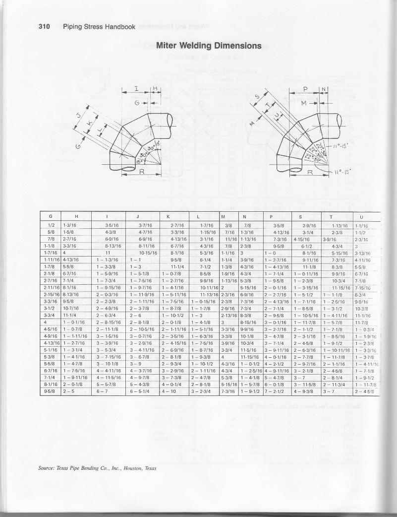
310 Piping Stress Handbook
Miter Welding Dimensions
H K M N s T
1t2 13/r6 3.5/16 3.1n6 2-1116 1-7 /16 3/a 7ta &5la 29/16 t -13/ 16 11/161-.1/2
2.3/1C
1-5/8 +Aa 4.1116 3-3/16 r.l5/ r 6 t-3116 4.13/ l6 3-114 23t81t8 2-1/16 6 9/16 69/ l6 4-13/16 3-rlr6 1ll16 1- r 3/16 7.3/16 4-15/16 3 9/r6
l- l/8 33/r 6 8,13/t 6 8.11/',r6 6-7lr6 4 3/16 7la 23tA 9-5/A 6-1/2 43/4 3
1.7116 ll lG15/16 8-1/16 5 3/16 l1l16 3 I -O 8-1/16 515/16 3.13/16q.iirrcs.slu6.7/ 16
7,rtat.'ts,1c
I 11/16 +13/ t6 1- 1-3/16 9.58 6 t/4 1-114 3 9/16 1 - 2-1t16 9.1rl16 7 3t16t7 la 5.5/8 1 - 3-3/8 l-3 1t-114 7-1/2 t.3/8 4,3/16 1 - 4.13t16 11.1t8 8 3/82-1/a 6.7 /16 r - 5-9/16 t-51/8 1-O7lA 8-5/8 t.s/16 4-3t4 '| - 7-114 r - 0-r1/16 I9/',t62.7 /16 1.1/4 1 7-314 1 - 7.5/16 '| 2-1t16 9-9/16 l.r3lr6 5-3/8 1 I5/8 1 - 2 3t4 10-3/4
211/t6 81/r6 - 9.1t16 - 4-ll16 r0 1rlr6 2 515/16 2- 0-1/16 r 1-15/r62.15/16 8, t 3/16 2 - G3/16 r - t1-9/16 r - 5lr/16 11-13/16 2-3t16 6-3/t6 2 - 2-7t16 1- 5.112 1,11t4 q 914
e:9/16
lo 3,/8
t 1:1/l611.7tB
3-3/16 $5/8 2 - 2.3t4 1 - 7.5t16 1 - Gr5/16 2.3/a 7-3/t6 2 - 4.13/16 1 ,7.1t16 \- 2:9t16 ,1 - 3.11210.7 t16 2 +9t16 2 3 7tA 1 A-7 la 1 - t-7 /8 2.9t16 7.3/4 2 - 7.1t4 | 8,5/8
3.3/4 11-114 2- 6.3t4 1 - 1C1t2 2.13n6 8.3/8 2 S-a/a I 10,5/16
4 1 0-1/16 2 - a.1la 2 - O.1/8 1 - +1/A 3 8-15/16 3 - Or/16 1- 11-1t8 1 - 5.1t4+5/16 1-O.7la 2 - 11.1|a 2 - rG5/r6 2 - 1, t1t16 3,3/16 I9/16 3 - 2-1116 2 - 1-112 1 - 7.1/a 1 0.3/4
+gfi6 1 - 1.11/16 3 - 0-7116 2- 3-5/16 3-3/8 1G r/8 3 - 4-7/a 1 8,5/16 1- 1.9/1C
413/16 1-2-7/16 3 3,9/t6 3 29/16 2 - +15t16 3-9/16 1G3/4 3- 7 1t4 2 - 4-5/A 1 9- 12 1-23!a1 - 3.3/1€5.r/16 1 - 3.114 3 - 4- 1tlt 6 2 - 6.9/16 1 - 8-7/16 3-3t4 I t-5116 I - 10.11/r6
5 3/8 1- 4-1116 3 7.15/t 6 3 6-7tA 2- 4.1/a r - 9-3/8 4 11- 15/16 4, G1/16 2 7.71A 1- 11-l ta r - 3.7/6
5.51A 1 - 4.7t4 3 - 1(}t/8 3-9 2 - S-3t4 1- 1O1/? 4 3/16 1 -O.112 4 2.1/2 2 - g-7 t16 2- 1-11t6 1 a_ 1111.
l-71l',86.7116 '| - 7.5t16 4- +t1t16 4- 3.1t16 3 - 2-9t16 2- 1-111t6 4.3/4 4- 9,11/16 2 - 4-5ta7.1t4 1 - 9-1r/16 4- t1-5/16 4-9.7lA 3 - 73ta 2- 4-7 tA 5-3/8 1 - 4-1/8 5 - 4-7la 3-7 2 A 1t4 1-9.1/28-1/r6 2 - O.1lA 5-5-7tA 5 4,3/8 4 0-1t4 2- 8-1/8 6.15/16 1 - 5-718 6 - 0-1/8 3 - 11-5/8 2 - 11.3t4 I - I1.7,t
6-7 6-51/4 4-10 3 - 2.3t4 7.3/16 1 -9.1/2 7 -2-1/2 4 - 9-3/8 3-1 2, 45ie
Source: Texas PW Bending Co., Inc., Houston, Tlxas

Weight and Dimensions of Pipe and Components 311
L€ngth of Pipe in BendsCourtesy of Crane Co.
Radiusof
Pip€Bends
540' Bends
ro nna the length of prpe in d bend havinga radius not qiven above. add together theIength of pipe in bends whose combinedradii equal the required radius.
Ersmolcr Find length of pipe in 90'bend of 5'9'radius.' Lenetli of prpA r; o0" bend of 5 radius = o+ra'Lengrh of prpc rn 90'beno of a' ,adius = W
Then, l€ngth of pipe in 90" bend of 5' 9' radius = 109rl'
f*.9\| <fS,,,) id-'l t- ILLT_\ e390" Bends | 180' Bends 270' B€nds

312 Piping Stress Handbook
Eromple No. 8-Given A, B, C, D, R
Calculation ot Pipe BendsCourtesy of Crane Co.
E : D -A _BF :YE'+ E9o : sin zc
E:D_A-BF:2N_Ce :11o"+ r'
$: tan zHK:14c
tH : lllcK:tanlH x RL:A-KP: B _KN:F*2K
Exornple No. I l--€ivcn R ond 45o Angler
B:3.414 x ^R2.828 x R0.828 x R
T = T ans.entLength oipipe in bend :
9.425 x R +27
M :llK'-n,{:sinzN
lP :90" * ZH - tNto:r4tPS:tanlOxR
C:A-2R P:2D C/2R: sin tGn _tl,op,, r--, E:D-n lH:90'+ lG
F :2E lK = 180'-2 tG
Exomple No. lO-Givan A, B, C, D, R
E=D-A-B tH:tltce -tVl-lT" K=rantHxR" v =A-K\. _ R .K= = stn ltJ ':-"- otf
x = 1ln-' - n' t?==s2o; + trIK/H : sin lL
C:%BD=R+CE = A -2R
EiF = sin lGH =%F
tJ[:tG-tLlN = r80'+2lM
4i' tso
t+A--E, l.-s1 z, -
Eromple No. 9-Given A, B, C' D, R
Erornple No. l2-Given A, R
Exomple No. l3-Given A, B, R
F =l/D'+E'

Weight and Dimensions of Pipe and Components 313
Galculation of PiPe BendsCourtesy of Crane Co.
Exomole No. 4-Givsn A, B, C' R
Exomple No.
D:B-C
F =ll aA E,I
Ii = Sln Zu
H : llr;- n'--l
fxomple N
D: B -CE:A -RF :lo, + o'EF=s:nz\lH : lr'- n'
D:B -CE:la'+aA
E --'-'
F = stn zrlS: tP * tGtK : 9O" - tStL : t4 tS_M = rar] lL xt(N:H+MO:B_C-M
LU:sinzF H:tanlGtG:y2tF P:C -H
D:B-CE:V a'+ D'
Xft
€xonple No. S-Given A, R(1
B =2R - A c :y (2R)" - B' lp: sin tD
7:sinlPt8:zP+tGlK:9O' - lSlL : 1/2 lSM=tanlLY,RN:H+MO :B -C _M
C:thBD: t4AE:IC'+ U
D
E --'--G =%E
lH:90" - tFA, + R1
-' 4A| _ rtl
Exomple No. Z-Given A, B, C, D, R
E =D -A-B G/H:sinlK IIlL=sintNtG:%tFH:tanlGxRP :C -H
F:R-CG:n+F t':lzH to :90' - tK , t\
7p =/2 tOS:tan IPXR
l--Given A, B, C, R
No. 2--Given A, B, C, R
fxomole No. 6-Given A, B
Exomole No. 3---Given A, B, C, R
H=lE+ G" rI:V L'-R'

12Allowable Pipe Span trlormulas and Tables
Pipe-Span Stress Limits 5 WL'
In order to have a workable set ofpipe-span tables or tofind an allowable span that will require a minimum ofmanual calculations, the limit for dead load stresses is setat S1/2. This eliminates the need for checkins the sum ofthe longitudinal pressure stresses plus dead load stress.(Sr, : allowable stress at maximum temperature. ASACode 831.1 and 831.3.)
The formula used to determine the maximum soans inthe tables (Thbles 12-l through l2-9) is a mean berween auniformly loaded beam simply supported at both ends anda uniformly loaded beam with both ends fixed. This meanformula most nearly depicts the conditions actually exist-ing in a refinery. (See Figure 12-1.)
By inspection, if the two moment diagrams in Figure12-1 are superimposed, the point of the maximum bend-ing moment will still be at mid-span.
Mean= M:vz(Y.y-)A safety factor of 1.25 is required because of the dis-
crepancy between theoretical assumption ald the actualfield situation.
42^M-Z
Pipe-Span Deflection Limits
M:wL'xl1245 WL2
60 wL, 5 WL2
48
In order to maintain homogeneous units, "L" must be inlb/in.; however, for ease of handling we wish to have "L"in feet and 'W" in lb/ft, which we musr now converr toinch units. Thus the preceding equation becomes:
5WI 2
M =- -48
'=!@
Maximum allowable pipe deflection between supportsmust not exceed 1 in. or ll2 the nominal pipe diameter.whichever is the smaller. This is the basic piping practice:however,.it is subject to compliance with the customer,sspecfrcanon.
The formula used to determine the deflections in Thbles12-1 through 12-9 is a mean between a uniformly loadedbeam simply supported at both ends and a uniforn rloaded beam with both ends fixed. (See Figure l2-2.)
In order to maintain homogeneous units, "Lt' must be inin. and "W" must be in lbs/in. , however, for ease of han-dling we wish to have "L" in ft and "W" in lb/ft, whicLwe must now convert to inch units. The preceding equa-tion becomes:
. wL4 l3.5WL4I28EI EI
^ 13.5WL4
EI(Text continued on Dase 3:0
48
314

a
Allowable Pipe Span Formulas and Tables 315
simply Supported Fixed Ends
frrnT1_,-N
Fixed Ends
., WL"- 2
,., - WL,rvrl - ;;
Figure 12-1. Diagram showing how stress limits are determined by figuring themean between a uniformly loaded beam supported at both ends and a uniformlyloaded beam with both ends {ixed.
Load
Shear
It t
Simply Supporled
., WLV =- 2
uoment uJf
Fixed Ends
WL4
384E1
3WL4 WL4
384E1 128E1
"'-=Y
!
r,
5WL4
384E1
Mean: =A1 +A2
Figure 12-2, Diagram showing how deflection limits are determined by figuringthe mean between a unitormly loaded beam supported al both ends and a uni-
formlv loaded beam with both ends fixed.
- z-l-- 2-l
Simply Supported

316 Piping Stress Handbook
Table 12-1Piping Spans Based on the Following carbon steel Materials: seamless A53 Gr. A, A106 Gr. A, Apt
5L Gr. A; Wetded A53 cr. B, Apt 5L Gr. B, A155 C55 Ctass 2
>200.F wilh Water, No Insulation(L = 7,650 psi)
201'F-600.F wilh Commodity = Wetghi ot Waler, Minimum Insutation(f. = 6,175 psi)
Maximum
' Exceeds maximum dettecrion.Courtesy of Po$,er Piping Company.
Tabte 12-2Piping Spans Based on the Following Stainless Steel Pipe Materials: Seamless A312 Tp316, Ag12
TP317, 4430 FP316H, A376 TP317
>200"F with Warer, No Insutarion(L = 9,375 psi)
201'F-600oF with Commodity = Weight ot Water, Minimum tnsularion(L = 8,550 psi)
PipeSize SCH.
MaximumSpan
MaximumSpan
Recommended
' Exce€ds maxiftum deflection,Co nesy of Power Piping Conpany.

Allowable Pipe Span Formulas and Tables 317
Table 12-3
Piping spans Based on the Following stainless steel Pipe Materials: seamless A213 TP304L' A312
TP3o4L, A376 TP304, A430 FP304H
>2OO'F with Waler, No Insulation(1, = 7,550 psi)
201.F-600.F with commodity = weight ol water, Minihum Insulation
(r3 = 5'800 ps4
Maximum Becommended
' Exceeds ma)(imum dellection.Courtesy of Power Piping ConPanY.
Table 12-4piping Spans Based on the Following Stainless Steel Pipe Materials: Seamless A213 TP304L' A312
TP3O4L
>2Oo"F with W.ler, No Insulaiion(1, = 7,650 Psi)
201.F-600.F wirh commodity = weigh! ol water, Minimum Insulallon
{L = a,500 Psi)
Becommended RecommendedMaximumSpan
' Exceeds maximum delleclion.Courtesy of Power PiPing Compan
MaximumSpan

318 Piping Stress Handbook
Table 12-5Piping Spans Based on the Following Nickel pipe Material: Seamless 8161 Annealed
>200'F with Water, No Insulation(L = 4,ooo psi)
201dF-450cF wlth Codmodity = Weight of Waier, Mtnlmum Insutation[. = 1,000 psl)
Maximum Recommended Maximum
Table 12-6Piping spans Based on the Following Aluminum pipe Material: seamless B24l Gr.3oo3 H112
>200'F wlth Wbter, No Insutation(1. = 4,000 psi)
201'F-400.F wilh Commodity = Wetght ot Warer, Mtnimuh tnsstation(r. = 1,7s0 psl)
Courtesy of Po,,er Piping Company.
Maximum Recommended Maximum Recommended
Cowteq of Power Piping Compaat
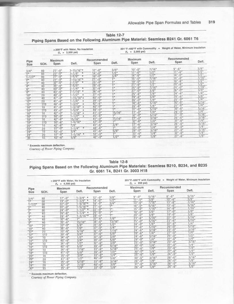
Allowable Pipe Span Formulas and Tables 319
Table 12-7
PipingspansBasedontheFo||owingA|uminumPip"M"tg'iM201.F-4O0dF with Commoclily = Weight ol Waier, Minimum lnsutalion
>2oooF with water, No Insulation(1. = 3,000 Psi) d- = 2.ooo Dsi)
MaximumSpan
RecommendedSPanPipe
SizeMaximum
scH, Span
' Exc€eds maximum dell€ction.CourresJ of Power PiPing Comqany
Table 12-8
Piping spans Based on the Following Aluminum Pipe Materials: seamless B21O' 9'234' and 8235
Gr. 6061 T4, 8241 Gr. 3003 H18
>200'F with Waler, No Insulatlon(1. = 4,500 psi)
201.F-6OO.F with Commodity = welght o, water, Minimum Insulation(t! = 9s0 psi)
Maximum BecommendedMaximum Recommenaled
' Exceeds maxlmum dellectlon.CouneE of Power Piping ComPant

320 Piping Stress Handbook
Table 12-9Piping spans Based on the Following Red Brass pipe Materiar: seamress B43
where SB : Longitudinal bending stress, psi: Maximum deflection, in.W : Weight of pipe, including commodity and
insulation if any, lb/ftL = Length of span, ftE : Hot modulus of elasticity of pipe, psiI : Moment of inertia of pipe, in.tZ : Section modulus of pipe, in.3f : Unit stress = Sr/2, psi. 56 per ASA Code
831.3
__ To solve for an allowable pipe span with a known de_
llectlon, use the foliowing lormula:
tot il.
u:o'o:offn
""""oditv = weisht ot warer' Minimum Insuration
Piping Wind Loads
Wind Loads
Tables 12-10 through 12-12 can be used to calculatewind loads.
The wind pressure (P) in lb/ff on a flat surface normalto the direction the wind for any given velocity (V) inmiles/hr is given quite accurately by the formuli
P : 0.004v,
Table 12-11 gives the pressure per square foot on a flatsurface normal to the direction of the wind for differentvelocities as calculated by the preceding formula.
The design wind pressure at the location of a givenpipeline should be applied ro the projected area ofthiout-
>200"F wilh Waler, No Insulatton(l = 1,500 psi)
Maximum Fecommended
. 4i EIAY 13.5W
Courkq of Power Piping Conpany.

Allowable Pipe Span Formulas and Tables
Il
I
side of the pipe (or insulation) to determine a uniformlydistributed load as follows:
w _ (P) (c") (D)
t44
where P : Design wind pressure, 1b/ft2
C": Shape factor (See T};ble 12-12)D : Outside diameter of pipe (or insulation)'
in.W : Wind load 0b/in) pounds per linear foot of
plpe
The design wind pressure depends on the location of the
vessel or stack. The U.S.A. Standard Building Code Re-quirements for Minimum Design Loads, in Buildings and
Other Structures, A58.1-1972, and the Uniform BuildingCode include a table showirg wind pressure at variousheights, and a map where these values apply.
More tables have been developed according to wind ve-
locity in miles/hr, wind pressure lb/ft2, wilh reference to apipe outside diameter. These tables are very usefirl forcomputer data input to model uniform wind load on pip-ins.
Table 12-10Ofticial Designations of Winds
Table 12-12Shape Factors
General UseShapeFactor
CalmLight windGentle windModerate windFresh windStrong windGaleWhole galeHurricane
* Beoufon Wind kole, U.S. Weather Burca-.
Table 12-11
Pressure per Sq Ft on a Flat Surface Normal to theDirection of the Wlnd
Velocity Pressule Corespondlng(miles/hr) (lbflrl To
Towers, stacks, drums, tanks,exchangers, prping, etc.Piers for towers and drumsTbnksOpen signsSolid signsClosed buildings, framing, andcom. partsFrames, open-type structure
Less than 1
Ito /8to12
13 to 18
19 to 24zf, to J639 ts 5455 to 75
Above 75
Cylinder
OctagonSphereFlat
0.6
0.800.601.601.401.30
1.60 Open plan0.80 Sec. plan0.00 other
Plan
10203040)U6080
100
0.41.63.66.4
10.0t4.425.640.0
Gende windFresh windStrong windGaleGaleWhole galeHurricaneViolent hurricanes

322 Piping Stress Handbook
Table 12- l3Wind Load (lb/in.)
rb/tt2 t5 20 30 35 40 45 50 55
lil il es,/ti R7! 80 85 9l to0 105 lt2 117
2.375
4.0 0
4.500
5.525
8.625
r0.750
12.7 50
I4
l820
22
24
2a
30
34
35
38
40
12
44
46
48
50
5{
55
58
60
54
56
.r4
.2t
.25
.4r
.67
,79
.47
1.00
t.r2t.25
r,37
1.50
t,62
r.7 5
r.87
2.00
2.t2
2.25
2.17
2.50
2.62
2,75
2.al
3.0 0
3.r2
3.37
3,50
3,52
3,75
3.87
4.00
4.12
.19
,29
.31
.37
. rl5
.55
.89
t.06r -15
r.33
1.4 9
1.83
1.99
2.13
2.49
2.56
2,83
2,99
3.r6
3.33
3.49
3.56
3.83
3.99
4 .16
4.33
4.49
4.66
4.83
4 .99
5.16
5.33
5.49
.24
.35
.41
.,t5
.68
.89
l.tl1.32
1.45
1.66
1.87
2.08
2.49
2.70
2.9t
3 .12
3.32
3.53
3.7 4
3.95
4.16
{.35
4 ,57
t ,74
4.99
5.20
5.40
s.6t5.82
6.24
6 .44
6.5 5
5. g5
.29
.43
.50
.56
.69
.42
r.0?
1.34
1.75
2.00
2,50
2.75
3.00
3.25
3.50
4.75
4.00
4.25
'1.504.75
5.00
5.25
5,75
6.0 0
6.25
6.75
?.00
1.25
7.50
7.75
.008
8.25
.51
.58
.65
.81
.96
1.25
1.56
2.04
2.3 3
2.62
2,9I
3.20
3.45
1.79
4.0 8
4.31
4.66
4.95
5.21
5.83
6.4I
6.70
6.99
7 .29
7 .87
8. r5
4.45
4.14
9.03
.39
.58
.75
.92
1.10
I.44
2,r2
2.3 3
2.67
3.00
3.34
4.00
4,34
4.61
s.01
5.3 4
5.0I6 -34
6.68
7 .01
7.34
7.68
8.01
8,35
8.68
9.01
9.3 5
9.58
10.02
10.35
10.68
1I.02
.55
.71
.84
1.04
1.23
I.61
2.01
t.382.61
2,99
3.35
4. rt4.48
4.85
5.51
5.9 8
6.35
6.?3
7.10
7,48
7.85
8.22
8.60
s.97
9.35
9.t2
10.09
10.47
10.84
Ll.22
tr.591r.95
12,34
.49
.83
.93
1 t5
1,38
2.39
2.9r
a,16
4.58
4.99
5.45
6.65
7 -08
7,49
7.91
8.3 3
8.?4
9.r5
9.58
9.99
10.41
10.83
1t.24
1r.66
12.08
t2.49
12.9t
13.74
.80
.9t
L.27
1.51
I.9l
1.46
2,92
4 -1,2
4.58
5.0r1
5.45
5.9S
6.41
5.8?
7.33
7 .7A
8,24
8.?0
9.15
9.62
10.0I
10.s3
l0 .99
I1.45
rl.9I\2.X7
!2.42
13.28
1.3 .7 4
14.20
14.66
15.12

Table 12'13Uniform Wind Loads (lb/ln.)
.94
1.3I
1.78
2.62
3.41
t.255.02
5.54
?.91
8.?0
9.49
10.29
r1.08
rt .8?
13.45
L1.24
15.04
17.4I
r8.20
18.99
19.79
20.58
2!.37
23 .7 4
24.53
25.L2
.98
r./15
1.66
r.87
2.76
3,59
t.17
10.83
22.50
23.22
2a.!.6
25.00
25.83
25.66
27.50
r4.16
15.0 0
15.83
17.50
19.16
20,00
20.83
.84
r.23
r. !11
2.34
3.05
3.80
l.5r{.95
?.08
7.79
8.49
9.20
9.91
10.5 2
11.33
12.03
L2.7 4
13.45
1{.1
14.87
15.28
16,99
17.?0
t8.al19.12
r9.82
2L.21
23.27
.89
r.50
2.14
4.03
4.78
5.00
8,25
9.00
9.7 5
10.50
12.00
14.25
rt.00
16.5
r 8.00
18.? 5
r9.50
20.25
21.00
2L.75
22,50
23.25
24.00
24.75
.79
l.161.33
1.49
2.20
2,47
1.21
.4.56
5.33
5.99
8.56
9.99
r0.56
11.33
11.99
13.3
13.99
t{.66
17.33
17.99
18.56
19.99
20.55
1.09
r..25
1.40
2.69
3.99
1.37
5.00
6.25
6 .87
?.50
r0.00
r0.62
r1.87
12,50
13.12
13.75
14.37
15.00
16.25
16.87
17.50
18.12
r 8,75
19.37
20.00
20.52
1.02
1.3r
t.081.65
5.83
6.41
7 .OO
?.54
8.15
10.50
II.OE
L2.23
r3.tl14.00
14.58
15.75
16.9t
.54
.9{
1.08
1.2r
t,? 9
2.33
2.91
3.45
1.33
4.8?
5.41
5.95
5.49
7.58
9.20
9.7 4
r0.29
10.83
12.45
13.54
t{.08L4.62
15.70
\5.24
15.78
17.33
!7 .A7
.59
1.00
l.l2
2.15
2.58
3.50
4.00
/t.50
5.00
5.50
6.00
6.50
7.00
?.50
8.00
8,50
9.00
10.0
II.O
r2.0
12.5
13,0
14.0
t5,0
4.00
/t.500
5 "5258.625
r0.750
I4
18
20
22
21
25
2S
30
32
34
36
40
a2
ta
45
!t5
5a
50
54

13Pipe Support Selection and Design
tions are critical (very expensive). They have been use<i
frequently in hold-down applications.t Leaf sprtngs have no known applications in the petro-
chemical industry.
Pipe Supports
Because piping is aflected by thermal expansion. sup-ports in a piping system move thermally in different direc-tions. Weight is supported by two kinds of supports-rigidand flexible.
c Rigid supports are supports in a piping system whichstay fixed. They generally move thermally in two direc-tions-horizontally and laterally, but not vertically. Theweight at this point is usually supported by shoe sup-ports, bracket supports, dummy legs, or a rigid hanger.
There are hundreds of ways these supports can be de-
signed and every company seems to have its own way.(See Figure 13- 1.)
c Flexible supports move in all three directions. Weight issupported in this application by use of spring supports.
Spring Supports
The types of springs offered for industrial support ap-
plications can be segregated into three classifications:
o CoiI spings are the springs most commonly used in thepetrochemical industry for supporting loads. They are
used almost exclusively in the construction of pre-engi-
neered and calibrated variable- and constant-supportspring hangers. They are also used in less expensrve
forms in the construction of hold downs, field supports,and vibration dampeners.
c Disc spings (BeIlviIIe springs) are seldom used in the
construction of variable- or constant-support spring
hansers, but are available if desired when space limita-
Variable Spring SuPPorts
The word "variable" in this description refers to the
fact that the load-carrying capacity of the spring varies
considerably as the spring is compressed or extended
from a fixed reference point. In other words, as the pipe
moves up, the spring is extended and the load that it exerts
is decreased. The opposite effect is experienced when the
pipe moves down. In either case, the force exerted must
not vary when extended or compressed by more than 25 %
(maximum) from the calculated load.Manufacturers offer a large variety of variable-load
spring hangers with standard and nonstandard scales. (See
Figure 13-2.) The scale is attached to the spring support
frame and indicates the vendor's recommendation forrange of load. Normally, a safety scale is provided above
and below the scale. Beyond these points the unit either
loses all load carrying capacity or it reaches its fully com-
pressed position, therefore prohibiting frrther displace-
ment. In every case, an attempt should be made to select a
spring so that the calculated load falls in the center of the
spring-scale range. The maximum deflection, which willcompute to be not more than a 25% variability, can be
found by dividing the full range of the spring scale, in
inches, by a factor of 2.5. Where the equipment loading is
sensitive or critical, larger-range scales may be beneficial
in reducing the variability percentage.
Typical applications are shown in the next pages along
with an explanation on how to size and how to determine
the type of spring to be used. Dimensions for variable
{Texl conlinued on Page 327
324

Pipe S
upport Selection and D
esign 325
oo-o-f6olo(9o.9lt
IE
HI g
E
x
o.lI
e
FI
l+lP ll.l
u_!J tl
\I
F.l
trTli
| |t / -.llI_l
olill
tlsstA
$
;
"'l1
tl
e
JJ
r.;l
!4t.,|
oR
Ifl
E",1
.i.{lc)l
\ \ET
, tf
" 6
'S+
t
ta

326
Type A
Typc C
Type E
Piping Stress Handbook
Typr F
Typr D
Typc FWirh Roller
Typo B
T=fi,t.d\V
Typr A
!tI
m
Ti|frl|\
How lo D.Lrnio. Type: The type of variable sorinehanger to be used depends upon the physical ihariacteristic-s_ reqlired by the suspension problem; i,e.,amount,9f head room, whether pipe is to be supportedabove the spring or below the spring, etc. Consldera-tion _should be given to the seven standard types of-fered (see line cuts of types ,,A', througlr',,6"r,Special variable spring hangers can be fabricated forunusual conditions.
How io Dctcrminc Sire: Conplete sizing infornation isgiven above the hanger selection chartThis information is applicable to sizing hangers ofall series.
It will be noted on the hanger selection charts thatthe total spring deflection in the casing leaves aleserve above and below the recommended workingload mnge.
Typr G
Trovol Stop:
The functional design of the pre-compressed variablespring hanger pereits the incorpo.ation of a two-piecetravel stop that locks the hanger spring against up-ward or downward movement for temporary conditionsof underload or overload, The complete travel stop,the up litnit stop only for cold set purposes or the downlimit stop only which rnay be ernployed during erection,hydrostatic test or chenical cleanout will be fumishedonly when specified. The travel stop is painted redand is installed at the fsctory with a red ..cautio!,'tag attached calling attention that the device rnust beremoved before the pipe line is put in service.
lrrtr-lPICCEI
lrnev:Lf sroP
i LrIrTlPtEqg
L--,1rH
Figu.e 13-2. variable supports. (courtesy support rechnology and piping Technology products, Inc_)

springs are generally the same for all the malufacturers.That is why loading tables and dimensions that can be
used for application in supporting piping have been in-cluded.
Constant Spring SuPPorts
The word "constant" in this description implies that the
spring will exert the same lifting effort as the pipe moves
up and down. Actually, the spring rate in most cases rs
minimized by transferring the load through a series of lev-ers so that the elongation or compression of the spring is
negligible.Constant-support spring hangers are considerably more
expensive than variables and are therefore used sparingly.
They are used in conjunction with large deflections where
variability becomes a problem, large loads where erren
small variabilities are a problem, and at strain-sensitiveequipment. (See Figure 13-3.)
Manufacturers offer a wide variety of load ranges, de-
flection ranges, and frames for their constant-supportsprings. Loading tables given in Thbles 13-1 through 13-5
and in Figures 13-3 through 13-6, generally are the same
for all the manufacturers, but dimensions are different and
should be obtained from each manufacturer. (See Figure13-7 for typical arangements of constant supports.)'
Travel Stops
All hangers have built-in stops to limit the travel at thetop and bottom to a small percentage beyond the specifiedrange. In addition, temporary stop pins are provided at theinitial travel position for the purpose of hydrostatic testingand to facilitate erection. All stops are of rugged construc-tion to withstand appreciable overloads.
It should be remembered, however, that hangers willfunction only when temporary stops are removed and thehangers load-rods are adjusted properly to enable thehanger to operate within the specified range oftravel. Anarrow traveling on a scale readily indicates the travel posi-
tion at all times.
Load Ad justment
All hangers are equipped with a load-adjusting nut thatpermits up to a 10Vo increase or a 10% decrease in load-carrying capacity. However, since all hangers are care-fully tested ald preset in the factory to specified loads, itis recommended that no field load adjusfinent be made un-til it is accurately determined that a change is necessary.Otherwise, the proper distribution of pipe stresses in thesystem may be disturbed.
Pipe Support Selection and Design 327
Standard Hangets
Load-travel data, physical design features, and dimen-sions are shown on the following pages, for conveniencein selecting the proper type and size hangers for any spe-
cific requirement. Since the load-supporting capacity of a
given size is inversely proportional to the travel function,excessive overfavel when specified may require a larger
and more costly hanger size than actually needed.
Sway Brace Support
This type of support is also a spring, but is not used totake care of the weight effect. It is recommended for con-trolling vibration, absorbing shock loading, guiding or re-straining thermal expansion, and bracing a pipe lineagainst sway. Figure 13-8 shows different sway braces
and tables for loading and sizes.
Insulated Pipe Supports and Anchorsfor Cryogenic Service
Gryogenic Pipe Supports and Hangers
The design of supports for piping used in cryogenicservice diffbrs from those designs used for standard pip-
ing. In this application the support is designed to avoidmetal-to-metal contact of the support with the pipe. Such
contact would create a heat sink whereby heat would be
transferred from the ambient environmental conditionsto the cold pipe through the metai support. To avoid thismetal-to-metal contact, a support is manufactured fromrigid polyurethane foam. Polyurethane offers both the in-
sulating properties necessary to maintain the cryogenictemperature, and also the high strength necessary to sup-
port the pipe. Figure 13-9 illustrates a typical cryogenicsupport. The insulated support is normally furnishedwith the foam, vapor barrier, protection shield, and a
galvanized cradle. These components are all adhered to-gether into a unit that is easily installed. The saddle as
ihown in this figure may be removed and replaced withother types of supports such as a pipe clamp for use withrigid and spring hangers, or with graphite teflon slideDlates.
The design of the polyurethane support includes the
following considerations:. Required insulation property (K-factor).o Thickness ofthe insulation on the remainder ofthe pip-
(Text conlinued ofl page 3,15.)

324 Piping Stress Handbook
Table 13-1Load Table for Variable Spring Supports for Selection ot Hanger Size
Lood Toblc in Poundrr lor Sclection of llonger site
Courtes! of Support Technolog, Products, Inc., and Piping Technolog)t Products, Inc.
0
3
6
1
2
21/.
3
6
I
sp.in, S.dl. - lb, p.r i.,
I
hir
il'

Pipe Support Selection and Design 329
Figure 2680
TYPE-A TY PE -8.
-
TYPE-C
Typc A rpringc are furnirhed with r threedcrl
buchirg in the toP Platc, providing for a rimplc rod
attachment for the upper connection.
Type B and C opringe are furnished with one ot
two luge ae ehown, welded to tlre toP cap of epring'
ha|t9al!12a
naiadloadtb
ugtPFO6rn
tb
rdalza
R.H.thdlgth
tu9holc3l2a
cadn0lengtn
crdngdlan
c
thrlrdd.plrr
6
h.i9hlolptnlt
snrFpln9
l.ngthx R
d6vl3op€n-
|n9s
ihlck-nelS
T
loedodlenglh
xmtn
0o1o20
't 00124
7
c
V2
v,V2
58s/,e 4
tht 1Y2't1h
1lz
101/rs1013/re
1Ua
1l/alUr
7h
lk7/a
Va
10,/rs115 6
131/ro131316
3'o4o
166
29C14l5
v2th
55
ash
5s/rsSs/r s
,lr 1V21V2
1V2
1013/rs115/rs121/^
11/4
1U411/a
1/a
t/s
7/e
V4
V4
115/,0
125h
1313/,e14s/ro1sYa
6o7g80
399532713
2729
Vr
5 813/rsgqa
1O1/.
6%6%
tttt!,t
11/2
11/2
11/2
1213%137/s
1Ua
1Ua
U1
121/B
1st/g14rh
1516%167/a
9o10o1lo
95012351615
62Ya3/tt/.
66
1\h
1Ol/s12Vs
9154e
8%8%8%
'|
1''|
11/2
1V22
14V21Sla147/a
11/4
1U41Ya
1U411/^ 16la
15%
17Y218Ya177e
12013o146
213428503aoo
6179a4
1
1Vs11h
77
11/1
th1
1oe/r o
13Ys13U1
askash85/6
15%s187/rs187ls
11/2
1V211/2
1rb ,21/2
1515he1815/rs181s/rs
187ll.^2171rc
15o16o170
51307125q5fl0
100124154
lU!1V214t
7Ia
1V2
1Ya
1sqa161/rs18V^
8%8%as's
't%19t
3
2011ha2315h6263lta
22Y22V2
%qa
C^
2131le2471rc26rri,e
23111le261s/ro2#l'a
18o19o200
126451680s22325
3013,18456
22U1
21/,
II
t02%27/a
181/a
n23tr
12Ve
12Ya129a
2Vt2Y. 41/2
4Y2
2811rc313i ro35rrAa
334
27/s
31h33h
Ya
le28sh6311'/re363/,c
31r463431rc3811/,4
21o 2968819591
528684
2!e 1011
3Ys 265/r s
32%12qa1zEa
2U,3
41/2 3813/rs45r1/16
3%37/a
1
1
395/15463/rs
4113/r o
48rr/16
Figure 13€, Spring supports. (Courtesy Support Technology Products, Inc. and Piping Technology Products, Inc')

TYPT-T
E- --,c=_:
Type D spring permits adjustment from the top, by lurning lhe nuls on the hanger rod against a piece ottubing. The tubing is securely welded to the spring cap. Type D spring is set above the supporting steet_Type E permits rod adjustment from either above or below the spring.
Type F spring assembly is designed to suppofi piping lrom below, direclly lrom the tloorAdjustment is made by inserting a bar into holes in the load column. and turning the load column as a jack
screw The base plate is welded to the case and has lour holes for fastening.
330 Piping Stress Handbook
TYPE-DFigure 2680
TY PE-F
J
type FT
.-- rl
csBlngLnglh
a
cr3lng
K
!hipplngl.ngth
.l
h.ighl
Mranglh
lenglhL nrngo
fr6n9.
nan9.bolta
thlck-
fian96nrng.
0o1020
6r1/,0
8s/,a
4
4
9'3/,61011/ro
3Vs
3Ys 1211h69r^6
7|h7Vz7\k
777
AY.AY.eY.
t{tt
Y. 3i3 6
3o
50 8%
5s/165s/,6 11/a
1j/a
107h611r/i6 1251o
13
8is/,s9s/16
101/a
10'5/,6
121/a
7Y2
71h7r.
a%AY.AY.
Y.
Y.
U.
Y.5U.
60
80
%
5/s
813/,69Ya
1O1/a
6%6s/s67a
11/2
1Y2-lY2
123/a
131/a
333
141/a
1431a
107l*
111/e
1211$137/,013//s I I
1orh107101
Y.Y.Y.
+t+t 6V16
90100tto 7h
101h'l2Ys
9'si,^
8s8%8%
1t/a2
131k151h12151,^
333
155h16th
12'h6131r/i6'| 1V,
15rr/rs13Y2
13v413Y.131/.
1(F/1610' 3
16}t161{1Ak
Y.U2 8U.
a%aU.
120130140
1 10,/15I37s131/4
8%8%8
21h2Y2
2Y)
13'/1616Ya
333
15r3/,618%183/a
121/B
14rr/1614Ya16!r^ 5
13U.13U.13U.
1@/1610'/!6lG6
r 6,a161,16'4
Y.%
Y2
v,AY.AY.aU.
150160170 1qa
13y416th6181/6
8%a%85/s
331/2
4
169r19'/i621VE
333
197a
25%
15r^6179!197/,n
171116
19%2t,t,e
13Y.13Y.131/.
[email protected]@/'61G/r6
16V216h16Y2
Y.\,Y2
,2
A1/.
AY.AY.
18o190200
221A
21/2
1AY6
201h235h
12Ya
124b123/a
55e/,s
21Vs23%265h
333
25r1/,52gqe3231,a
191^62151'6
21\lt6 17Y.17U.17U.
15%15,1/.
159t -2%
tt7l
12\t12y212V2
21o220
21/a
3 32123/4
127e61/t 295/,6 3 35e/i 6 295116 l7U.
17U.15Y.1g/.
2 Y. tdtt
't2h12\t
Figure 13-3. Continued.

Pipe Support Selection and Design 3il li80 Figure 2680
ROO SrZ€ A', -- l
Lz
N\-c
Type G trapeze type spring assemb,y is formed by welding lwo standard spring assemblies to the ends ofa pair ot channels. Type G assembly is especially adaptable tor use where headroom is limited, lo avoidinterference, or lo accommodate unusually heavy loads.
The assembly can be furnished wiih center to center dimensions, as specified by purchaser. When order-ing Type G, divlde the total pipe load in half to select the proper spring size. Ihe travel range of the springsremain unchanged-
r
F hanger!tza
.alodload
tb(appror)each, lb
rod caslnglenglh
caslngdlamater
min threadcngegornonr channtla
P z
0o1o20
138200256
282930
V21/z
Y2
6rr/re
8s/'"
444
Ya
Ya1/a
,b
5h
1V2
1Y2
1V2
V2
3o405o
446598
3839
v2
Y2
V2
7151rc
a5h
5e/ro Ya3/a
Ya lt
2%Ya
6o708o
79810641426
63sh5k
1b
813/15
10v4
6s/a
6%6%
1
1
1
222
th7/o
9o10o110
190024703230
123137125
laUa1/g
107/a'lzYs
91s/rs
8E487a 11/re
11/a
1U.1Ya
11/4
333
t/a
7/e
12o130140
427657007600
't37175183
1
1Ya
1Va
10,/re131/s
13Y4
at6
8%
1 1Y2
11/2
1lz
1
150160170
'| 02601425019000
224270326
1U4
11/z
13/a
13/a161/relAYs
8%gVa
Bsh
11/g
231rc271rc
2Va21/e
2
18o190200
252903361044650
630
933
22U4
2V,
18Y.202316
12Ya12Ea
12/a
2131rc3r^63s/rs
2%2sh27/a
44
3e/'a21o22o 79142
11371436 3
2651rc32%
12!a1zCa
3rr/ro 3Vs
31t 44
Figure 13-3, Continued.

332 Piping Stress Handbook
TY PE-B--
Figure 980TYPE-C
-I-
rRiSrElh
stzE'A'
Type A springs are furnished with a threaded bushing in the top plate, providing for a sjmple rod attach-ment for the uDoer connection.
Type B and C springs are unfurnished with one or two iugs as shown, welded to the top cap of spring.These types are designed for use where headroom is limited, as these springs can be attached direc y to
building steel by a pair of angles, eye rod or a single plate.\l
BAa,co,Ec
rypr A, C r.ltht (rppror) lb, {ch
||,!Llgll
H Rhga
lhlct
Ia,c
tP.
La.c D,Eoolo20 ].t
12rl149t1srh
1I4
ththth
l11Y.
lu.
,^,hrh
U.
U.
161/,3
is3 6
2111$2.t$
18u/r62Vlft
23\'l255^.
14Y.
15'V,l16U.171.1
197/l
'tl13t5
'tlt315
t920 39
4330405O
t415Y.
r6lt 5r/rr
ththllt
tY.1Y.
1U.h,^
15..
18'/,r
2O.l$22tl$?35 . 211he
2*h.
26r/'e
r stt16?h
1AU.
l7+f1At/.
20L
m2325
19221
333739
5t576l
6o7080
lttt+t
ld'/rr18tli9.
6tr6516tt
lhlhth
1U.
1k1Y.
Y.
Y.
l8%*f21V.
23.h25tr261n
21
?31h73th
26rt2a%2A?h
't81r
m'l162-lU.
20"'
23Y.
384658
374549
6972
67't(B
127
9o1001lo
L,A
?0'h.2Alr8U.
81i851a9i lr
't ltllt2
1U.
1V.
1Y.
1Y.'lY. ,h
ri
2lt.h.2qh.2ovr
26i'hla,t$
yr
241'h.27'h.a\
29irl!
28tt
21Y.24'h.l9i3/rr
AV.263h1211't
87t(X
u9a
126140
124
'187
2.1189
120't3 0t40
Ilttltl
lgrt241124h
811
8tl8tl
1Y.1}|1lt 3
thth'| tl
1tlh
21'lr.A.h.26rVl
2631rr
315/r6
3r,rn.
2411hl30r!nr3131r
29rr/'l3511,r36t/r3
211h.263ha26ttt
23tlt28'lr2A'hl
134t43
94t29t37
134171174
2132853o:l
150160170
1U.
llt'lx
25Y.4hv
6l81r8St
th131
22h2h
2rr*t
ttLU.
8%3|1437tr
39Y.38lt42y
8Y.381r€r
8Y.,€1t1aV.
?f''ltr311rrSiVr
2Ahl33pir3Flr
r5820425S
149t8an3
14727273
3421|:|4
54418,o190no
22Y.2U
3(|lt37U.41U.
lx12Y.
1g
2tt2L
a4haw
s1
2h3lt3tr
t{$
37.ht 12'l|.46'r/,r$!rnr
4$i.57'tt
54. !629nr
34th.38'/r
3€rA! 482570772
147
693
520594n7
936I l7t1573
21o220
2*3
l€'h0r
1?g.lg. H th
511
3tt1 En.
57,t7111L
61lt75'h.
66%&)r/r
4Sl^62
51l,t64
9r0210
015t1t0
8421154
1962506
Figure 13-4, Spring supports. (Courtesy Support Technology Products, Inc. and Piping Technology Products, Inc.)
rll
I

Pipe Support Selection and Design 333
Figure 980
TYPE-D T Y PE-I
___l_
T-ffi-rI FC-t IxllEllrllLl-l-L---i
TYPE-F
***-ffj
T YPE -G
!
0o'lo20
19%21lt2.Y.
1Y.
1U.
1Y. 5h
7V2
7'h7Vr
7
77
8Y.AY.
AYa
Yr
tl
1.9001.9m1.9m
tili
th'ty'1th
301050
2OY.
2223v.
1U.
1Y. 5\t
7V2vh71h
8Y.a%AY.
Y. 2.8752.4752.475
5U.5Y.
5Y.
Y.
Ua
2
807080
23\'tr25Y.
thth1\'
5\t I
8
1oth107h1Ot/. Y.
ltlt,l
3.503.503.50
53/r.Y.
V.
II 2
90100
O
29h25Y.
1Y. 5h 13U13rl13U.
16V,16v.'16Y7
V.
4.504.504.50
9Vt8U.8u.
h
v.
1Y.
1Y.
1U.
120130140
27Y.32Y.
2Y.2h2h
stt 13%13'13U.
10e/,.
l0'/t
16v,16v.16v2
h 4.504.504.50
aU.
9U.AV.
hh
ththlVa
{4
150t60'| 70
3S'13h
3Yr5v,
13u.13%13U
l0'/,.16Y.16v,16v,
Ua
4.504.504.50
a%AY.8Vt
h 2h2\l2Vr
1{
160190200
48tl35'1. sV,r
5ra5!t
17Y.
17U.
17U.
l5Y.15Y.lsya
Y. qt 5 5635.5635.563
12v.12v.12v,
al2'h
a1
210220
m+t 6Y.6n
51{ 17v.llUa
l5V.r 5?r
222
U.* It5.5635.56:]
l2v.12/t
3}t3ti
a1
Figure 13-4. Continued.

334 Piping Stress Handbook
TYPE-B
Figure 820
TYPE-Cr-l-tTYPE-A
III'
ROD S|ZE "A" - --_<,1
__JH
ROD SIZE "A"
Type A springs are lurnished wilh a threaded bushing in the top plate, providing lor a simple rod attach-menl for the uooer connection.
Type B and C springs qre unlurnished with one or two lugs as shown, welded to the top cap of spring.These types are designed for use where headroom is limited, as these springs can be attached directly lo
building steel by a pair of angles, eye rod or a single plate.
r.rqhl {lp9ror) rb, ..ch
BA.A,C
c
lugh.bhr
in9f \E,C o,E
00
20s'g/i6
8j/re85/,6
1O'/,6
6r3i r 67
4
6
1010'
252527
30
505', 6J^G
8'/rs
9r/,6
9'/r610j/,0
61/2
61h
7 srotl
II
t0
17
t819
2931
32
6o7080
6%7th
8
BV2
8Y.
gvz
10
1OV.
lOYa
11% 8V.8%
8
8%8tk
17
m21
t819
m
4551
53
9or001to
91/,6 105/ro 13r1612tlt gv, 91/?
455245
12a€41
68 't6117
101
120130
2
3
97/r6 1215h6
15?/ro15ir/,s
103^51011$
9'1 4a5962
43
55
08718l
112134
139
r5o16()
?
3
3
3
2 2
131
127/.
14y1
16%18Y.2O1t$
171
202111 133i,6
12rs/,r71
8865T791
86
$112
172m2zla
180r90200
2
16
33
16
1913i,e 2lllt6
23
2651'a
24!.26'/,029eltt
13$/i625632()
196218zi2
210245314
488
539
210220 3
1T5
2O5116
26\ t\5288/re33'3/ro
30r^635r/re
18
22r.19
23v. 4603o940r
318it13
&71006
IB
__t
S
Figure 13-5. Spring supports. (Courtesy Support Technology Products, Inc. and Piping Technology Products, Inc.)

Figure 820
\\\
Pipe Support Selection and Design 335
ROD & NUT NOTFURNISI]EDLENGTH TO SUITCUSTOMER
TYPE.t)r-r--TYPE-E--
ROD SIZE
INDICATOF
. LOAO FLANGE NOT FUFNISHED
001020 7v,
77
7
AYa
ala YB
1.9m1 9001.9m
3i3/,e3r3^6
1
I
304050
7Ya 9Yt
8%AYa
2.4752.8752 475
5%5%5Va
I1
507080
9I9
8
II
1Ot/r
1oth1O7/.
%
h
3.503.503.50
65/,6
1
I1
2
2
2
90100110 2
13Y.13%
13%
16v216V,161/,
4.504.504.50
41.,a
8Va
S1/.
1Y.
1V.
222
120130140
13V.
13%13U.
16V.16V,16Y2
v,4.5!o
4.504.fi
8%8V.a%
1V,
1Y2
1V.
33
150160170
3
13%13V.
16Y2't6Vz
16v2
4504.504.50
aV.
8%8th
v,21h
2v.214
1
22
180190200
5 17Ul5Y.15Y.15V.
222222
5.5635 563
12V2
121h
121h
2%2rt27/.
v,
2102.O
25 17Y.17Y.
157.t 5Y.
2222 5.563
12V,12V.
3th3%
1
Figure 1&5. Continued.

336 Piping Stress Handbook
2Il2"8H THO,
SERVICE: Recommended for light loads where verti-Cal movement does not exceed 1% inches.APPROVALS: Compties with Federal SoecificationWW-H-171D (Type a9) and Manufacturers Standardi-zation Society SP-69 (Type 4B).INSTALLATION: Designed tor attachment to its sup-porting member by screwing a rod into the top cap ofthe hanger the full depth of the caD. 4'FN. TIiD
LIGHT DUTY SPRING HANGER
Corbon Steel Spring Coil ond Coge
The Light Duiy Spring Honger is used for the support of rniscelloneous lieldrun piping systems subiect to slight (up to l,/4") verticol displocement. lt isdesigned for incorporotion in rod hongers with o lood coupling provided for springIooding. lhe unit does not hove o lood scole ond trovel indicotor. Amount ofspring looding con be opproximoied by reloting "8" dimension with spring deflec-fron role.
Selection of correcl spring size is normolly done by opproximoie methodstoking into occount weight o{ pipe, covering, contents ond mojor fittings.Ordering: Order by port number ond spring size nurnber,
DIMENSION5 IN INCHES
Sl1in e
No.
ac D E Def ledion Lood
Spr in oDefle oio n
w sighrLbs.
per 100
% 6/, 2 52 26 1606'/. l'/1 66 238
l) 7)/. 5 87 2873',/, 1,/, 266 152 350
6t/, 6'/^ 2 ,4 00 200 6806 t1 81" I0'/s V/" 600 210 982
Figure 1$6. Spring supports. (Courtesy Support Technology Products, Inc. and Piping Technology Products, Inc.)

Pipe Support Selection and Design
fL. I
T+ T
----'l
.[w7-.,-es.;-
Figure 13-7. Typical arrangements oi constant supports. (Courtesy of Elcen Metal Products Company.)
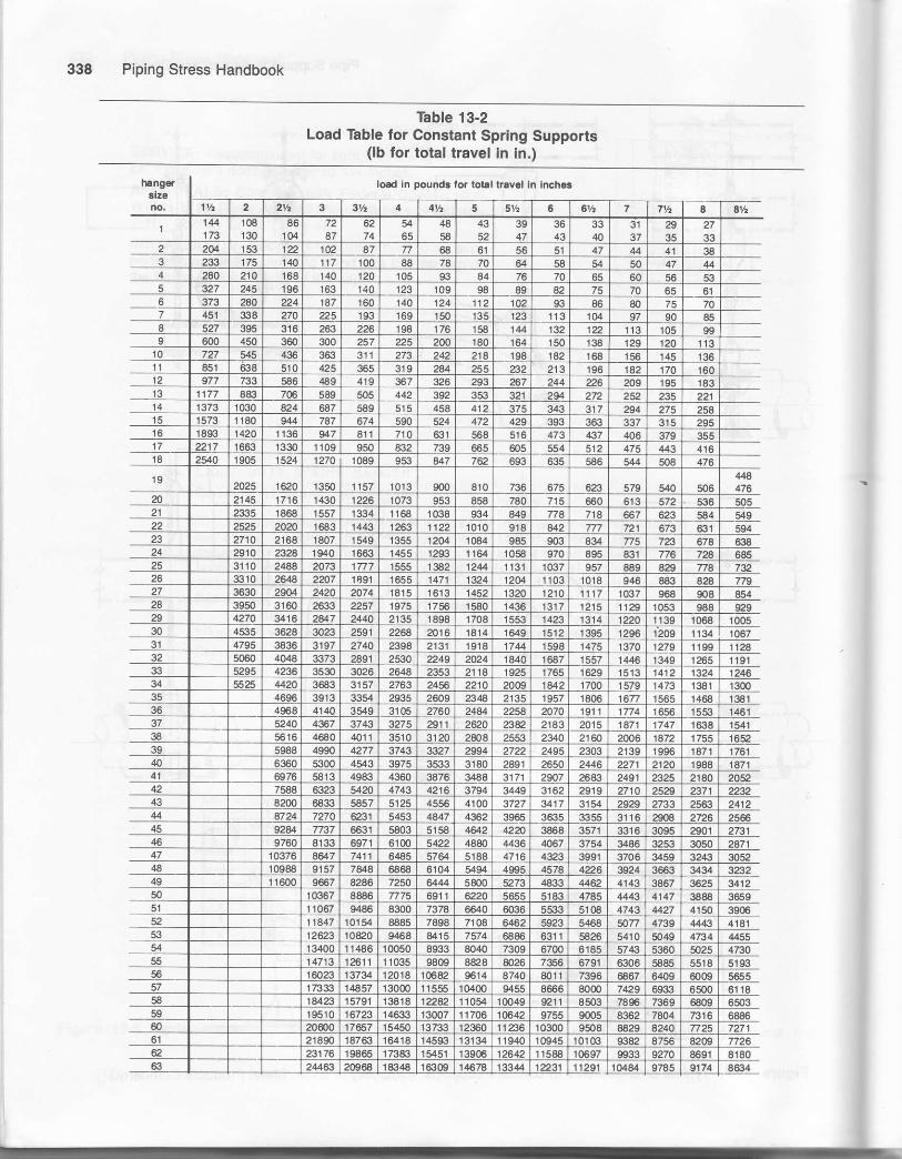
Piping Stress Handbook
Table 13-2Load Table for Constant Spring Supports
(lb for total fuavel in in.)
hango.3lzo
load in oounda for lolal truvel in lnche3

Pipe Support Selection and Design
Table 13-3Load Table for Constant Spring Supports
(lb tor total travel in in.)
losds in Dound3 lor lotal trevel in inchas

340 Piping Stress Handbook
Table 13-4Load Table for Constant Spring Supports
(lb for total travel in in.)
mn0aatrzc
load In pound! lor total lraval In Inchca
a aV. I 61h 7 7V2 I aY. I th 10 10v, l1 'fl 1{ t2
19225 17049 t 53AO 13982 i 2816 1l431 10986 10253 9613 9047 8544 8094 7drc 73?3 6990
65 201m 17866 16080 !4618 13400 12370 I1486 10720 10050 9459 8SKl3 8463 8040 7657 7308 6991 tt /u,
22064 19615 17654 16049 14711 13580 12610 1 1769 r 1094 10385 9808 9291 a8c7 8406 aa4 7675
24@3 21362 1926 17 474 16021 14790 13733 12417 r2016 r 1310 10681 '10119 9613 9r 54 8738 &359 8o1l
6a 26000 z]111 20s0 18909 17333 16m0 14a57 13866 13@O 12234 11555 10947 10400 9904 9454 9043
27635 24564 2210a 2098 1UA 1mo7 15792 1473a 13818 1300s 1282 11635 11054 1627 1004€ !t611 921 I
70 29268 26015 23414 21246 19511 18011 16725 15609 14634 13n3 13m8 12323 11707 11149 10042 10179 0756
7l 30$0 274ffi 24720 2A73 20599 19016 17657 164a0 15450 14542 13733 13010 12360 11nO 11235 10747 103(n
32835 29186 26268 23880 21889 2@O7 18763 17512 16418 1ge 14593 r 3825 13134 12508 11939 1$m 100rts
34764 30s04 27414 25286 231f7 21396 19468 18542 1/384 1636Q 15452 14639 13907 13244 12641 12f€2 11588
74 36700 p&2 29360 26691 2446'6 25a5 m972 19573 18350 17271 16311 15452 14680 13940 13344 t2764 12?63
75 38800 3/.4€9 31040 28214 aaTa 2172 20@3 19400 r8259 17244 16336 15520 14780 14r08 r3495 r2gt3
76 40900 363ss 32720 23746 27266 25170 ?3372 21813 20450 19248 18r 78 172.1 18380 15580 14471 14,25 'r3d,3
n 43000 34272 344@ 31273 28666 26462 24572 2&3 215m 20236 19111 18105 17?@ 16380 15635 1a955 l,lSilt
7a 45335 &297 36268 3297 r {22 27899 25906 24174 22864 213ii5 20149 19€8 18134 17269 1€484 15788 15ll i47ef8 42371 3a134 34668 317/9 2€K]35 27Ag 25422 ?3€B4 2432 21185 a)070 1967 18t58 17332 r65fg t5Et
& 50(100 40000 36364 33332 gT70 23572 26€66 25m0 23530 m22 21052 20@0 r9046 18r80 I ZJSO
81 52500 46666 42m0 38182 35mO 32993447
30000 27g,9 26250 24707 233:13 2105 21(!0 '| 9€8 19049 18:l€O r75aro
a5m0 48888 44@0 40000 3666 5 3t429 29333 27gO 2s883 24444 23157 mo 20951 20000 r9129 r€{xtg
8il 57500 5111 1 46000 41819 3a332 353a6 32858 30666 24750 270f0 25555 24210 2300 21903 209)7 20@0
49200 44728 409S8 37g47 35144 32799 30750 ng2 27333 25494 21500 n427 22361 21390 20500
52400 47€!7 4i1665 40309 37 429 3492 32750 30@4 29111 27574 am 24950 23816 22741 21B2
06 55400 5G64 46165 426t6 39572 3@32 34625 32589 30777 2915| 27t@ 26079 25179 24085 230P
87 584m 53091 44665 44921 41715 38032 385m 34354 32444 30736 2C200 .278o7 265,€ 253S 2/BiP
s8 61400 i5819 51165 47?32 €858 409]2 38375 36119 3t1l r 32315 s700 99236 2796 26894 25562
AE 550m 600m 54990 fi771 47144 43999 4125n 3€425 36666 3478 33otx) 31426 29997 286S4
90 61331 56617 52572 4965 4600 43295 46aA 3g/36 3€800 35045 33451 319S 3o$5
91 67164 62m2 57573 53732 5G75 47413 44777 424m 10300 38378 36633 35011 5S8C
9.s73500 6784 8 63@ I 58799 55125 51884 49O0 &20 44100 4ts5 40087 38345 5749
80830 74617 6S287 4t665 80625 57060 53848 51051 4€500 46187 4467 42t71 10416
94 87500 81540 75716 70665 66250 6235s 58848 56788 53000 50472 48177 4€G4 44135
78930 73665 6q)53 66@2 61344 58156 52615 fi222 4@r0 [email protected]
96 a2145 71a75 67649 63888 60525 57500 9757 52m8 50000 47315
97 &5360 74688 70296 66388 628q| 59750 56$0 54313 5't 953 49700
875m 82665 77500 7?943 68888 65261 620@ 5943 56358 53909 51666
85998 80625 75884 71666 64500 61423 58G31 56003 5374t
875& 8i]750 78826 74444 70524 67000 63804 m96 ws186875 81767 v21 73156 6S500 66185 43176 cx30 Stgla875m 84708 8@@ 75787 720m 64566 65444 62604
87500 83610 79210 75250 71661 68402 65430 64708
47221 82629 785m 74756 71351 68250 6ta1,l
67500 86050 81750 n851 743t 1 71c62 dJ122
i06 87500 850@ 80946 77265 739€ 70831
10787500 84469 80628 v125 73914
875m 83992 80342 770ma7446 s3646 m183
110875m 86050 830

Pipe Support Selection and Design 341
Table 13-5Load Table for Constant Spting Supports
(lb for total travel in in.)
nangJaLano.
load In pound3 ior lotll tievol In inchc
t8l2V. 13v2 14 14Ya 't5 1SV2 16 15Y2 17 llth 1AV2 le 19h m
64 6152 5915 5696 5492 5303 5126 4961 4a06
65 6432 6184 57 42 5544 5359 518 7 5025
66 7062 67$ 6538 6304 6087 5884 5694 5617
67 7@0 7394 7120 6966 6629 6408 620 r m0a
6a 8320 sm 7m3 7428 7172 6933 6709 65@
a 8843 8503 8188 7895 7623 7365) 7131 6909
m 9005 8671 8361 8073 7804 7552 7317
71 9888 9507 9155 8428 8523 8239 7973 n2572 10507 10103 9724 cts 9057 8755 4473 82G73 11126 10697 10301 9932 9590 9270 8971 8692
74 11714 1 t292 r0873 10484 10123 9786 9470 9175
12416 1r ct8 11496 11084 10703 10346 10012 9700
76 1$88 12544 12118 11584 11282 10906 10554 10225
77 !3760 13230 12740 122€4 11861 1 1466 11096 10750
78 14507 1399 13432 12951 12505 12088 11698 |l3479 15254 r4666 t 4123 13618 13149 12710 12300 11917
&) 16000 153€4 14814 fi2€4 13792 12902 125.O
81 16m0 r6153 15555 14S8 14482 14m0 1354 7 13125
8it 't7€o0 '16922 16295 15712 15171 1465s 14r92 13750
83 18400 17602 17(B6 16427 15861 15332 14lX)7 14375
u 19680 18522 142.1 1756S 16364 16398 15859 r5375
20960 20153 19406 1A712 18068 17465 16902 16375
86 22160 213o7 m517 19783 19102 18465 17869 173r3
87 23:t60 ?2461 21628 20855 20't36 19465 18A37 18250
88 24560 23614 2739 21C26 21171 20465 't9805 19188
89 26400 25384 24413 23569 2757 219e8 21288 20625
m 29440 2€3o7 2725a 26283 25377 24331 23740 23000g1 3?210 31@0 29&50 a7a2 27791 26864 25998 25188g2 35280 as22 32665 31496 301r I 29397 28449 27563
s 3aan0 37g)E 35944 34639 33446 32330 31247 3)313
91 12!00 40788 39257 37853 $549 3530 34t90 33125
95442@ 42494 40g24 39460 381m 36830 35642 34531
321 19
33482
31175
32498
3@45
31570
29442
30691
2fl647
29863
27494
29078
27179
28332
26500
27625
4amo 44ZiO 42590 41067 39652 38330 370€3 35938 34445 43822 32856 31941 31080 30262 29486 ?€750
47800 ,r5960 44257 42873 41204 39829 39545 37344 35209 35r 45 3r'141 3l}191 32295 31448 30640 ?3875
98 4SOO 47690 45023 4428[ 42755 41329 4m00 38750 37572 36468 35/27 34441 33511 32631 31794 310m
99 51600 49613 47n5 46066 44479 429S6 41609 40313 39087 37939 36855 3584t0 3/,862 3:}946 33076 32250
tm $6m 51536 49627 47451 46203 44662 43221 41A75 406m 39r09 38284 37219 36214 35a62 34358 335m
tol 55800 53459 51479 49637 47927 46329 44434 43434 42117 40880 39712 34607 37565 36578 35640 34750
102 57600 56382 5330 5142 4S51 47995 4&47 450m 4S32 42350 41141 39996 38916 37894 36922 38000
1(x, 802m 5788e 55738 53744 51892 50r 62 44544 47031 456(P 44262 429S 41801 40673 39604 385€8 37625
104 62800 60382 58 r45 54r 34 52324 50640 49063 47571 $174 44455 43607 42429 41315 &255 39250
105 65400 62882 m552 58346 56375 54495 5e737 51094 49541 4€085 46712 45412 44196 €025 11921 40875
106 68000 65382 62960 60707 58616 56661 54834 53125 51510 5mm 48569 47214 45943 44736 435€8 42500
107 700m 6€228 657m 63350 5116€ 59127 572m 55438 53752 52r 73 506a3 49273 47942 46683 454 85 44350
t0a 7"3920 7to14 68441 65992 63719 61594 59607 57750 55994 54350 52797 51328 49942 €6i]0 47343 a6200
109 70960 74m0 71255 68706 6530 u127 62059 60125 58297 5459 53439 5200 50€30 49331 48rm
1t0 80000 76920 74070 71120 64960 66€60 64510 62500 60600 58820 57140 55550 54050 52630 51280 5m00

342 Piping Stress Handbook
Figure 550
The FIG 550 vibrotion conlrol ond swoybroce presents o neol, conpoci oppeqronce
Cut.owoy section shows simplicityof exclusive .single spring design
Deflection of single spring occurswhen thrust exceeds pre.compress ion
VIBRATION COIIIROlAND SWAY BRACT
Sire Ronge: For pipe sizes 2 through 24 inch.
Service: Recommended for conttolling vibration; ab-sorbing shock loadings; guidittg or restraining themovement of pipe resulting from thermal expansionibracing a pipe line against sway.
Instollotion: Shipped ready foi installation
Adiustment The sway brace should be in the neutralposition when the system is Hot and operating, a:which time the tension test collar should be hanitight, If it is not, the sway brace should be ad-justed to the neutral position by use of the loaicoupling. The screws in the tension test colla:need not be loosened, since they serve o[ly to se-cure it to the load coupling.
Feotures:rVibration is opposed with an ilstantaneous coun-
ter foice bringing the pipe back to normal position.
rA single energr-absorbing pre-loaded spring pro-vides two way action.
o One spring saves space and simplifies design.
o Spting has 3-inch travel in either direction.
r Accurate neutral adjustment assured.
oEnclosed spring excludes ditt and gives a clear.compact aPpeaaance.
Speci{icotions: Fulfills the requirements of the ASiCode for Pressure Piping as to fabrication detailsand materials.
Tension couses dellection of sin.glo spring in opposite direction
Figure 13-8, Vibration control and sway braces. (Courtesy Support Technology and Piping Technology Produc:-.Inc.)
Fi

Pipe Support Selection and Design 343
Siue Selection: The vibration control and sway btacegives full deflection forces from 200 to 1800 poundsand has initial precomptessed spring forces from 50 to450 pounds to dampen vibrations, oppose pipe swayand absorb shock forces.
The exact amount of energy needed to control pipingshould be in proportion to the 6ass, amplitude ofmovement, and nature of disturbing forces acting onthe pipe. When it is possible to calculate the exactrestraining force required, the size of the vibrationcontrol and sway brace capable of providing this forceshould be selected.
To simplify the selection of size, engineets have de-signed the vibration control and sway brace in threesizes that are readily related to nominal pipe size. Forpipe sizes 3%-inch and smaller, the small size isrecommended; for 4 to 8-ioch, the medium size; andfor 10-inch and larger, the large srze.
Instollotion: The vibration control and sway brace isshipped ready for installation. The rod coupling rotateswith slight resistance and the tension test collar canbe rotated by hand while holding the rod couplingstatiorla!y,
lmportont: Rod lengths should be cut and final tensionadjustments made for the hot or operating position ofthe pipe. If, with the pipe in its hot position, thetension test collar can not be turned by hand or if ittums very freely, loosen the jam nut adjacent to therod coupling and rotate the coupling until the coliarcan just be turned by hand. Retighten the jam nut.
When correct tension adjustments are completed, thebtace exerts no force on the pipe in its operatingposition. Undei shut-down conditions, the braceallows the pipe to assume its cold position. It exertsa nominal cold strain force equal to the pre.load forceplus the amount of travel from the hot to cold position,times the spring scale of the particular size of thevjbratron control €nd sway brace.
vibrqtion control crnd sway brrrce
SPRING PLATEEl'lDPLATE SPR]NG PLATE
loads . weights
FtG.550
SIO JAM NIJT,'
ENDPLATE -.
rN
EE
L
FtG 555FtG 550o dimensions (inches)
1
23
56
1
1
11/a
22
36
7995
ID
tb
21o 31/,
4to I10 to 1618 to 24
rodsize,
M,ror pipesize
preload
spring
to
weight(approx)each. lb
weight(3ppror,each, lb
50150450900
13501800
200600
1800360054007200
135/o
14TB
173/4
17141.h
2011
202O3/a
241/s
2451.o2513/, o
2713 rc
13/B
15/B
15/s
21/a
21/a
2lt
177/s
185/s
22
23r3/ro
87/a
95/a
13111i2
1315
11/a
11/a
1 r3i, o
3/a
'| Y2
11/2
11/z
1
1
1
11/2
1Yz'lrz
plpe3ize,
'11/z
222
212
pipesize,
trke-oul
E
rod
E
41/z
41,'
6tb
6Ys
63/q
63/a
63/a
1,1
1
lYz112112
I1
1
11,,
11.,
1)ta
spfing
3/a
1
1
11/a
1v21t'2
11/?
2222vz21/2
232638
a298
l23456
2lo 31/2
4lo 810 to 1618 to 24
200600
1800360054007200
6s/rs6'g/,s6'g/,s
93i r691si, e
135/,s1213lz15Yz
11/a
1l/a50
150450900
13501800
24Va25283/B
295/B
31Ya
41i2
65/e
6s/s
65/s
3/a
1Y2
1
1
1
'| Y2
11/2
1\',2
77/a
77/a
7?/3g'/a
91/a
9Ya
A As specified by customer.
Figure 13-8. Continued.
,-ROD COUPLTNG
STD. JAIV NUTT
FrG. 555
33Ls

344 Piping Stress Handbook
FIG 550 A
-
**il:"1iu *ll * dimension i! 2It 0 in or les!
FIG 55OB
--recommended when W dim€nson is 2 Il I in. or rnot€
r. _ PIPE olAp
recornmended when W dimension is 2 lt 0 in, o! lo38,
FIG 555 B
-
recomm€nded when W dimeBion is 2 lt I in. or more
t
Dimenaions lor ssgemblies lor lsrger pip€ sizes dvdilobl€ on opplicalion.S€€ psrogroph "How lo sir6 qsBemblios" obove.
Figu.e 13-8, Continued.
FIG 555 A
noDLnol plpadrs
rwoy broce!l:e
tl!alqacecorior oI plpalo olltlld6 studol ptD6 cloEp
2
2%3
3%
Is%s%sr\e8Xe
456I
2
6%78,,16
sX"
l0t2l4 3
r0%rr%t2tlftr3,\"
l82024
I4tXcrs%r7%

-a-
ing system. The thickness of the polyurethane supportshould match that of the line pipe.
. Support load,o Environmental conditions-The exposed cradle may
require special coatings or galvanizing.From these design conditions, a suitable foam density
is selected for the supports. Thbles 13-6 through 13-11 in-clude some typical properties of molded rigid polyure-thane foam used to fabricate supports.
Examining these tables, it is apparent that as the foamdensity at ambient temperature is increased, both thethermal conductivity factor and the compressive strengthalso increase. At cryogenic temperatures, however,higher density rigid polyurethane foam has approxi-mately the same thermal conductivity factor as lowerdensity foam. This results from the fluorocarbon withinthe foam cells becorning a liquid at the cryogenic tem-perature, thus creating a partial vacuum. Thus the nor-mal support design procedure involves first determiningthe required K factor to insulate the piping based uponthe thickness of the matching pipe insulation. Secondly,the foam density needed to produce the required K factoris selected. Lastly, the length of the support needed tosupport the pipe is determined using the selected density.
Pipe Support Selection and Design 345
Molded rigid polyurethane foam supports may also be
used to support other types of piping systems where themedium being transferred in the pipe is to be maintainedat a high temperature and protected from a cold environ-ment. This type of application is typical of a pipelinepumping oil at a design temperature of 180'F through a
cold environment at approximately -50"F. The insulat-ing properties of the polyurethane foam are necessary tokeep oil in a low viscous state for pumping over long dis-tances. The supports for this type of application are de-
signed in the same manner as those for cryogenic appli-cations.
lnsulated Anchors
For special designs where it is necessary to anchor thepiping system, it is also necessary to avoid the metal-to-metal contact for the conditions already stated. Anchorsare fabricated for this application by foaming between anactual piece ofthe line pipe and an outerjacket. See Fig-ure 13- 10.
\
P0WERFoAM/P0WEBSLIDE Beference Guide
POLYUBETNANE FOAMsEcTloN "B.s'
Al ligure numbers ir lhis section are ava lablein any POWEFFOAM thickness, sin91e, doubleor lriple layefing lo conform to the line
AOLTEO PLATE TO STR1JCTUBE
l-g- *..o.o "*r. ro "t"r"tu".
Figure 13-9. POWERFOAM/POWERSLIDE" reference guides. (Courtesy of Power Piping Company.)

346 Piping Stress Handbook
POWERF0AM lnsulated Pipe AnchorStainless, copper andalumanum pipe can be madeinto PowERFoAM anchors.
ULTRA HIGH DENSITYPOWERFOAM
STEEL PIPE
EXACT DUPLICATEOF LINE PIPE TO BE
WELDEO TO LINE PIPE
ON/CONTRACTION
Figure 13-10. POWERFOAM" insulated pipe anchor. (Courtesy of Power Piping Company.)

Pipe Support Selection and Design 347
Table 13-6POWERFOAM- Thermal Properties
Powerloam Den3ilier Temperalurein Cenligraale TemDeralure in FahrenheilPower Input amount
ol Energy Pow€rLoss To Malntainoella "T"/2 ll. l.
Apparent ThermalConduclivity
''K" FaclorBlu. ln. Hr. Fl.2 " F
lb./cu.ll. Kq./cu. m, Hol Face Cold Face Hol Face cold Face Blu/Hr.
101014142020
160.0160.0224.O224.O320.0320.0
+43 5+42.9+41.6+42.4+44.3138.7
1S3 7162 I193.4159 6193.4157 6
-15 1
-60 0-75 9-58 4-746-59 4
110 3109 2106 I109 1
111 7101 7
-3I6.7-261 2-316.1-255.3,316.1
251 7
103.2760104 6
102.2750
26423224.925.235731 8
88.7792986860121 7
108 6
0 02130.02190.0241o.02440.02970 0321
o 1410.r52016701690.206o.223
Cou esy of Power PipW ConpanJ.
Table 13-7POWERFOAM* Physical Properties
Densilies
Srrenglh Ske.glh
EngineeringOata
SlrenglhCompressive
At Yield with aSafety Faclor
Or 5:1
Kq. PSI PSI PSI PSI PSI
t010
2020
160 0160.0224.0224.O320.0320 0
-256-318-256-318-256,318
160194.5160194.5r60194 5
6060606.06.06.0
152152152152152152
5900450092009200r 460018000
267624414173417365228165
262525503575280042043900
I19111571667127019051315
53440883383313221630
3829595993115
234231333254380354
17
23
2725
2.81.93.1
3.2324.8
195002210427200270044000034900
137114831912189828122453
106.881.6166.6166.6264.4326.0
5.7411.7111.711€.5922.92
Courtesy of Power Piping Conpan!."o*',l'-?;ly ST?31'.':Tf;",:"':$f3$'j1".'#ij::l'.'h
ar Yrerd
Table 13-8POWERFOAM" Temperature Range
Den3illeslrsrimum (Hol) Servace
TemperelureMinlmum (cryogenic) seflice
Temperalure
lb./cu. Kg./cu. m. 'c1014
20
160 0224 0320 0
+275+275,275
135r35135
425-425-425
-245,254-254
Courtesy of Power Piping Compant
Data is all based on tests performed on POWERFOAIiI
made with our tormula and molding techniques.Independent testing laboratory corroborating iesl data
available upon request.
SUPPORT CONTACT60" - 30" each side ofvertical center line.
SUSTAINABLE LOAD FORMULA:
/n'D'L I lc\ = Sustainaute Loao\ 6 l\ tC = Compressive strength with safety lactorO = Ouier diameter in inchesL = Length in inches

Piping Stress Handbook
Table 13-9Engineering Data
IEIGHI OF PIPE, WATEir'rl|sutaTtol{ {PEe Footl
I
"r^"",1.375 t
PIPE Ifi
1J222
2.052
i5
192.01
5
'u 402.n
39.59
23
t7912
'.62 1323.,15
751"O
257.&A
r3233 9
"Are nol regular p pe sz6
*"SUSTAINABLE LOADS OF INSULATED PIPE SUPPORTSCOMPaESSIVE STRENGTH = 5.8 pst (.40774 Ks./Cm.t W|TH 5:1 SAFETY FACTOR FOAM BY
AMBIENT TEMP
'rrBased on ioam .c,mpresston (with a S:1 salery tacroi, tengrh ot slpports and pipe sizes.
Courtes! of Power Pipin| Company.
2 fb./cu. tl. - 32 Kg./cu. n.

-it
Pipe Support Selection and Design
Table 13-10Engineering Data
*-SUSTAINABLE LOADS OF INSULATED PIPE SUPPORTS
COMPAESSIVE STRENGTH = 13 PSI ( 9139 KS /Cm, WITH 5:1 SAFETY FACTORAMBIENT TEMP,
*rBased on loam compression (with a 5l saietv laclor) length ol supporb and pipe srzes
6 lb./cu. fi. - 96 Kg./cu. m'COMPBESSIVE STRENGTH ='I6 PSI (1.1248 KS./CM.4 WITH 5:1 SAFETY FACTOB (NON-MOLDEO FOAM AY
OTHEFS AMBIENT TEMP
"'Based on road compression (wnh a 5:1 salely lacior). length oi supports and pipe s[es
Courtesy of Power Piping Conpany.
4 lb./cu. tt. - & Kg./cu. d.

Piping Stress Handbook
Table 13-1 1
Engineering Data
-*SUSTAINABLE LOADS OF INSULATED PIPE SUPPORTSt tbJcu. fi. - 128 Kg./cu. m.
COiIPRESSIVE STRENGIII = ZI PSt (1.5466 Kg./Cm.,) WITHi:1 SAFETY FACTOR lt{ON-MoLDEo FoAM ayOTHERS AMBIEXT TEMP.
ot supporrs and pipe si:es.
fi'8as.d on foam densirios (wnh a 5r salety lacto4, iength ot supporls and pip€ sizos.
""Comprossive strength ol POWERFOAM onty.
Counesy of Power Piping Conpan!.

J
t4Fundamentals of ExPansion Joints
Nomenclature and SYmbols
Standard nomenclature used in discussing expansionjoints and the symbols used in applications drawings are
presented in Figure 14-2.
Types of Expansion Joints
The type of expansion joint used depends on the qpe ofmovement to which it will be subiected.
Single Expansion Joint
This is the simplest type of expansion joint . As its name
implies, it is constructed with one bellows and is used
mostly to absorb axial movements. A single joint can also
be used to absorb angular ald lateral movements, as wellas a combination of these three basic movements.
Figure 14-3 typifies good practice in the use of a singleexpansion joint to absorb axial movement. Note that the
expansion joint is placed between two main anchors (MA)and that it is located near one of the anchors. Q'{otice alsothat the first alignment guide (GD is placed close to thejoint. The second guide (G2) is close to the frst, and in-termediate alignment guides (G) are provided along thebalance of the line.
Double Expansion Joint
This consists of two single joints joined by a commonconnector that is anchored to a rigid part of the structureby means of an anchor support base. Double expansion
351
Thermal movements in pipelines and ducting resultfrom variations in temperature of the flowing medium orfrom variations in ambient temperature where piping isexposed to weather. If not compensated for in system de-
sign, these movements may cause high stresses, possiblyresulting in failure of the piping or connected equipment.
Compensation for thermal movement in a piping system. can be achieved by three basic methods:
1. Designing a flexible piping system that utilizeschanges of direction to absorb movement.
2. Using pipe loops or bends to absorb the movement.3. Using expansion devices, such as expansion joints,
swivel joints, ball joints, ard flexible hose.
There are two general categories of expansion joints-- the slip type and packless (or bellows) type. The packless,
corrugated metal expansion joint is most frequently used
in modern piping applications. It does not require mainte-nance, and its hherent flexibility to absorb thermal move-ments in several planes permits greater freedom in pipingdesign. The slip joint, a pair of telescoping sleeves madepressure tight by a packing gland, can absorb a greateramount of axial movement than a comparable bellows-type joint. However, it requires periodic maintenance andis restricted to axial movement only.
Types of Joint Movements
Expansion joints installed in piping systems are subjectto thee types of movement-axial movement, angular ro-tation, and lateral deflection. These movements can occurindividually or in combinations. The four examples inFigure l4-1 show how single and universal expansionioints absorb these movements.

Piping Stress Handbook
Figure 14-1. Expansion joint movements. (Courtesy of Badger Expansion Joint Company.)
joints are supplied with or without an anchor support basedepending on the customer's preference. See Figure 14-4.
A double joint is used when the axial movement to beabsorbed is too large to be handled by a single joint. Theintermediate anchor on the center nipple divides thismovement so that each bellows of the double joint is usu-ally located in the center of a pipe run: so both ends aresubjected to the same movements and have the same num-ber of corrusations.
Universal Expansion Joint
This consists of two bellows joined by a common con-nector which is not anchored to the structure. This per-
mits the universal expansion joint to absorb any combina-tion of three basic movements-axial, lateral. andangular-where these movements are too sreat to be han-dled by a single joint.
Universal joints usually have tie rods with stops thatdistribute the movement between the bellows and siabilizethe corrunon connector. The joints find increasing use insteam and hot-water distribution systems because thereare impressive cost savings for the large amounts ofmovement they can absorb with a minimum of guidingand anchoring.
Figure 14-5 illustrates a universal expansion joint usedto absorb lateral deflection in a single plan Z bend. Bothanchors are intermediate anchors because the pressureloading is absorbed by the tie rods. Only directional guid-
IAESORPTION OF AXTAL MOVEMEIiT
(SINGLE JOTNT)
ABSORPTION OF ANGULAR ROTATION(SINGLE.'OINT)
--I-t-'1+
- -lirlABSORPTION OF LATERAL DEFLECTION
AND AXIAL MOVEMENT(UNIVERSAL.JOINT)
r*F I
L EGEND
- X: COMPRESSION+X: EXTENSION
9: ANGLE OF ROTATTONY: L ATERAL DEFLEcTIoN

Fundamentals of ExDansion Joints 353
TXf--f MAIN ANcHoR
TFt . DTREcnoNAL
DMA l2\-------------1 MA|N ANcHoRDOUBLE EXPANSION JOINT
WITH INTERI\4EDIATE ANCHOR
PRESSURE BALANCEO
EXPANSION JOINT
-ffi- sTNGLE E*PANSToN JorNT
mmr
F__x--?IA
INTERMEDIATE
ANCHOR
TI
t -
\DIRECTIONAL INTERMEDIATE
m7f 'ANcHoR wtrH GUTDEDIA
l---- PrPE ALTGNMENT GUTDE
rr---r l
'" lfi:11
tEtmmmEND VIEW
SINGLE EXPANSION JOINT
WITH TIE RODS
PLANAR PIPE ALIGNMENT GUIOE
ra*/L't t )
sPRrNc suPPoRr
c-------E-------
+ P,PE REDU.ER
UNIVERSAL EXPANSION JOINT
WITH OVERALL TIE RODS
UNIV€RSAL EXPANSION IOINT
WITH SHORT TIE RODS
UNIVERSAL PRESSURE EALANCEDEXPANSION JOINT
l--'-4-Ff HTNGED EXPANSToN rorNr
GIIvIBAL EXPANSION JOINT
sroE vrEw
GUSSET
Figure 1'l-2. Expansion loint symbols. (Courtosy ol Badger Expansion Joint Company.)

Piping Stress Handbook
Figure 14-3. Single expansion joint. (Courtesy of Badger Expansion Joint Company.)
14-4. Double expansion joint. (Courtesy ot Badger Expansion Joint Company.)
-LATERAL MOVEMENT HOT
di'1il-l|l
Figure
f-I
Figure 14-5. Universal expansion joint. (Courtesyof Badger Expansion Joint Company.)
ing, if any, is required because the compressive load onthe pipe consiss onJy of the force necessary to deflect theexpansion joint.
Where dimensionally feasible, the expansion jointshould be designed to fill the entire offset les so th;t itsexpansion is absorbed within the tie rods as ixial move-ment.
Pressure Balanced Expansion Joint
This is a combination of single joints that oppose eachother in the same way the internal pressure loads opposethe other. This prevents excessive loading due to presiurethrust from being transmitted to pipe anchors, turbines, or
Figure 14-6. Pressure balance expansion joint.(Courtesy of Badger Expansion Joint Company.)
process equipment. The compressive forces of the twobellows are additive, but these are usually negligible incomparison with the pressure forces. This type ofjoint isused where a pipeline changes direction. It absorbs axialor a combination of axial and lateral movements.
_ Figure 14-6 shows a tlpical application of a pressure-balanced expansion joint for combined axial movementand lateral deflection. The anchor on the piping run andthat on the turbine are intermediate anchors, and onlv di-rectional guiding is required. By proper design. the guidedirectly above the turbine can be made to absorb the axialmovement forces of the expansion joint without transmit-ting these to the turbine. The only force imposed on theturbine is that which is required to deflect the expansionioint laterallv.

Fundamentals of Expansion Joints
Hor ----------.1Hinged Expansion Joint
This is a single expansionjoint designed to permit angu-
lar rotation in one plane only by use of a pair of pins
through hinge plates attached to the expansion joint ends.
Hinged jo-ints are used in sets of two or three to absorbpipe movement in one or more directions in a single plane
piping system. Each individual joint in the system is re-
stricted to pure angular rotation by its hinges. However,
each pair of hinged joints, separated by a section of pip-
ing, will act together to absorb lateral deflection in much
the same manner as a universal expansionjoint in a single-plane application.-
Expaniion joint hinges are designed to transmit the fu1l
pressure thrust of the expansion joint and, in addition'may be designed to support the weight of piping and
equipment, and absorb thermal loads, wind loads, and
other external forces. A hinged system permits largemovements to be absorbed with the minimal anchor
forces.Figure 14-7 illustrates a two-hinge expansion joint sys-
tem. In this application the expansion joints absorb onlythe differential vertical growth between the vessel and
pipe riser. Any horizontal movement due to piping elpq-iion, vibration, wind loads, etc. will be absorbed by bend-
ing of the vertical pipe leg. A planar guide may be in-stalled near the top of the vessel to protect the hingedjoints from wind loads at right angles to the plane of thepiping.
rA(:
Hings Expansion JointPlanar Guide
Figure 14-7. Hinged expansion joint.Badger Expansion Joint ComPanY.)
(Courtesy of
Figure 14-8. Gimbal expansion joint. (CourtesyBadger Expansion Joint Company.)
HEJ:PG:
Gimbal Expansion Joint
This is a single expaqsion joint designed to permit angu-
lar rotation in any plane by the use of two pairs of hinges
affixed to a cornmon floating gimbal ring' Unlike the
hinged joint which can absorb angular rotation in a singleplane ofun the gimbal joint can absorb angular rotation inany plane. The ability of the gimbal expansion joint to at-sorb angular rotation in any plane is most often applied by
using two gimbal joints which act together to absorb
movement. Gimbals, like hinges, are designed to transmitthe pressure thrust and are used in pairs, or in conjunctionwith a hinged joint.
Figure 14-8 illustrates a gimbal-joint application. Be-
cause pressure loading is absorbed by the gimbal struc-
ture, only intermediate anchors are required. Planar
zuides are provided to restrict the movement of each pip-ing leg. Ai in a hinged-joint installation, the location ofpipe suppo.t. is simplified by the load-carrying ability ofthe simbal.

Piping Stress Handbook
Anchors, Guides and Supports Cold Springing of Expansion Joints
Pipe Anchors
The.function of pipe anchors is to divide a pipeline intoindividual expanding sections. Since thermaj movementcannot be restrained, it is the function of pipe anchors tolimit and control the movement that expansion joints, lo_cated in the line between the anchors, must abiorb.
In some applications, major pieces of connected equip_ment such as turbines, pumps, compressors. and reaciors,lI desrgned to wlthstand the forces acting upon them. canfunction as anchors. Additional pipe ichors are com_monly located at valves, at changeJ in pipe direction, atblind ends of pipe and, at major branchionnections. ix_pansion devices must be installed in each of the pipe sec_tions to provide flexibility.
Pipe Guides
A pipe guide is a sleeve or frame fastened to a risidstructure that permits the pipeline to move onJy along-its
9wn lxls: The guide is needed to prevent the pipelinefrom buckling due to the pressure thiust or ftelbiiity ofthe expansion joint-or both.
.. A planar pipe guide is a pipe guide modified to permitlimited movement in one direction other than loneitudi_nal. It is used in "L" or "2" piping configurations (see
figurg J+j) where rhe expansion idints ar6 subiected tolateral deflection or angular rotatton.
Pipe guides should be located and spaced carefullv in apiping system. (See Figure l4-9.)
. A pipe support carries the dead weight ofthe insulation,
piping. and its contents. Pipe supports are not pipe guides.supports do not lim.it the free movement of piping or con_tribute to guiding it in any way. The recommendations forpipe anchors and guides given in this chapter represent themlrxmum requrements tor controlling pipelines contain_ing expansiotr joints. However, standard piping practiceusually requires additional pipe supports b;twe;n guides.
Forces and Moments
To calculate the loads on piping, supports, and equip-ment, the forces and moments to move an expansion jointmust be known. The expansion joint manufacturer willprovide axial, lateral, and angular spring rates.
"Cold springing" means prestraining the elements of apiping system at the time of installation so that thermalstresses occun'ing when the piping is hot are appreciablyreduced. The purposes of cold-springing expaniion jointsmay be considerably different, although the mechanics arebasically the same. Cold springing is generally applied toexpansionjoints absorbing only lateral deflection or angu-lar rotation.
Cold springing should not be confused with ..orecom-
pressing" or "presetting" an expansion joint. Tire lanerterms apply to adjusting an expansion joint in an axial di-rection to allow for specified amounts of axial compres-sion or extension without physical interference betweenthe corrugations or overextending the corrugations,yhich mighl damage them. If deshed, cold springing canbe done at the factory before shipment to facilitate instal-lation.
The endurance or cyclic life of an expansion joint is de-pendent on the maximum mnge of stress to which the bel-lows is subjected, the numerical maximum stress valuebeing a far less significant factor. Cold springing an ex-pansion joint to reduce the maximum numerical stresswould not result in any great improvement in cyclic life.There are, however, a number of other reasons for cold-springing exparsion joints as foliows:
Force Reduction
Il a wide range of applications, the force required todeflect an expansion joint is significant. Where the expan-sion joint is used to relieve the loading on sensitive equip-ment, where anchor structures are limited to extremelysmall loads, and in other similar cases, cold-springing theexpansion joint at installation can cut the maximum de-flection force in half. In some cases, a 100% cold springwill reduce deflection forces to a minimum at extremelyhigh operating temperatures.
Stability
Figure l4-1 shows the movements ofbellows due to an-gular rotation and/or lateral deflection. In both cases, oneside of the bellows is extended and the other compressed.so the bellows may become distorted when subjected to

AXIALMAXll,4UM RECOMMENDED SPACING FOR TNTERMEDIATE PIPE GUIDES
MOVEMENT ONLY (VALUES BASED ON STANDARD WEIGHT CAREON STEEL
Fundamentals of ExPansion Joints 357
PIPE )
400400
350
300
350
300
250
internal pressure. Reducing either the internal pressure orthe displacement of the corrugations will improve the sta-
bility of the expansion joint. By cold springing the expan-
sion joint 50% at installation, the maximum displacementper corrugation is cut in half and the exparsion joint is farmore stable. For this reason, where expansion joints are
subjected to large lateral deflections, or where operatingpressures are high, it is good practice to install the joint ina 50% cold-sprung condition.
200t80
Component Clearances
Where an expansion joint is furnished with internalsleeves, external covers, or tie devices spanning the be1-
lows, these components must have enough clearance toaccornrnodate the lateral deflection or angular rotation ofthe joint. The required clearance can be reduced to a mini-mum if the joint is cold sprung 50%. By this means, hter-
200r80
r60
r40
t60
r40
r20
6 roo
=a^feor..r 70elao(9 --
k--6>40CE
Fz-30
toL400 250
MAXIMUM PRESSURE-PSIG
NOTE: I.ADOIIIONAL PIPE SUPPORTS ARE USUAILY iEOUIREO A€TW€EI'I GIIIDES II{ACCORDANCE WITH STANOARO PRACTIC€.
2 ARROWS REF€R TO EXAMPLE GIVE^I IN TEXI
Figure 14-9. Spacing for guides with expansion joint. (courtesy of Badger Expansion Joint company.)

358 Piping Stress Handbook
nal sleeves of maximum diameter can be furnished, theoverall diameter of an expansion joint incorporating ex-ternal covers or tie devices minimized, and the desien ofexternal structures simplffi ed.
Use of Internal Sleeves in ExpansionJoints
. I?"r:lJ sleeves should be specified in expansion jointsln me Iollowlnq cases:
l. When smooth flow and/or minimum friction lossesare desired.
2. Where flow velocities are hish.3. Where there is a danger of pitting or erosion.4. In high-temperature applications.5. When copper bellows are used and the application is
for high-pressure drip, super-heated steam, hot wa-ter^or condensate, or where there is any possibilityof flashins.
Tie Rods, Hinges, and SimilarAccessories
In a piping system with expansion joints, it is often im-practical to provide main anchors to absorb pressurethrusts. In these cases. tie rods. hinges, or gimbals maysolve the problem as long as their attachments are de-signed to transmit the forces imposed by pressure in theexpansion joint.
Method of Attachment
Tie rods, hinges, and gimbals are attached in two basicways:
1. By a structure whose function is to transmit theloads to the pipe or equipment. This concentratedloading may introduce high localized stresses intothe prping in addition to the stresses due to internalpressufe.
2. By direct attachment to flanges, which then carrythe loads on the rods or hinges in addition to theirnormal flange load. In this method the total load is
transmitted through the flange bolts to the matingange and then to the connecting pipe.
In some instances cold springing is recommended tokeep tie rods closer to the bellows. thereby minimizingmoments. When ordering, advise if joints are to be insullated. If so, speci$ the insulation thickness, because thiswill affect the hardware desien.
. Consideration must also be-given to the crushing of pip-ing. Attachments must be designed to distribute
-the l-oid
as much as possible. In some cases it becomes necessaryto increase the thickness of the pipe wall and/or thelengths of the pipe nipples in orderlo distribute the load.
Proper design of attachments is extremely important.parJicularly for critical applications with high piessuresand temperatures. In such cases, hardware-cai cost asmuch as or mrcre than the expansion joints. For greatersystgm rgliab_ilrry, it is important that emphasis be put onengineerirg design rather than price. Upon receipt of per_unent apptlcatron data. sp€cial requirements can be deter_mlneo,
Internal sleeves should not be used where tars or otherhighly viscous fluids are nowing. il;;;;;t-";;;; Calculation of Forces and Loads'jplcking up," "coking," or "caking" and result in jointfailure..If purging will prwent these conditions, sleeves The forces or loads to be calculated for tie rods, hingesshould be used in conjunction with purging comections. and attachments are:
Pressure thrust.Force to extend or compress the expansion joint dueto thermal growth within its tied lensth.Weight of joint.Unsupported weight of prptng and insulation be-
1.2.
.'-4.
tween a pair of bellows.5. Weight of fluid carried in the joint and unsupported
piping. In large joints, consideration should be eivento the weight o[ water used in hydro testing.
6. Wind loading effects, if present.
In addition, effects of temperature and flow conditionsmust be accounted for.
Cycle Life Expectancy
- The cycle life expectancy of an expansion joint is af-fected by various factors in physical Construction. Theseare:
1. Operating pressure.2. Operating temperature.3. Bellows material.

4. The movement per corrugation.5. The thickness of the bellows.6. The center-to-center distance of the corrugations.7. Depth and shape of the corrugation.
Any change in these factors will result in a change inthe life of the expansion joht.
The life expectancy is defined as the total number ofcomplete cycles that can be expected from the expansionjoint based on data tabulated from tests performed at roomtemperature under simulated operating conditions. A cy-cle is one complete movement from the full-open to thefi.rll-closed to the full-open position. It should be noted,however, that laboratory tests rarely if ever duplicate ac-tual service conditions. Cycle life is only one factor in thedesign of an expansion joint and may be tle least impor-tant. Many life cycle tests have been conducted and ex-pansion joints can be manufactured to meet any specifica-tion. However, experience has shown that fewapplications have a real need for high cycle-life design,which adds unnecessary costs to the expansion joint.
Corrosion
Corrosion can significantly reduce the service life of anexpansion joint. The design and operating characteristicsof expansion joints are such that they may be exposed tocorrosive attack under conditions that do not affect pipingand fittings of similar materials.
Types of corrosion most frequendy experienced in ex-pansion-joint applications are as follows:
1. Stress-corrosion (a cracking of the material as theresult of a combination of stress and corrosive envi-ronment).
2. Intergranular-corrosion, characterized by a prefer-ential attack along the grain boundaries in metals.
3. Pitting, which is a localized attack on metals.4. General corrosion or the gradual eating away of the
metals in a system.5. Impingement and corrosion erosion, associated with
the impact of a liquid or gas medium on the surfaceof the material under attack.
6. Elevated temperature oxidation, most comrnonly en-countered in hot ak and exhaust lines.
The corrosion resistance of stainless steel depends onthe formation of a thin, unbroken, chromic oxide surface,which will form slowly in the atmosphere on clean stain-less steel. Particles of steel from welding spatter should be
Fundamentals of Expansion Joints 359
prevented by covering the bellows and using an antispat-ter compound when welding.
External conditions should also be considered. Externalcorrosion can result from fumes or sprays that may con-tact the bellows or in tunnel and manhole installationswhere water is allowed to collect. Direct application of in-sulation to the expansion-joint bellows and direct burial inthe ground are not recommended. Many corrosion prob-lems encountered in the field can be reduced, if not com-pletely eliminated. Where corrosion problems are com-plex, consult a qualified corrosion engineer.
Erosion
This is the mechanical wearing away of the metal sur-faces in a joint. It usually results from the irnpact of solidparticles entrained in the flowing medium. Where there isa possibility of severe erosion, such as in lines carryingabrasive media, heavy liners should be used to protect thebellows of the expansion joint.
Calculating Thermal Expansion
Metallic, packless expansion joints are normally de-signed to move in axial compression only, and unless oth-erwise specified, the minimum and installation temp€ra-tures are assumed to be 60'F.
Here is how to determine the amount of thermal expan-sion in a piping system:
Example
Assume a 10-in. steam line fabricated from carbon steelis carrying superheated steam at 300 psig and the distancebetween pipeanchors is 1,10 ft-O in. The minimum ambient temperature is 70"F and the maximum operating tem-perature is 460'F.
Sorution
From Chapter 2, Table 2-1, we find that the expansionof carbon steel pipe at 460'F is 3.25 in. per l0O ft, and at70'F the expansion per 100 ft is 0 in.
Piping Stress Handbook
Total expansion:(r4O ft) (3.2s in.) - 0 in.
-4(Tz-Tr)(Ts - Tr)
Example
Assume that the installation temperature will be 70"F.The required precompression is then calculated as fol-lows:
100: 4.55 in.
Therefore, we find that we should select an exDansionjoint that will absorb ar least 4.55 in. of axial
"o*o."._slon.
Precompression
If the minimum operating temperature is lower than theqggput d installation temperature, the expansion jointwill be subjected to both enension and compression-dur_ing^operation. Because most expansion jointjare designedto runcuon rn compression only. any expansion joint usedrn lyclr an apphcatlon must be precompressed (prior to in_stallatton) to prevent extension of the expansion joint be-yond its original. overall length.
If advised of the minimum. maximum, and installationtemperalures when the order is placed. the expansionjointwlll be tactory precompressed and may be installed as re_ceived.
In the case of expansion joints specified for low-temper-ature service only, the installation and maximum temoera-tures are normally the same. so thejoints function eniirelyin extension. Where such service conditions are clearlyspecified, the expansion joint will always be factory pre-compressed, ready for installation.
Where it is not possible to anticipate the installationtemlerature, the expansion joint may be precompressedin the field. The amount of precompression is determinedas follows:
P _ 6(70.F - 0.F) _(460"F - 0.F)
0.913 in.
Note: If the amount of precompression is very small (Vain. per corrugation or less), it may be neglected. Whenprecompression is required, remember to deduct theamount of this precompression from the normal overalllength dimensions.
D- Total amount of precompression, in.Total rated axial movement of the expan-sion joint, in.Minimum temperatureInstallation temperature determined by ac-tual temperatue reading of adjacent pip-ing. Do not use the ambient atmospherictemperature for this purpose.Maximum temDerature
Application
Pipe Anchors
The first step is to determine the tentative locations ofpipe anchors. By proper location, any piping system canbe reduced to a number of individual eipanding pipe sec-tions having relatively simple configurations. The numberand location of pipe anchors will depend upon piping con-figuration, amount of thermal expansion, the proximiry ofstructural members suitable for-use as anchors, and-thelocation ofpipe fittings, connected equipment, and branchconnections.
. Start out with the assumption that single expansionjoints in straight axial compression will provide the sim-plest and most economical layout. Wherever possible, thedistance between anchors and amount ofexpansion shouldbe kept uniform so rhat the expansion joinis used will beinterchangeable. Ib minimize the number of exDansionjoints adjust the distance between alchors so thai exoan-sion joints having a maximum number of corrugations ineach bellows (consistent with stabilitv) can be ised.
Galculation of Forces Acting on MainPipe Anchors
A main pipe anchor must be designed to withstand theforces and moments imposed upon it by each of the pipesections to which it is attached. In the case of the installa-tion illustrated in Figure 14-10, the force acting on themain anchor consists of the full line thrust due to pressure ,the force required to deflect the expansion joint, -the
rated
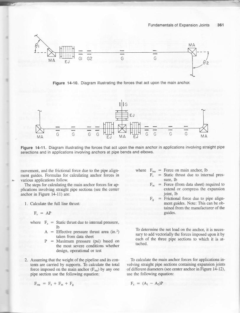
Fundamentals of Exoansion Joints
'1
0z
Figure 14-10, Diagram illustrating the forces that act upon the main anchor.
Figure 14-11. Diagram illustrating the forces that act upon the main anchor in applications involving straight pipe
selections and in applications involving anchors at pipe bends and elbows.
I
I
movement, and the frictional force due to the pipe align-ment guides. Formulas for calculating anchor forces invarious applications follow.
The steps for calculating the main anchor forces for ap-plications involving straight pipe sections (see the centeranchor in Figure 14-ll) are:
1. Calculate the firll line thrust:
F":APwhere F, : Static thrust due to internal pressure,
lbA : Effective pressure thrust area (in.2)
taken from data she€tP : Maximum pressure (p6i) based on
the most severe conditions whetherdesign, operational or test
2. Assuming that the weight of the pipeline and its con-tents are carried by supports. To calculate the totalforce imposed on the main anchor (F) by any onepipe section use the following equation:
F':F"+F.+F"
where F,nn : Force on main ancho! lbF, : Static thrust due to internal pres-
sure' lbF. : Force (ftom data sheet) required to
extend or compress the expansionjoint, lb
Fg : Frictional force due to pipe align-ment guides. Note: This can be ob-tained from the manufacturer of theguides.
To determine the net load on the anchor, it is neces-sary to add vectorially the forces imposed upon it byeach of the three pipe sections to which it is at-tached.
To calculate the main anchor forces for applications in-volving straight pipe sections containing expansion jointsofdifferent diameters (see center anchor in Figure 14-12),use the following equation:
4:(Ar-&)P
t

Piping Stress Handbook
Figure 14-12. Diagram illustrating the torces that act upon the main anchor in applications involving straight pipeselections containing expansion joints of ditferent diameters.
where A1 : Effective area, corresponding to themean diameter of the corrugations of theexpansion joint in the larger pipe section,m.'
,q.2 : Effective area, corresponding to themean diameter of the expansion joint inthe smaller pipe section, in.2
P : Maximum pressure (psi), based on themost severe conditions, whether design,operational, or test.
Here again, it is necessary to consider the differences inthe forces required to extend or compress the expansionjoints and the differences in the frictional forces due topipe alignment guides and supports. Thus, the total forceon the center anchor will be:
F,":F"+F-r+Fgr-Fgz
where F.1 = Force (from data sheet) required to ex-tend or compress the expaniion joint inthe larger pipe section, lb
F- : Force (from data sheet) required to ex-tend or compress the expansion joint inthe small pipe section, lb
Fr1 : Frictional force (from guide manufac-turer) due to pipe alignment guides in thelarger pipe section, lb
Fez : Frictional force (from guide manufac-turer) due to pipe alignment guides in thesmaller pipe section, lb
To calculation the main anchor forces for applicationsinvolving anchors at pipe bends and elbows (see Figure14-10) the following calculation must be used.
In the case of an anchor located at a pipe bend or elbow,it is necessary to consider the forces imposed by the pipesections on both sides of the anchor. Thus, assuming thateach section contains an expansion joint, the line thrustdue to pressure (F" : AP) and the forces F- and F", ex-plained previously, become biaxial components and-mustbe added vectorially. In addition, the effect at the elbow of
the centrifugal thrust (Fo) due to flow, must be consid-ered. Fo may be calculated as follows:
- 2ADV2 0rp:
-sln-where AD
eo
: Internal area of pipe, ff: DensiU of fluid, lb/ft3: Velocity of flow, ft/sec: Acceleration due to gravity, 32.2 fllsec2: Angle of pipe bend
Calculation of Intermediate Pipe AnchorForces
An intermediate pipe anchor must be designed to with-stand the force and moments imposed upon it by each ofthe pipe sections attached to it. However, an intermediateanchor does not have to be designed to withstand the fullline pressure thrust, because this force is always absorbedby main anchors or by devices on the expansion joint.such as limit rods, tie rods, gimbals, or hinges.
Assuming that the weight of the pipeline and its con-tents is caffied by supports, the following calculation willdetermine the forces acting on an intermediate pipe an-chor in a pipe section containing expansion joints (see Fig-ure 14-13):
Fre : F.r * Fr1 * Fn2 * Fgz
where F^1 = The force (ftom the data sheet) requiredto extend or compress expansion joinrEIl shown in Figure 14-13.
Frr : The total force due to friction of all thepipe alignment guides installed on thepipe section to the right of the intermedi-ate anchor in Figure 14-13.
Fno : The force required to extend or compressexpansion joint EI2 shown in Figure 14-tJ-

--363
Figure 14-13. Diagram illustrating theJorcesthat act upon an intermediate pipe anchor in a pipe section containingexpansion joints.
Fgz = The total force due to friction of all tltepipe alignment guides installed on thepipe section to the left of the intermediateanchor in Figure l4-13.
Nore: The frictional force due to pipe alignment guidescan be obtained from the manufacturer of the guides.
If the pipe is the same diameter on both sides of the in-termediate anchor, and if the guides on both pipe sectionsare similar in number and design to F,,z and Fgr, respec-tively, but opposite in sign, F1a will be equal to zero.However, it is possible that the pipeline may heat up grad-ually from one end, thereby causing one of the pipe sgc-
tions to expand before the other. It is therefore consideredgood practice to design the htermediate anchor to resistthe forces exerted by one of the two pipe sections (i.e.,F1a : F*1 *Fgr).
Pipe Guides and Guiding
A pipe alignment guide is a sleeve or frame fastened tosome rigid structure that permits the pipeline to movefreely along its own axis and limits it to this type of mo-tion. A roller support, U bolt, or pipe hanger, which orilysupports the weight ofthe pipe, cannot be substituted for apipe guide.
Pipe guides are required to prevent buckling ofthe pipe-line. Buckling is caused by compressive loading on thepipe due to the internal pressure thrust and the flexibilityof the expansion joint which causes the pipe to act like acolumn with end loading.
In axial movement applications, avoid using a singlepipe-alignment guide because such a guide may act as a
fulcrum, which might impose lateral deflection or angularrotation on the expansion joint due to movement of thepiping in a dhection other than axial.
Planar pipe guides are modified to permit limited move-ment and/or bending of the piping in one plane. These are
used only in applications involving lateral deflection orangular rotation resulting from L- or Z-shaped pipe con-figurations .
Proper alignment is very important in the installation ofall expansion joints. Expansion joints will not functionproperly unless the pipeline in which they are installed issecurely anchored and guided.
Spacing of Pipe Guides
Where an expansion joint is located close to an anchor,the first pipe guide should be located no more than fourpipe diameters ftom the moving end. The second shouldbe located no more than fourteen pipe diameters from thefirst. The recommended spacing for intermediate guidesalong the balance of the pipeline can be determined fromFigure 14-9. For any known pressure and pipe size, theguide spacing can be determined by locating the pressureon the scale at the bottom of Figue 14-9. Follow the pres-sure line vertically until it intersects the diagonal line forpipe size. From this intersection, follow across horizon-tally to the guide spacing column (left to right) and readthe recommended spacing. For example, the recom-mended intermediate guide spacing for a 6-in. pipelinecontaining an expansion joint under a pressure of 125 psigis 43 feet. The first guide should be no more than 24 in.from the expansion joint, and the second pipe guide 84 in.from the first.
Location of Expansion Joints
Wherever possible, an exparsion joint should be lo-cated irnmediately adjacent to a pipe anchor. If it is notpossible to locate the expansion joint near a pipe ancholpipe guides should be used on both sides of the expansionjoint ir accordance with the instructions given in the pre-cedhg paragraphs under "Spacing of Pipe Guides."
Fundamentals of Expansion Joints

Piping Stress Handbook
Figure 14-10 shows the preferred practice in the use ofa single expansion joint (EI) to absorb axial pipeline ex-pansion. Note the use of one expansion joint between twomain anchors (MA) , the nearness of the expansion joint toan anchor, the closeness of the fimt alignment guide (G1),the spacing between the fint alignment guide and the sec-ond alignment guide (Gr), and the spacing of intermediateguides (G) along the balance of the line.
Expansion joints should not be located immediatelydownstream from turbulence-pnrducing devices (such asbutterfly valves). plug valveJ, and su-dden increases inpipe size, mitered elbows, etc. If it is impossible to locatethe expansion joint an adequate distanceiway from tubu-lence producers. the joint slould be equipped with aheavy sleeve. Figures 14-14 and 14-15 show the informa-tion required for standard and special expansion jointsspecification sheets.
End Connections
The type of end connections selected depends upon theoperating conditions and the customer's re.guirements. SeeFigure l4-16 for illustrations. The following is a briefde-scription of the various g?es available.
Van Stoned Flanges (Type V)
The flanges are slipped over the ends ofthe bellows andthe bellows material is flared out or "Van Stoned" overthe faces of the flanges. The \r'an Stones are roughlyequivalent to the raised faces on standard forged steelflanges. The flanges are loose and free to rotate, thus per-mitting easy alignment with the mating pipeline flanges.
This construction is generally used in applications in-volving product purity or corrosion, because the only ma-terial in contact with the flowing medium is the corrosion-resistant bellows matefial.
Welding Ends (Type W)
The ends of the expansion joint are supplied with pipesuitably beveled for welding to connecting equipment orpiping. Standard joints are supplied with carbon steelweld ends. See individual data sheets for grade and type.Other thicknesses, lengths, and grades of carbon steelweld ends are available on order. Where alloy pipe isused, it may be advantageous to use weld ends that areshorter and thinner than carbon steel standards. Consultthe factory for recommendations when alloy pipe is used.
Fixed Flanges (Type SF)
The flanges are welded directly to the bellows materialwithout the use of intermediate pipe nipples. In this con-struction the flanges are in direct contact with the flowinsmedium.
Fixed Flanges (Type F)
The flanges are welded to pipe nipples, thereby provid-ing greater overall length. In this construction bbth thepipe nipple,s and flanges are in direct contact with theflowing medium.
Combination Ends
Expansion joints can be supplied with one weld end andone flanged end to meet installation requirements.
Covers
Covers protect expansion joints from mechanical dam-age and serve as a base for insulation.
Sleeves
Sleeves minimize pressure drop and also streamline theflow of gas or fluid through an expansion joint, therebyreducing friction losses and turbulence. They are recom-mended for all expansion joints, except in applicationswhere high-viscosity fluids such as tar are involved.Sleeves are required whenever the velocity of flow ex-ceeds the following values:
Nominal Medium Velocityof trlowPipe Size in Pipe
3 to 6 in. Steam 1,000 ft/min/in. dia) 6 in. Steam 6,000 ff:/min
3 to 6 in. Air 250 ft/min/in. dia(other gases)
> 6 in. Air 1,500 fl:/min(other gases)

Fundamentals ol Exoansion Joints 365
Figure 14-14. Standard expansion joint specification sheet.
For additional data use the sheet for supplemental information for special expansion joints.
CustomerProject Inquiry/Job No.
1. Item No.2. Quantrty3. Size4. Flowing Medium+5. Flow Velocity6. Int. Design Pressure, psig7. Int. Text Pressure, psig8. Maximum Temperature, "F9. Minimum Temperature, oF
10. Installation Temperature, oF
11. Axial compression, in.12. Axial extension, in.13. Lateral deflection, in.14. Angular rotation, deg.15. Pipe specification16. Weld end specification17. Flange specification18. Type or catalog number19. Internal sleeves20. External covers21. Anchor base
22. Limit rods
Use manufacturer's standard unless otherwise specified by purchaser.
23. Bellows material24. Equalizing ring material25. Total corrugations26. Lenglh limitation
If flowing medium is corrosive, erosive, or viscous explain in detail.

366 Piping Stress Handbook
Figure 14-15. Supplemental information for special expansion joints, to be used with the standard expansion iointspecitication sheet.
CustomerProject hquiry/Job No.
1. Item No.2. External design pressure, psig3. External test pressure, psig4. Pipe purge, instr. connection5. Vibration amplitude6. Vibration frequency
Special Flange Design
7. Material8. Facing9. O.D.
10. I.D.ll. Thiclness12. B.C. diameter13. No. holes14. Size holes15. Hole orientation
Design Restrictions
16. Length17. Maximum O.D.18. Minimum I.D.19. Axial force2O. LatercJ force (Shear)21. End moment22. Cychc design life23. ASME Code partial
Data forms required24. Applicable codes and
specifications

Fundamentals of Expansion Joints
Figure 14-16. End connections.

Aging-The term originally applied to the process orsometimes to the effects of allowing a metal to re-main at ordinary temperatures. H;at treatment artemperatures above room temperature for the pur-pose of accelerating changes of the type that mighttake place during aging at ordinary temperature iscalled artificial aging. The changes taking placeduring artificial aging are due to the precipitationtreatment. Aging is an approach to the attaitment ofequilibrium from an unstable condition induced by aprior operation. The fundamental reaction involvedis generally one of precipitation, sometimes submi-croscopic. The method employed to bring about ag-ing consists of exposure to a favorable temperaturesubsequent to (1) a relatively rapid cooling fromsome elevated temperature (quench aging) or (2) alimited degree of cold work (strain aging).
Alclad-The common name for a type of clad-wroughtaluminum product with coatings of high purity alu-minum; or an aluminum alloy different from thecore alloy in composition.
Alloy-A metallic substance consisting of two or moreelements, of which at least one is metal, and inwhich all elements are miscible in the molten stateand do not separate when solid.
Alloying elements-Chemical elements constitutins analloy. In steel. usually rhe elements added to mo?ifythe properties of the steel.
Annealing-A heating and controlled operation to im-part specific desirable properties generally con-cerned with subsequent fabrication of the alloy, suchas softness and ductility. When annealing followscold working for the purposes of stress removal, it iscalled stress annealing.
Arc welding-Welding accomplished by using an elec-tric arc formed between a metallic or carbon elec-trode and the metal being welded, between two sep-arate electrodes, or between two separate piecesbeing welded (also called fusion welding).
15Glossarv
.,/
Austenite-A solid solution in which gamma iron is thesolvent, having a face-centered cubic crystal struc-ture.
Austenitic steel-Steel, which due to its comoositionhas a stable structure at normal lroom) timpera-tures; as for example: the 18-8 types. It is not hard-ened by thermal treatrnent.
Bend test-A test commonly used to determine relativ!ductility of a sample by bending it over a given ra-dius and through a given angle.
BilIet-A semi-finished rolled ingot of rectangular ornearly rectangular cross section.
Brass-A copper-base alloy in which zinc is the princi-pal added element.
Brazing-Joining metals by fusion of nonferrous alloyswith melting points above 800"F but below the melr-ing point of the metals being joined.
Brinell hardness-A hardness number determined brapplying a known load to the surface of the mareriilto be tested through a hardened steel ball of knowndiameter. Note: Not suitable for measurins the hard-ness of strip and sheet because of insulfic-ient thick.ness.
Brittleness-A tendency to fracture without appreciabledeformation.
Carbon steel-Steel in which carbon provides the prop-erties without substantial amounts of other alloyinselements.
Carburizing-Diffusing carbon into the surface of iron-base alloys by heating in the presence of carbona-ceous materials.
Case hardening-Carburizing, nitriding, or cyanidinrand subsequent hardening by suitable heat trear-ment, if necessary, all or part ofthe surface portion:of a section of iron-base alloy.
Casting-Fouring molten metal into a mold or a meta.object so produced.
Cementite-An iron-carbon compound with the chem;-cal formula Fe3C often called iron carbide.
368

--
Charpy test-A pendulum-q pe impact tesr in which anotched specimen, supported ar both ends as a sim-ple beam, is broken by the impact of the falling pen-dulum. The energy absorbed in breaking the speci-men, as determined by the deireased rise of thependulum, is a measure of the impacr strength of themetal.
Chemical analysis-Separating an allor. into its compo-nent elements and identi! in-e them. In quantitativeanalysis, the proportion of each element is deter-mined.
Chromium-A hard crystalline metal used as an alloy-ing element to give resistalce to heat. corrosion, andwear and increase strength and hardenability.
Cold working-Permanent deformadon of a metal be-low its recrystallization temperature. Also definedas plastic deformation of a metal at a temperaturelow enough to ensure strain hardening. Mechanicalproperties, such as tensile strength, hardness, andductility, are also altered.
Compressive strength-The ability to withstand com-pressrve stresses.
, Compressive stress-Stress caused by a compressiveload or in fibers compressed by a bending.
Cooling stresses-Stresses caused by uneven contrac-tion, external restraint, or localized plastic deforma-tion during cooling.
Corrosion-Gradual chemical or electrochemical attackon a metal by atmosphere, moisture, or other ele-ments.
Corrosion embrittlement-Embrittlement in certain al-- loys caused by exposure to a corrosive environment.Corrosion fatigue-Combined action of corrosion and
fatigue in which local corroded areas act as stressconcentrators, causing failure at the point of stressconcentration and exposing new metal surfaces tocorrosion. The failure is progressive and rapid.
Creep-Plastic flow of metal, usually occurring at hightemperatures, subject to stress appreciably less thanits yield strength. It progresses through first, sec-ond, and third stages to fracture or results in stressrelaxation.
Cyaniding-A process of case hardening a ferrous alloyby heating in a molten cyanide salt bath, thus caus-ing the alloy to absorb carbon and nitrogen simul-taneously. Cyaniding is usually followed by quench-ing to produce a hard case.
Ductility-That property of metal which allows themetal to be permanently deformed before final rup-ture.
Elastic limit (limit of elasticity)-Maximum stress towhich a metal can be subjected without permanentdeformation at the point of stress.
Electrochemical corrosion-Localized corrosion thatresults from exposure of an assembly of dissimilar
Glossary 349
metals in contact with or coupled with one aa'drc:or of a metal containing microscopic areas di-isr::-lar in composition or structure. The dissimilar er:-ments form short-circuited electrodes. The corr.--sive medium is the electrolyte, and an electrlccurrent is induced. which results in the disolution ofthe electrode that has the more anodic solution po-tential, while the other is unattacked.
Elongation-The amount of permanent extension in thetensile test, usualll' expressed as a percentage of theoriginal gage lengrh. (e.g. , 25 percent in 2 inches).It may also refer to the amount of extension at anystage in any process which continuously elongates abody, as in rolling.
Endurance limit-A limir of stress below which metalwill withstand stress without fracture; a specifiedlarge number of applications of such stress.
Eutectoid steel-A carbon steel containine 0.80% car-bon that becomes a solid solution ar anitemoeraturein the austenite temperarure range between i ,333.Fand 2,500"F.
Fatigue-The tendency of a metal to fracture under con-ditions of repeated cyclic stressing below the ulti-mate tensile strength but above the yield strength.
Ferrite-A solid solution in which alphas iron is the sol-vent and having a body-cenrered iubic crystal struc-ture.
Ferritic steel-Steel which, due to its composition, isnot hardenable by heat trearmenr. Such stainlesstypes as 405, 430, and 448 are essentially ferriticsteels.
Free machining-The property of steel imparted by ad-ditions of sulphur, selenium, or phosphorus whichpromote chip breakage and permit increased ma-chining speeds. Additions of sulphur or seleniumalso help to decrease friction between the chips andthe tool face.
Galling-The damaging ofone or both rnetallic surfacesby removal of particles from localized areas duringsliding friction.
Galvanic corrosion-Corrosive action occurrins whentwo dissimilar metals are in contact and arJioinedby a solution capable of conducting an electric cur-rent, a condition which causes a flow of electric cur-rent and corrosion of the more anodic of the f$.ometals. (Also see Electrochemical Conosion.)
Gas welding-Welding in which heat is supplied b1' amanually or automatically controlled torch flame ofoxyacetylene or oxyhydrogen (also called fusionwelding).
Grains-Individual crystals in metal.Hardenability-In a ferrous alloy, the propern that de-
termines the depth and distribution of hardness il-duced by heat treating and quenching.

37O Piping Stress HandbooK
Hardness-Resistance to indentation by standard balls.diamonds, etc.. under standard loais. Also, the de-gree of cold working.
Heading-An upsetting process used to form rivet,screw, and bolt heads in making these products fromwire or rod.
Heat treatable-Refers to an alloy that may be hardenedby heat treatment.
Heat treatment-A combination of heating and coolingoperations timed and applied to metal or alloy toproduce desired properties.
Homogenizing-A process of heat treatment at hightemperature to eliminate or decrease chemical seg-regation by diffusion. Attainment of austenite thathas a uniform distribution of carbon.
Hooke's Law-Stress is proportional to strain in theelastic region.
Hot forming-Working operations performed on metalsheated to temperatures above room temperature.
Hot working-Hot forming above the recrystallizationrcmperature.
Hydrogen embrittlement-A brittleness sometimesengendered by contact with plating and pickling so-lution acid due to absorption of hydrogen by themetal. The embrittlement is more evident in hard-ened parts, and can be removed by aging or heatingthe steel for a prescribed period.
Hypereutectoid steels-Steels containing from 0.80%to above 2.0% carbon.
Hypoeutectoid steels-Carbon steels containing lessthan 0.80% carbon.
Impact test-A test designed to determine the energyabsorbed in fracturing a test bar at high velocity.The usual impact test specimen is a standard sizesquare bar with a V or keyhole type notch. (SeeCharpy test and Izod test.)
Intergranular corrosion-Corrosion that tends to local-ize at grain boundaries, usually under conditions ofprolonged stress and certain environments, and inassociation with poor heat reating or welding prac-tice that has caused the precipitation of a more easilyattacked constituent at these boundaries.
Izod test-A pendulum-type of notched-bar impact testin which the specimen is supported at one end as acantilever beam and the energy required to break offthe free end is used as a measure of impact strength.
Machinability-The rate and ease with which a metalcan be machined.
Magnetic particle testing-This method of inspectionconsists in suitably magnetizing the material and ap-plying a prepared magnetic powder which adheresalong lines of flux leakage. On properly magnetizedmaterial, flux leakage develops along surface non-uniformities. This method is not applicable to high
manganese or austenitic stainless steels and nonfer-rous alloys, which are nonmagnetic.
Martensite-An unstable constituent in quenched steel,the hardest of the transformation products of aus-tenite.
Martensitic steel-Steel which, due to its composition,has martensite as its chief constituent after cooling.The hardenable stainless types are all martensiteste€ls.
Mechanical prop€rties-Those pfoperties that revealthe reaction, elastic or plastic, ofa material to an ap-plied stress or that involves the relationship betweenstress and strain; for example, Young's modulus,tensile strength, fatigue limit. These properties haveoften been designated as physical properties, but theterm mechanical properties is technically more ac-curate and therefore preferred.
Modulus of rigidity-The ratio of the unit shear stressto the unit angular strain in the elastic range.
Nitriding-A process of surface hardening in which aferrous alloy is heated in an atmosphere of crackedammonia gas or other suitable nitrogenous materialthus allowing nitrogen to diffuse into the surfacametal. Nitriding is conducted at temperatures belowthe critical temperature range and produces surfacehardening of the metal without quenching.
Normalizing-A process in which steel is heated to asuitable temperature above the transformation rangeand is subsequently cooled in still air at room tei-perature. This operation is used for grain refining orto develop specified mechanical properties.
Notch sensitivity-The reduction caused in nominalstrength, impact or static, by the presence of a stressconcentration, usually expressed as the ratio of thenotched to the unnotched strength.
Permeability-Magnetic permeability is the ratio of themagnetic induction to the intensity of the magnetiz-ing field.
Physical properties-Those properties familiarly dis-cussed in physics, exclusive of those described un-der Mechanical Properties; for example, density,electrical conductivity; coefficient for thermal ex-pansion. The term has often been used to describemechanical properties, but such usage is not recom-mended.
Pickling-Immersion in dilute acid or other suitable me-dia for the removal of oxide scale from hot-rolled orotherwise sealed surfaces.
Plasticity-The ability of a metal to be deformed exten-sively without rupture.
Plating-Deposition of a thin film of a metal or alloy ona different base metal from a solution containinsions of the plating metal.

G
Poisson's ratio-Ratio expressing the relation of strainnormal to the applied load as a proportion of directstrain within the elastic limit. Also relates moduli ofelasticity ard rigidity.
hecipitation hardening-Hardening of metallic alloys,by aging, which results from the precipitation of aconstituent from a supersaturated solid solution,usually nonferrous alloys. Also termed as harden-ing. (See ,{grng.)
Process annealing-An annealing operation carried outat a constant temperature just below the criticaltransformation temperature (also referred to as sub-critical annealing) .
Proof stress-In a test, stress that will cause a specifiedpermanent set in a material, usually 17o or less.
Proportional limit-The highest stress at which the ma-terial still follows Hooke's Law, similar to elasticlimit.
Quenching-A process of rapid cooling from an ele-vated temperature.
Radiography-The use of X-rays or gamma radiation todetect internal structural defects in metal objects.
. Reduction of area-In a tensile test, the difference be-tween the original cross-sectional area and that ofthe smallest area ofthe point ofrupture. It is usuallystated as a percentage of the original area. Alsocalled contraction of area, it is not applicable to themechanical testing of sheet and strip. It is also ameasure of cold work.
Refractory metals-Metals such as tungsten, colum-bium, tantalum, and molybdenum, which have rela-
- tively high melting temperatures.Residual stress-Stresses locked in a metal after the
completion of nonuniform heating or cooling, work-ing, etc. due to expansion, contraction, phasechanges, and other phenomena.
Resistance welding-A welding process in which thework pieces are heated by the passage of an electriccurrent through the contact area, combined withpressure causing joining by fusion.
Rockwell hardness test-This test consists of forcins acone shaped diamond or hardened steel ball int6 ametal specimen to determine the degree of penetra-tion and. hence. the hardness.
Rupture stress-The true stress given by dividing theload at the moment of incipient fracture by the areasupporting that load.
Salt spray tesl-An accelerated corrosion test in whichthe metal specimens are exposed to a fine mist ofsalt water solution.
Scaling-Surface oxidation caused by heating in an ox-idizing atmosphere.
Seam welding-Resistance welding that consists of a se-ries of overlapping spots forming a continuous weld .
Glossary 37'l
Shear-Plastic deformation in which parallel planes ofmetal crystals slide so as to retain their parallel rela-tionship. Also called angular elastic strain.
Shear stress-Stress acting on a shear plane.Solution treating-A condition of complete solubility
resulting in a single phase for compositions of twoor more alloying elements at temperatures lowerthan the solids. Solid solutions may be limited in ex-tent with respect to range of alloy composition orcan be continuous, extending throughout an alloy se-ries.
Specific gravity-A numerical value representing rheweight of a given substance compared with theweight of an equal volume of water.
Spot welding-A resistance-welding process in whichthe fusion is limited to a small circular or oval area.
Stabilization-Prevention of the formation of carbidesat the grain boundaries of austenitic stainless steels.Dimensional control of nonferrous castines.
Strain-Deformation expressed in units pe-r unit oflength produced by strain.
Strain aging-Load per unit of area.Stress concentrator or stress raiser-Any notch,
scratch, sharp change of contour, slot groove, hole,defect, or other discontinuity in an engineering ma-terial that has the effect of concentratins the stressesapplied to the material or generated in-it by heatingor cooling.
Stress corrosion-Corrosive action induced and accel-erated by the presence of stresses.
Stress rupture-A test to destruction at elevated tem-perature, by which it is possible to determine thestress that causes failure at a given temperature andwith the lapse of a given period of time.
Temper-A condition produced in a metal or alloy bymechanical or thermal treatment and havins chanc-teristic structure and mechanical propertiei.
Temper brittleness-Brittleness that results when cer-tain steels are held within or slowly cooled throug! acertain range of temperature below the transforma-tion range. The brittleness is revealed by a notched-bar impact test at room temperature or lower tem-peratufes.
Tempering-The process of reheating quench hardenedor normalized steel lo a temperature belo*. t}le rars-formation range and then coolhg at an) rare de-sired. This operation is frequently called sress re-lieving. "Drawing" is synonymous xith temperhg.but the latter is the preferred usage.
Tensile strength-The maximum load il pou_n& gersquare inch, based on the origiml cro=.-^.e.-tibn.which may be developed in rensile resrilg. isee a.L:o
Uhimate Strength.)

372 Piping Stress Handbook
Thermal stresses-Stresses in metal, resulting fromnonuniform temperature distribution.
Through-hardening-Thermal description of alloysthat harden completely, so the center of a hardenedsection exhibits hardness similar to the surface.
Torsion-Strain created in an object by a twisting actionor the stresses created by such an action.
Toughnesl-Ability to absorb considerable energy be-fore fracture, usually represented by the area undera stress-strain curve and therefore involvins bothductility and strength.
[Jltimate strength-The maximum strength or stress be-fore complete failure or fracture occurs.
Vacuum melting-A process by which alloys are meltedrn a near pertect vacuum to prevent contaminationby atmospheric elements.
Vickers hardness test-An indentation hardness test uti-lizing a diamond pyrarnid and useful over the entirerange of common metals.
Welding-A process of joining metals whereby partialmelting of the parent metals occurs except in thecase of pressure welding when heating is only suffi-cient to cause recrystallization across the interface.
Yield point-The load per unit or original cross sectionat which a marked increase in deformation occurswithout increase in load. In stainless and heat-resist-ing steels, this occurs only in the martensitic andferritic chromium types. In the austenitic stainlessand heat-resisting steels, the yield point is the stresscorresponding to some definite and arbitrary totaldeformation, permanent deformation, or slope ofthe load deformation curve; this is more properlytermed the yield strength.
Yield strength-Stress corresponding to some fixedpermanent deformation such as 0.1 or 0.2% offsetfrom the modulus slooe.

aa
Index
Air-cooled heat ex changerc, 263-264Allowable expansion stress range, 2,
8-9, 11, 13Allowable external forces and
moments (tables), 264Allowable internal pressure stress,
1lAllowable loads, 257 -264Allowable longitudinal stress, 9Allowable momenlq 257 -264Allowable pipe deflection, 314Alowable pipe span, 314Allowable resultant forces and
moments (table), 258Allowable shear stress, 11Allowable span, 314Allowable stress(es), 8-11, 257 -264
range (tables), 38-111Allowable working pressure, 177,- 250-251Anchor(s), 122, 345, 356, 360-363
forces and moments, 3intermediate, 362-363main, 360-362
Angle valvescast steel, 307flanged,302
ANSI/ASME Code 816.9, 120ANSI/ASME Code B31.1 (Power
Piping), 3-6, 14, 257 , 260allowable stress range (tables),
38-'72ANSI/ASME Code 831.2 (Fuel Gas
Piping), 14ANSI/ASME Code 831.3 (Chemical
Plant and ktroleum RefineryPiping), 6-7, 14, 25'l -260
allowable stress range (tables),73-111
ANSI/ASME Code 831.4 (LiquidPetroleum Transportation PipingSystems), 7 , 9, 11, 14-15
ANSI/ASME Code 831.5(Refrigeration Piping), 15
ANSI/ASME (DOT) 831.8 Code(Gas Transmission and
Disffibution Piping), 11, 13, 15,251
ANSI/ASME Code 831.9 (BuildingServices Piping), 15
ANSI/ASME Code 831.10(Cryogenic Piping), 16
ANSI/ASME Code B31.11 (SlurryPiping), 16
ANSI/ASME Code for PressurePiping, 177
API Code 610, (steel pump force,moment, and stress limitations),257 -258
API Code 661 (design criteria forair-cooled heat exchangers),263-2&
ASME Boiler Code, 177
Barlow formula, 177Baseplate support, 258-259Bellows, 356Bellville (disc) springs, 324Bending, 123
maximum, 314stress, 1, 260
Bends, 120, 3ll-323, 350Boiler external piping, ,14
Bracket supports, 324Branch connections , ll4, 253-255Branch reinforcement, 252-256Buckling, 356, 363Building Services Piping Code
(ANSr/ASME 831.9), 15Butt-welded fittings, 303
Caking,358Centrifugal steel compressor, 262Chemical Plant and Petroleum
Refinery Piping Code (ANSI831 .3) , 6-7 , 14 , 257 -258
allowable stress range (tables),73-111
Circumferential bendhg, 123Circumferential stress, 2Coefficients of thermal expansion
(tables),2-32
Coil springs, 324Cold springing, 2-3, 356-358Combination ends, 364Compliance codes, 3- l6Components of pipe, 299-313
clearances,357Compressors, 262-263Connections
branch, 114, 253-254end,364purging, 358vertical exhaust, 260-261
Cons^TLlt sprjng supports. 327,
load table, 338-341Corrosion,359Covers, of expansion joints, 364Creep, 2, 177Cryogenic hargers, 327 , 345, 349Cryogenic Piping Code
(ANSr/ASME 831.10), 16Cycle life expectancy, 2, 358-359Cylindrical vessels, 122- 176
Deflection, 324, 329lirnits of, 314-315
Design criteriaair-cooled heat exchansers.
263-264compressors, 262-263pipe suPports, 324-350pumps,257-259turbine drivers, 260-262
Design factor F, 13Direct longitudinal sness. IDirect shear stress, 2Disc (Bellville) springs. 3?4Discharge nozzles. 257 -259Distortion energy (von Mis€sl
theory, 2DOT Code B31.8. ll. 13. 15. 51Double expansion joim- 15l-351Dummy legs, 324
Elbows, 112, 118-lllElectric generadng pla s. l-t
373
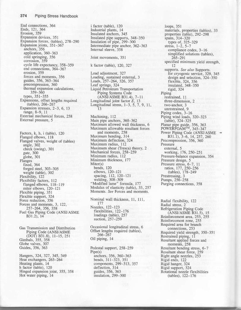
374 Piping Stress Handbook
End connections, 364Ends, 121, 364Erosion,359Expansion devices, 351Expansion forces, (tables), 278-290Expansion joints, 351-367
anchors,356application, 360-363cold springing, 356corrosion, 359cycle life expectancy, 358-359end connections, 364-367erosion,359forces and moments, 356guides, 356, 363-364precompression, 360thermal expansion calculations,
359-360types,351-355
Expansions, offset lensths reouired- (tables), 266-267'
Expansion stresses, 2-3, 6, 13range, 8-9, 11
External mechanical forces, 258External pressure, 5
Factors, k, h, i (table), 120Flanged elbows, 118Flanged valves, weight of (tables)
angle,302check (swing), 301gate,300globe,30l
Flangesfixed, 364forged steel, 303-305weight (tabl€), 302
Flexibility, 122Flexibility factors, 1 12
flanged elbows, 118- 119miter elbows, 120-121
Flexible piping, 351Flexible support, 324Force reduction, 356Forces and moments,3, 122,
257,26/.,356,358Fuel Gas Piping Code (ANSI/ASME
83r.2), 14
Gas Transmission and DistributionPiping Code (ANSI/ASME(DOT) 831.8), 11- 15, 2s1
Gimbals, 355, 358Globe valves, 307Guides, 356, 363
Hangers, 324, 327, 345, 349Heat exchangers, 263-264Heating plants, 14h factor (table), 120Hinged expansion joint, 355, 358Hot \pater piping, 14
i factor (table), 120Industrial plants, 14Insulated anchors, 345Insulated pipe supports, 348-350Insulation of pipe, 299-300Intermediate pipe anchor, 362-363Internal sleeve, 358
Joint movements, 351
k factor (table), 120, 327
Load adjustment, 327Loading, sustained external, 3Loads,257-2&, 326,357Leaf springs, 324Liquid ktroleum Transportation
Piping Systems Code(ANSUASME 831.4), 7-1r
Longitudinal joint factor t, 13Longitudinal stress, 1-3, 5,7,9, tl,
13
Machining, 112Main pipe anchors, 360-362Maximum allowed wall thickness, 6Maximum allowable resultant forces
and moments, 258Maximum bending, 314Maximum def lection, 324Maximum radius, 112Maximum shear (Tresca) theory, 2Mechanical forces, 258-259Minimum radius, 112Minimum thickness, 177Miter(s)
bends, 120elbows, 120-121spactng, 112, 120-121welding,308-309
"Modified lame" formula, 177Modulus of elasticity (table), 33,257Moments. See Forces and moments
Nominal wall thickness, 11, 111,177
Nozzles, 122-123flexibilities, 122- 176loadings (table), 257snction, 257 -259
Occasional longitudinal stress, 6Offset lengths required (tables),
266-267Oil piping, 14
Pedestal support, 258-259Pipe(s)
anchors, 356, 360-363bends,311-323,351components, 299 -313, 357deflection, 314guides,356,363insulation, 299-300
loops, 351materials, properties (tables), 33properties (table), 292 -298spans,314-320
rypes of, 325-329stress, l-2, 5-7
compliance codes, 3-16simplified solutions (tables),
265-291specified rninimum yield strength,'t2supports. See a/so Supports.
tor cryogenic service, 329, 345design and selection, 324-350flexible, 324, 356insulated, 348-350nsid, 324
Pipingrestrained, 11three-dimension, 2two-anchor, 3unrestrained,9
Piping codes, 3-16Piping wind loads, 320-323
(tzble),324-325Planar piDe euide. 356. 363POWER,FOAMTM, 345-347Fower Piping Code (ANSI/ASME -
831.1), 3-6, 14, 257 , 260Precompression, 356, 360Pressure
external, 5working, 176, 250-251
Pressure-balance expansion, 354Pressure design, 5Pressure stress, 6-7, 11
rutios, 177 , 250-256(tables), 178-249
Prestressing,3Pumps, 256-258Purging connections, 358
Radial flexibility, 122Radial stress, 2Refrigeration Piping Code
(ANSr/ASME 831.5), 15Reinforcement area, 253, 255Reinforcement zone, 255Required area for branch
connections,253Required yield strength, 350-351Restrained piping, 1lResultant applied forces and
moments, 258Resultant bending stress, 6-7Resultant shear force, 259Right angle nozzles, 253Rigid ends, 122Rigid hanger, 324Rigid support, 324Rotational nozzle flexibilities
(tzbles), 122-176
---r
{d
Saturated sream. properties of(tables). 3-l-36 -
Self sprineins. lShaft displaciment . 258-259Shape factors. 321Shoe suppon. 3!-1Shear striss- lSingle expansion ioint, 351Sleeve.356.358,364Slurry Piping Code (ANSt/ASME
831.11). t6Spans, allouable, 313. See also ptpe
sPans.Specified rninimum yield stren eth
(SMYS.,, 9, llSpring rate of nozzles, 122spnng suppons, 324_341Stabiliry,356Standard hangers, 327standard terms, 3_4Stress(es). .te€ aho piDe stress.
allowable. 8-l l. 38--l I t, 257_264deadload, 314intensificarion factors, l. I12.
I L4-121limits,314-315pressure/stress r atios, lj 7 _256prtmary, 2range, 2shear, ll
Structuraj supports, 325suctron nozzles, 257_259Supports. 324-325, 327, 342. 356.
Slee a/so Pip€(s) supports.baseplare. 258-259 -'pedasral, 258-259
Support load, 345Sustained longitudinal stress. 5)usralned-pIus_thermal expansion
stress, 6Sway brace support, 327. 342Swing check v-aives, 30g-
Temperature derating factor f, l.]terms, standard. 3_4Thermaf expansion, 2-3, 5-6. 324,
359-360
_.coefficienrs of (tabtes), 2_32r nerma movements, 351Three-dimension pipine. 2Three-weld-miter elbo;s. 12 Itte roos, JJ6Torsional stress, 2Travel stops, 327Tresca (miximum shear) theory, 2rwo-anchor Ptplng systems, 3turbines,260-267Thrbulence-producing device, 364
Uni{orm Building Code, J2lunrtorm wind loads, 323U.S.A. Standard Buildins Code
R^equirements for Deiign Loads.
Universal expansion joint, 352_J54unrestratned ptplng, g
Van Stoned flanges. 3&Variable spring iupports, 324_327
load tabte, 328
Index {IsVe. rtical exhaust connecrion. 160_16 lvrbratron control, 342_ J4.tVon Mises (distortion energr r l.betrr-2-'
Wall thickness pressure stress, 7. 251wall thlcknessmaxrmum allowable. 6nominal, l l, l12, 177required, 177
Weather,35lWedge gate valves. 306Weld elbows, l12Weld-end valves (tables)
angle,302check (swing), 301gate,300globe,301
Welding ends, 363Weld joint factor E, l0Wind loads, 320-321
(table),322-323Wind pressure, 320Working stress, 172
y values (tables), 177_250y :
Q Garlowy, 178-195, 250y = U.4 (modified lame).196_214,250
y = 0.5 (average diameter).2t4_231, t50
y : 0.7 (creep), 232_250