pipeline 101 (complete) may 2017r1 - squarespace 9. post-padding & backfilling 10.hydro-testing...
TRANSCRIPT

Pipeline 101(An Introductory to the Lifelines of Energy)
Rick RobertsAbhay Chand
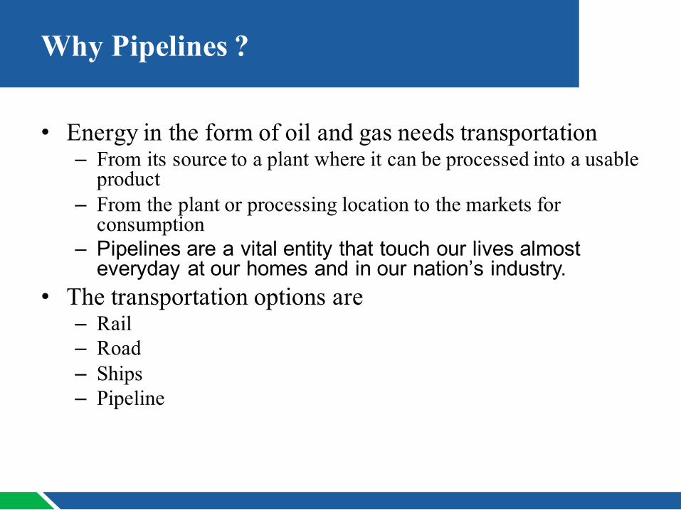
Why Pipelines ?
• Energy in the form of oil and gas needs transportation– From its source to a plant where it can be processed into a usable
product– From the plant or processing location to the markets for
consumption– Pipelines are a vital entity that touch our lives almost
everyday at our homes and in our nation’s industry. • The transportation options are
– Rail– Road– Ships– Pipeline

Why Pipelines ?
• Pipelines are by far the best option to transport these fuels both in their crude and processed forms.– Safest– Most Reliable– Economical– Can be built into inter-connected networks
• A barrel of crude oil or petroleum product shipped by pipeline reaches its destination safely more than 99.999% of the time
Why Pipelines ?
• There are approximately 2.5 million miles of pipeline crisscrossing the United States.
• These lines transport and deliver the nation’s crude oil and petroleum products such as: gasoline, diesel, jet fuel, chemicals, home heating oil and natural gas.

Delivery Systems
So what would a Natural Gas Delivery System as it exists in the
United States today, look like ?

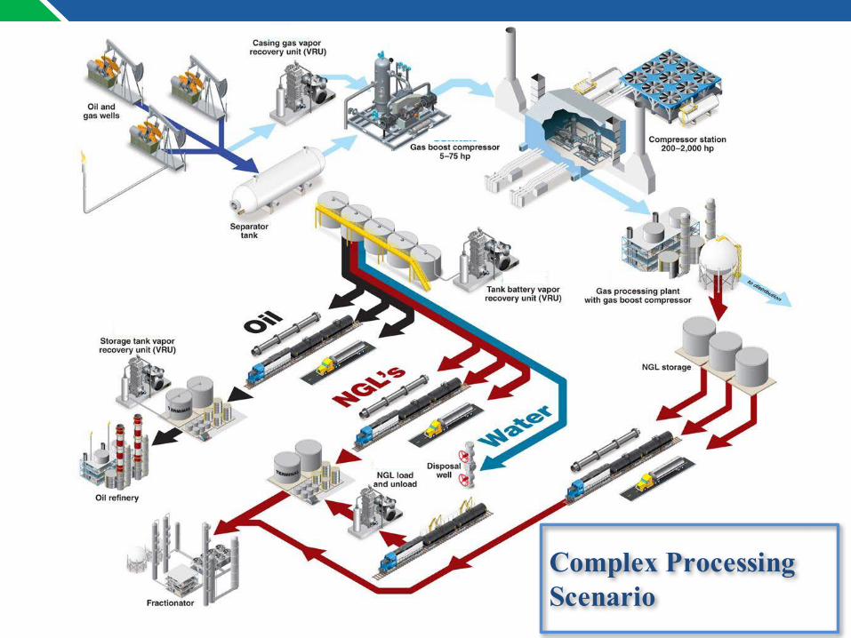
Complex Processing Scenario

What are the different types of Pipelines?
• Gathering lines• Flow lines• Transmission lines• Distribution lines
vGathering lines and transmission lines could be onshore (on land) or offshore (sub-sea)

Onshore Pipeline Construction

1. Route Survey2. ROW Clearing & Grading3. Trenching
4. Stringing5. Bending
6. Welding7. Pre-padding
8. Lowering9. Post-padding & Backfilling10.Hydro-testing
11.Block Valve Installation12.Final Grading and Full Restoration
PipelineConstructionProcessActivities
2017
Route Survey and ROW Clearing and Grading

PipelineConstructionProcessROUTESURVEY
CenterlinesurveycarriedoutonthepermanentROW(Rightofway)markedaspertherequiredspecification.Thecenterlineofrouteismarkedbyplacingstakes.
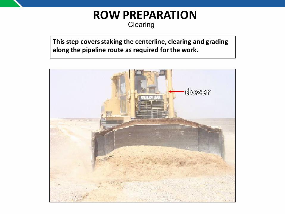
ROWPREPARATION
Thisstepcoversstakingthecenterline,clearingandgradingalongthepipelinerouteasrequiredforthework.
Clearing

ROWPREPARATIONGrading

2017
Trenching/Ditching

TRENCHING/DITCHING
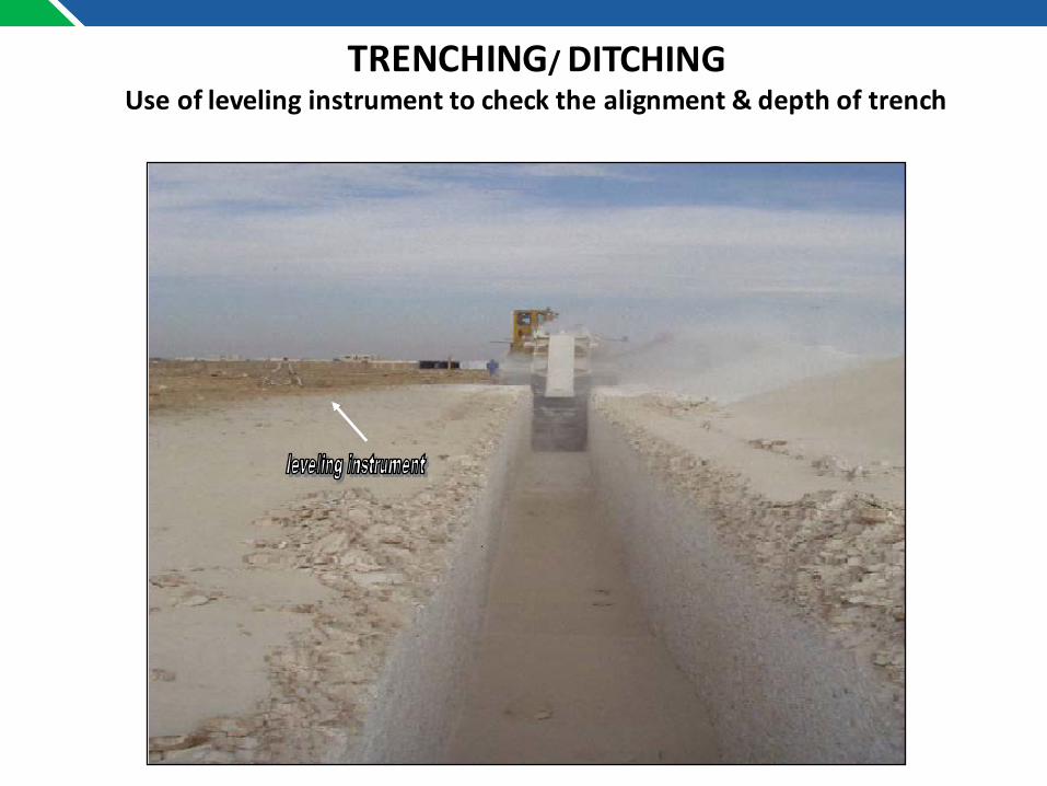
TRENCHING/DITCHINGUseoflevelinginstrumenttocheckthealignment&depthoftrench

•The trenchers are able to crush rocks to very small pieces and dig a Perfect Rectangular trench.
•Less Manpower involved as compared to Blasting and Trench Excavation by Excavators. Safer when compared to conventional method.
Water sprinkling for dust control
TRENCHING/DITCHING

2017
Stringing

Transportinganddeliveryofpipetopipeyard
STRINGING

Stringingistheplacingofpipealongthetrench.
STRINGING
Unloadingoflinepipesfromtrailerwiththehelpofvacuumlift

STRINGINGPipe is not be placed directly on the ground but on skids, with proper padding. Dragging, skidding or dropping of the pipe is not permitted. Wooden wedges are used to prevent movement of pipe.
Strung Pipes along the trench
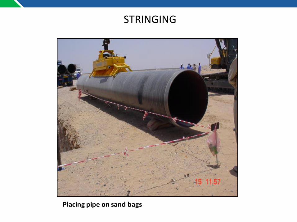
Placingpipeonsandbags
STRINGING

2017
Bending
BENDING
All necessary pipe field bends require a trigonometric survey toestablish the number and degree of bends to ensure that theinstalled pipe conforms to the contours of the pre-padded trench.
The radius of cold bends shall be not less than 40 times the pipediameter.
A smooth stretch-bending machine makes the cold bends. Bendswith ripples with a depth exceeding 0.5 mm, wrinkles and kinksare not acceptable.
The procedure for bending is such that the extremities of each joint remain straight over a minimum distance of 2 m or twice the pipe diameter, whichever is greater. Bending shall take place before any double jointing. The lay out and measure of the pipe for bending is such that the length of off-cuts is kept to a minimum.

LinepipeBending,MandrelSet-Up
Bending Machine
BENDING

PipebendinginProgress
BENDING

GaugingPlateinspectionafterbending
BENDING

2017
Welding
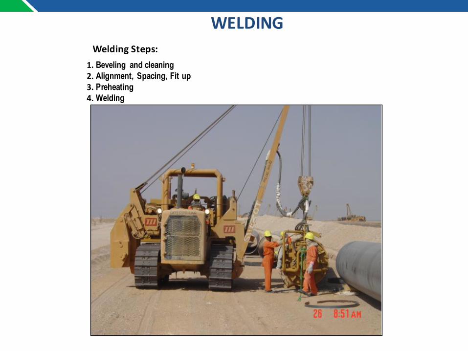
WeldingSteps:1. Beveling and cleaning2. Alignment, Spacing, Fit up 3. Preheating4. Welding
WELDING

UseofspiderBurnersforpreheating
WELDING

InternalWeldingMachine
In-Situ Beveling Machine
WELDING

WeldingHuts
WELDING

AutomaticWeldingMachine
Automatic welding Machine
WELDING

WeldingInprogress
WELDING
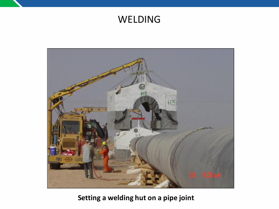
Settingaweldinghutonapipejoint
WELDING
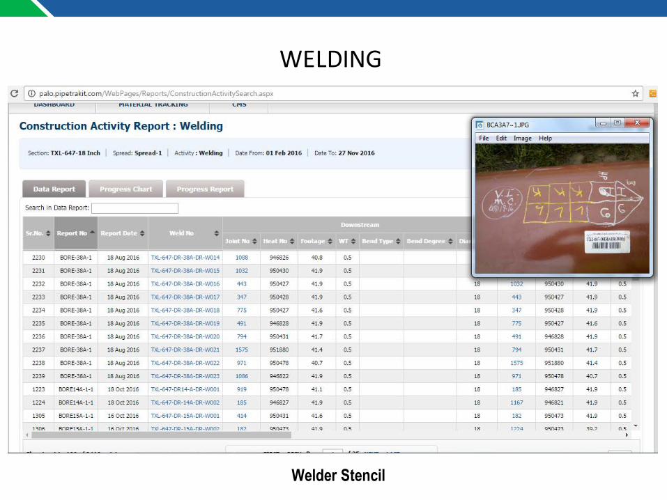
Welder Stencil
WELDING

Identification of Welds:Each weld is clearly marked with weather proof chalk or paint to denote the weld number and welder(s) making the weld. These marks are in a very specific format and order on the pipe using a combination of numeric, alphanumeric and other marks or symbols.
WELDING

PIPE weld numbering
KPNNN – (AAANN) – WNN (AA)
KP
FabricationRef.
WeldNo
RepairStatus
•KP is the KP digit format from as per requirement•Fabrication Reference is the optional part of the weld number that identifies the special weld and coded as follows;

Type Code This code indicates;
Crossing
Road Crossing
RDX1RDX2RDX3RDX4RDX5RDX6
River Crossing
RFX1RFX2RFX3RFX4
Tie In
Tie - In TI
•The tie in between KP sections or at crossing locations etc.
Final Tie - InFTI001FTI002
… •The welds that will not be subject to hydro test. (I.E locations at each end of a block valve assembly etc.)
Prefix generally used for the Identification of type of Weld

Block ValveBV01
…BV09 •All welds made on each block valve assembly and site completion
Test Ends
TE01TE02
•Temporary welds for hydro test purposes
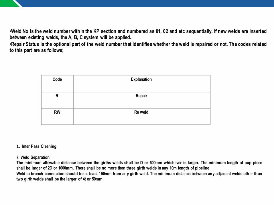
•Weld No is the weld number within the KP section and numbered as 01, 02 and etc sequentially. If new welds are insertedbetween existing welds, the A, B, C system will be applied.•Repair Status is the optional part of the weld number that identifies whether the weld is repaired or not. The codes relatedto this part are as follows;
Code Explanation
R Repair
RW Re weld
1. Inter Pass Cleaning
7. Weld SeparationThe minimum allowable distance between the girths welds shall be D or 500mm whichever is larger. The minimum length of pup pieceshall be larger of 2D or 1000mm. There shall be no more than three girth welds in any 10m length of pipelineWeld to branch connection should be at least 150mm from any girth weld. The minimum distance between any adjacent welds other thantwo girth welds shall be the larger of 4t or 50mm.

X-raybyinternalcrawler
NONDESTRUCTIVETESTING

AutomaticUltrasonicTestingMachine
NONDESTRUCTIVETESTING

AutomaticUltrasonicTestinginprogress
NONDESTRUCTIVETESTING

GritBlastinginProgress
FieldJointCoating
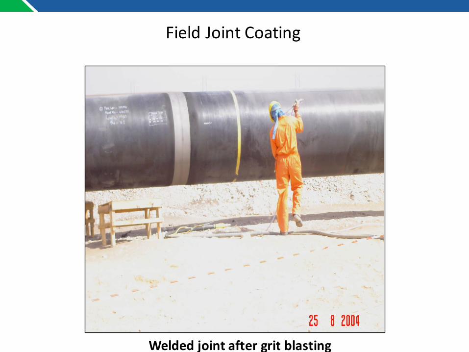
Weldedjointaftergritblasting
FieldJointCoating
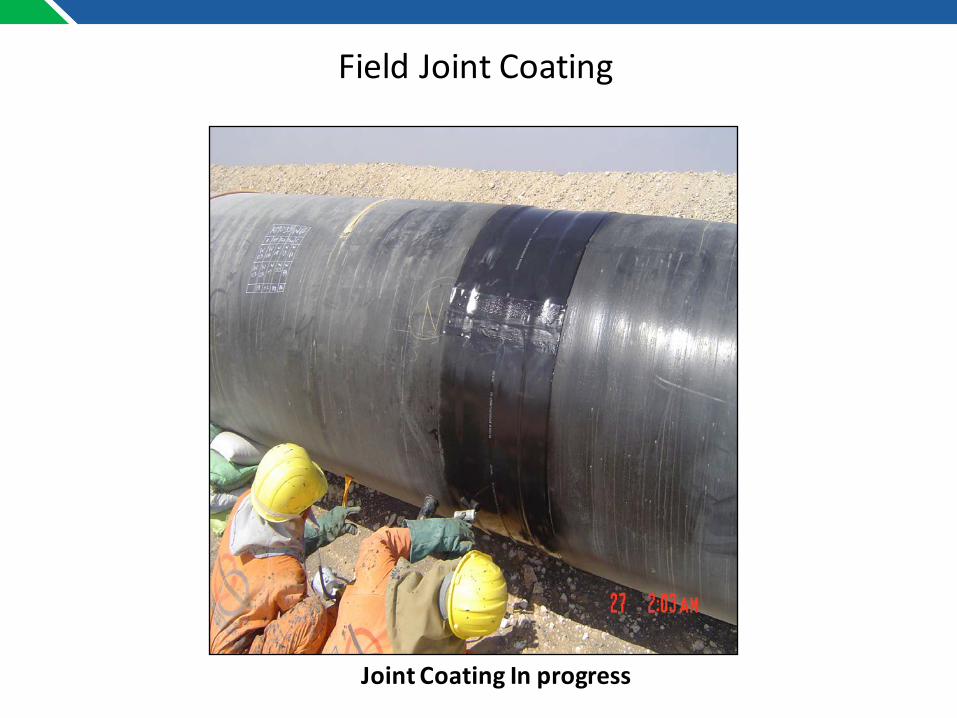
JointCoatingInprogress
FieldJointCoating
2017
PRE-PADDING

Pre-paddingoftrenchinprogress
BACK HOE
SCREENING PLANT
Pre-Padding

Spreadingofpre-paddingmaterialwiththehelpofBobcat
Pre-Padding

2017
Lowering-in
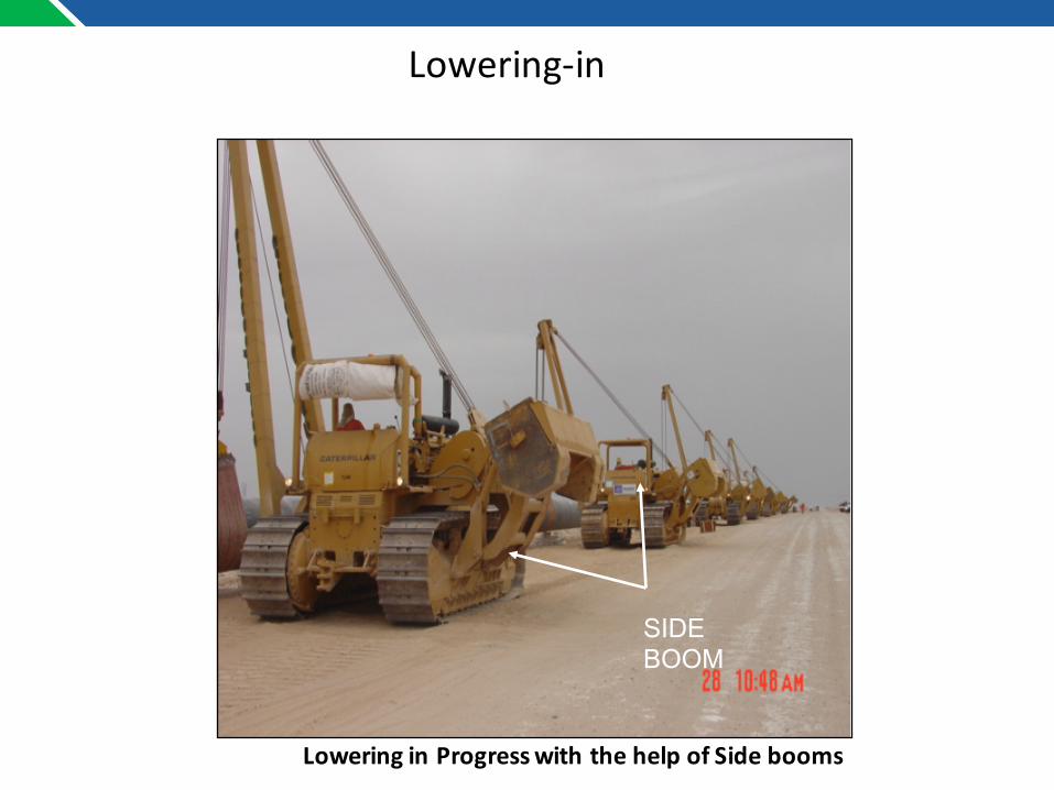
LoweringinProgresswiththehelpofSidebooms
SIDE BOOM
Lowering-in

ReadytoLowertheSectionRollingCradlesusedforSmooth&fasterOperationofLowering.
CRADLES
Lowering-in

Loweringinprogress
Lowering-in

Loweringinprogress
Lowering-in

2017
PostPadding&Backfilling
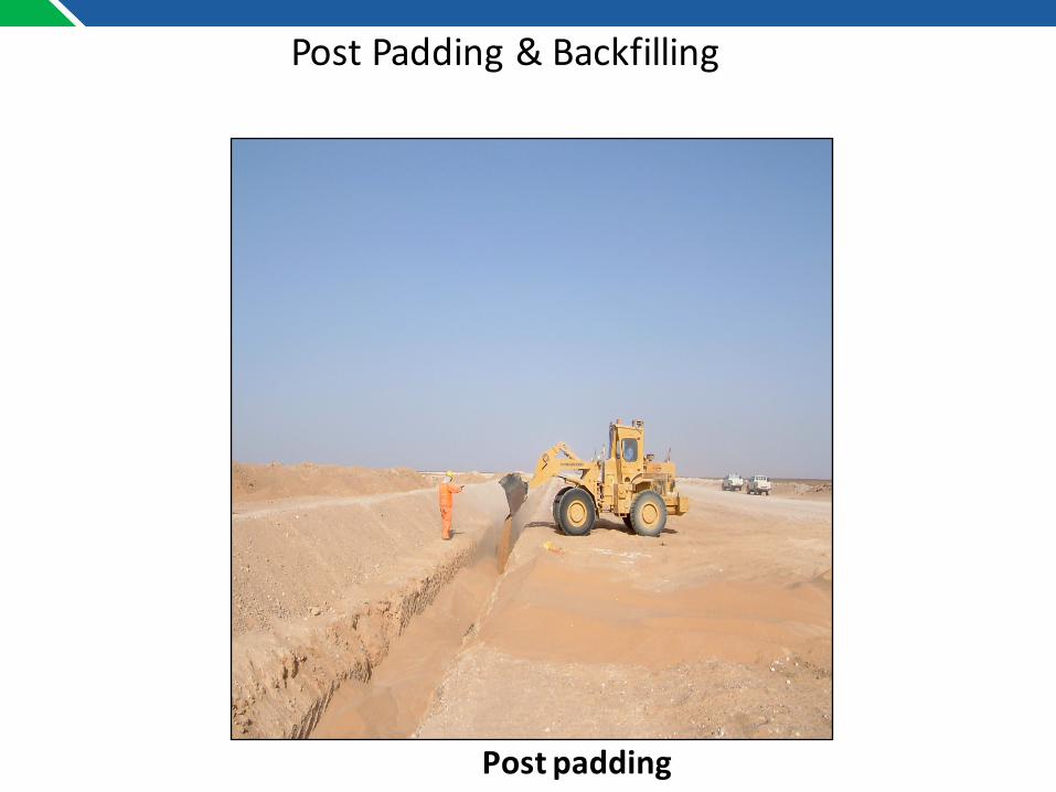
Postpadding
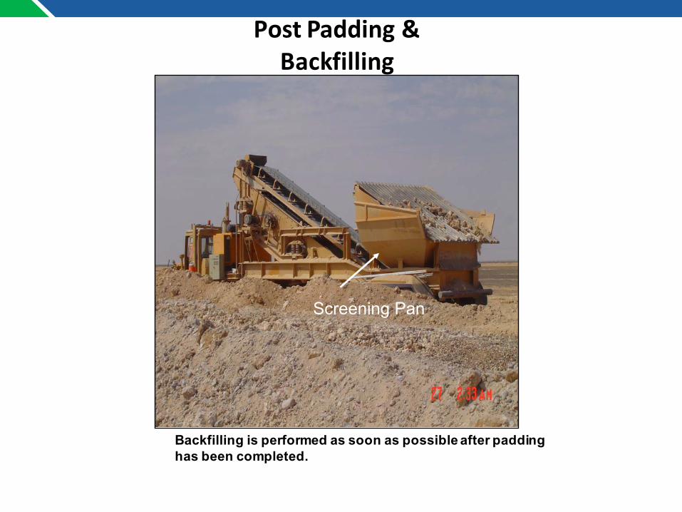
PostPadding&Backfilling
PostPadding&Backfilling
Backfilling is performed as soon as possible after padding has been completed.
Screening Pan
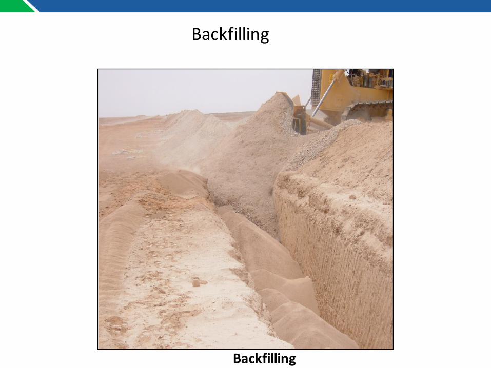
Backfilling
Backfilling
2017
HydrostaticTesting

Breaktank&filterarrangementforhydro-testing
WATER FILTER
BREAKTANK
HydrostaticTesting

TestCabinforpressureMonitoring
DEAD WEIGHT TESTER
HydrostaticTesting

Hydro-testingarrangement
HydrostaticTesting

Hydro-testingBackpressureArrangement
HydrostaticTesting

Hydro-testingHeader&Compressor
HydrostaticTesting

MagneticPIGformagneticdebriscollation
Hydrotesting– Drying&Swabbing

GaugePlateisusedtoprovepiperoundnessandensureexcessiveweldpenetrationordebrisdoesnotexistinthepipeinterior.
HydrostaticTesting– Drying&Swabbing
2017
BlockValveInstallation

Blockvalvestation
BlockValveInstallation
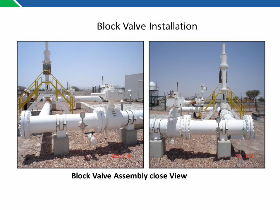
BlockValveAssemblycloseView
BlockValveInstallation
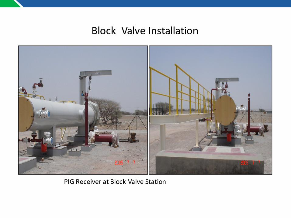
PIGReceiveratBlockValveStation
BlockValveInstallation

2017
FinalGrading&FullRestoration

2017