pipe - wl plastics 0117 field procedures.pdf · joining wl plastics pipe and other manufacturer’s...
TRANSCRIPT

WL101-0117 Rev Jan 2017 Supersedes all previous editions © 2017 WL Plastics Corp.
WL101
Joining & Field Procedures
For
WL Plastics
PE4710
PE3608
PE3408
PE2708
PE2406
Pipe
2 Joining & Field Procedures for Pipe
WL101-0117 Rev Jan 2017 Supersedes all previous editions © 2017 WL Plastics Corp.
NOTICE
This publication is intended for use as a guide for piping systems. It should not be used in place of a professional engineer’s judgment or advice and it is not intended as installation instructions. WL Plastics Corporation has made every reasonable effort to ensure accuracy, but the information in this publication may not be complete, especially for special or unusual applications. The information in this publication cannot be guaranteed because the conditions of use are beyond our control and the information in this publication does not constitute a guarantee or warranty for piping installations. The user of this information assumes all risk associated with its use. Changes to this publication may occur from time to time without notice. Contact WL Plastics Corporation to determine if you have the most current edition. Copying without change permitted.
Table of Contents
Pipe Unloading and Handling.................................................................................................................................................. 4
Unloading ............................................................................................................................................................................. 4
Jobsite Pipe Storage, Unpacking, and Handling ................................................................................................................. 4
Pipe Weight ......................................................................................................................................................................... 4
Subfreezing and Inclement Weather Conditions ................................................................................................................. 4
Field Bending ....................................................................................................................................................................... 5
Field Cutting......................................................................................................................................................................... 5
Hazardous Environments ........................................................................................................................................................ 5
Static Electric Discharge ...................................................................................................................................................... 6
Underground Excavation ..................................................................................................................................................... 6
Confined Spaces ................................................................................................................................................................. 6
Fusion and Joining and Compatibility ..................................................................................................................................... 6
Fusion Training and Proficiency .......................................................................................................................................... 6
Joining WL Plastics Pipe and Other Manufacturer’s Products ............................................................................................ 6
Liquid Hydrocarbon Permeated Pipe .................................................................................................................................. 7
Butt Fusion .............................................................................................................................................................................. 7
General Considerations ....................................................................................................................................................... 7
Butt Fusion Joining Restrictions .......................................................................................................................................... 7
OD Compatibility .............................................................................................................................................................. 7
Wall Thickness (DR) Compatibility .................................................................................................................................. 8
Fusion Quality Verification – Data Logging and Testing ..................................................................................................... 8
Fusion Evaluation Tests – NDE (Non-Destructive Evaluation) ........................................................................................... 9
Fusion Evaluation Tests – Mechanical Field and Laboratory Tests .................................................................................... 9
Weather Guidelines ........................................................................................................................................................... 10
Wind Effects ................................................................................................................................................................... 10
Precipitation and Airborne Contaminants ...................................................................................................................... 10
Temperature Effects ...................................................................................................................................................... 10
Butt Fusion Set-Up ............................................................................................................................................................ 11
Heating Temperature and Interfacial Pressure .............................................................................................................. 11
Butt Fusion Procedure ....................................................................................................................................................... 11
Step 1 – Clean and then secure the Components in the Butt Fusion Equipment ......................................................... 12

Joining & Field Procedures for Pipe 3
WL101-0117 Rev Jan 2017 Supersedes all previous editions © 2017 WL Plastics Corp.
Step 2 – Face the Component Ends .............................................................................................................................. 12
Step 3 – Align the Faced Component Ends................................................................................................................... 12
Step 4 – Melt the Component Ends ............................................................................................................................... 13
Step 5 – Remove Heating Tool, Inspect Melt, Join, Apply and Hold Fusion Joining Force .......................................... 14
Step 6 – Visually Inspect Fusion Bead and Joint Appearance ...................................................................................... 15
Approximate Butt Fusion Joining Rates ............................................................................................................................ 16
Bead Removal ................................................................................................................................................................... 16
Saddle (sidewall) Fusion, Socket Fusion and Electrofusion ................................................................................................. 16
Extrusion and Hot-Air (Hot-Gas) Welding ............................................................................................................................. 17
Tapered Pipe Threads .......................................................................................................................................................... 17
Mechanical Connections ....................................................................................................................................................... 17
Joint Restraint and Thrust Blocks ...................................................................................................................................... 17
Pressure Testing ................................................................................................................................................................... 18
Hydrostatic Pressure Leak Testing.................................................................................................................................... 18
Pneumatic Pressure Leak Testing..................................................................................................................................... 19
Field Pressure Rating Tests .............................................................................................................................................. 19
Installation ............................................................................................................................................................................. 19
Repair .................................................................................................................................................................................... 19
Operating Procedures ........................................................................................................................................................... 20
Disinfecting Potable Water Piping ..................................................................................................................................... 20
Squeeze-Off....................................................................................................................................................................... 20
Cleaning ............................................................................................................................................................................. 20
References ............................................................................................................................................................................ 21

4 Joining & Field Procedures for Pipe
WL101-0117 Rev Jan 2017 Supersedes all previous editions © 2017 WL Plastics Corp.
PIPE UNLOADING AND HANDLING
Unloading
Before unloading WL Plastics pipe from the truck, unloading personnel should obtain WL111 WL Plastics Unloading Guidelines from the driver and read the WL Plastics Unloading Guidelines. The truck driver receives WL111 WL Plastics Unloading Guidelines when accepting the load at the manufacturing plant, and is instructed to give WL111 WL Plastics Unloading Guidelines to unloading personnel at the unloading site. WL111 WL Plastics Unloading Guidelines are also available from the WL Plastics website, www.wlplastics.com or by contacting WL Plastics.
Observe WL111 WL Plastics Unloading Guidelines whenever unloading WL Plastics pipe products. Improper unloading can result in death, injury, property damage or product damage.
Jobsite Pipe Storage, Unpacking, and Handling
The jobsite pipe storage area should be relatively level and smooth, and large enough for the safe movement of pipe and handling equipment. In general, pipe should be stored as packaged until it is needed for installation.
On level ground, do not stack bulk packs higher than they were stacked on the truck. On less level ground, bulk packs should not be stacked, but should be stored individually on the ground.
Bulk packs must be on the ground before banding is removed.
Coiled pipe should be stored as packaged on relatively level, smooth ground. Do not stack coils higher than the original packaging. Individual coils are lifted with appropriate lifting equipment, which is typically by extending padded forklift forks into the center of the coil, or by lifting the coil with fabric slings – not chain or wire rope – looped through the center of the coil. Forks can be padded by installing fork-length sections of plastic pipe over the forks.
Coils that are packaged on pallets should be removed one by one from the top down. Remove only enough banding to release the upper coil, and then slide the coil over onto forklift forks. Forks must be long enough for the full coil diameter, and set apart as wide as practical. Do not push coils off the silo onto the ground.
Take safety measures to protect persons against injury before banding on individual coils is removed, – coiled pipe will spring out suddenly with force when restraining bands are removed. Safety measures can include placing the coil in equipment that confines (cages) the coil, cutting bands from inside of the coil, or other safety measures. When coils are placed in confining equipment, never place any part of the body – hands, arms, feet legs, head – between the coil and the confining equipment.
Keep persons that are not involved in handling WL Plastics piping products away from handling operations.
When piping products and handling equipment are in motion, all persons involved in handling WL Plastics piping products should be able to see all other persons at all times. If any handling person is not in sight, immediately stop moving equipment and products and locate that person. Do not continue until all persons are accounted for and in sight.
Use only appropriate lifting and handling equipment that is in safe operating condition, that is properly rated for the load, and that is designed for the intended use.
Do not lift or move WL Plastics products with equipment such as wire rope or chain that can damage the pipe. Equipment that contacts the pipe should be fabric slings or should be rounded or padded to prevent damage to the pipe.
Uncontrolled movement of products or equipment can be hazardous. Never push, roll, dump or drop pipe lengths, bundles or coils off the truck, off handling equipment or into a trench. Always use appropriate equipment to lift, move and lower the pipe.
Pipe Weight
Polyethylene pipe is lightweight compared to other piping products, but larger pipe sizes, longer lengths, and large coils of pipe can be heavy. Weight information for WL Plastics polyethylene piping products is available in WL102A and WL102B for IPS sized pipe, WL104 for DIPS sized pipe, WL130 for FM Approved pipe, and WL108 for standard packaging and truckload quantities for coiled pipe and pipe joints.
Subfreezing and Inclement Weather Conditions
In subfreezing conditions, thermoplastics such as polyethylene become more vulnerable to damage from suddenly applied impact, and become more resistant to bending and uncoiling. Polyethylene pipe is ductile to temperatures well below -50°F (-46°C), and retains significant toughness in sub-freezing conditions. However, all materials including polyethylene become less flexible and more sensitive to cutting and impact in freezing and sub-freezing conditions. In very cold conditions, PE

Joining & Field Procedures for Pipe 5
WL101-0117 Rev Jan 2017 Supersedes all previous editions © 2017 WL Plastics Corp.
pipe will be harder to straighten or bend. When pulling through straightening and rerounding equipment Pull-through speed must be slowed by half or more in cold weather conditions.
When cutting PE pipe with a saw, bending the pipe to open the cut can cause the pipe to fracture through before the cut is complete. PE pipe should be properly handled and placed where it needs to be. In very cold conditions, dropping the pipe can result in pipe fracture, especially on uneven or rocky terrain. Dropped pipe frequently hits one end first end and then the other end slaps down, multiplying or even repeating the impact. Do not drop the pipe or push it off a trailer such that it drops onto the ground or into the trench.
In subfreezing temperatures, suddenly applied impact from dropping the pipe, striking it forcefully, dropping heavy items on the pipe, or sudden extreme surge pressure can break the pipe. When force is applied to bend or uncoil pipe, springback from unintended sudden release can be forceful.
Water can freeze solid in the pipe without damaging the pipe. Ice expands as it forms causing the pipe to expand. Ductile pipe expansion from ice formation does not damage the pipe.
Frozen pipes should be thawed by warming the pipe. Warming temperature should not exceed 120°F. WL Plastics polyethylene pipes can be heat traced provided heat tracing temperature is limited to 120°F.
Do not try to clear an ice plug by increasing pressure, which can cause an ice plug to move rapidly down the line where a sudden stop at an obstruction such as a fitting or an appurtenance can cause severe water hammer that can burst and fragment the pipe. Flying fragments can cause injury or property damage.
HDPE contracts when cold. Pipe diameter and length are reduced in lower temperatures. (Pipe dimensions and specifications are for pipe at 73°F (23°C), and will vary for pipe at higher or lower temperature.)
Caution – Do not climb or walk on pipe. Pipe can be slippery whether dry or wet or snow-covered.
Field Bending
HDPE pipe is flexible and may be bent in the field to sweep the pipe around to follow trench curves or terrain contours. In general, field bending to roughly 75 times the pipe diameter can be accomplished with relative ease. Tighter bends down to the minimum acceptable field bending radius and colder temperatures require greater effort. Tighter field sweep bends generally require embedment support. For field bending radius information, see WL113 and the PPI Calculator (http://plasticpipe.org/publications/software-ppi-calculator.html).
Care and safety precautions are required to maintain control over the pipe during field bending installation to prevent springback until the pipe is secured in its final field-bend configuration.
Field Cutting
WL Plastics Polyethylene pipe may be cut using various hand operated and powered hand operated cutting tools. Smaller pipes may be cut with plastic pipe cutters or hand saws. Hand operated pipe cutters for 2” and smaller pipes typically drive a guillotine knife blade through the pipe with a ratcheting mechanism. Coarse tooth saws provide chip clearance and may be used for any size. Fine tooth saw blades can load up with cuttings. Powered hand tools such as reciprocating saws and chain saws may also be used. Do not use bar chain lubrication if cutting pipe with a chainsaw. Bar chain lubrication contaminates the pipe surface. Contamination must be removed. If not removed, contamination can reduce joint quality or transfer to fusion equipment, and reduce the quality of subsequent joints.
Hand operated, powered abrasive wheel cutting tools are not recommended because abrasive wheels load up with melted PE material and are susceptible to kickback. Hand operated, powered circular saws are not recommended because PE pipes can bind against the blade and circular saws are susceptible to kickback.
Holes for perforations or branch outlets may be cut using standard wood or metal cutting drill bits or circular hole saws and hand operated or powered hand operated drilling tools. Spade type wood cutting bits do not work well with polyethylene. Circular hole saws for cutting polyethylene pipe have few teeth, high chip clearance, and are available from fusion equipment suppliers.
All hand operated and powered hand operated tools should be operated in accordance with manufacturer’s instructions, including all applicable personal protective equipment.
HAZARDOUS ENVIRONMENTS HDPE piping is sometimes installed or operated in environments that can be hazardous. Take safety precautions to protect against death, injury, property damage and pipe damage.

6 Joining & Field Procedures for Pipe
WL101-0117 Rev Jan 2017 Supersedes all previous editions © 2017 WL Plastics Corp.
Static Electric Discharge
HDPE pipe does not conduct electricity. In dry, low humidity conditions, static electric charges can develop on the surface of exposed HDPE pipe. Avoid working with or operating exposed HDPE pipe in a flammable gas or explosive dust environment, but if working with or operating in a flammable gas or explosive dust environment cannot be avoided, take measures to dissipate static electric charges on the pipe surface. In a flammable gas or explosive dust environment, a static electric discharge can cause explosion or fire. Static electricity dissipation measures generally involve wetting exposed pipe to a grounded (buried) location with a conductive fluid, wrapping the wetted pipe surface with a fabric (such as burlap) or conductive film, and periodic rewetting to maintain surface conductivity to ground.
Equipment and tools that may contact static charged pipe should be grounded. Observe safety policies, procedures and regulatory requirements for personal protective equipment and clothing in accordance with installing or operating company policies and regulations.
Electrical equipment such as fusion tools are not usually explosion proof. Do not operate fusion tools or electrical equipment that is not explosion proof in a flammable gas or explosive dust environment. In a flammable gas or explosive dust environment, a spark from electrical equipment can cause explosion or fire.
Underground Excavation
In unstable soils, trench walls can collapse and endanger persons in the trench. Consult the appropriate regulatory authority and observe all safety requirements when excavating or working in a trench. Protective equipment and devices such as sheeting, shoring and trench boxes can be necessary.
Confined Spaces
Some HDPE piping applications such as rehabilitation or sliplining can require work in confined spaces such as manholes. Safety measures such as personal respiratory equipment, personal lowering and lifting equipment, equipment to test for safe downhole atmospheric conditions, personal protective equipment and clothing, safety personnel stationed at the top of the shaft, and other measures can be required. Observe all requirements for confined spaces personal protection and safety specified by installing or operating companies and regulatory authorities.
FUSION AND JOINING AND COMPATIBILITY
Fusion Training and Proficiency
Field fusion joints should be made by trained, experienced persons that can demonstrate that they can produce sound joints using the joining procedure and joining equipment. Proficiency is demonstrated by (1) providing written proof that within 12-months, the person received training in the fusion procedure and equipment that is appropriate for the pipe size being joined, and that joints made during training were tested and found to be acceptable, or (2) that the person has made appropriate size fusion joints within 12 months and that not more than 3 unacceptable joints were produced during that period. Proficiency tests typically include visual inspection and destructive mechanical tests such as bent strap tests or tensile tests. Visual inspection guidelines for butt fusions are presented in the butt fusion procedures.
Joining WL Plastics Pipe and Other Manufacturer’s Products
Fusion uses controlled heating to melt prepared piping component surfaces, and then joins the melted surfaces under controlled pressure, which causes the melted surfaces to mix and fuse together. Properly made fusion joints will meet or exceed the tensile and pressure requirements for the pipe, and do not leak. Fusion procedures are qualified by making and testing joints to prove short-term and long-term performance.
Correctly made fusion joints do not leak. Leakage at a pressure pipe fusion joint can indicate a faulty joint that can separate suddenly. If leakage is observed in a pressure pipe fusion joint, move away immediately and depressurize the line. Do not reapply pressure until the faulty joint has been replaced.
Fusion requires specialized equipment for the particular procedure. Persons making fusion joints should be trained and experienced in the qualified joining procedure and in equipment setup, operation and maintenance.
WL Plastics polyethylene piping products are heat fusion joined to themselves or to other products using the qualified butt fusion and saddle fusion procedures in this publication. WL Plastics polyethylene pipes are made from polyethylene compounds having material designations that include PE4710, PE3608, PE3408, PE2708 and PE2406. Some higher material designations will meet or exceed lesser material designations, and where a pipe manufacturing standard may not incorporate the higher material designation, higher and lesser material designations may be marked on the pipe. The qualified heat fusion procedures in this publication are used to join WL Plastics pipes made from any polyethylene compound material designation to WL Plastics pipe having the same material designation or to WL Plastics pipe having any other or multiple material designations.
Joining & Field Procedures for Pipe 7
WL101-0117 Rev Jan 2017 Supersedes all previous editions © 2017 WL Plastics Corp.
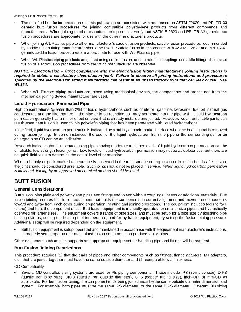
The qualified butt fusion procedures in this publication are consistent with and based on ASTM F2620 and PPI TR-33 generic butt fusion procedures for joining compatible polyethylene products from different compounds and manufacturers. When joining to other manufacturer’s products, verify that ASTM F 2620 and PPI TR-33 generic butt fusion procedures are appropriate for use with the other manufacturer’s products.
When joining WL Plastics pipe to other manufacturer’s saddle fusion products, saddle fusion procedures recommended by saddle fusion fitting manufacturer should be used. Saddle fusion in accordance with ASTM F 2620 and PPI TR-41 generic saddle fusion procedures are appropriate for use with WL Plastics pipe.
When WL Plastics piping products are joined using socket fusion, or electrofusion couplings or saddle fittings, the socket fusion or electrofusion procedures from the fitting manufacturer are observed.
NOTICE – Electrofusion – Strict compliance with the electrofusion fitting manufacturer’s joining instructions is required to obtain a satisfactory electrofusion joint. Failure to observe all joining instructions and procedures specified by the electrofusion fitting manufacturer can result in an unsatisfactory joint that can leak or fail. See WL124.
When WL Plastics piping products are joined using mechanical devices, the components and procedures from the mechanical joining device manufacturer are used.
Liquid Hydrocarbon Permeated Pipe
High concentrations (greater than 2%) of liquid hydrocarbons such as crude oil, gasoline, kerosene, fuel oil, natural gas condensates and the like that are in the pipe or in surrounding soil may permeate into the pipe wall. Liquid hydrocarbon permeation generally has a minor effect on pipe that is already installed and joined. However, weak, unreliable joints can result when heat fusion is used to join polyolefin piping that has been permeated with liquid hydrocarbons.
In the field, liquid hydrocarbon permeation is indicated by a bubbly or pock-marked surface when the heating tool is removed during fusion joining. In some instances, the odor of the liquid hydrocarbon from the pipe or the surrounding soil or an enlarged pipe OD can be an indication.
Research indicates that joints made using pipes having moderate to higher levels of liquid hydrocarbon permeation can be unreliable, low-strength fusion joints. Low levels of liquid hydrocarbon permeation may not be as deleterious, but there are no quick field tests to determine the actual level of permeation.
When a bubbly or pock-marked appearance is observed in the melt surface during fusion or in fusion beads after fusion, the joint should be considered unreliable. Such joints should not be placed in service. When liquid hydrocarbon permeation is indicated, joining by an approved mechanical method should be used.
BUTT FUSION
General Considerations
Butt fusion joins plain end polyethylene pipes and fittings end to end without couplings, inserts or additional materials. Butt fusion joining requires butt fusion equipment that holds the components in correct alignment and moves the components toward and away from each other during preparation, heating and joining operations. The equipment includes tools to face (plane) and heat the component ends. Butt fusion equipment is manually operated for smaller size pipes and hydraulically operated for larger sizes. The equipment covers a range of pipe sizes, and must be setup for a pipe size by adjusting pipe holding clamps, setting the heating tool temperature, and for hydraulic equipment, by setting the fusion joining pressure. Additional setup will be required depending on the equipment.
Butt fusion equipment is setup, operated and maintained in accordance with the equipment manufacturer’s instructions. Improperly setup, operated or maintained fusion equipment can produce faulty joints.
Other equipment such as pipe supports and appropriate equipment for handling pipe and fittings will be required.
Butt Fusion Joining Restrictions
This procedure requires (1) that the ends of pipes and other components such as fittings, flange adapters, MJ adapters, etc., that are joined together must have the same outside diameter and (2) comparable wall thickness.
OD Compatibility
Several OD controlled sizing systems are used for PE piping components. These include IPS (iron pipe size), DIPS (ductile iron pipe size), DIOD (ductile iron outside diameter), CTS (copper tubing size), inch-OD, or mm-OD as applicable. For butt fusion joining, the component ends being joined must be the same outside diameter dimension and system. For example, both pipes must be the same IPS diameter, or the same DIPS diameter. Different OD sizing

8 Joining & Field Procedures for Pipe
WL101-0117 Rev Jan 2017 Supersedes all previous editions © 2017 WL Plastics Corp.
systems are not compatible, e.g., IPS and DIPS cannot be butt fused to each other. ID controlled (SIDR) pipes are joined using insert type mechanical fittings and are not suitable for butt fusion joining. See WL116 for applicable PE pipe standards.
Wall Thickness (DR) Compatibility
The DR of the lower DR component end must not be less than 0.79 times the DR of higher DR component end. To determine if components with different DR’s can be joined together, multiply the higher DR by 0.79. If the lower DR is this number or higher, the components can be joined together using this procedure.
EXAMPLE – What is the lowest DR to which DR 19 can be joined?
DR 19 x 0.79 = DR 15; therefore, joining is acceptable pipe to pipe, or pipe to fitting where the ends to be joined are DR 15 through DR 19.
If the DR difference is too great, joining should be by transition nipple, mechanical coupling, electrofusion coupling, or flanges. A transition nipple is a short section of pipe where one end is the lower DR and the other end is bored to the higher DR.
Fusion Quality Verification – Data Logging and Testing
Hydraulic butt fusion machines should be equipped with data logging technology to monitor and record time, temperature and pressure during fusion. Field fusion data logger records that compare favorably with destructively-tested trial fusion data logger records can provide confidence in field fusion quality.
Fusion quality may be evaluated by preparing a trial fusion and performing destructive tests. These tests can be performed either onsite in the field, or in laboratory settings. For field testing there are two options, first ASTM F2620 bent strap test can be used on pipes with a wall thickness less than 1”, or ASTM F3183 guided side bend test can be performed on pipes with a wall thickness greater than 1”. These are both approved fusion evaluations that can be performed onsite in the field. For laboratory evaluation both ASTM D638 tensile test, and ASTM F2634 tensile impact test of specimens cut from the fusion are allowed. Prior to testing, test samples must be conditioned completely to 73°F/23°C.
ASTM F2620 includes a bent strap test for pipes having a wall thickness of 1-in (25 mm) or less. Butt fusions may be evaluated by cutting straps from a trial fusion and conducting an ASTM F2620 strap bend test. See Figure 1. The cut through the fusion should be visually examined. Voids or disbonded areas at the fusion plane are not acceptable. Strap specimens are then bent once with the pipe OD or ID to the inside of the bend so that the ends of the strap touch. Disbondment at the fusion zone is unacceptable.
Figure 1 Butt Fusion Strap Bend Test Specimen for 1-in (25 mm) or thinner pipe wall, t
ASTM F3183 guided side bent test is a three point side bend performed on a transverse sample cut from a butt fusion joint. See Figure 2. This field test is performed on pipe with a wall thickness of 1-in (25mm) or greater. WL Plastics recommends using a loading nose radius “R” to specimen thickness “T” ratio “R/T” of 2.0 or greater to test the specimens at a maximum of 20% strain. The bend angle shall not exceed 90°. These values can be found in ASTM F3183 in Table X3.1. Most three point side bend testing machines purchased or rented come with a 1-in diameter loading nose. That requires a specimen thickness of 0.25” to achieve a 2.0 R/T ratio. Depending on the type of planer used, it may be difficult to achieve a uniform thickness of 0.25” across the entire specimen when preparing them in the field. If that is the case, WL Plastics suggests using a 0.50” specimen thickness which will require a 2-in diameter loading nose to maintain the proper 2.0 R/T ratio. Test specimens must be conditioned completely to 73°F/23°C before test is conducted. Breakage or tearing at the fusion zone is unacceptable.

Joining & Field Procedures for Pipe 9
WL101-0117 Rev Jan 2017 Supersedes all previous editions © 2017 WL Plastics Corp.
Figure 2 Side Bend Specimen
ASTM D638 tensile tests may be conducted on ASTM D638 tensile bar specimens (Type III or IV are preferred) machined from samples cut longitudinally from each quadrant of a trial fusion with the fusion in the center of the tensile bar specimen reduced area. See Figure 3. The sides of the tensile bar specimen reduced area must be smooth and free from nicks, cuts and surface irregularities, and any machining marks that are not parallel to the direction of pull. Sanding with very fine (00) sandpaper using strokes parallel to the direction of pull may be required. If wall thickness is reduced, the tensile specimen fused area should be from the middle of the pipe wall. After specimen preparation, condition test specimens by immersion in temperature controlled circulating air for not less than 4 hours or in temperature controlled circulating water for not less than 1 hour. Test at 73°F (23°C) and 50 mm/min (2-in/min) separation rate. Specimens should demonstrate ductility by yielding and visibly necking down. ASTM F2634 is a tensile impact test of specimens taken from butt fusions.
Figure 3 Butt Fusion Tensile Specimen
Fusion Evaluation Tests – NDE (Non-Destructive Evaluation)
As of this writing, various non-proprietary NDE (non-destructive evaluation) methods such as ultrasonic and X-ray, and proprietary NDE methods such as time of flight diffraction (TOFD), phased array (PA), and microwave (evisive) claim the ability to inspect for fusion joint quality. However, although various NDE techniques have been researched for over 40 years none have proved to be reliable indicators of HDPE fusion joint quality. Research continues, but at this time WL Plastics does not recommend these unproven NDE methods as indicators of fusion quality because independent, peer reviewed proof of reliability does not exist. The only reliable NDE inspection technique to date is visual butt fusion bead examination.
Fusion Evaluation Tests – Mechanical Field and Laboratory Tests
ASTM standardized tests are recommended for evaluating fusion joint quality. Published ASTM testing procedures are peer-developed and confirmed to produce reliable, repeatable results. Tests and techniques for other materials or that are under development are unproven and experimental and may be too stringent or ineffective and are not reliable indicators of fusion quality. Tests published by an ANSI-certified standards development organization such as ASTM are recommended.
Tests for metal welds such as bending a strap or coupon in a bench vise, bending back and forth multiple times, or hammering on bent or unbent specimens are not reliable indicators of butt fusion quality.
Although commercial equipment is available, field tensile tests are unproven, experimental technology and are not reliable fusion joint quality indicators.
NOTICE – The use of unproven, experimental fusion testing equipment and techniques is at the sole and exclusive risk and responsibility of the user.

10 Joining & Field Procedures for Pipe
WL101-0117 Rev Jan 2017 Supersedes all previous editions © 2017 WL Plastics Corp.
Weather Guidelines
Butt fusion can be successfully performed over a broad range of field conditions. However, some weather, wind and temperature conditions can affect equipment operation or performance, or can introduce contaminants that can compromise joint quality. Joining procedures may need to be adjusted to compensate for wind, weather or temperature. PE pipe and fittings will expand and contract with changes in temperature. If butt fusion machine pipe clamp closure is limited, shims of elastomeric material may be necessary to secure very cold pipe against slippage. In four-clamp machines, shims should be used only in the outer clamps.
Wind Effects
The Beaufort Wind Intensity Scale may be used to determine the effect of wind intensity on fusing operations.
A wind break or shelter should be used when jobsite wind intensity exceeds “gentle breeze” conditions.
Wind intensity above “strong breeze” may require suspending fusing operations.
Figure 4 Beaufort Wind Intensity Scale
Exposing the fusion heater plate or parts of it to higher wind intensity can cause temperature variations across the heater plate surface and non-uniform pipe end heating. Higher wind intensity can prematurely cool melted pipe ends that are exposed during heater plate removal, or can blow contaminants such as dust, dirt, and debris onto the melted pipe ends. Uneven heating, premature cooling and contamination can compromise fusion joint quality. Shelters or side curtains may be required on windy days, even warm windy days, to guard against wind chill effects.
Wind can blow into exposed pipe ends, travel through the pipe bore and cool heater surfaces and pipe end melt, or deposit contamination at the joint. To prevent air flow through the pipe bore, open pipe ends may require plugs or covers.
Precipitation and Airborne Contaminants
Fusion joining operations must be protected against precipitation such as rain, snow, sleet, hail, and against airborne contamination such as blowing dust, dirt, sand and debris. An overhead canopy may be sufficient in light precipitation. A fully enclosed shelter is appropriate when precipitation is heavier. Airborne contamination generally occurs in moderate wind intensity conditions. Fusion operations should be suspended if precipitation, wind driven precipitation or airborne contamination cannot be kept away from fusion operations.
Temperature Effects
Temperatures around 90°F (32°C) and above – A shade canopy above fusing operations is recommended to prevent excessive sunlight heating. Gloves are recommended for equipment and pipe handling.
Temperatures from about 55°F to 90°F (13°C to 32°C) – No special precautions for temperature are necessary. If

Joining & Field Procedures for Pipe 11
WL101-0117 Rev Jan 2017 Supersedes all previous editions © 2017 WL Plastics Corp.
conditions are sunny, black pipe can be much hotter than ambient temperatures. Gloves are recommended for pipe handling.
Temperatures from about 32°F to 55°F (0°C to 13°C) – In colder conditions, the initial melt bead will take longer to develop completely around the pipe ends because the pipe is at a lower temperature.
NEVER INCREASE PRESSURE DURING HEATING TO COMPENSATE FOR COLDER PIPE TEMPERATURE. Allow additional time for the initial melt bead to develop.
In colder conditions, it will take longer for the melt bead to expand to the correct size because the pipe is at a lower temperature. The heating plate surface temperature must be within the specified range of 400 to 450°F (204 to 232°C) regardless of ambient temperature or pipe temperature.
NEVER INCREASE HEATING PLATE SURFACE TEMPERATURE FOR COLD PIPE CONDITIONS.
Temperatures around 32°F (0°C) and lower – Low temperature hydraulic fluids or motor oils may be required, and equipment may need to be warmed up before use. Gasoline or diesel powered portable generators must be operated outside of any protective enclosure. In freezing or near freezing conditions, fusing operations should be conducted within a full enclosure shelter. For sub-freezing conditions (around -4°F (-20°C) and below), a full enclosure shelter with auxiliary heating should be provided. Pipe ends should be warmed using a heating blanket or warm air devices to raise the pipe temperature. Warming devices should not exceed 120°F (49°C). Heating blankets should be wrapped completely around the pipe end for even heating. Warm air heating devices should be positioned to evenly heat the full circumference of the pipe end. An alternate method of pipe warming is to clamp the pipe ends in the butt fusion machine, install the heating plate, position the pipe ends within ¼ to ½ inch (6 to 12 mm) of the heater plate face, and allow the pipe ends to warm for ½ to 1 ½ minutes. Larger diameter and greater wall thickness should receive longer warming time.
Warming PE pipe by direct open flame is prohibited due to the lack of adequate heating control, the likelihood of oxidative damage to the pipe ends, and possible pipe ignition.
Butt Fusion Set-Up
Heating Temperature and Interfacial Pressure
Heating tool surface temperature – 400-450°F (204-232°C)
The heating tool surface temperature is the temperature of surfaces that actually contact the component ends. All heating tool surface contact areas should be within the specified 400-450°F (204-232°C) temperature range. Heating tool surface temperature is verified with a pyrometer or an infrared temperature gauge (regular pyrometer and gauge calibration is recommended). Heating tools usually have a thermometer that reads internal temperature that is normally higher than surface temperature. Monitor the thermometer to assure that heating tool temperature remains constant during operation. A deviation in the thermometer reading can indicate faulty heating tool operation or loss of power.
The heating tool surfaces that contact piping component ends have a non-stick coating or covering. The non-stick coating or covering must be clean and in good condition for proper fusion. Contamination such as plastic residue from previous fusions can be removed with wood sticks or clean, untreated, dry, lint-free non-synthetic cloths. Never use metal or abrasive implements to clean heating tool surfaces because these implements will damage the non-stick coating or covering. Burned or charred material should be removed in accordance with the equipment manufacturer’s instructions. Never apply chemicals to heating tool surfaces. Some chemicals can be absorbed into the non-stick surface and can transfer to the pipe ends during fusion and contaminate the joint.
Hydraulic fusion machine interfacial pressure – 60-90 psi (4.1-6.2 bar)
The interfacial pressure is used to calculate hydraulic fusion equipment settings; it is not the fusion joining machine setting. For hydraulically operated butt fusion machines, a joining force pressure setting is determined using a 60-90 psi (4.1-6.2 bar) interfacial pressure and the pipe diameter and DR. Internal machine friction and pipe drag pressures may be added to the joining pressure setting. Follow the equipment manufacturer’s instructions for calculating and setting joining pressure for hydraulic butt fusion equipment. Butt fusion equipment manufacturers will usually provide a nomogram or slide rule or computer program for calculating the joining force pressure setting for the pipe size and DR being joined. The interfacial pressure is entered along with the pipe (or fitting) diameter and DR to calculate the butt fusion machine fusion pressure regulator setting.
Butt Fusion Procedure
Before starting the procedure, be sure portable generators are fueled up and heating tool surfaces are at the prescribed heating tool surface temperature.

12 Joining & Field Procedures for Pipe
WL101-0117 Rev Jan 2017 Supersedes all previous editions © 2017 WL Plastics Corp.
The steps for making a butt fusion joint are:
1. Clean the component ends and secure the components in the butt fusion equipment (see Field Cutting, p. 5);
2. Face (plane) the component ends;
3. Align the faced component ends;
4. Melt the component ends – check for proper melt;
5. Join the melted component ends together – apply and maintain joining pressure during cooling.
6. Inspect the completed joint.
Step 1 – Clean and then secure the Components in the Butt Fusion Equipment
Clean the inside and outside of the component (pipe or fitting) by wiping with a clean, untreated, dry, lint-free cloth. Where pipe ends are to be clamped in the fusion machine, pipe OD surfaces must be clean, dry and free from foreign material such as ice, snow, frost, water, dirt and other contamination. Pipe interior surfaces within 12 inches (300 mm) of the pipe end must be clean, dry and free from foreign material such as ice, snow, frost, water, dirt and other contamination. (If grease or oil contamination is present on the component end, cut it off, or do not use the component. Do not use chain lubricant in chainsaws.)
Align the cleaned components to the machine clamps, and then securely clamp the components in the machine. The component ends need to extend past the clamps for facing and joining. Bring the clamped ends together and apply joining force to ensure that the components do not slip in the clamps. Release joining pressure.
Never force pipe ends into alignment against open butt fusion equipment clamps. The pipe can spring out of the open clamp, causing injury or death. Always align the pipe to the clamps, place the pipe in the clamps and then securely clamp the pipe in the equipment.
Coiled pipe is usually slightly oval from winding pipe into a coil. Ovality can be minimized or removed by pulling coiled pipe through commercially available straightening and rerounding equipment. (ASTM D 2513 requires the installer to straighten and reround.) Coiled pipe that is not straightened and rerounded should be oriented in the butt fusion machine clamps so that the wide part of the oval is vertical. Tightening the clamps will then round the pipe at the joint. It can be easier to secure coiled pipes in butt fusion equipment if the coils are oriented to make an “S” curve through the butt fusion machine; that is, with pipe on one end of the joint curving to the left (or right), and the pipe on the opposite end curving to the opposite direction, to the right (or left).
Heavier pipes will require support, sometimes several supports, under the pipe and some distance away from the fusion machine so that pipes will be aligned straight to each other at the fusion joint. Insufficient support can result in angular misalignment at the fusion joint, and can cause uneven joining force when the melted pipe ends are brought together.
Step 2 – Face the Component Ends
The pipe ends are faced (planed) to establish clean, parallel mating surfaces for heating and joining. Butt fusion equipment includes a facing tool that is placed between the component ends. The facing tool has rotating blades on both sides that simultaneously plane material from both component ends.
Move the component ends away from each other, install the facing tool between the ends, turn it on, and move the component ends against the facing tool. Face the component ends until continuous shavings are produced from both component ends, and the distance between the component ends is the gap specified by the equipment manufacturer. When facing is complete, stop moving the component ends against the facing tool, and then turn the facing tool off when shavings are no longer being produced. Separate the component ends and remove the facing tool.
With a clean, untreated, dry, lint-free cloth, remove shavings and chips from the component ends, inside and out, and from the equipment area between the component ends.
Never touch or wipe faced component ends with bare or gloved hands or any type of cloth or towel. This can introduce contamination.
Step 3 – Align the Faced Component Ends
After all shavings have been cleared, move the component ends together and if necessary, adjust the component ends so that the tops are aligned. Always adjust the high side down to the low side by tightening the high side clamp. Never loosen the low side clamp or components may slip during joining.
If high-low adjustment is made, reinstall the facing tool, briefly reface the component ends, and remove all shavings using a clean, untreated, dry, lint-free cloth.

Joining & Field Procedures for Pipe 13
WL101-0117 Rev Jan 2017 Supersedes all previous editions © 2017 WL Plastics Corp.
Step 4 – Melt the Component Ends
Check the heating tool to be sure the heating tool surfaces are clean and at the prescribed temperature of 400-450°F (204-232°C).
Hot heating tool surfaces and melted component ends can cause burns. Heat protective gloves and appropriate heat protective clothing is recommended.
Melting the component ends has two segments, bead-up and heating. Install the hot, clean heating tool between the component ends, and move the component ends together and against the heating tool surfaces. Bead-up is brief initial contact with moderate force that assures complete contact between component ends and heating tool surfaces. Bead-up ends when a SLIGHT indication of melt shows all around both component ends. Heating follows immediately. Reduce force to zero but maintain contact between the component ends and the heating tool surfaces. AFTER BEAD-UP, DO NOT FORCE COMPONENT ENDS AGAINST HEATING TOOL SURFACES.
As the component ends heat and melt, beads of molten material will form and expand against the heating tool surface around the component ends. Maintain zero force contact between the heating tool and component until the minimum melt bead size found in Table 2 is formed. For sizes 14” IPS and larger maintain the heat soak for a minimum of 4.5 minutes for every inch (25.4 mm) of pipe wall thickness.
14” IPS and larger minimum heating time under zero contact force, minutes = min wall x 4.5
EXAMPLE – What is the minimum heating time under zero contact force for 14-in IPS DR 11 pipe?
From WL102, the minimum wall thickness for 14 IPS DR 11 is 1.273-in. 1.273 x 4.5 = 5.7 minutes
Table 1 Minimum Heating Time under Zero Contact Force for WL Plastics FM Approved Pipe, minutes
IPS Size Class 150 Class 200 Class 267
4 NA NA NA 6 NA NA NA 8 NA NA NA
10 NA NA NA 12 NA NA NA 14 5.7 7.4 9.5 16 6.5 8.5 10.9 18 7.3 9.5 12.3 20 8.1 10.6 13.6 22 9.0 11.7 15.0 24 9.8 12.7 16.4 26 10.6 13.8 28 11.4 14.8 30 12.2 15.9 32 13.0
34 13.9
36 14.7
Continue heating the component ends with zero contact force until the minimum melt bead size per Table 2 has developed against the heater face. Melt bead size may be gauged using short lengths of appropriately sized wood dowel rod.
For 14” IPS and larger pipe the heat soak ends when TWO CRITERIA are met: minimum heating time has met or exceeded 4.5 minutes per inch of pipe wall, AND minimum melt bead size per Table 2 has been achieved.
Table 2 Melt Bead Size
Pipe Size, in. (mm) Minimum Melt Bead Size, in. (mm)
< 2.37 (60) 1/32 (1)
> 2.37 (60) < 3.5 (89) 1/16 (1.5)
> 3.5 (8.9) < 8.62 (219) 3/16 (5)
> 8.62 (219) < 12.75 (324) ¼ (6)
> 12.75 (324) < 24 (610) 3/8 (10)
> 24 (610) < 36 (900) 7/16 (11)
> 36 (900) < 54 (1372) 9/16 (14)

14 Joining & Field Procedures for Pipe
WL101-0117 Rev Jan 2017 Supersedes all previous editions © 2017 WL Plastics Corp.
Never force component ends against heating tool surfaces during heating. Force during heating can be indicated by melt beads curling away from heating tool surfaces, or by forming the Table 2 minimum melt bead size before minimum heating time.
For hydraulic butt fusion equipment, the sequence of control valve operation for carriage movement and pressure control is very important. An improper “shift sequence” can apply force during heating, and cause a weak, unreliable joint. To avoid force during heating, operate hydraulic control valves in accordance with equipment manufacturer’s instructions.
When joining unlike wall thickness components, minimum heating time and melt bead size are determined by the heavier wall (lower DR) component. The melt bead size of the lighter wall (higher DR) component may be larger.
Step 5 – Remove Heating Tool, Inspect Melt, Join, Apply and Hold Fusion Joining Force
When heating time ends as indicated by the correct melt bead size all around both component ends, use a quick, smooth, continuous action to separate component ends, remove the heating tool, inspect melt surfaces, join acceptable melt surfaces together, and apply fusion joining force. The maximum time allowed for Step 5 is shown in Table 3.
Table 3 Maximum Time for Step 5
Pipe Wall Thickness, in. (mm) Max. Time, seconds
0.20 to 0.36 (5 to 9) 8
>0.36 to 0.55 (9 to 14) 10
>0.55 to 1.18 (14 to 30) 15
>1.18 to 2.5 (30 to 64) 20
>2.5 to 4.5 (64 to 114) 25
When the heating tool is removed, quickly inspect both melted component ends for acceptable melt surfaces.
Acceptable melt surface appearance is flat, smooth, and completely melted. Non-melted areas are unacceptable. Do not continue. Allow the melted component ends to cool, and remake the joint from the beginning ( Step 1) using correct procedure.
A concave (cupped) melt surface is unacceptable. Do not continue. It indicates pressure applied during heating that can produce a weak, unreliable joint. Allow the melted component ends to cool, and remake the joint from the beginning using correct procedure.
A bubbly or pock-marked melt surface is unacceptable. Do not continue. It indicates liquid hydrocarbon contamination in the pipe wall that can result in a weak, unreliable joint. Allow the melted component ends to cool, adjust the component ends in the butt fusion machine and reface to remove the cooled melt beads. Use a mechanical connection device that is designed for joining polyethylene piping components to join liquid hydrocarbon contaminated piping components.
Acceptable melt surfaces. Quickly move acceptable melted component ends together and apply fusion joining force. (Exceeding Table 3 Step 5 time can allow melted component ends to cool, and cause a weak, unreliable joint.) (In cold weather, hydraulic machines may require low temperature hydraulic fluid.)
The correct fusion joining force is the force required to roll the melt beads over to the component OD surfaces, not more; not less. Fusion joining force is held steady while the joint cools and solidifies.
When joining unlike wall thickness components, correct fusion joining force is obtained when the melt bead of the lighter wall (higher DR) component is rolled over to the component OD surface; the melt bead of the heavier wall (lower DR) component may not roll over completely to the component OD surface.
Manual equipment may be equipped with a torque wrench to indicate fusion joining force. The correct torque wrench value is the value obtained when the melt beads are rolled over to the component OD surfaces.
For hydraulic butt fusion equipment, the initial joining force pressure setting is calculated using interface pressure, pipe size and DR and equipment manufacturer’s instructions. Observe the melt bead roll as the component ends are joined together and joining force is applied. Joining force pressure adjustment may be appropriate as follows:
If melt bead roll is incomplete, increase fusion joining force (pressure setting) to obtain melt bead roll over to the OD surface.
If fusion joining force (pressure setting) is too high, the melt beads will roll over to the OD surface and then continue down the surface, producing a flat top melt bead appearance that indicates a potentially weak, unreliable

Joining & Field Procedures for Pipe 15
WL101-0117 Rev Jan 2017 Supersedes all previous editions © 2017 WL Plastics Corp.
unacceptable joint. Allow the joint to cool, cut through the joint, and repeat the joining procedure using a fusion joining force (pressure setting) that is reduced to the correct value.
Maintain Fusion Joining Force During Cooling. If fusion joining force is relaxed while materials in the joint are still molten, voids can develop in the joint causing a weak, unreliable joint.
Cooling time under fusion joining force will vary depending on pipe size and wall thickness with larger sizes and thicker walls taking longer. During cooling, maintain fusion force against the piping component ends for at least 11 minutes per inch (25.4 mm) of pipe wall. For ambient temperatures 100°F and higher, additional cooling time may be needed. The equation below may be used to determine minimum cool time under joining force for WL Plastics pipe. See WL102A and WL102B for IPS pipe dimensions. See WL104 for DIPS pipe dimensions. See Table 4 for FM Approved pipe cooling time.
Minimum cool time under joining force, minutes = min wall x 11
EXAMPLE – What is the minimum cooling time under joining force for 14-in IPS DR 11 pipe?
From WL102B, the minimum wall thickness for 14 IPS DR 11 is 1.273-in. 1.273 x 11 = 14 minutes
Table 4 Minimum Cool Time under Joining Force for WL Plastics FM Approved Pipe, minutes
IPS Size Class 150 Class 200 Class 267
4 4.5 5.8 7.5 6 6.6 8.6 11.0 8 8.6 11.2 14.4
10 10.7 13.9 17.9 12 12.7 16.5 21.2 14 14.0 18.1 23.3 16 15.9 20.7 26.7 18 17.9 23.3 30.0 20 19.9 25.9 33.3 22 21.9 28.5 36.6 24 23.9 31.1 40.0 26 25.9 33.7 28 27.9 36.3 30 29.9 38.9 32 31.9
34 33.9
36 35.9
Do not apply water or wet cloths to the joint because it can result in weak, unreliable joints.
(An equipment-controlled chilled air fusion procedure system that has been qualified by testing in accordance with ASTM F2620, PPI TR-33, and fusion procedure qualification requirements in Codes such as 49 CFR Part 192 may be acceptable if approved by the system owner or operator. The system owner or operator may require documentation from the fusion joining service provider such as qualification testing of fusion procedure, operator qualification testing, or other information. WL Plastics does not qualify, certify, test, endorse or approve procedures, equipment, personnel or services provided by others.)
When removed from the butt fusion equipment, additional, undisturbed cooling time is required before pulling, rough handling or installation.
Step 6 – Visually Inspect Fusion Bead and Joint Appearance
Correctly made butt fusion joints have cooled melt beads that are:
Rolled over to the component OD surface;
Uniform in size and shape all around the joint;
PE4710 melt beads will be slightly taller and narrower compared to PE3608 or PE2708 melt beads that tend to be slightly lower and broader. This is normal. If PE4710 pipe is joined to PE3608 or PE2708 pipe, a bead shape difference may be apparent. Bead size and shape should be consistent for the piping material.
Rounded on the top;
The combined width of the beads should be roughly twice the height above the component OD surface;

16 Joining & Field Procedures for Pipe
WL101-0117 Rev Jan 2017 Supersedes all previous editions © 2017 WL Plastics Corp.
The v-groove between the beads should not be deeper than half the bead height above the component OD surface.
Troubleshooting – Incorrectly made butt fusion joints can be weak and unreliable, and should not be placed in service. Cut the joint out and remake the butt fusion from the beginning using correct procedure.
Indications and possible causes of incorrect butt fusion procedure that could produce a weak, unreliable joint are:
Beads not rolled over to the OD surface – Insufficient joining force when the v-groove is shallow, or insufficient heating and excessive joining force when the v-groove is deep.
Non-uniform bead size or shape around the joint – Misalignment (angular or vertical); defective heating tool (cold spots); worn butt fusion equipment (allows components to shift out of alignment); incomplete facing or defective facing tool (dull or damaged blades); component slipped in clamps; inadequate pipe support, especially for larger pipes.
Beads flat on the top – Heating too long or excessive joining force.
Beads with a squareish outer edge – Pressure during heating.
Beads too large or too small – Excessive heating time (beads too large); inadequate heating or joining force (beads too small).
V-groove between beads too deep – Pressure during heating; insufficient heating or excessive joining force.
Pockmarked or bubbly bead appearance – Liquid hydrocarbon contamination. (Cut the butt fusion out and use a mechanical joining method.)
Approximate Butt Fusion Joining Rates
Actual jobsite joining rates will vary depending on pipe size and wall thickness (DR), jobsite conditions, product staging, equipment condition, crew size and experience, and handling equipment, and do not include time for equipment setup, string to string tie-in joints or butt fusion in the trench that require additional time.
Table 5 Approximate Field Joining Rates – Butt Fusion
Nominal Pipe Size, in Approx. Fusions per Day
≤ 10 10 – 18 18 – 24 24 – 36 36 – 48
54
15 – 40 10 – 24 6 – 16 5 – 15 4 –10 3 – 8
Bead Removal
Butt fusion produces melt beads on the inside of the pipe as well as on the outside. For pressure piping applications, internal beads have negligible flow effects. Internal bead effects are incorporated in recommended flow resistance factors for WL Plastics polyethylene pipe used with engineering formulas such as Hazen-Williams, Manning, Moody, Colebrook, Darcy-Weisback, Mueller, etc. See the PPI Calculator (http://plasticpipe.org/publications/software-ppi-calculator.html). The cost of internal bead removal is seldom justified because fusions must be completely cooled before bead removal. External beads are commonly removed for installations where the pipe must fit closely inside a casing or host pipe. Removal of internal/external fusion bead does not hurt the short term or long term performance of the pipe fusion.
Fusion joints must be completely cool before bead removal. Bead removal before complete cooling can gouge or cause a notch at the fusion that can result in premature failure at the joint.
Bead removal must never extend into or below the pipe surface. Cuts into the pipe surface can cause premature failure at the joint.
Joints are inspected for correct bead size and shape before external bead removal.
Internal bead removal can increase joining and installation time.
SADDLE (SIDEWALL) FUSION, SOCKET FUSION AND ELECTROFUSION WL Plastics polyethylene pipe can be joined to saddle fusion, socket fusion and electrofusion fittings. Obtain saddle fusion, socket fusion and electrofusion joining procedures and instructions from the fitting manufacturer. Use the fittings, tools

Joining & Field Procedures for Pipe 17
WL101-0117 Rev Jan 2017 Supersedes all previous editions © 2017 WL Plastics Corp.
equipment and procedures specified by the fitting manufacturer. See ASTM F2620, ASTM F1290 and WL124.
NOTICE – Electrofusion coupling, saddle and restraint fittings – Strict compliance with the electrofusion fitting manufacturer’s joining instructions is required to obtain a satisfactory electrofusion joint. Failure to observe all joining instructions and procedures specified by the electrofusion fitting manufacturer can result in an unsatisfactory joint that can leak or fail.
Electrofusion coupling, saddle and restraint fittings have electric heating elements embedded in each end of the coupling or in the saddle or restraint base. (Electrofusion restraints are used to install a collar segments around the pipe for restraint against longitudinal movement.) Component preparation and joining must be in strict accordance with the electrofusion fitting manufacturer’s instructions. Improper preparation or joining procedure can result in joint leakage or failure. Persons making electrofusion joints should be trained and qualified in the electrofusion fitting manufacturer’s joining procedure.
EXTRUSION AND HOT-AIR (HOT-GAS) WELDING Extrusion welding heats prepared component ends and extrudes a bead of melted polyethylene between the prepared, preheated surfaces. Extrusion welding is frequently used for large, non-pressure fabrications such as manholes. However, even the best made extrusion welds cannot develop the strength and long-term performance required for pressure piping service.
Never use extrusion welding to make joints in WL Plastics polyethylene pressure piping systems.
Hot-air (hot-gas) welding preheats prepared component ends with a hot gas, and feeds a rod of plastic material into the heated area. The hot-gas heats and melts the component surfaces and the welding rod together.
The plastic materials used for WL Plastics polyethylene pipe are not suitable for hot-air (hot-gas) welding.
Never use hot-air (hot-gas) welding to join pressure or non-pressure WL Plastics polyethylene pipe.
TAPERED PIPE THREADS Polyethylene pipe is generally too ductile for successful joining with tapered pipe threads. Taper pipe threads are easily cross threaded and stripped, and are not suitable for pressure systems.
Do not use tapered pipe threads to make joints in WL Plastics pressure piping systems.
MECHANICAL CONNECTIONS Mechanical joining devices for end to end and branch connections are available from other manufacturers for use with polyethylene pipe. Depending on design, mechanical connections can provide leak-tightness and full or partial restraint against pullout disjoining. Full restraint is such that tensile load will cause the pipe to yield before disjoining. Partial restraint resists disjoining under tensile load, but disjoining will occur before the pipe yields. Partial restraint can also be provided with separate mechanical devices (collars and tie rods) installed across the mechanical connection. If used, joint restraints require pipe ID stiffeners under the restraint collars.
Consult the mechanical connection manufacturer about suitability for use with polyethylene pipe, leak-tightness, and restraint. Do not use mechanical connection devices that are not intended for use with polyethylene pipe.
Mechanical connections are always installed in accordance with the mechanical connection manufacturer’s instructions.
Joint Restraint and Thrust Blocks
Connections within and to WL Plastics polyethylene pressure piping systems must seal against internal pressure and leakage, and must provide restraint against tensile pull-out. Mechanical connections that do not provide sufficient resistance to tensile pullout are not suitable for use with WL Plastics polyethylene pipe. Heat fused polyethylene piping will transmit thermal contraction and internal pressure tensile loads from length to length along the piping run. The cumulative load can disjoin unrestrained or inadequately restrained in-line mechanical connections in or at the end of the run. Full restraint is necessary for some applications, but many applications can successfully utilize mechanical connections that provide or are fitted with external mechanical restraint that exceeds the pullout load that may develop.
Thrust blocks used for bell and spigot joined piping systems are not suitable or effective joint restraints for polyethylene piping systems. Thrust blocks are designed to keep bell joint components from being pushed off the pipe end (spigot), but have no capacity to keep pipe from being pulled out of the bell.
Fully restrained, leak-tight mechanical connections can include flange adapters and stub ends, mechanical joint (MJ) adapters, transition fittings, and some mechanical compression couplings.

18 Joining & Field Procedures for Pipe
WL101-0117 Rev Jan 2017 Supersedes all previous editions © 2017 WL Plastics Corp.
Flange adapters and stub ends are butt fused to PE pipe, and can be used to join PE to other flanged piping materials. Flange adapters have an extended hub for clamping in butt fusion equipment. Stub ends have a short hub, and require special stub end holders for butt fusion. Flanges require back-up rings that carry the bolts and distribute bolting pressure uniformly over the sealing surface. Flange connections must be installed, aligned and tightened in accordance with the flange manufacturer’s instructions, and must be protected against shear and bending loads. Some flanges have serrated sealing surfaces that under certain conditions do not require gaskets for a leak-tight seal. See PPI TN-38 for flange bolting information (http://plasticpipe.org/pdf/tn-38_bolt_torque_flanged_joints.pdf).
Mechanical joint (MJ) Adapters are used in water systems to connect to mechanical joint fittings, appurtenances and pipe. Standard MJ connection gaskets and glands are used with extended length bolts.
Transition fittings are typically factory made polyethylene to metal pipe connections that are heat fused to polyethylene pipe, and welded or mechanically joined to metal pipe.
Restrained mechanical compression couplings use a stiffener or tubular insert in the pipe ID, and OD components that grip the pipe wall and compress the pipe OD against the ID stiffener or tubular insert. Gaskets provide leak tightness.
Some mechanical coupling devices have serrated lugs or setscrews that secure into the pipe OD. Depending on the design, some restraint against pullout can be provided. Devices of this type must be specifically intended for use with polyethylene pipe, and must be installed in accordance with manufacturer’s instructions. When used, additional measures to control longitudinal (axial) loads may be required. These devices may be suitable only for underground service. Before use with WL Plastics polyethylene pipe, consult the device manufacturer for service and use limitations, and observe manufacturer’s installation instructions.
For some mechanical coupling devices, restraint can be provided with clamp and tie rod devices. These external restraint devices generally require pipe ID stiffeners that extend under the clamp.
Mechanical branch outlet connections are typically sleeve or saddle designs. Sleeve designs wrap completely around the main pipe and use bolted seam closures. Gaskets that encircle the main pipe or encircle the outlet hole provide leak tightness.
Saddle branch outlet designs cover part of the main pipe surface and use straps or bands to secure the saddle to the pipe. Gaskets encircling the branch outlet seal against leakage. For PE pipe, wide saddles with multiple straps or bands should be used.
PRESSURE TESTING
When pressure testing pipe using either hydrostatic or pneumatic methods at a temperature greater than 73°F, contact WL Plastics technical for de-rated maximum test pressure ratings.
Hydrostatic Pressure Leak Testing
Hydrostatic pressure leak testing in accordance with ASTM F2164 is recommended for leak tests of installed WL Plastics piping systems. Other leak testing procedures can produce false negative results that are not representative of the leak tightness of the system.
ASTM F2164 Field Leak Testing of Polyethylene (PE) Pressure Piping Systems Using Hydrostatic Pressure – ASTM F2164 uses a pressurized liquid (such as clean water) to determine if leaks exist in an installed polyethylene pressure piping system. Copies are available from ASTM at www.astm.org.
Polyethylene piping systems that convey liquids under pressure should be tested with liquids (hydrostatic testing). Pneumatic testing should not be substituted to test lines that will transport liquids.
Failure during leak testing can cause the sudden, violent movement of pipe, components or surrounding materials that can kill or injure persons in their path. Pipes and components shall be restrained before and during testing such that any movement from failure does not endanger persons.
Correctly made fusion joints do not leak. Leakage at a fusion can immediately precede sudden joint separation. If leakage is observed at a fusion joint, move away immediately and depressurize the line. Repair (cut out and replace) the fusion joint before pressure is reapplied.
Never attempt to repair leaks while piping is under pressure. Always depressurize piping before making repairs.

Joining & Field Procedures for Pipe 19
WL101-0117 Rev Jan 2017 Supersedes all previous editions © 2017 WL Plastics Corp.
Pneumatic Pressure Leak Testing
Testing with a compressed gas (pneumatic testing) is dangerous. Pipe connection or closure failure can explosively release pipe pressurizing energy and gas compression energy, causing violent movement of pipes, parts or surrounding materials that can kill or injure persons in their path.
NEVER SUBSTITUTE PNEUMATIC (COMPRESSED GAS) TESTING FOR HYDROSTATIC TESTING.
DO NOT USE PNEUMATIC (COMPRESSED GAS) TESTING FOR PIPELINES THAT TRANSPORT LIQUIDS UNDER PRESSURE.
ASTM F2786 Standard Practice for Field Leak Testing of Polyethylene (PE) Pressure Piping Systems Using Gaseous Media Under Pressure (Pneumatic Leak Testing)
ASTM F2786 is limited to use where the owner or operator does not have an established pneumatic leak testing procedure. See the scope of ASTM F2786 for limitations on applicability and use.
ASTM F1417 Installation Acceptance of Plastic Gravity Sewer Lines Using Low-Pressure Air
ASTM F1417 uses low pressure (3.5 psi) air to determine if leaks exist in an installed non-pressure plastic gravity sewer piping system.
Field Pressure Rating Tests
WL Plastics HDPE pipes are pressure-rated in accordance with ASTM and PPI standards. Pressure rating requires testing scores of pipe samples for up to 10,000 hours (1.2 years) and then applying a prescribed mathematical analysis of the data. The pressure rating generated from this extensive work provides a pipe strength rating for decades of sustained internal pressure service. Compared to the body of long-term test data and analysis required for pressure rating, field tests for a few hours or even days cannot confirm pipe pressure rating. Field pressure tests are for leakage evaluation and are not capable of verifying system design pressure rating.
INSTALLATION Buried gravity flow piping is installed per ASTM D2321 Underground Installation of Thermoplastic Pipe for Sewers and
Other Gravity-Flow Applications.
Buried pressure piping is installed per ASTM D2774 Underground Installation of Thermoplastic Pressure Piping.
Contact WL Plastics for technical information. WL Plastics does not provide design or engineering services.
REPAIR Polyethylene pipe is tough, but not immune to damage. Depending on the nature of the damage and application requirements, polyethylene pipe systems may be repairable, or the damaged pipe section replaced, or no action may be necessary. Damage that impairs the leak tightness or potential integrity of the system should be addressed.
Damaged pressure pipe having a remaining wall that is less than 90% of the minimum wall thickness required for the application’s pressure requirements may be considered for replacement. Non-pressure and low stress applications may withstand greater damage. A section of pipe that has been punctured should be replaced. Depending on the shape of the damage, scrapes and gouges may offer initiation sites for future failures from stresses applied to the pipe. Sharp scratches tend to concentrate stress while blunt damage may be relatively benign.
Mechanical repair sleeves may be used to temporarily restore leak-tightness so that proper repairs can be scheduled. Wrap around pipe repair sleeves are typically used for temporary leak repair. Integrity cannot be restored by adding material to the pipe with extrusion or hot-gas (hot air) welding.
Replacement repair requires cutting the damaged section out, and replacing it with undamaged pipe. When piping upstream and downstream of the damaged section is immobile, such as with buried pipe, restrained mechanical joints or couplings or electrofusion couplings are commonly used to connect the new section into the existing pipe. Butt fusion may be used when sufficient lateral movement of the existing pipe is available.
Replacement repair requires taking the existing line out of service during the repair. Bypassing may be required if service must be maintained.

20 Joining & Field Procedures for Pipe
WL101-0117 Rev Jan 2017 Supersedes all previous editions © 2017 WL Plastics Corp.
OPERATING PROCEDURES
Disinfecting Potable Water Piping
AWWA C651 Disinfecting Water Mains is recommended for disinfecting new and repaired potable water piping. AWWA C651 temporarily treats the pipeline with a chlorine solution to chemically disinfect the pipeline. Disinfecting solutions should not exceed 12% active chlorine because greater concentration and prolonged exposure can damage the polyethylene material.
Squeeze-Off
Squeeze-off is a temporary flow control procedure where the pipe is flattened between parallel bars. It is commonly used in gas distribution piping operations and other fluid applications, and is limited to pipes 24” and smaller where tools that meet ASTM F1563 are available. ASTM F1041 is recommended as a squeeze-off procedure. Squeeze tools that do not meet ASTM F1563 and/or procedures that do not comply with ASTM F1041 can result in pipe damage that can cause leaks or compromise service life. Never squeeze-off more than once at the same point on a pipe.
Cleaning
Non-pressure gravity flow pipelines operating at low velocity (typically 2 fps or lower) may allow sediment deposits in the pipe invert. Higher velocity flows may dislodge and flush sediment deposits, or high pressure water or soft pigs may be used to clean the pipeline.
Water jet cleaning employs high-pressure water sprays from a nozzle that is drawn through the pipeline. Pigging uses pressure to force a soft plastic plug or “pig” through the pipe. The pig is launched at one end, and caught in a basket or receiver at the other end. Hard scraper or bucket pigs will damage polyethylene pipe and should not be used.

Joining & Field Procedures for Pipe 21
WL101-0117 Rev Jan 2017 Supersedes all previous editions © 2017 WL Plastics Corp.
REFERENCES API – American Petroleum Institute, 1220 L Street NW, Washington, DC 20005-4070 USA, phone 202-682-8000, http://api-
ec.api.org.
15LE Polyethylene Line Pipe (PE)
ASTM – ASTM International, 100 Barr Harbor Drive, PO Box C700, West Conshohocken, PA, 19428-2959 USA Phone: (610) 832-9585 Fax: (610) 832-9555, www.astm.org.
D638 Tensile Properties of Plastics
D1598 Time-to-Failure of Plastic Pipe under Constant Internal Pressure
D1599 Resistance to Short-Time Hydraulic Pressure of Plastic Pipe, Tubing, and Fittings
D2321 Underground Installation of Thermoplastic Pipe for Sewers and Other Gravity-Flow Applications.
D2513 Thermoplastic Gas Pressure Pipe, Tubing and Fittings
D2774 Underground Installation of Thermoplastic Pressure Piping.
D3035 Polyethylene (PE) Plastic Pipe (DR-PR) Based on Controlled Outside Diameter
F714 Polyethylene (PE) Plastic Pipe (SDR-PR) Based on Outside Diameter
F905 Qualification of Polyethylene Saddle Fusion Joints
F1041 Squeeze-Off of Polyolefin Gas Pressure Pipe and Tubing
F1417 Installation Acceptance of Plastic Gravity Sewer Lines Using Low-Pressure Air
F1563 Tools to Squeeze-off Polyethylene (PE) Gas Pipe or Tubing
F2164 Field Leak Testing of Polyethylene (PE) Pressure Piping Systems Using Hydrostatic Pressure
F2620 Standard Practice for Heat Fusion Joining of Polyethylene Pipe and Fittings
F2786 Standard Practice for Field Leak Testing of Polyethylene (PE) Pressure Piping Systems Using Gaseous Media Under Pressure (Pneumatic Leak Testing)
AWWA – American Water Works Association, 666 W, Quincy Ave., Denver, CO 80235-3098 USA, phone 800-926-7337, www.awwa.org.
C651 Disinfecting Water Mains
C901 Polyethylene (PE) Pressure Pipe and Tubing, ½ in. (13 mm) through 3 in. (76 mm) for Water Service
C906 Polyethylene (PE) Pressure Pipe and Fittings, 4 in. (100 mm) through 65 in. (1,575 mm) for Water Distribution and Transmission
PPI – Plastics Pipe Institute, 1825 Connecticut Ave NW Suite 680, Washington, DC 20009 USA Phone: 202-462-9607 Fax: 202-462-9779, www.plasticpipe.org.
TR-33 Generic Butt Fusion Joining Procedure for Polyethylene Gas Pipe
TR-41 Generic Saddle Fusion Joining Procedure for Polyethylene Gas Piping.
Office of Pipeline Safety, Research and Special Programs Administration, U.S. Department of Transportation, 400 Seventh Street, S.W., Rm. 2103, Washington D.C. 20590-0001, 202-366-4595, http://ops.dot.gov.
CFR Title 49, Part 192 Transportation of Natural and Other Gas by Pipeline: Minimum Federal Safety Standards

22 Joining & Field Procedures for Pipe
WL101-0117 Rev Jan 2017 Supersedes all previous editions © 2017 WL Plastics Corp.
Technical Assistance ● Phone: 435-867-8908 ● E-Mail: [email protected]
Website ● www.wlplastics.com
WL Plastics Corporation PO Box 1120
207 North Pyrite Mills, WY 82644
Customer Service – 307-472-6000 307-472-6200 fax
WL Plastics Corporation PO Box 627
4660 West Highway 56 Cedar City, UT 84721
Customer Service – 435-867-8908 435-865-2703 fax
WL Plastics Corporation 2151 West Park Road
Elizabethtown, KY 42702 Customer Service – 270-765-1020
270-765-1030 fax
WL Plastics Corporation PO Box 32
1111 Old Wise Road Bowie, TX 76230
Customer Service – 940-872-8300 940-872-8304 fax
WL Plastics Corporation 703 Gateway Blvd.
Statesboro, GA 30458 Customer Service – 912-623-2300
912-623-2310 fax
WL Plastics Corporation 2160 South Business 84
Snyder, TX 79549 Customer Service – 325-574-6100
325-574-6101 fax
WL Plastics Corporation 3660 Dyess Ave
Rapid City, SD 57701 Customer Service – 605-737-4500
605-737-4535 fax