pipe crawler@ internal piping characterization system
TRANSCRIPT

DOEEM-0355
Summary Report
Pipe Crawler@ Internal Piping
Characterization System
Deactivation and Decommissioning Focus Area
Prepared for
Office of Environmental Management Office of Science and Technology
US. Department of Energy
February 1998

I DISCLAIMER
This report was prepared as an account of work sponsored by an agency of the United States Government. Neither the United States Government nor any agency thereof, nor any of their employees, makes any warranty, express or implied, or assumes any legal liability or responsibility for the accuracy, completeness, or usefulness of any information, apparatus, product, or process disclosed, or represents that its use would not infringe privately owned rights. Reference herein to any specific commercial product, process, or service by trade name, trademark, manufacturer, or otherwise does not necessarily constitute or imply its endorsement, recommendation, or favoring by the United States Government or any agency thereof. The views and opinions of authors expressed herein do not necessarily state or reflect those of the United States Government or any agency thereof.

DISCLAIMER
Portions of this document may be illegible electronic image products. Images are produced from the best available original document.

DOEEM-0355
Summary Report
Pipe Crawler@ Internal Piping
Characterization System OST Reference # 181 0
Deactivation and Decommissioning Focus Area
Demonstrated at Chicago Pile 5 (CP-5) Research Reactor
Large-Scale Demonstration Project Argonne National Laboratoty-East
Argonne, Illinois

Summary Report
Purpose of this document
Innovative Technology Summary Reports are designed to provide potential users with the information they need to quickly determine if a technology would apply to a particular environmental management problem. They are also designed for readers who may recommend that a technology be considered by prospective users.
Each report describes a technology, system, or process that has been developed and tested with funding from DOE’S Office of Science and Technology (OST). A report presents the full range of problems that a technology, system, or process will address and its advantages to the DOE cleanup in terms of system performance, cost, and cleanup effectiveness. Most reports include comparisons to baseline technologies as well as other competing technologies. Information about commercial availability and technology readiness for implementation is also included. Innovative Technology Summary Reports are intended to provide summary information. References for more detailed information are provided in an appendix.
Efforts have been made to provide key data describing the performance, cost, and regulatory acceptance of the technology. If this information was not available at the time of publication, the omission is noted.
All published Innovative Technology Summary Reports are available online at http://em-50.ern.doe.gov.

01 a6ed
81 a6ed
61 afied
E a3NUEl l SNOSS31
S3nSSI A3l lOd aNV At101Vlf l93tl
IS03
C 1 S3Al lVNkl3l lV aNV A l l l l W 3 l l d d V A9010NH331
L a6ed
p a6ed
E E
33NVDlklOAU3d
NOIldlU3S3Ci A9OlONH331

SECTION 1
Technology Summary
Problem Radiologically contaminated piping systems are a major problem in U.S. Department of Energy (DOE) and commercial facilities planned for decontamination and decommissioning (D&D). Performing radiological surveys of pipes provides information on type and degree of contamination to facilitate decisions regarding disposition of piping systems. For example, accurate data can support decisions to reuse pipes or to economically decontaminate pipes, therefore gaining free release of intact piping systems and, thus, avoiding the disposition of all pipes as low-level. The Pipe Crawler@' technology, used as part of a complete pipe management program, offers a number of distinct advantages over a baseline approach to excavate and dispose of piping as low-level waste.
How it Works Pipe Crawler@ is a pipe surveying system for performing radiological characterization and/or free release surveys of piping systems. The technology employs a family of manually advanced, wheeled platforms, or crawlers, fitted with one or more arrays of thin Geiger Mueller (GM) detectors operated from an external power supply and data processing unit. Survey readings are taken in a step-wise fashion. A video camera and tape recording system are used for video surveys of pipe interiors prior to and during radiological surveys. The 12-in-diameter crawler used in the demonstration is shown in Figure 1.
Figure 1. Pipe Crawlero-12-in model-being lowered into below-grade storage hole.
Advantages Over the Baseline Pipe Crawler@ has potential advantages over the baseline and other technologies in areas of cost, durability, waste minimization, and intrusiveness. Advantages include potentially reduced cost, potential reuse of the pipe system, reduced waste volume, and the ability to manage pipes in place with minimal disturbance to facility operations. Advantages over competing technologies include potentially reduced costs and the ability to perform beta-gamma surveys that are capable of passing regulatory scrutiny for free release of piping systems.
U. S. Department of Energy 1

Commercial Availability The technology is currently offered as part of a.turnkey service provided by Radiological Services, Inc.’s (RSI) Pipe Crawler@ technology to inspect, decontaminate, and survey piping systems for free release. Individual crawlers for pipes with diameters ranging from 2-1 8 in have been built employing commercially available detectors and analyzers in custom-made arrays and crawlers. The units are manually advanced through pipes using flexible fiber glass rods attached to either end. Pipe lengths up to 200 ft in length containing multiple 90” bends can be surveyed in this manner.
Demonstration Sum ma ry
This report presents an evaluation of RSl’s Pipe Crawler@ technology for performing radiological surveys of piping systems. The evaluation is based largely on the performance of the system as part of the Large- Scale.Demonstration Project (LSDP) held at the Chicago Pile-5 (CP-5) Research Reactor located at Argonne National Laboratory-East (ANL-E). The LSDP is sponsored by DOE’S Office of Science and Technology, Deactivation and Decommissioning Focus Area (DDFA). The objective of the LSDP is to demonstrate innovative technologies or teclinology applications potentially beneficial to the decontamination and decommissioning of contaminated facilities.
The Pipe Crawler@ technology application data collected from the demonstration at CP-5 should be broadly applicable to many D&D projects. CP-5 is a heavy-water moderated and cooled, highly-enriched, uranium-fueled thermal reactor designed to supply neutrons for research. The reactor had a thermal- power rating of 5 megawatts and was continuously operated for 25 years until its final shutdown in 1979. Such operation has produced D&D characteristics representative of other nuclear facilities within the DOE Complex and in other research and commercial reactors.
Prior to use at CP-5, the major application of the technology was during the decommissioning of the Shoreham Nuclear Power Plant on Long Island, New York in 1992. Pipe Crawler@ surveys performed after decontamination of piping by high-pressure water wash supported the free-release approval of over 15,000 linear ft of drain lines and embedded piping at the facility. RSI claimed to have saved over $1 0 million on that project while reducing waste volumes dramatically and improving worker safety when compared to demolition.
For the LSDP demonstration, two RSI personnel operated the Pipe Crawler@ system and recorded the survey data while being observed by two test engineers from ANL. Other ANL personnel from the CP-5 facility and the Environment, Safety, and Health (ESH) Department provided support in the areas of health physics (HP), industrial hygiene (IH), waste management operations (WMO), and safety engineering. Demonstration data was collected by ANL, and data for cost analysis was provided by ANL and RSI. Cost analysis was performed by the U.S. Army Corps of Engineers USACE), and benchmarking activities were performed by ICF Kaiser.
Key Results The key results of the demonstration are as follows:
Pipe Crawler@ successfully demonstrated its ability to perform characterization of radioactive contamination in buried and embedded piping. This offers the potential for significant cost savings over the baseline approach to excavate, dismantle, and dispose of piping. For the CP-5 project, this cost savings (based on the demonstration results vs. anticipated costs based on the CP-5 cost estimate) was approximately $27,934 or 45 percent of the original cost estimate. However, this value is specific to the CP-5 facility; a cost comparison must be based on facility-specific criteria for other sites. Based on the observed performance of the technology in piping systems and after evaluation of calibration and quality assurance procedures, it appears that the technology is capable of making activity measurements inside piping systems that are of sufficient quality to support free-release decisions. Radiological surveys were performed in 13 rod storage holes of 5 in, 6 in and 12 in diameter and with a total length of 162 ft and in 25 ft of two 12-in-diameter embedded vent lines.
2 U.S. Department of Energy

0
0
At least 30 percent of the interior surfaces of pipes was measured by the detector arrays by advancing the various crawlers in appropriate increments. Counting times of one min at each increment gave sufficient detectability for characterizing contamination near background and ample detectability near the release limit. Activity levels in rod storage holes ranged from background levels to greater than 190 times the release limit; levels in the vent lines were at or near background. Surveys in rod storage holes with highest activity levels did not cause significant equipment contamination nor cross-contamination of subsequent holes. The equipment functioned at regular throughput rates in the tested lines with only minor problems or delays, the most significant being a broken detector from debris in a line. Calibration of the detector arrays, using a calibration source with activity uniformly distributed at the action level in a plastic sheet used to line a calibration pipe, inspires confidence in the survey readings, particularly near the 5000 disintegrations per minute (dpm)/lOO cm2 action level. The use of the flexible fiber glass rods proved to be an effective means of advancing the crawlers and for confidently metering stepwise movements. Operation of the technology required the full attention of two technicians; prolonged use of the equipment could be physically taxing.
Contacts
Technical Jim McCleer, Radiological Services, Inc., New London, Connecticut, (860)443-4944
Demonstration Kurt Picel, Test Engineer, Argonne National Laboratory, (630) 252-401 8, [email protected] Charles Roche, Test Engineer, Argonne National Laboratory, (630) 252-3432, [email protected]
CP-5 Large-Scale Demonstration Project or Strategic Alliance for Environmental Restoration Richard C. Baker, U.S. Department of Energy, Chicago Operations Office, (630) 252-2647, richard. [email protected]
Steve Bossart, Federal Energy Technology Center, (304) 285-4643, [email protected]
Terry Bradley, Strategic Alliance Administrator, Duke Engineering and Services, (704) 382-2766, tlbradleadu ke-energy.com
Licensing Information No licensing or permitting activities were required to support this demonstration.
Web Site The CP-5 LSDP Internet address is http://www.strategic-alIiance.org.
Other All published Innovative Technology Summary Reports are available online at http://em-50.em.doe.gov. The Technology Management System, also available through the EM50 Web site, provides information about OST programs, technologies, and problems. The OST Reference # for Pipe Crawler@ is 1810.
U. S. Department of Energy 3

SECTION 2
Overall Process Definition
Pipe Crawler@ is a manually deployed pipe inspection system that consists of a platform, or crawler, mounted with a 360’ array of thin Geiger Mueller (GM) tubes for detection of activity, connected by cable to an external data processing and storage system. A family of crawlers is used to accommodate various piping sizes. The dimensions of a given crawler must be close to the size of pipe to be surveyed. This ensures that the precise geometry and close mating of detectors to interior pipe surfaces can be maintained, which is afforded by a spring-loaded wheel suspension system. Each crawler is custom made, employing commercially available thin membrane GM tubes. The size and shape of the available GM tubes strongly influences the configuration and overall design of a given crawler. The smaller crawlers for pipes with diameters less than 8 in are manually deployed using flexible fiberglass rods attached to either end. The rods are similar to those used by plumbers. The larger crawlers for 8-in-diameter and larger pipes employ pneumatically-operated positioning systems.
Pipe crawlers are generally deployed in a manner that results in less than complete coverage of pipe interior surfaces. At Shoreham, a uniform coverage of 30 percent or more was sufficient to establish the contamination status of piping to the satisfaction of the Nuclear Regulatory Commission (NRC). The desired level of coverage is achieved through a combination of number, size and geometry of the GM detectors and the size of the advancement steps used in surveys. Crawlers for pipes under 8 in diameter typically employ two detector arrays of three detectors each. The two offset arrays of the 6-in crawler can be seen in the photograph in Figure 1. The two arrays are rotationally offset from one another to maximize coverage along the circumference of pipes, while they are set at a fixed distance from each other along the length of pipe. This separation distance is factored in with the desired coverage rate to calculate the size of step increments.
Crawlers for 8-in and larger pipes use only a single detector array containing typically four GM detectors. Multiple fixed arrays would be too bulky to maneuver easily through piping. These crawlers employ compressed air to extend and retract the detector array to ease movement and to rotate the detector array at each step location. The latter movement has the effect of having a second array mounted in an offset position, as in the smaller crawlers. A small, 40 ft3/min, 100 psi air compressor is used to operate the
A schematic diagram of the complete, integrated, Pipe Crawler@/video recording system is shown in Figure 2. The video system is assembled mainly from commercially available components, including a compact video camera. Custom-made parts needed to complete the pipe inspection system include a wheeled camera mount, or “dogbone,” and a microprocessor chip allowing communication of the commercially available Eberline ESP-2 data processing module holding radiological survey data with the VHS videotape recording system. This modification of the ESP-;! allows survey readings from various crawlers to be recorded directly on videotape so that visual features within piping can be associated with survey readings taken at the same location.
pneumatic system. - 1
System Operation
GM Detector Arrays
The Pipe Crawler@ employs arrays of three or four thin profile, or “pancake,” GM detectors. These commercially available detectors employ an ionizing gas encased in a plastic membrane. They typically operate under an applied bias of 900 V. Efficiencies vary with type and energy of the incident radiation. For cobalt-60, the isotope generally used for calibration, efficiencies range from around 7 percent to around 14 percent for the detectors used in the 1 2 4 and 6-in crawlers, respectively. In practical applications, the detector surface must be held in close proximity, Le., within 1 cm of the measured surface, for reliable detection of alphas, which have a limited range in air.
4 U.S. Department of Energy

Still Image RecorderfPlayer
Data will be downloaded from the ESP-2 to the Termination Survey
S-VHS Tape Recorder
amera Cable Reel
FiberQlass RodlRe
Schematic of Complete Pipe Crawler System
Figure 2. Schematic of complete Pipe Crawler@ system.
Calibration of Detector Arrays Detector arrays are calibrated to a radiation source of known strength so that the relationship between detector count rate and source strength can be determined. To this end, detector efficiency for Pipe Crawler@ arrays is determined directly using a “standard pipe,” rather than using point sources and accounting for detector geometry. The former method is more direct, faster, simpler, and more repeatable than the latter. It employs special calibration sources that are uniformly dispersed within mylar sheets. The activity of the calibration sources are near the 5000 dpm/l00 cm2 action level.
A crawler of a given size is placed in a matching plastic calibration pipe that is lined with the sheet source. The detector array count rate for the known activity per unit area is then determined. The total viewing area of all the detectors in the array is then factored to determine efficiency in terms of counts per min per dpm/l00 cm2, after background from the calibration pipe without the source is subtracted.
Several different sizes of Pipe Crawler@ have been built for pipes from 2 in-I8 in internal diameter. Two units were demonstrated at CP-5, a 6-in and a 12-in unit. The 6-in unit was modified by removing its wheels to accommodate the 5-in rod storage holes. The 12-in unit was used in both the 12-in rod storage holes and in the 12-in cast iron vent line.
Other Conditions and Considerations Pipe Crawler@ is lightweight (less than 50 Ib), portable (18 in by 36 in), and can be maneuvered by hand. The utilities required for the unit include a source of 40 ft3/min, 100 psi air pressure and a 11 5 VI 20 amp electrical current source. Pipe Crawler@ cannot differentiate specific isotopes or radiation types.
0
0
~~~~~
U. S. Department of Energy 5

0 Pipe Crawler@ cannot be used in pipes containing or suspected of containing standing water because of the high voltage used in the detectors. A moderate level of skill and training is required to operate the equipment. No secondary waste streams, beyond disposable personal protective equipment (PPE) for operators and rags for wiping down equipment, were generated by the radiological surveys.
0
0
6 U.S. Department of Energy

SECTION 3
I PERFORMANCE I
Demonstration Plan
The demonstration of RSl’s Pipe Crawler@ technology was conducted according to the approved test plan CP-5 Large-Scale Demonstration Project: Test Plan for the Demonstration of the Pipe Crawler System at Cf-5. The performance of the Pipe Crawler@ technology was evaluated against the baseline technology-excavation and disposal. The principal objective of the demonstration was to establish that the Pipe Crawler@ technology could perform radiological surveys of piping systems to allow the systems to be released without restrictions or reused for clean application. Of particular interest were embedded piping systems that would be very costly to manage by excavation and disposal as low-level waste.
Several embedded piping systems in CP-5 were identified as candidates for surveys through discussions with facility personnel and review of available drawings. The ideitified piping systems included pipes with internal diameters from 3 in-I8 in, both horizontal and vertical in configuration, ranging in length from 10 ft-I50 ft, and constructed of a variety of materials. Specific piping systems included a 4-in (3-in-internal diameter) by 1504 drain line of vitreous clay, two 12-in by roughly 150-ft cast iron air vent lines, and an array of fuel rod storage holes from 10 ft-17 ft in depth. The latter holes had diameters of 5 in, 6 in, or 12 in, arranged vertically in a block of concrete sunk into the floor of the Rod Storage Area and lined with either stainless steel or carbon steel.
The 4-in drain line was eliminated from consideration when it was learned that it had a high probability of containing standing water, a condition incompatible with the high voltage used in the GModetectors. Similarly, a decision was made to not perform surveys in the 12-in vent lines beyond 90 bends roughly 20 ft in from the point of access to ensure that the crawler could be extracted from the line. The crawler could only be manipulated from one end in these lines, and video inspection further revealed mismatched pipe joints, presenting potential snag points. To compensate for these reductions in scope, the number of planned rod storage holes to be surveyed was increased from 6 to 13.
Treatment Performance
e
e
e
e
e
Pipe Crawler@ successfully demonstrated its ability to characterize radioactive contamination above background levels in buried and embedded pipes. Pipe Crawler@ demonstrated its ability to produce repeatable characterization results. Use of the Pipe Crawler@ manual deployment equipment (Le., flexible fiberglass rods) required some physical exertion on the part of personnel to advance the crawler and cables. Pipe Crawler@ was easy to wipe down between uses to remove contamination. Although the potential existed for contamination to be entrained with Pipe Crawler@ as it was removed from one pipe and inserted into another, cross-contamination of pipes did not occur. Use of Pipe Crawler@ did not result in the generation of secondary waste other than personal protective clothing and rags used to wipe down the equipment.
Survey results from the demonstration are summarized in Table I. The results indicate a general picture of the level of actiyty in each hole or line surveyed that can be compared to release criteria (i.e., generally 5000 dpm/100 cm ) to gain an indication of what actions might be appropriate or required to close out the management of the rod storage holes and 12411 vent line.
U. S. Department of Energy 7
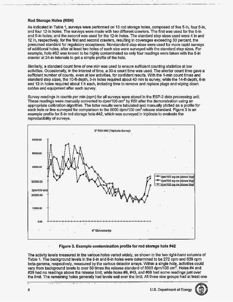
Rod Storage Holes (RSH) As indicated in Table 1 , surveys were performed on 13 rod storage holes, composed of five 5-in, four 6-in, and four 12-in holes. The surveys were made with two different crawlers. The first was used for the 5-in and 6-in holes; and the second was used for the 12-in holes. The standard step sizes used were 4 in and 12 in, respectively, for the first and second crawlers, resulting in coverages exceeding 30 percent, the presumed standard for regulatory acceptance. Nonstandard step sizes were used for more rapid surveys of additional holes, after at least two holes of each size were surveyed with the standard step sizes. For example, hole #52 was known to be highly contaminated so only four readings were taken with the 6-in crawler at 2 4 4 intervals to get a simple profile of the hole.
Similarly, a standard count time of one min was used to ensure sufficient counting statistics at low activities. Occasionally, in the interest of time, a 30-s count time was used. The shorter count time gave a sufficient number of counts, even at low activities, for confident results. With the l-min count times and standard step sizes, the 10-ft-depth, 5-in holes required a.bout 40 min to survey, while the 14-ft-depthI 6-in and 12-in holes required about 1 h each, including time to remove and replace plugs and wiping down cables and equipment after each survey.
Survey readings in counts per min (cpm) for all surveys were stored in the ESP-2 data processing unit. These readings were manually converted to dpm/lOO cm2 by RSI after the demonstration using an appropriate calibration algorithm. The latter results were tabulated and manually plotted as a profile for each hole or line surveyed for Comparison to the 5000 dpm/lOO cm2 release standard. Figure 3 is an example profile for 6-in rod storage hole #42, which was surveyed in triplicate to evaluate the reproducibility of surveys.
I 6" RSH #42 (Triplicate Survey)
50000.00
4 m . 0 0
30000.00
dpnVlOO 20000.00
IWW.00
0.00
4" Movements
-dpm/lOO sq cm (above bkg -Pdpm/lOO sq cm (above bkg
Figure 3. Example contamination profile for rod storage hole #42
The activity levels measured in the various holes varied widely, as shown in the two right-hand columns of Table 1. The background levels in the 5-in and 6-in holes were determined to be 272 cpm and 639 cpm beta-gamma, respectively, measured by the various detector arrays. Within a single hol;, activities could vary from background levels to over 50 times the release standard of 5000 dpm/100 cm . Holes #4 and #39 had no readings above the release limit, while holes #8, #43, and #68 had some readings just over the limit. The remaining holes generally had levels well over the limit. All three size groups had at least one

relatively uncontaminated hole and one or more highly contaminated holes. While the 5-in holes were lined with stainless steel and had a much smoother finish than the corroded carbon-steel-lined 6-in and 12-in holes, the three sets of holes exhibited similar ranges of activity. This result suggests little apparent effect on activity levels from the type of steel nor its appearance, assuming similar use patterns,
Survey results for the various rod storage holes could support decisions with respect to the holes. The activity levels observed in many of the holes indicate a need for substantial decontamination if they are to be left in place, while other holes would require little or no decontamination for release. These results could be used to identify the type and extent of decontamination that would be required to address the surveyed holes. Moreover, to the extent the 13 surveyed holes represent the entire 76-hole array, costs could be estimated to decontaminate and release the entire array.
Table 1. Summary of Pipe Crawler@ survey results for the CP-5 rod storage holes and portions of the 12-in vent lines
VL2-F I 12 I 4 8 40 223 I 41 1 302 I A cost analysis of the Pipe Crawler@ technology developed from the demonstration is presented in Section 5. Costs to characterize piping are compared to the baseline approach of pipe dismantlement and disposal. In the case of the rod storage holes, dismantlement would involve removing and size reducing the steel liners and coring out the unlined hole. The removed material would then be disposed as low-level waste. In this case, the savings accrued by Pipe Crawler@ surveys could be considered costs avoided for unnecessarily dismantling any holes in this manner that were established by survey to be suitable for free release. Further savings could be estimated for holes requiring only simple decontamination rather than dismantlement and coring.
Another consideration in favor of employing a decontaminate-and-survey approach here is that the rod storage holes are straight vertical holes with no joints, fittings, or obstructions. This makes the holes easy to survey and decontaminate if necessary. Also, such an approach would be far less disruptive to CP-5 activities and would pose lower overall risks to D&D workers and facility personnel.
U. S. Department of Energy 9

12-in Vent Lines The 12-in vent lines were a pair of cast iron air lines that serviced the reactor area. The lines were accessible from a shallow well in the vestibule area of the main floor outside the central containment area of CP-5. The lines run under the concrete floor of the facility, exiting to the northeast and making a 90' bend to the right at a point roughly 20 ft from the access point. The lines then run underground roughly 130 ft to the location of the former ventilation annex where the lines are currently capped and buried.
Surveys of the 12-in vent lines were performed with the same 12-in crawler using the same methodology as used in the 12-in rod storage holes. The results of the Pipe Crawler@ surveys for the 12-in vent lines are shown at the bottom of Table 1. The left-hand line (when facing the openings) was surveyed at 12-in steps with two readings at offset positions at each step. Readings were taken in the forward (VLI-F) and reverse (VLI-R) directions producing a duplicate survey of the initial portion of the line. Near the end of the reverse survey, one of the four detectors was pierced by a piece of debris. Readings over the last five ft of the reverse survey (near the access point) had to be corrected for the broken detector.
Time constraints limited the survey of the second line (VL2-F) to four steps at 8-in intervals using I-min count times to adjust for the broken detector. These readings provided a nominal measure of activity levels at the mouth of the second line.
Readings in the first line ranged only as high as twice background near the mouth, falling to background within a few ft. The few readings in the second line were near background. All readings for both lines were below levels requiring decontamination in the surveyed portions near the line starting point in CP-5. There is no apparent reason to expect levels to rise again in the remaining portions of the lines buried outside the facility. This conclusion is stronger for the first line than the second line where only a few measurements were made. These survey results in conjunction with a review of the process history of the two lines support at least a preliminary conclusion that the two 12-in vent lines require no remedial action.
The application of the Pipe Crawler@ technology in the vent lines exemplifies the kind of savings that might be accrued with the technology under the best circumstances. The demonstration surveys of the lines required only a few hours of work with a two-person crew and produced quality results that could support a decision that no further action was necessary. The demonstration performance suggests that substantial portions of the two lines could be surveyed in a day or two with sufficient quality to support release of the lines. The cost of such sufieys would compare very favorably to presumptive excavation and disposal of the two embedded 1504 lines.
10 U.S. Department of Energy

SECTION 4
TECHNOLOGY APPLICABILITY AND ALTERNATIVES
Co m pe ti n g Tech no I og ies
The baseline technology approach that competes with the Pipe Crawler@ is excavation and disposal of embedded piping. This approach may require extensive time and equipment to complete and may be potentially unnecessary if the pipe is uncontaminated.
Competing technologies include the following:
0 Pipe ExplorerTM, developed by Science and Engineering Associates, Inc. Also demonstrated as part of the CP-5 LSDP, Pipe ExploreP is a pipe characterization system that employs an air-tight membrane deployed from a canister with air pressure to line the interiors of pipes and to carry a tether to which detectors are attached. As the membrane deploys, detectors are towed along inside the membrane while measurement data is collected.
Multisensor Inspection and Characterization Robot for Small Pipes (MICROSPI) developed by Lockheed Martin Astronautics
Internal Duct Characterization System developed jointly by Idaho National Engineering and Environmental Laboratory, lnuktun Services, Ltd., and Automation Systems Associated, Ltd. (the latter two located in British Columbia) Small Pipe Characterization System (SPCS) developed by Foster-Miller, Inc.
0
0
0
A comparison of the relative characteristics, benefits, and limitations of these technologies will be provided in the LSDP final report.
Advantages of the Pipe Crawler@ technology include the following:
0 Pipe Crawler@ covers a wide range of pipe sizes, lengths and materials. 0
0
0
0
0
0
Surface coverage can be adjusted to any desired level to meet release requirements. Detector arrays have ample sensitivity relative to release limits. Detector array calibration is straightforward using the dispersed calibration sources.
Maintenance of precise detector geometry during surveys assures accurate readings. Calibration control charts, daily response checks, and detector array "knockdowns" lend further confidence to the reliability of measurements. Use of off-the-shelf detectors and other components simplifies repairs and increases up time.
The system generates little or no waste.
Limitations of the Pipe Crawler@ technology include the following:
0
0
0
Different-sized units are required for nominally different pipe sizes.
Cannot be used in pipes with standing water. Pipes must be free of obstructions or accessible from either end of an obstruction.
U. S. Department of Energy 11

0
0
0
Crawlers can become contaminated if used in untreated pipes. (However, only minor contamination of low-cost wheels occurred during the demonstration from loose corrosion in the untreated pipes.) Pipes accessible from only one end present difficulties in manipulating and recovering crawlers.
Technology is not particularly suited to detection of alpha contamination. Video inspection revealed mismatched pipe joints presenting potential snag points.
Technology Applicability
The Pipe Crawler@ technology is applicable to a wide range of pipe sizes and materials. Units have been built for pipes ranging in internal diameter from 2 in-I8 in. Most pipe materials can be surveyed, including steel, stainless steel, cast iron, and vitreous clay. The most important factors affecting the suitability of pipe systems are smoothness, types of joints, number and sharpness of bends, and freedom from obstructions and debris. Pipe lengths up to 200 ft can be surveyed if accessible from both ends. Single- end access reduces the range to about half and makes manipulation and recovery of the units more difficult. Drain pipes are particularly suited to the technology as they are typically fairly straight and uncomplicated systems and are often embedded, which increases the benefit of in-place management.
PatentdCommercializationlSponsor
No issues related to patents, commercialization, or sponsorship are pending. Pipe Crawler@ is a commercially available technology.
12 U.S. Department of Energy

SECTION 5
Introduction
This cost analysis compares the relative costs of the innovative and baseline technologies and presents information that will assist D&D planners in decisions about use of the innovative technology in future D&D work, This analysis strives to develop realistic estimates that represent D&D work within the DOE Complex, However, this is a limited representation of actual cost because the analysis uses only data observed during the demonstration. Some of the observed costs will include refinements to make the estimates more realistic, such as elimination of cost factors only applicable to demonstration of technologies. These are allowed only when they will not distort the fundamental elements of the observed data (e.g., do not change the productivity rate, quantities, and work elements, etc.) and eliminates only those activities which are atypical of normal D&D work. The CP-5 Large-Scale Demonstration Projecf, Summary of Results of Pipe Crawler Surveys for DOE'S LSDP at CP-5 provides additional cost information.
Methodology
This cost analysis for the Pipe Crawler@ innovative technology is based upon data collected during the demonstration that includes duration of activities, work crew composition, equipment used in the performance of the work, and supplies used. Data was collected into a predetermined structure to foster consistency with other demonstrations. Following collection of the data, team members from ICF Kaiser, USACE, and a D&D technical specialist from the.Argonne National Laboratory reviewed the costs and agreed on the approach used in the analysis. Those activities and costs that are for performance benchmarking (not a normal part D&D work) or that result from the demonstration nature of the contract are not included in this analysis.
The baseline technology was assumed to be dismantlement and removal of the contaminated pipes, and the cost estimate for that baseline is based upon a number of budget documents for the CP-5 including
0 Decommissioning Cosf Estimate for Placing fhe CP-5 Reacfor Faciify info Safe Storage (SAFSTOR);
0 Decommissioning Cosf Estimate for Full Decommissioning of the CP-5 Reactor Facility, prepared for Argonne National Laboratory; and
1996 activity cost estimates for the CP-5 decommissioning. 0
Since the baseline cost estimate is not based on observed data, extra effort is applied in setting up the cost analysis to assure unbiased and appropriate production rates and crew costs. Specifically, the previously mentioned team reviewed the activities and assumptions to be used in the baseline estimate to ensure a fair comparison with the Pipe Crawler@ demonstration.
The cost estimates for both the baseline and the innovative technology follow the Hazardous, Toxic and Radioactive Waste Remedial Action Work Breakdown Structure and Data Dictionary (USACE, 1996) for collecting costs into cost elements for reporting. For those cost elements associated with equipment that is assumed to be purchased by ANL or is owned by a vendor providing service to ANL, the hourly equipment rates that are used in this cost analysis include maintenance costs (if any) and allow for depreciation and the facility's capital cost of money (FCCM) and is computed in accordance with the Construction Equipment Ownership and Operating Expense Schedule (USACE EP-1110-1-B, 1995). For those cost elements associated with equipment that is assumed to be rented, that rental rate is used. It is reasonable to assume that the rental rate includes consideration of repair costs, depreciation, and FCCM.
U. S. Department of Energy 13

Cost Analysis
The DOE Complex presents a wide range of D&D work conditions because of the variety of functions and facilities. The working conditions for an individual job directly affect the manner in which D&D work is performed and, as a result, the costs for an individual job are unique. The innovative and baseline technology estimates presented in this analysis are based upon a specific set of conditions or work practices found at CP-5 and are presented in Table 2. This table is intended to help the technology user identify work differences that can result in cost differences. The original baseline estimate for CP-5 assumed 165 linear feet (lin ft) of buried 6-in pipe would require remediation. Based on conditions found in the field, a total of 262 lin ft of various\widths (5 in, 6 in and 12 in) was characterized using this technology. To ensure a fair and unbiased cost comparison, only 165 lin ft of the piping characterized was used for the comparative cost analysis. Since the costs were broken down to a per-linear-foot basis, and mobilization and demobilization costs for each respective technology are relatively fixed (see Figure 5 and Appendix C), this provided the most objective comparison of the two remediation methodologies.
Table 2. Summary of cost variable conditions
Material
Cost - variable I Pipe Crawler@ technology I Baseline technology
Location of test area purposes-see Appendix B) Rod storage and air lines for the
72 ft of 6-in carbon steel pipe 116 ft of 12-in carbon steel & cast iron pipe (165 ft of pipe was used for price comparison
surveyed (assumes coverage that NRC historically accepted is adequate for site and regulators) Three crawler sizes and crew of two vendor personnel plus one HPT. (HPT support is a separate line item in the summary table.)
Backhoe loader, concrete saw, decontamination technician, operator and HPT.
I reactor area I Only straight portions of pipe are Nature of work
surveyed and ends of 5-in -and 6- in pipe are capped with a plug that requires a crane for removal.
Work environment Level of contamination in the test areas
Level of contamination inside the pipes
Work performance Acquisition means
Complia-nce requirements
Equipment & crew
Demonstration area is not a radiation area. Any contamination that might be present is fixed.
Two pipes below release limits. Five pipes near release limits. Remaining pipes were well above release limits.
165 ft of 6-in pipe
Reactor area
Remove floor and excavate piping. Floor thickness of 1 ft. Assume only low-level radioactive contamination (no hazardous) so that there is not need to segregate sludge from pipe interior from the pipe (no need to try and reduce the volume of mixed waste).
Respiratory protection not required for concrete removal. Area previously decontaminated. Pipe removal requires protective clothing and respirators.
Productivity loss factor for pipe removal portion of work assumed to be 2.02 which would include protective clothing and respiratory protection.
Vendor provided service with I Local craft workers with rented mobilization of vendor equipment. I equipment. 25 percent of pipe surface area is I
14 U.S. Department of Energy

1 Pipe Crawler@ technology . I Crawler survey counts plus move to next increment is typically 1.2 min/increment with little variation based on timed observations. Video rate based on total time for video work divided by length of
Scale of production Process steps
End condition
Baseline technology Tyo ft?h for concrete saw cut. Four ft /h for concrete block removal. Seven ft3/h for pipe removal. Rates based on ANL budget documents.
1. Remove pipe cap. 2. Video pipe. 3. Survey pipe. 4. Performance check.
Pipe determined to meet free- release criteria remains in place. (Pipe not meeting release requirements will require further
The area is assumed to have been previously decontaminated, and this cost is not included in the baseline technology. However, the equipment used in the baseline technology must be decontaminated, and this cost is included in the estimate. The productivity loss factor accounts for inefficiencies associated with personal protective equipment (PPE), breaks, down time, etc.
1. Saw cut concrete along pipe length.
2. Cross cut into blocks. 3. Remove concrete blocks. 4. Cut pipe, and remove pipe and
soil. 5. Segregate contaminated soil. (This
occurs as it is removed.) 6. Dispose of waste. Pipe and concrete removed. (Open trench remains.)
Cost Conclusions For the conditions and assumptions of this demonstration, the innovative technology saves over 55 percent over the baseline alternative. A summary comparison is shown on Figure 4.
Figure 5 shows a comparison of the Pipe Crawle? to dismantlement per linear foot of pipe removed, based on the information and assumptions included in Appendix B. Fixed costs, including mobilization and demobilization, are assumed to be incurred regardless of the amount of pipe removed. Variable costs, including pipe characterization for the Pipe Crawler@ and dismantlement and waste disposal for the baseline technology, are reduced to a dollar-per-foot value. This figure should be taken as a rough indication on when the innovative technology becomes cost effective. Actual crossover will be greatly influenced by site-specific parameters. Additionally, the Pipe Crawler'? cost does not account for any pipe that may require dismantlement, based on the results of the Pipe Crawler@ characterization.
The amount of savings realized by using the Pipe Crawle? technology will vary depending upon site- specific conditions and work requirements. The most prominent of these factors that influence the savings are the size of the job and the ability to free release the pipe following the Pipe Crawle? survey. In situations where a pipe is surveyed and fails the free-release requirements, decontamination of the pipe or dismantlement and disposal of the pipe will be required. Approximately $13,000 of the Pipe Crawler@ cost (65 percent of the total in this demonstration) is for mobilization and demobilization, and these costs remain relatively constant despite the number of pipes surveyed. Those facilities with larger pipe survey quantities will distribute the mobilization and demobilization over a larger job.
U. S. Department of Energy 15

-I- $50,000
$40,000
$30,000
$20,000
$10,000
$- I I I I I I I I
Total Characterize/Dismantle Demob
In Innovative Pipe Crawler Baseline Dismantle & Remove I Figure 4. Cost analysis summary comparison.
lnnovitlvi Technology V8. Barellni Technology PIP. Cnwlervr.Oltmintlemint, $/It
I
Figure 5. Costllinear foot comparison of innovative Vs. baseline technology.
The total cost for the innovative technology is moderately sensitive to the mobilization and demobilization distance. Those sites located closer to the vendor will experience lower costs as compared with the more remote sites.
Establishing background radiation levels may be necessary where well documented survey results are required. The costs for establishing background is not included in this analysis, and that cost must be added for those situations. This will slightly reduce the potential savings but is not a large cost factor.
The baseline cost is sensitive to several parameters. Concrete slab thickness and width of the trench are significant cost drivers because changes in these dimensions result in changes to the concrete cutting production rate and waste disposal quantity. Additionally, the assumptions for the type of contamination are important factors in the total cost. If hazardous waste is present in addition to radioactive contamination, then efforts to scrape the sludge from the pipe interior may be required so that the pipe can be disposed as low-level radioactive waste rather than mixed waste. The waste assumptions in this
16 US. Department of Energy
analysis are relatively unconservative compared to many situations, and the potential savings from the Pipe Crawler@ will often be larger than reported in this analysis.
Three Pipe Crawler@ survey instruments are included in developing costs for the innovative technology. The number of pipes and the associated number of pipe crawler sizes will vary with the specific needs of the site. The cost of the equipment is relatively small; consequently, the total cost is not sensitive to the number of pipe crawler sizes required.
Because of the impact that site-specific conditions have on total costs, decision makers should tailor this analysis for their site by substituting the expected quantities, mobilization distance, etc. into Table B-1 of Appendix B.
U. S. Department of Energy 17

SECTION 6
0 DOEOrders -DOE 5400.5 -DOE 5480.1 1 -DOE 5820.2A
Radiation Protection of the Pubic and the Environment Radiation Protection for Occupational Workers Radioactive Waste Management
-1 926.28 -1926.52 -1 926.53 -1 926.55 -1 926.102 -1 926.103
Tools-Hand and Power Electrical - Definitions Personal Protective Equipment Occupational Noise Exposure Ionizing Radiation Gases, Vapors, Fumes, Dusts and Mists Eye and Face Protection Respiratory Protection
-191 0.95 -1 91 0.1 32 -1910.133 -1 91 0.1 34 -1 91 0.147
Machinery and Machine Guarding Hand and Portable Powered Tools and Other Hand-Held Equip. Electrical - Definitions Occupational Noise Exposure General Requirements (Personal Protective Equipment) Eye and Face Protection Respiratory Protection The Control of Hazardous Energy (LockouVTagout)
In addition to these regulations, the baseline technology would be subject to numerous OSHA regulations covering demolition, e w t i o n , and operation of heavy equipment. The waste form requirements for low- level wastes from either technology, as specified by disposal facilities used by ANL, include:
0
0
Hanford Site Solid Waste Acceptance Criteria: WHC-EP-0063-4 Barnwell Waste p g e m e n t Facility Site Disposal Criteria: S20-AD-010 Waste Acceptance Criteria for the Waste /solation Pilot Plant: WIPP-DOE-069
Since the Pipe Crawleq I technology is designed for the decontamination of structures, there is no regulatory requirement; to apply CERCLA's nine evaluation criteria. However, some evaluation criteria required by CERCLA, such as community acceptance, is briefly discussed below. Other criteria, such as cost and effectiveness! were discussed earlier in the document.
U.S. Department of Energy

Safety, Risks, Benefits, and Community Reaction
The Pipe Crawler@ technology is generally quite safe to operate. Identified hazards are those typical of working in industrial situations with electrical powered instrumentation. Physical hazards from working in confined or tight spaces associated with pipe systems are also present. Additionally, a high degree of physical exertion may be needed to maneuver the Pipe Crawler@ inside the pipes. Hazards associated with radiological contamination inside piping systems are of potential concern.
Using the Pipe Crawler@ technology as a technique to verify the absence of contamination eliminates the unnecessary steps of excavation, dismantlement, and disposal of uncontaminated piping. Risks to workers associated with excavation, heavy equipment usage, and possible exposure to radioactive piping can be eliminated.
The use of the Pipe Crawler@ technology rather than the baseline technology would have little impact on community safety, environmental, or socioeconomic issues. Any such impacts would be mostly favorable relative to the baseline technology due to reduced disruption of the affected facility, reduced physical hazards, reduced noise and dust emissions, and reduced waste hauling and disposal.
U. S. Department of Energy 19
. .
SECTION 7
ends.
readings. Pipes should be
Pipe Crawler@ is
I
I
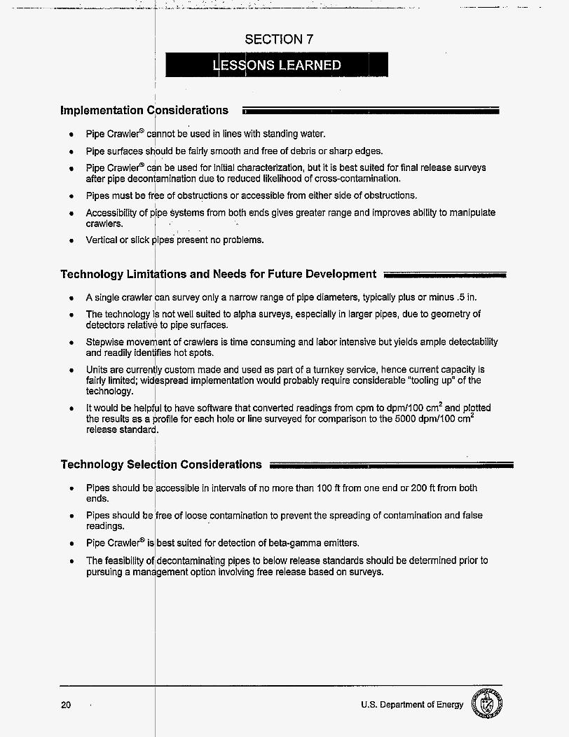
Implementation Considerations I ’
Pipe surfaces sdould be fairly smooth and free of debris or sharp edges. Pipe Crawler@ cannot be used in lines with standing water.
free of loose contamination to prevent the spreading of contamination and false
best suited for detection of beta-gamma emitters.
Pipe Crawler@ can be used for initial characterization, but it is best suited for final release surveys after pipe decontamination d u e to reduced likelihood of cross-contamination. Pipes must be frbe of obstructions or accessible from either side of obstructions. Accessibility of
Vertical or slick present no problems.
systems from both e n d s gives greater range and improves ability to manipulate crawlers.
I Technology Lirniktions and Needs for Future Development
A single crawler can survey only a narrow range of pipe diameters, typically plus or minus .5 in. The technology is not well suited to alpha surveys, especially in larger pipes, d u e to geometry of detectors relative to pipe surfaces. Stepwise movedent of crawlers is time consuming and labor intensive but yields ample detectability and readily identifies hot spots. Units a r e currenlly custom made and used as part of a turnkey service, hence current capacity is fairly limited; widespread implementation would probably require considerable “tooling up” of the technology. It would be helpf!ul to have software that converted readings from cpm to dpm/lOO cm2 and pl!tted the results as a profile for each hole or line surveyed for comparison to the 5000 dpm/l00 c m release standard.
Technology Selection Considerations
20 U.S. Department of Energy

APPENDIX A
Strategic Alliance for Environmental Restoration, CP-5 Large-Scale Demonsfration Project, Test Plan for the Demonsfration of the Pipe Crawler System at CP-5, November 1996.
Strategic Alliance for Environmental Restoration, CP-5 Large-Scale Demonstration Project, Technology Demonstration Summary Sheet, Pipe Crawler Radiological Surveying System, January 1997.
Strategic Alliance for Environmental Restoration, CP-5 Large-Scale Demonstration Project, Summary of Results of Pipe Crawler Surveys from DOES Large-Scale Demonsfration at CP-5, March 1997
Occupational Safety and Health Administration, (OSHA) 29 CFR 191 0, Occupational Safety and Health Standards, 1974.
Occupational Safety and Health Administration, (OSHA) 29 CFR 1926, Occupational Safety Regulation for Construction, 1979.
U. S. Department of Energy A-l

APPENDIX B
TECHNOLOGY COST COMPARISON I This Appendix contains definitions of cost elements, descriptions of assumptions, and computations of unit costs that are used in the cost analysis.
Innovative Technology: Pipe Crawler@
Mobilization
Transporting Personnel and Equipment Definition: Transport of vendor's personnel and equipment from New London, Connecticut to site by van, using o n e crew member as the driver. Although o n e crew member drove from Texas, the estimate a s s u m e s that all crew members travel from New London. Unloading Equipment Definition: Unloading the vendor's equipment includes time for crew to unpack equipment from the van and move the equipment to a staging area for radiological survey.
Assumptions: 1 h is required for unloading the equipment, based on experience gained during the demonstration. Surveying Equipment Definition: This cost element provides for radiological survey of the equipment by a site HPT to assure that contaminated equipment is not brought on site. Costs include crew stand-by time plus HPT labor.
Assumptions: 1 h is required for survey, based on experience gained during the demonstration. Training Definition: Site and Health and Safety-related training is required for subcontractor personnel.
Assumptions: O n e day is required for training, based on experience gained during the demonstration.
Characterization
Setting Up Each Morning Definition: This cost element includes time each morning to lay out the equipment and prepare for the day's work.
Assumptions: Set-up is assumed to be 10 min, based upon experience gained during the demonstration. Establish in g Background Definition: The background radiation level is established for each pipe size. Cost will vary depending upon the number of pipe sizes.
Assumptions: Based on vendor's experience, establishing background (equires 2 h per pipe size by a health physics technician (HPT). The Pipe Crawler@ has eight size increments, with diameters ranging from 2 in-24 in. Jobs will vary in the number of pipe sizes that will be required for establishing background. Additionally, many of the situations requiring characterization will not require a high level of accuracy in determining background. Consequently, the number of background counts that will be required for a n individual job will vary from zero (if no background is required) to eight (if all pipe sizes a r e encountered as part of the work).
U. S. Department of Energy B-1

it.
8-2 U.S. Department of Energy

Assumptions: T h e estimate a s s u m e s o n e 15-minute safety meeting each day (based on typical practice a t ANL).
Respirator Resp. Cartridges Booties Tyvek Gloves (inner) Gloves (outer pair) Glove (cotton Liner)
PPE Cost Per Day Definition: This cost element provides for PPE clothing used during the work activity. T h e following costs are applicable.
1,933 200 10 1 10.00 9.25 1 9.25 2 18.50
200 50.00 0.25 1 0.25 4 1 .oo 25 85.00 3.4 1 3.4 4 13.60 12 2.00 0.17 1 0.17 8 1.36
7.45 10 0.75 1 0.75
100 14.15 0.14 1 0.14 8 1.12
Equipment Quantityin Cost Cost No.of cost No. cost Box Per Each Reuses Each Used PerDay
Box Time Per
The PPE costs are predominantly from the ANL activity cost estimates for 1996. (Costs for outer gloves, glove liners, and respirator cartridges are from commercial catalogs.)
Assumption: Four changes each day per person (typical for ANL D&D work).
Demobilization
Surveying and Decontaminating Definition: This cost element provides for radiological survey of the equipment by a site HPT to assure that contaminated equipment does not leave the site and includes costs for decontamination. Costs include crew stand-by time plus HPT labor.
Assumptions: 4 h is required for survey, based on observed time from demonstration. Packing Equipment Definition: Loading the vendor's equipment includes time required for crew to pack equipment in the van.
Assumptions: O n e h is required for unloading the equipment. This is based on observed times from the demonstration. Transporting Personnel and Equipment Definition: Transporting vendor's personnel and equipment from the site to New London, Connecticut, using o n e crew member as the driver. Labor Cost for Surveying and Decontaminating Definition: T h e decontamination and survey of vendor equipment will have s o m e requirement for P P E by the crew and HPT conducting the decon work. This is assumed to b e similar to the previously defined PPE cost element.
U. S. Department of Energy 8-3

Mobilization
i . Labor I I I Truck Driver I 49.67 I 4 h l 149.01
I Total Equipment (rental) 1 I
Concrete Saw (baseline estimate) I 17.13
149.01
3 h 51.39
Flat Bed Truck rental (3 ton, Means Backhoe Loadei (baseline est.)
19971: ' I Miscellaneous i
I 60.78 19.00
5.00 3 h 15.00
182.34 76.00
Total:
Surveying Definition: This cost element consists of renting survey equipment and paying labor costs for an HPT to perform the survey.
Assumptions: The survey equipment is dropped off at a staging area. An HPT comes by later to perform the survey. Relevant bosts are presented below.
I
I Dismantlement I
Concrete Cutting Definition: This cost element provides for saw cutting the floor, which overlies the piping.
Assumptions: This analysis assumes the floor is cut using a diamond saw, which makes two parallel cuts mat are approximately 1 ft to 18 in apart and then cross cuts are made at intervals of approximately 38 in.
I
324.73

Respirator Resp. Cartridges Booties 200 Tyvek 25 Gloves (inner) 12 Gloves (outer pair)
Liner) Glove (cotton 100
PPE costs are predominantly from the ANL activity cost estimates for 1996. (Costs for outer gloves, glove liners, and respirator cartridges are from commercial catalogs.)
Assumption: D&D work at ANL typically requires four changes each day per person. -
1,933 200 10 1 10.00 9.25 1 9.25 2 18.50
50.00 0.25 1 0.25 4 1 .oo 85.00 3.4 1 3.4 4 13.60 2.00 0.17 1 0.17 8 1.36
7.45 10 0.75 1 0.75
14.15 0.14 1 0.14 8 1.12
U. S. Department of Energy 5 5

Clean Waste (Concrete)
1992) assumes a 150 percent swell factor and 0.05 ft /ft of contaminated soil.
;B:6 " U.S. Department of Energy

Cost Analysis
Innovative Technology: The Pipe Crawler@
Costs for demonstrating the Pipe Crawler@ innovative technology are based on operating the device at two encased pipe locations-the rod storage area, and area containing air lines connecting to the reactor area. The Pipe Crawler@ technology consists of mobilization, site-specific training, set-up, establishing background counts, removing any caps or obstructions to the pipeline entrance, videotaping the pipeline interior, radiological survey of the pipeline interior, moving and setting up on the next pipe, conducting performance checks, and demobilization. The projection of demonstration costs to reflect a more realistic cost for that scope of work include a number of assumptions that make that projection possible. These assumptions are shown below:
0
0
0
Survey of pipe consists of one pass through the pipe. Time requirements associated with multiple passes through the pipe to check survey repeatability are ignored since this should not be necessary for typical D&D work situations. Those surveys where alternative instrument movement distances are used are not considered in this analysis; only those surveys covering approximately 25 percent of the pipe interior surface are used because the Nuclear Regulatory Commission (NRC) has previously accepted the 25 percent coverage rate. Surveys of pipes using less than I-min count times are not included since this is not the currently accepted standard. Alternate count times were performed to facilitate comparison with the standard I-min count. Surveys having variations in normal procedures (such as not being able to rotate the detector to the off-set position) are not included since this does not conform to standard practice. Seven hours of meetings (associated with planning the demonstration, debriefing for an alpha contamination incident, and data collection questioning) are excluded. Included are the morning safety meetings (1 5 min per day of work). The time required to convert a 6-in-diameter Pipe Crawler@ to fit a 5-in-diameter pipe is omitted from this analysis, Normal work practice is better represented by including the equipment cost for a 5-in, 6-h, and 12-in-diameter Pipe Crawler@ rather than show the cost for two pipe crawlers and time required to convert from one size to the other. Work will be performed as a vendor-provided service, rather than purchase the equipment and perform work with local craft because the following operation issues made ownership prohibitive: - The number of Pipe Crawler@ survey instruments required to cover the potential range in pipe
sizes is large. - The expense of the calibration standards is high. - Unique skill is required for some of the periodic maintenance of the equipment.
Equipment hourly rates were based upon the depreciated purchase price and maintenance cost of the equipment reported by the vendor. The labor rates are based on rates provided by the vendor. Depreciation is based on a cost of money at 6.375 percent, determined by the Secretary of the Treasury pursuant to Public Law 92-41, 85 Statute 97 and discounted to 4.78 percent, service life of three-five years (depending on the individual piece of equipment), straight-line depreciation, repair cost for periodic maintenance, and assumed use of 800 hlyr. Full-time HPT support is included.
A productivity loss factor (PLF) multiplies the work time to account for the necessary activities that do not directly accomplish work (e.g., work breaks) or to account for conditions that result in decreases in production rates (e.g., heat stress). Since the nonproductive activities in the demonstration are atypical of normal D&D work, most of these activities have been screened out of this analysis. In an effort to restore the costs to a more realistic estimate of typical D&D work, a PLF from the baseline is used (from ANL documentation of budgets developed in 1992) and is 1 .I 0 based on the factors as shown.
U. S. Department of Energy 6-7

-
1 .oo
B-8
= Subtotal X I Respiratory Protection 1 .oo
I
U.S. Department of Energy
I
=Subtotal 1 .oo x i Breaks 1.10
=Total 1.10 I
0 Procurement c i s t of 9.3 percent is added to the hourly rate for the vendor-owned equipment and the vendor labor to account for the ANL charge to the project for administration of the procurement contract. I
i The cost for PPE used during the demonstration is based upon typical practice and equipment a t ANL (four pairs of P P E used each day per person). Since this is a n assumed rate rather than a n observed quantity, the cost is computed based on the total duration of work in the controlled a rea plus the time required for decontamination of the equipment a t the completion of the work.
During the course of )he demonstration, it w a s observed that the duration and effort required for the radiological survey was consistent for all pipes for the duration of the demonstration. Costs for mobilization and demobilization will vary from site to site depending upon the mobilization distance.
The activities, quantiths, production rates, and costs observed during the demonstration are shown in Table B-1 , Innovative iTechnology Cost Summary.

Table B-1 Innovative Technology Cost Summary
Unit Cost (UC) Total Unit Total Work Breakdown Structure Eauimnent Other Total Quantity of cost
(WBS) Rate UC (TQ) Measure (TC) note Comments
Transport Personnel & Equip 10 $ 195 10 $ 78 $2,731 2 Day $ 5,461 New London, CT. to Chicago (Department of MOBILIZATION (WBS 331.01) Subtotal $ 8,261
Transportation (DOT) restrictions approx. 500 miles per day & 10 Nday) crew of 2 vendor personnel (consistent for remainder of table)
Unload Equipment (Equip) 1 $ 195 I $ 78 $ 273 1 Each $ 273 Survey-In Equip $ - 1 Each $ 342
Vendor Crew Stand-By I $ 195 1 $ 78 $ 273 Vendor Labor & Equipment rates HPT Support 1 $ 56 $ - $ 1 3 $ 6 9 ANL's Health Physics Technician (HPT) labor and
1/4 ft3 of Low Level waste disposal for swipes @ $52.78/ft3
Worker Training 8 $ 195 8 $ 78 $2,185 1 EY--_- $ 2,185 Site training plus Rad Worker II Training
Set-Up Each Morning 0.167 $ 195 0.167 $ 78 $ 46 3 Day $ 137 10 min of set-up per day of work Establish Background $ - $ - Assume 2 h l pipe size for HPT to establish
background (not performed for this demo) Access Pipeline 15 Pipes $ 441 Lift 500 pound c a p off rod storage pipe
Vender Stand-By 0.083 $ 195 0.083 $ 78 $ 23 Lift Cap off Pipe 0.083 $ 40 0.083 $ 40 $ 7 ANL crane operator and overhead crane
Video Pipeline 0.012 $ 195 0.012 $ 78 $ 3 212 Ft $ 683 Pipesurvey- lOin&Smaller 0.059 $ 195 0.059 $ 78 $ 16 49 Ft $ 792 1.2 min for counting + advancement per 4 in Pipe Survey- Largerthan 10 in 0.02 $ 195 0.02 $ 78 $ 5 116 Ft $ 628 1.2 min. for counting + advancement per 12 in Set-Up & Move to Adjacent 0.004 $ 195 0.004 $ 78 $ 1 709 Pipes $ 765 10 min to remove cables and move Set-Up & Move to Remote 1.25 $ 195 1.25 $ 78 $ 341 1 Each $ 341 Move from inside building to outside Performance Check 0.084 $ 195 0.084 $ 78 $ 23 5 Each $ 115 5 min per check per day per pipe size HPT Support 15.17 $ 56 $ 850 1 Each $ 850 HPT presence during performance of work Productivity Loss Factor(PFP) 3.03 $ 195 3.03 $ 78 $ 827 1 Each $ 827 Duration in controlled area X 10 percent
H&S/Project Meetings 0.25 $ 195 0.25 $ 78 $ 68 2 $ 137 15 midday safety meeting (typical for ANL) PPE $ - $ 4 6 $ 4 6 6 Pa!--- - . $ 278 Assumed cost per person per day of $46.33
PIPE CHARACTERIZATION (WBS 331.17) Subtotal $ 5,992
(PLF=1.10)
DEMOBlLlZATlON (WBS 331.21) Subtotal $ 6,104
Vendor Labor & Equipment rates Survey Equip. & Decon $ - 1 Each $ 342
Vendor Crew Stand-By 1 $ 195 I $ 78 $ 273 HPT Support 1 $ 56 $ 13 $ 69 Same as Mobilization, HPT Support
Pack Equipment 1 $ 195 I $ 78 $ 273 1 Each $ 273 Personnel & Equip. Transp. 10 $ 195 10 $ 78 $2,731 2 Day $ 5,461 Same as Mobilization, Personal & Equip Trans; Productivity Loss Factor 0.1 $ 195 0.1 $ 78 $ 27 1 Each $ 27 Applied to decontamination & Survey of Equip
Note: TC = UC TQ TOTAL: $20,358
U. S. Department of Energy B-9
activities.
B-10
Table B-2, Baseline
U.S. Department of Energy
T,echnology Cost Summary.

Vork Breakdown Structure (WBS)
Subtotal
Unit Cost (UC) Total Unit Labor Eauiment Other Total Quantity of
H Rate H Rate UC (TQ) Measure
Transport and Unload Equip. O $ -
O $ - 1 $ 56.00
Survey-In Equipment Equipment Stand By HPT Support
O $
4 $331.64 $
- Concrete Block Removal ' 0.25 $ 73.45' 0.25 $ 82.91' I $ 39 Remove Pipe & Soil 0.143 $ 73.45 0.143 $ 82.91 $ 22 Set-Up & Move Remote 1 $ 73.45 1 $ 82.91 $ 156 HPT Support 148.3 $ 56.00 0 $ - $ 8,307 Productivity Loss (Concrete) 12.38 $ 73.45 12.38 $ 82.91 $ 1,935
Iismantlement (WBS 331.17) Subtotal Concrete Cuttina I 0.5 $ 73.451 0.5 $ 82.911 I $ 781 1651 Ft
165 Ft 165 Ft
1 Each 1 Each 1 Each
$ '156 $ 8,307 $ 1,935
$ 3,763
$ 899 ,
HPT presence during performance of work Work duration in controlled area X 10 percent Productivity Loss Factor (PLF )=1.10 Duration in controlled area X 1.02 percent (PLF=2.02) 15 min/day health and safety (H&S) meeting (typical ANL)
8 $ 56.00 I O $ -I !fi 82*9
Productivity Loss (Pipe)
H&S/Project Meetings
Personal Protection Equip.
$ 3,763
$ 139
I
24.07 $ 73.45 24.07 $ 82.91
0.25 $ 73.45 0.25 $ 82.91
0 $ - 0 $ - $ 13!
Equipment Stand By HPT Support
I I I I I I Productivitv Loss Factor I 0.08 $ 56.001 0.08 $ 82.911 I $ 111 11 Each $ 11
$ 46 $ 325 $ 3,729 $ 35
Personal Protection Equip. I 0 $ -1 0 $ -1s 46 Load and TransDort EauiD. I 0 $ -I 0 $ -I $ 325
waste disposal for cleaning @ $52.78/ft3 Productivity Loss Factor of 1 . I O for decon $46.33/person/day for 1 persons for 1 day Same as Mobilization, Transport & Load Equil
$O.14/ft4 unit rate for ANL clean waste
$ 46 $ 325
Waste Disposal (WBS 331.18) Subtotal Clean Waste (Concrete) I I I $ 0.141$ 0.141 2481 Cubic Ft
~~ ~
1 Day 1 Each
Waste Disposal (Solid LL) $52.78 $ 52.78 70 CubicFt
TOTAL Note: TC = UC * TQ
I
Total cost
(TC) note $ 1,72a $ 325
$ 1,396
$ 41,296 $ 12.90C $ 6145C $ 3.689
Comments
Transport equipment (Equip.) from local renta , includes 4 h truck hauling, teamster and stand by for saw and backhoe for 3 h
Stand by cost for saw and backhoe for 4 h ANL's Health Physics Technician (HPT) labor & 114 ft3 of low level (LL) waste disposal for swipes @ $52.78/ft3
2 Wh Droduction rate 4 Wh production rate 7 Wh Droduction rate
$ 3,197 $ 1,516 '$ 1,164
.-. $46.33/person/day for 3 persons for 23 days
Stand by during decontamination (decon.) ANL's HPT labor rate & 1 ft3 of Low Level
/disposal $ 3,6951Assume 150 percent bulking for 6 in pipe and
.05 cubic Wft contaminated soil at $52.78/ft3 unit rate for ANL LL waste disposal
$48,292
U. S. Department of Energy 8-1 1

APPENDIX C
ACRONYMS AND ABBREVIATIONS I- ALARA ANL-E cm CPm CP-5 D&D DDFA Decon. DOE DOT
Equip. ESH FCCM f l GM
H&S HP H PT IH in lin ft LSDP min NRC OSHA PLF PPE Radial Services, Inc. RSH TQ uc USACE .WBS WMO Yr
dPm
n
as low as reasonably achievable Argonne National Laboratory-East centimeter(s) counts per minute Chicago Piled decontamination and decommissioning Deactivation and Decommissioning Focus Area Decontamination US. Department of Energy US. Department of Transportation disintegrations per minute Equipment Environment, Safety, and Health facility’s capital cost of money foot (feet) Geiger Mueller hour(@ Health and Safety health physics health physics technician industrial hygiene inch(es) linear foot (feet) Large-Scale Demonstration Project minute(s) Nuclear Regulatory Commission Occupational Safety and Health Administration productivity loss factor personnel protective equipment RCI rod storage holes total quantity unit cost U.S. Army Corps of Engineers Work Breakdown Structure waste management operations YeaW
U. S. Department of Energy c-1