pilot operated main valves for regulating pressure and ... · technical leaflet pilot operated main...
TRANSCRIPT

Pilot operated main valves for regulating pressure and temperatureType PM
Technical leafletREFRIGERATION AND AIR CONDITIONING

� RD4XA5�� → DKRCI.PD.HL0.A1.�� / 5�0H0184 Danfoss A/S (AC-DSL / MWA), 05 - �006
Technical leaflet Pilot operated main valves for regulating pressure and temperature, type PM
Contents Page
Introduction. . . . . . . . . . . . . . . . . . . . . . . . . . . . . . . . . . . . . . . . . . . . . . . . . . . . . . . . . . . . . . . . . . . . . . . . . . . . . . . . . . . . . . . .3
Features . . . . . . . . . . . . . . . . . . . . . . . . . . . . . . . . . . . . . . . . . . . . . . . . . . . . . . . . . . . . . . . . . . . . . . . . . . . . . . . . . . . . . . . . . . . .3
Design . . . . . . . . . . . . . . . . . . . . . . . . . . . . . . . . . . . . . . . . . . . . . . . . . . . . . . . . . . . . . . . . . . . . . . . . . . . . . . . . . . . . . . . . . . . . .4
Design, function . . . . . . . . . . . . . . . . . . . . . . . . . . . . . . . . . . . . . . . . . . . . . . . . . . . . . . . . . . . . . . . . . . . . . . . . . . . . . . . . . . . .5
Function examples . . . . . . . . . . . . . . . . . . . . . . . . . . . . . . . . . . . . . . . . . . . . . . . . . . . . . . . . . . . . . . . . . . . . . . . . . . . . . . . . .7
Material specification . . . . . . . . . . . . . . . . . . . . . . . . . . . . . . . . . . . . . . . . . . . . . . . . . . . . . . . . . . . . . . . . . . . . . . . . . . . . . 16
Flange connections . . . . . . . . . . . . . . . . . . . . . . . . . . . . . . . . . . . . . . . . . . . . . . . . . . . . . . . . . . . . . . . . . . . . . . . . . . . . . . . 17
Ordering PM valves . . . . . . . . . . . . . . . . . . . . . . . . . . . . . . . . . . . . . . . . . . . . . . . . . . . . . . . . . . . . . . . . . . . . . . . . . . . . . . . 19
Dimensions and weights . . . . . . . . . . . . . . . . . . . . . . . . . . . . . . . . . . . . . . . . . . . . . . . . . . . . . . . . . . . . . . . . . . . . . . . . . . �0
Accessories . . . . . . . . . . . . . . . . . . . . . . . . . . . . . . . . . . . . . . . . . . . . . . . . . . . . . . . . . . . . . . . . . . . . . . . . . . . . . . . . . . . . . . . �1
Nominal capacities . . . . . . . . . . . . . . . . . . . . . . . . . . . . . . . . . . . . . . . . . . . . . . . . . . . . . . . . . . . . . . . . . . . . . . . . . . . . . . . �4
Liquid line . . . . . . . . . . . . . . . . . . . . . . . . . . . . . . . . . . . . . . . . . . . . . . . . . . . . . . . . . . . . . . . . . . . . . . . . . . . . . . . . . . . . �4
Pumped liquid line. . . . . . . . . . . . . . . . . . . . . . . . . . . . . . . . . . . . . . . . . . . . . . . . . . . . . . . . . . . . . . . . . . . . . . . . . . . . 30
Wet suction line. . . . . . . . . . . . . . . . . . . . . . . . . . . . . . . . . . . . . . . . . . . . . . . . . . . . . . . . . . . . . . . . . . . . . . . . . . . . . . . 34
Dry suction line . . . . . . . . . . . . . . . . . . . . . . . . . . . . . . . . . . . . . . . . . . . . . . . . . . . . . . . . . . . . . . . . . . . . . . . . . . . . . . . 39
Discharge line . . . . . . . . . . . . . . . . . . . . . . . . . . . . . . . . . . . . . . . . . . . . . . . . . . . . . . . . . . . . . . . . . . . . . . . . . . . . . . . . 45

Danfoss A/S (AC-DSL / MWA), 05 - �006 RD4XA5�� → DKRCI.PD.HL0.A1.�� / 5�0H0184 3
Technical leaflet Pilot operated main valves for regulating pressure and temperature, type PM
Introduction
Features Can be used for all normal, non-flammable refrigerants, including R 717, and non-corrosive gases/liquids - assuming seals of the correct material are used.
Large range of flanges with connection dimensions in accordance with standards: DIN, ANSI, SOC, SA and FPT.
Performs as a multifunction valve when several pilot valves are connected to the same main valve.
All pilot valves can be used on all sizes of PM main valves. They can be screwed direct into the main valve so that there is no need for weld or solder connections, or separate pilot lines.
The valve has a pressure gauge connection so that inlet pressure can be measured.
The valve has a built-in filter and a teflon seat to give excellent tightness.
The PM main valve top cover can be oriented in any direction without the function of pilot valves being affected.
The valve can be equipped with an AKS 45 electronic position indicator as an accessory.
PM valves are pilot operated main valves for regulating pressure and temperature in refrige-ration systems.
PM main valves can be used on the high and low-pressure sides, in wet and dry suction lines, and in liquid lines without phase change (i.e. where no expansion takes place in the valve).
The function of a PM valve depends solely on the pilot pressure applied to the valve, either from pilot valves or in the form of external pilot pressure.
PM 1 has one connection for pilot pressure/pilot valve, while PM 3 has three pilot pressure/pilot valve connections.
The associated Danfoss pilot valves can either be screwed direct into the main valve or be
connected via an external pilot line. Several pilot valves can be used on one main valve to give a large number of different functions.
The PM valve top cover has a pressure gauge connection so that the inlet pressure can be measured when, for example, main valve function must be set or adjusted in relation to the system regulation performed by the pilot valves.
The spindle in the top cover of the main PM valve can be used to manually open and close the valve (although PM 65-1�5 cannot be opened fully in this way).
The main valve bottom plug can be replaced by an AKS 45 electronic position indicator so that the position of the regulating cone can be read electronically.

4 RD4XA5�� → DKRCI.PD.HL0.A1.�� / 5�0H0184 Danfoss A/S (AC-DSL / MWA), 05 - �006
Technical leaflet Pilot operated main valves for regulating pressure and temperature, type PM
Design
Technical data
Connections There is a very wide range of connection possibilities with PM main valves:
Welding, DIN (�448)
Welding, ANSI (B 36.10)
Welding socket, ANSI (B 16.11)
Solder connection, DIN (�856)
Solder connection, ANSI (B 16.��)
FPT internal thread, NPT (ANSI/ASME B 1.�0.1)
PM main valves are designed as pilot operated valves that can be fully opened with a very small differential pressure (0.� bar/�.9 psi). The valve design means that it will only fully close in the direction of flow.
Pressure Equipment Directive (PED)The PM-valves are approved in accordance with the European standard specified in the Pressure Equipment Directive and are CE marked. For further details / restrictions - see InstallationInstruction
PM 1 will accept one pilot valve mounted direct on the valve, while PM 3 will accept three pilot valves.
Two of the PM 3 pilot valve connections (S1 and S�) are series connected while the third pilot connection (P) is connected in parallel. Thus, with different combinations of pilot valves it is possible to obtain a very large number of different functions from one PM main valve.
The PM main valve has a logarithmic or v-shaped throttle cone that ensures optimum regulating accuracy.
The PM main valve top cover can be oriented in any direction without the function of pilot valves being affected.
Valve bodyEN-GJS-400-18-LT
SealsDo not contain asbestos.
Refrigerants Can be used for all normal, non-flammable refrigerants, including R 717, and non-corrosive gases/liquids - assuming seals of the correct material are used. Use with flammable hydrocarbons cannot be recommended; please contact Danfoss.
Temperature range –60/+1�0°C (–76/+�48°F).
Surface PM 5 - 65: The external surface is zinc-chromated to give good protection against corrosion. PM 80 - 1�5: The surface of the PM 80 - 1�5 is treated with a multi-layer painting.
Pressure range The valve is designed for: Max. working pressure: �8 bar g (406 psig) Test pressure: 4� bar g (609 psig) Opening differential pressure: Fully open: Min. 0.� bar g (min. �.9 psig) Max. (MOPD), solenoid valves only (10 W a.c. and �0 W d.c.): �1 bar g (305 psig)
Built-in filter PM 5 - 40 mesh: 950 µ (18 mesh/in.) PM 50 - 1�5 mesh: 1500 µ (10 mesh/in.)
PM valves
Nominal bore DN≤ �5 (1 in.) DN 3�-1�5 mm (11/4 - 5 in.) DN 150 mm (6 in.)
Classified for Fluid group I
Category Article 3, paragraph 3 II III

Danfoss A/S (AC-DSL / MWA), 05 - �006 RD4XA5�� → DKRCI.PD.HL0.A1.�� / 5�0H0184 5
Technical leaflet Pilot operated main valves for regulating pressure and temperature, type PM
Design, function
PM1
The PM main valve is a pilot operated valve whose function is determined by the pilot valve used. The main valve with pilot valve(s) controls refrigerant flow by modulation or on/off in accordance with the pilot valve or main valve status.
The degree of opening of the main valve is deter-mined by the pressure difference (differential pressure) between pressure p�, which acts on top of the servo piston (�4), and pressure p3, which acts on the underside of the servo piston.
If this pressure difference is 0, the main valve will be fully closed.If the pressure difference is 0.� bar (�.9 psi) or more, the main valve will be fully open.At pressure differences (p� - p3) between 0.07 bar (1 psi) and 0.� bar (�.9 psi), the degree of opening will be correspondingly proportional.
The shape of the throttle cone (1�) is logarithmic, which gives an ideal regulation characteristic to pilot operated main valves. Because of valve body channel (1b), pressure p3 acting on the underside of the servo piston (�4) is equal to the main valve discharge pressure p4.The degree of opening of the main valve is thus controlled by the application of a pressure, p�, on top of the servo piston which is equal to or greater than the discharge pressure, p4.
p� = p4 ∼ closedp� = p4 + 0.� bar (�.9 psi)~ fully openp4 ≤ p� ≤ p4 + 0.� bar (�.9 psi) ~ proportional degree of opening.
PM3
PM 1 and PM 3 1. Valve body 1 a Channels in valve body 1 1 b Channels in valve body 1 10. Valve spindle 11. Teflon valve plate 1�. Throttle cone �1a. Equalisation hole in servo piston �4 ��. Locking ring �4. Servo piston �4a. Gasket 30. Bottom cover 33. Strainer 36. Plug 40. Cover 40 a Channels in cover 40 40 b Channels in cover 40 40 c Channels in cover 40 40 d Channels in cover 40 44. Pressure gauge connection 60. Manual operating spindle 61. External pilot connection S I, S II Pilot valve connections in series connection holes P. Pilot valve connection in parallel connection hole
The maximum pressure, p�, that can be built up on the top of the servo piston (�4) normally corresponds to the pressure, p1, acting on the main valve inlet side. Inlet pressure p1 is led, via the drilled channels (1a, 40a, 40b, 40c, 40d) in the valve body (1) and cover (40) through the individual pilot valves and onto the top of the servo piston (�4).The degree of opening of the individual pilot valves determines the size of pressure p� and thus the degree of opening of the main valve, i.e. the equalisation hole (�1a) in the servo piston (�4) ensures that pressure p� is balanced in accordance with the degree of opening of the pilot valve.
Note: When main valve type PM 3 is used with an external pilot connection (61), the internal pilot pressure will be shut off.
The PM 1 main valve can be fitted with just one screwed-on pilot valve. The degree of opening of the main valve will be in accordance with the control status from the pilot valve.
PM 1 is fully closed when the pilot valve is fully closed and fully open when the pilot valve is fully open. Otherwise the degree of opening of the main valve is proportional to the degree of opening of the pilot valve.
The PM 3 main valve can be fitted with either one, two, or three pilot valves so that up to three regulating functions are possible.

6 RD4XA5�� → DKRCI.PD.HL0.A1.�� / 5�0H0184 Danfoss A/S (AC-DSL / MWA), 05 - �006
Technical leaflet Pilot operated main valves for regulating pressure and temperature, type PM
Design, function(continued)
The relations between the functions of the screwed-in pilot valves are as follows:A. The pilot valves fitted in ports SI and SII are connected in series. The PM 3 main valve will be fully closed if just one of the series-connected pilot valves is closed. The main valve can only open if both pilot valves are fully open at the same time.B. The pilot valve fitted in port P is connected in parallel to the pilot valves in ports SI and SII.
The PM3 main valve will be fully open if the pilot valve in P is fully open, irrespective of the degree of opening of pilot valves SI and SII.The PM 3 main valve will be fully closed if the pilot valve in P is fully closed and at least one of the valves in SI or SII is fully closed at the same time.The relation between the pilot valves in ports SI, SII and P is shown in the table above.
If the PM 3 is not fitted with three pilot valves, the unused port(s) must be sealed off with a blanking plug.If the blanking plug is fitted as an assembled unit, A + B, the channels from the port concerned will be closed.If only the top part, A, of the plug is fitted, the channels from the ports in question will be open.If the degree of opening of the PM main valve is not to be a function of the main valve inlet pressure, or if more than three regulating functions are required, ports SI, SII or P can be fitted with a nipple for the connection of external pilot pressure. This applies to both PM 1 and PM 3.Pressure p� on top of the servo piston will then be determined by the pressure to which the external pilot line is connected. The main valve function will be determined by the pilot valves fitted in that external pilot line. Pilot valves installed in external lines must be mounted in a type CVH housing.
Depending on the function of the pilot valves, the PM regulating characteristic becomes: on/off proportional integral or cascade.
PM main valves are therefore especially suitable for all forms of temperature and pressure regulating systems.
Blanking plug A Blanking plugA + B
Pilot valve PM 3main valve
SI SII P
Open Open Closed Open
Open Open Open Open
Open Closed Closed Closed
Open Closed Open Open
Closed Open Closed Closed
Closed Open Open Open
Closed Closed Closed Closed
Closed Closed Open Open

Danfoss A/S (AC-DSL / MWA), 05 - �006 RD4XA5�� → DKRCI.PD.HL0.A1.�� / 5�0H0184 7
Technical leaflet Pilot operated main valves for regulating pressure and temperature, type PM
Function examples
Example no. 1-1 Products
Constant pressure regulation.–0.66 to 7 bar g (19.5 in. Hg to 10� psig).
1 × PM 11 × CVP (LP)� × flanges
Example no. 1-� Products
Differential pressure regulation.0 to 7 bar g (0 to 10� psig).
1 × PM 11 × CVPP (LP)� × flanges
Example no. 1-3 Products
Temperature regulation.–40 to 60°C (–40 to 140°F).Opening at rising temperature.Pressure independent.
1 × PM 11 × CVT� × flanges
Example no. 1-4 Products
Temperature regulation.–40 to 60°C (–40 to 140°F).Closing at rising temperature.Pressure independent.
1 × PM 11 × CVTO� × flanges
Example no. 1-5 Products
On/off regulation (solenoid valve).
1 × PM 11 × EVM� × flanges

8 RD4XA5�� → DKRCI.PD.HL0.A1.�� / 5�0H0184 Danfoss A/S (AC-DSL / MWA), 05 - �006
Technical leaflet Pilot operated main valves for regulating pressure and temperature, type PM
Function examples (continued)
Example no. 1-6 Products
Regulation with external control pressure.
1 × PM 11 × nipple for external control pressure� × flanges
Example no. 1-7 Products
Constant pressure regulation.–0.66 to �8 bar g(19.5 in. Hg to 406 psig).
1 × PM 11 × CVP (HP)� × flanges
Example no. 1-8 Products
Differential pressure regulation.0 to �� bar g (0 to 319 psig).
1 × PM 11 × CVPP (HP)� × flanges
Example no. 1-9 Products
On/off regulation (solenoid valve).
1 × PM 11 × EVM-NO (1� W coil)� × flanges
Example no. 1-10 Products
Crankcase pressure regulation.(Max. suction pressure regulation) –0.45 to 7 bar g(13.3 in. Hg to 10� psig).
1 × PM 11 × CVC� × flanges

Danfoss A/S (AC-DSL / MWA), 05 - �006 RD4XA5�� → DKRCI.PD.HL0.A1.�� / 5�0H0184 9
Technical leaflet Pilot operated main valves for regulating pressure and temperature, type PM
Function examples (continued)
Example no. 1-11 Products
Electronically controlled media temperature regulation.–1 to 8 bar g(0 in. Hg to 116 psig).
1 × PM 11 × CVQ� × flanges
Example no. 3-1 Products
Constant pressure regulation combined with electrical shut off.–0.66 to 7 bar g(19.5 in. Hg to 10� psig).
1 × PM 31 × blanking plug1 × CVP (LP)1 × EVM� × flanges
Example no. 3-� Products
Constant pressure regulation combined with electrical wide open.–0.66 to 7 bar g(19.5 in. Hg to 10� psig).
1 × PM 31 × blanking plug1 × CVP (LP)1 × EVM� × flanges
Example no. 3-3 Products
Constant pressure regulation combined with electrical shut off and wide open.–0.66 to 7 bar g(19.5 in. Hg to 10� psig).
1 × PM 31 × CVP (LP)� × EVM� × flanges
Example no. 3-4 Products
Constant pressure regulation with change-over between two preset evaporating pressures.–0.66 to 7 bar g(19.5 in. Hg to 10� psig).
1 × PM 3� × CVP (LP)1 × EVM� × flanges

10 RD4XA5�� → DKRCI.PD.HL0.A1.�� / 5�0H0184 Danfoss A/S (AC-DSL / MWA), 05 - �006
Technical leaflet Pilot operated main valves for regulating pressure and temperature, type PM
Function examples (continued)
Example no. 3-5 Products
External control pressure with electrical shut off combined with constant pressure regulation.–0.66 to 7 bar g(19.5 in. Hg to 10� psig).
1 × PM 31 × nipple for external control pressure1 × CVP (LP)1 × EVM� × flanges
Example no. 3-6 Products
Constant pressure regulation with external control pressure combined with electrical wide open.–0.66 to 7 bar g(19.5 in. Hg to 10� psig).
1 × PM 31 × nipple for external control pressure1 × CVP (LP)1 × EVM� × flanges
Example no. 3-7 Products
Constant pressure regulation with electrical shut off combined with external control pressure.–0.66 to 7 bar g(19.5 in. Hg to 10� psig).
1 × PM 31 × nipple for external control pressure1 × CVP (LP)1 × EVM� × flanges
Example no. 3-8 Products
Solenoid valve with external control pressure for small pressure drops.
1 × PM 31 × blanking plug1 × nipple for external control pressure1 × EVM� × flanges
Example no. 3-9 Products
Differential pressure regulation combined with electrical shut off.0 to 7 bar g(0 to 10� psig).
1 × PM 31 × blanking plug1 × CVPP (LP)1 × EVM� × flanges

Danfoss A/S (AC-DSL / MWA), 05 - �006 RD4XA5�� → DKRCI.PD.HL0.A1.�� / 5�0H0184 11
Technical leaflet Pilot operated main valves for regulating pressure and temperature, type PM
Function examples (continued)
Example no. 3-10 Products
Differential pressure regulation combined with electrical wide open.0 to 7 bar g(0 to 10� psig).
1 × PM 31 × blanking plug1 × CVPP (LP)1 × EVM� × flanges
Example no. 3-11 Products
Differential pressure regulation combined with electrical wide open and shut off.0 to 7 bar g(0 to 10� psig).
1 × PM 31 × CVPP (LP)� × EVM� × flanges
Example no. 3-1� Products
Thermostatic regulation combined with electrical shut off.Pressure independent.–40 to 60°C (–40 to 140°F).
1 × PM 31 × blanking plug1 × CVT1 × EVM� × flanges
Example no. 3-13 Products
Thermostatic regulation combined with electrical wide open.Pressure independent.–40 to 60°C (–40 to 140°F).
1 × PM 31 × blanking plug1 × CVT1 × EVM� × flanges
Example no. 3-14 Products
Thermostatic regulation with protection against too low evaporating pressure.–40 to 60°C (–40 to 140°F).–0.66 to 7 bar g (19.5 in. Hg to 10� psig).
1 × PM 31 × blanking plug1 × CVT1 × CVP� × flanges

1� RD4XA5�� → DKRCI.PD.HL0.A1.�� / 5�0H0184 Danfoss A/S (AC-DSL / MWA), 05 - �006
Technical leaflet Pilot operated main valves for regulating pressure and temperature, type PM
Function examples (continued)
Example no. 3-15 Products
Constant pressure regulation combined with electrical shut off.–0.66 to �8 bar g(19.5 in. Hg to 406 psig).
1 × PM 31 × blanking plug1 × CVP (HP)1 × EVM� × flanges
Example no. 3-16 Products
Constant pressure regulation combined with electrical wide open.–0.66 to �8 bar g(19.5 in. Hg to 406 psig).
1 × PM 31 × blanking plug1 × CVP (HP)1 × EVM� × flanges
Example no. 3-17 Products
Constant pressure regulation combined with electrical shut off and wide open.–0.66 to �8 bar g(19.5 in. Hg to 406 psig).
1 × PM 31 × CVP (HP)� × EVM� × flanges
Example no. 3-18 Products
Constant pressure regulation with change-over between two preset evaporating pressures.–0.66 to �8 bar g(19.5 in. Hg to 406 psig).
1 × PM 3� × CVP (HP)1 × EVM� × flanges
Example no. 3-19 Products
Differential pressure regulation combined with electrical shut off.0 to �� bar g(0 to 319 psig).
1 × PM 31 × blanking plug1 × CVPP (HP)1 × EVM� × flanges

Danfoss A/S (AC-DSL / MWA), 05 - �006 RD4XA5�� → DKRCI.PD.HL0.A1.�� / 5�0H0184 13
Technical leaflet Pilot operated main valves for regulating pressure and temperature, type PM
Function examples (continued)Example no. 3-�0 Products
Differential pressure regulation combined with electrical wide open.0 to �� bar g(0 to 319 psig).
1 × PM 31 × blanking plug1 × CVPP (HP)1 × EVM� × flanges
Example no. 3-�1 Products
Differential pressure regulation combined with electrical wide open and shut off.0 to �� bar g(0 to 319 psig).
1 × PM 31 × CVPP (HP)� × EVM� × flanges
Example no. 3-�� Products
Constant pressure regulation combined with electrical wide open and shut off.–0.66 to �8 bar g(19.5 in. Hg to 406 psig).
1 × PM 31 × CVP (HP)1 × EVM1 × EVM-NO (1� W coil)� × flanges
Example no. 3-�3 Products
Crankcase pressure regulation (max. suction pressure regulation) combined with shut off.–0.45 to 7 bar g(13.3 in. Hg to 10� psig).
1 × PM 31 × blanking plug1 × CVC1 × EVM� × flanges
Example no. 3-�4 Products
Crankcase pressure regulation (max. suction pressure regulation) combined with evaporating pressure regulation.–0.66 to �8 bar g(19.5 in. Hg to 406 psig).
1 × PM 31 × blanking plug1 × CVC1 × CVP(LP)� × flanges

14 RD4XA5�� → DKRCI.PD.HL0.A1.�� / 5�0H0184 Danfoss A/S (AC-DSL / MWA), 05 - �006
Technical leaflet Pilot operated main valves for regulating pressure and temperature, type PM
Function examples (continued)
Example no. 3-�5 Products
Crankcase pressure regulation (max. suction pressure regulation) at low pressure drops across the main valve.–0.45 to 7 bar g(13.3 in. Hg to 10� psig).
1 × PM 31 × blanking plug1 × nipple for external control pressure1 × CVC� × flanges
Example no. 3-�6 Products
Crankcase pressure regulation (max. suction pressure regulation) combined with constant pressure regulation and electrical shut off.–0.66 to 7 bar g(19.5 in. Hg to 10� psig).
1 × PM 31 × blanking plug1 × nipple for external control pressure1 × CVP (LP)1 × EVM� × CVH1 × CVC� × flanges
Example no. 3-�7 Products
Hot gas bypass regulation combined with electrical shut off.–0.45 to 7 bar g(13.3 in. Hg to 10� psig).
1 × PM 31 × blanking plug1 × CVC1 × EVM� × flanges
Example no. 3-�8 Products
Constant pressure regulation with electrical shut off and protection against high pressure when suction line is closed. –0.66 to �8 bar g(19.5 in. Hg to 406 psig).
1 × PM 31 × CVP (LP)1 × EVM1 × CVP (HP)� × flanges
Example no. 3-�9 Products
Electronically controlled media temperature regulation combined with electrical shut off.–1 to 8 bar g(0 in. Hg to 116 psig).
1 × PM 31 × blanking plug1 × CVQ 1 × EVM� × flanges

Danfoss A/S (AC-DSL / MWA), 05 - �006 RD4XA5�� → DKRCI.PD.HL0.A1.�� / 5�0H0184 15
Technical leaflet Pilot operated main valves for regulating pressure and temperature, type PM
Function examples (continued)
Example no. 3-30 Products
Electronically controlled media temperature regulation combined with electrical shut off and wide open.–1 to 8 bar g(0 in. Hg to 116 psig).
1 × PM 31 × CVQ� × EVM� × flanges
Example no. 3-31 Products
Electronically controlled media temperature regulation combined with electrical shut off and changeover to constant pressure regulation.–1 to 8 bar g(0 in. Hg to 116 psig).
1 × PM 31 × CVQ1 × CVP (LP)1 × EVM� × flanges
Example no. 3-3� Products
Electronically controlled media temperature regulation with low evaporating pressure protection combined with wide open.–1 to 8 bar g(0 in. Hg to 116 psig).
1 × PM 31 × CVQ1 × CVP (LP)1 × EVM� × flanges
Example no. 3-33 Products
Electronically controlled media temperature regulation with low evaporating pressure protection combined with changeover to constant pressure regulation.–1 to 8 bar g (0 in. Hg to 116 psig).
1 × PM 31 × CVQ � × CVP (LP)� × flanges

16 RD4XA5�� → DKRCI.PD.HL0.A1.�� / 5�0H0184 Danfoss A/S (AC-DSL / MWA), 05 - �006
Technical leaflet Pilot operated main valves for regulating pressure and temperature, type PM
Material specification
Material specification for PM valves No. Part Material DIN ISO ASTM
1 Valve body Low temperature,cast iron (spherical)
EN-GJS-400-18-LT EN 1563
� Gasket between body and flange
Non-metalNon-asbestos
3 Bolts for flange Stainless steel A�-70 A�-70 TYPE 308
4 Flange PM 5 - 65 Steel RSt. 37-�, 100�5 Fe360 B, 630 Grade C, A �83
4 Flange PM 80 - 1�5 Steel TSTE 355, �635 / 3159
10 Valve spindle Steel 9SMn�81651
Type �R683/9
1�13SAE J 403
11 Trottle cone Steel 9SMn�81651
Type �R683/9
1�13SAE J 403
1� Valve seat Teflon [PTFE]
�3 Spring Steel
�4 Servo piston Cast iron GG-�5 Grade �50 Class 40B
30 Bottom cover Low temperature,cast iron (spherical)
EN-GJS-400-18-LT EN 1563
3� Gasket between body and bottom cover
Non-metalNon-asbestos
33 Strainer Stainless steel
34 Bolts for bottom cover Stainless steel A�-70 A�-70 TYPE 308
36 Plug Steel 9SMn�81651
Type �R683/9
1�13SAE J 403
40 Cover Low temperature,cast iron (spherical)
EN-GJS-400-18-LTEN 1563
41 Gasket Non-metalNon-asbestos
4� Bolts for top cover Stainless steel A�-70 A�-70 TYPE 308
60 Manual operating spindle
Steel 9SMn�81651
Type �R683/9
1�13SAE J 403
61 Cap for manual operating spindle
Steel 9SMn�81651
Type �R683/9
1�13SAE J 403
6� Spindle seal Steel 9SMn�81651
Type �R683/9
1�13SAE J 403

Danfoss A/S (AC-DSL / MWA), 05 - �006 RD4XA5�� → DKRCI.PD.HL0.A1.�� / 5�0H0184 17
Technical leaflet Pilot operated main valves for regulating pressure and temperature, type PM
Flange connections
ANSI
SOC
DIN
For use with valve typeSizemm
Sizein.
ODmm
Tmm
ODin.
Tin.
Flangetype
Code no.
Butt welding DIN (2448)
PM 5, 10, 15, �0, �5�0�53�
3/4
111/4
�6.933.74�.4
�.3�.6�.6
1.0591.3�71.669
0.0910.1030.10�
3027N1220027N1225027N1230
PM 3�3�40
11/4
11/�
4�.448.3
�.6�.6
1.6691.90�
0.10�0.103
10027N2332027N2340
PM 404050
11/�
�48.360.3
�.6�.9
1.90��.370
0.1030.110
11027N2440027N2450
PM 505065
��1/�
60.376.1
�.9�.9
�.3703.000
0.1100.110
1�027N2550027N2565
PM 656580
�1/�
376.188.9
�.93.�
3.0003.500
0.1100.130
13027N2665027N2680
PM 80 100 4 114.3 3.6 4.500 0.140 14A 027F2123
PM 100 1�5 5 139.7 4.0 5.500 0.160 14B 027F2124
PM 1�5 150 6 168.3 4.5 6.630 0.180 14C 027F2125
For use with valve typeSizemm
Sizein.
ODmm
Tmm
ODin.
Tin.
Flange type
Schedule Code no.
Butt welding ANSI B 36.10
PM 5, 10, 15, �0, �5�0�53�
3/4
111/4
�6.933.74�.4
4.04.64.9
1.0591.3�71.669
0.1580.1810.193
3808080
027N3031027N3032027N3033
PM 3�3�40
11/4
11/�
4�.448.3
4.95.1
1.6691.90�
0.1930.�01
108080
027N3034027N3035
PM 404050
11/�
�48.360.3
5.13.9
1.90��.370
0.�010.150
118040
027N3036027N3037
PM 505065
��1/�
60.373.0
3.95.�
�.370�.870
0.1500.�00
1�4040
027N3038027N3039
PM 656580
�1/�
373.088.9
5.�5.5
�.8703.500
0.�000.��0
134040
027N3040027N3041
PM 80 100 4 114.3 6.0 4.500 0.�40 14A 40 027N3042
PM 100 1�5 5 141.3 6.6 5.560 0.�60 14B 40 027N3043
PM 1�5 150 6 168.3 7.1 6.630 0.�80 14C 40 027N3044
For use with valve typeSizemm
Sizein.
IDmm
Tmm
IDin.
Tin.
Lmm
Lin.
Flangetype
Code no.
Socket welding ANSI (B 16.11)
PM 5, 10, 15, �0, �5�0�5
3/4
1�7.�33.9
4.95.7
1.0711.335
0.1930.��4
1313
0.51�0.51�
3027N2001027N2002
PM 3� 3� 11/4 4�.7 6.05 1.681 0.�38 13 0.51� 10 027N2003
PM 40 40 11/� 48.8 6.35 1.9�1 0.�50 13 0.51� 11 027N2004
PM 50 50 � 61.� 6.95 �.409 0.�74 16 0.630 1� 027N2005
PM 65 65 �1/� 74.0 8.75 �.913 0.344 16 0.630 13 027N2006
Danfoss flange sets are specially made for the Danfoss product range and must only be used for the purpose described.
When ordering PM valves, first select the valve according to the capacity required. Then select the suitable flanges.
Gaskets, bolts and nuts are supplied with the PM valve.

18 RD4XA5�� → DKRCI.PD.HL0.A1.�� / 5�0H0184 Danfoss A/S (AC-DSL / MWA), 05 - �006
Technical leaflet Pilot operated main valves for regulating pressure and temperature, type PM
FPT
Flange connections
SA
For use with valve typeSizemm
Sizein.
IDmm
IDin.
Lmm
Lin.
Flange type
Code no.
Soldering DIN (2856)
PM 5, 10, 15, �0, �5���8
��.08�8.08
16.5�6
3027L1222027L1228
PM 3� 35 35.07 �5 10 027L2335
PM 40 4� 4�.09 �8 11 027L2442
PM 50 54 54.09 33 1� 027L2554
PM 65 76 76.1 33 13 027L2676
Soldering (ANSI B 16.22)
PM 5, 10, 15, �0, �57/8
11/8
0.8751.1�5
0.6501.0�4
3027L1223027L1229
PM 3� 13/8 1.375 0.984 10 027L2335
PM 40 15/8 1.6�5 1.10� 11 027L2441
PM 50 �1/8 �.1�5 1.300 1� 027L2554
PM 65 �5/8 �.6�5 1.300 13 027L2666
For use with valve typeSizemm
Sizein.
Inside pipe threadFlange
typeCode no.
FPT inside pipe thread, NPT (ANSI/ASME B 1.20.1)
PM 5, 10, 15, �0, �5�0�5
3/4
1(3/4 × 14 NPT)(1 × 11.5 NPT)
3027G1001027G1002
Danfoss A/S (AC-DSL / MWA), 05 - �006 RD4XA5�� → DKRCI.PD.HL0.A1.�� / 5�0H0184 19
Technical leaflet Pilot operated main valves for regulating pressure and temperature, type PM
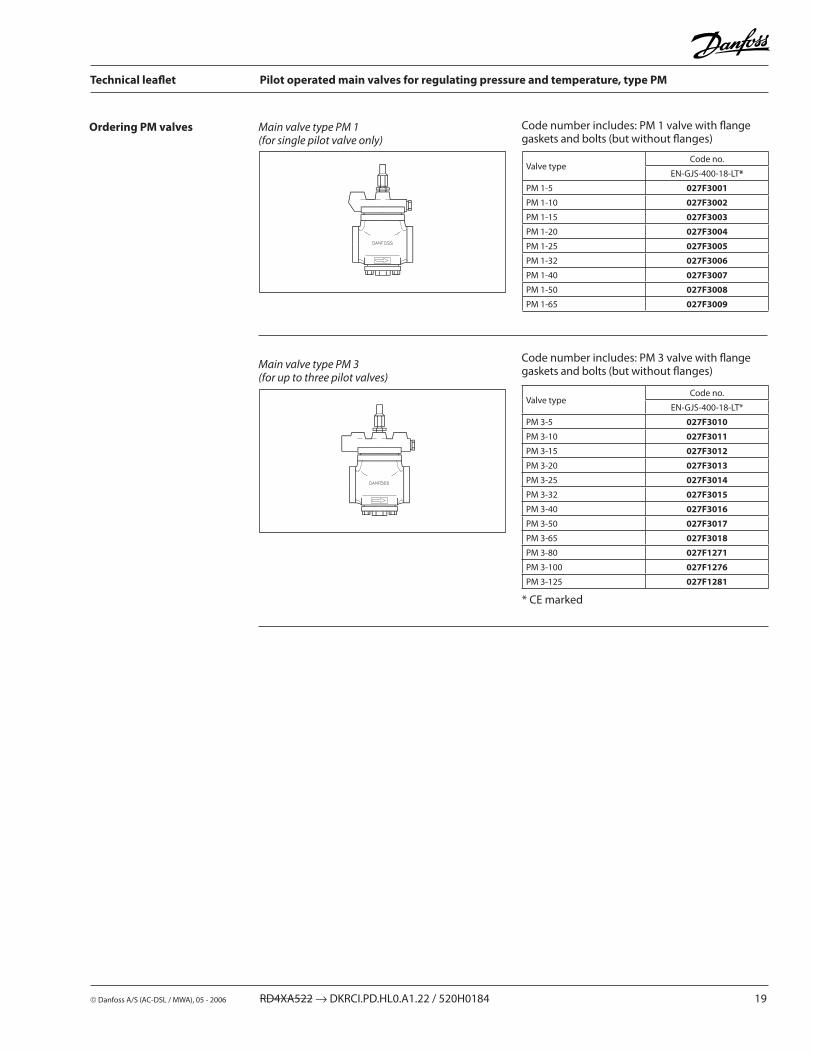
Ordering PM valves Main valve type PM 1 (for single pilot valve only)
Main valve type PM 3 (for up to three pilot valves)
Code number includes: PM 1 valve with flange gaskets and bolts (but without flanges)
Code number includes: PM 3 valve with flange gaskets and bolts (but without flanges)
* CE marked
Valve typeCode no.
EN-GJS-400-18-LT*
PM 1-5 027F3001
PM 1-10 027F3002
PM 1-15 027F3003
PM 1-�0 027F3004
PM 1-�5 027F3005
PM 1-3� 027F3006
PM 1-40 027F3007
PM 1-50 027F3008
PM 1-65 027F3009
Valve typeCode no.
EN-GJS-400-18-LT*
PM 3-5 027F3010
PM 3-10 027F3011
PM 3-15 027F3012
PM 3-�0 027F3013
PM 3-�5 027F3014
PM 3-3� 027F3015
PM 3-40 027F3016
PM 3-50 027F3017
PM 3-65 027F3018
PM 3-80 027F1271
PM 3-100 027F1276
PM 3-1�5 027F1281

�0 RD4XA5�� → DKRCI.PD.HL0.A1.�� / 5�0H0184 Danfoss A/S (AC-DSL / MWA), 05 - �006
Technical leaflet Pilot operated main valves for regulating pressure and temperature, type PM
PM 3PM 1
Dimensions and weights
1) PM valve with flanges but without pilot valves
Valve size H1 H� H3 H4 L L1 L� L3 L4 B1 B� B3 Weight 1) Weight 1)
PM 1 and PM 3 valve body with flanges PM 1 PM 3
PM 5 - �5(DN �0 - �5 - 3�)
mmin.
66�.60
16�6.38
793.11
1013.98
1776.97
1064.17
5��.05
943.70
893.50
75�.95
Oval flange
873.43
6.5 kg.14.3 lb
7 kg.15.4 lb
PM 3�(DN 3� - 40)
mmin.
7��.83
1787.01
963.78
1184.65
�409.45
1706.69
5��.05
943.70
893.50
843.31
8�3.�3
943.70
10.8 kg.�3.8 lb
11.3 kg.�4.9 lb
PM 40(DN 40 - 50)
mmin.
793.11
1877.36
1054.13
1�75.00
�5410.00
1706.69
55�.17
973.8�
9�3.6�
943.70
893.50
10�4.0�
13.7 kg.30.� lb
14 kg.30.9 lb
PM 50(50 - 65)
mmin.
953.74
�058.07
1�34.84
1445.67
�8811.34
�007.87
55�.17
973.8�
9�3.6�
1044.09
1064.17
1134.45
19.5 kg.43.0 lb
19.8 kg.43.7 lb
PM 65(65 - 80)
mmin.
1094.�9
��78.94
1465.75
1676.57
34�13.46
�509.84
60�.36
10�4.0�
973.8�
1�75.00
1134.45
1355.31
�8 kg.61.7 lb
�8.3 kg.6�.4 lb
PM 80(DN 100)
mmin.
15�5.98
36514.37
�148.43
�389.37
43717.�0
3101�.�0
69�.7�
1154.53
1194.69
1907.48
�359.�5
�108.�7
80 kg.176.4 lb
PM 100(DN 1�5)
mmin.
1736.81
39615.59
�469.69
�6910.59
48919.�5
35013.78
833.�7
1�54.9�
1335.�4
��68.90
�7010.63
�439.57
1�0 kg.�64.6 lb
PM 1�5(DN 150)
mmin.
�088.19
45317.83
30111.85
3�51�.80
60��3.70
45517.91
993.90
1515.94
1556.10
�6110.�8
30011.81
�8611.�6
170 kg.374.8 lb

Danfoss A/S (AC-DSL / MWA), 05 - �006 RD4XA5�� → DKRCI.PD.HL0.A1.�� / 5�0H0184 �1
Technical leaflet Pilot operated main valves for regulating pressure and temperature, type PM
AccessoriesPressure gauge connection (weld / solder).
Stainless steel: flanges, bolts for flanges and bolts for top and bottom covers, see flange connections for ordering.
Pressure gauge connection, 1/4 in. flare (self-closing) Must not be used in ammonia plant.
Pressure gauge connection (cutting ring).
Description Code no.
∅ 6.5 mm / ∅ 10 mm (∅ 0.�6 in. / ∅ 0.39 in.) weld / solder
027B2035
Accessories L L1 B1 B� B3 B4 B5
Pressure gauge connection (weld / solder) mmin.
66�.60
54�.13
AF 19 AF �� G 1/4 A G 3/8 A ∅6.5 / ∅10
Description Code no.1/4 in. flare 027B2041
Accessories B B1 B�
Pressure gauge connection, 1/4 in. flare (self-closing)
1/4 in. flaremmin.
G 1/4 A AF 19 1/4 in. flare
Description Code no.
Cutting ring connection, 6 mm Cutting ring connection, 10 mm
027B2063027B2064
Accessories L L1 B B1 B�
Pressure gauge connection (cutting ring)
6 mm mmin.
�71.06
391.54
G 1/4 A AF 19 AF 14
10 mm mmin.
�91.14
401.57
G 1/4 A AF 19 AF 14

�� RD4XA5�� → DKRCI.PD.HL0.A1.�� / 5�0H0184 Danfoss A/S (AC-DSL / MWA), 05 - �006
Technical leaflet Pilot operated main valves for regulating pressure and temperature, type PM
Pressure gauge connection (1/4 FPT).Accessories(continued)
Stainless steel: flanges, bolts for flanges and bolts for top and bottom covers, see flange connections for ordering.
External pilot connection.
Blanking plug for pilot valves.
Description Code no.1/4 FPT 027B2062
Accessories L L1 B B1 B�
Pressure gauge connection
mmin.
�30.91
35.51.40
G 1/4 A AF �� 1/4 FPT
Accessories H H1 OD B B1 B�
External pilot connection
mmin.
903.54
66�.60
180.71
AF 3� AF 3� M �4 × 1.5
PM Description Code no.
5 - 65External pilot connection (incl. damping orifice, D: 1.0 mm)
027F1048
80 - 1�5External pilot connection (incl. damping orifice, D: 1.8 mm)
027F1049
5 - 1�5Accessory bag with seal and O-ring for pilot valve
027F0666
Description Code no.
Blanking plug 027F1046

Danfoss A/S (AC-DSL / MWA), 05 - �006 RD4XA5�� → DKRCI.PD.HL0.A1.�� / 5�0H0184 �3
Technical leaflet Pilot operated main valves for regulating pressure and temperature, type PM
Accessories(continued) Mounting set for:
- PMC + CVC (hot gas bypass) - PM + CVC (max. suction pressure regulation).
The mounting set contains all necessary parts for mounting a CVC pilot valve on a PM main valve.
Mounting set PM + CVPP (HP).
The mounting set contains all necessary parts for mounting a CVP (HP) pilot valve on a PM main valve.
Main valve Pilot valve Code no.
PMC 5 - �5PM 5 - �5
CVC 027F3190
PM 3� CVC 027F3191
PM 40 CVC 027F3192
PM 50 CVC 027F3193
PM 65 CVC 027F3194
Main valve Pilot valve Code no.
PM 5 - �5 CVPP (HP) 027F3195
PM 3� CVPP (HP) 027F3196
PM 40 CVPP (HP) 027F3197
PM 50 CVPP (HP) 027F3198
PM 65 CVPP (HP) 027F3199

�4 RD4XA5�� → DKRCI.PD.HL0.A1.�� / 5�0H0184 Danfoss A/S (AC-DSL / MWA), 05 - �006
Technical leaflet Pilot operated main valves for regulating pressure and temperature, type PM
PumpLocation of valve in system (marked with grey)
Hot gas bypass & defrost line
Discharge line
Wet suction line
Dry suction line
Liquid line without phase change Liquid line with or without phase change
Nominal capacities Liquid line
GravityLocation of valve in system (marked with grey)
Hot gas bypass & defrost line
Discharge line
Wet suction line
Dry suction line
Liquid line without phase change Liquid line with or without phase change
DXLocation of valve in system (marked with grey)
Hot gas bypass & defrost line
Discharge line
Liquid line without phase change
Dry suction line

Danfoss A/S (AC-DSL / MWA), 05 - �006 RD4XA5�� → DKRCI.PD.HL0.A1.�� / 5�0H0184 �5
Technical leaflet Pilot operated main valves for regulating pressure and temperature, type PM
Liquid line
SI units
US units
Calculation example (R 134a capacities):
Running conditions in a plant are as follows: Te = –�0°C Q0 = 300 kW Tliq = 10°C Max. ∆P = 0.3 bar
The capacity table is based on nominal conditions (∆P = 0.� bar, Tliq = 30°C).
The actual capacity must therefore be corrected to a nominal condition by multiplication with correction factors.
Correction factor for ∆P 0.3 bar f∆P = 0.8�.Correction factor for liquid temperature fTliq = 0.8�.
Qn = Qo × f∆P × fTliq = 300 × 0.8� × 0.8� = �0� kW.
From the capacity table a PM �5 with Qn = ��4 kW is the correct selection for the application.
Calculation example (R 134a capacities):
Running conditions in a plant are as follows: Te = –�0°F Qo = 130 TR Tliq = 50°F Max. ∆P = 5 psi
The capacity table is based on nominal conditions (∆P = 3 psi, Tliq = 90°F)
The actual capacity must therefore be corrected to a nominal condition by multiplication with correction factors.
Correction factor for ∆P 5 psi, f∆P = 0.79Correction factor for liquid temperature fTliq = 0.81.
Qn = Qo × f∆P × fTliq = 130 × 0.79 × 0.81 = 83.� TR
From the capacity table a PM 3� with Qn = 91 TR is the correct selection for the application.
Nominal capacities

�6 RD4XA5�� → DKRCI.PD.HL0.A1.�� / 5�0H0184 Danfoss A/S (AC-DSL / MWA), 05 - �006
Technical leaflet Pilot operated main valves for regulating pressure and temperature, type PM
Liquid lineNominal capacities
Capacity table for nominal conditions, QN [kW], Tliq = 30°C, ∆P = 0.� bar
SI units
US units
* �°F below min. operating temperature.
Capacity table for nominal conditions, QN [Tons of Refrigeration], Tliq = 90°F, ∆P = 3 psi
Correction factor for liquid temperature (Tliq)
Liquid temperature
Correction factor
–�0°C 0.8�
–10°C 0.86
0°C 0.88
10°C 0.9�
�0°C 0.96
30°C 1.00
40°C 1.04
50°C 1.09
R 717Type
kv
m3/h
Evaporating temperature Te
–50°C –40°C –30°C –�0°C –10°C 0°C 10°C �0°C
PM 5 1.6 161 164 166 168 170 17� 174 175
PM 10 3 30� 307 311 316 319 3�� 3�5 3�8
PM 15 4 403 410 415 4�1 4�6 430 434 437
PM �0 7 706 717 7�7 736 745 75� 759 765
PM �5 11.5 1159 1177 1194 1�10 1��4 1�36 1�47 1�56
PM 3� 17.� 1734 1761 1786 1809 1830 1849 1865 1879
PM 40 30 30�5 3071 3115 3156 319� 3��5 3�53 3�77
PM 50 43 4335 440� 4465 45�3 4576 46�� 4663 4697
PM 65 79 7965 8088 8�03 8310 8406 849� 8567 86�9
PM 80 141 14�16 14435 14640 14831 15004 15157 15�90 15401
PM 100 �05 �0669 �0987 �1�86 �1563 �1814 ��036 ���31 ��39�
PM 1�5 3�9 33171 3368� 34161 34605 35009 35365 35677 35936
Correction factor for ∆P (f∆P)∆P (bar) Correction factor
0.2 1.00
0.�5 0.89
0.3 0.8�
0.4 0.71
0.5 0.63
0.6 0.58
R 717Type
Cv
USgal/min
Evaporating temperature Te
–60°F* –40°F –�0°F 0°F �0°F 40°F 60°F 80°F
PM 5 1.9 46 47 47 48 48 49 49 49
PM 10 3.5 86 88 89 90 90 91 9� 9�
PM 15 4.6 115 117 118 119 1�1 1�1 1�� 1��
PM �0 8.1 �0� �04 �07 �09 �11 �1� �14 �14
PM �5 13.3 331 336 340 343 347 349 351 35�
PM 3� �0 495 50� 508 514 518 5�� 5�5 5�7
PM 40 35 864 876 886 896 904 911 915 919
PM 50 50 1�38 1�55 1�71 1�84 1�96 1305 131� 1317
PM 65 9� ��75 �306 �334 �359 �381 �398 �411 �419
PM 80 164 4060 4116 4166 4�11 4�49 4�80 4303 4317
PM 100 �38 590� 5984 6057 61�� 6178 6��3 6�56 6�77
PM 1�5 38� 9473 9603 97�1 98�5 9914 9987 10040 10074
Correction factor for ∆P (f∆P)∆P (psi) Correction factor
3 1.00
4 0.87
5 0.79
6 0.7�
7 0.66
8 0.6�
Correction factor for liquid temperature (Tliq)
Liquid temperature
Correction factor
–10°F 0.8�
10°F 0.85
30°F 0.88
50°F 0.9�
70°F 0.96
90°F 1.00
110°F 1.04
130°F 1.09

Danfoss A/S (AC-DSL / MWA), 05 - �006 RD4XA5�� → DKRCI.PD.HL0.A1.�� / 5�0H0184 �7
Technical leaflet Pilot operated main valves for regulating pressure and temperature, type PM
Liquid lineNominal capacities
SI units
US units
Capacity table for nominal conditions, QN [kW], Tliq = 30°C, ∆P = 0.� bar
* �°F below min. operating temperature.
Capacity table for nominal conditions, QN [Tons of Refrigeration], Tliq = 90°F, ∆P = 3 psi
R ��Type
kv
m3/h
Evaporating temperature Te
–50°C –40°C –30°C –�0°C –10°C 0°C 10°C �0°C
PM 5 1.6 3� 33 34 35 36 36 37 38
PM 10 3 59 61 63 65 67 68 70 71
PM 15 4 79 8� 84 87 89 91 93 94
PM �0 7 139 143 147 151 155 159 16� 165
PM �5 11.5 ��8 �35 �4� �49 �55 �61 �66 �71
PM 3� 17.� 341 35� 36� 37� 38� 391 399 406
PM 40 30 594 613 63� 649 666 681 695 708
PM 50 43 85� 879 906 931 954 976 996 1014
PM 65 79 1565 1616 1664 1710 1754 1794 1831 1863
PM 80 141 �794 �883 �970 305� 3130 3�0� 3�67 33�6
PM 100 �05 406� 419� 4319 4437 4550 4655 4750 4835
PM 1�5 3�9 6519 67�8 6931 71�0 7303 7471 76�3 7760
Correction factor for ∆P (f∆P)∆P (bar) Correction factor
0.2 1.00
0.�5 0.89
0.3 0.8�
0.4 0.71
0.5 0.63
0.6 0.58
Correction factor for liquid temperature (Tliq)
Liquid temperature
Correction factor
–�0°C 0.71
–10°C 0.75
0°C 0.80
10°C 0.86
�0°C 0.9�
30°C 1.00
40°C 1.09
50°C 1.��
R ��Type
Cv
USgal/min
Evaporating temperature Te
–60°F* –40°F –�0°F 0°F �0°F 40°F 60°F 80°F
PM 5 1.9 9 9 10 10 10 10 11 11
PM 10 3.5 17 17 18 18 19 19 �0 �0
PM 15 4.6 �� �3 �4 �5 �5 �6 �7 �7
PM �0 8.1 39 41 4� 43 44 45 47 47
PM �5 13.3 64 67 69 71 73 75 76 78
PM 3� �0 96 100 103 106 109 11� 114 116
PM 40 35 168 174 179 185 190 195 199 �03
PM 50 50 �40 �49 �57 �65 �7� �79 �86 �91
PM 65 9� 441 457 473 487 501 513 5�5 534
PM 80 164 788 816 843 869 893 916 937 954
PM 100 �38 1146 1187 1��6 1�64 1�99 1331 136� 1387
PM 1�5 38� 1838 1904 1968 �0�8 �084 �136 �187 ���6
Correction factor for ∆P (f∆P)∆P (psi) Correction factor
3 1.00
4 0.87
5 0.79
6 0.7�
7 0.66
8 0.6�
Correction factor for liquid temperature (Tliq)
Liquid temperature
Correction factor
–10°F 0.73
10°F 0.77
30°F 0.8�
50°F 0.87
70°F 0.93
90°F 1.00
110°F 1.09
130°F 1.�0

�8 RD4XA5�� → DKRCI.PD.HL0.A1.�� / 5�0H0184 Danfoss A/S (AC-DSL / MWA), 05 - �006
Technical leaflet Pilot operated main valves for regulating pressure and temperature, type PM
Nominal capacities Liquid line
SI units
US units
* �°F below min. operating temperature.
Capacity table for nominal conditions, QN [kW], Tliq = 30°C, ∆P = 0.� bar
Capacity table for nominal conditions, QN [Tons of Refrigeration], Tliq = 90°F, ∆P = 3 psi
R 134aType
kv
m3/h
Evaporating temperature Te
–50°C –40°C –30°C –�0°C –10°C 0°C 10°C �0°C
PM 5 1.6 - �8 30 31 3� 34 35 36
PM 10 3 - 53 56 58 61 63 66 68
PM 15 4 - 71 75 78 81 84 87 90
PM �0 7 - 1�5 130 136 14� 148 153 158
PM �5 11.5 - �05 �14 ��4 �33 �43 �51 �60
PM 3� 17.� - 306 3�1 335 349 363 376 389
PM 40 30 - 534 559 584 609 633 656 678
PM 50 43 - 765 801 837 87� 907 940 97�
PM 65 79 - 1406 147� 1539 1603 1666 17�7 1785
PM 80 141 - �509 �6�8 �746 �861 �973 308� 3186
PM 100 �05 - 3648 38�1 3993 4159 43�3 4481 463�
PM 1�5 3�9 - 5855 6131 6408 6675 6938 719� 7434
Correction factor for ∆P (f∆P)∆P (bar) Correction factor
0.2 1.00
0.�5 0.89
0.3 0.8�
0.4 0.71
0.5 0.63
0.6 0.58
Correction factor for liquid temperature (Tliq)
Liquid temperature
Correction factor
–�0°C 0.66
–10°C 0.70
0°C 0.76
10°C 0.8�
�0°C 0.90
30°C 1.00
40°C 1.13
50°C 1.�9
R 134aType
Cv
USgal/min
Evaporating temperature Te
–60°F* –40°F –�0°F -°F �0°F 40°F 60°F 80°F
PM 5 1.9 - 8 8 9 9 10 10 10
PM 10 3.5 - 15 16 17 17 18 19 �0
PM 15 4.6 - �0 �1 �� �3 �4 �5 �6
PM �0 8.1 - 35 37 39 41 4� 44 46
PM �5 13.3 - 58 61 64 67 70 73 75
PM 3� �0 - 86 91 95 100 104 109 11�
PM 40 35 - 150 158 166 174 181 189 196
PM 50 50 - �15 ��7 �38 �49 �60 �71 �81
PM 65 9� - 396 417 438 458 478 499 516
PM 80 164 - 707 744 78� 818 853 890 9�1
PM 100 �38 - 10�7 108� 1136 1189 1�40 1�94 1340
PM 1�5 38� - 1649 1737 18�4 1908 1990 �076 �150
Correction factor for ∆P (f∆P)∆P (psi) Correction factor
3 1.00
4 0.87
5 0.79
6 0.7�
7 0.66
8 0.6�
Correction factor for liquid temperature (Tliq)
Liquid temperature
Correction factor
–10°F 0.64
10°F 0.68
30°F 0.74
50°F 0.81
70°F 0.89
90°F 1.00
110°F 1.15
130°F 1.35

Danfoss A/S (AC-DSL / MWA), 05 - �006 RD4XA5�� → DKRCI.PD.HL0.A1.�� / 5�0H0184 �9
Technical leaflet Pilot operated main valves for regulating pressure and temperature, type PM
Nominal capacities
SI units
US units
Liquid line
Capacity table for nominal conditions, QN [kW], Tliq = 30°C, ∆P = 0.� bar
* �°F below min. operating temperature.
Capacity table for nominal conditions, QN [Tons of Refrigeration], Tliq = 90°F, ∆P = 3 psi
R 404AType
kv
m3/h
Evaporating temperature Te
–50°C –40°C –30°C –�0°C –10°C 0°C 10°C �0°C
PM 5 1.6 17.8 19.1 �0 �� �3 �4 �5 �6
PM 10 3 33 36 38 40 43 45 47 48
PM 15 4 45 48 51 54 57 60 6� 64
PM �0 7 78 83 89 94 99 104 109 113
PM �5 11.5 1�8 137 146 155 163 171 179 185
PM 3� 17.� 19� �05 �19 �3� �44 �56 �67 �77
PM 40 30 334 358 381 404 4�6 447 466 483
PM 50 43 479 513 546 579 611 641 668 693
PM 65 79 880 94� 1004 1064 11�� 1177 1��8 1�73
PM 80 141 1570 1681 179� 1899 �00� �100 �191 ��7�
PM 100 �05 ��83 �445 �605 �761 �911 3054 3185 3303
PM 1�5 3�9 3663 39�3 4181 4431 467� 4901 511� 5300
Correction factor for ∆P (f∆P)∆P (bar) Correction factor
0.2 1.00
0.�5 0.89
0.3 0.8�
0.4 0.71
0.5 0.63
0.6 0.58
Correction factor for liquid temperature (Tliq)
Liquidtemperature
Correction factor
–�0°C 0.55
–10°C 0.60
0°C 0.66
10°C 0.74
�0°C 0.85
30°C 1.00
40°C 1.�3
50°C 1.68
R 404AType
Cv
USgal/min
Evaporating temperature Te
–60°F* –40°F –�0°F 0°F �0°F 40°F 60°F 80°F
PM 5 1.9 4.9 5.3 5.7 6.1 6.4 6.8 7.1 7.4
PM 10 3.5 9.� 9.9 10.6 11.4 1�.1 1�.7 13.3 13.8
PM 15 4.6 1�.� 13.� 14.� 15.� 16.1 16.9 17.8 18.4
PM �0 8.1 �1 �3 �5 �7 �8 30 31 3�
PM �5 13.3 35 38 41 44 46 49 51 53
PM 3� �0 53 57 61 65 69 73 76 79
PM 40 35 9� 99 106 114 1�1 1�7 133 138
PM 50 50 131 14� 153 163 173 18� 191 198
PM 65 9� �41 �61 �80 �99 317 334 351 364
PM 80 164 431 466 501 534 567 597 6�6 649
PM 100 �38 6�6 677 7�8 777 8�4 868 911 944
PM 1�5 38� 1005 1087 1168 1�47 13�� 139� 1461 1515
Correction factor for ∆P (f∆P)∆P (psi) Correction factor
3 1.00
4 0.87
5 0.79
6 0.7�
7 0.66
8 0.6�
Correction factor for liquid temperature (Tliq)
Liquid temperature
Correction factor
–10°F 0.5�
10°F 0.57
30°F 0.63
50°F 0.7�
70°F 0.83
90°F 1.00
110°F 1.�9
130°F 1.9�

30 RD4XA5�� → DKRCI.PD.HL0.A1.�� / 5�0H0184 Danfoss A/S (AC-DSL / MWA), 05 - �006
Technical leaflet Pilot operated main valves for regulating pressure and temperature, type PM
Nominal capacities
PumpLocation of valve in system (marked with grey)
Hot gas bypass & defrost line
Discharge line
Wet suction line
Dry suction line
Liquid line without phase change Liquid line with or without phase change
SI units
US units
Calculation example (R 717 capacities):
Running conditions in a plant are as follows:
Te = –�0°C Q0 = 180 kW circulation rate = 3 Max. ∆P = 0.3 bar
The capacity table is based on nominal conditions (pressure drop ∆P = 0.3 bar, circulation rate = 4).
The actual capacity must therefore be corrected to a nominal condition by multiplication with correction factors.
Correction factor for ∆P 0.3 bar f∆P = 0.8�Correction factor for circulation rate frec = 0.75.
Qn = Q0 × f∆p × frec = 180 × 0.8� × 0.75 = 111 kW
From the capacity table a PM 15 with Qn = 133 kW is the correct selection for the application.
Calculation example (R 717 capacities):
Running conditions in a plant are as follows:
Te = –�0°F Q0 = 130 TR Circulation rate = 3 Max. ∆P = 5 psi
The capacity table is based on nominal conditions (pressure drop ∆p = 3 psi, circulation rate = 4).
The actual capacity must therefore be corrected to a nominal condition by multiplication with correction factors.
Correction factor for ∆P 5 psi f∆p = 0.79Correction factor for circulation rate frec = 0.75.
Qn = Q0 x f∆P x fcirc = 140 × 0.79 × 0.75 = 83 TR
From the capacity table a PM �5 with Qn = 114 TR is the correct selection for the application.
Pumped liquid line

Danfoss A/S (AC-DSL / MWA), 05 - �006 RD4XA5�� → DKRCI.PD.HL0.A1.�� / 5�0H0184 31
Technical leaflet Pilot operated main valves for regulating pressure and temperature, type PM
Nominal capacities
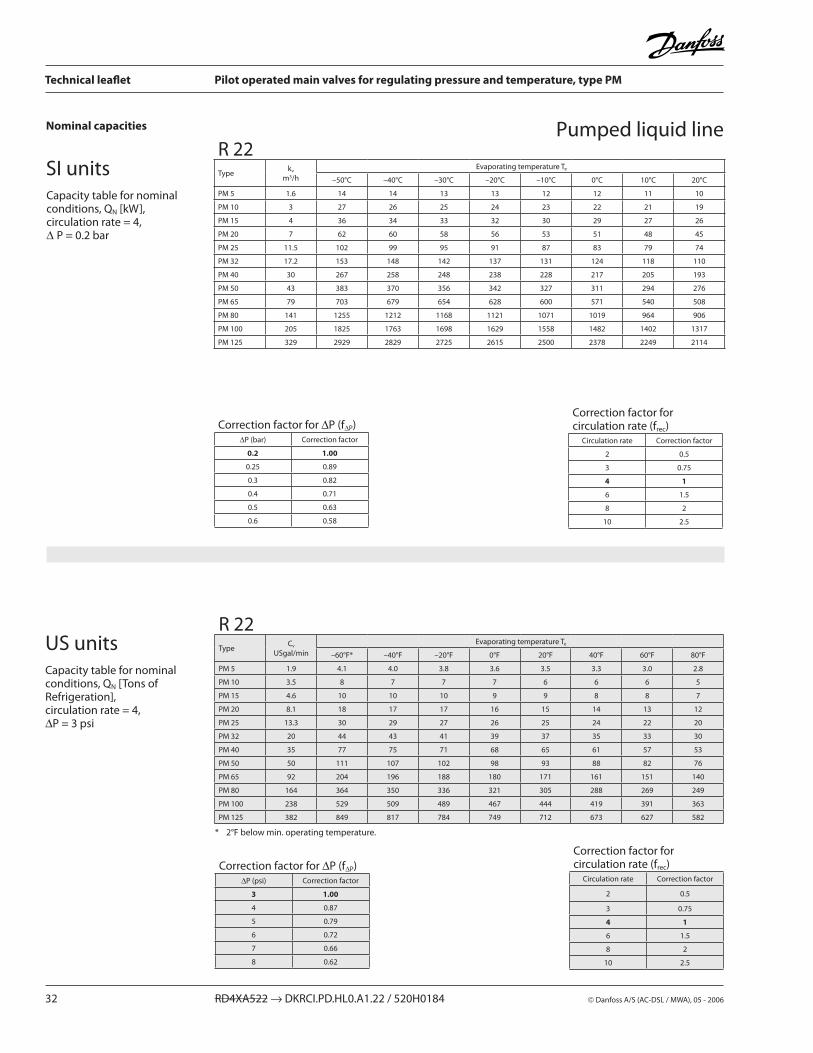
Capacity table for nominal conditions, QN [kW], circulation rate = 4,∆P = 0.� bar
SI units
US units
* �°F below min. operating temperature.
Capacity table for nominal conditions, QN [Tons of Refrigeration], circulation rate = 4,∆P = 3 psi
Pumped liquid lineR 717Type
kv
m3/h
Evaporating temperature Te
–50°C –40°C –30°C –�0°C –10°C 0°C 10°C �0°C
PM 5 1.6 58 57 55 53 51 50 48 46
PM 10 3 109 106 103 100 96 93 89 85
PM 15 4 146 14� 137 133 1�9 1�4 119 114
PM �0 7 �55 �48 �41 �33 ��5 �17 �08 199
PM �5 11.5 4�0 407 395 383 370 356 34� 3�8
PM 3� 17.� 6�8 609 591 57� 553 533 51� 490
PM 40 30 1095 1063 1031 998 964 9�9 893 855
PM 50 43 1569 15�3 1478 1431 138� 133� 1�80 1��5
PM 65 79 �883 �798 �715 �6�9 �539 �448 �351 ��51
PM 80 141 5146 4994 4847 4691 453� 4369 4197 4017
PM 100 �05 748� 7�61 7046 68�1 6589 6351 610� 5841
PM 1�5 3�9 1�007 11654 11309 10947 10575 10193 9793 9374
Correction factor for ∆P (f∆P)∆P (bar) Correction factor
0.2 1.00
0.�5 0.89
0.3 0.8�
0.4 0.71
0.5 0.63
0.6 0.58
Correction factor for circulation rate (frec)
Circulation rate Correction factor
� 0.5
3 0.75
4 1
6 1.5
8 �
10 �.5
R 717Type
Cv
USgal/min
Evaporating temperature Te
–60°F* –40°F –�0°F 0°F �0°F 40°F 60°F 80°F
PM 5 1.9 16.9 16.4 15.9 15.3 14.7 14.1 13.4 1�.8
PM 10 3.5 3� 31 30 �9 �8 �6 �5 �4
PM 15 4.6 4� 41 40 38 37 35 34 3�
PM �0 8.1 74 7� 69 67 64 6� 59 56
PM �5 13.3 1�1 118 114 110 106 101 96 9�
PM 3� �0 18� 176 170 165 158 15� 144 137
PM 40 35 317 307 �97 �87 �76 �64 �51 �39
PM 50 50 454 440 4�6 411 395 379 360 343
PM 65 9� 834 809 783 756 7�6 696 66� 630
PM 80 164 1489 1443 1397 1349 1�95 1�4� 118� 11�4
PM 100 �38 �165 �098 �031 1961 1883 1806 1718 1634
PM 1�5 38� 3474 3367 3�60 3148 30�� �898 �757 �6�3
Correction factor for ∆P (f∆P)∆P (psi) Correction factor
3 1.00
4 0.87
5 0.79
6 0.7�
7 0.66
8 0.6�
Correction factor for circulation rate (frec)
Circulation rate Correction factor
� 0.5
3 0.75
4 1
6 1.5
8 �
10 �.5
3� RD4XA5�� → DKRCI.PD.HL0.A1.�� / 5�0H0184 Danfoss A/S (AC-DSL / MWA), 05 - �006
Technical leaflet Pilot operated main valves for regulating pressure and temperature, type PM
Nominal capacities
SI units
US units
Capacity table for nominal conditions, QN [kW], circulation rate = 4, ∆P = 0.� bar
R ��Type
kv
m3/h
Evaporating temperature Te
–50°C –40°C –30°C –�0°C –10°C 0°C 10°C �0°C
PM 5 1.6 14 14 13 13 1� 1� 11 10
PM 10 3 �7 �6 �5 �4 �3 �� �1 19
PM 15 4 36 34 33 3� 30 �9 �7 �6
PM �0 7 6� 60 58 56 53 51 48 45
PM �5 11.5 10� 99 95 91 87 83 79 74
PM 3� 17.� 153 148 14� 137 131 1�4 118 110
PM 40 30 �67 �58 �48 �38 ��8 �17 �05 193
PM 50 43 383 370 356 34� 3�7 311 �94 �76
PM 65 79 703 679 654 6�8 600 571 540 508
PM 80 141 1�55 1�1� 1168 11�1 1071 1019 964 906
PM 100 �05 18�5 1763 1698 16�9 1558 148� 140� 1317
PM 1�5 3�9 �9�9 �8�9 �7�5 �615 �500 �378 ��49 �114
* �°F below min. operating temperature.
Capacity table for nominal conditions, QN [Tons of Refrigeration], circulation rate = 4, ∆P = 3 psi
Pumped liquid line
Correction factor for ∆P (f∆P)∆P (bar) Correction factor
0.2 1.00
0.�5 0.89
0.3 0.8�
0.4 0.71
0.5 0.63
0.6 0.58
Correction factor for circulation rate (frec)
Circulation rate Correction factor
� 0.5
3 0.75
4 1
6 1.5
8 �
10 �.5
Correction factor for ∆P (f∆P)∆P (psi) Correction factor
3 1.00
4 0.87
5 0.79
6 0.7�
7 0.66
8 0.6�
Correction factor for circulation rate (frec)
Circulation rate Correction factor
� 0.5
3 0.75
4 1
6 1.5
8 �
10 �.5
R ��Type
Cv
USgal/min
Evaporating temperature Te
–60°F* –40°F –�0°F 0°F �0°F 40°F 60°F 80°F
PM 5 1.9 4.1 4.0 3.8 3.6 3.5 3.3 3.0 �.8
PM 10 3.5 8 7 7 7 6 6 6 5
PM 15 4.6 10 10 10 9 9 8 8 7
PM �0 8.1 18 17 17 16 15 14 13 1�
PM �5 13.3 30 �9 �7 �6 �5 �4 �� �0
PM 3� �0 44 43 41 39 37 35 33 30
PM 40 35 77 75 71 68 65 61 57 53
PM 50 50 111 107 10� 98 93 88 8� 76
PM 65 9� �04 196 188 180 171 161 151 140
PM 80 164 364 350 336 3�1 305 �88 �69 �49
PM 100 �38 5�9 509 489 467 444 419 391 363
PM 1�5 38� 849 817 784 749 71� 673 6�7 58�

Danfoss A/S (AC-DSL / MWA), 05 - �006 RD4XA5�� → DKRCI.PD.HL0.A1.�� / 5�0H0184 33
Technical leaflet Pilot operated main valves for regulating pressure and temperature, type PM
Nominal capacities
SI units
US units
* �°F below min. operating temperature.
Pumped liquid line
Capacity table for nominal conditions, QN [kW], circulation rate = 4, ∆P = 0.� bar
Capacity table for nominal conditions, QN [Tons of Refrigeration], circulation rate = 4, ∆P = 3 psi
R 404AType
kv
m3/h
Evaporating temperature Te
–50°C –40°C –30°C –�0°C –10°C 0°C 10°C �0°C
PM 5 1.6 1� 11 11 10 9 9 8 7
PM 10 3 �� �1 �0 19 18 17 15 14
PM 15 4 �9 �8 �6 �5 �4 �� �0 19
PM �0 7 51 49 46 44 41 39 36 33
PM �5 11.5 83 80 75 7� 68 64 59 54
PM 3� 17.� 1�5 1�0 113 108 10� 95 88 80
PM 40 30 �17 �08 197 188 177 166 154 140
PM 50 43 311 �99 �8� �69 �54 �38 ��0 �00
PM 65 79 57� 549 519 495 467 437 405 368
PM 80 141 10�1 980 9�6 883 834 781 7�� 657
PM 100 �05 1484 14�4 1346 1�84 1�13 1135 1050 956
PM 1�5 3�9 �38� ��86 �160 �061 1947 18�� 1685 1534
Correction factor for ∆P (f∆P)∆P (bar) Correction factor
0.2 1.00
0.�5 0.89
0.3 0.8�
0.4 0.71
0.5 0.63
0.6 0.58
Correction factor for circulation rate (frec)
Circulation rate Correction factor
� 0.5
3 0.75
4 1
6 1.5
8 �
10 �.5
R 404AType
Cv
USgal/min
Evaporating temperature Te
–60°F* –40°F –�0°F 0°F �0°F 40°F 60°F 80°F
PM 5 1.9 3.4 3.� 3.0 �.9 �.7 �.5 �.� �.0
PM 10 3.5 6 6 6 5 5 5 4 4
PM 15 4.6 8 8 8 7 7 6 6 5
PM �0 8.1 15 14 13 13 1� 11 10 9
PM �5 13.3 �4 �3 �� �1 19 18 16 14
PM 3� �0 36 35 33 31 �9 �7 �4 �1
PM 40 35 63 60 57 54 50 47 4� 37
PM 50 50 90 86 81 77 7� 67 60 54
PM 65 9� 166 159 150 141 133 1�3 111 98
PM 80 164 �96 �83 �67 �5� �37 �19 198 176
PM 100 �38 431 41� 388 367 344 318 �87 �55
PM 1�5 38� 691 661 6�3 589 55� 511 461 410
Correction factor for ∆P (f∆P)∆P (psi) Correction factor
3 1.00
4 0.87
5 0.79
6 0.7�
7 0.66
8 0.6�
Correction factor for circulation rate (frec)
Circulation rate Correction factor
� 0.5
3 0.75
4 1
6 1.5
8 �
10 �.5

34 RD4XA5�� → DKRCI.PD.HL0.A1.�� / 5�0H0184 Danfoss A/S (AC-DSL / MWA), 05 - �006
Technical leaflet Pilot operated main valves for regulating pressure and temperature, type PM
Nominal capacities Wet suction line
PumpLocation of valve in system (marked with grey)
Hot gas bypass & defrost line
Discharge line
Wet suction line
Dry suction line
Liquid line without phase change Liquid line with or without phase change
GravityLocation of valve in system (marked with grey)
Hot gas bypass & defrost line
Discharge line
Wet suction line
Dry suction line
Liquid line without phase change Liquid line with or without phase change

Danfoss A/S (AC-DSL / MWA), 05 - �006 RD4XA5�� → DKRCI.PD.HL0.A1.�� / 5�0H0184 35
Technical leaflet Pilot operated main valves for regulating pressure and temperature, type PM
Nominal capacities Wet suction line
SI units
US units
Calculation example (R 717 capacities):
Running conditions in a plant are as follows:
Te = –�0°C Q0 = 100 kW Circulation rate = 3 Max. ∆P = 0.3 bar
The capacity table is based on nominal conditions (pressure drop ∆P = 0.� bar, circulation rate = 4).
The actual capacity must therefore be corrected to a nominal condition by multiplication with correction factors.
Correction factor for ∆P 0.3 bar f∆P = 0.8�Correction factor for circulation rate frec = 0.9.
Qn = Q0 × f∆P × frec = 100 × 0.8� × 0.9 = 73,8 kW.
From the capacity table a PM 40 with Qn = 107 kW is the correct selection for the application.
Calculation example (R 717 capacities):
Running conditions in a plant are as follows:
Te = – �0°F Q0 = 10 TR Circulation rate = 3 Max. ∆P = 5 psi
The capacity table is based on nominal conditions (pressure drop ∆P = 3 psi, circulation rate = 4).
The actual capacity must therefore be corrected to a nominal condition by multiplication with correction factors.
Correction factor for ∆P 5 psi f∆p = 0.79Correction factor for circulation rate frec = 0.9.
Qn = Q0 × f∆P × fcirc = 10 × 0.79 × 0.9 = 7.1 TR
From the capacity table a PM �5 with Qn = 10.0 TR is the correct selection for the application.

36 RD4XA5�� → DKRCI.PD.HL0.A1.�� / 5�0H0184 Danfoss A/S (AC-DSL / MWA), 05 - �006
Technical leaflet Pilot operated main valves for regulating pressure and temperature, type PM
Nominal capacities Wet suction line
SI units
US units
Capacity table for nominal conditions, QN [kW], circulation rate = 4, ∆P = 0.� bar
* �°F below min. operating temperature.
Capacity table for nominal conditions, QN [Tons of Refrigeration], circulation rate = 4, ∆P = 3 psi
R 717Type
kv
m3/h
Evaporating temperature Te
–50°C –40°C –30°C –�0°C –10°C 0°C 10°C �0°C
PM 5 1.6 �.9 3.8 4.7 5.7 6.8 8.0 9.� 10.4
PM 10 3 5.5 7.1 8.8 10.7 1�.8 15.0 17.� 19.6
PM 15 4 7.3 9.5 11.8 14.3 17.0 19.9 �3.0 �6.1
PM �0 7 1�.8 16.6 �0.6 �5.0 �9.8 34.9 40 46
PM �5 11.5 �1.0 �7.� 33.8 41 49 57 66 75
PM 3� 17.� 31.4 41 51 61 73 86 99 11�
PM 40 30 55 71 88 107 1�8 150 17� 196
PM 50 43 79 10� 1�6 154 183 �14 �47 �81
PM 65 79 144 187 �3� �8� 336 394 454 516
PM 80 141 �58 334 415 504 600 703 810 9�0
PM 100 �05 375 485 603 733 873 10�� 1177 1338
PM 1�5 3�9 601 779 968 1176 1401 1640 1890 �147
Correction factor for ∆P (f∆P)∆P (bar) Correction factor
0.2 1.00
0.�5 0.89
0.3 0.8�
0.4 0.71
0.5 0.63
0.6 0.58
Correction factor for circulation rate (frec)
Circulation rate Correction factor
� 0.77
3 0.90
4 1
6 1.13
8 1.�0
10 1.�5
R 717Type
Cv
USgal/min
Evaporating temperature Te
–60°F* –40°F –�0°F 0°F �0°F 40°F 60°F 80°F
PM 5 1.9 0.8 1.1 1.4 1.7 �.1 �.5 �.8 3.�
PM 10 3.5 1.5 �.1 �.6 3.� 3.9 4.6 5.3 6.1
PM 15 4.6 �.0 �.7 3.5 4.3 5.� 6.� 7.1 8.1
PM �0 8.1 3.6 4.8 6.1 7.6 9.1 10.8 1�.4 14.�
PM �5 13.3 5.9 7.9 10.0 1�.4 15.0 17.7 �0 �3
PM 3� �0 8.8 11.8 14.9 18.6 �� �6 31 35
PM 40 35 15.3 �1 �6 3� 39 46 53 61
PM 50 50 �� �9 37 46 56 66 76 87
PM 65 9� 40 54 69 85 103 1�� 140 160
PM 80 164 7� 96 1�� 15� 184 �17 �51 �86
PM 100 �38 104 140 178 ��1 �67 315 365 415
PM 1�5 38� 168 ��5 �85 355 4�8 506 585 666
Correction factor for ∆P (f∆P)∆P (psi) Correction factor
3 1.00
4 0.87
5 0.79
6 0.7�
7 0.66
8 0.6�
Correction factor for circulation rate (frec)
Circulation rate Correction factor
� 0.77
3 0.90
4 1
6 1.13
8 1.�0
10 1.�5

Danfoss A/S (AC-DSL / MWA), 05 - �006 RD4XA5�� → DKRCI.PD.HL0.A1.�� / 5�0H0184 37
Technical leaflet Pilot operated main valves for regulating pressure and temperature, type PM
Nominal capacities
SI units
US units
Capacity table for nominal conditions, QN [kW], circulation rate = 4,∆P = 0.� bar
* �°F below min. operating temperature.
Capacity table for nominal conditions, QN [Tons of Refrigeration], circulation rate = 4,∆P = 3 psi
Wet suction lineR ��Type
kv
m3/h
Evaporating temperature Te
–50°C –40°C –30°C –�0°C –10°C 0°C 10°C �0°C
PM 5 1.6 1.4 1.7 �.1 �.5 �.8 3.� 3.6 4.0
PM 10 3 �.7 3.3 3.9 4.6 5.3 6.0 6.7 7.4
PM 15 4 3.6 4.4 5.� 6.1 7.1 8.0 9.0 9.9
PM �0 7 6.� 7.6 9.� 10.8 1�.4 14.1 16 17
PM �5 11.5 10.3 1�.6 15.1 18 �0 �3 �6 �8
PM 3� 17.� 15.3 19 �3 �6 30 35 39 43
PM 40 30 �7 33 39 46 53 60 67 74
PM 50 43 38 47 56 66 76 86 97 106
PM 65 79 70 86 103 1�1 140 159 177 196
PM 80 141 1�6 154 185 �17 �50 �83 317 349
PM 100 �05 183 ��4 �68 315 363 41� 460 507
PM 1�5 3�9 �93 359 431 505 583 661 739 814
Correction factor for ∆P (f∆P)∆P (bar) Correction factor
0.2 1.00
0.�5 0.89
0.3 0.8�
0.4 0.71
0.5 0.63
0.6 0.58
Correction factor for circulation rate (frec)
Circulation rate Correction factor
� 0.77
3 0.90
4 1
6 1.13
8 1.�0
10 1.�5
R ��Type
Cv
USgal/min
Evaporating temperature Te
–60°F* –40°F –�0°F 0°F �0°F 40°F 60°F 80°F
PM 5 1.9 0.4 0.5 0.6 0.7 0.9 1.0 1.1 1.�
PM 10 3.5 0.8 0.9 1.� 1.4 1.6 1.8 �.1 �.3
PM 15 4.6 1.0 1.3 1.5 1.8 �.1 �.4 �.8 3.0
PM �0 8.1 1.8 �.� �.7 3.� 3.7 4.3 4.8 5.3
PM �5 13.3 �.9 3.6 4.4 5.3 6.1 7.0 8 9
PM 3� �0 4.3 5.4 6.6 7.9 9 10 1� 13
PM 40 35 7.6 9 1� 14 16 18 �1 �3
PM 50 50 11 14 17 �0 �3 �6 30 33
PM 65 9� �0 �5 30 36 4� 48 54 60
PM 80 164 35 45 54 65 75 86 97 107
PM 100 �38 5� 65 79 94 109 1�5 141 156
PM 1�5 38� 83 104 1�7 151 175 �00 ��7 �50
Correction factor for ∆P (f∆P)∆P (psi) Correction factor
3 1.00
4 0.87
5 0.79
6 0.7�
7 0.66
8 0.6�
Correction factor for circulation rate (frec)
Circulation rate Correction factor
� 0.77
3 0.90
4 1
6 1.13
8 1.�0
10 1.�5

38 RD4XA5�� → DKRCI.PD.HL0.A1.�� / 5�0H0184 Danfoss A/S (AC-DSL / MWA), 05 - �006
Technical leaflet Pilot operated main valves for regulating pressure and temperature, type PM
Nominal capacities
SI units
US units
Capacity table for nominal conditions, QN [kW], circulation rate = 4,∆P = 0.� bar
* �°F below min. operating temperature.
Capacity table for nominal conditions, QN [Tons of Refrigeration], circulation rate = 4,∆P = 3 psi
Wet suction lineR 404AType
kv
m3/h
Evaporating temperature Te
–50°C –40°C –30°C –�0°C –10°C 0°C 10°C �0°C
PM 5 1.6 1.5 1.8 �.1 �.5 �.8 3.1 3.5 3.8
PM 10 3 �.8 3.4 3.9 4.6 5.3 5.9 6.5 7.1
PM 15 4 3.7 4.5 5.3 6.1 7.0 7.9 8.7 9.4
PM �0 7 6.5 7.8 9.� 10.7 1�.3 13.8 15 16
PM �5 11.5 10.6 1�.9 15.1 18 �0 �3 �5 �7
PM 3� 17.� 15.9 19 �3 �6 30 34 37 41
PM 40 30 �8 34 39 46 53 59 65 71
PM 50 43 40 48 56 66 75 85 93 101
PM 65 79 73 88 104 1�1 138 155 17� 186
PM 80 141 130 158 185 �16 �47 �77 306 33�
PM 100 �05 189 ��9 �69 314 359 403 445 483
PM 1�5 3�9 304 368 43� 504 576 647 715 775
Correction factor for ∆P (f∆P)∆P (bar) Correction factor
0.2 1.00
0.�5 0.89
0.3 0.8�
0.4 0.71
0.5 0.63
0.6 0.58
Correction factor for circulation rate (frec)
Circulation rate Correction factor
� 0.77
3 0.90
4 1
6 1.13
8 1.�0
10 1.�5
R 404AType
Cv
USgal/min
Evaporating temperature Te
–60°F* –40°F –�0°F 0°F �0°F 40°F 60°F 80°F
PM 5 1.9 0.4 0.5 0.6 0.7 0.8 0.9 1.1 1.1
PM 10 3.5 0.8 1.0 1.� 1.4 1.6 1.8 �.0 �.1
PM 15 4.6 1.0 1.3 1.5 1.8 �.1 �.4 �.6 �.8
PM �0 8.1 1.8 �.3 �.7 3.� 3.7 4.1 4.6 5.0
PM �5 13.3 3.0 3.7 4.4 5.� 6.0 6.8 8 8
PM 3� �0 4.5 5.6 6.6 7.8 9 10 11 1�
PM 40 35 7.8 10 1� 14 16 18 �0 �1
PM 50 50 11 14 17 �0 �3 �5 �8 31
PM 65 9� �1 �6 31 36 41 47 5� 56
PM 80 164 37 46 55 64 74 84 93 100
PM 100 �38 54 66 79 93 108 1�1 135 146
PM 1�5 38� 86 106 1�7 150 173 195 �17 �34
Correction factor for ∆P (f∆P)∆P (psi) Correction factor
3 1.00
4 0.87
5 0.79
6 0.7�
7 0.66
8 0.6�
Correction factor for circulation rate (frec)
Circulation rate Correction factor
� 0.77
3 0.90
4 1
6 1.13
8 1.�0
10 1.�5

Danfoss A/S (AC-DSL / MWA), 05 - �006 RD4XA5�� → DKRCI.PD.HL0.A1.�� / 5�0H0184 39
Technical leaflet Pilot operated main valves for regulating pressure and temperature, type PM
Nominal capacities Dry suction line
PumpLocation of valve in system (marked with grey)
Hot gas bypass & defrost line
Discharge line
Wet suction line
Dry suction line
Liquid line without phase change Liquid line with or without phase change
GravityLocation of valve in system (marked with grey)
Hot gas bypass & defrost line
Discharge line
Wet suction line
Liquid line without phase change Liquid line with or without phase change
DXLocation of valve in system (marked with grey)
Hot gas bypass & defrost line
Discharge line
Liquid line with or without phase change
Dry suction line

40 RD4XA5�� → DKRCI.PD.HL0.A1.�� / 5�0H0184 Danfoss A/S (AC-DSL / MWA), 05 - �006
Technical leaflet Pilot operated main valves for regulating pressure and temperature, type PM
Nominal capacities Dry suction line
SI units
US units
Calculation example (R 134a capacities):
Running conditions in a plant are as follows:
Te = –�0°C Q0 = 90 kW Tliq = 10°C Ts = 6°C Max. ∆P = 0.3 bar
The capacity table is based on nominal conditions (pressure drop ∆P = 0.� bar, Tliq = 30°C).
The actual capacity must therefore be corrected to a nominal condition by multiplication with correction factors.
Correction factor for ∆P 0.3 bar f∆P = 0.8�Correction factor for liquid temperature fTliq = 0.8�Correction factor for superheat (TS) = 1,0
Qn = Q0 × f∆P × fTliq × fTs = 90 × 0.8� × 0.8� × 1.0 = 60.5 kW
From the capacity table a PM 50 with Qn = 64 kW is the correct selection for the application.
Calculation example (R 134a capacities):
Running conditions in a plant are as follows:
Te = 0°F Q0 = �3 TR Tliq = 50°F Ts = 10°F Max. ∆P = 5 psi
The capacity table is based on nominal conditions (pressure drop ∆P = 3 psi, Tliq = 90°F)
The actual capacity must therefore be corrected to a nominal condition by multiplication with correction factors.
Correction factor for ∆P 5 psi f∆p = 0.79Correction factor for liquid temperature fTliq = 0.81Correction factor for superheat (TS) = 1,0
Qn = Q0 × f∆P × fTliq × fTs = �0 x 0,79 x 0,81 x 1,0 = 1�,6 TR
From the capacity table a PM 4 with Qn = 13 TR is the correct selection for the application.

Danfoss A/S (AC-DSL / MWA), 05 - �006 RD4XA5�� → DKRCI.PD.HL0.A1.�� / 5�0H0184 41
Technical leaflet Pilot operated main valves for regulating pressure and temperature, type PM
Nominal capacities Dry suction line
SI units
US units
Capacity table for nominal conditions, QN [kW], Tliq = 30°C, ∆P = 0.� bar
* �°F below min. operating temperature.
Capacity table for nominal conditions, QN [Tons of Refrigeration], Tliq = 90°F, ∆P = 3 psi
R 717Type
kv
m3/h
Evaporating temperature Te
–50°C –40°C –30°C –�0°C –10°C 0°C 10°C �0°C
PM 5 1.6 4.1 5.4 7.0 8.8 10.8 13.1 15.7 18.5
PM 10 3 7.7 10.� 13.1 16.5 �0 �5 �9 35
PM 15 4 10.3 13.6 17.4 �� �7 33 39 46
PM �0 7 18.1 �4 31 38 47 57 69 81
PM �5 11.5 30 39 50 63 78 94 113 133
PM 3� 17.� 44 59 75 94 116 141 169 199
PM 40 30 77 10� 131 165 �0� �46 �94 348
PM 50 43 111 146 187 �36 �90 35� 4�� 498
PM 65 79 �04 �69 344 434 533 647 775 915
PM 80 141 364 480 615 774 95� 1155 1383 1634
PM 100 �05 5�9 698 894 11�6 1384 1680 �011 �375
PM 1�5 3�9 848 11�0 1435 1807 ���1 �696 3��7 381�
Correction factor for ∆P (f∆P)∆P (bar) Correction factor
0.2 1.00
0.�5 0.89
0.3 0.8�
0.4 0.71
0.5 0.63
0.6 0.58
Correction factor for superheat (TS)
Τs Correction factor
6°C 1.00
8°C 1.00
10°C 1.00
1�°C 1.00
Correction factor for liquid temperature (Tliq)
Liquid temperature Correction factor
–�0°C 0.8�
–10°C 0.86
0°C 0.88
10°C 0.9�
�0°C 0.96
30°C 1.00
40°C 1.04
50°C 1.09
R 717Type
Cv
USgal/min
Evaporating temperature Te
–60°F* –40°F –�0°F 0°F �0°F 40°F 60°F 80°F
PM 5 1.9 1.1 1.6 �.1 �.6 3.3 4.1 4.9 5.9
PM 10 3.5 �.1 �.9 3.9 4.9 6.� 7.7 9.� 11.0
PM 15 4.6 �.9 3.9 5.1 6.6 8.3 10.� 1�.3 14.7
PM �0 8.1 5.0 6.9 9.0 11.5 14.5 17.9 �� �6
PM �5 13.3 8.� 11.3 14.8 18.9 �4 �9 35 4�
PM 3� �0 1�.3 16.9 �� �8 36 44 53 63
PM 40 35 �1 �9 39 49 6� 77 9� 110
PM 50 50 30.8 4� 55 71 89 110 13� 158
PM 65 9� 56.5 78 101 130 164 �0� �43 �90
PM 80 164 100.9 139 181 �31 �9� 361 434 517
PM 100 �38 146.6 �0� �63 336 4�5 5�5 631 75�
PM 1�5 38� �35 3�3 4�3 540 68� 843 1013 1�07
Correction factor for ∆P (f∆P)∆P (psi) Correction factor
3 1.00
4 0.87
5 0.79
6 0.7�
7 0.66
8 0.6�
Correction factor for superheat (TS)
Τs Correction factor
10°F 1.00
14°F 1.00
18°F 1.00
�0°F 1.00
Correction factor for liquid temperature (Tliq)Liquid temperature Correction factor
–10°F 0.8�
10°F 0.85
30°F 0.88
50°F 0.9�
70°F 0.96
90°F 1.00
110°F 1.04
130°F 1.09

4� RD4XA5�� → DKRCI.PD.HL0.A1.�� / 5�0H0184 Danfoss A/S (AC-DSL / MWA), 05 - �006
Technical leaflet Pilot operated main valves for regulating pressure and temperature, type PM
Nominal capacities Dry suction line
SI units
US units
Capacity table for nominal conditions, QN [kW], Tliq = 30°C, ∆P = 0.� bar
* �°F below min. operating temperature.
Capacity table for nominal conditions, QN [Tons of Refrigeration], Tliq = 90°F, ∆P = 3 psi
R ��Type
kv
m3/h
Evaporating temperature Te
–50°C –40°C –30°C –�0°C –10°C 0°C 10°C �0°C
PM 5 1.6 1.6 �.1 �.7 3.3 4.1 4.9 5.8 6.8
PM 10 3 3.0 3.9 5.0 6.3 8 9 11 13
PM 15 4 4.1 5.3 6.7 8 10 1� 15 17
PM �0 7 7.1 9 1� 15 18 �1 �5 30
PM �5 11.5 1� 15 19 �4 �9 35 4� 49
PM 3� 17.� 17 �3 �9 36 44 5� 6� 73
PM 40 30 30 39 50 63 76 9� 109 1�8
PM 50 43 44 57 7� 90 109 131 156 184
PM 65 79 80 104 13� 165 �00 �41 �87 337
PM 80 141 143 186 �35 �94 357 430 51� 60�
PM 100 �05 �08 �70 34� 4�7 519 6�6 744 876
PM 1�5 3�9 334 433 549 685 834 1004 1194 1405
Correction factor for ∆P (f∆P)∆P (bar) Correction factor
0.2 1.00
0.�5 0.89
0.3 0.8�
0.4 0.71
0.5 0.63
0.6 0.58
Correction factor for superheat (TS)
Τs Correction factor
6°C 1.00
8°C 1.00
10°C 1.00
1�°C 1.00
Correction factor for liquid temperature (Tliq)
Liquid temperature Correction factor
–�0°C 0.71
–10°C 0.75
0°C 0.80
10°C 0.86
�0°C 0.9�
30°C 1.00
40°C 1.09
50°C 1.��
R ��Type
Cv
USgal/min
Evaporating temperature Te
–60°F* –40°F –�0°F 0°F �0°F 40°F 60°F 80°F
PM 5 1.9 0.4 0.6 0.8 1.0 1.� 1.5 1.8 �.�
PM 10 3.5 0.8 1.1 1.5 1.8 �.3 �.8 3.4 4.1
PM 15 4.6 1.1 1.5 1.9 �.5 3.1 3.7 4.6 5.4
PM �0 8.1 �.0 �.6 3.4 4.3 5.3 6.5 8 9
PM �5 13.3 3.� 4.3 5.6 7.1 9 11 13 16
PM 3� �0 4.8 6.4 8 11 13 16 �0 �3
PM 40 35 8 11 15 18 �3 �8 34 41
PM 50 50 1�.1 16 �1 �6 33 40 49 58
PM 65 9� ��.� 30 38 49 60 74 90 107
PM 80 164 39.6 53 68 87 108 131 161 191
PM 100 �38 57.5 77 99 1�6 156 191 �34 �78
PM 1�5 38� 9� 1�3 160 �0� �51 307 375 445
Correction factor for ∆P (f∆P)∆P (psi) Correction factor
3 1.00
4 0.87
5 0.79
6 0.7�
7 0.66
8 0.6�
Correction factor for superheat (TS)
Τs Correction factor
10°F 1.00
14°F 1.00
18°F 1.00
�0°F 1.00
Correction factor for liquid temperature (Tliq)
Liquid temperature Correction factor
–10°F 0.73
10°F 0.77
30°F 0.8�
50°F 0.87
70°F 0.93
90°F 1.00
110°F 1.09
130°F 1.�0

Danfoss A/S (AC-DSL / MWA), 05 - �006 RD4XA5�� → DKRCI.PD.HL0.A1.�� / 5�0H0184 43
Technical leaflet Pilot operated main valves for regulating pressure and temperature, type PM
Nominal capacities Dry suction line
SI units
US units
* �°F below min. operating temperature.
Capacity table for nominal conditions, QN [kW], Tliq = 30°C, ∆P = 0.� bar
Capacity table for nominal conditions, QN [Tons of Refrigeration], Tliq = 90°F, ∆P = 3 psi
R 134aType
kv
m3/h
Evaporating temperature Te
–50°C –40°C –30°C –�0°C –10°C 0°C 10°C �0°C
PM 5 1.6 - 1.4 1.8 �.4 3.0 3.7 4.6 5.5
PM 10 3 - �.6 3.4 4.5 5.6 7.0 8.6 10.4
PM 15 4 - 3.5 4.6 5.9 7.5 9.3 11.4 13.9
PM �0 7 - 6.0 8.0 10.4 13.1 16.3 �0 �4
PM �5 11.5 - 9.9 13.1 17.1 �� �7 33 40
PM 3� 17.� - 14.9 �0 �6 3� 40 49 60
PM 40 30 - �6 34 45 56 70 86 104
PM 50 43 - 37 49 64 80 100 1�3 149
PM 65 79 - 68 90 117 148 184 ��6 �74
PM 80 141 - 1�� 161 �09 �64 3�9 403 489
PM 100 �05 - 177 �34 304 383 478 586 711
PM 1�5 3�9 - �84 376 488 615 767 941 1140
Correction factor for ∆P (f∆P)∆P (bar) Correction factor
0.2 1.00
0.�5 0.89
0.3 0.8�
0.4 0.71
0.5 0.63
0.6 0.58
Correction factor for superheat (TS)
Τs Correction factor
6°C 1.00
8°C 1.00
10°C 1.00
1�°C 1.00
Correction factor for liquid temperature (Tliq)
Liquid temperature Correction factor
–�0°C 0.66
–10°C 0.70
0°C 0.76
10°C 0.8�
�0°C 0.90
30°C 1.00
40°C 1.13
50°C 1.�9
R 134aType
Cv
USgal/min
Evaporating temperature Te
–60°F* –40°F –�0°F 0°F �0°F 40°F 60°F 80°F
PM 5 1.9 - 0.4 0.5 0.7 0.9 1.� 1.5 1.8
PM 10 3.5 - 0.7 1.0 1.3 1.7 �.� �.7 3.4
PM 15 4.6 - 1.0 1.3 1.8 �.3 �.9 3.7 4.5
PM �0 8.1 - 1.7 �.3 3.1 4.0 5.0 6 8
PM �5 13.3 - �.8 3.8 5.0 7 8 10 13
PM 3� �0 - 4.� 6 8 10 1� 16 19
PM 40 35 - 7 10 13 17 �� �7 34
PM 50 50 - 10 14 19 �4 31 39 48
PM 65 9� - 19 �6 35 45 57 7� 88
PM 80 164 - 34 47 6� 80 101 1�9 158
PM 100 �38 - 50 68 90 116 148 187 ��9
PM 1�5 38� - 80 109 144 187 �37 300 368
Correction factor for ∆P (f∆P)∆P (psi) Correction factor
3 1.00
4 0.87
5 0.79
6 0.7�
7 0.66
8 0.6�
Correction factor for superheat (TS)
Τs Correction factor
10°F 1.00
14°F 1.00
18°F 1.00
�0°F 1.00
Correction factor for liquid temperature (Tliq)
Liquid temperature Correction factor
–10°F 0.64
10°F 0.68
30°F 0.74
50°F 0.81
70°F 0.89
90°F 1.00
110°F 1.15
130°F 1.35

44 RD4XA5�� → DKRCI.PD.HL0.A1.�� / 5�0H0184 Danfoss A/S (AC-DSL / MWA), 05 - �006
Technical leaflet Pilot operated main valves for regulating pressure and temperature, type PM
Nominal capacities
Capacity table for nominal conditions, QN [kW], Tliq = 30°C, ∆P = 0.� bar
Dry suction line
SI units
US units
* �°F below min. operating temperature.
Capacity table for nominal conditions, QN [Tons of Refrigeration], Tliq = 90°F, ∆P = 3 psi
R 404AType
kv
m3/h
Evaporating temperature Te
–50°C –40°C –30°C –�0°C –10°C 0°C 10°C �0°C
PM 5 1.6 1.� 1.6 �.1 �.7 3.4 4.� 5.� 6.�
PM 10 3 �.3 3.1 4.0 5.1 6 8 10 1�
PM 15 4 3.1 4.1 5.3 7 9 11 13 16
PM �0 7 5.3 7 9 1� 15 18 �3 �7
PM �5 11.5 9 1� 15 �0 �5 30 37 45
PM 3� 17.� 13 18 �3 �9 37 45 55 67
PM 40 30 �3 31 40 51 64 79 97 116
PM 50 43 33 44 57 74 9� 114 138 167
PM 65 79 60 81 105 135 169 �09 �54 306
PM 80 141 108 144 188 �41 30� 37� 454 547
PM 100 �05 157 �09 �73 351 438 541 660 795
PM 1�5 3�9 �51 336 439 563 704 869 1059 1�76
Correction factor for ∆P (f∆P)∆P (bar) Correction factor
0.2 1.00
0.�5 0.89
0.3 0.8�
0.4 0.71
0.5 0.63
0.6 0.58
Correction factor for superheat (TS)
Τs Correction factor
6°C 1.00
8°C 1.00
10°C 1.00
1�°C 1.00
Correction factor for liquid temperature (Tliq)
Liquid temperature Correction factor
–�0°C 0.55
–10°C 0.60
0°C 0.66
10°C 0.74
�0°C 0.85
30°C 1.00
40°C 1.�3
50°C 1.68
R 404AType
Cv
USgal/min
Evaporating temperature Te
–60°F* –40°F –�0°F 0°F �0°F 40°F 60°F 80°F
PM 5 1.9 0.3 0.5 0.6 0.8 1.0 1.3 1.6 �.0
PM 10 3.5 0.6 0.9 1.1 1.5 1.9 �.4 3.0 3.7
PM 15 4.6 0.8 1.1 1.5 �.0 �.6 3.� 4.1 4.9
PM �0 8.1 1.4 �.0 �.7 3.5 4.5 5.6 7 9
PM �5 13.3 �.4 3.3 4.4 5.8 7 9 1� 14
PM 3� �0 3.5 4.9 7 9 11 14 17 �1
PM 40 35 6 9 11 15 19 �4 30 37
PM 50 50 8.9 1� 16 �� �8 35 44 53
PM 65 9� 16.3 �� 30 40 51 64 80 98
PM 80 164 �9.1 40 54 71 90 113 143 174
PM 100 �38 4�.� 58 78 103 131 165 �08 �54
PM 1�5 38� 68 94 1�6 165 �11 �65 334 407
Correction factor for ∆P (f∆P)∆P (psi) Correction factor
3 1.00
4 0.87
5 0.79
6 0.7�
7 0.66
8 0.6�
Correction factor for superheat (TS)
Τs Correction factor
10°F 1.00
14°F 1.00
18°F 1.00
�0°F 1.00
Correction factor for liquid temperature (Tliq)
Liquid temperature Correction factor
–10°F 0.5�
10°F 0.57
30°F 0.63
50°F 0.7�
70°F 0.83
90°F 1.00
110°F 1.�9
130°F 1.9�

Danfoss A/S (AC-DSL / MWA), 05 - �006 RD4XA5�� → DKRCI.PD.HL0.A1.�� / 5�0H0184 45
Technical leaflet Pilot operated main valves for regulating pressure and temperature, type PM
Nominal capacities Discharge line
Location of valve in system (marked with grey)
Hot gas bypass & defrost line
Discharge line
Wet suction line
Dry suction line
Liquid line without phase change Liquid line with or without phase change
Pump
Location of valve in system (marked with grey)Gravity
Location of valve in system (marked with grey)
Hot gas bypass & defrost line
Discharge line
Liquid line with or without phase change
Dry suction line
DX
Hot gas bypass & defrost line
Discharge line
Liquid line with or without phase change
Dry suction line
Liquid line without phase change
Wet suction line

46 RD4XA5�� → DKRCI.PD.HL0.A1.�� / 5�0H0184 Danfoss A/S (AC-DSL / MWA), 05 - �006
Technical leaflet Pilot operated main valves for regulating pressure and temperature, type PM
Nominal capacities
Calculation example (R 717 capacities):
Running conditions in a plant are as follows:
Te = –�0 °C Qo = 90 kW Tliq = 10 °C Max. ∆P = 0.4 bar Tdisch = 60°C
The capacity table is based on nominel conditions (∆P = 0.� bar, Tliq = 30°C, Pdisch= 1� bar, Tdisch = 80°C).
The actual capacity must therefore be corrected to a nominal condition by multiplication with correction factors.
Correction factor for ∆P 0.4 bar f∆P = 0.7�. Correction factor for liquid temperature fTliq = 0.9�.Correction factor for Tdisch 60°C, fdisch = 0.97.Correction factor for Pdisch 1� bar, fpdisch = 1.0.
Qn = Qo × f∆P × fTliq × fTdisch × fPdisch = 90 × 0.7� × 0.9� × 0.97 × 1.0 = 58 kW.
From the capacity table a PM �0 with Qn = 80 kW is the correct selection for the application.
SI units
Calculation example (R 717 capacities):
Running conditions in a plant are as follows:
Te = 0°F Qo = 18 TR Tliq = 50 °F Max. ∆P = 7 psi Tdisch = 1�0°F
The capacity table is based on nominel conditions (∆P = 3 psi, Tliq = 90 °F, Pdisch= 185 psi, Tdisch = 180°F).
The actual capacity must therefore be corrected to a nominal condition by multiplication with correction factors.
US units
Discharge line
Correction factor for ∆P 7 psi f∆P = 0.67.Correction factor for liquid temperature f Tliq = 0.9�.Correction factor for Tdisch 1�0°F, fdisch = 0.95.Correction factor for Pdisch 185 psi, fpdisch = 1.0.
Qn = Qo × f∆P × fTliq × fcirc × fPdisch = 18 × 0.67 × 0.9� × 0.95 × 1.0 = 10.5 TR
From the capacity table a PM15 with Qn = 13.1 TR is the correct selection for the application.
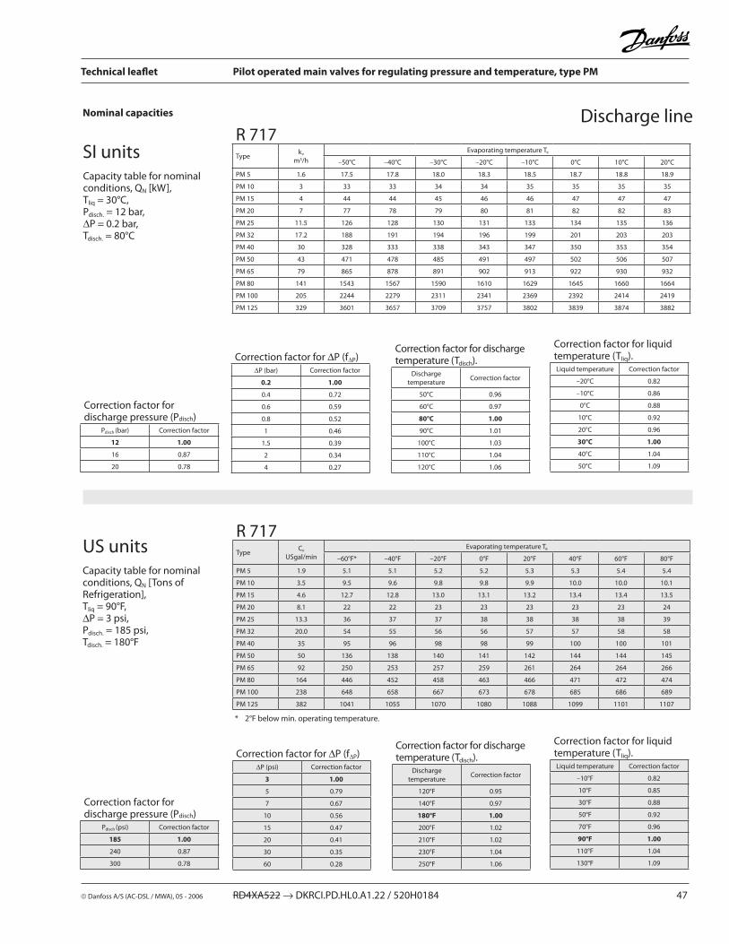
Danfoss A/S (AC-DSL / MWA), 05 - �006 RD4XA5�� → DKRCI.PD.HL0.A1.�� / 5�0H0184 47
Technical leaflet Pilot operated main valves for regulating pressure and temperature, type PM
Capacity table for nominal conditions, QN [kW], Tliq = 30°C, Pdisch. = 1� bar, ∆P = 0.� bar, Tdisch. = 80°C
Nominal capacities Discharge line
SI units
US units
* �°F below min. operating temperature.
R 717Type
Cv
USgal/min
Evaporating temperature Te
–60°F* –40°F –�0°F 0°F �0°F 40°F 60°F 80°F
PM 5 1.9 5.1 5.1 5.� 5.� 5.3 5.3 5.4 5.4
PM 10 3.5 9.5 9.6 9.8 9.8 9.9 10.0 10.0 10.1
PM 15 4.6 1�.7 1�.8 13.0 13.1 13.� 13.4 13.4 13.5
PM �0 8.1 �� �� �3 �3 �3 �3 �3 �4
PM �5 13.3 36 37 37 38 38 38 38 39
PM 3� �0.0 54 55 56 56 57 57 58 58
PM 40 35 95 96 98 98 99 100 100 101
PM 50 50 136 138 140 141 14� 144 144 145
PM 65 9� �50 �53 �57 �59 �61 �64 �64 �66
PM 80 164 446 45� 458 463 466 471 47� 474
PM 100 �38 648 658 667 673 678 685 686 689
PM 1�5 38� 1041 1055 1070 1080 1088 1099 1101 1107
Capacity table for nominal conditions, QN [Tons of Refrigeration], Tliq = 90°F, ∆P = 3 psi, Pdisch. = 185 psi, Tdisch. = 180°F
R 717Type
kv
m3/h
Evaporating temperature Te
–50°C –40°C –30°C –�0°C –10°C 0°C 10°C �0°C
PM 5 1.6 17.5 17.8 18.0 18.3 18.5 18.7 18.8 18.9
PM 10 3 33 33 34 34 35 35 35 35
PM 15 4 44 44 45 46 46 47 47 47
PM �0 7 77 78 79 80 81 8� 8� 83
PM �5 11.5 1�6 1�8 130 131 133 134 135 136
PM 3� 17.� 188 191 194 196 199 �01 �03 �03
PM 40 30 3�8 333 338 343 347 350 353 354
PM 50 43 471 478 485 491 497 50� 506 507
PM 65 79 865 878 891 90� 913 9�� 930 93�
PM 80 141 1543 1567 1590 1610 16�9 1645 1660 1664
PM 100 �05 ��44 ��79 �311 �341 �369 �39� �414 �419
PM 1�5 3�9 3601 3657 3709 3757 380� 3839 3874 388�
Correction factor for discharge pressure (Pdisch)
Pdisch (bar) Correction factor
12 1.00
16 0.87
�0 0.78
Correction factor for ∆P (f∆P)∆P (bar) Correction factor
0.2 1.00
0.4 0.7�
0.6 0.59
0.8 0.5�
1 0.46
1.5 0.39
� 0.34
4 0.�7
Correction factor for discharge temperature (Tdisch).
Discharge temperature
Correction factor
50°C 0.96
60°C 0.97
80°C 1.00
90°C 1.01
100°C 1.03
110°C 1.04
1�0°C 1.06
Correction factor for liquid temperature (Tliq).Liquid temperature Correction factor
–�0°C 0.8�
–10°C 0.86
0°C 0.88
10°C 0.9�
�0°C 0.96
30°C 1.00
40°C 1.04
50°C 1.09
Correction factor for discharge pressure (Pdisch)
Pdisch (psi) Correction factor
185 1.00
�40 0.87
300 0.78
Correction factor for ∆P (f∆P)∆P (psi) Correction factor
3 1.00
5 0.79
7 0.67
10 0.56
15 0.47
�0 0.41
30 0.35
60 0.�8
Correction factor for discharge temperature (Tdisch).
Discharge temperature
Correction factor
1�0°F 0.95
140°F 0.97
180°F 1.00
�00°F 1.0�
�10°F 1.0�
�30°F 1.04
�50°F 1.06
Correction factor for liquid temperature (Tliq).Liquid temperature Correction factor
–10°F 0.8�
10°F 0.85
30°F 0.88
50°F 0.9�
70°F 0.96
90°F 1.00
110°F 1.04
130°F 1.09

48 RD4XA5�� → DKRCI.PD.HL0.A1.�� / 5�0H0184 Danfoss A/S (AC-DSL / MWA), 05 - �006
Technical leaflet Pilot operated main valves for regulating pressure and temperature, type PM
Nominal capacities
Capacity table for nominal conditions, QN [kW], Tliq = 30°C, Pdisch. = 1� bar, ∆P = 0.� bar, Tdisch. = 80°C
Discharge line
SI units
US units
*) �°F below min. operating temperature.
Capacity table for nominal conditions, QN [Tons of Refrigeration], Tliq = 90°F, ∆P = 3 psi, Pdisch. = 185 psi, Tdisch. = 180 °F
R ��Type
kv
m3/h
Evaporating temperature Te
–50°C –40°C –30°C –�0°C –10°C 0°C 10°C �0°C
PM 5 1.6 5.5 5.7 5.9 6.0 6.� 6.3 6.5 6.6
PM 10 3 10.4 10.7 11.0 11.3 11.6 11.9 1�.1 1�.4
PM 15 4 13.8 14.3 14.7 15.1 15.5 15.9 16.� 16.5
PM �0 7 �4.� �5.0 �5.8 �6.5 �7.1 �7.8 �8.3 �8.8
PM �5 11.5 39.8 41.1 4�.3 43.5 44.6 45.6 46.5 47.4
PM 3� 17.� 59.5 61.4 63.3 65.0 66.7 68.� 69.6 70.9
PM 40 30 103.8 107.� 110.4 113.4 116.3 119.0 1�1.4 1�3.6
PM 50 43 148.8 153.6 158.� 16�.6 166.7 170.6 174.0 177.�
PM 65 79 �73.4 �8�.� �90.7 �98.7 306.3 313.4 319.8 3�5.5
PM 80 141 488.0 503.7 518.9 533.0 546.7 559.3 570.7 580.9
PM 100 �05 709.5 73�.3 754.4 775.0 794.8 813.� 8�9.7 844.6
PM 1�5 3�9 1138.7 1175.� 1�10.7 1�43.8 1�75.6 1305.0 1331.6 1355.5
Correction factor for discharge pressure (Pdisch)
Pdisch (bar) Correction factor
12 1.00
16 0.87
�0 0.78
Correction factor for ∆P (f∆P)∆P (bar) Correction factor
0.2 1.00
0.4 0.7�
0.6 0.59
0.8 0.5�
1 0.46
1.5 0.39
� 0.34
4 0.�7
Correction factor for discharge temperature (Tdisch).
Discharge temperature
Correction factor
50°C 0.96
60°C 0.97
80°C 1.00
90°C 1.01
100°C 1.03
110°C 1.04
1�0°C 1.06
Correction factor for liquid temperature (Tliq).Liquid temperature Correction factor
–�0°C 0.71
–10°C 0.75
0°C 0.80
10°C 0.86
�0°C 0.9�
30°C 1.00
40°C 1.09
50°C 1.��
R ��Type
Cv
USgal/min
Evaporating temperature Te
–60°F* –40°F –�0°F 0°F �0°F 40°F 60°F 80°F
PM 5 1.9 1.6 1.6 1.7 1.7 1.8 1.8 1.9 1.9
PM 10 3.5 3.0 3.1 3.� 3.3 3.4 3.5 3.5 3.6
PM 15 4.6 4.0 4.1 4.� 4.4 4.5 4.6 4.7 4.8
PM �0 8.1 6.9 7.� 7.4 7.6 7.9 8.1 8.� 8.4
PM �5 13.3 11.4 11.8 1�.� 1�.6 1�.9 13.� 13.5 13.8
PM 3� �0.0 17.0 17.6 18.� 18.8 19.3 19.8 �0.3 �0.6
PM 40 35 �9.7 30.8 31.8 3�.8 33.7 34.5 35.3 36.0
PM 50 50 4�.6 44.1 45.6 47.0 48.3 49.5 50.6 51.5
PM 65 9� 78.� 81.0 83.7 86.3 88.7 90.9 93.0 94.7
PM 80 164 139.6 144.6 149.4 154.0 158.3 16�.� 166.0 169.0
PM 100 �38 �03.0 �10.� �17.� ��3.9 �30.1 �35.8 �41.4 �45.7
PM 1�5 38� 3�5.7 337.4 348.6 359.3 369.3 378.5 387.4 394.3
Correction factor for discharge pressure (Pdisch)
Pdisch (psi) Correction factor
185 1.00
�40 0.87
300 0.78
Correction factor for ∆P (f∆P)∆P (psi) Correction factor
3 1.00
5 0.79
7 0.67
10 0.56
15 0.47
�0 0.41
30 0.35
60 0.�8
Correction factor for discharge temperature (Tdisch).
Discharge temperature
Correction factor
1�0°F 0.95
140°F 0.97
180°F 1.00
�00°F 1.0�
�10°F 1.0�
�30°F 1.04
�50°F 1.06
Correction factor for liquid temperature (Tliq).Liquid temperature Correction factor
–10°F 0.73
10°F 0.77
30°F 0.8�
50°F 0.87
70°F 0.93
90°F 1.00
110°F 1.09
130°F 1.�0

Danfoss A/S (AC-DSL / MWA), 05 - �006 RD4XA5�� → DKRCI.PD.HL0.A1.�� / 5�0H0184 49
Technical leaflet Pilot operated main valves for regulating pressure and temperature, type PM
Discharge lineNominal capacities
SI units
US units
* �°F below min. operating temperature.
Capacity table for nominal conditions, QN [kW], Tliq = 30°C, Pdisch = 8 bar, ∆P = 0.� barTdisch = 80 °C
Capacity table for nominal conditions, QN [Tons of Refrigeration], Tliq = 90°F, ∆P = 3 psiPdisch = 1�0 psi,Tdisch = 180 °F
R 134aType
kv
m3/h
Evaporating temperature Te
–50°C –40°C –30°C –�0°C –10°C 0°C 10°C �0°C
PM 5 1.6 - 4.3 4.5 4.7 4.9 5.1 5.3 5.5
PM 10 3 - 8.1 8.5 8.9 9.� 9.6 10.0 10.3
PM 15 4 - 10.8 11.3 11.8 1�.3 1�.8 13.3 13.7
PM �0 7 - 18.9 19.8 �0.7 �1.6 ��.4 �3.� �4.0
PM �5 11.5 - 31.1 3�.5 34.0 35.4 36.8 38.� 39.5
PM 3� 17.� - 46.5 48.7 50.9 53.0 55.1 57.1 59.0
PM 40 30 - 81.1 84.9 88.7 9�.4 96.1 99.6 10�.9
PM 50 43 - 116.� 1�1.7 1�7.� 13�.5 137.7 14�.7 147.6
PM 65 79 - �13.5 ��3.6 �33.7 �43.4 �53.0 �6�.3 �71.1
PM 80 141 - 381.1 399.1 417.1 434.4 451.6 468.1 483.9
PM 100 �05 - 554.1 580.� 606.3 631.6 656.5 680.5 703.5
PM 1�5 3�9 - 889.� 931.� 973.1 1013.7 1053.6 109�.� 11�9.0
Correction factor for discharge pressure (Pdisch)
Pdisch (bar) Correction factor
8 1.00
1� 0.8�
16 0.70
�0 0.6�
Correction factor for ∆P (f∆P)∆P (bar) Correction factor
0.2 1.00
0.4 0.7�
0.6 0.59
0.8 0.5�
1 0.46
1.5 0.39
� 0.34
4 0.�7
Correction factor for discharge temperature (Tdisch).
Discharge temperature
Correction factor
50°C 0.96
60°C 0.97
80°C 1.00
90°C 1.01
100°C 1.03
110°C 1.04
1�0°C 1.06
Correction factor for liquid temperature (Tliq).Liquid temperature Correction factor
–�0°C 0.66
–10°C 0.70
0°C 0.76
10°C 0.8�
�0°C 0.90
30°C 1.00
40°C 1.13
50°C 1.�9
R 134aType
Cv
USgal/min
Evaporating temperature Te
–60°F* –40°F –�0°F 0°F �0°F 40°F 60°F 80°F
PM 5 1.9 - 1.3 1.3 1.4 1.5 1.5 1.6 1.6
PM 10 3.5 - �.4 �.5 �.6 �.7 �.8 3.0 3.1
PM 15 4.6 - 3.1 3.3 3.5 3.6 3.8 4.0 4.1
PM �0 8.1 - 5.5 5.8 6.1 6.4 6.6 6.9 7.�
PM �5 13.3 - 9.0 9.5 10.0 10.5 10.9 11.4 11.8
PM 3� �0 - 13.5 14.3 15.0 15.7 16.3 17.0 17.6
PM 40 35 - �3.6 �4.9 �6.1 �7.3 �8.5 �9.7 30.8
PM 50 50 - 33.8 35.6 37.4 39.� 40.8 4�.6 44.1
PM 65 9� - 6�.� 65.5 68.7 71.9 75.0 78.3 81.1
PM 80 164 - 110.9 116.9 1��.7 1�8.4 133.9 139.7 144.7
PM 100 �38 - 161.3 169.9 178.4 186.7 194.7 �03.1 �10.4
PM 1�5 38� - �58.8 �7�.7 �86.3 �99.6 31�.5 3�6.0 337.6
Correction factor for discharge pressure (Pdisch)
Pdisch (psi) Correction factor
120 1.00
185 0.83
�40 0.71
300 0.64
Correction factor for ∆P (f∆P)∆P (psi) Correction factor
3 1.00
5 0.79
7 0.67
10 0.56
15 0.47
�0 0.41
30 0.35
60 0.�8
Correction factor for discharge temperature (Tdisch).
Discharge temperature
Correction factor
1�0°F 0.95
140°F 0.97
180°F 1.00
�00°F 1.0�
�10°F 1.0�
�30°F 1.04
�50°F 1.05
Correction factor for liquid temperature (Tliq).Liquid temperature Correction factor
–10°F 0.64
10°F 0.68
30°F 0.74
50°F 0.81
70°F 0.89
90°F 1.00
110°F 1.15
130°F 1.35

50 RD4XA5�� → DKRCI.PD.HL0.A1.�� / 5�0H0184 Danfoss A/S (AC-DSL / MWA), 05 - �006
Technical leaflet Pilot operated main valves for regulating pressure and temperature, type PM
Discharge lineNominal capacities
Capacity table for nominal conditions, QN [kW], Tliq = 30°C, Pdisch = 1� bar∆P = 0.� bar, Tdisch = 80 °C
SI units
US units
* �°F below min. operating temperature.
Capacity table for nominal conditions, QN [Tons of Refrigeration], Tliq = 90°F, ∆P = 3 psi,Pdisch = 185 psi, Tdisch = 180°F
R 404AType kv
m3/h Evaporating temperature Te
–50°C –40°C –30°C –�0°C –10°C 0°C 10°C �0°C
PM 5 1.6 3.7 3.9 4.� 4.4 4.7 4.9 5.1 5.3
PM 10 3 6.9 7.4 7.8 8.3 8.8 9.� 9.6 9.9
PM 15 4 9.� 9.8 10.5 11.1 11.7 1�.3 1�.8 13.3
PM �0 7 16.0 17.� 18.3 19.4 �0 �1 �� �3
PM �5 11.5 �6 �8 30 3� 34 35 37 38
PM 3� 17.� 39 4� 45 48 50 53 55 57
PM 40 30 69 74 78 83 88 9� 96 99
PM 50 43 99 106 11� 119 1�6 13� 138 143
PM 65 79 181 194 �07 �19 �31 �4� �53 �6�
PM 80 141 3�3 346 369 391 41� 43� 451 468
PM 100 �05 470 503 536 568 599 6�9 656 680
PM 1�5 3�9 754 807 860 91� 96� 1009 105� 1091
Correction factor for discharge pressure (Pdisch)
Pdisch (bar) Correction factor
12 1
16 0.87
�0 0.78
Correction factor for ∆P (f∆P)∆P (bar) Correction factor
0.2 1.00
0.4 0.7�
0.6 0.59
0.8 0.5�
1 0.46
1.5 0.39
� 0.34
4 0.�7
Correction factor for discharge temperature (Tdisch).
Discharge temperature
Correction factor
50°C 0.96
60°C 0.97
80°C 1.00
90°C 1.01
100°C 1.03
110°C 1.04
1�0°C 1.06
Correction factor for liquid temperature (Tliq).Liquid temperature Correction factor
–�0°C 0.55
–10°C 0.60
0°C 0.66
10°C 0.74
�0°C 0.85
30°C 1.00
40°C 1.�3
50°C 1.68
R 404AType
Cv
USgal/min
Evaporating temperature Te
–60°F* –40°F –�0°F 0°F �0°F 40°F 60°F 80°F
PM 5 1.9 1.0 1.1 1.� 1.3 1.3 1.4 1.5 1.5
PM 10 3.5 1.9 �.1 �.� �.4 �.5 �.7 �.8 �.9
PM 15 4.6 �.6 �.8 3.0 3.� 3.4 3.5 3.7 3.9
PM �0 8.1 4.5 4.8 5.� 5.6 5.9 6.� 6.5 6.8
PM �5 13.3 7.4 8.0 8.6 9.1 9.7 10.� 10.7 11.1
PM 3� �0 11.0 11.9 1�.8 13.7 14.5 15.� 16.0 16.6
PM 40 35 19.� �1 �� �4 �5 �7 �8 �9
PM 50 50 �8 30 3� 34 36 38 40 41
PM 65 9� 51 55 59 63 66 70 73 76
PM 80 164 90 98 105 11� 119 1�5 131 136
PM 100 �38 131 14� 15� 163 173 18� 191 198
PM 1�5 38� �10 ��8 �45 �61 �77 �9� 306 317
Correction factor for discharge pressure (Pdisch)
Pdisch (psi) Correction factor
185 1
�40 0.87
300 0.78
Correction factor for ∆P (f∆P)∆P (psi) Correction factor
3 1.00
5 0.79
7 0.67
10 0.56
15 0.47
�0 0.41
30 0.35
60 0.�8
Correction factor for discharge temperature (Tdisch).
Discharge temperature
Correction factor
1�0°F 0.95
140°F 0.97
180°F 1.00
�00°F 1.0�
�10°F 1.0�
�30°F 1.04
�50°F 1.05
Correction factor for liquid temperature (Tliq).Liquid temperature Correction factor
–10°F 0.5�
10°F 0.57
30°F 0.63
50°F 0.7�
70°F 0.83
90°F 1.00
110°F 1.�9
130°F 1.9�

Danfoss A/S (AC-DSL / MWA), 05 - �006 RD4XA5�� → DKRCI.PD.HL0.A1.�� / 5�0H0184 51
Technical leaflet Pilot operated main valves for regulating pressure and temperature, type PM

5� RD4XA5�� → DKRCI.PD.HL0.A1.�� / 5�0H0184 Danfoss A/S (AC-DSL / MWA), 05 - �006
Technical leaflet Pilot operated main valves for regulating pressure and temperature, type PM