piezoelectric vibration damping study for rotating ... · pdf filepiezoelectric damping on...
TRANSCRIPT

James B. MinGlenn Research Center, Cleveland, Ohio
Kirsten P. DuffyUniversity of Toledo, Toledo, Ohio
Benjamin B. Choi and Andrew J. ProvenzaGlenn Research Center, Cleveland, Ohio
Nicholas KrayGeneral Electric Aviation, Cincinnati, Ohio
Piezoelectric Vibration Damping Study for Rotating Composite Fan Blades
NASA/TM—2012-217648
August 2012
https://ntrs.nasa.gov/search.jsp?R=20120013823 2018-04-25T14:17:37+00:00Z

NASA STI Program . . . in Profile
Since its founding, NASA has been dedicated to the advancement of aeronautics and space science. The NASA Scientific and Technical Information (STI) program plays a key part in helping NASA maintain this important role.
The NASA STI Program operates under the auspices of the Agency Chief Information Officer. It collects, organizes, provides for archiving, and disseminates NASA’s STI. The NASA STI program provides access to the NASA Aeronautics and Space Database and its public interface, the NASA Technical Reports Server, thus providing one of the largest collections of aeronautical and space science STI in the world. Results are published in both non-NASA channels and by NASA in the NASA STI Report Series, which includes the following report types: • TECHNICAL PUBLICATION. Reports of
completed research or a major significant phase of research that present the results of NASA programs and include extensive data or theoretical analysis. Includes compilations of significant scientific and technical data and information deemed to be of continuing reference value. NASA counterpart of peer-reviewed formal professional papers but has less stringent limitations on manuscript length and extent of graphic presentations.
• TECHNICAL MEMORANDUM. Scientific
and technical findings that are preliminary or of specialized interest, e.g., quick release reports, working papers, and bibliographies that contain minimal annotation. Does not contain extensive analysis.
• CONTRACTOR REPORT. Scientific and
technical findings by NASA-sponsored contractors and grantees.
• CONFERENCE PUBLICATION. Collected papers from scientific and technical conferences, symposia, seminars, or other meetings sponsored or cosponsored by NASA.
• SPECIAL PUBLICATION. Scientific,
technical, or historical information from NASA programs, projects, and missions, often concerned with subjects having substantial public interest.
• TECHNICAL TRANSLATION. English-
language translations of foreign scientific and technical material pertinent to NASA’s mission.
Specialized services also include creating custom thesauri, building customized databases, organizing and publishing research results.
For more information about the NASA STI program, see the following:
• Access the NASA STI program home page at http://www.sti.nasa.gov
• E-mail your question to [email protected] • Fax your question to the NASA STI
Information Desk at 443–757–5803 • Phone the NASA STI Information Desk at 443–757–5802 • Write to:
STI Information Desk NASA Center for AeroSpace Information 7115 Standard Drive Hanover, MD 21076–1320
James B. MinGlenn Research Center, Cleveland, Ohio
Kirsten P. DuffyUniversity of Toledo, Toledo, Ohio
Benjamin B. Choi and Andrew J. ProvenzaGlenn Research Center, Cleveland, Ohio
Nicholas KrayGeneral Electric Aviation, Cincinnati, Ohio
Piezoelectric Vibration Damping Study for Rotating Composite Fan Blades
NASA/TM—2012-217648
August 2012
National Aeronautics andSpace Administration
Glenn Research Center Cleveland, Ohio 44135
Prepared for the53rd Structures, Structural Dynamics, and Materials Conferencecosponsored by the AIAA, ASME, ASCE, AHS, and ASCHonolulu, Hawaii, April 23–26, 2012

Acknowledgments
Authors express thanks to George Stefko and Milind Bakhle for valuable technical discussions; Carlos Morrison for a wireless inductive power transfer device development task during the course of the project; Karen Bartos helped for blade mesh modification; George Carlson for Ansys Multiphysics discussions; Greg Gemeinhardt for blade composite properties and ply-layup information; Ian Prentice for the original GE blade mesh; Karen Taminger, Ajay Misra, Leslie Greenbauer-Seng for the project support with the Subsonic Fixed Wing Project of the NASA Fundamental Aeronautics Program. This work was a collaborative effort between NASA GRC and GE Aviation through NASA Space Act Agreement SAA3-260, task order 31.
Available from
NASA Center for Aerospace Information7115 Standard DriveHanover, MD 21076–1320
National Technical Information Service5301 Shawnee Road
Alexandria, VA 22312
Available electronically at http://www.sti.nasa.gov
Trade names and trademarks are used in this report for identification only. Their usage does not constitute an official endorsement, either expressed or implied, by the National Aeronautics and
Space Administration.
This work was sponsored by the Fundamental Aeronautics Program at the NASA Glenn Research Center.
Level of Review: This material has been technically reviewed by technical management.

NASA/TM—2012-217648 1
Piezoelectric Vibration Damping Study for Rotating Composite Fan Blades
James B. Min
National Aeronautics and Space Administration Glenn Research Center Cleveland, Ohio 44135
Kirsten P. Duffy
University of Toledo Toledo, Ohio 43606
Benjamin B. Choi and Andrew J. Provenza
National Aeronautics and Space Administration Glenn Research Center Cleveland, Ohio 44135
Nicholas Kray
General Electric Aviation Cincinnati, Ohio 45069
Abstract Resonant vibrations of aircraft engine blades cause blade fatigue problems in engines, which can lead
to thicker and aerodynamically lower performing blade designs, increasing engine weight, fuel burn, and maintenance costs. In order to mitigate undesirable blade vibration levels, active piezoelectric vibration control has been investigated, potentially enabling thinner blade designs for higher performing blades and minimizing blade fatigue problems. While the piezoelectric damping idea has been investigated by other researchers over the years, very little study has been done including rotational effects. The present study attempts to fill this void. The particular objectives of this study were: (a) to develop and analyze a multiphysics piezoelectric finite element composite blade model for harmonic forced vibration response analysis coupled with a tuned RLC circuit for rotating engine blade conditions, (b) to validate a numerical model with experimental test data, and (c) to achieve a cost-effective numerical modeling capability which enables simulation of rotating blades within the NASA Glenn Research Center (GRC) Dynamic Spin Rig Facility. A numerical and experimental study for rotating piezoelectric composite subscale fan blades was performed. It was also proved that the proposed numerical method is feasible and effective when applied to the rotating blade base excitation model. The experimental test and multiphysics finite element modeling technique described in this paper show that piezoelectric vibration damping can significantly reduce vibrations of aircraft engine composite fan blades.
1.0 Introduction The requirements for advanced aircraft engine components lead to designs which are more
lightweight and efficient, yet more susceptible to excessive vibration, complex dynamic behavior, and uncertain durability and reliability. This complex nature of the dynamic behavior also leads to thicker blade designs, hence increased fuel burn, increased noise, potentially reduced engine life, and increased maintenance costs. As part of the NASA Fundamental Aeronautics Program (FAP) Subsonic Fixed Wing Project, NASA Glenn Research Center (GRC) is investigating potential technologies that support the FAP’s goals for lighter, quieter, and more efficient aircraft.

NASA/TM—2012-217648 2
One of challenge areas in the development of highly efficient and lighter aircraft engines is that high performance rotating blades are subject to high cycle fatigue (HCF) limitations as a result of high vibratory stresses. HCF accounts for fifty-six percent of major aircraft engine failures and ultimately limits the service life of most critical rotating components. An estimated $400M is expended annually for HCF related inspection and maintenance of military aircraft alone (Ref. 1).
Excessive vibration of turbomachinery blades requires damping treatments to mitigate excessive vibration levels which cause HCF problems. Designing damping treatments for rotating blades in an extreme engine environment is a difficult task with various factors such as high temperatures and centrifugal accelerations. Several damping methods have been investigated by NASA researchers for use in aircraft engine blades, including viscoelastic damping of scaled composite fan blades (Ref. 2), tuned impact damping (Ref. 3), plasma sprayed damping coatings (Ref. 4), and high-damping high-temperature shape memory alloy materials (Ref. 5).
Piezoelectric damping has also been explored as a solution for damping treatment. When a piezoelectric material experiences a strain, a portion of that energy becomes dielectric energy and is stored in the material. In this sense, piezoelectric materials behave electrically as a capacitor. A manufactured material with a high electromechanical coupling factor is lead zirconate titanate (PZT) that is used in many piezoelectric actuators and sensors (Ref. 6). Many researchers have investigated piezoelectric materials in parallel with electric circuits that absorb the vibration energy of components. A survey of smart structures state-of-the-art has been reviewed (Ref. 7). A method to determine the effective damping of a shunted piezoelectric material has been detailed (Ref. 8). Lesieutre (Ref. 6) has also described the different types of shunt circuits and how they affect damping behavior.
For application of piezoelectric dampers to turbomachinery blades, previous work was done with non-rotational applications. Hilbert et al. (Ref. 9) acquired a patent for shunted piezoelectric damping of blades, where piezoelectric patches were placed below the blade platform. Livet (Ref. 10) examined negative capacitance shunted piezoelectric materials on beams for turbomachinery blade application. Cross and Fleeter (Ref. 11) investigated the application of shunted piezoelectric elements to provide passive damping to control flow-induced vibrations of chordwise bending mode in a low-aspect-ratio stator vanes. Piezoelectric networks have also been studied for reduction of mistuned blade vibration levels through blade coupling (Ref. 12). Researchers at GRC also carried out the design and implementation of an experimental system that utilized stator vane mounted piezoelectric actuators to control fan-stator interaction noise in a simulated turbo-fan engine (Ref. 13). More recently, a resonant damping study using shunted piezoelectric patches on plate specimens was conducted (Refs. 14 to 16), wherein the shunted piezoelectric circuit damping finite element (FE) models were developed using Ansys Multiphysics software for the resistive and inductive circuit piezoelectric simulations. A frequency-switching concept for avoiding resonant response in blades was also introduced and a significant amplitude reduction was reported (Ref. 17). These efforts reported significant reduction in resonant response utilizing various techniques; however their investigations were only non-spinning demonstrations.
While various research has been performed on the use of a shunted piezoelectric material connected to electric circuits for controlling vibration damping in a stationery frame, very little study has been done to assess rotational effects. The present study attempts to fill this void by demonstrating the feasibility of piezoelectric damping on rotating fan blades through design, build, and testing of piezoelectric subscale fan blade specimens subjected to high rotational speeds. Specifically, the objectives of this study were: (a) to develop multiphysics finite element modeling techniques for harmonic forced vibration response analysis coupled with shunted piezoelectric circuits under rotation, (b) to demonstrate the shunted piezoelectric blade damping control techniques by utilizing experimental spin rig test, and (c) to validate numerical modeling techniques by a comparison with experimental spin test results and vice versa.
The resistive inductive (RL) shunted circuit technique is generally accepted for passive vibration damping control of a single mode or multi-modes (Ref. 18). However, a major problem with this approach is the large inductor size and mass for low frequency-tuned resonant circuit. Consequently, many researchers proposed the use of synthetic inductors (Refs. 10 and 11) to reduce the weight and volume of the circuits. It required a constant power supply, and its size was still considerably large.

NASA/TM—2012-217648 3
Nevertheless, the RL shunt or synthetic inductor is suitable for stationary frame applications. For turbomachinery applications, however, an implementation issue can arise when applied to the limited space in which the blades reside in the engine. Further, there is the risk of rotor imbalance with operation at high centrifugal loads. Therefore, our effort at GRC has been to investigate the effectiveness of a digital code shunt circuit technique (Ref. 19) using the subscale rotor blade specimens in the GRC Dynamic Spin Rig Facility (Ref. 20).
The current study was focused on a resonant damping control using surface-mounted piezoelectric patches on graphite-epoxy composite subscale fan blade specimens. Tests were performed for both non-spinning and spinning conditions. Ansys Multiphysics software was utilized to incorporate our specific modeling techniques in the modeling effort and utilized along with experimental tests to validate the numerical simulation model and vice versa. Some earlier test and analysis work conducted at GRC with piezoelectric beam specimens is described (Ref. 16). Our expanded research using plate specimens under centrifugal loading conditions at room temperature showed that shunted piezoelectric damping techniques have great potential to reduce plate vibrations under a centrifugal load (Refs. 14 and 15). The validated numerical models and the experimental test results obtained from these earlier studies allowed us to extend our effort for design and optimization of more complex actual turbomachinery rotor blade systems.
To complete the study, a careful combination of experimental test and analysis was performed with the intent of achieving the objectives described earlier. The target blade specimen for the present study was a General Electric Aviation (GE) GEnx engine subscale composite fan blade. The experimental test was performed by spinning the rotor in a vacuum tank with excitation provided active magnetic bearings. This rig allows for the measurement of structural damping by itself since the aerodynamic forces are not present in the test. Also, the use of commercially available measurement tools and realistic blade hardware was intended to make the study as accurate as possible in applying the results of our feasibility study to real problems encountered in the design of advanced turbomachinery aircraft engines.
The numerical component of this study was performed not only to develop an accurate analytical tool of predictions to compare with the spin rig test results, but also to guide the selection and location of the actuator and sensor for the experimental test. The large mass method finite element technique was developed for the forced vibration response analyses of blades subjected to blade base acceleration, which is generated by the active magnetic bearings directly from the rotor to the blade structure in the form of acceleration loads. This numerical technique was incorporated into Ansys Multiphysics program to solve the problem.
Experimental blade spin test and multiphysics finite element modeling techniques described in this paper show that piezoelectric damping can significantly reduce vibrations of composite fan blades. Our study results should serve to enhance the research to further investigate piezoelectric blade vibration control in real engine environments.
2.0 Materials and Approaches Based on the technical challenges and requirements learned from our previous turbomachinery rotor
blade research, our study was focused on the first bending (1B) mode resonant damping control using piezoelectric patches on graphite-epoxy composite blade specimens. Test articles were provided by GE Aviation (Ref. 21), and testing and finite element analysis were performed at GRC. While the piezoelectric elements can be embedded within the composite blades the subscale blades are very thin, so the piezoelectric patches were surface mounted.
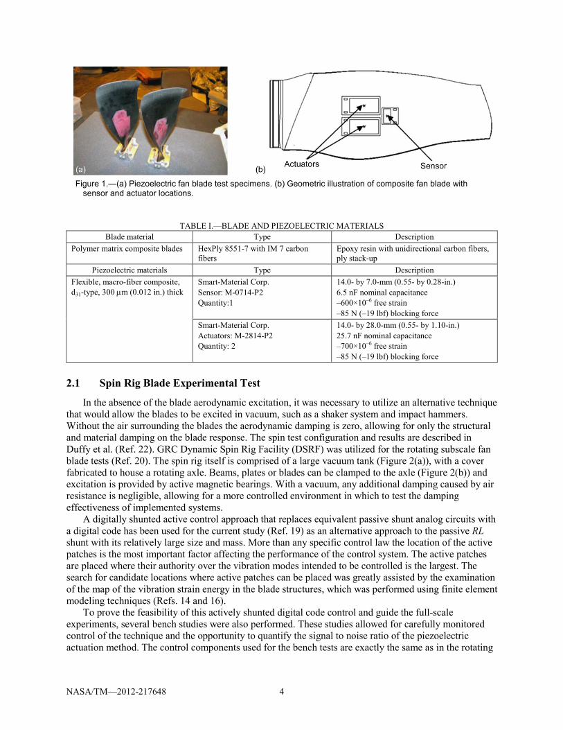
Figure 1(a) and (b) show the subscale composite piezoelectric fan blade specimen studied with a combination of numerical predictions and experimental spin tests. Table I describes the materials used in the blades.
Since a goal of this study was to develop and analyze the forced vibration response model of an actual fan blade configuration, a realistic simulation was also wanted in concert to characterize the behavior of an actual blade subjected to the proper blade excitation and structural conditions seen during operation of the blade spin test.
NASA/TM—2012-217648 4
Figure 1.—(a) Piezoelectric fan blade test specimens. (b) Geometric illustration of composite fan blade with
sensor and actuator locations.
TABLE I.—BLADE AND PIEZOELECTRIC MATERIALS Blade material Type Description
Polymer matrix composite blades HexPly 8551-7 with IM 7 carbon fibers
Epoxy resin with unidirectional carbon fibers, ply stack-up
Piezoelectric materials Type Description Flexible, macro-fiber composite, d31-type, 300 µm (0.012 in.) thick
Smart-Material Corp. Sensor: M-0714-P2 Quantity:1
14.0- by 7.0-mm (0.55- by 0.28-in.) 6.5 nF nominal capacitance –600×10–6 free strain –85 N (–19 lbf) blocking force
Smart-Material Corp. Actuators: M-2814-P2 Quantity: 2
14.0- by 28.0-mm (0.55- by 1.10-in.) 25.7 nF nominal capacitance –700×10–6 free strain –85 N (–19 lbf) blocking force
2.1 Spin Rig Blade Experimental Test
In the absence of the blade aerodynamic excitation, it was necessary to utilize an alternative technique that would allow the blades to be excited in vacuum, such as a shaker system and impact hammers. Without the air surrounding the blades the aerodynamic damping is zero, allowing for only the structural and material damping on the blade response. The spin test configuration and results are described in Duffy et al. (Ref. 22). GRC Dynamic Spin Rig Facility (DSRF) was utilized for the rotating subscale fan blade tests (Ref. 20). The spin rig itself is comprised of a large vacuum tank (Figure 2(a)), with a cover fabricated to house a rotating axle. Beams, plates or blades can be clamped to the axle (Figure 2(b)) and excitation is provided by active magnetic bearings. With a vacuum, any additional damping caused by air resistance is negligible, allowing for a more controlled environment in which to test the damping effectiveness of implemented systems.
A digitally shunted active control approach that replaces equivalent passive shunt analog circuits with a digital code has been used for the current study (Ref. 19) as an alternative approach to the passive RL shunt with its relatively large size and mass. More than any specific control law the location of the active patches is the most important factor affecting the performance of the control system. The active patches are placed where their authority over the vibration modes intended to be controlled is the largest. The search for candidate locations where active patches can be placed was greatly assisted by the examination of the map of the vibration strain energy in the blade structures, which was performed using finite element modeling techniques (Refs. 14 and 16).
To prove the feasibility of this actively shunted digital code control and guide the full-scale experiments, several bench studies were also performed. These studies allowed for carefully monitored control of the technique and the opportunity to quantify the signal to noise ratio of the piezoelectric actuation method. The control components used for the bench tests are exactly the same as in the rotating

NASA/TM—2012-217648 5
experiments and more detail is described in (Refs. 19 and 22). A photograph of the entire test system used for our bench-top experimental test is shown in Figure 3.
Many researchers tested their novel ideas by imposing stress in the airfoil to simulate rotational speed (Ref. 10), but it is very difficult to obtain a reliable and repeatable measurement due to all of the uncertainties associated with applying a distributed force. The only accurate way to perform vibration response experiments on the rotating blades is to use a spin test facility that places the blade in a realistic rotating environment.
To determine if the piezoelectric component actuates the rotating blades in the proper manner, it is important to evaluate the experimental test resonance frequency as a function of rotor speed in conjunction with the finite element analysis. The analytical approaches described in the following section were used for the modeling objective.
Figure 2.—(a) Vacuum tank with cover. (b) Subscale GEnx piezoelectric composite fan blades
in GRC spin rig facility.
Figure 3.—Experimental bench-top test assembly.

NASA/TM—2012-217648 6
2.2 Multiphysics Piezoelectric Finite Element Modeling Technique
The finite element prediction was used to provide a comprehensive study of a variety of structural characteristics of a rotating composite fan blade. The first task was to examine the steady stresses due to the centrifugal loading. The second task was to perform a free vibration analysis, allowing for the classification of every resonance mode within the frequency range of interest. This computation also provides information about areas of high stress and how the relative magnitude of these stresses varies with frequency. The third task was to accurately model the structural response of the piezoelectric rotating blade. Accordingly, a finite element method coupled with the piezoelectric sensor/actuator and electrical circuits for predicting forced vibration blade response as a function of the blade rotation has been developed, and incorporated into the Ansys Multiphysics code. This procedure was for a rotating blade model which can predict the strain and stress in harmonically varying blade excitation. While the details of the formulations to solve the rotating blades modal analysis and harmonic forced vibration analysis modeling were described in our previous paper (Ref. 14), its framework components are briefly described in the following subsections.
2.2.1 Geometric Nonlinearity and Spin Softening for Rotating Blade To model the state of rotating composite fan blade, it was modeled using a prestressed modal analysis
method prior to conducting the harmonic forced rotating blade vibration analysis. A blade spin rig experimental test was performed at speeds from zero rpm (revolution per minute) to 5000 rpm even though the GRC Dynamic Spin Rig Facility has the capability of spinning at up to 20,000 rpm.
To capture the true blade behavior in this rotational condition, large strain (or finite strain) method was needed to take into account the blade shape and stiffness changes under high centrifugal rotation. Rigid-body effects (e.g., large rotation) were also taken into account, which separates displacements due to rigid-body motion and those associated with the small strains.
Spin softening (or stress stiffening) of the rotating blade structure due to the stress state was also taken into account, which may also be known as geometric stiffness matrix or initial stress stiffness matrix.
The governing equation of motion for rotation including inertia forces and moments can be expressed in matrix form as:
[ ] [ ] ( ) U M U C U K S F + + + = (1)
where
[ ]M global mass matrix = 1
e n eMe
=∑=
eM element mass matrix = [ ] [ ]T
VN N dVρ∫
[ ]N shape function matrix
ρ element density
[ ]C global damping matrix = 1
e nCe
e
=∑=
n number of elements
K global stiffness of piezoelectric plate including spin softening stiffness due to centrifugal force

NASA/TM—2012-217648 7
S stress stiffening contribution matrix due to large strain and large rotation
[ ] [ ][ ]T
VS G G dv = τ ∫
[ ]G matrix shape function derivatives
[ ]τ matrix of current Cauchy (true) stresses in global coordinate
F global load vector due to rotating body force, vibration shaker excitation force, and piezoelectric voltage and charge
The Block Lanzos Method was used to obtain the resonance frequencies by solving the eigenvalue
problem. This method uses a combination of the automated shift strategy and the Sturm Sequence Check strategy. The two strategies aim to reduce the number of iterations in solving the eigenvalue problem yet maintain good accuracy. After obtaining the frequencies and mode shapes of prestressed piezoelectric blades under rotational conditions, the following steps were applied to build the coupled piezoelectric harmonic forced vibration analysis model to obtain the piezoelectric blade forced vibration responses under rotation.
2.2.2 Equation of Motion and Constitutive Relationship of Piezoelectric Materials Piezoelectric FE equations can be written in terms of nodal displacement U and nodal electric
potential φ for each node. The displacement and potential for each element can be expressed, respectively, as
[ ]
e
Tu e
T
U N U
Nφ
=
φ = φ (2)
where [ ]TuN displacement shape function (transposed)
T
Nφ electrical potential shape function (transposed)
eU nodal displacement
eφ nodal electric potential
The equation of motion corresponding to the piezoelectric actuator and the blade structure can be
assembled in a global system coordinate based on Equations (1) and (2), which includes the degrees of freedom of the piezoelectric actuator (voltages and displacements) and the degrees of freedom of the blade structure (displacements) as follows:
[ ]
0 00 0 0 0
uu uuu uuT
u
U U K K U FCMQK K
φ
φ φφ
+ + = φ φ φ
(3)
where

NASA/TM—2012-217648 8
[ ] [ ] [ ][ ]e
Tuu u uc dVK B B
Ω
= ∫∫∫ [ ] [ ]e
Tu u e dVK B Bφ φ
Ω
= ∫∫∫
[ ]e
T dVK B Bφφ φ φ
Ω
= ε ∫∫∫ [ ] [ ] [ ]e
Tuu u u dVN NM
Ω
= ρ∫∫∫
[ ] [ ]uuuuC K= β
F structural loads
U nodal displacement
eΩ finite element domain
[ ]uuK mechanical stiffness matrix
uK φ piezoelectric coupling matrix
K φφ dielectric stiffness matrix
[ ]uuM mass matrix
[ ]uuC mechanical damping matrix Q electrical loads
φ nodal electric potential
ρ piezoelectric density
[ ]uB , Bφ derivatives of FEM shape functions
[c] elastic coefficients [e] piezoelectric coefficients [ε] dielectric coefficients β damping coefficient
The basic constitutive relationship of piezoelectric materials is also outlined below. A piezoelectric
model requires permittivity (or dielectric constants), the piezoelectric matrix, and the elastic coefficient matrix to be specified as material properties.
[ ] ET C S e E = − (4)
[ ] t SD e S E = + ε (5)
where T stress vector (six components x, y, z, xy, yz, xz)
S strain vector (six components x, y, z, xy, yz, xz)
D electric displacement vector (three components x, y, z)

NASA/TM—2012-217648 9
E electric field vector (three components x, y, z)
Ec stiffness matrix evaluated at constant electric field, i.e., short circuit
[ ]e piezoelectric matrix relating stress/electric field
[ ]te piezoelectric matrix relating stress/electric field (transposed)
S ε dielectric matrix evaluated at constant strains, i.e., mechanically clamped
[ ]d piezoelectric matrix relating strain/electric field
[ ]td piezoelectric matrix relating strain/electric field (transposed)
T ε dielectric matrix evaluated at constant stress, i.e., mechanically free
2.2.3 Piezoelectric Circuit Elements The piezoelectric circuit element, CIRCU94, simulates basic linear electric circuit components that
can be directly connected to the piezoelectric finite element domain. It is suitable for the simulation of circuit-fed piezoelectric dampers for vibration control under the influence of harmonic (sinusoidally varying) forces, currents, displacements, and voltages. CIRCU94 elements were used to model resistor (R) and inductor (L) elements connected to each electrode of the piezoelectric patch. Any number of combinations of loadings is permitted and they need not be in phase, but they must be at the same frequency. The finite element equations for the resistor, inductor, capacitor and current source were derived using the nodal analysis method (Refs. 23 and 24). To be compatible with the system of piezoelectric finite element equations, the nodal analysis method was adopted to maintain the charge balance at each node.
2.2.4 Piezoelectric Vibration Response Analysis Under Harmonic Forced Excitation The harmonic response analysis solves time-dependent equations of motion shown in Equation (1) for
structures undergoing steady-state vibration. All points in the structure are moving at the same known frequency, however, not necessarily in phase. It is known that the presence of damping causes phase shifts. Therefore, the displacements U(t) and electrical potential φ(t) may be defined as:
( ) ( ) j t j tU t U e t e− ω +ψ − ω +ψ= φ = φ (6)
where ω driving frequency ψ phase shift t time Force and charge are expressed as
( ) ( ) j t j tF t F e Q t Q e− ω +ψ − ω +ψ= = (7)
Note that the Q(t) is related to the current I by
( ) ( )1 j tQ t j I e− ω +ψ= ω (8)

NASA/TM—2012-217648 10
Substituting Equations (4) to (8) in Equation (3) yields
2 ˆ
ˆ1ˆ
UU UU UU UT
U
FK j C M K UIK K
j
ϕ
ϕ ϕϕ
+ ω −ω = ϕ ω
(9)
where the superscript “^” represents the complex matrices. Note that peak harmonic response occurs at forcing frequencies that match the natural frequencies of
the piezoelectric composite blade. These formulations described in this section and Equation (9) were utilized to solve for the piezoelectric shunt rotating composite fan blade response in the following section.
3.0 Piezoelectric Rotating Blade Prestressed Modal Analysis Model and Determination of Actuator Location
To assist the setup of the piezoelectric blade spin rig experimental test correctly, piezoelectric finite element blade models were developed for rotating piezoelectric composite fan blades. The blade geometry is derived by geometric scaling of the actual fan blade. The quasi-isotropic bulk material properties from HexPly epoxy resin system with IM7 graphite fiber were used for the fan blade model.
A finite element model of the entire blade model, including the airfoil and “dovetail” attachment was created. It is composed of 3D structural solid element (SOLID95) with twenty nodes having three degrees of freedom per node: translations in the nodal x, y, and z directions. The entire model is made up of 24,395 nodes and 18,960 elements. All displacement directions are constrained at the top surfaces of the dovetail attachment to simulate the disk mounting.
The steady stresses are very important, but the alternating (or vibratory) stresses are the driving factor for a dynamic fatigue stress which can cause fatigue failures when combined with high steady stresses. To get an understanding of the vibratory response, a free vibration modal analysis was needed (without a forcing function). This required calculating the natural frequencies and mode shapes of the blade as a function of the rotor speed.
Both blade spin rig experimental test and finite element modal analysis modeling were performed for both non-spinning and spinning conditions. A finite element analysis modeling technique described in Section 2.2 was incorporated into the Ansys Multiphysics which can model piezoelectric coupled-field elements.
A finite element composite blade mesh without piezoelectric patch was developed and analyzed first to identify an optimal location for the piezoelectric patch placement. Free vibration modal analysis (i.e., with no time dependent loads applied) was then used for natural frequency and mode shape determination. The 1B mode was the target mode in this study. Through finite element analysis, patch positioning, taking into account both modal strain (for best damping) and steady centrifugal strain (affecting material limits), was determined for optimal placement for a higher speed rotational test.
This FE analysis provided a background for the experimental test plan including the optimal use of the piezoelectric actuators and sensors, and setting of the blade experimental test rig operation conditions. Figure 4 to Figure 6 show the blade mode shape and modal strain information at zero spin speed.

NASA/TM—2012-217648 11
Figure 4.—Blade modal displacement contours.
Figure 5.—Blade modal strain contours.

NASA/TM—2012-217648 12
Figure 6.—1B mode—modal displacement and strain on blade pressure side.
Subsequently a piezoelectric finite element blade model with the surface mounted piezoelectric patch was generated. The piezoelectric patch was meshed with SOLID226 which has 20 nodes with four degrees of freedom including the piezoelectric effect per node: translations in the nodal x, y, and z directions, and the electrical potential V. The piezoelectric properties of PZT-5 (Ref. 25) are given in Table II. The poling direction for the piezoelectric patch is vertical through the thickness, and the mechanical boundary condition of the structure is clamped. On each interface between piezoelectric and the blade, the electrical potential is forced to zero. The piezoelectric patch was placed at the 1B maximum modal strain location. Midé PZT-5A qp10w15 piezoelectric patches were bonded to one side of the blade. A perfect adhesive bonding between actuator and beam was assumed in this model. The patch dimension in effect was 1.0 in. long, 0.5 in. wide, and 0.01 in. thick. In addition, resistor (R) and inductor (L) elements were meshed with CIRCU94 to model the resistor and inductor connected to each electrode of the piezoelectric patch for the simulation of circuit-fed piezoelectric damper. The finite element mesh of the blade specimen model is shown in Figure 7.
TABLE II.—PIEZOELECTRIC PROPERTIES (εO=8.85×10⁻¹² F/m, ELECTRIC PERMITTIVITY OF AIR) USED FOR FE MODEL
PZT-5 Elastic properties
Piezoelectric coefficients, (10–12 m/V)
Electric permittivity
E11 (GPa) 77 d31 –130 ε11/εo 1300 E22 (GPa) 77 d32 –130 ε22/εo 1300 E33 (GPa) 77 d33 330 ε33/εo 1300 G23 (GPa) 29.6 d24 327 Mass density G13 (GPa) 29.6 d15 327 ρ (kg/m3) 7700 G12 (GPa) 29.6 ν12 0.3 ν13 0.3 ν23 0.3

NASA/TM—2012-217648 13
Figure 7.—Piezoelectric FE blade model with surface mounted
piezoelectric patch (electrical resistor and inductor circuit elements are not shown).
Figure 8.—Blade 1B open circuit resonance frequency.
FE model versus spin rig test. In order to assist in the setup of the piezoelectric blade spin rig experimental test, prestressed rotating
piezoelectric composite fan blade modal analysis was performed to calculate the frequencies and corresponding mode shapes as a function of the rotor speed. The piezoelectric blade model was numerically spun up to 5000 rpm. The same blade was also experimentally tested in the spin rig to determine its natural frequencies and mode shapes. The results of the blade spin rig test were used to calibrate a FE model to determine if the modeling assumptions made were acceptable for rotating blade modeling. Figure 8 shows the 1B resonance frequency as a function of rpm for open circuit condition in which the piezoelectric terminals are not connected. The FE simulation results seemed to indicate that the rotational stiffening is the more dominant force, allowing the frequencies to slightly increase with rotational speed. The resonant frequency predictions and measured values show close agreement at different speeds during the vacuum spin tests.

NASA/TM—2012-217648 14
In addition, the 1B modal strain values were calculated to see the effects of the blade rotor speeds on maximum strain location. Note that the piezoelectric patch location was optimally determined from non-spinning conditions. It was apparent that optimal patch location has to be considered as a function of the rotor speed for maximum piezoelectric vibration control benefit. As shown in Figure 9, the patch was no longer at the optimum location with increasing the rotor speed. Higher strain area (shown in lighter color contours) optimally determined with zero rotation condition for the piezoelectric patch placement was changed. This observation in terms of the effects of blade rotations led to further study using the generalized electro-mechanical coupling concept (Ref. 8) as a function of the rotor speed, as described in the following section.
Figure 9.—Plot shows that optimum patch location for 0 rpm is no
longer optimal with increasing rotor speed.

NASA/TM—2012-217648 15
4.0 Generalized Electromechanical Coupling Coefficient Method for Influence of Blade Rotation on Piezoelectric Vibration Damping
To further examine the piezoelectric vibration control benefit, the generalized electromechanical coupling coefficient, K, of the mode was considered. When the piezoelectric patch is loaded, the transverse (bending) mode can be described as: force in “1” (length) direction, field in “3” (thickness) direction in the common piezoelectric data. Hagood and Flotow (Ref. 8) described the energy dissipation properties of the shunted piezoelectric with the piezoelectric constant electromechanical coupling coefficient, k31 (lower case), which was defined as the ratio of the peak energy stored in the capacitor to the peak energy stored in the material strain with the piezoelectric electrodes open. Square of k31 represents the percentage of mechanical strain energy converted into electrical energy and vice versa. Also, the generalized electromechanical coupling coefficient, K31 (upper case), was defined as a direct measurement of a shunted piezoelectric influence on the system by relating the frequency changes as the stiffness changes of the piezoelectric from the open circuit to short circuit value in the same reference. Hence, the generalized electromechanical coupling coefficient (added damping) for our piezoelectric patched engine fan blade was obtained from the frequency changes from open circuit to short circuit.
The open-circuit condition is the baseline, where no circuit is attached to the piezoelectric actuator terminals. The short-circuit condition is when both of the actuators have a jumper wire attached across the terminals. K decreases with increasing rotor speed, indicating that the ability of our current actuator to control 1B mode also decreases with increasing rotor speed. More details of our spin rig experimental test on this subject are described in our complementary work (Ref. 26).
The piezoelectric-patched finite element blade models were also built to simulate the open circuit and short circuit cases as a function of the rotor speed. Models were used to obtain the first bending frequencies as a function of the rotor speed for open circuit and short circuit, respectively. For our rotating piezoelectric finite element blade model simulations, electromechanical coupling coefficient, k31, was 0.34, resulting in the short circuit stiffness being 88.4 percent of the open circuit stiffness. The stiffness of Smart Material Corp.’s piezoelectric patch used in this study was 4.395×10⁶ psi and 3.887×10⁶ psi for open circuit and short circuit, respectively, along the fiber direction. From this finite element modeling approach, the generalized electromechanical coupling coefficients, K31, were obtained as a function of the rotor speed using Equation (10).
2 2
231 2
oc sc
oc
f fKf−
= , (10)
where foc and fsc are the blade resonance frequencies with an open circuit and a short circuit across the patch, respectively, as a function of the rotor speed.
Figure 10 shows a rotational influence of piezoelectric vibration response measured experimentally and a harmonic forced vibration response simulated by finite element analysis, respectively. K31 (nominal vibration damping) decreased with increasing the rotor speed since the high modal strain area changes with the rotor speed. The finite element results correlated well with those of the blade spin rig experimental test, and the piezoelectric finite element modeling approach for open circuit and short circuit simulations including the blade centrifugal rotational effects were well demonstrated and validated with the blade spin rig experimental tests. Based on this observation, it was again apparent that optimal patch location has to be considered as a function of the rotor speed for maximum piezoelectric vibration control benefit.

NASA/TM—2012-217648 16
Figure 10.—Effect of rotation on electromechanical
coupling for piezoelectric blade damping (blade spin rig test versus finite element model prediction).
5.0 Numerical Model for Forced Vibration Blade Response and Piezoelectric Damping Analysis With Blade Spin Rig Test Specimens
During our blade spin rig experimental testing, the structural response of the rotating blade was investigated with the representative blade aerodynamic excitation. The results of the magnetic bearing- excited blade spin rig experiments in vacuum provide crucial information to develop the numerical prediction model on the vibratory response and structural damping predictions in the absence of the blade aerodynamic forces. This representative experimental test of blade aerodynamic excitation could also provide a controlled structural response to guide the more realistic experiments with the blade aerodynamic excitations. The following points were taken into consideration in this modeling effort: (1) identify the change in forced vibration response with increasing rotational speed, and (2) evaluate the finite element predictions to the blade rotating experimental test data for validations.
To accurately model the condition of the piezoelectric rotating blade spin rig experimental tests, finite element modeling techniques were coupled with the piezoelectric for predicting forced vibration blade response to blade rotations, and a method has been developed with a harmonically-varying blade base excitation by the GRC magnetic bearing blade spin rig while the blades rotate.
5.1 Piezoelectric Composite Rotating Blade Harmonic Forced Vibration Response Analysis Model
A blade base (hub) excitation finite element model has been developed as alternative modeling approach to see the effects of the blade rotor speeds on the piezoelectric-patched blade vibration response described in Section 4.0. Both the frequency and amplitude of the forcing function are needed to solve forced response problems of a particular excitation. Once the physical nature of the forced vibration is understood, a prediction of the harmonically-excited rotating blade structural response can be obtained.
The most important comparison for the purpose of a forced response analysis is to determine how well the code can predict the strains as a function of the rotor speeds. It is important to see the effect of the blade vibration on the excitation loading in order to understand the interaction between the blade structural system and a prescribed blade excitation. While the aerodynamic excitation methods such as wind tunnel test are the most realistic for the better-quality blade structural response of a rotating blade in operation, our numerical modeling technique was attempted in concert with the experimental test conditions used in our magnetic bearing excitation rotating blade rig system.

NASA/TM—2012-217648 17
To analyze how different boundary conditions affect the vibration response, the boundary conditions described in the following subsections were tested to validate the boundary conditions for modeling. Since this would be a complicated stick and slip friction contact at the blade hub attachment, there are many ways that this constraint boundary condition can affect the response. The nonlinear friction contact was not modeled in this study.
5.1.1 Approach of Directly Applied Blade Vibration Excitation on Rotating Blade With Blade Base Clamped Boundary Condition
After verifying the accuracy of the prestressed modal analysis described in Section 3.0, a frequency response function analysis was conducted to predict the harmonic strain and stress in the blade. The harmonic sweep was conducted over the frequency range known from the prestressed modal analysis described in Section 3.0. A node on the FE model was chosen which corresponded with a piezoelectric sensor location on the blade. Its nodal strain value was sampled and compared with the experimentally- measured value.
First, a finite element modeling attempt was made by applying a blade vibration excitation load as an acceleration load on the rotating blade, which was applied to the entire blade structure as follows:
The differential equation of motion of the rotating blade system was assumed as depicted in Figure 11.
( )1 1 1mx cx x f t+ + = (11)
where the blade hub is fixed, x1 is the displacement from the static equilibrium position, c is a damping constant, k is spring stiffness, and the blade mass (m) is subjected to the harmonic excitation force f (t) = a sin ωt, a is the harmonic blade excitation amplitude and ω is frequency of the harmonic motion.
The blade model shown in Figure 7 was constructed for the testing conditions used in the experimental blade spin rig tests. To determine the excitation level in the spin rig, the acceleration amplitude at the blade fixture location was measured as a function of the voltage amplitude provided to the magnetic bearings (MBs) at 150 Hz, below the 1B resonance frequency.
The blade excitation, f (t), of 0.45-g (g = 9.81 m/sec2), where g is the acceleration of gravity, was applied to the entire rotating blade system. All degrees of freedom at the blade hub (base) were fixed.
Figure 11.—FE rotating blade model
assumption with single-degree-of-freedom system.

NASA/TM—2012-217648 18
Figure 12.—Forced vibration blade structural response (blade spin rig test versus blade
base fixed boundary conditioned FE model). The harmonic forced blade vibration response model was run as a function of the rotor speed. The
analysis results were then correlated with those of the actual blades magnetically excited (0.45-g) in the blade spin rig shown in Figure 2. A correlation plot is shown in Figure 12. As shown in Figure 12, the blade fixed hub approach along with Equation (11) can cause significant errors in numerical simulation modeling for the harmonically-forced blade vibration response analysis under rotational conditions. It appears that a harmonically-forced blade excitation load was uniformly applied to the entire blade system, as opposed to only the blade base (blade hub). The method to apply excitation forces of uniform magnitude directly to the entire blade, including the blade hub (blade base), results in the lack of significant inertia and varying local stiffness, which would have resulted in non-uniform accelerations over the blade base area and caused significant errors in the harmonically-forced vibration response analysis under rotational conditions.
5.1.2 Approach of Rotating Blade Vibration Excitation Through Large Mass Blade Base Excitation Boundary Condition
A different method for predicting forced vibratory blade response to blade rotations was attempted with a notion that the rotating blades excited through the base of blades attached to the magnetic bearing spin test rotor has a similarity to the ground motion problem in seismic structural engineering (Ref. 26). To verify a possible applicability of such a method employed in seismic structures subjected to arbitrary base excitations for our rotating piezoelectric blade modeling, a two-degrees-of-freedom system shown in Figure 13 as a simple illustration was considered for our numerical simulation of multiple degrees of freedom finite element rotating blade modeled in this study.

NASA/TM—2012-217648 19
Figure 13.—FE rotating blade model
assumption with two-degrees-of-freedom system.
The differential equations of motion for the system become in the matrix form,
( )1 1 1
2 2 2
000
x x xm c c k kF tx x xM c c k k
− − + + = − −
(12)
where x1 and x2 are the displacements from the static equilibrium position, c is a damping constant, k is spring stiffness, blade mass (m), and largely massed blade hub (fictitious large mass, M) subjected to the harmonic excitation force F(t) = a sin ωt, a is the harmonic blade excitation amplitude and ω is frequency of the harmonic motion.
The blade base-excitation force vector, F(t) was defined as the base mass times the acceleration. In this approach, the actual physical base mass is unknown, so the actual applied forces to the blade base are physically immeasurable but rather measured as an enforced motion (acceleration, displacement, or velocity). Hence it is assumed as a very large value multiplied by a factor of 105 or greater on the actual blade model mass taken from its modal analysis for all enforced degrees of freedom. This must be checked out for sufficient numerical accuracy in calculations by a trial and error approach. Basically, this large mass method (LMM) approach is a method of converting these blade base-excitation motions into equivalent forces to be utilized in the matrix equation of motion, Equation (12). This large base mass decouples the systems and keeps the blade base response from being amplified at the blade resonance.
For the current analyses, this approach involved attaching a point mass of significantly greater mass than that of the blade itself (MASS21 element) to one of the nodes on the blade hub (blade base) and coupling all degrees of freedom for the remainder of the blade base nodes to this “master node.” This “master node” of the blade base area is now coupled to the large mass, M, where the blade forced excitation is applied. The enforced motions are specified as a base acceleration time history. The converted force becomes simply F(t) =M × a sin ω(t) at each enforced DOF.

NASA/TM—2012-217648 20
[ ]
0 0 0 0 00 0 0 0 00 0 0 0 00 0 0 0 00 0 0 0 00 0 0 0 0
ex
y
z
xAyBzC
MD
EF
= ⋅ θ
θ
θ
(13)
where [Me] is the element mass matrix, and A, B, C, D, E, and F are real constants for mass and rotary inertia components. A mass element (MASS21) which has six degrees of freedom (three translations and three rotations in the x, y, and z directions) was attached to the “ground” (rotor part) to define a large mass element [M] with concentrated mass matrix components and rotary inertias as shown in Equation (13).
The harmonic-forced excitation was then applied as a force of magnitude of the combined mass, m and M, times the desired acceleration, a, on the master node. This method results in a uniform blade excitation acceleration being applied to the blade hub (blade base) only.
An objective of the finite element modeling was to predict frequency response function (FRF) for a comparison with experimental spin test response. The blade excitation, F(t), of 0.45-g (g=9.81 m/sec2) amplitude was applied on the large mass M. The harmonic forced blade vibration response model was performed as a function of the rotor speed, described in Section 2.2. The analysis results were then correlated with those of the actual blades magnetically excited (0.45-g) in the blade spin rig shown in Figure 2. A correlation plot for the vibration responses is shown in Figure 14. Blade damping as a function of the rotor speed between modeling and experimental test is also shown in Figure 15. The results displayed a good correlation. Therefore, it has been proven that the proposed method is feasible and effective when applied to the rotating blade base excitation modeling.
Figure 14.—Forced vibration rotating blade structural response (blade
spin test versus large mass blade base method FE model).

NASA/TM—2012-217648 21
Figure 15.—Correlation for rotating piezoelectric composite blade
vibration damping.
Figure 16.—Piezoelectric actuator voltage versus blade rotor speed.
5.2 Shunted Circuit Piezoelectric Finite Element Simulation for Digitally Shunted Active Control Rotating Blade Spin Rig Experimental Test
A piezoelectric rotating blade was modeled as part of the open-loop and closed-loop vibration control systems implemented for our blade spin rig test (Ref. 22). For the lowest excitation level of 0.4V to the magnetic bearings (MB), each actuator was able to reduce the response by about 45-65×10-6 m/m at the highest level of 200 V to the patches. A voltage signal of the same frequency was sent to the actuator patch. Figure 16 shows the voltage applied to a piezoelectric actuator as a function of rotor speed.
As already mentioned in previous sections, our control system is based on a digitally-tuned RLC circuit. A target frequency is chosen (set by choosing the inductor value L), along with a bandwidth over

NASA/TM—2012-217648 22
which the damping functions (set by choosing the resistance R). The inductor value, Li, is chosen for the particular (target) frequency, ωi, using Equation (14).
1i
i piL Cω = (14)
where the value of Cpi is the capacitance of the piezoelectric patch in farads. The resistor value, R, is chosen to optimize the damping over a frequency bandwidth. In general, increasing the R value means good damping, but high control power consumption. Thus, the optimized R value must be selected by taking into account the test equipment specifications.
In our spin rig test, R = 2500 Ω gives a bandwidth of approximately 4 Hz. Since the resonance frequency changes with rotor speed, the L value also changes using Equation (14); however, R remains the same in our blade spin rig test. These corresponding resistance and inductance values used in our spin rig experimental test were input into the rotating shunted-circuit-fed piezoelectric finite element model. Figure 17 shows a comparison of the strain amplitudes from the numerical spin simulation and spin rig test at a piezoelectric sensor location, demonstrating very good correlation. This result clearly indicates that a multiphysics electrically-circuited piezoelectric finite element modeling technique developed in this study has been nicely validated through the harmonically forced vibration response analysis with actual aircraft engine subscale composite fan blade specimens.
As shown in Figure 17, when the control system was implemented in the blade spin test using a piezoelectric actuator, the blade forced vibration response amplitudes were significantly decreased over the baseline response amplitudes.
The piezoelectric control vibration damping ratio changed with rotor speed, from about 1.0 percent critical damping at 0 rpm to about 0.5 percent critical damping at 5000 rpm where the damping increased approximately 70 percent over the baseline damping. Our target damping value was 0.5 percent critical damping, and this was achieved over the entire test speed range at a low blade excitation level of 0.45-g (Figure 18).
Figure 17.—Correlation of actively-shunted piezoelectric blade
spin rig test versus electrical circuit-fed shunted piezoelectric rotating blade forced vibration response model.

NASA/TM—2012-217648 23
Figure 18.—Damping factor for baseline open circuit
(no-controlled) and actively-controlled blades.
6.0 Summary A numerical and experimental study using the electrical circuit-fed piezoelectric patched subscale
composite fan blade specimens under rotation was performed to develop and demonstrate a shunted piezoelectric vibration damping technique to reduce vibrations in aircraft engine blades. No previous numerical or experimental studies have investigated the effects of the piezoelectric damping on the behavior of turbomachinery aircraft engine rotating composite fan blade structures. The present study used both analytical and an experimental study to evaluate the feasibility of piezoelectric blade damping approaches during rotation using real composite fan blade subscale specimens.
In the blade spin rig experimental test, an active control approach, where the passive shunt circuits were replaced with equivalent digital code shunt circuits as an alternative approach, was implemented and demonstrated.
A cost-effective numerical method was developed for the rotating blade forced vibration response analysis and piezoelectric vibration damping predictions. The multiphysics finite element analysis procedures associated with predicting the piezoelectric rotating blade vibrations was developed along with blade base (blade hub) excitation modeling approaches where efforts were directed towards improving numerical accuracy in forced response predictions. Large mass blade base method was found to be the most effective means of reducing the potential errors in the finite element model of a rotating blade with blade base excitation. The method was validated with the rotating fan blade specimen experiments using a unique magnetic bearing blade spin rig experimental test facility at GRC. The numerical methods developed from this study allows for the prediction of modal frequencies and mode shapes of the rotating piezoelectric composite blade structures, the harmonic forced vibration responses and damping, and the validation of experiment test results and vice versa.
Spin rig experimental test and numerical modeling results of the subscale piezoelectric composite fan blade specimens indicate that active piezoelectric resonance control approach can substantially reduce vibrations of rotating composite fan blades. The piezoelectric blade vibration damping of 0.5 to 1.0 percent was observed for the 1B mode of the subscale GE piezoelectric composite fan blade at speeds of 0 to 5000 rpm at a low blade excitation level of 0.45-g, where g is the acceleration of gravity. Even at a relatively higher blade rotational speed of 5000 rpm, the blade piezoelectric vibration damping increased by as much as 70 percent over the baseline damping. Our target damping value was 0.5 percent critical damping, and this was achieved over the entire test speed range at a low blade excitation level of 0.45-g.

NASA/TM—2012-217648 24
The results presented in this study have provided insight for future research by indicating that smart piezoelectric damping technology can alter the dynamic behavior of a structure intelligently. The technology can reduce unsafe vibration dynamic stresses, resulting in increased engine life as well as enhanced damage tolerance. Additionally, an optimized integrated application of this technology may provide overall aircraft weight and volume savings over using conventional damping technology systems.
While our analytical and experimental study, which was conducted using more realistic blade specimens combined with blade spin rig experimental test, has resulted demonstrating the feasibility of piezoelectric blade damping benefits, still much work is required before it can be in a real engine fan blade application applied in a commercial aircraft engine blade system.
7.0 Future Work A few technical challenge areas for future work are as follows: (1) the modeling techniques explained
herein can be extended to real blade specimens, nevertheless a full forced response prediction, by applying the CFD aerodynamic results or wind tunnel experimental test data as a forcing function to the rotating piezoelectric blade model, would allow for more validations of these methods; (2) challenges associated with using piezoelectric actuators embedded in composite fan blades, insuring sufficient component strength and fatigue properties need to be studied; (3) use of synthetic inductive shunt circuits or digital control techniques may also be feasible concepts, but still they will require power in the rotating frame. The capability to transfer power to the rotating frame using a wireless inductive power transfer device needs further development; (4) Newer state-of-the-art high temperature piezoelectric patches should be considered for high temperature applications.
References 1. Propulsion Directorate, AFRL/WPAFB (2000), High Cycle Fatigue (HCF) Program 1999 Annual
Report, AFRL-PR WP-TR-2000-2004. 2. Kosmatka, J.: Experimental Spin Testing of Integrally Damped Composite Plates, NASA/CR—
1998-207058, 1998. 3. Duffy, K. P., Bagley, R. L., and Mehmed, O.: On a Self-Tuning Impact Vibration Damper for
Rotating Turbomachinery, AIAA-2000-3100, 2000. 4. Zhu, D., Miller, R. A., Duffy, K. P., and Ghosn, L. J.: High Temperature Damping Behavior of
Plasma-Sprayed Thermal Barrier and Protective Coatings, ICACC-S2-039-2009, January 2009. 5. Duffy, K. P., Padula, S. A., II, and Scheiman, D. A.: Damping of High-Temperature Shape Memory
Alloys, SPIE-6929-48, March 2008. 6. Lesieutre, G. A., “Vibration Damping and Control Using Shunted Piezoelectric Materials,” The
Shock and Vibration Digest, Vol. 30, Issue 3, 1998, pp. 187-195. 7. Chopra, I.: Review of State of Art of Smart Structures and Integrated Systems, AIAA Journal, Vol.
40, No. 11, November 2002, pp. 2145-2187. 8. Hagood, N. W. and von Flotow, A.: Damping of Structural Vibrations with Piezoelectric Materials
and Passive Electrical Networks, Journal of Sound and Vibration, Vol. 146, No. 2, 1991, pp. 243-268.
9. Hilbert, G. R., Pearson, D. D., and Crawley, E. F.: Method and Apparatus for Damping Vibration in Turbomachinery Components, U.S. Patent 6,299,410, 2001.
10. Livet, S., Collet, M., Berthillier, M., Jean, P., and Cote, J. M.: Turbomachinery Blades Damping Thanks to Optimized Shunted Piezoelectric Circuits, Proceedings of SPIE Smart Structures and Materials and Nondestructive Evaluation and Health Monitoring, SPIE-6928-12, March 2008.
11. Cross, C. J. and Fleeter, S.: Shunted Piezoelectrics for Passive Control of Turbomachine Blading Flow-Induced Vibrations, Smart Materials and Structures, Vol. 11, 2002, pp. 239-248.
12. Yu, H. and Wang, K. W.: Piezoelectric Networks for Vibration Suppression of Mistuned Bladed Disks, ASME Journal of Vibration and Acoustics, Vol. 129, No. 5, 2007, pp. 559-566.

NASA/TM—2012-217648 25
13. P. Remington, D. Sutliff, and S. Sommerfeldt: Active Control of Low-Speed Fan Noise Using Actuators Mounted in Stator Vanes,” AIAA 2003-3190, 9th AIAA/CEAS Aeroacoustics Conference and Exhibit, May 2003, Hilton Head, SC.
14. J. B. Min, K. P. Duffy, A. J. Provenza: Shunted Piezoelectric Vibration Damping Analysis Including Centrifugal Loading Effects, 51st AIAA/ASME/ASCE/AHS/ASC Structures, Structural Dynamics, and Materials Conference, April 2010.
15. K. P. Duffy, A. J. Provenza, J. J. Trudell, J. B. Min: Passively Shunted Piezoelectric Damping of Centrifugally-Loaded Plates, AIAA 2009-2524, 50th AIAA/ASME/ASCE/AHS/ASC Structures, Structural Dynamics, and Materials Conference, May 2009.
16. J. B. Min, K. Duffy, B. B. Choi, C. R. Morrison, R. H. Jansen, and A. J. Provenza: A Resonant Damping Study Using Piezoelectric Materials, AIAA 2008-2335, 49th AIAA/ASME/ASCE/AHS/ ASC Structures, Structural Dynamics, and Materials Conference, April 2008.
17. Kauffman, J. L. and Lesieutre, G. A., 2010: Piezoelectric-Based Vibration Damping and Control of Turbomachinery Bladed Disks, Proc. 21st International Conference on Adaptive Structures and Technologies (ICAST), University Park, PA.
18. Moheimani, S., O. and Fleming, A., J.: Piezoelectric transducers for vibration control and damping, Springer, 2006.
19. Choi, B., Morrison, C. and Min, J., “A Multi-Mode Blade Damping Control Using Shunted Piezoelectric Transducers with Active Feedback Structure,” Proc. Propulsion – Safety and Affordable Readiness (P-SAR) Review Meeting, Myrtle Beach, SC, 2009.
20. Brown, G. V., Kielb, R. E., Meyn, E. H., Morris, R. E., Posta, S. J., 1984: Lewis Research Center Spin Rig and Its Use in Vibration Analysis of Rotating Systems, NASA TP-2304.
21. GE Aviation Collaboration through NASA Space Act Agreement SAA3-260, Task Order 31. 22. K. P. Duffy, B. B. Choi, A. J. Provenza, J. B. Min, N. Kray: Active Piezoelectric Vibration Control
of Subscale Composite Fan Blades, Proceedings of ASME Turbo Expo 2012: Power for Land, Sea and Air GT2012, June 11-15, 2012, Copenhagen, Denmark.
23. J. Wang, D. Ostergaard: A finite element-electric circuit simulation method for piezoelectric transducer, Proceedings of IEEE ultrasonics symposium, Vol. 2, 1999, pp. 1105-1108.
24. McCalla, M.C.: Fundamentals of computer-aided circuit simulation, Kluwer Academic, 1988. 25. D. Varelis and D. A. Saravanos: Small-Amplitude Free-Vibration Analysis of Piezoelectric
Composite Plates Subject to Large Deflections and Initial Stresses, ASME Journal of Vibration and Acoustics, Vol. 128, February 2006.
26. Y.-W. Kim, M. J. Jhung: Mathematical Analysis Using Two Modeling Techniques For Dynamic Responses Of A Structure Subjected To A Ground Acceleration Time History, Nuclear Engineering And Technology, Vol. 43, August 2011.

REPORT DOCUMENTATION PAGE Form Approved OMB No. 0704-0188
The public reporting burden for this collection of information is estimated to average 1 hour per response, including the time for reviewing instructions, searching existing data sources, gathering and maintaining the data needed, and completing and reviewing the collection of information. Send comments regarding this burden estimate or any other aspect of this collection of information, including suggestions for reducing this burden, to Department of Defense, Washington Headquarters Services, Directorate for Information Operations and Reports (0704-0188), 1215 Jefferson Davis Highway, Suite 1204, Arlington, VA 22202-4302. Respondents should be aware that notwithstanding any other provision of law, no person shall be subject to any penalty for failing to comply with a collection of information if it does not display a currently valid OMB control number. PLEASE DO NOT RETURN YOUR FORM TO THE ABOVE ADDRESS. 1. REPORT DATE (DD-MM-YYYY) 01-08-2012
2. REPORT TYPE Technical Memorandum
3. DATES COVERED (From - To)
4. TITLE AND SUBTITLE Piezoelectric Vibration Damping Study for Rotating Composite Fan Blades
5a. CONTRACT NUMBER
5b. GRANT NUMBER
5c. PROGRAM ELEMENT NUMBER
6. AUTHOR(S) Min, James, B.; Duffy, Kirsten, P.; Choi, Benjamin, B.; Provenza, Andrew, J.; Kray, Nicholas
5d. PROJECT NUMBER
5e. TASK NUMBER
5f. WORK UNIT NUMBER WBS 561581.02.08.03.43.04.04
7. PERFORMING ORGANIZATION NAME(S) AND ADDRESS(ES) National Aeronautics and Space Administration John H. Glenn Research Center at Lewis Field Cleveland, Ohio 44135-3191
8. PERFORMING ORGANIZATION REPORT NUMBER E-18326
9. SPONSORING/MONITORING AGENCY NAME(S) AND ADDRESS(ES) National Aeronautics and Space Administration Washington, DC 20546-0001
10. SPONSORING/MONITOR'S ACRONYM(S) NASA
11. SPONSORING/MONITORING REPORT NUMBER NASA/TM-2012-217648
12. DISTRIBUTION/AVAILABILITY STATEMENT Unclassified-Unlimited Subject Categories: 05, 16, and 39 Available electronically at http://www.sti.nasa.gov This publication is available from the NASA Center for AeroSpace Information, 443-757-5802
13. SUPPLEMENTARY NOTES
14. ABSTRACT Resonant vibrations of aircraft engine blades cause blade fatigue problems in engines, which can lead to thicker and aerodynamically lower performing blade designs, increasing engine weight, fuel burn, and maintenance costs. In order to mitigate undesirable blade vibration levels, active piezoelectric vibration control has been investigated, potentially enabling thinner blade designs for higher performing blades and minimizing blade fatigue problems. While the piezoelectric damping idea has been investigated by other researchers over the years, very little study has been done including rotational effects. The present study attempts to fill this void. The particular objectives of this study were: (a) to develop and analyze a multiphysics piezoelectric finite element composite blade model for harmonic forced vibration response analysis coupled with a tuned RLC circuit for rotating engine blade conditions, (b) to validate a numerical model with experimental test data, and (c) to achieve a cost-effective numerical modeling capability which enables simulation of rotating blades within the NASA Glenn Research Center (GRC) Dynamic Spin Rig Facility. A numerical and experimental study for rotating piezoelectric composite subscale fan blades was performed. It was also proved that the proposed numerical method is feasible and effective when applied to the rotating blade base excitation model. The experimental test and multiphysics finite element modeling technique described in this paper show that piezoelectric vibration damping can significantly reduce vibrations of aircraft engine composite fan blades. 15. SUBJECT TERMS Piezoelectric; Fan blade; Finite element; Vibration; Damping; Composites; Blade base excitation; Spin testing
16. SECURITY CLASSIFICATION OF: 17. LIMITATION OF ABSTRACT UU
18. NUMBER OF PAGES
32
19a. NAME OF RESPONSIBLE PERSON STI Help Desk (email:[email protected])
a. REPORT U
b. ABSTRACT U
c. THIS PAGE U
19b. TELEPHONE NUMBER (include area code) 443-757-5802
Standard Form 298 (Rev. 8-98)Prescribed by ANSI Std. Z39-18

