piezoelectric, solar and thermal energy harvesting for ... · this article has been downloaded from...
TRANSCRIPT

Piezoelectric, solar and thermal energy harvesting for hybrid low-power generator systems
with thin-film batteries
This article has been downloaded from IOPscience. Please scroll down to see the full text article.
2012 Meas. Sci. Technol. 23 015101
(http://iopscience.iop.org/0957-0233/23/1/015101)
Download details:
IP Address: 131.84.11.215
The article was downloaded on 29/11/2011 at 12:21
Please note that terms and conditions apply.
View the table of contents for this issue, or go to the journal homepage for more
Home Search Collections Journals About Contact us My IOPscience

Report Documentation Page Form ApprovedOMB No. 0704-0188
Public reporting burden for the collection of information is estimated to average 1 hour per response, including the time for reviewing instructions, searching existing data sources, gathering andmaintaining the data needed, and completing and reviewing the collection of information. Send comments regarding this burden estimate or any other aspect of this collection of information,including suggestions for reducing this burden, to Washington Headquarters Services, Directorate for Information Operations and Reports, 1215 Jefferson Davis Highway, Suite 1204, ArlingtonVA 22202-4302. Respondents should be aware that notwithstanding any other provision of law, no person shall be subject to a penalty for failing to comply with a collection of information if itdoes not display a currently valid OMB control number.
1. REPORT DATE OCT 2011 2. REPORT TYPE
3. DATES COVERED 00-00-2011 to 00-00-2011
4. TITLE AND SUBTITLE Piezoelectric, solar and thermal energy harvesting for hybrid low-powergenerator systems with thin-film batteries
5a. CONTRACT NUMBER
5b. GRANT NUMBER
5c. PROGRAM ELEMENT NUMBER
6. AUTHOR(S) 5d. PROJECT NUMBER
5e. TASK NUMBER
5f. WORK UNIT NUMBER
7. PERFORMING ORGANIZATION NAME(S) AND ADDRESS(ES) Los Alamos National Laboratory,The Engineering Institute,Los Alamos,NM,87545
8. PERFORMING ORGANIZATIONREPORT NUMBER
9. SPONSORING/MONITORING AGENCY NAME(S) AND ADDRESS(ES) 10. SPONSOR/MONITOR’S ACRONYM(S)
11. SPONSOR/MONITOR’S REPORT NUMBER(S)
12. DISTRIBUTION/AVAILABILITY STATEMENT Approved for public release; distribution unlimited
13. SUPPLEMENTARY NOTES
14. ABSTRACT The harvesting of ambient energy to power small electronic components has received tremendous attentionover the last decade. The research goal in this field is to enable self-powered electronic components for useparticularly in wireless sensing and measurement applications. Thermal energy due to temperaturegradients, solar energy and ambient vibrations constitute some of the major sources of energy that can beharvested. Researchers have presented several papers focusing on each of these topics separately. Thispaper aims to develop a hybrid power generator and storage system using these three sources of energy inorder to improve both structural multifunctionality and system-level robustness in energy harvesting. Amultilayer structure with flexible solar, piezoceramic, thin-film battery and metallic substructure layers isdeveloped (with the overhang dimensions of 93 mm ?25 mm ? 1.5 mm in cantilevered configuration).Thermal energy is also used for charging the thin-film battery layers using a 30.5 mm ?33 mm ?4.1 mmgenerator. Performance results are presented for charging and discharging of the thin-film battery layersusing each one of the harvesting methods. It is shown based on the extrapolation of a set of measurementsthat 1 mA h of a thin-film battery can be charged in 20 min using solar energy (for a solar irradiance levelof 223 W m−2), in 40 min using thermal energy (for a temperature difference of 31 ◦C) andin 8 h using vibrational energy (for a harmonic base acceleration input of 0.5g at 56.4 Hz).
15. SUBJECT TERMS
16. SECURITY CLASSIFICATION OF: 17. LIMITATION OF ABSTRACT Same as
Report (SAR)
18. NUMBEROF PAGES
12
19a. NAME OFRESPONSIBLE PERSON
a. REPORT unclassified
b. ABSTRACT unclassified
c. THIS PAGE unclassified

Standard Form 298 (Rev. 8-98) Prescribed by ANSI Std Z39-18

IOP PUBLISHING MEASUREMENT SCIENCE AND TECHNOLOGY
Meas. Sci. Technol. 23 (2012) 015101 (11pp) doi:10.1088/0957-0233/23/1/015101
Piezoelectric, solar and thermal energyharvesting for hybrid low-powergenerator systems with thin-film batteriesP Gambier1, S R Anton2, N Kong3, A Erturk4,6 and D J Inman5
1 Institut Superieur de l’Aeronautique et de l’Espace, Toulouse, CEDEX 31055, France2 The Engineering Institute, Los Alamos National Laboratory, Los Alamos, NM 87545, USA3 Texas Instruments Inc., Manchester, NH 03101, USA4 G W Woodruff School of Mechanical Engineering, Georgia Institute of Technology, Atlanta,GA 30332, USA5 Department of Aerospace Engineering, University of Michigan, Ann Arbor, MI 48109, USA
E-mail: [email protected]
Received 11 July 2011, in final form 5 October 2011Published 25 November 2011Online at stacks.iop.org/MST/23/015101
AbstractThe harvesting of ambient energy to power small electronic components has receivedtremendous attention over the last decade. The research goal in this field is to enableself-powered electronic components for use particularly in wireless sensing and measurementapplications. Thermal energy due to temperature gradients, solar energy and ambientvibrations constitute some of the major sources of energy that can be harvested. Researchershave presented several papers focusing on each of these topics separately. This paper aims todevelop a hybrid power generator and storage system using these three sources of energy inorder to improve both structural multifunctionality and system-level robustness in energyharvesting. A multilayer structure with flexible solar, piezoceramic, thin-film battery andmetallic substructure layers is developed (with the overhang dimensions of 93 mm × 25 mm ×1.5 mm in cantilevered configuration). Thermal energy is also used for charging the thin-filmbattery layers using a 30.5 mm × 33 mm × 4.1 mm generator. Performance results arepresented for charging and discharging of the thin-film battery layers using each one of theharvesting methods. It is shown based on the extrapolation of a set of measurements that1 mA h of a thin-film battery can be charged in 20 min using solar energy (for a solar irradiancelevel of 223 W m−2), in 40 min using thermal energy (for a temperature difference of 31 ◦C)and in 8 h using vibrational energy (for a harmonic base acceleration input of 0.5g at 56.4 Hz).
Keywords: energy harvesting, power scavenging, vibrational energy, thermal energy, solarenergy, power conditioning, hybrid systems, multimodal systems, multifunctional structures
(Some figures in this article are in colour only in the electronic version)
1. Introduction
Harvesting of waste energy for powering small electroniccomponents (such as wireless sensor networks used inmonitoring applications) has received significant attentionin recent years. The eventual goal in this research fieldis to enable self-powered electronic components so that
6 Author to whom any correspondence should be addressed.
the maintenance costs and the chemical waste resultingfrom the use and replacement of conventional batteriescan be minimized. Thermal, solar, wind and vibrationalenergy can be converted to usable electrical energy forpowering such remote electronic devices autonomously [1].Solar panels are used for converting incident light (usuallysunlight) into electricity through the photovoltaic effect [2]whereas thermoelectric generators (TEGs) are employed for
0957-0233/12/015101+11$33.00 1 © 2012 IOP Publishing Ltd Printed in the UK & the USA

Meas. Sci. Technol. 23 (2012) 015101 P Gambier et al
transforming thermal gradients into electricity through theSeebeck effect [3]. Wind energy can be converted into low-power electricity using small-scale windmills [4] or aeroelasticflutter [5]. Piezoelectric, electromagnetic, electrostatic andmagnetostrictive transduction mechanisms can be employedfor converting vibrations into electricity [6–10]. However, dueto their large power density, ease of application and relativeease of fabrication at micro-scale, piezoelectric materialshave been most heavily researched for vibration-to-electricityconversion [1, 11, 12]. This paper focuses on combined solar,thermoelectric and piezoelectric energy harvesting throughthe multifunctional self-charging structure concept in orderto develop hybrid low-power generator systems with thin-filmbatteries.
The concept of multifunctionality in material systemsaims to combine several essential functions into a singlematerial or component to improve the overall performance ofa system. Through the combination of multiple functionalitiesin a single material, redundant materials can be eliminatedfrom a system, resulting in improvements to the weightand volume of the structure. Some of the earlier effortsin multifunctional material systems are reviewed in theliterature [13] with details on the development of structuralpower material systems, autonomous sensing and actuatingmaterial systems, electromagnetic multifunctional materialsystems and survivable, damage-tolerant material systems.Of these four classes of multifunctional material systems,structural power systems, which integrate structural functionwith energy storage ability, are of most interest for energyharvesting applications. Some of the original work onstructural power systems involves the creation of lightweightstructural materials for use in spacecraft applications withembedded batteries for energy storage [14]. Researchers havemore recently investigated the integration of lithium polymerbatteries into structural composite materials to create structuralbatteries for use in unmanned vehicle applications [15].
Hybrid (or multimodal) energy harvesting, in whichenergy is captured from several ambient sources, is anotherconcept that can be applied to improve upon conventionalenergy harvesting designs. The ability to harvest from severalsources of ambient energy provides robustness against varyingenvironmental conditions, effectively allowing the system toremain online in the case where ambient energy is no longeravailable from one or more of the sources. Previous researchhas investigated simultaneous harvesting of vibration energyusing the direct piezoelectric effect and harvesting of magneticenergy (alternating magnetic fields) using magnetostrictivematerials bonded to piezoelectric layers, effectively creatingmagnetoelectric composites [16]. Simultaneous harvestingof vibration energy using electromagnetic transduction andthermal energy using TEGs has also been reported in theliterature [17].
The recently introduced concept of self-chargingstructures [18] combines flexible piezoceramic, thin-filmbattery and metallic layers to develop multifunctionalstructures that can sustain dynamic loads, generate electricity(as a result of structural excitation under dynamic loading) andstore the electricity in itself for use in low-power applications.
The self-charging structure concept is aimed to improve theexisting concept of multifunctionality [13–15] by combiningboth the generator and the storage capabilities within the load-bearing structure. Anton et al [18] fabricated prototypesof these self-charging structures, showed the feasibility ofcharging the battery layers using the piezoelectric output underdynamic base excitation (in a cantilevered configuration) andtested the strength of the assembly as well as its individuallayers through three-point bending tests.
This paper aims to extend the self-charging structureconcept to include solar and thermal energy harvesting aswell so that the concepts of multifunctionality and hybridenergy harvesting are combined. In addition to the flexiblepiezoceramic, thin-film battery and metallic layers, flexiblesolar layers are used to fabricate a multifunctional compositestructure with symmetric layers. Kapton layers are used forelectrical isolation while high-shear strength epoxy layersare used in a vacuum bonding process during fabrication.The resulting assembly is tested under base excitationfor piezoelectric energy harvesting and is also exposed tosimulated sunlight for solar energy harvesting. The electricaloutputs are regulated in nonlinear power conditioning circuitsand used for charging the thin-film battery layers. As anothercomponent of the setup, thermal energy is also used forcharging the thin-film battery layers. A conventional TEGis used in this study with the eventual goal of incorporatingnovel flexible TEGs directly into the self-charging structureassembly. Charge and discharge time histories are given forthe independently conducted energy harvesting tests usingthese three energy harvesting techniques and the results arediscussed.
2. An overview of the configuration and fabricationof the assembly
2.1. Experimental setup
The experimental setup used in this work is shown infigure 1. The cantilevered assembly with flexible aluminum,piezoceramic, thin-film battery and solar layers is clampedonto the armature of an electromagnetic shaker. Theacceleration at the base of the cantilever (i.e. on the armatureof the shaker) is measured using a small accelerometer forthe vibration-based energy harvesting experiments. Theoutermost layers of the cantilevered assembly are the solarlayers. Sunlight is simulated using a solar spectrum metalhalide light and the irradiance level is measured using anirradiance sensor near the upper surface of the cantilever.A heat source and a heat sink are attached onto the hotside and the cold side of the TEG, respectively, and twothermocouples are used for recording the temperature valueson both faces of the generator. For charging a thin-filmbattery layer, the electrical outputs of the thermoelectric, solarand piezoelectric generators are connected independently totheir power conditioning circuits under certain temperaturedifference, solar irradiance and vibration levels. The regulatedcircuit outputs are connected directly to the thin-film batteriesin consecutive experiments.
2

Meas. Sci. Technol. 23 (2012) 015101 P Gambier et al
Figure 1. Experimental setup used for piezoelectric, solar and thermal energy harvesting.
(a) (b)
(c)
Figure 2. (a) Components of the flexible self-charging assembly: (1) aluminum substructure, (2) piezoceramic layer in Kapton material,(3) flexible battery layer, (4) flexible solar layer; (b) fabrication stages of the assembly (the assembly is symmetric with respect to the centralaluminum layer); (c) a schematic of the assembly under harmonic base excitation.
2.2. Components and fabrication of the flexible self-chargingstructure
The main components of the self-charging structure are theflexible aluminum, piezoceramic, battery and solar layersas shown in figure 2(a) and the major fabrication stagesof one side of the symmetric assembly are displayed infigure 2(b). The piezoelectric devices used in this studyare QuickPack QP10n piezoceramics manufactured by MideTechnology Corporation, which include a central PZT-5Alayer bracketed in Kapton with embedded flexible copperelectrodes. Flexible thin-film battery layers (MEC102) fromInfinite Power Solutions, Inc., are used for energy storageand are composed of a metal foil substrate (which acts as theelectrode surface) with active layers including lithium-metalanodes, lithium cobalt dioxide (LiCoO2) cathodes and lithiumphosphorus oxynitride (LiPON) electrolyte layers. The solarpanels used in this work are flexible panels manufactured by
PowerFilm, Inc., which contain amorphous silicon printed ona polymer substrate in a roll-to-roll manufacturing process.An idealized schematic of the assembly is depicted infigure 2(c), where the piezoceramic layers are located atthe clamped side while the battery layers are at the freeend of the cantilever. Flexible thin-film batteries and solarpanels offer a significant advantage over their conventionalcounterparts (supercapacitors/lithium polymer batteries andpolycrystalline solar panels, respectively) in the fact that theyare extremely thin and flexible devices, allowing them to bedirectly integrated into self-charging structures. Moreover,thin-film batteries offer high cycle life and low leakage.Additional Kapton layers (not shown in figure 2(a)) are usedin the assembly to avoid shorting of the battery layers tothe substrate. High-shear strength epoxy (3M-DP460) isused in the vacuum bonding process (which is describedelsewhere [18] in detail). The main aluminum (Al 1100)substrate is 0.127 mm thick and its length and width under
3

Meas. Sci. Technol. 23 (2012) 015101 P Gambier et al
(a)
(b)
Figure 3. (a) Thermoelectric power generator with its heat source,heat sink and thermocouples and (b) a schematic representation.
unclamped condition are 101.6 by 25.4 mm, respectively.Each piezoceramic with its Kapton layers is 0.381 mm thick,50.8 mm long and 25.4 mm wide while the thickness of eachbattery layer is 0.178 mm with the same length-to-width ratio.An additional 0.203 mm aluminum layer is therefore usedfor increasing the thickness of the battery region. The solarlayers are 0.178 mm thick, 114.3 mm long (with 99 mm solarcell length) and 25.4 mm wide. Including the epoxy andthe Kapton layers, the overall dimensions of the compositeassembly under clamped condition are approximately 93 mm× 25 mm × 1.5 mm (while the region with the battery layershas slightly different thickness as compared to that with thepiezo layers due to the additional Kapton films included toavoid shorting of the battery layers). Note that the TEG (withits heater and cooler) is not directly a part of the flexible self-charging assembly.
3. Basic characterization of the system components
3.1. Thermoelectric power output
The components of the thermal energy harvesting setup areshown in figure 3(a). The TEG used in the experiments is a30.5 mm × 33.0 mm × 4.1 mm Bi2Te3 TEG module (TG 12-2.5-01 L—Marlow Industries, Inc.). The module can convertwaste heat into DC power for temperatures less than 200 ◦C
(a) (b)
Figure 4. (a) Various types of heat sinks using natural convection and fans compared in this study (the selected heat sink is encircled) and(b) their comparison in terms of the maximum thermoelectric power output for different levels of power input to the same heater (yieldingdifferent temperature difference levels) using the same TEG and thermal compound.
with maximum reliability according to the manufacturer. Thehot side of the TEG is located on a flexible heating pad anda heat sink (cooler) is attached to the cold side by means of athermal compound. The thermal compound (RCX-TC060—Rosewill, Inc.) used for attaching the heat sink to the TEG ischosen among the alternatives to maximize the thermoelectricpower output for the same heater input. As depicted infigure 3(b), two thermocouples are used to record thetemperature values on the hot and cold sides of the TEG.
Several heat sinks are compared to maximize thethermoelectric power output for the same levels of power inputto the heater (figure 4(a)). The same type of thermal compound(RCX-TC060—Rosewill, Inc.) is used in the comparisons.Two of the five heat sinks investigated here (3-202014G and 3-202016G (both nickel plated aluminum)—Cool Innovations)use natural convection cooling while the other three (4-1818042 (copper), 3-1818042, 3-181802 (both nickel platedaluminum)—Cool Innovations) use fans in addition to fins.In the comparison process, the voltage input to the heater isgradually increased (which alters the temperature differenceacross the generator) and the power output of the TEG isrecorded for a 10 � resistive load (which is approximatelythe matched electrical resistance of the TEG). Figure 4(b)shows the variation of the thermoelectric power output fordifferent levels of temperature difference. It turns out fromthis graph that the heat sink 3-202016G (that employs naturalconvection cooling) results in the largest power output amongthe heat sinks tested for this particular setup. Note that nospecific forced air convection is applied to the heat sinks in theexperiments. The manufacturer’s reported thermal resistancefor the chosen heat sink (3.22 ◦C W−1) is also found to matchthe thermal resistance of the TEG well (which is in the range3.33–3.58 ◦C W−1 for various values of temperature differencein the manufacturer’s data sheet). This is in agreement withthe discussion given by Mayer and Ram [19] to optimize thethermoelectric power output (through equating the temperaturedifference between the heat source and the sink and thetemperature difference between the sink and the ambient forthe maximum power transfer).
Having chosen the heat sink, resistor sweep measurementsare carried out for different voltage levels of the heater plate(yielding different heat flux levels) as shown in figure 5.The resulting average temperature difference (�T ) values
4

Meas. Sci. Technol. 23 (2012) 015101 P Gambier et al
Figure 5. Power output versus load resistance diagrams of the TEGfor different values of the average hot side temperature and theresulting average temperature difference (legends show the averagevalues for the set of resistors in each curve).
range from 5.0 to 40.7 ◦C. The term average is used forthe �T values because the temperature difference across thegenerator (particularly the hot side temperature, Th) changeswith changing load resistance for a fixed heater input (i.e.heat flux). For instance, for the lowest heat flux case, thetemperature difference for an electrical load close to short-circuit conditions (1.2 �) is 4.5 ◦C whereas the open-circuittemperature difference is 5.5 ◦C. It is also observed fromfigure 5 that the matched resistance (approximately 10 �) doesnot change significantly with changing temperature differenceacross the TEG. Using the TEG shown in figure 3(a), a rawDC power output of 45 mW can be extracted for a temperaturedifference of about 41 ◦C. The open-circuit voltage outputof the TEG strongly depends on the temperature difference.For the range of temperature differences covered here, it isobserved that the open-circuit voltage output changes from0.15 V (for the lowest temperature difference) to 1.4 V (forthe highest temperature difference). As expected [20], theelectrical load of the maximum power output shown in figure 5is very close to the electrical resistance of the TEG reported bythe manufacturer (in the range of 9–11 � for different valuesof the temperature difference).
3.2. Solar power output
The flexible self-charging cantilever described in section 2.2is located under a solar spectrum light (6500 K—Hamilton
(a) (b)
Figure 6. (a) Close-up view of the experimental setup showing the solar spectrum light at the top and the irradiance sensor near thecantilever; (b) power output versus load resistance of a single solar layer (the top layer) for different irradiance levels.
Technology) while an irradiance sensor (SRS-100—PaceScientific, Inc.) records the level of irradiance near thecantilever (located on the shaker) as shown in figure 6(a).The focus is placed on the outermost solar layer on the uppersurface as it is directly exposed to the incident light. Theirradiance reading depends on the proximity of the solar layerfrom the solar spectrum light. This distance is altered toachieve three levels of irradiance (124, 311 and 437 W m−2)in order to determine the electrical output over a range of solarinput conditions, and resistor sweep tests are run to obtain themaximum electrical power output of a single layer. Figure 6(b)shows that the matched resistance of the solar layer dependsdramatically on the irradiance level. An irradiance level of437 W m−2 results in a raw DC power output of 30 mWfrom the top solar panel of the self-charging structure. Theopen-circuit voltage output of the solar layer changes from 3.8to 4 V as the irradiance level changes from 124 to 437 W m−2.
3.3. Piezoelectric power output
The crucial information for the vibration-based energyharvesting experiments is the fundamental resonancefrequency of the cantilevered self-charging assembly in orderto generate the maximum piezoelectric power output underresonance excitation. Using the electromagnetic shaker, thesmall accelerometer and the data acquisition system shown infigure 7(a), the voltage output-to-base acceleration frequencyresponse functions [12, 21, 22] of the cantilevered self-charging structure are obtained for a set of resistive loadsranging from the short-circuit to the open-circuit conditions(figure 7(b)). The electrodes of the piezoceramic layersare combined in parallel for improved current output. Thefrequency range of 0–500 Hz covers the first two bendingmodes [12] of the cantilever as shown in figure 7(b) (wherethe base acceleration is normalized with respect to thegravitational acceleration, g = 9.81 m s−2). For everyexcitation frequency, the voltage across the load increasesmonotonically with increasing load resistance. Expectedly,the electrical output that can be extracted from the fundamentalvibration mode is much larger than that of the second vibrationmode; hence the focus is placed on the first bending mode ofthe cantilever.
5

Meas. Sci. Technol. 23 (2012) 015101 P Gambier et al
(a) (b)
Figure 7. (a) Experimental setup used for electromechanical modal analysis for piezoelectric energy harvesting and (b) the voltageoutput-to-base acceleration frequency response functions for a set of resistive loads ranging from the short-circuit to open-circuit conditions.
(a) (b)
(c)
Figure 8. Performance diagrams for piezoelectric energy harvesting: (a) voltage amplitude versus load resistance, (b) current amplitudeversus load resistance, (c) power amplitude versus load resistance (per base acceleration) for excitation at the fundamental short-circuit(circles) and open-circuit (squares) resonance frequencies.
As the external load is increased from the short-circuitto the open-circuit conditions, the resonance frequency of thefundamental vibration mode moves from approximately 54.2to 56.6 Hz, which are the fundamental short-circuit and open-circuit resonance frequencies, respectively [12, 21, 22]. Forharmonic excitations at these two frequencies, the variations ofthe AC electrical outputs (per base acceleration in g) are plottedagainst the load resistance in figure 8. Figures 8(a) and (b),respectively, display the AC voltage and current amplitudeswhile figure 8(c) shows the AC power amplitude. The linearpeak power estimate is approximately 40 mW g−2 (which is alinear approximation valid for relatively low base accelerationlevels and it may overestimate the power output significantlyfor high base acceleration inputs due to material and dissipativenonlinearities [23, 24]). This approximation means 0.4 mWAC power amplitude (non-rectified and unregulated) for 0.1gbase acceleration amplitude at the fundamental short-circuit orthe open-circuit resonance frequencies. Note that the optimumresistive load of the maximum power output strongly dependson the excitation frequency (figure 8(c)).
4. Power conditioning circuits and charging of thebattery layers
4.1. Two-stage circuits for thermal and solar energyharvesting
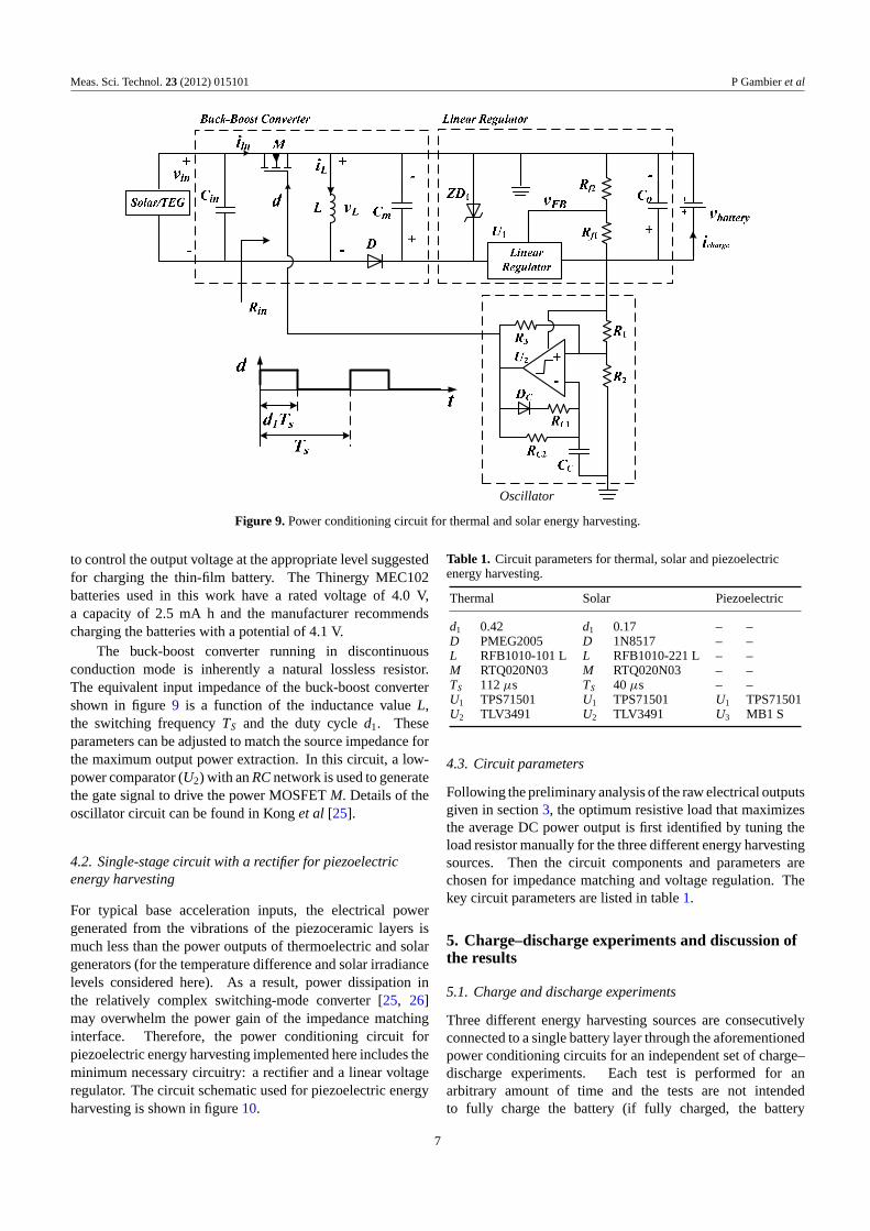
In most energy harvesting applications, the amount ofscavenged energy is too low to directly power a load; hencean intermediate storage stage is required. This typically doesnot present a problem when powering wireless sensor nodesas they usually operate on a low duty cycle, perhaps onlyneeding to operate a few times each month. In order toconvert the raw power output of the energy harvesting sourcesto a stable DC power to be stored in the thin-film battery, anefficient power conditioning circuit is indispensible for energyharvesting. In this paper, a two-stage power conditioningcircuit is implemented for both the TEG and the solar layer(s).The schematic of this two-stage circuit is shown in figure 9.The first stage of the circuit is a buck-boost converter to providean interface with matched impedance for the maximum powerextraction. The second stage of the circuit is a linear regulator
6
Meas. Sci. Technol. 23 (2012) 015101 P Gambier et al
Oscillator
Figure 9. Power conditioning circuit for thermal and solar energy harvesting.
to control the output voltage at the appropriate level suggestedfor charging the thin-film battery. The Thinergy MEC102batteries used in this work have a rated voltage of 4.0 V,a capacity of 2.5 mA h and the manufacturer recommendscharging the batteries with a potential of 4.1 V.
The buck-boost converter running in discontinuousconduction mode is inherently a natural lossless resistor.The equivalent input impedance of the buck-boost convertershown in figure 9 is a function of the inductance value L,the switching frequency TS and the duty cycle d1. Theseparameters can be adjusted to match the source impedance forthe maximum output power extraction. In this circuit, a low-power comparator (U2) with an RC network is used to generatethe gate signal to drive the power MOSFET M. Details of theoscillator circuit can be found in Kong et al [25].
4.2. Single-stage circuit with a rectifier for piezoelectricenergy harvesting
For typical base acceleration inputs, the electrical powergenerated from the vibrations of the piezoceramic layers ismuch less than the power outputs of thermoelectric and solargenerators (for the temperature difference and solar irradiancelevels considered here). As a result, power dissipation inthe relatively complex switching-mode converter [25, 26]may overwhelm the power gain of the impedance matchinginterface. Therefore, the power conditioning circuit forpiezoelectric energy harvesting implemented here includes theminimum necessary circuitry: a rectifier and a linear voltageregulator. The circuit schematic used for piezoelectric energyharvesting is shown in figure 10.
Table 1. Circuit parameters for thermal, solar and piezoelectricenergy harvesting.
Thermal Solar Piezoelectric
d1 0.42 d1 0.17 – –D PMEG2005 D 1N8517 – –L RFB1010-101 L L RFB1010-221 L – –M RTQ020N03 M RTQ020N03 – –TS 112 μs TS 40 μs – –U1 TPS71501 U1 TPS71501 U1 TPS71501U2 TLV3491 U2 TLV3491 U3 MB1 S
4.3. Circuit parameters
Following the preliminary analysis of the raw electrical outputsgiven in section 3, the optimum resistive load that maximizesthe average DC power output is first identified by tuning theload resistor manually for the three different energy harvestingsources. Then the circuit components and parameters arechosen for impedance matching and voltage regulation. Thekey circuit parameters are listed in table 1.
5. Charge–discharge experiments and discussion ofthe results
5.1. Charge and discharge experiments
Three different energy harvesting sources are consecutivelyconnected to a single battery layer through the aforementionedpower conditioning circuits for an independent set of charge–discharge experiments. Each test is performed for anarbitrary amount of time and the tests are not intendedto fully charge the battery (if fully charged, the battery
7

Meas. Sci. Technol. 23 (2012) 015101 P Gambier et al
Figure 10. Power conditioning circuit for piezoelectric energy harvesting.
(a) (b)
Voltage Voltage
Current
Current
Figure 11. (a) Current and voltage histories for charging 0.40 mA h of a single battery in 15 min using the thermoelectric power output dueto 31 ◦C temperature difference and (b) the discharge histories.
could enter a trickle charge state, thus distorting the outputpower calculations). The ambient energy levels used inthe testing (e.g. temperature differential, solar irradiance,vibration amplitude and frequency) are selected in orderto simulate realistic ambient conditions for each mode ofharvesting. In the thermal and solar energy harvestingexperiments, discharging is performed by applying a resistiveload of 1.5 k� across the battery in order to draw roughly2.5 mA of current (corresponding to a 1 C discharge rate) untila voltage level of 2.5 V is reached. In the piezoelectric energyharvesting experiment, a smaller 0.7 mA h capacity thin-filmbattery external to the self-charging structure is used (MEC-101—Infinite Power Solutions, Inc.) to better match the low-power output of the harvester such that a fair percentage ofthe battery can be charged in a reasonable amount of time.A Keithley 2611A SourceMeter is used to sink a constant1.4 mA of current (corresponding to 2 C) from the batteryduring discharging until a voltage level of 3 V is reached. Alldischarge tests are performed with the harvester disconnectedfrom the circuit in order to assess the amount of energystored in the harvesting tests. Both the voltage and currentare recorded for the thermal and solar energy harvesting testsusing a National Instruments Corporation CompactDAQ dataacquisition system with an NI 9215 analog voltage input cardwith 16-bit precision. Current measurements are made using atransimpedance amplifier to convert current into a measurablevoltage. For the piezoelectric energy harvesting test, thevoltage and current are measured directly with the KeithleySourceMeter.
For the thermal energy harvesting experiments, thetemperature difference between the hot and the cold sides is setequal to 31 ◦C. The thin-film battery receives an average DCpower of 6.6 mW for this temperature difference. The voltageand current histories for 15 min of charging time are shown infigure 11(a). The charge capacity of the battery is estimated as0.40 mA h by integrating the current measurement over time.The voltage and current histories associated with dischargingare shown in figure 11(b). The discharge capacity is obtainedfrom the area under the current curve shown in figure 11(b)as 0.37 mA h. The small difference between the calculatedcharge and discharge capacity levels is attributed to possiblecurrent leakage associated with charging.
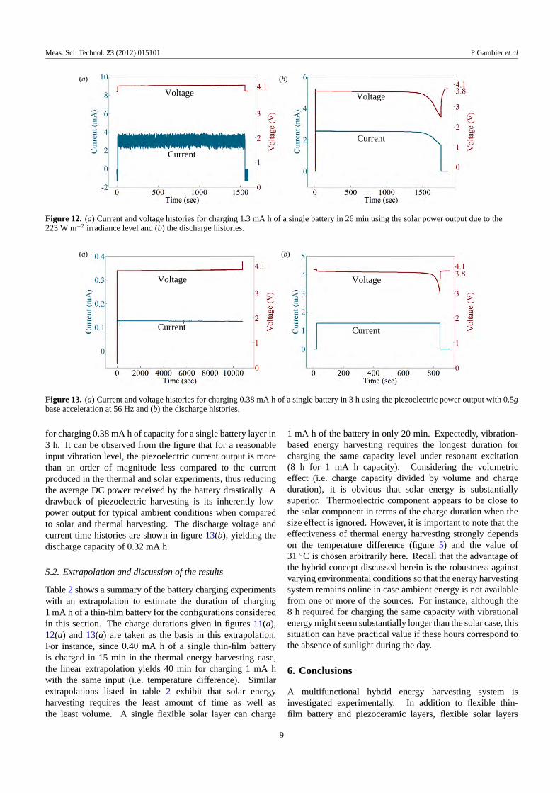
For an irradiance level of 223 W m−2, close to theaverage irradiance level found on the Earth’s surface in theUnited States [27], the battery receives 12.5 mW average DCpower from the power conditioning circuit of the solar panel.Figure 12(a) shows the voltage and current histories forcharging a thin-film battery layer with this power input for26 min, yielding a charge capacity of 1.3 mA h. The dischargetime histories are given in figure 12(b), where the dischargecapacity is 1.2 mA h.
In the presence of the nonlinear piezoelectric energyharvesting circuit (figure 10), the resonance frequency of thecantilevered self-charging structure is measured as 56.4 Hz.For harmonic base excitation with an acceleration amplitudeof 0.5g at 56.4 Hz, the battery receives an average DC power of0.49 mW. Figure 13(a) shows the voltage and current histories
8
Meas. Sci. Technol. 23 (2012) 015101 P Gambier et al
(a) (b)
Current
Current
Voltage Voltage
Figure 12. (a) Current and voltage histories for charging 1.3 mA h of a single battery in 26 min using the solar power output due to the223 W m−2 irradiance level and (b) the discharge histories.
(a)
Voltage Voltage
Current Current
(b)
Figure 13. (a) Current and voltage histories for charging 0.38 mA h of a single battery in 3 h using the piezoelectric power output with 0.5gbase acceleration at 56 Hz and (b) the discharge histories.
for charging 0.38 mA h of capacity for a single battery layer in3 h. It can be observed from the figure that for a reasonableinput vibration level, the piezoelectric current output is morethan an order of magnitude less compared to the currentproduced in the thermal and solar experiments, thus reducingthe average DC power received by the battery drastically. Adrawback of piezoelectric harvesting is its inherently low-power output for typical ambient conditions when comparedto solar and thermal harvesting. The discharge voltage andcurrent time histories are shown in figure 13(b), yielding thedischarge capacity of 0.32 mA h.
5.2. Extrapolation and discussion of the results
Table 2 shows a summary of the battery charging experimentswith an extrapolation to estimate the duration of charging1 mA h of a thin-film battery for the configurations consideredin this section. The charge durations given in figures 11(a),12(a) and 13(a) are taken as the basis in this extrapolation.For instance, since 0.40 mA h of a single thin-film batteryis charged in 15 min in the thermal energy harvesting case,the linear extrapolation yields 40 min for charging 1 mA hwith the same input (i.e. temperature difference). Similarextrapolations listed in table 2 exhibit that solar energyharvesting requires the least amount of time as well asthe least volume. A single flexible solar layer can charge
1 mA h of the battery in only 20 min. Expectedly, vibration-based energy harvesting requires the longest duration forcharging the same capacity level under resonant excitation(8 h for 1 mA h capacity). Considering the volumetriceffect (i.e. charge capacity divided by volume and chargeduration), it is obvious that solar energy is substantiallysuperior. Thermoelectric component appears to be close tothe solar component in terms of the charge duration when thesize effect is ignored. However, it is important to note that theeffectiveness of thermal energy harvesting strongly dependson the temperature difference (figure 5) and the value of31 ◦C is chosen arbitrarily here. Recall that the advantage ofthe hybrid concept discussed herein is the robustness againstvarying environmental conditions so that the energy harvestingsystem remains online in case ambient energy is not availablefrom one or more of the sources. For instance, although the8 h required for charging the same capacity with vibrationalenergy might seem substantially longer than the solar case, thissituation can have practical value if these hours correspond tothe absence of sunlight during the day.
6. Conclusions
A multifunctional hybrid energy harvesting system isinvestigated experimentally. In addition to flexible thin-film battery and piezoceramic layers, flexible solar layers
9

Meas. Sci. Technol. 23 (2012) 015101 P Gambier et al
Table 2. Extrapolated data for estimating the full charging duration of 1 mA h using thermal, solar and vibrational energy.
Thermal Solar Vibrational
Input Temperature Irradiance: Base acceleration:difference: 31 ◦C 223 W m−2 0.5g at 56.4 Hz
Dimensions 30.5 mm × 33 mm × 93 mm × 25 mm× 93 mm × 25 mm ×4.1 mm (excluding the sink) 0.178 mm (single layer) 1.5 mm (cantilevered volume)
Volume 4.13 cm3 0.414 cm3 3.49 cm3
Duration of charging 1 mA h 40 min 20 min 8 h
are combined with an aluminum substructure to constructa multilayer self-charging structural configuration that cangenerate electricity from dynamic loads and sunlight, andstore the electrical energy in its flexible thin-film battery layers.Thermoelectric power output is also used for charging the thin-film battery layers using a conventional TEG, with the eventualgoal of incorporating novel thin-film flexible thermoelectricdevices directly into the self-charging structure assembly.Nonlinear energy harvesting circuits are used for convertingthe raw DC outputs in thermal and solar energy harvesting andthe raw AC output in piezoelectric energy harvesting to thestable DC output required for charging the thin-film batterylayers. The goals of the hybrid energy harvesting conceptthat employs a composite structure with thin-film storagecomponents are to improve robustness in energy harvestingthrough the ability of harvesting multiple energy sources andmultifunctionality through the load bearing capability of theflexible structure.
The flexible composite cantilever used for solar andpiezoelectric energy harvesting with its battery layers has theapproximate dimensions of 93 mm × 25 mm × 1.5 mm underclamped conditions while the TEG has the dimensions of30.5 mm × 33 mm × 4.1 mm. For a temperature differenceof 31 ◦C between the hot and the cold sides of the TEG, thethin-film battery receives a regulated DC power of 6.6 mW,charging 0.40 mA h of capacity in 15 min. An irradiancelevel of 223 W m−2 results in 12.5 mW regulated DC powerflowing into the thin-film battery from one flexible solarpanel, charging 1.3 mA h of capacity in 26 min. For a baseacceleration input of 0.5g at 56.4 Hz, the thin-film battery layerreceives 0.49 mW regulated DC power from the piezoceramiclayers, charging 0.38 mA h of capacity in 3 h. Expectedly,the current output of piezoelectric layers is much lower thanthose of the thermoelectric and solar generators. Therefore theregulated DC power output in piezoelectric energy harvestingis more than an order of magnitude lower as compared tothose of the other two energy harvesting techniques. Theextrapolated results based on these measurements imply that1 mA h of a thin-film battery can be charged in 20 min usingsolar energy (for a solar irradiance level of 223 W m−2), in40 min using thermal energy (for a temperature differenceof 31 ◦C) and in 8 h using vibrational energy (for a baseacceleration input of 0.5g at 56.4 Hz).
Although the battery charging experiments are conductedindependently for the three energy harvesting techniquesdiscussed in this paper, it is required to combine thecircuitry for simultaneous harvesting of the thermal, solar andpiezoelectric energy. One practical difficulty in implementing
these techniques simultaneously is the amount of wiring.Using printed circuits to minimize wiring can be considered asa future research topic. Moreover, flexible electronics can becombined with the flexible self-charging structure. Recentlydeveloped fiber-based flexible TEGs can also be combinedwith the flexible self-charging structure depending on theapplication (i.e. if the hot and cold domains allow and if theother layers are not negatively affected by the temperaturelevels).
Acknowledgments
The experiments were conducted in the Center for IntelligentMaterial Systems and Structures at Virginia Tech. The authorsgratefully acknowledge the support from the US Air ForceOffice of Scientific Research under the grant F9550-06-1-0326‘Energy Harvesting and Storage Systems for Future Air ForceVehicles’ monitored by Dr B L Lee.
References
[1] Cook-Chennault K A, Thambi N and Sastry A M 2008Powering MEMS portable devices—a review ofnon-regenerative and regenerative power supply systemswith emphasis on piezoelectric energy harvesting systemsSmart Mater. Struct. 17 043001
[2] Miles R W, Hynes K M and Forbes I 2005 Photovoltaic solarcells: an overview of state-of-the-art cell development andenvironmental issues Prog. Cryst. Growth Charact. Mater.51 1–42
[3] Chen M, Lu S S and Liao B 2005 On the figure of merit ofthermoelectric generators ASME J. Energy Resour. Technol.127 37–41
[4] Priya S, Chen C T, Fye D and Zahnd J 2005 Piezoelectricwindmill: a novel solution to remote sensing Japan. J. Appl.Phys. 44 L104–7
[5] Erturk A, Vieira W G R, De Marqui C Jr and Inman D J 2010On the energy harvesting potential of piezoaeroelasticsystems Appl. Phys. Lett. 96 184103
[6] Beeby S P, Tudor M J and White N M 2006 Energy harvestingvibration sources for microsystems applications Meas. Sci.Technol. 17 R175–95
[7] Roundy S and Wright P K 2004 A piezoelectric vibrationbased generator for wireless electronics Smart Mater.Struct. 13 1131–44
[8] Glynne-Jones P, Tudor M J, Beeby S P and White N M 2004An electromagnetic, vibration-powered generator forintelligent sensor systems Sensors Actuators A 110 344–9
[9] Mitcheson P, Miao P, Start B, Yeatman E, Holmes Aand Green T 2004 MEMS electrostatic micro-powergenerator for low frequency operation Sensors Actuators A115 523–9
10

Meas. Sci. Technol. 23 (2012) 015101 P Gambier et al
[10] Wang L and Yuan F G 2008 Vibration energy harvesting bymagnetostrictive material Smart Mater. Struct. 17 045009
[11] Anton S R and Sodano H A 2007 A review of powerharvesting using piezoelectric materials (2003–2006) SmartMater. Struct. 16 R1–21
[12] Erturk A and Inman D J 2011 Piezoelectric Energy Harvesting(Chichester: Wiley)
[13] Christodoulou L and Venables J D 2003 Multifunctionalmaterial systems: the first generation J. Miner. Met. Mater.Soc. 55 39–45
[14] Aglietti G S, Schwingshackl C W and Roberts S C 2007Multifunctional structure technologies for satelliteapplications Shock Vib. Dig. 39 381–91
[15] Thomas J P and Qidwai M A 2005 The design and applicationof multifunctional structure-battery materials systemsJ. Miner. Met. Mater. Soc. 57 18–24
[16] Dong S, Zhai J, Li J F, Viehland D and Priya S 2008Multimodal system for harvesting magnetic and mechanicalenergy Appl. Phys. Lett. 93 103511
[17] Toreyin H, Topal E and Kulah H 2010 A multi-source micropower generator employing thermal and vibration energyharvesting Procedia Eng. 5 1176–9
[18] Anton S R, Erturk A and Inman D J 2010 Multifunctionalself-charging structures using piezoceramics and thin-filmbatteries Smart Mater. Struct. 19 115021
[19] Mayer P M and Ram R J 2006 Optimization of heat sinklimited thermoelectric generators Nanoscale MicroscaleThermophys. Eng. 10 143–55
[20] Cobble M H 1995 Calculations of generator performance CRCHandbook of Thermoelectrics (New York: CRC Press)chapter 39
[21] Erturk A and Inman D J 2009 An experimentally validatedbimorph cantilever model for piezoelectric energyharvesting from base excitations Smart Mater. Struct.18 025009
[22] Shu Y C and Lien I C 2006 Analysis of power outputs forpiezoelectric energy harvesting systems Smart Mater.Struct. 15 1499–502
[23] Stanton S C, Erturk A, Mann B P and Inman D J 2010Nonlinear piezoelectricity in electroelastic energyharvesters: modeling and experimental identificationJ. Appl. Phys. 108 074903
[24] Stanton S C, Erturk A, Mann B P and Inman D J 2010Resonant manifestation of intrinsic nonlinearity withinelectroelastic micropower generators Appl. Phys. Lett.97 254101
[25] Kong N, Ha D S, Erturk A and Inman D J 2010 Resistiveimpedance matching circuit for piezoelectric energyharvesting J. Intell. Mater. Syst. Struct. 21 1293–302
[26] Lallart M and Guyomar D 2008 An optimized self-poweredswitching circuit for non-linear energy harvestingwith low voltage output Smart Mater. Struct.17 035030
[27] Thomas J P, Qidwai M A and Kellogg J C 2006 Energyscavenging for small-scale unmanned systems J. PowerSources 159 1494–509
11