pier 68-70 shipyard facility condition survey marine ... rfp/shipyard site...existing marine...
TRANSCRIPT

2185 North California Blvd, Suite 500 Walnut Creek, CA 94596
July 21, 2017 Job: 9590-06
Pier 68-70 Shipyard Facility Condition Survey Marine Structures
Prepared for:
Prepared by:
_ A Joint Venture

Pier 68-70 | Port of San Francisco
_
This page intentionally blank

Pier 68-70 | Port of San Francisco
_ 3
Table of Contents
1. Executive Summary .............................................................................................................................................. 5
2. Introduction............................................................................................................................................................ 7
2.1 Purpose and Scope ...................................................................................................................................... 7
2.2 Methodology ................................................................................................................................................. 7
2.3 Description of Structures .............................................................................................................................. 8
High Water Platform .............................................................................................................................................. 8
Mooring Dolphins: ................................................................................................................................................. 8
3. Structure Condition ................................................................................................................................................ 9
3.1 Wharf 3: ...................................................................................................................................................... 10
3.2 Wharf 4: ...................................................................................................................................................... 12
3.3 High Water Platform ................................................................................................................................... 14
Area 1: ................................................................................................................................................................. 14
Area 2: ................................................................................................................................................................. 16
Areas 5 & 6:......................................................................................................................................................... 18
Area 7: ................................................................................................................................................................. 20
Area 8: ................................................................................................................................................................. 22
Area 9: ................................................................................................................................................................. 23
Steel Bridge: ........................................................................................................................................................ 25
3.4 Mooring Dolphins: ....................................................................................................................................... 26
4. Conceptual Cost Estimate & Repair Recomnedations ........................................................................................ 28
Appendices A. Pier 68-70 Summary Inspection Figures / Available Reference Drawing

Pier 68-70 | Port of San Francisco
_ 4
Figures
Figure 1 - Pier 68-70 Shipyard Marine Structures .......................................................................................................... 5 Figure 2 – Structures and Subareas .............................................................................................................................. 7 Figure 3 - Typical Condition Pile, Pile cap, Beam ........................................................................................................ 10 Figure 4 – Crack in Protective Concrete Over Steel Girder, Indicating Corrosion ........................................................ 11 Figure 5 - Spalled Duct Bank and Exposed Conduit ................................................................................................... 11 Figure 6 – Typical Deck Condition ............................................................................................................................... 11 Figure 7 –Spall on Deck Edges .................................................................................................................................... 11 Figure 8 - Typical Conditions Beams, Piles, Pile caps ................................................................................................. 12 Figure 9 –Crack on Pile Cap ........................................................................................................................................ 13 Figure 10 – Cracks and Corrosion on Beams ............................................................................................................. 13 Figure 11 – Cracks on Beam ....................................................................................................................................... 13 Figure 12 –Spall on Deck Edge ................................................................................................................................... 13 Figure 13 - Typical Condition of Beams and Piles ....................................................................................................... 14 Figure 14 – Exposed Steel Pile and Corrosion ............................................................................................................ 15 Figure 15 –Spall on Overhead Deck ............................................................................................................................ 15 Figure 16 –Spall on Bulkhead Column and Beam ....................................................................................................... 15 Figure 17 - Typical Condition of Beams and Piles ....................................................................................................... 16 Figure 18 – Cracked Pile Cap ...................................................................................................................................... 17 Figure 19 – crack on Beams ........................................................................................................................................ 17 Figure 20 – Typical Beams and Pile Condition ............................................................................................................ 18 Figure 21 – Spall and Crack on Beams ....................................................................................................................... 19 Figure 22 – Spall on Deck & Corrosion Stains ............................................................................................................. 19 Figure 23 – Typical Condition of Piles, Pile Caps, Beams & Deck .............................................................................. 20 Figure 24 – crack on deck ............................................................................................................................................ 21 Figure 25 – beam spall and section loss ...................................................................................................................... 21 Figure 26 - Typical Pile and Deck Condition ................................................................................................................ 22 Figure 27 - Settlement of Piles ..................................................................................................................................... 22 Figure 28 – Typical Conditon of Piles , Beams & Deck ............................................................................................... 23 Figure 29 – Spallson Beam and Pile Cap .................................................................................................................... 24 Figure 30 – Crack on Pile Cap ..................................................................................................................................... 24 Figure 31 – Spall on Beam ........................................................................................................................................... 24 Figure 32 – Spall on Deck ............................................................................................................................................ 24 Figure 33 - Typical Condition of Steel Bridge Underside ............................................................................................. 25 Figure 34 – Loss of Protective Coating on Bridge, Spalled Pile Cap ........................................................................... 25 Figure 35 – Minor Corrosion and Loss of Protective Coating ....................................................................................... 25 Figure 36 - Typical Piles & Pile Cap ............................................................................................................................. 26 Figure 37 - Spall on Edge of Pile Cap .......................................................................................................................... 27 Figure 38 - Crack and spall on Pile Cap Corner .......................................................................................................... 27 Figure 39 - Crack and Spalling on Dolphin................................................................................................................... 27

Pier 68-70 | Port of San Francisco
_ 5
1. EXECUTIVE SUMMARY The purpose of this report is to provide an assessment of the overall condition of the existing marine structures at Pier 68-70 Shipyard within the Port of San Francisco (POSF) to disclose the information to ship repair operators interested in leasing the facility. The Facility includes buildings, site infrastructures, and electrical power systems, and marine structures. This report includes information pertaining to structures shown on Figure 1 and includes the following:
Wharf 3 (Pier 3), is a reinforced concrete structure and structural steel supported by steel H piles. The existing structure was constructed in 1967.
Wharf 4 (Pier 4), is a reinforced concrete structure and structural steel supported by steel pipe piles. The Existing structure was constructed in 1957.
High Water Platform (HWP) is a reinforced concrete structure which connects the two wharves together. This platform was built in multiple phases in between 1950 to 1970, with minor repairs and addition of a steel bridge in 1999.
Figure 1 - Pier 68-70 Shipyard Marine Structures
Information from previous evaluations was made available by the Port of San Francisco (POSF), and were reviewed to inform this effort including:
Rapid Structural Assessment (RSA) report, POSF, 2017 Report by Triton Engineers, 2015. Dry Dock No.2 Underwater Condition Assessment

Pier 68-70 | Port of San Francisco
_ 6
Moffatt & Nichol, performed an above-water survey on June 26th and 27th 2017, from a boat to document locations of damage and deterioration of the marine structures. The observed damages are cracks, spalls, delamination of concrete, exposed reinforcing bars and corrosion of steel members.
Generally, Wharf 3 and Wharf 4 are in good condition. The most noteworthy damage is at steel beams encased in concrete supporting the crane rails. The concrete encasement has cracks and is partially delaminated close to the soffit, indicating corrosion has developed on the bottom flange of the steel beams. Conceptual repair is to remove the soffit concrete, remove corrosion, clean the steel beam bottom flange, and apply corrosion-resisting concrete patch. The estimated cost for Wharf 3 and Wharf 4 repair is $475,000.
The HWP is in poor to good condition. For the most part, the platform is in good condition but there are sections in between wharves 3 and 4 in bad condition with numerous reinforced concrete beams with exposed and heavily corroded reinforcing bars at the soffit of the beams. Conceptual repair is to remove all unsound concrete at the bottom (including sides) of the beam, removing all unsound reinforcing bars, adding reinforcing bars, forming and pumping new concrete at the bottom of the beams. The estimated cost for this repair is $810,000.
The piles supporting the marine structures are either steel H-piles or steel pipe piles encased in wire mesh and shotcrete. Wharf 3 is supported by steel H-piles, and Wharf 4 is supported by steel pipe piles. The HWP is generally supported by steel pipe piles except for areas on the east and west ends, which are supported by steel H-piles. The piles appear to be in good condition. It was indicated that the piles had an electric-induced corrosion protection, but this corrosion protection system has been out of service for approximately 15 years. It is recommended to perform a detailed inspection for the steel piles to determine thickness of steel, extent of any corrosion, or steel cross-sectional area loss. Since the last inspection was conducted in 2015 by Triton Engineers, it is recommended that the next inspection should be done within the next 3 years – and periodically every five (5) years thereafter. This recommendation is based on ASCE manual No. 130 (2015) “Waterfront Facilities Inspection and Assessment” recommended maximum interval between routine inspections.

Pier 68-70 | Port of San Francisco
_ 7
2. INTRODUCTION Piers, wharves and marine structures along the San Francisco waterfront vary by era of construction, physical state, and prospective maintenance and repair costs. To allow the POSF to disclose the condition of Pier 68-70’s marine structures to the prospective tenants, Moffatt & Nichol has prepared this structural condition assessment of the existing marine structures, recommended repairs, and a conceptual level cost estimate.
2.1 Purpose and Scope The purpose of this report is to provide a condition assessment of the marine structures at pier 68-70 structures. This evaluation involves documentation of deteriorated structural elements, required or recommended repairs, and an approximate cost estimate of said repairs. Moffatt & Nichol personnel investigated the three main marine structures: Wharf 3, Wharf 4, and the east west connection pier (High Water Platform) which are known collectively as Pier 68-70 to evaluate their current conditions, and provide an approximate range of repair cost.
2.2 Methodology Moffatt and Nichol conducted an above-water inspection of the three main marine structures: Wharf 3, Wharf 4 and the High Water Platform (HWP) via a boat during low tide on 6/26/2017 (-1.5 ft.) and 6/27/2017 (-1.2 ft.). Engineers photographed and documented visible defects. Drawings provided by the POSF were used to determine beam and pile locations throughout the inspection. The RSA report from POSF and the reports by Triton Engineers were also utilized as references to locate deteriorating sections of the structures. The 2015 Inspection Report by Triton Engineers divides the HWP into 7 sub areas, with the same area divisions used in this report, as shown in Figure 2. No below water level inspection was conducted.
Recommended repairs for the marine structures are based off the results from the general condition assessment with approximate repair quantities/locations. In Table 1. the conditions have been ranked from Good ( no visible damages) to Critical (very advanced deterioration) in accordance with ASCE 101.
Figure 2 – Structures and Subareas

Pier 68-70 | Port of San Francisco
_ 8
2.3 Description of Structures Pier 68-70 has been used as a shipyard since the early 20th century. The wharves and the docks were used to conduct ship repair, and the buildings and other facilities were used as storage or to manufacture required components for the ship repairs. The structures were designed to support heavy industrial loads. The description of the marine structures follows.
Wharf 3 Wharf 3 was originally constructed in 1945, but it was relocated to its present location in 1967. Wharf 3 has a width of 44 ft. and extends north from HWP into the San Francisco Bay by approximately 700 ft. The Wharf’s surface area is approximately 31,000 square feet (sqft.). The wharf includes reinforced concrete decking supported on 421 steel H-Piles (14H-73) at 30 ft. bent spacing.
Wharf 3 includes two 35-ton rail mounted boom cranes (currently out of service). The crane rails are supported by steel I beams embedded in the concrete deck, 24 ft. apart. Wharf 3 includes the necessary infrastructure to service large vessels. Fresh water, salt water, compressed air service lines, as well as electricity distribution centers are positioned at regular intervals along the wharf length.
Wharf 4 Wharf 4 was constructed in 1957 with no major changes since. Wharf 4 has a width of 44 ft. and extends north from HWP into the San Francisco Bay approximately 650 ft. The wharf surface area is approximately 29,000 sqft. The wharf includes reinforced concrete decking supported on 532 steel pipe piles (18 in-diameter) at 18 ft. bent spacing.
Wharf 4 includes two 35 ton rail mounted boom cranes (currently out of service). The crane rails appear to be supported by steel I beams embedded in in the concrete deck, 24 ft. apart. Pier 4 includes the necessary infrastructure for servicing large vessels. Fresh water, salt water, compressed air service lines, as well as electricity distribution center are positioned at regular intervals along the wharfs length.
High Water Platform The HWP was constructed in multiple phases from the 1950s through 1970. The HWP provides access to Wharf 3, Wharf 4 and the Dry Dock No.2.The platform runs parallel to the shoreline in east-west direction for approximately 1,000 ft. with an average width of 80 ft. The platforms surface area is approximately 115,000 sqft. The HWP has reinforced concrete deck, supported by steel H-Piles (14H-73) and steel pipe piles (18 in-diameter) totaling 679 piles. The HWP is divided into 7 Subareas.
Area 1 (Steel H - Piles) Area 2 (Steel Pipe Piles) Area 5 & 6 (Steel Pipe Piles) Area 7 (Steel Pipe Piles) Area 8 (Concrete Caissons) Area 9 (Steel H – Piles)
Subarea 8 has been red-tagged since the early 2000’s. A steel bridge has been added between sub area 7 and 9, in 1999 as a replacement for a collapsed section of platform
Mooring Dolphins: There are four mooring Dolphins for Dry Dock No.2. Each dolphin is a reinforced concrete platform supported by steel pipe piles. The mooring system consists of mooring keepers anchored to the east face of each dolphin that hold vertical rails welded to the side of the drydock.

Pier 68-70 | Port of San Francisco
_ 9
3. STRUCTURE CONDITION The general condition of the marine structures was assessed by observing representative elements with documentation of approximate locations of individual defects. The field work, performed over two days, included a visual inspection of accessible structural members as follows:
- June 26, 2017 superstructure of Wharf 3, Wharf 4, HWP Areas 5,6,7,9 were observed below deck from boat at low tide.
- June 27, 2017 substructure of HWP Area 1, 2, 8 and mooring dolphins were observed below deck from boat at low tide.
Drawings with defects noted, have been included in Appendix A. No underwater inspection has been conducted to determine the structural integrity of the piles below water level. Table 1. Summary of Marine Structure Condition based on ASCE 101
Element Condition Linear ft./Surface Area Requiring Repair
Wharf 3 Piles Satisfactory Not Applicable(N/A)
Beams Fair 460 (lf.) Deck Satisfactory 40 (sqft.)
Wharf 4 Piles Satisfactory N/A
Beams Fair 125 (lf.) Deck Satisfactory 455 (sqft.)
HWP – Area 1 Piles Satisfactory / Fair N/A
Beams Satisfactory 35 (lf.) Deck Fair / Poor 675 (sqft.)
HWP - Area 2 Piles Satisfactory N/A
Beams Satisfactory / Fair 130 (lf.) Deck Satisfactory 45 (sqft.)
HWP – Areas 5 & 6 Piles Satisfactory N/A
Beams Fair 145 (lf.) Deck Satisfactory / Fair 45 (sqft.)
HWP Area 7 Piles Satisfactory N/A
Beams Poor 430 (lf.) Deck Fair 250 (sqft.)
HWP – Area 8 Piles Red-Tagged N/A
Beams Red-Tagged N/A Deck Red-Tagged N/A
HWP – Area 9 Piles Satisfactory N/A
Beams Satisfactory / Fair 135 (lf.) Deck Satisfactory 130 (sqft.)
Pier 68-70 | Port of San Francisco
_ 10
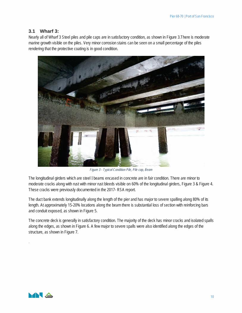
3.1 Wharf 3: Nearly all of Wharf 3 Steel piles and pile caps are in satisfactory condition, as shown in Figure 3.There is moderate marine growth visible on the piles. Very minor corrosion stains can be seen on a small percentage of the piles rendering that the protective coating is in good condition.
Figure 3 - Typical Condition Pile, Pile cap, Beam
The longitudinal girders which are steel I beams encased in concrete are in fair condition. There are minor to moderate cracks along with rust with minor rust bleeds visible on 60% of the longitudinal girders, Figure 3 & Figure 4. These cracks were previously documented in the 2017- RSA report.
The duct bank extends longitudinally along the length of the pier and has major to severe spalling along 80% of its length. At approximately 15-20% locations along the beam there is substantial loss of section with reinforcing bars and conduit exposed, as shown in Figure 5.
The concrete deck is generally in satisfactory condition. The majority of the deck has minor cracks and isolated spalls along the edges, as shown in Figure 6. A few major to severe spalls were also identified along the edges of the structure, as shown in Figure 7.
.

Pier 68-70 | Port of San Francisco
_ 11
Figure 4 – Crack in Protective Concrete Over Steel Girder, Indicating Corrosion
Figure 5 - Spalled Duct Bank and Exposed Conduit
Figure 6 – Typical Deck Condition
Figure 7 –Spall on Deck Edges

Pier 68-70 | Port of San Francisco
_ 12
3.2 Wharf 4: Nearly all of the steel Piles are in satisfactory condition as shown in Figure 8. There are major spalls and cracks (Figure 9) visible on approximately 5-10% of pile caps. There are moderate marine growths visible on the piles and minor rust stains can be seen. The protective shotcrete coating of the piles is in generally good condition with minor vertical cracks visible on approximately 5% of piles.
Figure 8 - Typical Conditions Beams, Piles, Pile caps
The longitudinal steel I beams encased in concrete are in fair condition. The crane rail girders have minor to moderate cracks with corrosion stains visible along approximately 80-90% of the wharfs length. The cracks and corrosion stains are shown in Figure 10 and Figure 11. These cracks are documented in the 2017- RSA report.
The concrete deck is generally in satisfactory condition. There are moderate to major spalls visible at the east side of the wharf deck, as shown in Figure 12. The west side of the deck could not be inspected due to the positioning of the dry dock Eureka on the west side of the pier.

Pier 68-70 | Port of San Francisco
_ 13
Figure 9 –Crack on Pile Cap
Figure 10 – Cracks and Corrosion on Beams
Figure 11 – Cracks on Beam
Figure 12 –Spall on Deck Edge

Pier 68-70 | Port of San Francisco
_ 14
3.3 High Water Platform
Area 1: Area 1 is generally in fair condition, as shown in Figure 13. Majority of the steel piles have protective shotcrete coating in satisfactory to fair condition. Approximately 20 - 40% of the steel piles have deteriorated coating, exposed steel and visible corrosion stains at the base as shown in Figure 14. The inspection of this area was done by foot.
Figure 13 - Typical Condition of Beams and Piles
The bulkhead on the land side and the underside of the deck above the wall are in poor condition with severe spalling and exposed reinforcing bars through approximately 90% of the length of the structure, as shown in Figure 15 & Figure 16. The rest of the deck spanning between the two rows of piles is in satisfactory condition with no damage to minor deteriorations visible.
The majority of the beams are in satisfactory condition with very minimal deterioration and cracks.

Pier 68-70 | Port of San Francisco
_ 15
Figure 14 – Exposed Steel Pile and Corrosion
Figure 15 –Spall on Overhead Deck
Figure 16 –Spall on Bulkhead Column and Beam

Pier 68-70 | Port of San Francisco
_ 16
Area 2: Area 2 is in generally satisfactory condition. Almost all of the steel pipe piles are in good condition with minimal visible deterioration as shown in Figure 17. Several pile caps have minor to moderate cracks (Figure 18).
Figure 17 - Typical Condition of Beams and Piles
The reinforced concrete beams spanning between the pile caps are in satisfactory condition. However, approximately 10-15% of the beams have moderate to major cracks extending their full length, as shown in Figure 19.
The concrete deck is in good condition with little to no deterioration visible.

Pier 68-70 | Port of San Francisco
_ 17
Figure 18 – Cracked Pile Cap
Figure 19 – crack on Beams

Pier 68-70 | Port of San Francisco
_ 18
Areas 5 & 6: Area 5 is in satisfactory condition with minor deteriorations and area 6 is in fair condition with a multiple deteriorations and spall observed at the west edge of the structure.
Almost all of the steel pipe piles are in satisfactory condition with minimal visible deterioration as shown in Figure 20. Pile caps are in satisfactory condition with minor cracks visible at few isolated locations.
Figure 20 – Typical Beams and Pile Condition
The reinforced concrete beams spanning between the pile caps are in fair condition. Approximately 25-30% of the beams in Area 6 have severe spalls spanning the full length of the beams along with moderate to major cracks. As shown in Figure 21, many of the beams have substantial section loss with exposed reinforcing bars.
The reinforced concrete deck in Area 5 also has isolated minor to moderate spalls at a few locations, the spalls spread approximately 10-15% of the slab areas, as shown in Figure 22

Pier 68-70 | Port of San Francisco
_ 19
Figure 21 – Spall and Crack on Beams
Figure 22 – Spall on Deck & Corrosion Stains

Pier 68-70 | Port of San Francisco
_ 20
Area 7: Area 7 has major deterioration throughout the structure and is in poor condition as shown in Figure 23.
The majority of the steel pipe piles are in good condition with minor cracks and minor corrosion stains. The protective shotcrete coating is intact and in good condition and shown in Figure 23. Pile caps are generally in satisfactory conditions with a few minor isolated spalls.
Figure 23 – Typical Condition of Piles, Pile Caps, Beams & Deck
The beams in Area 7 are in poor condition. Approximately 60-80% of the reinforced concrete beams within this subarea have major to severe spalling and cracks. As shown in f Figure 24 and Figure 25 there is substantial loss of section and exposed reinforcing bars extending to almost the full length of the beams.
There are numerous moderate cracks in the concrete deck distributed approximately throughout 40-70% of the area.
Area 7 is an essential access way to Area 9 and Dry Dock No. 2. Due to its level of deterioration and its significance in keeping the pier operational, urgent repairs are recommended for this area, particularly the beams and the deck slabs.

Pier 68-70 | Port of San Francisco
_ 21
Figure 24 – crack on deck
Figure 25 – beam spall and section loss

Pier 68-70 | Port of San Francisco
_ 22
Area 8: Area 8 has been red tagged for many years due to excessive settlement of the caissons. The majority of the concrete caisson and caps have major cracks as shown in Figure 26.The girder has also suffered major deterioration due to the settlement. Level of settlement compared to the adjacent area 6 can be viewed in Figure 27.
This area has foundation problems and to repair would mean complete rebuild of the structure. The area could be simply demolished and not rebuilt – since there seems to be no use for the area, and access to the Drydock #2 is still provided by the steel bridge. The estimated cost to demolish Area 8 is approximately $630,000. This cost includes the removal of the concrete deck and the caisson caps. The caissons could be left in-place.
Figure 26 - Typical Pile and Deck Condition
Figure 27 - Settlement of Piles
Area 6
Area 8

Pier 68-70 | Port of San Francisco
_ 23
Area 9: Area 9 is in satisfactory condition. Nearly all the Steel piles are in satisfactory condition with protective coating intact with minor corrosion stains and minor cracks on approximately 10-20% of the piles, Figure 28. Nearly all pile caps are in satisfactory / Fair condition however approximately 15-20 % of pile caps have moderate cracks and spalls as shown in Figure 29 and Figure 30.
Figure 28 – Typical Conditon of Piles , Beams & Deck
The Beams are in satisfactory / fair condition. Approximately 15-20% of the beams have moderate cracks. Few isolated spalls were also observed on few beams. As shown in Figure 31 some beams have exposed reinforcing bars and deteriorating reinforcements
The concrete deck is in satisfactory condition throughout. Two spalls occurring on rectangular section of the deck have severe deterioration and exposed reinforcements as shown in Figure 32.

Pier 68-70 | Port of San Francisco
_ 24
Figure 29 – Spallson Beam and Pile Cap
Figure 30 – Crack on Pile Cap
Figure 31 – Spall on Beam
Figure 32 – Spall on Deck

Pier 68-70 | Port of San Francisco
_ 25
Steel Bridge: The steel Bridge spanning over the collapsed area between area 7 and 9 is in satisfactory condition. Based on available information the steel bridge was installed in 1999. As shown in the figures below, there are multiple areas where the protective coating has deteriorated and minor corrosion is visible. The pile caps adjacent to the steel bridge as shown in Figure 34 and Figure 35 have major spalls and corroded reinforcing bars.
Figure 33 - Typical Condition of Steel Bridge Underside
Figure 34 – Loss of Protective Coating on Bridge, Spalled Pile Cap
Figure 35 – Minor Corrosion and Loss of Protective Coating

Pier 68-70 | Port of San Francisco
_ 26
3.4 Mooring Dolphins: The Mooring Dolphins are in generally satisfactory conditions. However, spalls were observed at few edges of the pile caps, as shown in Figure 37 and Figure 38. Moderate cracks as shown in Figure 39 were also observed on all the dolphins.
We have reviewed the Draft Report by Collins Engineers dated July 14, 2017 “Drydock 2 Underwater Condition Assessment” which included the steel pipe piles for the four mooring dolphins. The ultrasonic measurements for 8 of the 62 piles indicate an average of approximately 13 percent loss in the pile wall thickness originally 1/2-inch thick. The recommendation in the report that no immediate repairs are needed and regularly scheduled inspection be done seems reasonable.
Figure 36 - Typical Piles & Pile Cap

Pier 68-70 | Port of San Francisco
_ 27
Figure 37 - Spall on Edge of Pile Cap
Figure 38 - Crack and spall on Pile Cap Corner
Figure 39 - Crack and Spalling on Dolphin

Pier 68-70 | Port of San Francisco
_ 28
4. CONCEPTUAL COST ESTIMATE & REPAIR RECOMNEDATIONS This estimate shall be considered a level Class 4 estimate (based on AACE Construction Cost Estimate accuracy range) which has an expected range of -15% to -30% (lower bound) to +20% to +50% (upper bound). This cost does not include design, administration and environmental permitting costs.
Table 2 – conceptual cost estimate for each sub area.
Sub Area Element Condition Unit Price of Repair (per
LF. or per Sq. ft.)
Linear ft./Surface Area Requiring Repair Total Price
Wharf 3
Piles Satisfactory Not Applicable(N/A) Not Applicable(N/A) Not Applicable(N/A)
Beams Fair 600 460 (LF.) $ 276,000.00
Deck Satisfactory 250 40 (Sq. Ft.) $ 10,000.00
Wharf 4
Piles Satisfactory N/A N/A N/A
Beams Fair 600 125 (LF.) $ 75,000.00
Deck Satisfactory 250 455 (Sq. Ft.) $ 113,750.00
HWP – Area 1 Piles Satisfactory / Fair N/A N/A N/A
Beams Satisfactory 600 35 (LF.) $ 21,000.00 Deck Fair / Poor 250 675 (Sq. Ft.) $ 168,750.00
HWP - Area 2 Piles Satisfactory N/A N/A N/A Beams Satisfactory / Fair 600 130 (LF.) $ 78,000.00 Deck Satisfactory 250 45 (Sq. Ft.) $ 11,250.00
HWP – Areas 5 & 6
Piles Satisfactory N/A N/A N/A
Beams Fair 600 145 (LF.) $ 87,000.00 Deck Satisfactory / Fair 250 45 (Sq. Ft.) $ 11,250.00
HWP Area 7
Piles Satisfactory N/A N/A N/A
Beams Poor 600 430 (LF.) $ 258,000.00
Deck Fair 250 250 (Sq. Ft.) $ 62,500.00
HWP – Area 8 Piles Red-Tagged N/A N/A N/A
Beams Red-Tagged N/A N/A N/A Deck Red-Tagged N/A N/A N/A
HWP – Area 9
Piles Satisfactory N/A N/A N/A
Beams Satisfactory / Fair 600 135 (LF.) $ 81,000.00
Deck Satisfactory 250 130 (Sq. Ft.) $ 32,500.00
Total cost $ 1,286,000.00

Pier 68-70 | Port of San Francisco
_ 29
The cost estimate for demolition of Area 8 can be view in Table 3. This estimate includes the removal of the concrete deck and the caisson caps. The removal of caissons are not included in the estimate.
Table 3 - Area 8 Demolition Cost
Sub Area 8 – HWP Surface Area (Sq ft.) Unit Price for Demolition $/Sq. ft. Total Price
Red Tagged - Demolition 5,300 95 $ 630,000

Pier 68-70 | Port of San Francisco
_ 30
APPENDIX A - Pier Summary Inspection Figures / Available
Reference Drawings

Spalled Duct Bank Spalled Duct Bank &Exposed Conduit
Spalled Deck
SeriousPoorSatisfactory / Fair

Pile Cap Spall and Crack Corrosion Stains on Deck and Beam
Spalled Pile CapCracks on Beams
Serious
Poor
Satisfactory / Fair

Typical Deck , Beam andPile Cap condition
Typical Condition Major Crack on Pile Cap
Wharf 4

Spalled Deck and Column
Deck Spall
Corrosion on Piles
Typical Condition of Deck, Beam, Piles
Serious
Poor
Satisfactory / Fair

Major Crack on Pile Cap
Typical Conditon of Piles,Pile Caps, Decks
Exposed Piles
Crack on Beam
Serious
Satisfactory / Fair
Poor

Cracked Pile Cap
Sever Spalled Beams
Deck Condition
Beam, Pile Cap and Deck condition
Serious
Satisfactory / Fair
Poor

Spalled Beams
Typical Deck , Beam, Pile CapCondition
Typical Deck , Beam, Pile CapCondition
Serious
Satisfactory / Fair
Poor

Severe Spall on Beam
Typical Condition of Deck , BeamPile
Spalled Beam & Pile Cap
Satisfactory / Fair
Poor
Serious