pico protector pg-06 & pk-06 series - the siemon...
TRANSCRIPT

Installation Instructions
PICO PROTECTOR®
PG-06 & PK-06Series
LISTED 95P5 SIGNAL CIRCUIT PROTECTOR
2
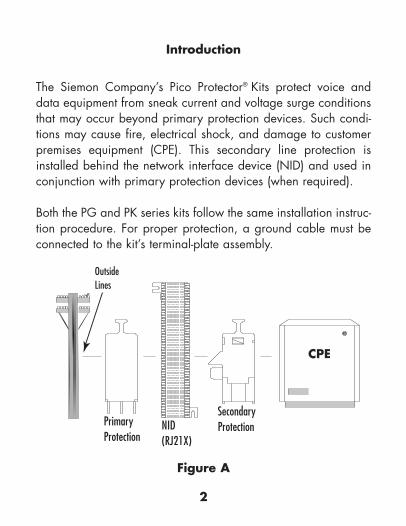
Introduction
The Siemon Company’s Pico Protector® Kits protect voice anddata equipment from sneak current and voltage surge conditionsthat may occur beyond primary protection devices. Such condi-tions may cause fire, electrical shock, and damage to customerpremises equipment (CPE). This secondary line protection isinstalled behind the network interface device (NID) and used inconjunction with primary protection devices (when required).
Both the PG and PK series kits follow the same installation instruc-tion procedure. For proper protection, a ground cable must beconnected to the kit’s terminal-plate assembly.
OutsideLines
Primary Protection
NID(RJ21X)
SecondaryProtection
Figure A
CPE

3
Safety Considerations
For UL 497A compliance the PICO Protector® is installed in a ULlisted type 1 enclosure with UL listed Siemon Company S66Mseries connecting blocks. The installation is to be in accordancewith National Electric Code requirements and local authorities.Connecting blocks may be purchased separately or in kit formwith grounding hardware.
Pico Protector ground kits and protector modules arepurchased separately.
Protectors must be installed and maintained bytrained service personnel only.
WARNING:This product may only be installed on the protectedside of the primary building entrance protector (whenpresent). These instruction procedures must be fol-lowed explicitly to avoid safety hazards to equip-ment, plant and personnel.
TO NID
FUSES
Figure B(Pico Circuit) TO CPE
SOLID STATE SILICON TRANSISTOR
4
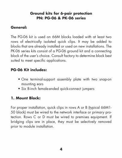
Ground kits for 6-pair protection PN: PG-06 & PK-06 series
General:
The PG-06 kit is used on 66M blocks loaded with at least tworows of electrically isolated quick clips. It may be added toblocks that are already installed or used on new installations. ThePK-06 series kits consist of a PG-06 ground kit and a connectingblock of the user’s choice. Consult factory to determine block bestsuited to meet specific applications.
PG-06 Kit includes:
• One terminal-support assembly plate with two snap-onmounting ears
• Six 8-inch female-ended quick-connect jumpers
1. Mount Block:
For proper installation, quick clips in rows A or B (typical 66M1-50 block) must be wired to the network interface or primary pro-tection. Rows C or D must be wired to premises equipment. Ifbridging clips are in place, they must be selectively removedprior to module installation.
5
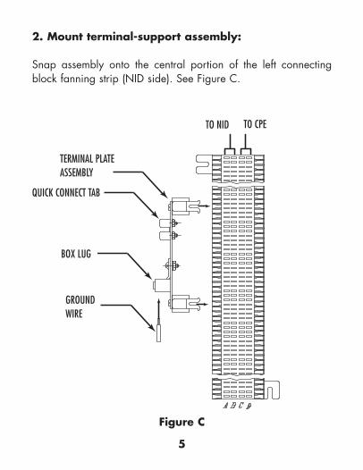
2. Mount terminal-support assembly:
Snap assembly onto the central portion of the left connectingblock fanning strip (NID side). See Figure C.
Figure C
TERMINAL PLATEASSEMBLY
QUICK CONNECT TAB
BOX LUG
GROUNDWIRE
TO NID TO CPE

6
3. Attach ground wire:
Connect #6-#12 ground wire (not included) to terminal-supportassembly by sliding the ground wire into the box lug on the plateand tightening the screw (slotted screw driver required). SeeFigure C.
4. Install Modules:
Push protection modules onto quick clip rows B and C of theblock. Important: Ground tab must face the side of theblock wired to the NID. See Figure D.
Figure D
PROTECTIONMODULE
CONNECTORBLOCK
BRACKET(OPTIONAL)
QUICK-CONNECTJUMPER

7
5. Attach grounding jumper wires:
Be sure modules are properly oriented and fully seated beforeconnecting jumpers. Connect one end of the jumper to theground tab on the module with wire facing up and the other endof the jumper to a quick-connect tab on the terminal-supportassembly. See Figure D. Dress ground wires in a neat, organizedfashion.
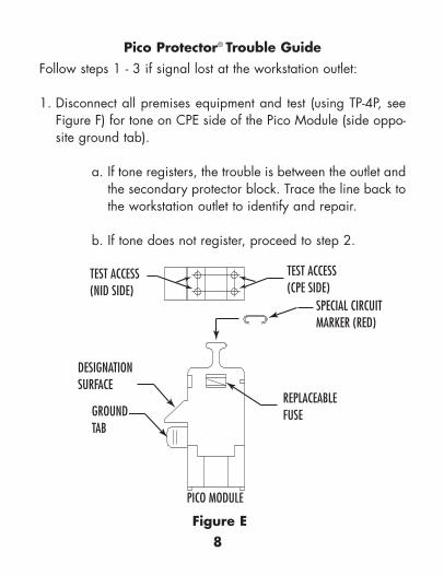
6. Circuit designations:
Write circuit designations on grounding-tab shroud of module.Slide optional red designation caps onto the handle to designatepriority circuits. See Figure E.
8
Pico Protector® Trouble GuideFollow steps 1 - 3 if signal lost at the workstation outlet:
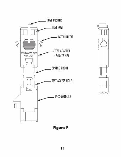
1. Disconnect all premises equipment and test (using TP-4P, seeFigure F) for tone on CPE side of the Pico Module (side oppo-site ground tab).
a. If tone registers, the trouble is between the outlet andthe secondary protector block. Trace the line back tothe workstation outlet to identify and repair.
b. If tone does not register, proceed to step 2.
Figure E
PICO MODULE
GROUNDTAB
DESIGNATIONSURFACE
TEST ACCESS(NID SIDE)
SPECIAL CIRCUITMARKER (RED)
TEST ACCESS(CPE SIDE)
REPLACEABLEFUSE

9
2. Test for tone on the NID side of the Pico Module (same side asground tab).
a. Tone registering on NID side but not on CPE sideindicates a blown fuse(s). Remove module andreplace spent fuse(s) using a 1/16” diameter probe(TP-4P). Fully seated fuses are recessed in housingapproximately 0.10 inch. Re-install the module andtest.
b. No tone on both the NID and CPE sides of theinstalled Pico Module indicates either a case of trou-ble on the incoming line or a transistor malfunction inthe module (provided that all premises equipment isdisconnected). See caution and proceed to step 3.
3. Remove the module and test the quick clips wired to the NID.
a. If tone registers, the transistor in the module hasfailed short to ground due to a catastrophic voltagesurge. Discard the old module and replace it with anew one of the same part number. Retest.
b. If no tone registers, the trouble is with the incomingline. Reinsert the module and test the circuit at thebuilding entrance point (NID) or primary protectionto isolate the trouble.
continued page 10
10
CAUTION:If no tone exists on both the CPE and NID sides of themodule and one or more of the fuses are blown, asustained voltage surge condition may exist that isbelow the breakdown voltage of the primary protec-tor. For this case, care must be taken by service per-sonnel to avoid electrical shock until the line ischecked and treated for the presence of an extempo-raneous voltage source.
11
Figure F
TEST POST
LATCH DEFEAT
TEST ADAPTER(P/N: TP-4P)
SPRING PROBE
FUSE PUSHER
TEST ACCESS HOLE
PICO MODULE

Accessory Information
© 2
006
Sie
mon
www.siemon.com
Rev.
B
06/
06
100
.153
3The AmericasWatertown, CT USAPhone (1) 860 945 4200
Europe/Middle East/AfricaSurrey, EnglandPhone (44 ) 0 1932 571771
Asia/PacificShanghai, P.R. ChinaPhone (86) 21 6390 6778
JapanTokyo, JapanPhone (03) 5437 1580
P/N Description Std. Pck.CP-675-C Red designation caps 100/bagTP-4P 4-point test probe 10/boxSF-035 Replacement fuses 20/bag
Modules:
P/N Clamping Level + 10% Std. Pck.PM-007 7V 100/ctn.*PM-027 27V 100/ctn.*PM-068 68V 100/ctn.*PM-140 140V 100/ctn.*PM-180 180V 100/ctn.*PM-230S 255V 100/ctn.*
*packed 25 per box