picmg 3.0 short form specification · 2018-11-14 · picmg 3.0 short form specification page 1 of...
TRANSCRIPT

PICMG 3.0Short Form Specification
January 2003
This short form specification is derived from the PICMG 3.0® Advanced Telecommunications Computing Architecture (ATCA) specification as approved on December 30, 2002 by the PICMG® Executive Membership. For guidelines on the design of the AdvancedTCA™ compliant boards and systems, refer to the full specification–do not
use this short form for any design decisions.
Copyright 2003, PCI Industrial Computers Manufacturers Group (PICMG)
PICMG disclaims all warranties and liability for the use of this document and the information contained herein and assumes no responsibility for any errors or omissions that may appear in this document, nor is PICMG responsible for any incidental or consequential damages resulting from
the use of any data in this document, nor does PICMG assume any responsibility to update or correct any information in this publication.
A dvanced TCA
TM
OverviewThis short form specification is a subset of the full AdvancedTCA™ base PICMG® 3.0 specification developed by PICMG®. This document is meant to provide background information for those interested in the progress and direction of the AdvancedTCA effort, but it is not a design document. Anyone wishing to design a board, backplane or system should obtain the full specifications from PICMG®. A PDF version of this short form specification can be downloaded from the AdvancedTCA section of the PICMG® Web Site at http://www.advancedtca.org. Note that the full document contains far more information and many sections not touched upon in this short form document.
Introduction and objectivesThe PICMG® (PCI Industrial Computer Manufacturers Group) 3.0 specification defines open architecture modular computing components that can be quickly integrated to deploy high performance services solutions. The PICMG® 3.0 family of specifications draws heavily on the PICMG® 2.0 experience by adopting the serial interconnect philosophy that has evolved there while making changes where they are indicated by that experience.
The PICMG® 3.0 specification is focused on the definition of an architecture that can:
• Enable reduced development time and costs
• Support reduced total cost of ownership
• Apply to edge, core, transport, and data center
• Apply to wireless, wireline, and optical network elements
• Support a rich mix of processors, digital signal processors (DSPs), network processors (NPs), storage, and input/output (I/O)
• Integrate with multiple network elements
• Provide multi-protocol support for interfaces up to 40 Gb/s
• Offer high levels of modularity and configurability
• Improve volumetric efficiency
• Improve power distribution and management
• Offer an advanced software infrastructure providing operating systems (OSs), application programming interface (API), and operation, administration, management, and provisioning (OAM&P)
• Offer world-class element cost and operational expense
• Provide high levels of service availability (99.999% and greater) through the integration of features for resiliency, redundancy, serviceability and manageability
• Support appropriate scalability of System performance and capacity
The objective of this document is to present base requirements, and, in some cases, suggest implementations for the PICMG® 3.0 Specification. Included is detailed information of the following elements that must be considered during development:
• Mechanicals
• System Management
• Power Distribution
• Power Connector Zone (for Dual -48 VDC power to each Slot)
• Rear I/O Access Zone
• Data Transport Connector Zone (for System management and switching fabric interconnect)
PICMG 3.0 Short Form SpecificationPage 1 of 33

• Shelf Thermal Dissipation
• Regulatory Guidelines
All signals are active high unless denoted by a trailing # symbol. Differential signals are denoted by a trailing + (positive) or – (negative) symbol.
Special terms and acronymsThe following terms and acronyms are used in specific ways throughout this specification:
Term Definition
Backplane A passive circuit board providing the Zone 1 and Zone 2 connectors for Front Board Slots. Link Ports of the Slots are connected via high speed signal pairs. Power distribution, management, and auxiliary signal connections are supported.
Component Side 1 When used in reference to an AdvancedTCA™ Board, the side on which the highest electronic components would be mounted. Identical with the Right side as defined below.
Component Side 2 When used in reference to an AdvancedTCA™ Board, the side normally reserved for making solder connections with through-hole components on Component Side 1 but on which low height electronic components may also be mounted. Identical with the Left side as defined below.
Data Transport Interface
The collection of point-to-point interfaces and bused signals intended to provide interconnect among the Payloads on Hub and Node Boards in Section 6 of the specification.
Dual-Dual Star Topology
An interconnect fabric topology in which four switch resources provide redundant connections to all end points within the network. Two pairs of Hub Boards provide redundant interconnects between Node Boards via two independent networks in parallel.
Dual Star Topology An interconnect fabric topology in which two switch resources provide redundant connections to all end points within the network. A pair of Hub Boards provide redundant interconnects between Node Boards.
Electronic Keying or E-Keying
Protocol used to describe the compatibility between the Base Interface, Fabric Interface, Update Channel Interface, and Synchronization Clocks connections of Front Boards.
Fabric Interface A Zone 2 interface that provides 15 connections per Board/Slot each comprised of up to 8 differential signal pairs (Channel) supporting connections with up to 15 other Slots/Boards. Backplanes may support the Fabric Interface in a variety of configurations including Full Mesh and Dual Star topologies. Boards that support the Fabric Interface may be configured as Fabric Node Boards, Fabric Hub Boards, or Mesh Enabled Boards. Board implementations of the Fabric Interface are defined by the PICMG® 3.x subsidiary specifications.
Field Replaceable Unit (or FRU)
Any entity that can be replaced by a user in the field. Not all FRUs are hot- swappable. At its most basic, the FRU does not have an IPM Controller on the assembly and, hence, is not directly controllable through the IPMI infrastructure. Basic product inventory data for the FRU may be maintained at a proxy IPM Controller elsewhere in the Shelf. Examples of this type of FRU might include: backpanel (the Shelf housing, for all practical purposes), power entry module, fan module, PMC, and RTMs.
Front Board or Board A Board that conforms to PICMG® 3.0 mechanicals (8U x 280 mm), including a PCB and a Panel. Further, a Board connects with the Zone 1 and Zone 2 Backplane connectors and, optionally, may connect with a Zone 3 Midplane Connector or directly to an RTM connector and is installed into the front portion of a Shelf.
Full Mesh Topology Full Mesh configurations may be supported within the Fabric Interface to provide one dedicated Channel of connectivity between each pair of Slots within a Shelf. Full Mesh configured Backplanes are capable of supporting Mesh Enabled Boards or Hub and Node Boards installed in a Dual Star arrangement. (aka Full Mesh Backplane)
PICMG 3.0 Short Form SpecificationPage 2 of 33

MechanicalThis section defines the essential mechanical features for PICMG® 3.0 compliant platforms. The Frame and Cabinet mounting standards, contained in ANSI/EIA 310-D Section 1, IEC 60297-1, and IEC 60297-2, govern the overall dimensions of the Shelf resulting in a “soft metric” equipment practice adaptable to telecommunications central office and data center installations throughout the world.
The basic elements of the platform are as follows (see Figure 1, “Form factor”):
• Front Boards containing the desired electronic functions and the connectors required to interface with these functions. The Front Board is 8U high, 30.48 mm wide, and approximately 280 mm deep. As mandatory features, the Front Board includes a Face Plate and two Handles. Optionally, the Front Board may include a cover on Component Side 2 and/or on Component Side 1. On the Front Board, three connector zones are defined: Zone 1 for power connection and Shelf management, Zone 2 for Data Transport Interface, and Zone 3 for user-defined IO (Input/Output) interconnect.
• RTMs providing user defined input and output connectivity to the companion Front Board from the rear.
• The Backplane providing connector interfaces for power distribution and input/output connectivity between Front Boards, as well as final mechanical alignment and support.
• The Subrack providing attachment points for the Backplane, as well as alignment, support, and mechanical engagement for the insertion and extraction of Front Boards and RTMs
Intelligent FRU A FRU containing an IPM Controller. Intelligent FRUs include the Node and Hub Boards, and they could also include other FRUs such as the fan tray, power supplies, alarm boards, etc.
Rear Board, Rear Transition Module, or RTM
An 8U x 70 mm x 6 HP assembly installed into the rear portion of a Shelf and mated with a Front Board through Zone 3 connectors to provide I/O connectivity.
Replicated Mesh Topology
Replicated Mesh configurations provide multiple Channels of Fabric Interface connectivity among the Slots within a Shelf. The number of Channels provided between any two Slots is dependent on the Slot count.
Shelf The Shelf consists of the Subrack, Backplane, Front Boards, cooling devices, RTMs, power supplies, etc. Also historically known as a chassis.
ShMC Shelf Management Controller. An IPMC that is also capable of supporting the functions required of the Shelf Manager.
Star A Backplane topology having one of more Hub Slots providing connectivity among the supported Node Slots
Subrack The Subrack provides the interface to PICMG® 3.0 Boards and consists of the Guide Rails, ESD discharge, alignment/keying, Handle interface, Face Plate mounting hardware, EMC gasketing, and Backplane interface. The Subrack is a subset of the Shelf.
Zone 1 The linear space along the height dimension of an AdvancedTCA™ Slot allocated for power, management, and other ancillary functions.
Zone 2 The linear space along the height dimension of an AdvancedTCA™ Slot allocated to the Data Transport Interface.
Zone 3 The linear space along the height dimension of an AdvancedTCA™ Slot reserved for user defined connections.
Term Definition
PICMG 3.0 Short Form SpecificationPage 3 of 33

Figure 1 Form factor
Note: Shelf may be 19”, 23”, or 600 mm ETSI.
Front Board assemblyThe Front Board PCB form factor shall be as defined in Figure 2, “Front Board PCB form factor.” See exceptions in Section 2.2.1 of the PICMG 3.0 specification.
Each Front Board shall provide a multi-segment discharge strip located on Component Side 1 along the bottom edge of the PCB. Covers may be used with Front Boards for stiffening the PCB, EMC and electrical protection, minimizing flame spread, and/or physical protection of components. The AdvancedTCATM Front Board to Front Board pitch shall be 30.48 mm (6 HP or 1.2 in). The PCB shall be positioned between two Pitch Lines so that the PCB's Component Side 1 surface shall be 6.61 mm from the left side Pitch Line. The maximum Component Side 1 height shall be 21.33 mm. The “no component zone” between the two Front Boards shall be 2.54 mm wide and shall provide for electrical Clearance to the next Front Board and/or the right-hand Subrack side wall for Front Boards.
The Front Board Face Plate shall be mounted into an 8U Subrack at a 6HP pitch (one Slot). The thickness of the Front Board is not defined in this specification. Face Plate metal thickness should be 1.0 mm to maintain a uniform look and feel among manufacturers. The Front Board Face Plate Handles shall rotate around the standoffs for the mandatory PCB mounting holes defined in Figure 2, “Front Board PCB form factor,” and shall be designed to have a Subrack interface.
Rea
r Acc
ess
Doo
r
280 mm 25 mm 5 mm5 mm
Front Board (8U x 280 mm)
(140 in2)
1.2” pitch
322.25 mm(12.697”)
Zone 2:• Keying/alignment• Synch. Clocks• Update Channels• Fabric Interface• Base Interface
Up to 4 standard PMCs
385 mm faceplate-to-faceplate
90mmOptical
Cabling/Air
Plenum
75mmMetallicCabling/
Air Plenum
Fron
t Acc
ess
Doo
r
90 mm 75 mm 25 mm25 mm
600 mm Cabinet
70 mm
Zone 3Zone 3
Rear panel IOInterconnect
Zone 2Z1
Rear Transition
Module(8U x
70 mmx 1.2”)(35 in2)
Zone 1:• Power• Management
PICMG 3.0 Short Form SpecificationPage 4 of 33
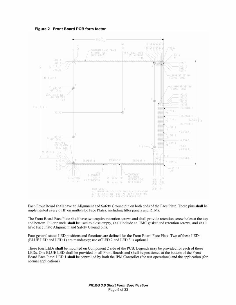
Figure 2 Front Board PCB form factor
Each Front Board shall have an Alignment and Safety Ground pin on both ends of the Face Plate. These pins shall be implemented every 6 HP on multi-Slot Face Plates, including filler panels and RTMs.
The Front Board Face Plate shall have two captive retention screws and shall provide retention screw holes at the top and bottom. Filler panels shall be used to close empty, shall include an EMC gasket and retention screws, and shall have Face Plate Alignment and Safety Ground pins.
Four general status LED positions and functions are defined for the Front Board Face Plate. Two of these LEDs (BLUE LED and LED 1) are mandatory; use of LED 2 and LED 3 is optional.
These four LEDs shall be mounted on Component 2 side of the PCB. Legends may be provided for each of these LEDs. One BLUE LED shall be provided on all Front Boards and shall be positioned at the bottom of the Front Board Face Plate. LED 1 shall be controlled by both the IPM Controller (for test operations) and the application (for normal applications).
PICMG 3.0 Short Form SpecificationPage 5 of 33

Front Board Face PlateThe Front Board Face Plate shall be as defined in Figure 3, “Front Board Face Plate and RTM Face Plate EMC gasket.” Front Board Face Plates provide for a PCB front I/O interface. An EMC gasket shall be located on the Component Side 2 edge of the Front Board Face Plate on both the Front Board and RTM.
The Front Board Face Plate shall be mounted into an 8U Subrack at a 6HP pitch (one Slot). The thickness of the Front Board is not defined in this specification. Face Plate metal thickness should be 1.0 mm to maintain a uniform look and feel among manufacturers. The internal surface of the Face Plate should not penetrate behind the Face Plate attachment plane.
Front I/O using devices requiring a return path to Shelf Ground shall implement this return path through the Face Plate ground pin.
The Face Plate shall provide for a Handle on both ends, Alignment and Safety Ground pin feature, and retention screws.
Face Plates may need to minimize insertion torsion to ensure proper seating and gasketing. This may be accomplished by adding stiffeners or additional attachment points between the Face Plate and the PBA.
Figure 3 Front Board Face Plate and RTM Face Plate EMC gasket
Front Board Face Plate Handles
The Handles shall rotate around the standoffs for the mandatory PCB mounting holes and shall be designed to have a Subrack interface. The Handle should allow for maximum vertical Face Plate I/O space. The maximum length of the Handle along the Face Plate shall be 50 mm from the center of the mounting hole.
PICMG 3.0 Short Form SpecificationPage 6 of 33

A positive mechanical stop or other means shall be provided to locate Handles at their proper angular position prior to Front Board insertion.
An implementation for the Handle Switch and latch mechanism is shown in Figure 4, “Example of Handle Switch and latch mechanism.” Note that this example implementation mounts the switch on the return flange of the Face Plate, so a single packaging supplier can supply it along with the Front Board Face Plate, Handle, and retention mechanism.
Figure 4 Example of Handle Switch and latch mechanism
Provision for using optional CMC/PMC Mezzanine Cards
Optionally, one or more “Common Mezzanine Cards” (CMCs) and “PCI on a CMC” (PMCs) may be assembled to Boards.
A maximum of four (4) CMCs or PMCs of 75 mm width are possible along the height dimension of a Front Board. With the ejectors illustrated above, approximately 304 mm of vertical space between space required for ejector handle mounting. Note that the overall length of the handles does not effect the front panel space available for mezzanines.
This provides approximately 2 mm clearance on either end of four CMC/PMC cards, each with a 75 mm wide envelope.
RTM assemblyRTMs are optional. RTMs simplify servicing of Front Boards by putting I/O cable assemblies on the RTM. I/O signals from the Front Board are routed to Zone 3 where a user-defined connector mates with the RTM and takes the signals outside the rear of the Shelf. This allows Front Boards to be quickly and reliably serviced without the issues associated with disconnecting and reconnecting multiple cable assemblies.
PICMG 3.0 Short Form SpecificationPage 7 of 33

If RTMs are used, they may connect to the Front Board via Zone 3 connections, but they shall not make any connection to the Zone1/Zone 2 Backplane (except the rA1 alignment/keying feature).
This specification defines the RTM envelope and electromechanical interfaces. The specific implementation of an RTM may be a PCB, wiring harness, or other construction and is left to the user.
If the RTM consists of a PBA, it shall be “in-line” with the Front Board. The EMC gaskets of the RTMs shall be located on Component Side 2 of the Face Plate.
Zone 1, 2, and 3 connectorsThe Zone 1 connector shall be the only interface between AdvancedTCATM Backplanes and Front Boards for dual redundant -48 VDC power, metallic test, ringing generator, Shelf management system connections, and Hardware Addressing.
Zone 2 defines the use of five Backplane connectors, P20 through P24, to support the Data Transport Interface. It provides for up to five ZD connectors per Front Board to cover the Base Interface, Fabric Interface, Update Channel Interface, and Synchronization Clock Interface.
Zone 3 includes space for keying and 95.1 mm PCB edge space for connectors. It provides a flexible method for user defined I/O signals to be routed to either an RTM, a Zone 3 midplane extension, or a bulkhead-mounted connector. The connector type in Zone 3 is not defined, rather it is left to the user to choose the interconnect technology that best meets the requirements.
The connector type in Zone 3 is not defined; rather, it is left to the user to choose the interconnect technology that best meets the requirements. A2/K2 alignment and keying shall be used to prevent incompatibilities.
Front Board and RTM alignment/keyingThe Front Board is aligned by a four-stage alignment system: 1) Gross alignment in the Subrack is achieved as the PCB edge is positioned within the Guide Rails; 2) The Alignment and Safety Ground pins on the Backplane and RTM align with the receptacles on the Front Board or RTM; 3) The Alignment and Safety Ground pins on the Front Board Face Plate align with the receptacles in the horizontal members; and 4) The alignment features of the Zone 1 and Zone 2 connectors themselves (note: Zone 1 mates first).
Keying is used to prevent a mismatch between Front Boards and Backplanes or between Front Boards and RTMs. Physical keying prevents the installer from damaging connectors by attempting to mate a Front Board to a midplane or RTM that have incompatible connector types, offset connector locations, or incompatible voltage levels that cannot be handled by Electronic Keying.
For Zone 1 and Zone 2 connector alignment, Backplane alignment features shall be implemented to ensure Front Board and Backplane connectors are aligned properly during mating. The Backplane shall implement the A1 alignment/keying feature at every Slot position as shown in Figure 5, “Backplane alignment/keying feature (A1).”
The Front Board shall implement the K1 keying/alignment feature as shown in Figure 6, “Front Board and alignment/keying features (K1, K2).”
PICMG 3.0 Short Form SpecificationPage 8 of 33

Figure 5 Backplane alignment/keying feature (A1)
Figure 6 Front Board and alignment/keying features (K1, K2)
PICMG 3.0 Short Form SpecificationPage 9 of 33

BackplanesPICMG® 3.0 Backplanes shall have thickness from 3 to 8 mm. The number of Front Board Slots accommodated by the Backplane shall be between 2 and 16. The Backplane has mounting holes to attach to the subrack, mounting holes for a Backplane support bar, and mounting holes for an alignment/keying mechanism that is located above the Zone 2 connectors.
The Backplane distributes power, metallic test bus, ring generator bus, and low-level Shelf Management signals through the Zone 1 connectors. The Base Interface, Fabric Interface, Update Channel Interface, and Synchronization Clock Interface signals are distributed through the Zone 2 connectors.
SubrackThe Subrack provides the mechanical interface to PICMG® 3.0 Front Boards and consists of: Guide Rails, ESD discharge clips, alignment/keying, Handle interface, Face Plate mounting hardware, EMC gasketing, and Backplane interface. The Subrack construction materials and design details are not defined; only the Front Board to Subrack interface dimensions are defined.
The Subrack shall support PICMG® 3.0 form factor Front Boards. A Subrack shall provide for an 8U front height and the Dc depth dimension (295.6 mm ± 0.5 mm). The Backplane support bar shall provide for Zone 1/Zone 2 Backplane to Subrack attachment features.
The Subrack front and (optional) rear shall provide for the Face Plate Alignment and Safety Ground pin/25 A ground receptacle and the retention screw M3 threaded holes. The EMC Subrack gasket shall be mounted on the right side of the front Subrack opening (when viewed from the front).
The Front Board and RTM Guide Rails shall have the PCB guidance feature in the 6.61 mm offset position and shall be present at every 6 HP in the Subrack. The Subracks shall hold the Front Board and optional RTMs under the specified shock, vibration, and earthquake test requirements.
The Subrack shall provide Alignment and Safety Ground pin receptacles to mate with pins at both ends of the Front Board Face Plate and Face Plates for the optional RTM.
The Subrack shall provide M3 threaded retention screw receptacles at the Front Board attachment surface and RTM attachment surface.
The Subrack, as part of the structure of the Shelf, shall support the weight of the Front Boards and optional RTMs.
Subrack integrity tests provide Subrack/Shelf manufacturers with design/test requirements for establishing minimum performance acceptance levels and providing guidance when the end user system configuration is unknown.
Physical Slot numbering shall begin from left to right for Front Boards as viewed from the front in the standard orientation and from bottom to top in the horizontal orientation. Numbering shall begin with numeral 1 and shall increase by increments of one.
ShelfThe Front Board form factor has been designed for use in a 12U vertical system, but alternate Shelf configurations such as low-profile “pizza boxes” and other system sizes are allowed. Since Front Boards require filtered air, Shelves shall provide filtering unless filtering is provided elsewhere. Each Shelf shall provide a wrist strap terminal on the front of the Shelf. Wrist strap terminals shall be unpainted terminals connected to Shelf Ground and shall be marked to indicate ESD function. A banana plug/jack assembly shall be used for the ESD wrist strap connections. Shelf-level alarm reporting resources may be provided on the Shelf.
PICMG 3.0 Short Form SpecificationPage 10 of 33

Cable management must be determined at the Frame, Shelf, and Front Board/RTM level. Within each of these three areas, there are three types of cable management to be considered: power cable management, I/O copper cable management, and I/O optical fiber cable management.
Power entryPower entry into a PICMG® 3.0 Shelf is subject to various end customer requirements. The distribution of the main “A” and “B” office Feeds vary. The Feeds may be connected to the Shelf using single points with adequate rating.
Power entry terminals or connectors shall meet the accessibility and spacing requirements in Sub-clause 2 of IEC 60950. Power entry may be by connector or by power stud. If a connector is used, it shall be a keyed or polarized connector.
Shelf mounting hole pattern and locationShelf mounting patterns vary depending upon the end-user environment. Two major standards to design for are:
• Inch-based mounting hole pattern per EIA-310 and IEC 60297-1
• Metric-based mounting hole pattern per IEC 60917-2
Shelf mounting location varies depending upon the end-use environment. There are three basic options:
• Front flange mount
• Midmount
• Front mount and rear mount support
Shelf managementAdvancedTCA™ provides for extensive management capabilities, which may be used by the overall System Manager. Multiple levels of management services are provided or facilitated:
• Low-level hardware management services
• High speed management services based on the TCP/IP protocol suite
• In-band application management
The Shelf management content of this specification focuses on the low level hardware management services. An architecture for high-speed management services is outlined. In-band application management is outside the scope of this specification.
The Shelf management system does the following:
• Monitors, controls, and assures proper operation of AdvancedTCA™ Boards and other Shelf components
• Watches over the basic health of the system, reports anomalies, and takes corrective action when needed
• Retrieves inventory information and sensor readings as well as receive event reports and failure notifications from Boards and other Intelligent FRUs
• Performs basic recovery operations such as power cycle or reset of managed entities
• Provides low-level hardware management services to manage the power, cooling, and interconnect resources of a Shelf
Advanced TCA™ allows systems with either 1) all components operated by a single owner or 2) components operated by multiple owners (Multi-tenancy).
The Shelf management system is comprised of several major components:
PICMG 3.0 Short Form SpecificationPage 11 of 33

• Distributed management controllers that manage and monitor the operation and health of each FRU in the system.
• An Intelligent Platform Management Interface (IPMI) infrastructure that provides communications, management, and control among the distributed controllers and to an overall System Manager.
• A higher-level, high-speed service for Boards that need TCP/IP-based management services such as remote booting, SNMP management, remote disk services, and other IP-based services.
Shelf management architectureFigure 7, “Management aspects of an example of AdvancedTCA™ Shelf,” shows the logical elements of an example AdvancedTCA™ Shelf, with an emphasis on management-related aspects.
Figure 7 Management aspects of an example of AdvancedTCA™ Shelf
System MangerThe System Manager is the highest-level management entity in this specification. It is responsible for managing one or more Shelves and possibly one or more Systems. It is a logical entity for the purpose of explanation and is outside the scope of this specification. Figure 7, “Management aspects of an example of AdvancedTCA™ Shelf,” shows a Shelf-external System Manager. In some systems (e.g., single-Shelf systems), the System Manager may be integrated into the Shelf.
AdvancedTCA™ Shelves have one or more redundant transports capable of supporting the internet protocol and linking a Shelf-external System Manager to the Shelf Manager (which is preferably redundant) and the AdvancedTCA™ Boards in a Shelf. These links may be Ethernet and/or another IP-capable transport. Two key uses of these links are:
• Communication between a System Manager and a Shelf Manager.
• Support of the IP-based management services (such as remote booting) for those Boards that need them.
ShMC
FanTray
PowerEntry
Module
IPMC
Shelf-External System Manager
ShelfManager(Active)
ShelfManager(Backup)
ATCABoard
ATCABoard
ATCABoard
ATCABoard
ATCABoard
ATCABoard
ATCABoard
ATCABoard
2x Redundant, Bussed or Radial, IPMB-0
2x Redundant Radial Internet-Protocol-Capable Transport
ImplementationDependentConnection
Key
IPM Controller (IPMC)
Shelf Management Controller (ShMC)
AdvancedTCA Board
Shelf Manager w/ Dedicated ShMC
Other Field Replaceable Unit (FRU)
ShMC
IPMC IPMC IPMC IPMC IPMC IPMC IPMC
PowerEntry
Module
IPMC
PICMG 3.0 Short Form SpecificationPage 12 of 33

The principal management-oriented link within a Shelf is a two-way redundant implementation of the Intelligent Platform Management Bus (IPMB), which is based on the inter-integrated circuit (I2C) bus and is part of the IPMI architecture. In AdvancedTCA™ Shelves, the main IPMB is called IPMB-0 and is implemented on either a bused or radial basis. Each entity attached to IPMB-0 does so via an IPM Controller, the distributed management controller of the IPMI architecture. Shelf Managers attach to IPMB-0 via a variant IPM Controller called the Shelf Management Controller (ShMC).
The Shelf Manager does the following:
• Watches over managed devices, reporting anomalous conditions to the System Manager and taking whatever corrective actions it can to prevent system failure
• Handles hot-swap events from removable devices, indicating their entry into the Shelf and detecting their shutdown or removal
• Plays the role in AdvancedTCA™ of IPMI's BaseBoard Management Controller (BMC). (In this section, the terms Shelf Manager and ShMC will be used instead of BMC.)
• Negotiates power budgets with Boards and other FRUs so that the Shelf operates within those capacities.
• Initiates changes in fan levels when event messages show that temperatures are outside of prescribed bounds.
AdvancedTCA™ Boards are Field Replaceable Units (FRUs). Figure 8, “Management aspects of an alternate example AdvancedTCA™ Shelf,” also shows three other FRUs: a fan tray and two separate Power Entry Modules.
Figure 8 Management aspects of an alternate example AdvancedTCA™ Shelf
The Power Entry Modules in Figure 8, “Management aspects of an alternate example AdvancedTCA™ Shelf,” are one example of an IPM Controller representing other FRUs, but there are many other possibilities. An IPM Controller may implement additional FRUs that do not show up in the Address Table (e.g., plug in modules also known as mezzanines). Therefore, the “Get PICMG Properties” command provides a mechanism for querying for the maximum FRU Device ID supported by the IPM Controller. Notice that this command also contains a version
FanTray
PowerEntry
Module
ShMC
Shelf-External System Manager
ATCABoard
ATCABoard
ATCABoard
ATCABoard
ATCABoard
ATCABoard
ATCABoard
ATCABoard
2x Redundant, Bussed or Radial, IPMB-0
2x Redundant Radial Internet-Protocol-Capable Transport
ImplementationDependentConnection
ShMC IPMC IPMC IPMC IPMC IPMC IPMC
PowerEntry
Module
IPMC
Key
IPM Controller (IPMC)
Shelf Management Controller (ShMC)
AdvancedTCA Board
Shelf Manager
Other Field Replaceable Unit (FRU)
ShelfManager(Active)
ShelfManager(Backup)
PICMG 3.0 Short Form SpecificationPage 13 of 33

number for all the commands in this specification.Another example: an AdvancedTCA™ Board may have mezzanine modules installed on it. The IPM Controller on that Board would represent those FRUs to IPMB-0 and the rest of the IPMI infrastructure.
AdvancedTCA™ defines two types of FRUs that are visible to and controlled through the IPMI infrastructure:
• Intelligent FRUs physically include an IPM Controller.
• Managed FRUs are either Intelligent FRUs or represented by an Intelligent FRU and visible to the IPMI infrastructure.
Each FRU that directly attaches to IPMB-0 must be an Intelligent FRU.
This specification intentionally enables a wide range of implementation options for Shelf Managers (Figure 7, “Management aspects of an example of AdvancedTCA™ Shelf,” and Figure 8, “Management aspects of an alternate example AdvancedTCA™ Shelf,” show just two of them). The Shelf Manager could even partially execute on Shelf-external hardware.
Furthermore, this specification strongly recommends that redundant Shelf Manager instances be provided but does not standardize the mechanisms by which an active Shelf Manager instance fails over to its backup(s). The selection of the backup, coherency of redundant information, and the fail-over process are all outside the scope of this specification.
Another important function of the Shelf Manager is to ensure that Boards only enable interfaces between AdvancedTCA™ Backplane interconnects that are compatible, so that incompatible devices do not cause harm to each other. This function, called Electronic Keying, assures compatibility of all devices within the Shelf. Each Board's IPM Controller contains FRU information that indicates the capabilities of each Port implemented in the Base, Fabric and Update Channel Interfaces on the Board. Additionally, the Shelf Manager has access to FRU information describing the connectivity of the Shelf Backplane. By coordinating the information from these sources, the Shelf Manager decides which Ports on each Board should be enabled or disabled and conveys that information to each Board via IPMB to the Board's IPM Controller. The Board's IPM Controller then ensures that only compatible interfaces are enabled.
Access to each IPM Controller's resources is controlled by Sensor Data Records (SDRs) accessible from the device through Device SDR commands. This includes, for example, all sensors and FRU information. Device SDRs are queried by the Shelf or System Manager over the IPMB-0 interface. Notably, any sensor that is not described by an SDR accessible from the IPMB-0 interface is not directly known to the Shelf or System Manager.
Figure 9, “Example Board interfaces,” shows the high-level interfaces on an example Board. All the interfaces that cross the Board boundary in the example are AdvancedTCA™-specified Board and Slot interfaces; here they are:
• Dual redundant -48 VDC power from the Backplane. The DC/DC converter provides management power for the IPM Controller, and, when enabled, power for the rest of the Board.
• Dual redundant IPMB-0 that provides the primary in-Shelf management link to the IPM Controller.
• Fabric, Base, and Update Channel Interfaces that constitute the Backplane interconnects implemented in a particular Board and Slot. The IPM Controller, through the Electronic Keying process, enables the appropriate subset of the Ports on those interconnects.
The main part of the example Board is its “Payload,” which implements the main function of the Board (not addressed in this generic example, of course). In addition to the Payload, there is a DC/DC conversion block plus the IPM Controller and its non-volatile storage.
PICMG 3.0 Short Form SpecificationPage 14 of 33

Figure 9 Example Board interfaces
Finally, there are several on-Board interfaces to the IPM Controller. The Payload Interface enables communication between an IPM Controller and its Payload. For maximum implementation flexibility, AdvancedTCA™ leaves the details of the Payload Interface entirely to the Board implementer. Optionally, a Board can connect its IPM Controller directly to the Base Interface (as shown in the example with a dashed line) or to one of the other Backplane interconnects. The IPM Controller uses non-volatile storage for various purposes, including as a repository for the FRU information that describes the Fabric, Base, and Channel Update Interfaces implemented by that Board for use in Electronic Keying.
Internet Protocol based servicesAdvancedTCA™ Shelves support higher-level services, based on the TCP/IP protocol suite, for Boards that need them. These services may include but are not limited to the following:
• Simple Network Management Protocol (SNMP)
• Remote Boot
• Disk Services (such as the Network File Services, NFS, and iSCSI)
• Web-Based Enterprise Management Protocol (WBEM)
• Remote Management Control Protocol (RMCP)
These services are expected to be primarily used by the Payload processor on a Board to facilitate its lower-level operations. They are not provided for application-level management. Like the IPMB-0 interconnects, this facility is also provided over a redundant communications media in order to assure operation in case one of the connection paths fails.
Board Payload
Non-VolatileStorage
DC/DCDC/DCConConverter
IPMController
Payload Power
Enable‡
ManagementPower
PayloadPower
PayloadInterface
2x -48VDC† IPMB-0†
FabricInterface†
BaseInterface†
UpdateChannelInterface†
BackplaneInterconnect
Enable‡
† ATCA-specified Board/Slot interfaces
‡ On-board controlsignals
OptionalLink to IPMController
PICMG 3.0 Short Form SpecificationPage 15 of 33

The Internet Protocol Based Services operate over IP capable interconnects. This specification allows for the IP communications to be carried over non-Ethernet physical layers that provide a suitable standard IP encapsulation service and can guarantee bandwidth as required by the management system.
Services provided over this Channel are left to the implementors to determine based on their specific needs. Boards not requiring TCP/IP management services are not required to implement these interfaces. However, the Shelf Backplane is required to implement these IP-capable interconnects to facilitate operation of any Boards that require them.
Multi-tenant architecturesIn developing the AdvancedTCA™ specification a new architecture termed Multi-tenancy has been introduced. While it is not the intention of this specification to define one or more ways to implement Multi-tenant architectures (see below), it is important to consider such architectures to ensure this specification does not preclude their implementation.
IPM ControllerAll AdvancedTCA™ systems support an “intelligent” hardware management system, based on the Intelligent Platform Management Interface Specification. The hardware management system provides the ability to manage the power, cooling, and interconnect needs of intelligent devices; to monitor events; and to log events to a central repository. Intelligent AdvancedTCA™ FRUs contain an IPM Controller.
AddressingEach IPM Controller in the Shelf has multiple addressing schemes. The four types of addresses that are important to an IPM Controller are Hardware Address, Intelligent Platform Management Bus Address, Physical Address, and Shelf address.
System Event Logs (SELs)The System Event Log is the collection of IPMI events that are generated by all IPM Controllers throughout the Shelf. In a traditional IPMI system, the BMC is the sole maintainer of the System Event Log. In AdvancedTCA™ however, there are practical reasons not only to have a single centralized SEL but also allow event entries to be duplicated among the IPM Controllers. By duplicating such information and storing it in non-volatile memory, the event logs for a FRU can stay with that FRU if the FRU is moved or removed. This allows for better tracking of error conditions and facilitates troubleshooting and repair. However, some vendors may choose not to attach event logs to particular FRUs in order to save costs.
IFRU InformationAn early and important feature of system management is its inventory management capability. Sections 1.6.11 through 1.6.14 of the IPMI specification provide an overview of FRU Information principles and implementations. While the IPMI specification highly recommends that each IPM Controller implement the “FRU Inventory Device” commands, this document makes that a requirement of each IPM Controller.
Intelligent Platform Management BusAn AdvancedTCA™ Shelf uses IPMB (Intelligent Platform Management Bus) for management communications among all Intelligent FRUs. The reliability of the IPMB is improved by the addition of a second IPMB, with the two IPMBs referenced as IPMB-A and IPMB-B. The aggregation of the two IPMBs is IPMB-0. The IPM Controllers aggregate the information received on both IPMBs. An IPM Controller that has a message ready for transmit will use the IPMBs in a round robin fashion. An IPM Controller will try to alternate the transmission of messages between
PICMG 3.0 Short Form SpecificationPage 16 of 33

IPMB-A and IPMB-B. If an IPM Controller is unable to transmit on the desired IPMB then it will try to send the message on the alternate IPMB. By using this approach, an IPMB can become unavailable and then available without the IPM Controller needing to take specific action.
Shelf power and coolingThe Shelf Manager controls power and cooling of the Shelf. Managing power and cooling involves three stages of Shelf status: Discovery, Normal Operation and Abnormal Operation.
In the Discovery stage, the Shelf Manager collects data from the Shelf and from Boards and other FRUs regarding their power capabilities and requirements. During Normal Operation the Shelf Manager awaits event messages from Boards and/or FRUs to make any adjustments to Shelf cooling or power distribution from the current operation conditions. The Abnormal Operation Stage occurs when a Board or FRU generates an Event Message requesting Shelf services from the Shelf Manager.
Power distributionThis section describes power distribution at the Shelf and Board level for PICMG® 3.0 products. Any information relating to Frame or Cabinet level power distribution is for information only and is not mandatory.
Dual -48 VDC power distributionDual, redundant -48 VDC Feeds are provided to each Frame from the one or two power plants within a facility. In some facilities, a signal-conditioning panel, usually mounted at the top of the Frame, provides filtering to minimize radiated and conducted noise, Feed cable inductor compensation, overcurrent protection, and voltage ripple. The two primary Feeds are typically split into a number of branches but remain electrically isolated. These branches are then also fused and filtered to prevent downstream shorts and malfunctions from propagating beyond a single Shelf or sub-Shelf. Shelves requiring modest power may be fed by a single pair of Feeds or by multiple pairs of Feeds to keep the current per Feed to a modest level. Figure 10, “Shelf level power distribution example (2 Feeds),” illustrates this concept. (For simplicity, fusing is not shown in the diagram.)
Figure 10 Shelf level power distribution example (2 Feeds)
16-Slot Backplane
Slot
1Sl
ot 2
-48VDCFeed A
Zone 1 Power Connector
-48VDCFeed B
Slot
16
OptionalPower
Filtering& Circuit
Protection
16-Slot Backplane
Slot
1Sl
ot 2
-48VDCFeed A
Zone 1 Power Connector
-48VDCFeed B
Slot
16
OptionalPower
Filtering& Circuit
Protection
PICMG 3.0 Short Form SpecificationPage 17 of 33

Multiple branches from each Battery Plant may also be used to minimize fault domains and increase reliability. In cases where multiple branches are used from each Battery Plant, the Backplane is segmented to maintain isolation between all branches, as shown in Figure 11, “Shelf level power distribution example (8 Feeds).”
Figure 11 Shelf level power distribution example (8 Feeds)
Power architecturePICMG® 3.0 Shelves shall:
• Provide (and Boards shall receive) dual DC Feeds (referred to in this document as “Feed A” and “Feed B”)
• Distribute filtered power Feeds to each Front Board through the Zone 1 connector
Supported voltage levelsFigure 12 ETS 300 132-2 static voltage levels
-48 VDC systems -60 VDC systems
Nominal operating voltage -48 VDC -60 VDC
Maximum operating voltage -57 VDC -72 VDC
Minimum operating voltage -40.5 VDC -50 VDC
Degraded operating voltage -40.5 VDC to -44 VDC Not specified
Non-operating voltages with no equipment damage
0 VDC to -40.5 VDC, -57 VDC to -60 VDC
0 VDC to -50 VDC, -72 VDC to -75 VDC
16-Slot Backplane
Slot
1Sl
ot 2
-48VDCFeed A1
Zone 1 Power Connector
OptionalPower
Filtering& Circuit
Protection
-48VDCFeed A2
-48VDCFeed A4
OptionalPower
Filtering& Circuit
Protection
-48VDCFeed A3
-48VDCFeed B1
-48VDCFeed B2
-48VDCFeed B4
-48VDCFeed B3
OptionalPower
Filtering& Circuit
Protection
OptionalPower
Filtering& Circuit
Protection
Slot
16
16-Slot Backplane
Slot
1Sl
ot 2
-48VDCFeed A1
Zone 1 Power Connector
OptionalPower
Filtering& Circuit
Protection
-48VDCFeed A2
-48VDCFeed A4
OptionalPower
Filtering& Circuit
Protection
-48VDCFeed A3
-48VDCFeed B1
-48VDCFeed B2
-48VDCFeed B4
-48VDCFeed B3
-48VDCFeed B1
-48VDCFeed B2
-48VDCFeed B4
-48VDCFeed B3
OptionalPower
Filtering& Circuit
Protection
OptionalPower
Filtering& Circuit
Protection
Slot
16
PICMG 3.0 Short Form SpecificationPage 18 of 33

Single or multiple Feeds to the Shelf and BackplanePICMG® 3.0 systems are capable of dissipating as much as 200 W per single-Slot Board in addition to the power consumption requirements of the fans and other Shelf elements. In a 16-Slot Shelf, over 3200 W of office battery power must be provided through Battery Plant wiring. Either monolithic load wiring (one set of power inputs for the Shelf) or distributed load wiring (multiple sets of power inputs, each providing power to a subset of Shelf Slots) may be utilized.
Fusing and fault protectionIn this section, the term “fuse” or “fusing” will be used to describe any circuit protection devices that are intended to interrupt DC power in the event of an over current situation. These devices might include conventional fuses, circuit breakers, in-line semiconductor devices, such as IGBTs (Insulated Gate Bipolar Transistors) or FETs (Field Effect Transistors), or other protection devices.
Fusing is a complex issue, and this specification describes the minimum required for PICMG® 3.0 compliance. Individual designs can incorporate more sophisticated fusing and circuit protection, although care should be taken to ensure that the overall system management architecture can determine where faults, due to fuse opening or other circuit protection devices, have occurred.
Fusing and power monitoring at the Frame level are outside the scope of this document.
Shelf-level fusing can be used to protect the Shelf and Backplane in the event of an abnormal fault such as mis-wiring of Shelf power, conductive particulate contamination, or other events. It is not required to perform this function since some installations rely on Frame-level PDUs.
Board level fusing shall be provided on each -48 VDC Feed and its corresponding return as it enters the Board. Since there are dual Feeds, there shall be at least four fusing devices, and they shall be located between the individual Feeds as they enter the Board and any diode OR’ing or power conversion that might take place to combine the two Feeds into a single supply or return on the Board.
FilteringPICMG® 3.0 specifies a standard set of Board and Shelf level requirements to allow inter-operability while maintaining appropriate agency conducted and radiated emissions requirements. Since -48 VDC is distributed to all active components of the Shelf, the primary noise source in the Shelf is typically the DC-DC converters that convert -48 VDC to the various regulated voltage rails required by the Board or FRU.
Board and Shelf conducted emissions
The main filtering function is performed in the Board. The Board shall ensure that the conducted emissions remain below the levels of CISPR 22 Class B.
The specification mandates that the main emissions filtering function is performed in the Board. The Shelf will aggregate the conducted emissions from up to 16 Boards. This requires a minimum attenuation of 11.5 dB. To provide a good margin, the Shelf shall provide an attenuation of 18 dB between 150 kHz and 30 MHz. The Shelf should provide a minimum of 18 dB of attenuation in the frequency range of 30 MHz to 1.0 GHz.
Radiated emissions
Radiated emissions are difficult to specify and test without a full system. Boards are the primary source of radiation, and it is the responsibility of the Board designer to reduce emissions. The enclosure designer is responsible for ensuring a reasonably closed EMC shield, but it is up to the system designer/integrator to test the system against the required standards.
PICMG 3.0 Short Form SpecificationPage 19 of 33
Board power sequencingPower sequencing in the Board takes place at two levels: the hardware level and the hardware management level. The hardware power sequencing, which follows, ensures a safe insertion and withdrawal of a Board. The hardware management system then takes over to ensure that the Board is powered up in a manageable configuration.
Power and ground sequencing
During a Board insertion, the ESD segment #1 and the Guide Rail provide the first electric contact between the Board and the Shelf. This contact provides a discharge path to the Shelf Ground. The second ESD segment discharges Logic Ground.
Power sequencing is provided by pins of different lengths in the power connector and the Subrack
The first pins to mate in the power connector are the logic and Frame/Shelf Grounds and the EARLY_A; EARLY_B; VRTN_A; and VRTN_B pins. The EARLY_A and EARLY_B pins allow for the pre-charge of the power converter input capacitance. At a 0.5 meters per second insertion rate, this provides a 3 millisecond time period between the early power contact and the ENABLE_A contact. Operational power for a Board shall be drawn through -48V_A and -48V_B. Board designers may use the EARLY_A and EARLY_B pins for pre-charge or may leave the pins disconnected.
The last pins to engage in the power sequence are the enable pins ENABLE_A and ENABLE_B. Backplanes shall connect EARLY_A to -48V_A; EARLY_B to -48V_B; ENABLE_A to VRTN_A; and ENABLE_B to VRTN_B.
Management power
Boards in the Subrack shall not consume more than 10 W total power (including consumption at the on-board power converters) from all power sources until they have negotiated power-up rights with the Shelf Manager. This includes powering the IPM Controller and idle power consumed in the power converters.
Payload power
FRUs must not turn on Payload power until they have negotiated with the Shelf Manager to do so. Each FRU shall have an IPM Controller responsible for controlling FRU power above the management/idle power.
Grounding strategy
Shelf GroundAll front Panels (including those for Front Boards, RTMs, and Shelf elements such as fan trays) shall be connected to Shelf Ground. Each FRU should be connected to Shelf Ground through both a reliable Face Plate connection and through a Backplane connector.
Each Shelf shall provide at least one dual-pole grounding lug for Shelf Ground.
Shelf Ground and –48 VDC returnBoth Mesh and SPR (single-point return) grounding strategies are in common use. In SPR environments, the Shelf (safety) ground wiring is kept separate from the –48VRTN lines all the way to the Battery Plant, where they are eventually tied together. In a meshed ground environment, the safety grounds and return lines are tied together at equalization plates throughout the facility. In meshed grounding environments, the same cabling is often used for both Shelf Ground and –48VRTN; this is commonly called a “2-wire” system (-48VDC, -48VRTN/SHELFGND). In SPR environments, Shelf Ground must be maintained separately; this is commonly called a “3-wire” system (-48VDC, -48VRTN, SHELFGND). Three-wire systems are the most restrictive from a design perspective.
PICMG 3.0 Short Form SpecificationPage 20 of 33
PICMG® 3.0 Shelves shall isolate the -48 VDC return lines from Shelf Ground. However, Shelves shall provide a mechanism at the Shelf level to provide the installer the option to tie the Shelf Ground and -48 VDC return lines A and B together.
Shelf Ground and Logic GroundRequirements regarding Logic Ground and Shelf Ground isolation vary in different telecom applications.
A Front Board and RTM shall have a DC resistance of greater than 9 MOhms between Logic and Shelf Grounds as measured with a 100 V test voltage.
A Shelf shall provide a mechanism to interconnect Logic Ground and Shelf Ground. Each Front Board, RTM, or FRU should provide a mechanism for an installer-configurable, low-impedance connection between Logic Ground and Shelf Ground in the vicinity of the Face Plate. The impedance value is application specific.
Board-level power conversionEach -48 VDC Feed remains isolated and is fed individually to each Board Slot through the Backplane. There are two basic methods for combining the dual redundant Feeds.
One method combines the two Feeds through diode OR'ing and delivers the combined single Feed to on-FRU DC/DC converter(s). If either Feed fails, all power shall be delivered by the surviving Feed.
The second method is to direct each of the two Feeds to its own DC/DC converter. The outputs of the converters are then combined to provide power to the on-FRU circuits.
ThermalThis section provides thermal information to the designer, manufacturer, integrator, or user of a PICMG® 3.0 system to facilitate inter-operability among the many components that must work together for a successful thermal solution. While this specification provides guidance, the system integrator shall have the ultimate responsibility to ensure all components meet the thermal requirements of the system.
An example airflow path for a PICMG® 3.0 system cooled by forced air convection in Figure 13, “Example of Shelf airflow,” is for demonstration purposes only. Air enters the Shelf at the lower front into the bottom air plenum and turns 90° upward. Airflow across the bottom edge of the Front Board and RTM is evenly distributed. As the air passes across the hot components on the Front Board and RTM, heat is carried away by forced convection. The air exits the Subrack at the top, is drawn into the upper plenum, turns 90°, and is exhausted out the rear of the Shelf by fans. Other airflow paths and cooling methods are allowed. This example does not apply to a system cooled by natural or free convection.
Air coolingThe majority of equipment installed in central office and data centers today is air cooled due to simplicity, relatively low cost, ease of implementation, and reliability. This trend is likely to continue into the future for the same reasons. The thermal guidelines in this specification apply to air cooling. Other cooling methods are permissible but are not covered in this specification. Boards, Shelves, and Frames may be either cooled by natural convection, without the assistance of fans or blowers, or cooled by forced convection with the assistance of fans or blowers. The choice is left to the end-user requirements. Guidelines are provided for volumetric airflow requirements per Front Board, RTM, Shelf, and Frame using a 10 ºC air temperature rise rule of thumb.
PICMG 3.0 Short Form SpecificationPage 21 of 33

Figure 13 Example of Shelf airflow
Front Board thermal requirements
Front Board power dissipationMaximum Front Board power dissipation shall be limited to 200 W per Slot. This value is based on the practical upper limit of air cooling technology currently available and on the available power. Higher power dissipations are allowed for multiple Slots. For example, a Front Board occupying two Slots shall be limited to 400 W.
Front Board airflow directionThe Front Board airflow direction shall be from bottom to top when the Board is positioned in the standard vertical orientation. The Front Board airflow direction shall be from right to left when the Board is positioned in the horizontal orientation and viewed from the front of the Shelf. This ensures the airflow direction for the Board is the same in either configuration.
Front Board cooling requirementsFront Board cooling requirements shall be specified by the Board manufacturer in terms of the volumetric airflow rate required to meet the maximum allowed temperature rise across the Board at the operating condition of maximum power dissipation and maximum air inlet operating temperature. A pressure drop versus flow rate curve for the Board shall be supplied by the Board manufacturer.
PICMG 3.0 Short Form SpecificationPage 22 of 33

The Board cooling requirements shall be supplied in the form of a graph, table, or equation and shall be supplied in both metric (Pa, m3/min) and English units (inches of H20, ft.3/min). The Board cooling requirements shall be included as part of the documentation included with the Board.
RTM thermal requirements
RTM power dissipationRTMs are expected to be low power for transition circuitry, cable assemblies, or cable bulkheads. RTMs with a power dissipation of 5 W or less shall be supported by all Shelves to ensure thermal inter-operability. This value is near the upper thermal limit that can be cooled by natural or free convection and thus provides RTM designers the ability to use low-power active components without over-burdening Shelves with the need for active RTM cooling.
Higher power RTM levels are allowed provided the Shelf can support the increased cooling requirements. If the RTM power dissipation is over 5 W, manufacturers shall clearly state the power dissipation in standard documentation provided with the RTM and associated cooling requirements in the same manner as Front Boards.
RTM airflow directionThe RTM airflow direction shall be from bottom to top when the RTM is positioned in the standard vertical orientation. The RTM airflow direction shall be from left to right when the RTM is positioned in the standard horizontal orientation and viewed from the rear of the Shelf. This ensures the airflow direction for the RTM is the same in either configuration.
RTM Zone 3 airflow sealEach RTM or bulkhead shall carry the responsibility for sealing its Zone 3 empty space between the Front Board and RTM to prevent airflow from crossing. This creates two independent spaces to simplify cooling integration of third party Shelves, Boards, etc.
Shelf thermal requirements
Shelf air inlet and exhaustThe Shelf air inlet location should be at the front of the Shelf. The Shelf air exhaust location should be at the rear of the Shelf. Both of these are consistent with the preferred implementation for central office equipment that moves air from the cool front maintenance aisle to the hot rear wiring aisle (see Telcordia GR-3028). Other inlet and exhaust locations are permissible depending upon end-user requirements.
Slot cooling capabilityThe Slot cooling capability shall be provided by the Shelf manufacturer in terms of the Slot impedance curve and the Slot fan flow curve.
Frame airflowThe airflow direction for equipment “internal” to the Frame should be from bottom-to-top and front-to-rear. This is consistent with the Shelf airflow direction requirements. The airflow direction for air entering/exhausting from the Frame is non-standard and is beyond the scope of this specification.
PICMG 3.0 Short Form SpecificationPage 23 of 33

Fan failureForced convection Shelves that rely upon fans should be designed to operate with a single fan failure and continue operating under the specified thermal environment.
Air filtersAir filters requirements vary widely depending upon the end user. Shelves shall have provisions for air filters. Some installations specify air filters at the Shelf level; other installations rely on air filtering at the Frame level.
Shelf temperature sensorsA temperature sensor shall be provided in the Shelf to measure the Front Board air inlet temperature.
Data transportThe PICMG® 3.0 data transport framework is comprised of the physical connector used to mate Boards and Backplanes, the mapping of signals to that connector, and the routing of those signals among Boards across the Backplane. The performance headroom in the connector will allow future interconnect technologies with higher signal rates to be used within the framework. The generic signal mapping across the Backplane supports a variety of system fabric topologies for connecting Boards together. The Data Transport Interfaces support four separate interfaces providing connectivity along the Backplane among up to 16 Slots:
• Base Interface
• Fabric Interface
• Update Channel Interface
• Synchronization Clock Interface
These interfaces are connected to each Slot/Board across a connector array comprised of five ZD connectors, forming the Zone 2 Connector Area.
Governance of Board and Backplane compatibility for the data transport (Zone 2) interfaces, including the Fabric Interface, is provided by an Electronic Keying mechanism that is an integral part of the PICMG® 3.0 Shelf Management architecture.
The ability to deploy interconnect technologies to the Fabric Interface (through subsidiary specifications) is limited by the Backplane connector signal assignment to the data transport Channels in PICMG® 3.0, and the signal rate capacity of the defined data transport (Zone 2) connector.
Data transport zone (Zone 2)The data transport connector zone (Zone 2) is comprised of up to five ZD connectors per Board/Slot. The ZD connectors support 40 signal pairs each, providing 200 differential signal pairs for a PICMG® 3.0 Board to establish connectivity with up to 15 other Boards via a common Backplane. Boards and Backplane Slots may be equipped with a complete set or a subset of the five possible ZD connectors. For example, Hub Boards/Slots may require all five connectors, and Node Slots may require only P23 and P20 connectors. Node Boards may require only the J23 connector.
The Zone 2 connector array supports four different interfaces to the Backplane for PICMG® 3.0 Boards to utilize:
• 64 signal pairs are available for the Base Interface.
• 120 signal pairs are available for use of the Fabric Interface.
PICMG 3.0 Short Form SpecificationPage 24 of 33

• 6 signal pairs (12 pins) are available to support the Synchronization Clock Interface.
• 10 signal pairs are available for the Update Channel Interface.
Backplane requirementsFigure 14, “Backplane,” is a representation of the interfaces for a PICMG® 3.0 Backplane. It highlights the Zone 2 connector block and the four interfaces supported therein:
• The Synchronization Clock Interface resides on the P20 connector.
• The Update Channel Interface resides on the P20 connector.
• The Base Interface resides on the P23 and P24 connectors.
• The Fabric Interface resides on the P23, P22, P21 and P20 connectors.
Figure 14 Backplane
Backplane fabric topologies
Dual Star
The need for highly available systems dictate redundant Backplane fabric schemes such as the Dual Star Topology.
Dual Star Topology Backplanes require two dedicated Slots (Hub Slots) for Hub Boards to be inserted. These Slots are Logical Slots 1 and 2. Each Hub Slot has a Channel connection to each Node Slot in the Backplane. The two Hub Slots are also connected to each other in the Backplane by one Channel. Channel 1 of the Node Slots is always connected to the Hub Slot, which is Logical Slot 1, while Channel 2 of the Node Slots is always connected to the Hub Slot, which is Logical Slot 2. The number of Slots supported within a particular Dual Star Backplane implementation may vary up to a maximum of 14 total Node Slots that are connected to two dedicated Hub Slots (having a total of 16 Slots).
Power Distribution
System Management
Rear I/O Access Area
P21
P24
P22
P23
Fabric Interface
Update ChannelInterface
Logical Slot 1 2 3 4 5 6 7 8 9 10 11 12 13 14 15 16
Zone 1 (J10)
Zone 2
Zone 3
Synchronization ClockInterface
P20
Base Interface
PICMG 3.0 Short Form SpecificationPage 25 of 33

Dual-Dual Star
In a similar manner as a Dual Star Backplane, a Dual-Dual Star Backplane is capable of supporting two distinct and redundant switching fabrics across the Backplane. Applications may benefit from utilizing distinct Fabric Interfaces for unique purposes, and a Dual-Dual Star is a prominent system topology for implementing such an architecture.
Full Mesh
Mesh topologies provide a direct data path (i.e., Channel) to/from each Board in the system. In a system consisting of n Slots, there are n-1 Channel from each Slot to all other Slots. That is n x (n-1)/2 Channel in total. A Full Mesh Backplane requires a larger number of Backplane trace routes and connector pins per Slot than the Star configuration but offers several advantages such as system scalability, system redundancy, and physical efficiency.
Zone 2 interface support requirementsBackplanes are required to support all four of the data transport zone interfaces to all Slots. The Base Interface is always configured as a Dual Star, and the Synchronization Clock Interface is always bused between all Slots. The minimum compliant Backplane configuration supports a Fabric Interface Dual Star, Base Interface Dual Star, Slot to Slot Update Channel, and bused Synchronization Clocks to all Slots.
Electronic Keying supportPICMG® 3.0 Backplanes are required to support System Management Electronic Keying information to allow the System Manager to confirm the level of connectivity provided by the Backplane.
Board requirementsThe manner in which the Fabric Interface is supported defines a Board's configuration and compatibility. There are four basic configurations of the Fabric Interface: 1) Node Board, 2) Hub Board, 3) Mesh Enabled Board and 4) Fabric Interface not supported.
Data Transport ZD connectorThe four data transport Interfaces are mapped across up to five ZD connectors that provide up to 200 differential signal pairs of connectivity for each Board or Slot. Each ZD connector has 40 differential signal pairs. Each pair consists of two signal pins plus a dedicated GND shield. Each connector has 10 rows of signal pins containing four signal pairs each. Each signal pair is also aligned to columns labeled “ab”, “cd”, “ef” and “gh”, so each connector row supports an “ab” signal pair, a “cd” signal pair, an “ef” signal pair, and a “gh” signal pair.
Base and Fabric ChannelsThe Base Interface establishes connections (Channels) comprised of a single row of signal pins for a total of four signal pairs per Base Interface Channel. Each Base Interface Channel is comprised of one row of “ab”, “cd”, “ef”, and “gh” signal pairs. In total, the Base Interface contains up to 16 Base Channels for a total of 64 possible signal pairs per Board/Slot. A Base Channel can be used to support a 10/100/1000BASE-T Port comprised of four signal pairs.
The Fabric Interface allocates signal pairs differently than the Base Interface. A Fabric Channel is comprised of two rows of signal pairs for a total of eight signal pairs per Channel. Thus, each connector supports up to five Channels available for Board to Board connectivity. A Channel may also be viewed as being comprised of four 2-pair Ports.
Figure 15, “Base Interface Channel/Port allocation,” shows how the ZD connector signal pairs are grouped into Channels for the Base Interface.
PICMG 3.0 Short Form SpecificationPage 26 of 33

Figure 15 Base Interface Channel/Port allocation
Figure 16 Fabric Interface Channel/Port allocation
Channel mappingThe Base Interface is always configured as a Dual Star with redundant Hub resources assigned to Logical Slots 1 and 2 and all other Slots supporting Node Boards only. Each Base Interface Hub Slots/Boards utilize up to 16 Base Channels for connecting to the Shelf Management Controller (ShMC), to the other Hub Board, and up to 14 Node Boards. Each Base Channel is comprised of four differential signal pairs capable of supporting a 10/100/1000BASE-T Port. Node Boards use only two Base Channels to connect to each Hub Board.
The Fabric Interface may be configured as many different topologies such as Full Mesh, Dual Star, and Dual-Dual Star. The Fabric Interface is comprised of 15 Channels spread across P20 through P23 on each Board/Slot. The 15 Fabric Channels can be used in a variety of configurations to provide connectivity between up to 16 Boards/Slots in a Shelf. Each Channel is comprised of eight differential signal pairs or four Ports of two pair each as shown in Figure 16, “Fabric Interface Channel/Port allocation.” Backplanes and Boards may choose to route/utilize all four Ports (Full Channel), two Ports (Double Port), or just one Port (Single Port).
Base InterfaceThe Zone 2 Base Interface is used to support 10/100/1000 BASE-T Ethernet connections among Boards in a Shelf. All PICMG® 3.0 Backplanes utilize connectors P23 and P24 to support the Base Interface in a Dual Star topology. Base Hub Slots require both P23 and P24 and are located in Logical Slots 1 and 2. Base Node Slots require only P23. Connections are composed of four ZD connector differential signal pairs (one row) called Base Channels. Support for the Base Interface is optional for Boards. Boards that support only the Base Interface are referred to as “Base Hub Boards” that support up to 16 Base Channels or “Base Node Boards” that support 2 Base Channels. Boards supporting the Base Interface may also support the Fabric Interface.
910
87654321
1 connectorrow makes oneBase Channel
Up to 10 BaseInterface
Channels perconnector
910
87654321
a b c d e f g ha b c d e f g h
Row n
a b c d e f g h10/100/1000BaseT Port
Base Channel
910
87654321
2 connectorrows make oneFabric Channel
Up to 5 FabricChannels per
connector
910
87654321
Row nRow n+1
a b c d e f g h
Port 3Port 0 Port 1
Fabric Channel
a b c d e f g ha b c d e f g h
Port 2
PICMG 3.0 Short Form SpecificationPage 27 of 33

Figure 17 Base Interface Channel assignments - Logical Slots 3 To 16
ShMC PortThe Base Interface Hub Slots use Base Channel 1 as an interface to a Dedicated Shelf Management Controller (ShMC) that resides outside the Backplane sub-system. Use of a Dedicated ShMC is optional.
• Backplanes may support the ShMC Port and, when implemented, shall route the full 4-pair Channel to the ShMC.
• Hub Boards should support the ShMC Port by mapping a 10/100/1000BASE-T connection to Base Channel 1.
• Mesh Enabled Boards and Node Boards should support the ShMC Port by mapping a 10/100BASE-TX or 10/100/1000BASE-T connection to Base Channel 1. These Boards shall be installed into Logical Slots 1 or 2 to properly connect to the ShMC.
Base Interface Dual Star Backplane routingA Dual Star is the only configuration supported within the Base Interface. Hub Slots are always positioned in Logical Slots 1 and 2. Backplanes with fewer than 16 Slots use the same routing assignments starting from Logical Slot 1 up to the number of Slots supported.
Dual Star Backplane Hub Slot positionThe Base Interface is always configured as a Dual Star topology in which all Node Slots are routed to Hub Slots located in Logical Slots 1 and 2.
FabricInterfaceChannels
Base InterfaceFabric Board/Slot
(Logical Slots 1 & 2)
P23/J23
P24/J24
Base InterfaceNode Board/Slot(Logical Slots 3-16)
Unused
Unused
Base Channel 2Base Channel 3Base Channel 4Base Channel 5Base Channel 6
Base Channel 7Base Channel 8Base Channel 9
Base Channel 10Base Channel 11Base Channel 12Base Channel 13Base Channel 14Base Channel 15Base Channel 16
ShMC Port Base Channel 1Base Channel 2
ShMC Portoverlays BaseChannel 1 inFabric Slots
PICMG 3.0 Short Form SpecificationPage 28 of 33

Fabric InterfaceThe Fabric Interface is capable of supporting a number of topologies. Backplanes can be designed for a specific topology such as Dual Star or, as with a Full Mesh Backplane, can support many topologies determined by the type of Boards installed. PICMG® 3.0 subsidiary specifications define technology specific Board implementations for the Fabric Interface.
The Fabric Interface is comprised of 15 Channels providing connectivity among up to 16 Boards in a Full Mesh or Star configuration. The Fabric Interface can be used in a variety of ways by Boards and Backplanes to meet the needs of many applications.
The Fabric Interface can also be partitioned into multiple fabrics among Boards. For example, the Dual-Dual Star configuration can be used to support two distinct, redundant fabrics by installing one type of Hub Board into Logical Slots 1 and 2 and another type of Hub Board into Logical Slots 3 and 4. To make use of both fabrics, each Node Board maps one fabric to Channels 1 and 2 and the other fabric to Channels 3 and 4.
Multiple fabrics can also be supported in systems with less than nine Slots.
Backplane fabric topologiesThe AdvancedTCA™ architecture defines the ability to build a flexible Backplane (Full Mesh) that can support a variety of fabric topologies depending upon what types of Boards are installed. It is also possible to build application/topology specific Star Backplanes that can be built for a reduced cost. The following sections describe in detail several fabric topologies that are expected to cover the majority of application requirements and can be supported with PICMG® 3.0 Backplanes.
Supporting multiple fabrics and/or topologies within a single system environment can be advantageous both for
• Communications applications that require high speed, low latency data-plane interconnects
• Control-plane interconnects with less stringent latency and jitter requirements
The Base Interface is always configured as a Dual Star.
There are several fabric topologies that can be implemented within the Fabric Interface such as Dual Star, Dual-Dual Star, or Full Mesh that may support single or multiple fabrics among all Boards.
Dual Star
Dual Star Topology Backplanes require two dedicated Slots (Hub Slots) for Hub Boards to be inserted. These Slots are Logical Slots 1 and 2. Each Hub Slot has a Channel connection to each Node Slot in the Backplane. The two Hub Slots are also connected to each other in the Backplane by one Channel. Channel 1 of the Node Slots is always connected to the Hub Slot, which is Logical Slot 1, while Channel 2 of the Node Slots is always connected to the Hub Slot, which is Logical Slot 2. The number of Slots supported within a particular Dual Star Backplane implementation may vary up to a maximum of 14 total Node Slots that are connected to two dedicated Hub Slots (having a total of 16 Slots).
Each Hub Board supports a Channel connection to all Node Boards and the other Hub Board in the Shelf via 15 available Channel connections. Each Node Board supports two Channels, using Channels 1 and 2. Identically configured Hub Boards can be used in both Hub Slots to establish redundant switching support for each Node Board connected to the Backplane.
A PICMG® 3.0 Dual Star Backplane contains redundant Hub Slots (in Logical Slots 1 and 2) and routes traces between each Hub Slot to every Node Slot. Identically configured Hub Boards can be used in both Hub Slots to establish redundant Channel connections to each Node Slot/Board. Node Slots and Node Boards use, at a minimum, Channels 1 and 2 for connection to the fabric. In a PICMG® 3.0 Backplane, the Base Interface is always routed as a Dual Star with Hub Slots located in Logical Slots 1 and 2; the Fabric Interface minimum configuration is a Dual Star with Hub Slots located in Logical Slots 1 and 2.
PICMG 3.0 Short Form SpecificationPage 29 of 33

Dual-Dual Star
In a similar manner as a Dual Star Backplane, a Dual-Dual Star Backplane is capable of supporting two distinct and redundant switching fabrics across the Backplane. Applications may benefit from utilizing distinct Fabric Interfaces for unique purposes, and a Dual-Dual Star is a prominent system topology for implementing such an architecture. This is a defined Backplane and/or system configuration for the Fabric Interface.
Fabric Interface Backplane configurations and Channel routingThe Fabric Interface may be configured in a variety of Backplane configurations supporting different fabric topologies. The Channel capacity may also vary depending upon the Channel location. The Full Mesh Backplane is the super-set configuration that is capable of supporting any compliant Board and fabric topology. Other cost reduced Backplane configurations are possible by de-populating connectors and trace routes from some Slots or Channels. This section describes Channel routing assignments for a variety of compliant Backplane configurations.
Full Mesh Backplane
In a Full Mesh Backplane, all Channels of each Slot are routed to all other Slots. Thus, all Slots have a direct Channel connection to every other Slot.
Fabric Interface Dual Star
A Backplane that supports only Dual Star configurations results from a Full Mesh Backplane by depopulating all routing traces and Backplane connectors except those that connect Channels 1 and 2 of each Node Slot to the Logical Slots 1 and 2 (Hub Slots) and those that connect Logical Slot 1 to Logical Slot 2. In a Dual Star Backplane, Logical Slots 1 and 2 are dedicated as Hub Slots with up to 15 Channels each and all others Slots (up to 14) are Node Slots with Channels 1 and 2 mapped to the Hub Slots.
Dual Star with Base (Fabric Star + Base Star)
The Base Interface + Fabric Interface Backplane represents the minimum compliant Backplane configuration.
Fabric Interface Dual-Dual Star
It is possible to produce a Backplane that supports Dual Star or Dual-Dual Star configurations by depopulating all routing traces and Backplane connectors except those that connect Channels 1, 2, 3, and 4 of each Node Slot to Logical Slots 1, 2, 3, and 4. The Dual-Dual Star Backplane supports centralized Hub Boards in Slots 1, 2, 3, and 4. All others (up to 12) are Node Slots with Channels 1, 2, 3, and 4 mapped to the Hub Slots in Dual Star configurations can be supported by installing Node Boards into Slots 3 and 4 as well as the other Node Slots.
Logical Slots 1, 2, 3 and 4, which are designated as Hub Slots, can physically reside anywhere in the Backplane as long as they are properly connected to Channels 1, 2, 3, and 4 of each Node Slot, respectively.
Reduced Slot Backplanes and Replicated Meshes
The Fabric and Base Interfaces are capable of supporting a maximum of 16 Slots; however, a Backplane/sub-rack can support fewer Slots. For example, 19" Shelves support a maximum of 14 Slots. A 4-Slot Backplane is practically the least number of Slots that may be supported. Backplanes with fewer than 16 Slots may not require all ZD connectors in all Slots.
Another approach possible in reduced Slot Backplanes is to replicate the Mesh among Slots/Boards. Thus, signal capacities among Boards may be increased among Boards in a reduced-Slot Backplane. Replicated Mesh configurations can be implemented on Backplanes with eight or less Slots. Backplanes that replicate the connection pattern shall replicate the interconnect pattern modulo n-1 (where n is the number of Slots) for as many full combinations as the 15 Channels permit. Partial Mesh connections need not be routed.
PICMG 3.0 Short Form SpecificationPage 30 of 33
All other aspects of the Replicated Mesh Backplane are the same as full size, non-replicated Mesh Backplanes. All four Zone 2 interfaces are required including the Synchronization Clock, Update Channel and Base Interfaces. The Base Interface is configured as a Dual Star with Logical Slots 1 and 2 designated as Base Hub Slots, and other Slots are Base Node Slots.
Synchronization Clock InterfaceThe Synchronization Clock Interface provides a set of clock buses to enable applications that require the exchange of synchronous timing information among multiple Boards in a Shelf. Unlike the CompactPCI architecture, the AdvancedTCA™ architecture does not define a time division multiplexed bus, such as the H.110 bus, that would require synchronous timing signals internally for bus access. Yet, many telecommunications applications using the AdvancedTCA™ architecture still need to interface to external networks that require strict timing relationships between multiple interfaces and the external network, such as PDH networks and SONET/SDH networks.
Update Channel InterfaceThe Update Channel Interface is comprised of 10 differential signal pairs in a point to point connection between two Boards/Slots. Typically, the Update Channel is used between adjacent Slots in a Backplane, however, it can be routed between any two Slots. For example, non-adjacent Slot routing can be used to support double-wide Boards.
Many telecom switching/transport applications can benefit from a direct high speed interface between two similar function Boards. For practical purposes, these Boards/Slots are typically physically adjacent to one another. The two main uses are for the Update Channel are:
• Redundancy Interlock—Two Boards form a redundant pair and need to communicate status information (enabled vs. fail and active vs. standby) in a simple and robust manner. This is not related to “check pointing” or state updates which are done over the control plane. The reason this is done with hardware signals rather than heartbeat messages it simplicity and robustness. Heartbeat messages are simply too slow and complex for many applications.
• Switch Fabric Bypass—Two Boards need to exchange a large amount of traffic with requirements that cannot be met by the switching fabric. The most common example is a pair of interface Boards on a SONET/SDH ring. Synchronous traffic switching is a very specialized application that packet based fabrics do not support. The delay requirements (under 25 microseconds interface to interface) are not compatible with packetization and queuing schemes. The solution is to allow the two Boards transport their synchronous pass through traffic over the update pairs and bypass the fabric. The add/drop traffic is packetized and transported over the fabric into the rest of the system. The pairs carrying synchronous traffic can operate at OC-48 (2.5 Gb/s) rates, allowing 8 pairs to carry bi-directional OC-192. In a SONET/SDH ring applications, there is often the need to separately carry some overhead information between the line interfaces to pass the K-bytes and associated with ring protection schemes in a timely manner. These can be transported using two single-ended signals (a clock plus a data) in each direction at 2.048 MHz between the Boards.
System integration guidelinesThe design flexibility offered by the Data Transport Interfaces, particularly the Fabric Interface, requires some guidelines to ensure proper inter-operability between compatible Boards.
The AdvancedTCA™ Electronic Keying mechanism will confirm compatible connections exist prior to interface drivers being enabled. This ensures incompatible Boards do not damage one another if installed into a Shelf together; however, inter-operability of compatible Boards can only be obtained when they are installed correctly. In general, it is best to install Boards starting with the lowest numbered Logical Slots.
In a Star configuration, Hub Boards must be installed into the lowest numbered Logical Slots; Node Boards can be installed into any of the remaining Slots. This is true regardless of whether the Backplane is Dual Star or Full Mesh capable.
PICMG 3.0 Short Form SpecificationPage 31 of 33

In Mesh configurations, it is best to install Mesh Enabled Boards in sequential order starting with the lowest numbered Logical Slot. This practice ensures the optimal number of valid connections between installed Mesh Enabled Boards. If Mesh Enabled Boards are installed into a Dual Star only Backplane, they will connect to Hub Boards just like a typical Node Board.
If a combination of Hub, Node, and Mesh Enabled Boards are installed together in a system, Hub Boards must be installed into the lowest numbered Logical Slots. To maximize connectivity, Mesh Enabled Boards should be installed into the next lowest Logical Slots and Node Boards should be installed starting with the highest numbered Logical Slots.
Regulatory guidelinesPICMG® 3.0 equipment is intended primarily for central office and telecommunication environments, which have unique regulatory requirements. The purpose of this section is to offer regulatory guidance for designers, manufacturers, and users of PICMG® 3.0 equipment.
The regulatory requirements in this specification are likely to be necessary for central office and telecommunication markets. It is recommended that PICMG® 3.0 equipment should comply with these and future regulatory requirements to enhance compatibility and to ease system integration.
The following information provides quick reference to specifications for the USA, Canada, and the European Union and to the conditions that are tested in these specifications. This list is not comprehensive but is meant as an aid to understanding the preceding information in this chapter. A compliance specialist should be consulted to determine the correct specifications to use for the regions in which the product will be marketed.
Figure 18 Cross reference list
Data transport connectorThe ZD connectors are currently manufactured by Tyco Electronic Packaging Corporation (Tyco) and the ERNI Group of Companies (ERNI). The ZD connectors are designed for pressfit assembly. The Front Board connector is designed for flat rock assembly and the Backplane connector requires a special press tool.
The standard connector offering is for pressfit assembly with class 2 contacts capable of 250 mating cycles as per IEC 60512-5, Test 9a under the test conditions specified in paragraph 4.3.1 “Mechanical Operation” in IEC 61076-4-101. The connectors are also available with other plating specifications to meet specific requirements such as Telecordia GR-1217 large systems and uncontrolled environments or Mil C-55110.
The “A” column is marked in the plastic body of the Backplane connector, and row 1 is also marked. On the Front Board connector, row and column nomenclature are not required.
Heat and temp. Fire Earth-
quake Acoustics Lightning Electrical safety Emissions Immunity Vibration
USA/Canada
GR-63UL60950
GR-63 UL60950
GR-63 GR-63 GR-1089GR-1089 UL 60950
GR-1089ICES-003FCC CFR47 Part 15
GR-1089 GR-63
European Union
EN300 019 EN60950
EN60950
EN300 019
ETS300 753 EN60950 EN55022
EN300 386
EN55024EN300 386
EN300 019
Japan IEC60950 IEC60950 GR-63 ETS300
753 EN55024 Denan Law
CISPR22(VCCI) EN55024
ASTN D999Method B;GR-63
PICMG 3.0 Short Form SpecificationPage 32 of 33

Connectors to which this Zone 2 Connector Specification apply may be designated by the following part numbers.
• Front Board connector type designation: ZD-F-4-10-2-B-22
• Backplane connector type designation: ZD-M-4-10-2-B-25
Power connectorZone 1 connectors are currently manufactured by Positronic Industries. Information is available at http://www.connectpositronic.com.
The contact terminations of the Front Board and Backplane connectors should be provided with press-in terminations and solder terminations. The connector shall be attached to the Backplane or Front Board by mounting hardware as well as the retention forces of press-in or solder terminations. The contact terminations of the Front Board and Backplane connectors should be offered with a choice between press-in terminations or solder terminations.
PICMG 3.0 Short Form SpecificationPage 33 of 33