pic16f505 memory programming - microchip...
TRANSCRIPT

PIC16F505Memory Programming Specification
This document includes the programming specifications for the following devices:• PIC16F505
1.0 PROGRAMMING THE PIC16F505
The PIC16F505 is programmed using a serial method.The Serial mode will allow the PIC16F505 to beprogrammed while in the user’s system. This allows forincreased design flexibility. This programmingspecification applies to PIC16F505 devices in allpackages.
1.1 Hardware RequirementsThe PIC16F505 requires one power supply for VDD andone for VPP.
1.2 Program/Verify ModeThe Program/Verify mode for the PIC16F505 allowsprogramming of user program memory, user IDlocations, backup OSCCAL location and theConfiguration Word.
Pin Diagrams
PDIP, SOIC, TSSOP
VDD
RB5/OSC1/CLKIN
RB4/OSC2/CLKOUT
RB3/MCLR/VPP
1
2
3
4
VSS
RB0/ICSPDAT
14
13
12
11
PIC
16F5
05
5
6
7
10
9
8
RC5/T0CKI
RC4
RC3
RB1/ICSPCLK
RB2RC0
RC1
RC2
PIC
16F5
05
1
2
3
45 6 7 8
9
10
11
1213141516
VD
D
NC
NC
GN
D
RC5/T0CKI
RB4/OSC2/CLKOUTRB3/MCLR/VPP
RB5/OSC1/CLKIN RB0/C1IN+/AN0/ICSPDAT
RB1/C1IN-/AN1/ICSPCLK
RB2/C1OUT/AN2
RC0/C2IN+
RC
4/C
2OU
T
RC
3
RC
2/C
V RE
F
RC
1/C
2IN
-
QFN
2010 Microchip Technology Inc. Preliminary DS41226G-page 1

PIC16F505
TABLE 1-1: PIN DESCRIPTIONS (DURING PROGRAMMING): PIC16F505Pin NameDuring Programming
Function Pin Type Pin Description
RB1 ICSPCLK I Clock input – Schmitt Trigger inputRB0 ICSPDAT I/O Data input/output – Schmitt Trigger input
MCLR/VPP Program/Verify mode P(1) Program Mode SelectVDD VDD P Power SupplyVSS VSS P GroundLegend: I = Input, O = Output, P = PowerNote 1: In the PIC16F505, the programming high voltage is internally generated. To activate the Program/Verify
mode, VIHH with current capability of IPP (see Table 6-1) needs to be applied to the MCLR input.
DS41226G-page 2 Preliminary 2010 Microchip Technology Inc.

PIC16F505
2.0 MEMORY MAPPING
2.1 User Program Memory MapThe user memory space extends from (0x000-0x3FF)on the PIC16F505. In Program/Verify mode, theprogram memory space extends from (0x000-0x7FF).The first half, (0x000-0x3FF), is user program memory.The second half, (0x400-0x7FF), is configurationmemory. The PC will increment from (0x000 to 0x3FF),then to 0x400 (not to 0x000).
In the configuration memory space, 0x400-0x43F isphysically implemented. However, only locations0x400 through 0x403 are available. Other locations arereserved.
2.2 User ID LocationsA user may store identification information (ID) in fouruser ID locations. The user ID locations are mapped in[0x400:0x403]. It is recommended that the user useonly the four Least Significant bits (LSb) of each userID. The user ID locations read out normally, even aftercode protection is enabled. The 12 bits may be pro-grammed, but only the four LSbs are displayed byMPLAB® IDE. The xxxx’s are “don’t care” bits and arenot read by MPLAB IDE. It is recommended that userID locations are written as ‘xxxx xxxx bbbb’ where‘bbbb’ is user ID information.
2.3 Configuration WordThe Configuration Word is physically located at 0x7FF.It is only available upon Program mode entry. Once anIncrement Address command is issued, theConfiguration Word is no longer accessible, regardlessof the address of the program counter.
FIGURE 2-1: PIC16F505 PROGRAM MEMORY MAP
2.4 Oscillator Calibration BitsThe oscillator Calibration bits are stored at the Resetvector as the operand of a MOVLW instruction.Programming interfaces must allow users to programthe Calibration bits themselves for custom trimming ofthe INTOSC. Capability for programming theCalibration bits when programming the entire memoryarray must also be maintained for backwardscompatibility.
2.5 Backup OSCCAL ValueThe backup OSCCAL value at address 0x404 is afactory reserved location where the OSCCAL value isstored during testing of the INTOSC. This location isnot erased during a standard Bulk Erase, but is erasedif the PC is moved into configuration memory prior toinvoking a Bulk Erase.
If this value is erased, it is the user’s responsibility torewrite it back to this location for future use.
Note: By convention the Configuration Word isstored at the logical address location of0xFFF within the hex file generated for thePIC16F505. This logical address locationmay not reflect the actual physical addressfor the part itself. It is the responsibility ofthe programming software to retrieve theConfiguration Word from the logicaladdress within the hex file and translatethe address to the proper physical locationwhen programming.
Note: Default OSCCAL management given inFigure 3-9 always copies the back-upOSCCAL value to the program memorylocation.
Use
r Mem
ory
Spac
e
000h
1FFh
Reset Vector
On-chip User Program
Memory (Page 0)
200h
3FFh3FEh
User ID Locations
Reserved
Configuration Word
400h403h404h
7FEh7FFh
43Fh440h
Unimplemented
On-chip User Program
Memory (Page 1)
Backup OSCCAL value405h
Con
fig M
emor
ySp
ace
2010 Microchip Technology Inc. Preliminary DS41226G-page 3

PIC16F505
3.0 COMMANDS AND ALGORITHMS
3.1 Program/Verify ModeThe Program/Verify mode is entered by holding pinsICSPCLK and ICSPDAT low while raising VDD pin fromVIL to VDD. Then raise VPP from VIL to VIHH. Once inthis mode, the user program memory and configurationmemory can be accessed and programmed in serialfashion. Clock and data are Schmitt Trigger input in thismode (see Figure 3-1).
The sequence that enters the device into theProgramming/Verify mode places all other logic into theReset state (the MCLR pin was initially at VIL). Thismeans that all I/O are in the Reset state (high-impedance inputs).
3.1.1 PROGRAMMINGThe programming sequence loads a word, programs,verifies and finally increments the PC.
Program/Verify mode entry will set the address to0x7FF. The Increment Address command willincrement the PC. The available commands are shownin Table 3-1.
FIGURE 3-1: ENTERING HIGH VOLTAGE PROGRAM/VERIFY MODE
3.1.2 SERIAL PROGRAM/VERIFY OPERATION
The ICSPCLK pin is used for clock input and theICSPDAT pin is used for data input/output during serialoperation. To input a command, the clock pin is cycledsix times. Each command bit is latched on the fallingedge of the clock with the LSb of the command beinginput first. The data must adhere to the setup (TSET1)and hold (THLD1) times with respect to the falling edgeof the clock (see Table 6-1).
Commands that do not have data associated with themare required to wait a minimum of TDLY2 measuredfrom the falling edge of the last command clock to therising edge of the next command clock (see Table 6-1).Commands that do have data associated with them(Read and Load) are also required to wait TDLY2between the command and the data segmentmeasured from the falling edge of the last commandclock to the rising edge of the first data clock. The datasegment, consisting of 16 clock cycles, can begin afterthis delay.
The first and last clock pulses during the data segmentcorrespond to the Start and Stop bits, respectively.Input data is a “don’t care” during the Start and Stopcycles. The 14 clock pulses between the Start and Stopcycles, clock the 14 bits of input/output data. Data istransferred LSb first.
During Read commands, in which the data is outputfrom the PIC16F505, the ICSPDAT pin transitions fromthe high-impedance input state to the low-impedanceoutput state at the rising edge of the second data clock(first clock edge after the Start cycle). The ICSPDAT pinreturns to the high-impedance state at the rising edgeof the 16th data clock (first edge of the Stop cycle). SeeFigure 3-3.
The commands that are available are described inTable 3-1.
TABLE 3-1: COMMAND MAPPING FOR PIC16F505
VPP
THLD0
ICSPDAT
ICSPCLK
VDD
TPPDP
Note: After every End Programming command,a delay of TDIS must be delayed.
Command Mapping (MSb … LSb) Data
Load Data for Program Memory x x 0 0 1 0 0, data (14), 0 Read Data from Program Memory x x 0 1 0 0 0, data (14), 0 Increment Address x x 0 1 1 0
Begin Programming x x 1 0 0 0 Externally TimedEnd Programming x x 1 1 1 0
Bulk Erase Program Memory x x 1 0 0 1 Internally Timed
DS41226G-page 4 Preliminary 2010 Microchip Technology Inc.

PIC16F505
3.1.2.1 Load Data For Program MemoryAfter receiving this command, the chip will load in a14-bit “data word” when 16 cycles are applied, asdescribed previously. Because this is a 12-bit core, thetwo MSbs of the data word are ignored. A timingdiagram for the Load Data command is shown inFigure 3-2.FIGURE 3-2: LOAD DATA COMMAND (PROGRAM/VERIFY)
3.1.2.2 Read Data From Program MemoryAfter receiving this command, the chip will transmitdata bits out of the program memory (user orconfiguration) currently addressed, starting with thesecond rising edge of the clock input. The data pin willgo into Output mode on the second rising clock edge,and it will revert to Input mode (high-impedance) afterthe 16th rising edge. Because this is a 12-bit core, thetwo MSbs of the 14-bit word will be read as ‘0’s.
If the program memory is code-protected (CP = 0),portions of the program memory will be read as zeros.See Section 5.0 “Code Protection” for details.
FIGURE 3-3: READ DATA FROM PROGRAM MEMORY COMMAND
TDLY215543216543
THLD1
1
TSET1
21
ICSPCLK
0ICSPDAT 0 0
TDLY1x x strt_bit MSb stp_bit
TSET1 -+THLD1
16
LSb
TDLY1TSET1
THLD1
TDLY2
1 2 3 4 5 6
1 0 1 0 x x
1 2 3 4 5 15 16
TDLY3
Input Output Input
strt_bit stp_bitLSb
MSb0
ICSPCLK
ICSPDAT
2010 Microchip Technology Inc. Preliminary DS41226G-page 5

PIC16F505
3.1.2.3 Increment AddressThe PC is incremented when this command isreceived. A timing diagram of this command is shownin Figure 3-4.It is not possible to decrement the address counter. Toreset this counter, the user must either exit and re-enterProgram/Verify mode or increment the PC from 0x7FFto 0x000.
FIGURE 3-4: INCREMENT ADDRESS COMMAND
3.1.2.4 Begin Programming (Externally Timed)
A Load command must be given before every BeginProgramming command. Programming will begin afterthis command is received and decoded. Programmingrequires (TPROG) time and is terminated using an EndProgramming command. This command programs thecurrent location, no erase is performed.
FIGURE 3-5: BEGIN PROGRAMMING (EXTERNALLY TIMED)
TSET1
THLD1
TDLY2
1 2 3 4 5 6
0 1 1 x x
1 2
0
Next Command
ICSPCLK
ICSPDAT
ICSPCLK
ICSPDAT
TSET1 THLD1
TPROG
1 2 3 4 5 6
0 0 0 x
1 2
01
End Programming Command
x 1
DS41226G-page 6 Preliminary 2010 Microchip Technology Inc.

PIC16F505
3.1.2.5 End ProgrammingThe End Programming command terminates theprogram process. A delay of TDIS (see Table 6-1) isrequired before the next command to allow the internalprogramming voltage to discharge (see Figure 3-6).FIGURE 3-6: END PROGRAMMING (EXTERNALLY TIMED)
3.1.2.6 Bulk Erase Program MemoryAfter this command is performed, the entire programmemory and Configuration Word is erased.
To perform a Bulk Erase of the program memory andconfiguration fuses, the following sequence must beperformed (see Figure 3-12).
1. Read and save 0x3FF oscillator Calibration bitsand 0x404 backup OSCCAL bits into computer/programmer temporary memory.
2. Enter Program/Verify mode. PC is set toConfiguration Word address.
3. Perform a Bulk Erase Program Memorycommand.
4. Wait TERA to complete Bulk Erase.5. Restore OSCCAL bits.
To perform a full device Bulk Erase of the programmemory, configuration fuses, user IDs and backupOSCCAL, the following sequence must be performed(see Figure 3-13).
1. Read and save 0x3FF oscillator Calibration bitsand 0x404 backup OSCCAL bits into computer/programmer temporary memory.
2. Enter Program/Verify mode.3. Increment PC to 0x400 (first user ID location).4. Perform a Bulk Erase command.5. Wait TERA to complete Bulk Erase.6. Restore OSCCAL bits.7. Restore backup OSCCAL bits.
ICSPCLK
ICSPDAT
TSET1 THLD1
1 2 3 4 5 6
0 1 1 x
1 2
1
Next Command
x
TDIS
Note 1: A fully erased part will read ‘1’s in everyprogram memory location.
2: The oscillator Calibration bits are erasedif a Bulk Erase is invoked. They must beread and saved prior to erasing thedevice and restored during the program-ming operation. Oscillator Calibration bitsare stored at the Reset vector as theoperand of a MOVLW instruction.
2010 Microchip Technology Inc. Preliminary DS41226G-page 7

PIC16F505
TABLE 3-2: BULK ERASE RESULTSFIGURE 3-7: BULK ERASE PROGRAM MEMORY COMMAND
PC = Program Memory Space Configuration Memory Space
Program Memory Reset Vector Configuration Word User ID Backup
OSCCAL
Configuration Word or Program Memory Space E E E U U
First User ID Location E E E E ELegend: E = Erased, U = Unaffected
TERA
1 2 3 4 5 6 1 2
Next Command
1 1 x0 0 x
ICSPCLK
ICSPDATTSET1
THLD1
DS41226G-page 8 Preliminary 2010 Microchip Technology Inc.

PIC16F505
FIGURE 3-8: READING AND TEMPORARY SAVING OF THE OSCCAL CALIBRATION BITSStart
Done
Enter ProgrammingMode
PC = 0x404?AddressIncrement
Read Backup OSCCAL
and Save inComputer/Programmer
Temp. Memory
Calibration Bits
Exit Programming
No
Yes
Mode
2010 Microchip Technology Inc. Preliminary DS41226G-page 9

PIC16F505
FIGURE 3-9: RESTORING/PROGRAMMING THE OSCCAL CALIBRATION BITSStart
Done
Enter ProgrammingMode
PC = 0x3FF?
PC = 0x404?
AddressIncrement
Read Back-up OSSCAL Bits from
Computer/ProgrammerTemp. Memory
AddressIncrement
Read Backup OSCCAL
Computer/ProgrammerTemp. Memory
Calibration Bits from
Exit Programming Mode
Write Calibration Bitsback as the operand
Yes
No
Yes
No
Write Backup OSCCALBits back to 0x404
of a MOVLW instruction to 0x3FF
Calibration
DS41226G-page 10 Preliminary 2010 Microchip Technology Inc.

PIC16F505
FIGURE 3-10: PROGRAM FLOWCHART – PIC16F505 PROGRAM MEMORYStart
Program Cycle
Read Data
Program Memory
Data Correct?Report
ProgrammingFailure
Done?
Done
Wait TDIS
PROGRAM CYCLE
No
NoIncrementAddress
Command
from
Bulk EraseDevice
ProgramConfiguration
Load Datafor
Program Memory
Yes
BeginProgramming
Wait TPROG
Command(Externally timed)
EndProgramming
One Word
Yes
Memory(Figure 3-11)
IncrementAddress
Enter ProgrammingMode
PC = 0x7FF
Exit ProgrammingMode
(Config Word)
Read and saveOSCCAL bits
Restore OSCCAL bits
All ProgrammingLocations
(Figure 3-8)
(Figure 3-9)
2010 Microchip Technology Inc. Preliminary DS41226G-page 11

PIC16F505
FIGURE 3-11: PROGRAM FLOWCHART – PIC16F505 CONFIGURATION MEMORYStart
Read DataCommand
Data ReportProgramming
Failure
Address =0x400?
One-WordProgramming
CycleRead DataCommand
Data ReportProgramming
Failure
Yes
No
Yes
No
IncrementAddress
Command
No
Done
(see Figure 3-10)
One-WordProgramming
Cycle(see Figure 3-10)
Enter ProgrammingMode
Load DataCommand
Correct?
Load DataCommand
IncrementAddress
Command
Correct?
Address =0x404?
Yes
Programs Configuration Word
Yes
Programs User IDs
No
PC = 0x7FF(Config Word)
Exit Programming Mode
DS41226G-page 12 Preliminary 2010 Microchip Technology Inc.

PIC16F505
FIGURE 3-12: PROGRAM FLOWCHART – ERASE PROGRAM MEMORY, CONFIGURATIONWORD
Start
Done
Wait TERA
Bulk Erase Device
Enter Program/Verify mode
PC = 0x7FF (Config Word)
Read and saveOSCCAL bits
Restore OSCCAL Bits
(Figure 3-8)
(Figure 3-9)
Exit Programming Mode
2010 Microchip Technology Inc. Preliminary DS41226G-page 13

PIC16F505
FIGURE 3-13: PROGRAM FLOWCHART – ERASE PROGRAM MEMORY, CONFIGURATIONWORD AND USER ID
Start
Done
Bulk Erase
PC = 0x400?
Device
Restore
Yes
IncrementPC
No
Enter Program/Verify mode
PC = 0x7FF (Config Word)
(First User ID)
Read and saveOSCCAL bits
Wait TERA OSCCAL bits
(Figure 3-8)
(Figure 3-9)
Exit Programming Mode
DS41226G-page 14 Preliminary 2010 Microchip Technology Inc.
PIC16F505
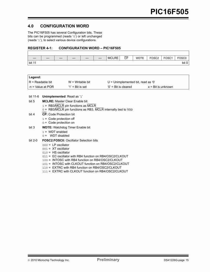
4.0 CONFIGURATION WORDThe PIC16F505 has several Configuration bits. Thesebits can be programmed (reads ‘0’) or left unchanged(reads ‘1’), to select various device configurations.
REGISTER 4-1: CONFIGURATION WORD – PIC16F505
— — — — — — MCLRE CP WDTE FOSC2 FOSC1 FOSC0
bit 11 bit 0
Legend:R = Readable bit W = Writable bit U = Unimplemented bit, read as ‘0’-n = Value at POR ‘1’ = Bit is set ‘0’ = Bit is cleared x = Bit is unknown
bit 11-6 Unimplemented: Read as ‘1’bit 5 MCLRE: Master Clear Enable bit
1 = RB3/MCLR pin functions as MCLR0 = RB3/MCLR pin functions as RB3, MCLR internally tied to VDD
bit 4 CP: Code Protection bit1 = Code protection off0 = Code protection on
bit 3 WDTE: Watchdog Timer Enable bit 1 = WDT enabled0 = WDT disabled
bit 2-0 FOSC2:FOSC0: Oscillator Selection bits000 = LP oscillator001 = XT oscillator010 = HS oscillator 011 = EC oscillator with RB4 function on RB4/OSC2/CLKOUT100 = INTOSC with RB4 function on RB4/OSC2/CLKOUT 101 = INTOSC with CLKOUT function on RB4/OSC2/CLKOUT110 = EXTRC with RB4 function on RB4/OSC2/CLKOUT111 = EXTRC with CLKOUT function on RB4/OSC2/CLKOUT
2010 Microchip Technology Inc. Preliminary DS41226G-page 15
PIC16F505
5.0 CODE PROTECTIONFor the PIC16F505, once code protection is enabled,program memory locations 0x040-0x3FE inclusive,read all ‘0’s. Program memory locations 0x000-0x03Fand 0x3FF are always unprotected. The user IDlocations, backup OSCCAL location and the Configura-tion Word read out in an unprotected fashion. It ispossible to program the user ID locations, backupOSCCAL location and the Configuration Word aftercode-protect is enabled.
5.1 Disabling Code ProtectionIt is recommended that the following procedure beperformed before any other programming is attempted.It is also possible to turn code protection off (CP = 1)using this procedure. However, all data within theprogram memory will be erased when thisprocedure is executed, and thus, the security of thecode is not compromised.To disable code-protect:
a) Enter Program mode.b) Execute Bulk Erase Program Memory
command (001001).c) Wait TERA.
5.2 Embedding Configuration Word and User ID Information in the Hex File
5.3 Checksum Computation
5.3.1 CHECKSUMChecksum is calculated by reading the contents of thePIC16F505 memory locations and adding up theopcodes up to the maximum user addressable location(e.g., 0x3FF for the PIC16F505). Any carry bitsexceeding 16 bits are neglected. Finally, the Configura-tion Word (appropriately masked) is added to thechecksum. Checksum computation for the PIC16F505is shown in Table 5-1.
The checksum is calculated by summing the following:
• The contents of all program memory locations• The Configuration Word, appropriately masked• Masked ID locations (when applicable)
The Least Significant 16 bits of this sum is thechecksum.
The following table describes how to calculate thechecksum for each device.
Note: To allow portability of code, theprogrammer is required to read theConfiguration Word and user ID locationsfrom the hex file when loading the hex file.If Configuration Word information was notpresent in the hex file, then a simplewarning message may be issued.Similarly, while saving a hex file,Configuration Word and user IDinformation must be included. An option tonot include this information may beprovided.Microchip Technology Incorporated feelsstrongly that this feature is important forthe benefit of the end customer.
Note: The checksum calculation differsdepending on the code-protect setting.The Configuration Word and ID locationscan always be read regardless of thecode-protect settings.
DS41226G-page 16 Preliminary 2010 Microchip Technology Inc.

PIC16F505
TABLE 5-1: CHECKSUM COMPUTATIONS – PIC16F505(1)Device Code-Protect Checksum* BlankValue
0x723 at 0and MaxAddress
PIC16F505 OFF SUM[0x000:0x3FE] + CFGW & 0x03F 0xEC40 0xDA88ON SUM[0x00:0x3F] + CFGW & 0x03F + SUM_ID 0xEC2F 0xD19B
Legend: CFGW = Configuration WordSUM[a:b] = [Sum of locations a to b inclusive]SUM_ID = User ID locations masked by 0xF then made into a 16-bit value with ID0 as the Most Significant nibble.For example, ID0 = 0x1, ID1 = 0x2, ID2 = 0x3, ID3 = 0x4, then SUM_ID = 0x1234.*Checksum = [Sum of all the individual expressions] MODULO [0xFFFF]+ = Addition& = Bitwise AND
Note 1: Checksum shown assumes that SUM_ID contains the unprotected checksum.
2010 Microchip Technology Inc. Preliminary DS41226G-page 17
PIC16F505
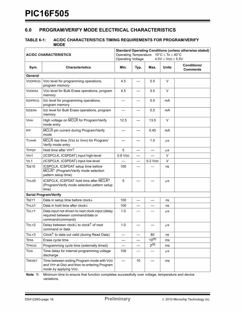
6.0 PROGRAM/VERIFY MODE ELECTRICAL CHARACTERISTICS
TABLE 6-1: AC/DC CHARACTERISTICS TIMING REQUIREMENTS FOR PROGRAM/VERIFY MODE
AC/DC CHARACTERISTICSStandard Operating Conditions (unless otherwise stated)Operating Temperature 10°C TA 40°COperating Voltage 4.5V VDD 5.5V
Sym. Characteristics Min. Typ. Max. Units Conditions/Comments
GeneralVDDPROG VDD level for programming operations,
program memory4.5 — 5.5 V
VDDERA VDD level for Bulk Erase operations, program memory
4.5 — 5.5 V
IDDPROG IDD level for programming operations, program memory
— — 0.5 mA
IDDERA IDD level for Bulk Erase operations, program memory
— — 0.5 mA
VIHH High voltage on MCLR for Program/Verify mode entry
12.5 — 13.5 V
IPP MCLR pin current during Program/Verify mode
— — 0.45 mA
TVHHR MCLR rise time (VSS to VIHH) for Program/Verify mode entry
— — 1.0 s
TPPDP Hold time after VPP 5 — — sVIH1 (ICSPCLK, ICSPDAT) input high-level 0.8 VDD — — VVIL1 (ICSPCLK, ICSPDAT) input low-level — — 0.2 VDD VTSET0 ICSPCLK, ICSPDAT setup time before
MCLR (Program/Verify mode selection pattern setup time)
100 — — ns
THLD0 ICSPCLK, ICSPDAT hold time after MCLR (Program/Verify mode selection pattern setup time)
5 — — s
Serial Program/VerifyTSET1 Data in setup time before clock 100 — — nsTHLD1 Data in hold time after clock 100 — — nsTDLY1 Data input not driven to next clock input (delay
required between command/data or command/command)
1.0 — — s
TDLY2 Delay between clockto clockof next command or data
1.0 — — s
TDLY3 Clock to data out valid (during Read Data) — — 80 nsTERA Erase cycle time — — 10(1) msTPROG Programming cycle time (externally timed) — — 2(1) msTDIS Time delay for internal programming voltage
discharge100 — — s
TRESET Time between exiting Program mode with VDD and VPP at GND and then re-entering Program mode by applying VDD.
— 10 — ms
Note 1: Minimum time to ensure that function completes successfully over voltage, temperature and device variations.
DS41226G-page 18 Preliminary 2010 Microchip Technology Inc.

PIC16F505
REVISION HISTORY
Revision G (02/2010)Revised Section 1.1; Added QFN pin diagram; RevisedNote 1, Table 1-1; Revised Section 3.1, 1st para;Added Revision History.
2010 Microchip Technology Inc. Preliminary DS41226G-page 19

PIC16F505
NOTES:DS41226G-page 20 Preliminary 2010 Microchip Technology Inc.

Note the following details of the code protection feature on Microchip devices:• Microchip products meet the specification contained in their particular Microchip Data Sheet.
• Microchip believes that its family of products is one of the most secure families of its kind on the market today, when used in the intended manner and under normal conditions.
• There are dishonest and possibly illegal methods used to breach the code protection feature. All of these methods, to our knowledge, require using the Microchip products in a manner outside the operating specifications contained in Microchip’s Data Sheets. Most likely, the person doing so is engaged in theft of intellectual property.
• Microchip is willing to work with the customer who is concerned about the integrity of their code.
• Neither Microchip nor any other semiconductor manufacturer can guarantee the security of their code. Code protection does not mean that we are guaranteeing the product as “unbreakable.”
Code protection is constantly evolving. We at Microchip are committed to continuously improving the code protection features of ourproducts. Attempts to break Microchip’s code protection feature may be a violation of the Digital Millennium Copyright Act. If such actsallow unauthorized access to your software or other copyrighted work, you may have a right to sue for relief under that Act.
Information contained in this publication regarding deviceapplications and the like is provided only for your convenienceand may be superseded by updates. It is your responsibility toensure that your application meets with your specifications.MICROCHIP MAKES NO REPRESENTATIONS ORWARRANTIES OF ANY KIND WHETHER EXPRESS ORIMPLIED, WRITTEN OR ORAL, STATUTORY OROTHERWISE, RELATED TO THE INFORMATION,INCLUDING BUT NOT LIMITED TO ITS CONDITION,QUALITY, PERFORMANCE, MERCHANTABILITY ORFITNESS FOR PURPOSE. Microchip disclaims all liabilityarising from this information and its use. Use of Microchipdevices in life support and/or safety applications is entirely atthe buyer’s risk, and the buyer agrees to defend, indemnify andhold harmless Microchip from any and all damages, claims,suits, or expenses resulting from such use. No licenses areconveyed, implicitly or otherwise, under any Microchipintellectual property rights.
2010 Microchip Technology Inc. Prelimin
Trademarks
The Microchip name and logo, the Microchip logo, dsPIC, KEELOQ, KEELOQ logo, MPLAB, PIC, PICmicro, PICSTART, PIC32 logo, rfPIC and UNI/O are registered trademarks of Microchip Technology Incorporated in the U.S.A. and other countries.
FilterLab, Hampshire, HI-TECH C, Linear Active Thermistor, MXDEV, MXLAB, SEEVAL and The Embedded Control Solutions Company are registered trademarks of Microchip Technology Incorporated in the U.S.A.
Analog-for-the-Digital Age, Application Maestro, CodeGuard, dsPICDEM, dsPICDEM.net, dsPICworks, dsSPEAK, ECAN, ECONOMONITOR, FanSense, HI-TIDE, In-Circuit Serial Programming, ICSP, Mindi, MiWi, MPASM, MPLAB Certified logo, MPLIB, MPLINK, mTouch, Octopus, Omniscient Code Generation, PICC, PICC-18, PICDEM, PICDEM.net, PICkit, PICtail, REAL ICE, rfLAB, Select Mode, Total Endurance, TSHARC, UniWinDriver, WiperLock and ZENA are trademarks of Microchip Technology Incorporated in the U.S.A. and other countries.
SQTP is a service mark of Microchip Technology Incorporated in the U.S.A.
All other trademarks mentioned herein are property of their respective companies.
© 2010, Microchip Technology Incorporated, Printed in the U.S.A., All Rights Reserved.
Printed on recycled paper.
ISBN: 978-1-60932-033-1
ary DS41226G-page 21
Microchip received ISO/TS-16949:2002 certification for its worldwide headquarters, design and wafer fabrication facilities in Chandler and Tempe, Arizona; Gresham, Oregon and design centers in California and India. The Company’s quality system processes and procedures are for its PIC® MCUs and dsPIC® DSCs, KEELOQ® code hopping devices, Serial EEPROMs, microperipherals, nonvolatile memory and analog products. In addition, Microchip’s quality system for the design and manufacture of development systems is ISO 9001:2000 certified.

DS41226G-page 22 Preliminary 2010 Microchip Technology Inc.
AMERICASCorporate Office2355 West Chandler Blvd.Chandler, AZ 85224-6199Tel: 480-792-7200 Fax: 480-792-7277Technical Support: http://support.microchip.comWeb Address: www.microchip.comAtlantaDuluth, GA Tel: 678-957-9614 Fax: 678-957-1455BostonWestborough, MA Tel: 774-760-0087 Fax: 774-760-0088ChicagoItasca, IL Tel: 630-285-0071 Fax: 630-285-0075ClevelandIndependence, OH Tel: 216-447-0464 Fax: 216-447-0643DallasAddison, TX Tel: 972-818-7423 Fax: 972-818-2924DetroitFarmington Hills, MI Tel: 248-538-2250Fax: 248-538-2260KokomoKokomo, IN Tel: 765-864-8360Fax: 765-864-8387Los AngelesMission Viejo, CA Tel: 949-462-9523 Fax: 949-462-9608Santa ClaraSanta Clara, CA Tel: 408-961-6444Fax: 408-961-6445TorontoMississauga, Ontario, CanadaTel: 905-673-0699 Fax: 905-673-6509
ASIA/PACIFICAsia Pacific OfficeSuites 3707-14, 37th FloorTower 6, The GatewayHarbour City, KowloonHong KongTel: 852-2401-1200Fax: 852-2401-3431Australia - SydneyTel: 61-2-9868-6733Fax: 61-2-9868-6755China - BeijingTel: 86-10-8528-2100 Fax: 86-10-8528-2104China - ChengduTel: 86-28-8665-5511Fax: 86-28-8665-7889China - ChongqingTel: 86-23-8980-9588Fax: 86-23-8980-9500China - Hong Kong SARTel: 852-2401-1200 Fax: 852-2401-3431China - NanjingTel: 86-25-8473-2460Fax: 86-25-8473-2470China - QingdaoTel: 86-532-8502-7355Fax: 86-532-8502-7205China - ShanghaiTel: 86-21-5407-5533 Fax: 86-21-5407-5066China - ShenyangTel: 86-24-2334-2829Fax: 86-24-2334-2393China - ShenzhenTel: 86-755-8203-2660 Fax: 86-755-8203-1760China - WuhanTel: 86-27-5980-5300Fax: 86-27-5980-5118China - XianTel: 86-29-8833-7252Fax: 86-29-8833-7256China - XiamenTel: 86-592-2388138 Fax: 86-592-2388130China - ZhuhaiTel: 86-756-3210040 Fax: 86-756-3210049
ASIA/PACIFICIndia - BangaloreTel: 91-80-3090-4444 Fax: 91-80-3090-4123India - New DelhiTel: 91-11-4160-8631Fax: 91-11-4160-8632India - PuneTel: 91-20-2566-1512Fax: 91-20-2566-1513Japan - YokohamaTel: 81-45-471- 6166 Fax: 81-45-471-6122Korea - DaeguTel: 82-53-744-4301Fax: 82-53-744-4302Korea - SeoulTel: 82-2-554-7200Fax: 82-2-558-5932 or 82-2-558-5934Malaysia - Kuala LumpurTel: 60-3-6201-9857Fax: 60-3-6201-9859Malaysia - PenangTel: 60-4-227-8870Fax: 60-4-227-4068Philippines - ManilaTel: 63-2-634-9065Fax: 63-2-634-9069SingaporeTel: 65-6334-8870Fax: 65-6334-8850Taiwan - Hsin ChuTel: 886-3-6578-300Fax: 886-3-6578-370Taiwan - KaohsiungTel: 886-7-536-4818Fax: 886-7-536-4803Taiwan - TaipeiTel: 886-2-2500-6610 Fax: 886-2-2508-0102Thailand - BangkokTel: 66-2-694-1351Fax: 66-2-694-1350
EUROPEAustria - WelsTel: 43-7242-2244-39Fax: 43-7242-2244-393Denmark - CopenhagenTel: 45-4450-2828 Fax: 45-4485-2829France - ParisTel: 33-1-69-53-63-20 Fax: 33-1-69-30-90-79Germany - MunichTel: 49-89-627-144-0 Fax: 49-89-627-144-44Italy - Milan Tel: 39-0331-742611 Fax: 39-0331-466781Netherlands - DrunenTel: 31-416-690399 Fax: 31-416-690340Spain - MadridTel: 34-91-708-08-90Fax: 34-91-708-08-91UK - WokinghamTel: 44-118-921-5869Fax: 44-118-921-5820
WORLDWIDE SALES AND SERVICE
01/05/10