physics/0606061 pdf - arxiv.org
TRANSCRIPT

1
On the production of flat electron bunches for laser wake
field acceleration
M. Kando, Y. Fukuda, H. Kotaki, J. Koga, S. V. Bulanov†, T. Tajima Kansai Photon Science Institute, Japan Atomic Energy Agency, Kyoto 619-0215, Japan
A. Chao, R. Pitthan
Stanford Linear Accelerator Center, Menlo Park, California 94025, USA
K.-P. Schuler DESY, Deutsches Elektronen Synchrotron, 22603 Hamburg, Germany
A. G. Zhidkov†, K. Nemoto
Central Research Institute of Electric Power Industry, Yokosuka, Kanagawa 240-0196, Japan
Abstract
We suggest a novel method for injection of electrons into the acceleration phase of
particle accelerators, producing low emittance beams appropriate even for the
demanding high energy Linear Collider specifications. In this paper we work out the
injection into the acceleration phase of the wake field in a plasma behind a high
intensity laser pulse, taking advantage of the laser polarization and focusing. With the
aid of catastrophe theory we categorize the injection dynamics. The scheme uses the
structurally stable regime of transverse wake wave breaking, when electron trajectory
self-intersection leads to the formation of a flat electron bunch. As shown in three-
dimensional particle-in-cell simulations of the interaction of a laser pulse in a line-
focus with an underdense plasma, the electrons, injected via the transverse wake wave
breaking and accelerated by the wake wave, perform betatron oscillations with
different amplitudes and frequencies along the two transverse coordinates. The
polarization and focusing geometry lead to a way to produce relativistic electron
bunches with asymmetric emittance (flat beam). An approach for generating flat laser
accelerated ion beams is briefly discussed.
† Also at A. M. Prokhorov Institute of General Physics of Russian Academy of Sciences, Moscow 119991, Russia.

2
1. Introduction
Electron accelerators with energies of many GeV and low emittance are needed for coherent
light sources and linear colliders. The laser acceleration of charged particles provides a promising
approach toward such development in a compact way, avoiding some of the complications which
arise for the additional requirements of asymmetric emittance for linear colliders, as outlined below.
In the Laser Wake Field Accelerator (LWFA), concept electrons are accelerated by the longitudinal
electric field created in an underdense plasma by a high intensity short pulse laser [1]. Electrons
injected by conventional accelerators, or self-injected by nonlinear wakewave breaking (see for
details a review article [2] and literature therein) achieve energies substantially higher than the
initial injection energies. Although the understanding and production of high intensity ( ºnC) and
low emittance (≈ 2-3 mm mrad) electron beams via laser plasma interaction has made rapid progress
in recent years [3,4-7], applications to coherent light sources and linear colliders still demand further
advances. A symmetric emittance of about 1mm-mrad is needed for coherent light sources to reach
X-ray wavelengths of 1 Ångstrom [8]. Linear electron-positron сolliders need asymmetric
emittances and polarized electrons, with the smaller vertical emittance required to be of the order of
0.1 mm-mrad. The asymmetric emittances (flat beam1) are needed to reduce the beam induced
synchrotron radiation (beamstrahlung) in the interaction (see below), and electron polarization is
required because the effective luminosity can be up to 2 orders of magnitude larger (depending on
the process), as shown by the SLD experiment at the Stanford Linear Collider (SLC) [9].
Additionally, positron beam polarization is desirable because certain processes can be measured
with higher signal-to-noise ratio due to the additional positron polarization, and it enables the
1 This paper addresses both laser-plasma and accelerator physics issues. One frequent confusion in the nomenclature is the use of the term “flat beam”. In accelerator physics flat beam means an asymmetric spot size (created with an asymmetric emittance). In laser physics a flat beam is one with a large focal length, and the means to achieve an asymmetric spot size is a “line focus”.

3
measurement of transverse cross sections [10]. The capability to selectively suppress unwanted
background processes is especially desired in search for new physics.
With the near-term aim of producing 1 GeV range laser accelerated electron bunches, a more
quantitative evaluation of differing requirements of major applications using GeV electrons is in
order. These requirements include, in order of rising beam quality, 1) fixed target – electron beam
interactions, 2) synchrotron and coherent light sources and 3) the colliding electron (positron) beam
configurations:
1. For fixed target applications the electron beam emittance is less important because the
luminosity is determined by the beam charge and the target thickness [11]. In this
application the electron polarization can play a role and enhance the effective luminosity.
2. In case of the GeV electron beam usage for coherent light sources, e. g. for linac light
sources, low emittance is important, because radiation from a high emittance beam fails
to be coherent. This application requires small emittances, of the order of 1 mm-mrad for
1Å wavelength, but a small spot size is not necessary.
3. For colliding electron beams, the emittance determines the minimum achievable spot size,
i.e. it is directly related to the maximum luminosity. Depending on the electron energy,
one needs a spot size approximately equal to 400 nm for 100 GeV electrons, and 5 nm
(small dimension) in the case of the 1 TeV collider [12]. Required for colliders in
addition are the electron beam polarization (80% or more) and flat beams with an aspect
ratio of about 100, in order to reduce beamstrahlung losses and electron-positron pair
production [9,13].
The conditions to have beams of high electric charge and low emittance are contradictory,
because space charge effects make the transverse emittance grow [14]. The emittance is calculated
as a product of the spot size, σx, and the divergence, σx′, both determined at a beam waist (or a pin
4
hole), i.e. the transverse emittance is ε = σx σx′. In addition, the normalized emittance, defined as εN
= γeε, is an adiabatic invariant under beam acceleration, where γe is the electron relativistic gamma
factor. The values of emittance quoted earlier refer to the normalized emittances.
If we consider LWFA produced electrons, we see femtosecond range electron bunches
accelerated to hundreds of MeV, and driven out of the plasma [3]. The energy spectrum is a quasi-
mono-energetic form [4-7,15], which is mainly related to the fact that fast electrons reach the
maximum energy and are localized at the top of the separatrix in the x,px phase plane [16-18]. We
remark two properties of LWFA ejected relativistic electrons: a) the product of the bunch length and
the energy spread, the longitudinal emittance, is comparable to conventional RF sources (in the
range of MeV-ps), while the very short bunch length is achieved even without bunch compression,
and b) the micron-size transverse spot of the initial electron bunch corresponds to the laser spot size,
which in turn may lead to a small transverse emittance. At present the emittance requirements,
including the asymmetry, are met with the use of expensive damping rings, which often yield long
bunches and therefore require subsequent bunch compressions. There is another R&D effort
underway to produce asymmetric beams using RF guns [19].
As recognized in Ref. [16], the electron injection into the acceleration phase of a wakefield takes
place due to nonlinear Langmuir wave wave-breaking. This breaking of the Langmuir wave, known
since J. Dawson’s publication in Ref. [20], has been studied theoretically and experimentally (see
Ref. [2] and literature therein). It is important to notice that the realization of resilience against
wave-breaking in the relativistic regime in the longitudinal direction led to the original LWFA
suggestion [1]. In the non-one-dimensional case and in the case of an inhomogeneous plasma
density the wake wave-breaking acquires features that allow manipulation of the injected electron
bunch parameters. For example, properties of the transverse wake wave-breaking [21] have been
used in Refs. [4,15,22] in order to explain nonlinear wake evolution and electron acceleration in
5
homogeneous and inhomogeneous plasmas. In addition, longitudinal breaking was invoked to
describe electron self-injection in homogeneous plasmas [23,24], and the controllable electron
injection regimes in plasmas with a tailored density profile [25].
In the present paper we shall formulate an approach for producing asymmetric emittance
electron bunches by using asymmetric laser pulse focusing for the laser wakefield acceleration,
when the transverse wake breaking leads to the formation of an electron bunch elongated along the
transverse direction.
2. Laser Line Focus
In present day chirped pulse amplification (CPA) based laser systems, laser pulses have a
Gaussian (TEM00)-like spatial profile. There are several schemes to achieve a line focus, which has
an asymmetric transverse spatial profile. One is using astigmatism on the sagittal plane of a
spherical mirror. This technique was applied to produce transient X-ray lasers. This scheme can
generate a large aspect ratio of 300:1; however, the focusing depth is limited and a time difference
for arriving at the focus arises [26]. A slightly misaligned off-axis parabolic mirror generates
astigmatism, resulting in an asymmetric focal spot. A toroidal mirror can be used. Here, we propose
to use a pair of reflective cylindrical mirrors. Cylindrical mirrors are easy to fabricate and cost-
saving. A large amount of astigmatism of cylindrical mirrors placed off-axis can be improved when
the incident angle is chosen properly. Further study is needed to examine the effect of effective
pulse elongation in time using these line focus techniques in the generation of wakefields.
3. Structure of Transverse Wake Wave Breaking
Due to the nonlinear dependence of the Langmuir wave frequency on its amplitude, caused
by the electron density redistribution along the laser pulse axis and by the relativistic dependence of
the Langmuir frequency on the kinetic energy of the electrons, surfaces of constant phase in the

6
wake wave give rise to a paraboloidal form [27]. The curvature of constant phase surfaces increases
with the distance from the laser pulse until the curvature radius R becomes comparable to the
electron displacementς in the wake, leading to electron trajectory self-intersection. This is the so-
called regime of transverse wake breaking, which leads to electron injection into the acceleration
phase [21]. Along the lines of Refs. [21, 28] we consider a wakefield plasma wave excited by a laser
pulse of finite width. The condition of the wake excitation determines wω and wk which are the
wake frequency and wavenumber, respectively, where w w gk vω = , and gv is the group velocity of
the driver laser pulse. The wake wave frequency, equal to the local value of the Langmuir
frequency, depends on the transverse coordinates, y and z. This dependence arises due to the plasma
outward motion caused by the laser pulse ponderomotive pressure and by the relativistic dependence
of the Langmuir frequency on the wave amplitude. The dependence on the wave amplitude is
determined by the laser pulse transverse shape, which can be approximated in the vicinity of the axis
as ( ) ( )2 20( , ) 1 / /y za y z a y s z s⎡ ⎤≈ − −⎢ ⎥⎣ ⎦
, i.e. in the transverse plane it has an elliptic form. The wake
frequency near the axis may be approximated by a simple form
( ) ( )2 2,0( , ) / /w w w y zy z y s z sω ω ω ⎡ ⎤≈ + ∆ +⎢ ⎥⎣ ⎦
, where ys and zs are related to the curvature radii in the
y and z directions, wω∆ is the difference between the Langmuir frequency outside and on the axis of
the wake field, ,0wω . From the expression of constant phase surfaces in the wake wave,
( , , , ) ( , )( / )w w gx y z t y z t x vψ ω= − = constant, it follows that their curvature increases with the
distance l from the laser pulse front, i. e. the curvature radii decrease as 2,0 / 2y w y wR s lω ω= ∆ and
2,0 / 2z w z wR s lω ω= ∆ with ,0/w g wl vψ ω= .
We write the equation for the constant phase surface in the form

7
2 20 0
0 0 0 0 0( , ) , (1)2 2 x y z
y z
y zy z y zR R
⎛ ⎞= + + +⎜ ⎟⎜ ⎟⎝ ⎠
M e e e
where ( , , )x y ze e e are the unit vectors along the x, y, and z axes. In the nonlinear wake the actual
position of the constant phase surface is given by the equation
0 0 0 0 0 0 0( , ) ( , ) ( , ). (2)y z y z y zς= +M M n
Here ς is the amplitude of the electron displacement and
0 0
0 0
0 0( , ) (3)y z
y z
y z∂ ×∂
=∂ ×∂
M Mn
M M
is the unit vector normal to the surface of constant phase. In the case when the surface is given by
Eq. (1) the normal vector is
1/ 22 2
0 0 0 00 0( , ) 1 . (4)x y z
y z y z
y z y zy zR R R R
−⎡ ⎤⎛ ⎞ ⎛ ⎞⎛ ⎞⎢ ⎥= + + + +⎜ ⎟ ⎜ ⎟⎜ ⎟⎜ ⎟ ⎜ ⎟⎢ ⎥⎝ ⎠⎝ ⎠ ⎝ ⎠⎣ ⎦
n e e e
Writing in the components Eq. (2), we obtain
( ) ( )
2 20 0
2 20 0
, (5)2 2 1 / /y z
y z
y zxR R y R z R
ς= + +
+ +
( ) ( )0
0 2 20 0
, (6)1 / /y y z
yy yR y R z R
ς= −
+ +
( ) ( )0
0 2 20 0
. (7)1 / /z y z
zz zR y R z R
ς= −
+ +
The mapping given by Eqs. (4) – (7) has a singularity when the Jacobian, 0 0( , ) / ( , )y z y z∂ ∂ ,
vanishes. Assuming the curvature radius in the z direction to be larger than in the y direction,

8
z yR R> , in the limit of a relatively small but finite values of 0 / yy R and 0 / zz R , we find that the
position of the singularity in the 0 0,y z plane is determined by the equation
( ) ( )2 20 02 2 3 / / . (8)y y zR y R z Rς ⎡ ⎤= − −⎢ ⎥⎣ ⎦
This equation has a solution if yRς ≥ , i. e. the displacement is larger than the radius of curvature.
For yRζ > the curve determined by Eq. (8) is an ellipse with the semi-axes 2( ) / 3y yR Rς ς− and
2( ) /z yR Rς ς− in the 0y and 0z directions, respectively.
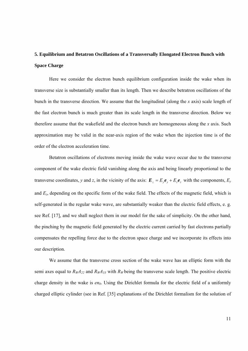
Plotting the surface in the , ,x y z space in which 0ς = is the paraboloid,
2 20 0/ 2 / 2y zx y R z R= + , 0 0,y y z z= = . With Eqs. (5)-(7) we obtain the constant phase surfaces for
cases 0ζ ≠ presented in Figs. 1 and 2.
In both cases, in Figs. 1 and 2, the projections of the constant phase surface onto the ,x y plane have
the form of a “swallow tail”. This corresponds to one of the forms of fundamental catastrophes (see.
[29]).
When the displacement value is in between the curvature radii, i.e. y zR Rς< < as in the case
shown in Fig. 1, the singularity in the ( , )y z plane is elongated along the z axis. On the other hand,
if y zR R ς< < , the singularity in the ( , )y z plane is elongated along the y axis, as shown in Fig. 2 c.
These types of singularities are typical, or, in other words, are structurally stable. In the 3D
configurations they correspond to the the transverse wave breaking with the injection into the
acceleration phase of flat electron bunches.
In the axially symmetric geometry when the curvature radii along the y and z directions equal
to each other, y zR R= , the injected electron bunch also has axial symmetry. However, this
configuration is not structurally stable and small perturbations of a general type transform it into a
9
structurally stable configuration with non-axially-symmetric electron bunch. We point out that in the
case of the gradual increase of the wake wave curvature the first breaking occurs under the condition
when the electron displacement becomes greater than the minimal curvature radius, e.g.
when y zR Rς< < , and the injected electron bunch is elongated along the minimal curvature direction
as in Fig. 1.
After the electron trajectory self-intersection has occurred, the injected electrons are
accelerated and they perform betatron oscillations in the transverse direction. This stage of the
electron bunch evolution is discussed below in Sections 4 and 5, where we present the results of the
particle-in-cell (PIC) simulations and the analytical theory of betatron oscillations when the effects
of the space charge are taken into account.
4. Results of Simulations of Transverse Wake Wave Breaking and Electron Bunch Injection
The paraboloidal structures of the wake plasma wave have been seen routinely in the three
dimensional particle-in-cell simulations of high intensity laser pulse propagation in underdense
plasmas, e. g. see Refs. [30, 31] where the laser pulse frequency upshifting has been discussed in
counter- and co-propagating two pulse interaction configurations. In Refs. [6, 31] 3D PIC
simulations distinctly show the “swallow tail” structure in the electron density distribution formed in
the nonlinear wake wave. In this Section we present 3D PIC simulation results for the electron
bunch injection, which clearly demonstrate the elongated electron bunch generation during the
transverse wake wave breaking. We use the electromagnetic relativistic PIC computer code
FPLaser3D [24], which exploits the moving window technique and the density decomposition
scheme of the current assignment with bell-shaped quasiparticles [32]; this weighting scheme
reduces significantly unphysical numerical effects of the standard PIC method.
10
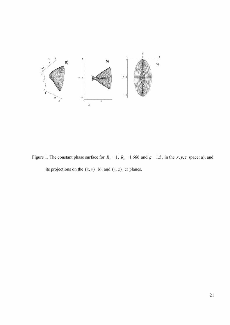
The flat electron bunch injection is seen in Fig. 3, where the results of the simulations of the
ultrashort laser pulse interaction with an underdense plasma target are shown. Here the linearly
polarized laser pulse with the electric field along the z direction and with wavelength λ=0.8 µm has
its intensity equal to I=1020 W/cm2. The pulse duration is 27 fs, and is focused into a spot with a
diameter of 16 µm. The laser pulse propagates along the x direction from the right to left in a plasma
with density ne=1019 cm-3. The simulations were performed with the use of “the moving window”
technique in a simulation box of size 80x56x56 λ3. The mesh sizes in the direction of the laser pulse
propagation and in the transverse direction are ∆x= λ/20 and ∆y=∆z= λ/10, respectively, with 8
particles (electrons and protons) per cell. In Fig. 3 where the electron density distribution in the z=0
plane: a); in the y=0 plane: b); and in the 315x ct λ+ = plane: c) are presented we distinctly see fast
electron bunches injected into the second period of the wake wave. The electron bunch width in the
z-direction is approximately two times larger than in the y-direction. The flat electron bunch
formation is also seen in Fig. 4, where the density distributions of fast electrons (with px>200 MeV)
in the z=0 plane: a); and in the y=0 plane are presented. We note here that electron oscillations in the
perpendicular directions, along the y and z axes, have different frequencies, as distinctly seen in
Fig.4.
In the case under consideration the transverse asymmetry of the wake breaking and the
electron bunch generation occurs in this case due to the effect of the linear polarization of the laser.
As found in Ref. [33] the linearly polarized laser pulse generates axially asymmetric self-focusing
channels and a wake with different amplitudes in the directions along and perpendicular to the
polarization direction. We note that the wake field accelerated electron bunches with the elliptic
form in the transverse direction have been observed in the experiments presented in Ref. [34], where
the transverse elongation has been attributed to the effects of linear polarization of the laser pulse-
driver.
11
5. Equilibrium and Betatron Oscillations of a Transversally Elongated Electron Bunch with
Space Charge
Here we consider the electron bunch equilibrium configuration inside the wake when its
transverse size is substantially smaller than its length. Then we describe betratron oscillations of the
bunch in the transverse direction. We assume that the longitudinal (along the x axis) scale length of
the fast electron bunch is much greater than its scale length in the transverse direction. Below we
therefore assume that the wakefield and the electron bunch are homogeneous along the x axis. Such
approximation may be valid in the near-axis region of the wake when the injection time is of the
order of the electron acceleration time.
Betatron oscillations of electrons moving inside the wake wave occur due to the transverse
component of the wake electric field vanishing along the axis and being linearly proportional to the
transverse coordinates, y and z, in the vicinity of the axis: y y z zE E⊥ = +E e e with the components, Ey
and Ez, depending on the specific form of the wake field. The effects of the magnetic field, which is
self-generated in the regular wake wave, are substantially weaker than the electric field effects, e. g.
see Ref. [17], and we shall neglect them in our model for the sake of simplicity. On the other hand,
the pinching by the magnetic field generated by the electric current carried by fast electrons partially
compensates the repelling force due to the electron space charge and we incorporate its effects into
our description.
We assume that the transverse cross section of the wake wave has an elliptic form with the
semi axes equal to RWA22 and RWA33 with RW being the transverse scale length. The positive electric
charge density in the wake is en0. Using the Dirichlet formula for the electric field of a uniformly
charged elliptic cylinder (see in Ref. [35] explanations of the Dirichlet formalism for the solution of

12
the Poisson equation in the confocal ellipsoidal coordinates), we write for the transverse electric
field originating from the electric charge separation inside the wake:
( )033 22
22 33
4 . (9)WF WFy y z z y z
enE E A y A zA Aπ
+ = ++
e e e e
Within the framework of the test particle approximation, when we can neglect the effects of
the electric and magnetic field produced by the fast electron bunch, the relativistic electron motion
in the electric field given by Eq. (9) corresponds to the betatron oscillations. It is easy to obtain that
the oscillations are performed along the y and z axes with the frequencies
33 221 2
22 33 22 33
, , (10)b bA A
A A A Aω ω ω ω= =
+ +
which have different values for the oscillations along the y , 1ω , and z axes, 2ω , respectively. Here
/b pe eω ω γ= with the electron gamma factor, eγ , and the Langmuir frequency 204 /pe en e mω π= .
The structure of the mode is given by the relationships:
1, 122
33 2, 2
exp( ), (11)
exp( )
C i ta
a C i t
ωδ
δ ω
±±
±±
⎛ ⎞±⎛ ⎞⎜ ⎟⎜ ⎟ = ⎜ ⎟⎜ ⎟ ±⎜ ⎟ ⎜ ⎟⎝ ⎠ ⎝ ⎠
∑∑
where 1,C ± and 2,C ± are constants determined by initial conditions. Here and below we assume for
the sake of simplicity that the electron gamma factor, eγ , does not depend on time. The time
dependence of eγ can easily be incorporated into our model as similarly done in Ref. [17], where
the betatron oscillations have been studied assuming axial symmetry of the wake and electron bunch.
Now we take into account the space charge effects which generate electric and magnetic
fields from the electron bunch. As has been done above, in order to find the electric and magnetic
fields b⊥E and b
⊥B generated by the elliptic cylindrical electron bunch, we use the Dirichlet formulae.
We cast these into the form

13
( ) ( )33 22222 33
4 , (12)b b by y z z y z
b
eNE E a y a zr a a
+ = ++
e e e e
and
( ) ( )33 22222 33
4 . (13)b b b by y z z y z
b
eN vB B a z a yr c a a
+ = −+
e e e e
Here rb a22 and rb a33 are the electron bunch semi-axes in the transverse plane, vb and Nb are the
electron velocity along the x axis and the number of electrons per unit length, and rb is a typical
transverse size of the bunch.
The equations of the motion of a fluid element of the electron bunch in the transverse
direction are
( ) 0, (14)t b bn n⊥ ⊥∂ +∇ =v
( ) ( / ). (15)t t e c⊥ ⊥ ⊥ ⊥ ⊥ ⊥∂ + ⋅∇ = + ×p v p E v B
Here the electron density, ( , , )bn y z t , and transverse component of the electron momentum
( , , ) ( , , ) ( , , )y y z zy z t p y z t p y z t⊥ = +p e e depend on the coordinates, y,z, and time, t. The operator ⊥∇
is given by y y z z⊥∇ = ∂ + ∂e e .
For the electric and magnetic fields linearly dependent on the coordinates, as given by
Equations (9,12,13), the equations of the bunch motion admit a self-similar solution, which
describes the fluid motion with homogeneous deformation [36]. Within the framework of the
homogeneous deformation approximation, the relationship between the Euler, ix , and Lagrange
coordinates, 0ix , has the form
0( ) , (16)i ij jx a t x=
where ija is a deformation matrix with time dependent components. A summation over repeating
indices is assumed. Differentiating this relationship with respect to time, we find that the velocity of

14
the electron fluid element is given by ( )i ij jv w t x= with 1ij ik kjw a a−= . Here 1
kja− is the inverse matrix to
the matrix ija . A kinematical interpretation of the velocity gradient matrix ijw is provided by
analyzing the relative motion of two neighboring fluid particles [37]. The particles we consider are
separated by ixδ . The relative velocity ivδ can be written as
i j i j ij j ij j ij jv v x w x x xδ δ δ δ δ= ∂ = = Ξ +Ω . Here i y y z z∂ = ∂ + ∂e e ; the tensors ijΞ and ijΩ are
determined by ( ) / 2ij j i i jv vΞ = ∂ + ∂ and ( ) / 2 / 2ij j i i j ijk kv v ε ωΩ = ∂ −∂ = − with ijkε being the
antisymmetric Ricci tensor. The vector kω is the fluid vorticity = ∇×vω . The term ij jxδΞ describes
pure straining motion, while ij jxδΩ describes rigid body rotation.
In the approximation | xp⊥| p the transverse component of the momentum can be
written as ( )e e y y z zm v vγ⊥ = +p e e with the gamma factor, 2 2 1/ 2(1 / )e bv cγ −= − , calculated for the
longitudinal energy of fast electrons. In this case we obtain 0,t i e e ij j e e ij jp m w x m a xγ γ= ≡ .
Further we shall consider the case of curl free motion, 0⊥ ⊥∇ × =p , i. e. the matrix ijΩ
vanishes ( 0ijΩ = ). This corresponds to the diagonal form of the deformation matrix:
22 33diag1, , ija a a= . Assuming the electron density to be homogeneous and substituting the
expression ( )i ij jv w t x= with 1ij ik kjw a a−= for the electron velocity to the continuity equation Eq. (13),
we find that the electron density inside the bunch is given by
det (0)( ) (0) (17)
det ( )ij
b bij
an t n
a t⎛ ⎞
= ⎜ ⎟⎜ ⎟⎝ ⎠
with det ija being the determinant of the matrix ija . In the case under consideration it equals 22 33a a .
In order to illustrate the property of the motion with homogeneous deformation, we consider
the simplest example of the dynamics of a pressure-less gas for which the deformation matrix obeys

15
the equation 0ija = with initial conditions ij ija δ= and (0) (0)ij ija w= . The solution to this equation
is (0)ij ij ija w tδ= + . The catastrophe corresponds to the situation when the determinant of the matrix
ija vanishes. If the initial matrix of the fluid velocity gradients is diagonal,
22 33(0) diag1, (0), (0)ijw w w= , the deformation matrix is equal to
22 33( ) diag1,1 (0) ,1 (0) ija t w t w t= + + . Its determinant is 22 33det ( ) (1 (0) )(1 (0) )ija t w t w t= + + . A
singularity occurs when either 221/ (0)t w= − or 331/ (0)t w= − . The singularity occurs as a line in
3D space for 22 (0)w and 33 (0)w being equal and both negative, and singularity appears as a surface
in 3D space when just one value among 22 (0)w and 33(0)w is negative. The generic case
corresponds to the situation when just one value among 22 (0)w and 33(0)w is negative. This means
that in the generic case the singularity develops as a surface. We note that such type of singularity
on a surface has been studied in detail in applications for the nonlinear dynamics of gravitational
instability [38] and in the theory of magnetic field line reconnection in high conductivity plasmas
[39].
Since the number of electrons per unit length of the elliptical cylinder with the semi-axes
a= 22br a and b= 33br a is equal to 222 33b b bN n r a aπ= we can rewrite Eq. (17) as 2
22 33/b b bn N r a aπ= .
From Eqs. (9,12,13,15,17) we obtain for the matrix ija components a system of ordinary differential
equations
( ) ( )2
33 0 2222 2 2
22 33 22 33
4 , (18)b
e e b e
A n a Neam A A r a aπγ π γ
⎡ ⎤= − −⎢ ⎥
+ +⎢ ⎥⎣ ⎦
( ) ( )2
22 0 3333 2 2
22 33 22 33
4 . (19)b
e e b e
A n a Neam A A r a aπγ π γ
⎡ ⎤= − −⎢ ⎥
+ +⎢ ⎥⎣ ⎦

16
We see similarity between these equations and the equations for the charged particle beam dynamics
in the high energy accelerators, which are obtained within the framework of the Kapchinskij –
Vladimirskij approximation [40] (e. g. see Refs. [41,42]).
Using notations, 22ba r a= , 33bb r a= , ( )2 22 0 33 22 334 / e eK n e A m c A Aπ γ= + ,
( )2 23 0 22 22 334 / e eK n e A m c A Aπ γ= + , and incorporating the transverse emittance effects, we rewrite
equations (18, 19) as
22
2 3'' , (20)a K aa a bε ξ
+ = ++
23
3 3'' . (21)b K bb a bε ξ
+ = ++
Here 2ε and 3ε are the transverse emittance values in the y and z directions, 2 20/b b eN n rξ π γ= is a
dimensionless space charge parameter, and the primes denote differentiation with respect to the
variable s ct= . Properties of this equation system are discussed in detail in Ref. [40].
Equations (20,21) can be cast into the Hamiltonian form with the Hamiltonian depending on
the canonical coordinates a and b , and on the canonical momenta 2π and 3π . It reads
( )22
2 2 2 2 322 3 2 3 2 3 2 2
1( , , , ) ln (22)2
a b K a K b a ba b
εεπ π π π ξ⎛ ⎞
= + + + + + − +⎜ ⎟⎝ ⎠
H
from which we may conclude that for 0, 0a b> > the bunch performs nonlinear oscillations
around the equilibrium. In Fig. 5 we plot iso-contours of the potential function,
( )22
2 2 322 3 2 2
1( , ) ln , (23)2
a b K a K b a ba b
εε ξ⎛ ⎞
Π = + + + − +⎜ ⎟⎝ ⎠

17
for 2 3 2 32.5, 5, 1, 1, 1K K ε ε ξ= = = = = in frame a), and for 2 3 2 31, 2.25, 1, 1, 5K K ε ε ξ= = = = = in
frame b). From the form of the potential function, ( , )a bΠ , we can see that in general case the
frequencies of the oscillations along the y- and z-directions are different and depend on the
oscillation amplitudes. If the emittances, 2ε and 3ε , which are determined by the injection
mechanism, vanish, as in Fig. 5 b), the iso-contours of the function ( , )a bΠ can intersect the axis
a=0 or b=0. This corresponds to the case when in nonlinear oscillations one semi-axis of the bunch
becomes equal to zero and formally the bunch aspect ratio tends to infinity. We note that in the
axially symmetric configuration the space charge effect prevents the bunch radius from vanishing.
For a flat electron beam the space charge effects are not strong enough and the bunch
demagnification in one of the directions becomes possible.
The transverse equilibrium of the electron bunch in the wake corresponds to the local
minimum of the function ( , )a bΠ given by Eq. (23). It is given by a static solution of Eqs. (20,21)
for which the terms on the right hand sides vanish. We consider the case when the emittances
vanish. Solving these algebraic equations assuming 2 0ε = and 3 0ε = , we obtain for the equilibrium
32
3 2
, . (24)eq eq KKa bK K
ξ ξ= =
We point out that in equilibrium the electron bunch has an elliptic cross section with the aspect ratio
/eq eqa b equal to the aspect ratio of the wake: 22 33/ /eq eqa b A A= . The electron density inside the
bunch in the equilibrium is equal to
202 . (25)eq b
b eb
Nn nr ab
γπ
= =
It is by a factor 2eγ greater than the ion density in the plasma. The characteristic transverse size of
the bunch, br , can be found to be

18
20
, (26)bb
e
Nrnπ γ
=
i. e. the dimensionless space charge parameter, 2 20/b b eN n rξ π γ= , for the equilibrium configuration is
equal to unity, 1ξ = .
Using the definition (26) for the transverse size of the bunch, br , and linearizing equations
(20,21) in the vicinity of the equilibrium solution (24) for 2 0ε = and 3 0ε = ,
22 33 33 22/ , /eq eqa A A b A A= = , i.e. representing the functions a and b in the form eqa a aδ= + ,
eqb b bδ= + with a aδ , b bδ , we obtain
( ) ( ) ( )2 33 22 33 22 33
2 222 33 22 33 22 33
, (27)bA A A A Aa a b
A A A A A Aδ ω δ δ
⎧ ⎫⎡ ⎤⎪ ⎪= − + +⎢ ⎥⎨ ⎬+ + +⎢ ⎥⎪ ⎪⎣ ⎦⎩ ⎭
( ) ( ) ( )2 22 33 22 3322
2 222 3322 33 22 33
. (28)bA A A AAb a b
A AA A A Aδ ω δ δ
⎧ ⎫⎡ ⎤⎪ ⎪= − + +⎢ ⎥⎨ ⎬++ +⎢ ⎥⎪ ⎪⎣ ⎦⎩ ⎭
These equations describe oscillations with frequencies
22 331 2
22 33
2, . (29)b bb b
A AA A
ω ω ω ω= =+
As we see, in the case 22 33A A the frequency 2bω is much lower than 1
bω . We also see that the
frequency values in the case when the space charge effect is taken into account, Eq. (29), are
different from the frequencies, Eq. (10), obtained within the framework of the test particle
approximation.
The structure of the mode is described by the relationships:
19
( )1, 133 22
2 222 33 2, 222 33
exp( )1 , (30)
exp( )
b
b
C i tA Aa
b A A C i tA A
ωδ
δ ω
±±
±±
⎛ ⎞±⎛ ⎞⎛ ⎞ ⎜ ⎟⎜ ⎟⎜ ⎟ = ⎜ ⎟⎜ ⎟⎜ ⎟ − ±+ ⎜ ⎟⎜ ⎟⎝ ⎠ ⎝ ⎠⎝ ⎠
∑∑
where 1,C ± and 2,C ± are constants given by initial conditions. This expression corresponds to the
squinted ellipse form of the potential energy iso-contours in the vicinity of the bunch equilibrium
position presented in Fig. 5 b).
6. Discussion and Conclusion
In conclusion, a method is suggested for electron injection via the transverse wake wave
breaking, when the electron trajectory self-intersection leads to the formation of an electron bunch
elongated in the transverse direction. In this scheme we take advantage of the laser pulse focussed
into an elongated spot. In turn, this results in a wakefield generation that is localized in the axially
non-symmetric region with the components of the transverse electric field not equal to each other.
With the aid of catastrophe theory we demonstrate that a structurally stable regime of transverse
wake breaking leads to the transversally elongated electron bunch generation. Three-dimensional
particle-in-cell simulations of the laser pulse interaction with an underdense plasma show that
electrons, injected via the transverse wake wave breaking, form a bunch with an aspect ratio larger
than unity. Electrons accelerated by the wake perform betatron oscillations with different
amplitudes and frequencies along the two transverse coordinates. An exact analytical solution of the
electron hydrodynamics equations demonstrates the space charge effects, which modify the electron
bunch equilibrium and the frequencies and structure of the mode of betatron oscillations.
For a typical total number of electrons in the bunch accelerated by the wake equal to 1010totN = , which corresponds to the charge 1.6 nC, and a bunch length of 10 mµ , the electron
number per unit length is 13 110bN cm−= . If the plasma density and electron gamma factor are
19 30 10n cm−= and 5eγ = 00, expression (26) yields that the bunch size in the transverse direction is
approximately equal to 0.01br mµ≈ . Betatron frequencies, Eq. (29), in this case are 14 11 10b sω −≈
and 13 12 1.4 10b sω −≈ × , if we assume that the aspect ratio, 22 33/A A , equals 100.

20
One of the most important applications of laser produced relativistic electrons is to generate
positron bunches for their injection into conventional accelerators. To obtain polarized positron
beams an additional circularly polarized laser pulse (counterpropagating with the electron bunch)
may be used to generate longitudinally polarized gamma ray photons, which then collide with a thin
film target [43].
The emittance of laser accelerated ions can also be manipulated by changing the structure of
either the target irradiated by the laser pulse or the form of the focusing system. In the first case we
refer to the double layer target proposed in Ref. [44] in order to produce beams with controlled
quality, and studied in detail via computer simulations [45] and experiments [46]. Ref. [44]
proposed to use two-layer targets in which the first layer consists of heavy multicharged ions and the
second layer (thin and narrow in the transverse direction) consists of light ions (e.g. protons). If the
thin proton layer is elongated in one direction it will result in the generation of a flat proton beam. A
more complex form of the proton layer may be used in order to provide a uniform irradiation of the
target, which is required in the applications of the laser accelerated ions for hadron therapy. The
second case uses an ion focusing technique corresponding to a thin hollow cylindrical shell
irradiated by a femtosecond high-power laser pulse when the ion bunch flies through it. As
demonstrated in the experiments presented in Ref. [47], this technique allows one to simultaneously
focus the proton beam and to cut it onto quasi-monoenergetic beamlets. The use of an elliptical
cylinder shell provides a way for the transverse emittance manipulation. In addition, a phase rotator,
which also produces quasi-monoenergetic ion beamlets [48], when its transverse electric field is
made anisotropic, can produce flat ion beams.
Acknowledgments
This work is supported by the Ministry of Education, Science, Sports and Culture, Grand-in-
Aid for Specially Promoted Research No. 15002013. One of the authors (M. K.) is supported by the
Ministry of Education, Science, Sports and Culture, Grant-in-Aid for Young Scientists (B), No.
17740272, 2005.
21
Figure 1. The constant phase surface for 1yR = , 1.666zR = and 1.5ς = , in the , ,x y z space: a); and
its projections on the ( , )x y : b); and ( , )y z : c) planes.

22
Figure 2. The constant phase surface for 1yR = , 1.666zR = and 2ς = , in the , ,x y z space: a); and
its projections on the ( , )x y : b); and ( , )y z : c) planes.
23
Figure 3. Results of the 3D PIC simulations: the electron density distribution in the z=0 plane: a); in
the y=0 plane: b); and in the 315x ct λ+ = plane: c).

24
Figure 4. Fast electron (with px>200 MeV) density distribution in the z=0 plane: a); and in the y=0
plane.

25
Figure 5. Iso-contours of the potential function ( , )a bΠ for a) 2 3 2 32.5, 5, 1, 1, 1K K ε ε ξ= = = = = ,
and b) for 2 3 2 31, 2.25, 1, 1, 5K K ε ε ξ= = = = = .

26
References
[1] T. Tajima and J. M. Dawson, Phys. Rev. Lett. 43, 267 (1979).
[2] G. Mourou, T. Tajima, and S. V. Bulanov, Rev. Mod. Phys. 78, 309 (2006).
[3] K. Nakajima, D. Fisher, T. Kawakubo, et al., Phys. Rev. Lett. 74, 4428 (1995);
A. Modena, Z. Najmudin, A. E. Dangor, et al., Nature (London) 377, 606 (1995);
V. Malka, S. Fritzler, E. Lefebvre, et al., Science 298, 1596 (2002) ;
D. Umstadter, J. Phys. D 36, R151 (2003).
[4] S. P. D. Mangles, C. D. Murphy, Z. Najmudin, et al., Nature (London) 431, 535 (2004).
[5] C. G. R. Geddes, Cs. Toth, J. van Tilborg, et al., Nature (London) 431, 538 (2004).
[6] J. Faure, Y. Glinec, A. Pukhov, et al., Nature (London) 431, 541 (2004).
[7] K. Koyama, E. Miura, S. Kato, et al., J. Particle Accel. Soc.of Japan 1, 158 (2004).
[8] See for example Linac Coherent Light Source Conceptual Design Report, SLAC-R-593, April
2002, UC-414.
[9] Superconducting Electron-Positron Linear Collider Technical Design Report, DESY Laboratory
report, http://tesla.desy.de/new_pages/TDR_CD/start.html; The International Linear Collider
Global Design Effort Baseline Configuration Document, http://www.linearcollider.org/wiki/.
[10] G. Mortgaat-Pick et al., “The role of polarized positrons and electrons in revealing fundamental
interactions at the Linear Collider”, arXiv:hep-ph/0106155 v1 14 Jun 2001
[11] K. S. Kumar, R. Roy, P. E. Reimer, M. Strovink, “The Future of Fixed Target Physics:
Snowmass E5 Working Group Summary”, eConfC010630, SLAC-R-599, eProceedings of
Snowmass 2001; R. Pitthan, “Fixed Target e- Physics at the NLC, Snowmass 2001”,
http://www-project.slac.stanford.edu/lc/local/Fixed_Target/Pitthan_NLC_Fixed_Target.pdf
[12] R. Pitthan, “Emittance Needs of Future Accelerators”, Snowmass 2001,http://www-
project.slac.stanford.edu/lc/local/XFel/FutureEmitNeeds.pdf

27
[13] T. Raubenheimer and F. Zimmermann, Rev. Mod. Phys. 72, 95 (2000).
[14] A. Chao, R. Pitthan, T. Tajima, and A. Yeremian, Phys. Rev. ST Accel. Beams 6, 024201
(2003).
[15] A. Yamazaki, H. Kotaki, I. Daito, et al., Phys. Plasmas 12, 093101 (2005);
T. Hosokai, K. Kinoshita, T. Ohkubo, et al., Phys. Rev. E 73, 036407 (2006);
B. Hidding, K.-U. Amthor, B. Liesfeld, et al., Phys. Rev. Lett. 96, 105004 (2006);
M. Mori, M. Kando, I. Daito, et al., 2006, ArXiv Physics e-prints, arXiv:physics/0605178;
L. M. Chen, H. Kotaki, K. Nakajima, et al., 2006, ArXiv Physics e-prints,
arXiv:physics/0605240.
[16] S. V. Bulanov and T. Tajima, J. Particle Accel. Soc. of Japan 2, 111 (2005).
[17] S. V. Bulanov, M. Yamagiwa, T. Zh. Esirkepov, et al., Phys. Plasmas 12, 073103 (2005);
S. V. Bulanov, M. Yamagiwa, T. Zh. Esirkepov, et al., Plasma Phys. Rep. 32, 263 (2006).
[18] T. Esirkepov, S.V. Bulanov, M. Yamagiwa, and T. Tajima, Phys. Rev. Lett. 96, 014803 (2006).
[19] D. Edwards et al., “Status of Flat Electron Beam Production”, 2001 Particle Accelerator
Conference, http://accelconf.web.cern.ch/AccelConf/p05/PAPERS/WPAP035.PDF
[20] J. M. Dawson, Phys. Rev. 133, 383 (1959).
[21] S. V. Bulanov, F. Pegoraro, A. M. Pukhov, and A. S. Sakharov, Phys. Rev. Lett. 78, 4205
(1997).
[22] T. V. Liseikina, F. Califano, V. A. Vshivkov, F. Pegoraro, and S. V. Bulanov, Phys. Rev. E 60,
5991 (1999);
A. Pukhov and J. Meyer-ter-Vehn, Appl. Phys. B 74, 355 (2002);
H. Xu, W. Yu, P. Lu, et al., Phys. Plasmas. 12, 013105 (2005).
[23] S. V. Bulanov, et al., JETP Lett. 53, 565 (1991);
S. V. Bulanov, et al., Phys. Fluids B 4, 1935 (1992);

28
C. A. Coverdale, et al., Phys. Rev. Lett. 74, 4659 (1995);
D. Gordon, et al., Phys. Rev. Lett. 80, 2133 (1998).
[24] A. Zhidkov, et al., Phys. Rev. E 69, 035401(R) (2004).
[25] S. V. Bulanov, N. M. Naumova, F. Pegoraro, and J. Sakai, Phys. Rev. E 58, R5257 (1998);
H. Suk, N. Barov, J. B. Rosenzweig, and E. Esarey, Phys. Rev. Lett. 86, 1011 (2001).
[26] N. Hasegawa et al., JAERI Review 2001-003, p.31 (2001); I. N. Ross et al., Applied Optics 26,
1854 (1987).
[27] S. V. Bulanov and A. S. Sakharov, JETP Lett. 54, 203 (1991).
[28] S. V. Bulanov, F. Califano, G. I. Dudnikova, et al., Plasma Phys. Reports 25, 468 (1999).
[29] T. Poston and Y. Steward, Catastrophe Theory and its Applications (Pitman, London, 1978).
[30] S. V. Bulanov, T. Zh. Esirkepov, T. Tajima, Phys. Rev. Lett. 91, 085001 (2003).
[31] C. D. Murphy, et al., Phys. Plasmas 13, 033108 (2006).
[32] T. Zh. Esirkepov, Comput. Phys. Commun. 135, 144 (2001).
[33] A. Macchi, S. V. Bulanov, F. Califano, et al., in: Proc. of 42nd Annual Meeting of the APS
Division of Plasma Physics and 10th Int. Congress on Plasma Physics. Québec City, 2000.
Book of Abstracts, Paper MP1.065.
[34] S. P. D. Mangles, A. G. R. Thomas, M. C. Kaluza, et al., Phys. Rev. Lett. 96, 215001 (2006).
[35] S. Chandrasekhar, Ellipsoidal Figures of Equilibrium (Yale University, New Haven, 1969);
L. D. Landau and E. M. Lifshitz, Electrodynamics of Continuous Media ( Pergamon, New
York, 1960).
[36] L. I. Sedov, Similarity and Dimensional Methods in Mechanics (New York: Academic, 1959).
[37] G. K. Batchelor, An introduction to fluid mechanics (Cambridge University Press, Cambridge,
1967).
[38] Ya. B. Zel’dovich, Astron. Astrophys. 5, 84 (1970);
Ya. B. Zel’dovich and I. D. Novikov, The Structure and Evolution of the Universe (The
University of Chicago Press, Chicago and London; 1983).

29
[39] V. S. Imshennik and S. I. Syrovatskii, Sov. Phys. JETP 52, 900 (1967);
S. V. Bulanov and M. A. Ol’shanetskij, Sov. J. Plasma Phys. 11, 425 (1985);
T. Tajima and J.-I. Sakai, Sov. J. Plasma Phys. 15, 606 (1989);
S. V. Bulanov and J.-I. Sakai, Astrophys. J. Suppl. Ser. 117, 599 (1998).
[40] I.M. Kapchinskij and V.V. Vladimirskij, in Proceedings of the 2nd International Conference on
High Energy Accelerators and Instruments (CERN, Geneva, 1959), p. 274.
[41] A.W. Chao, Physics of Collective Beam Instabilities in High Energy Accelerators (John Wiley
and Sons, New York, 1993).
[42] S. Humphries, Jr., Charged Particle Beams (John Wiley and Sons. New York, 1990).
[43] T. Omori, M. Fukuda, T. Hirose, et al., Phys. Rev. Lett. 96, 114801 (2006).
[44] S. V. Bulanov, V.S. Khoroshkov, Plasma Phys. Rep. 28, 453 (2002).
[45] S. V. Bulanov, T. Zh. Esirkerov, V. S. Khoroshkov, et al., Phys. Lett. A 299, 240 (2002);
T. Zh. Esirkerov, S. V. Bulanov, K. Nishihara, et al., Phys. Rev. Lett. 89, 175003 (2002);
S.V. Bulanov, T.Zh. Esirkepov, F.F. Kamenets, et al., Plasma Phys. Rep. 28, 975 (2002);
E. Fourkal, I. Velchev, C.-M. Ma, Quantum Electronics and Laser Science Conference, Vol.
3, p. 1822 (2005).
[46] C. Schwoerer, et al., Nature 439, 445 (2006).
[47] T. Toncian, M. Borghesi, J. Fuchs, et al., Science 312 (5772), 410 (2006);
M. Dunne, Science 312 (5772), 374 (2006).
[48] A. Noda, S. Nakamura, Y. Iwashita, et al., Laser Physics 16, 647 (2006).