physics’ unit’3’ handbook’2011’ · pdf filephysics’...
TRANSCRIPT

Physics
Unit 3 Handbook 2011
ELECTRONICS & PHOTONICS MOTION MATERIALS AND THEIR USE IN STRUCTURES
Name:__________________________________

CGS Unit 3 Physics Page 2 Page 2
Term 1
Topics to be Covered Practical Activities & Other Tasks
Assessment
Week 1 Thurs 27th Jan Intro to Unit 3 – Course Outline Week 2 Mon 31st Jan Area of Study 2 – Electronics and Photonics
• Voltage, current, resistance, power, series and parallel circuits
• Basic voltage divider • Non-ohmic resistors such as LDR’s and
thermistors • learning to use a multimeter as a voltmeter,
ammeter and ohmmeter
• Prac 1: Using multimeter & DC circuits • Prac 2: Light dependent resistor (LDR) and
thermistor • Prac 3: Learning to use the CRO
Week 3 Mon 7th Feb • Properties of diodes • Properties of amplifier – Transfer curves, quiescent
point, input, biasing, linear gain of a voltage amplifier, inverting/non-inverting nature
• Prac 4: Diode • Prac 5: Light emitting diode (LED) • Prac 6: Demo: Using transistor as amplifier
Assignment 1
Week 4 Mon 14th Feb • Clipping and distortion • Optical-electrical and electrical-optical transducers
• Prac 7: Demo: Amplifiers continued • Prac 8: Photodiodes • Prac 9: Phototransistors
Week 5 Mon 21st Feb • Modulation
Assignment 2
Week 6 Mon 28th Feb Area of Study 1 – Motion in one and two dimensions
• Kinematics – algebraic and graphical • Vectors • Force vector diagrams • Newton’s three laws of motion
Assignment 3
Week 7
Mon 7th March (Quads 7th March Per 6-8)
• Momentum & Impulse • Work done by a force • Kinetic energy • Gravitational potential energy • Energy stored in an elastic medium
• Prac 1: Hookes law – F = -k�x SAC Test on Area of Study 2 (1p) – Electronics (3%)
Week 8 Tues 15th March (Mon 14th Labour Day)
• Isolated systems • Sticky collisions • Elastic & Inelastic collision
• Prac 2: Sticky collision – air track • Prac 3: Explosion – air track • Prac 4: Elastic collision – air track
Assignment 4
Week 9 Mon 21st March
• Projectile motion • Time to apex, time of flight, range • Effects of air-resistance
Assignment 5

CGS Unit 3 Physics Page 3 Page 3
Week 10 Mon 28th March
• Circular motion • Speed, velocity, acceleration and net force aspects
of circular motion in horizontal planes only
• Prac 5: Circular Motion
SAC Data analysis (1p) – Collisions (2%)
Week 11 Mon 4th April • Newtons law of Universal gravitation • Stable orbits for planets and man-made satellites • Geostationary orbits • Work done by gravity or against gravity in moving
objects from A to B in a gravitational field
Term 2 Topics to be Covered Practical Activities & Other Tasks
Assessment
Week 1 Wed 28th April (Easter 26th Anzac 27th)
• Motion: Review of Unit 3 • SAC “Long” investigation
• SAC “Long” investigation Assignment 6
Week 2 Mon 2nd May • SAC “Long” investigation • SAC “Long” investigation SAC Test on Area of Study 1 (1p) – Motion 3% SAC Long Investigation (5p) – 6%
Week 3 Mon 9th May Detailed Study 2: Materials & their use in Structures • Hooke’s law and stiffness • Elastic limit, Plastic behaviour • Brittle & ductile behaviour • Stress, strain, Young’s modulus • tensile strength, stiffness, toughness • loading and unloading hysteresis • Elastic potential energy or stored strain energy
• Prac 1: Stress Strain Analysis of Copper wire
Week 4 Mon 16th May • Torque of a force about a point • Newton I : translational equilibrium ΣF = 0 ,
rotational equilibrium Σ� =0 • Bridges and beams, pylons • Cantilevers, incl. struts and ties
• Prac 2: 2D Structural Equilibrium • Prac 3: Beam Bridge analysis
Week 5 Mon 23th May • Revision of Unit 3 • Trial and past examination papers SAC Test on Detailed Study (1p) – Structures and Materials 3%
Week 6 Mon 30th May • Revision of Unit 3 • Trial and past examination papers Week 7 Mon 6th June • Revision of Unit 3 • Trial and past examination papers Official Trial Exam Week 8 Tues 14th June
(Mon 13th Q B’Day)
Written examination 1 – Unit 3 Physics examination

CGS Unit 3 Physics Page 4 Page 4
Unit 3 Requirements Satisfactory Completion of the unit requires the student
1) to submit:
Assignment 1 (Electronics)
Assignment 2 (Photonics)
Assignment 3 (Forces)
Assignment 4 (Collisions)
Assignment 5 (Projectile Motion)
Assignment 6 (Circular and Satellite Motion)
Assignment 7 (Materials and their use in structures)
2) to submit practical reports as required:
Practical Reports
3) to sit and obtain > 30 % overall in SAC Work:
SAC 1: Electronics and Photonics Topic Test
SAC 2: Data Analysis Task – Road Collisions
SAC 3: Motion Topic Test
SAC 4: Long Investigation Report
SAC 5: Materials and Structures Test
4) to meet the attendance requirement as set out in the VCE handbook
Attendance requirements
CGS Unit 3 Physics Page 5 Page 5
Unit 3 - Overview Areas of study
• Motion in one and two dimensions 35 – 45%
• Electronics and Photonics 25 – 35 %
• Detailed Studies 25 – 35 %
o Investigating materials and their use in structures
o (Further electronics)
o (Einstein’s special relativity)
Assessment
• Midyear examination (90mins) 33%
o Multiple Choice questions
o Short answer questions – calculation based
o Descriptive response questions – understanding of concepts and application thereof.
o Students write responses in examination question booklet
o Formula sheet given
o 1 Sheet of A4 (both sides) student notes
o 1 Scientific calculator (NO GRAPHICS CALCULATORS)
• School Assessed Coursework (SAC) - students must achieve a satisfactory level in 3 outcomes and SAC is reported to VCAA 17%
o Students will undertake an extended practical investigation (unit 3) and produce a logbook of practical
activities (unit 4) and at least two of the following.
i. a multimedia presentation
ii. an annotated folio of practical exercises
iii. a student designed extended practical investigation
iv. analysis of data task
v. a report (written, oral, annotated visual)
vi. a test (short answer and extended response)
vii. a response to a media article
Useful documents
• VCAA Study design
• Examiners report: available from www.vcaa.vic.edu.au
• Textbooks and course summaries
• past-papers and trial papers, but not until you finish and revise course.

CGS Unit 3 Physics Page 6 Page 6
ADVICE FOR DOING THE PHYSICS Unit 3 examination
The exam lasts 90 minutes and is out of 180 half-points = 90 marks with a 15 minute reading time before the 90 minute
writing time. This implies typically a mark a minute or one mark per correct and relevant concept.
Students do both core sections and choose 1 of the detailed studies, we are doing Further Electronics.
Short answer questions are typically 2 to 3 marks with 1 mark questions obvious ones. Sometimes diagrams have to be
added to such as labelling forces acting on objects or graphs have to be sketched on supplied axes. Please show appropriate
working to illustrate full understanding or even a partial understanding.
Step 1: read question and write down data
Step 2: choose and transpose intended equation
Step 3: substitute data into intended equation
Step 4: write down answer in appropriate form with correct units and prefixed units
Multiple choice questions are worth 1 or 2 marks. Note there is only one correct answer unless the question specifies that there may be one or more correct responses.
Extended response questions require a detailed answer – point form in context is a good way to go along with diagrams if
appropriate. Typically these questions are 3 to 4 marks.
Area of Study Marks % Time Question allocation
Motion in 1 and 2 D 35 – 45% 31 to 41 minutes about 18 questions
Electronics and
Photonics
25 - 35% 22 to 31 minutes about 12 questions
Detailed studies 29% 22 to 31 minutes 12 multiple choice questions
Order of Topics
Begin with the topic you feel most comfortable with. It is best to attempt all questions in one topic before tackling those of
another topic – it avoids a piece-meal approach.
Reading Time (15 minutes)
This time is very useful, particularly in a 90 minute exam. It can represent an extra 17% of time if used efficiently. You
should do some or all of the following:
Spend a few minutes browsing through the paper.
Check through the paper for questions that can be answered just by thinking about the question, rather than requiring some
calculation. These usually are multiple choice questions. Work these answers out in your head, so that you can then write them down as soon as the exam begins.
For longer “explain type” questions, begin thinking about the points that could be relevant.
Look through the formula sheet supplied with the exam.
As you read each question, ask yourself “can the formula sheet or my summary help?” In other words do a quick “OK it’s
that type of problem”

CGS Unit 3 Physics Page 7 Page 7
Answer Every Question or What do you do when you get into Difficulties
Always answer every question, particularly the few multiple-choice questions, even if you are not sure of the answer. Some
advice:
Practice reading questions slowly and carefully prior to the examination using past papers.
Underline the key physics words and measurements in the question.
Check the formula sheet and your summary for any ideas or relationships that you could use.
The space for the answer includes the units for the answer; this can be a clue at times.
For multiple-choice questions, you should be able to eliminate the obvious wrong answers and increase your chance of
guessing the right answer if the answer is in doubt. Use common sense in checking your answer to see if it is physically
reasonable.
When you have no idea for a written answer question, writing down the important concepts and relationships that relate to
the context, they may get you a mark. If a “3 or 4 mark” question is taking more than 3 or 4 minutes to find an answer, it may be time to asterisk it as a question
to come back to later.
Attitude while doing the Test
Remember if you are finding the examination fairly hard, don’t panic, because the rest of the state is probably also finding it
hard. The reverse also applies, so don’t make silly misktakes – a lost mark = – a gained mark.
Read the Question Carefully!
This examination will have many instances where you have to read a graph or interpret data. Read carefully. In most cases,
the values will need to be converted to SI units, e.g. cm à m, kN à N,
ms à s, µF à F.
EXAM REVISION STRATEGIES
The only way to succeed in a physics exam is to doing problems, and more problems, and more problems. When you
complete a problem correct it to see how you went.
If you get the problem correct, review why you got it correct.
If you get it wrong, try and find out why – often it is a simple mistake. For the all the rest seek help.
Course Summary
Before you start your revision, you should have prepared a course summary of your own which should run to several pages.
It should be a document that you read through regularly every few days to encourage the ideas to sink into your memory.
You may be able to reduce it down to a few pages in the weeks before the exam.
Two Pages of Notes
You are able to bring into the exam your own one page A4, that is two sides of notes.
Prepare your own, don’t use someone else’s. Preparing your own is an important learning exercise.
What should you include in your two pages?
• Don’t include the formulae from the sheet. Although you may wish to write them down in words to remind
yourself of the relationship,
• Definitions and relationships not included in the formula sheet, • Pictures of the various diagrams, and graphs you might use, such as Force diagrams for circular motion or inclined
planes or circular motion on a banked road, graphs for �PE for lifting a satellite etc.
• Worked solutions of problems you have found difficult,
CGS Unit 3 Physics Page 8 Page 8
• Concept-maps linking your ideas together, for example the relationships connecting momentum, momentum
change, net force, impulse, area under a force time graph, conservation of momentum, isolated collisions.
Doing Problems
Try doing trial examinations at one sitting under exam conditions only when you have revised the course. Prior to this do
one section of the exam at a time – ie motion for 40 minutes and then review.
When you have corrected your answers, check through your answers on the questions you got wrong, and then re-read your
course summary to clarify your ideas and modify your two page summary to give you more help next time.
Your Two Pages of Notes (Core only), develop your own for your detailed study.
Listed below are some suggestions of what to include:-
Kinematics Examples of straight line motion and using equations
Transposed eqns for example auvsasuv
22
2222 −
=⇒+= , there are many more, particularly in the area of
Gravitation. Mass of a central body, Keplers law, rGMv = , apparent weight: AW = m(g – a) and equivalent in size
to any normal contact force made with a body.
Force Examples of using Newton’s 3 laws of motion and know each of the 3 laws.
Connected objects Examples of cars towing other cars or trailers
Momentum, impulse Examples using concepts of isolation and momentum conservation
Inelastic collisions Total kinetic energy before and after comparisons
Work, energy Examples
Cars on tracks ΔKE = -ΔPE: amusement park examples
Projectile Motion: Equations for separate vertical and horizontal aspects,
Time to apex, maximum height, time of flight, range of projectile
Circular Motion: Force diagrams for masses and explanation of the nature of the so called centripetal force,
Amusement park examples, racing cars on tracks.
Collisions: Worked out problems, statements and graphs on impulse, momentum, force against time for
long and short impacts.
Springs Stiffness of the spring, energy stored in a compressed or stretche spring
Gravity: Worked out solutions to calculate the period and radius of a satellite or the mass of a planet.
This should always start from equating Newton’s Law of Gravitation to the circular motion
form of �F = ma using r and T.
Series and parallel Examples of typical circuits with solution techniques, voltage sharing and current splitting,
power consumption
Graphs of electrical devices Characteristic curves: reading from graphs data with correct units
Voltage dividers With LED’s, LDR’s, thermistors, Photodiodes
AC voltage Characteristics: Amplitude, period, frequency etc.
Amplifiers Transfer curves, voltage gain, input and output voltages
Capacitors Capacitors as DC filters when used in-line
Photonic devices Photodiodes and Phototransistors
Modulation Analogue information transmission using a carrier signal that is, amplitude modulated.
CGS Unit 3 Physics Page 9 Page 9
_____________________________________________________________________
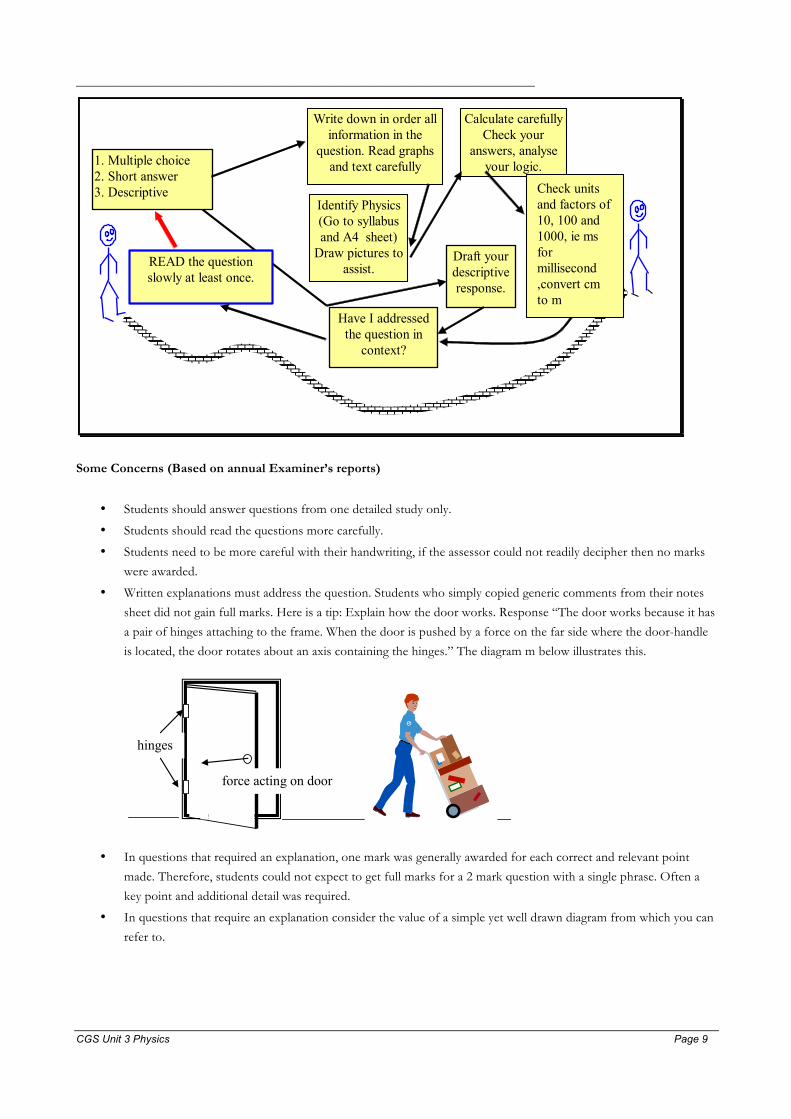
1. Multiple choice 2. Short answer 3. Descriptive
Write down in order all information in the
question. Read graphs and text carefully
Identify Physics (Go to syllabus and A4 sheet)
Draw pictures to assist.
Draft your descriptive response.
Calculate carefully Check your
answers, analyse your logic.
READ the question slowly at least once.
Have I addressed the question in
context?
Check units and factors of 10, 100 and 1000, ie ms for millisecond ,convert cm to m
Some Concerns (Based on annual Examiner’s reports)
• Students should answer questions from one detailed study only.
• Students should read the questions more carefully.
• Students need to be more careful with their handwriting, if the assessor could not readily decipher then no marks
were awarded.
• Written explanations must address the question. Students who simply copied generic comments from their notes
sheet did not gain full marks. Here is a tip: Explain how the door works. Response “The door works because it has
a pair of hinges attaching to the frame. When the door is pushed by a force on the far side where the door-handle
is located, the door rotates about an axis containing the hinges.” The diagram m below illustrates this.
force acting on door
hinges
• In questions that required an explanation, one mark was generally awarded for each correct and relevant point
made. Therefore, students could not expect to get full marks for a 2 mark question with a single phrase. Often a
key point and additional detail was required.
• In questions that require an explanation consider the value of a simple yet well drawn diagram from which you can
refer to.

CGS Unit 3 Physics Page 10 Page 10
• Students are still encouraged to show their working. Credit can be given for correct partial solutions to problems
or correct solution pathways but with incorrect numbers being used.
o write down data intended to use
o write down equation intended to use and transpose
o write down numbers substituted into equation
o write down result
• Unit conversions are still troublesome – km, mA, µF and the like.
• Students must follow the instructions given in the question. A number of questions specifically stated that working
must be shown. If this was not done no marks were awarded.
• Students still need to learn how to use their calculators accurately to perform standard operations: multiply, divide,
raising to a power, use of standard form.
• Students need to round off numbers only at the end of a calculation.
• Answers should be simplified to a decimal approximation to 2or 3 significant figures, not left as 310 or
10.6/240 and the like.
CGS Unit 3 Physics Page 11 Page 11
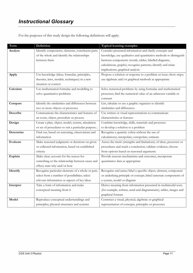
Instructional Glossary For the purposes of this study design the following definitions will apply.
Term Definition Typical learning examples
Analyse Identify components, elements, constituent parts
of the whole and identify the relationships
between them
Consider presented information and clarify concepts and
knowledge; use qualitative and quantitative methods to distinguish
between components (words, tables, labelled diagrams,
calculations, graphs); recognise patterns; identify and relate
implications; graphical analysis
Apply
Use knowledge (ideas, formulae, principles,
theories, laws, models, techniques) in a new
situation or context
Propose a solution or response to a problem or issue; show steps;
use algebraic and/or graphical methods as appropriate
Calculate
Use mathematical formulae and modelling to
solve quantitative problems
Solve numerical problems by using formulae and mathematical
processes; find the numerical value of an unknown variable or constant
Compare
Identify the similarities and differences between two or more objects or processes
List, tabulate or use a graphic organizer to identify similarities and differences
Describe
Communicate the characteristics and features of
an event, object, procedure or process
Use written or visual representations to communicate
characteristics or features
Design
Create a plan, object, model, system, simulation
or set of procedures to suit a particular purpose ;
Combine knowledge, skills, materials and processes
to develop a solution to a problem
Determine
Find out, based on reasoning, observations and
information
Recognise a quantity (often without the use of
calculations); interpolate; extrapolate; estimate
Evaluate
Make reasoned judgments or decisions on given
or collected information, based on established
criteria
Assess the merit (strengths and limitations) of ideas, processes or
procedures and reach a conclusion; validate evidence; choose
from options based on reasoned arguments
Explain
Make clear; account for the reason for
something or the relationship between cause and
effect; state why and/or how
Provide reasons mechanisms and outcomes, incorporate
quantitative data as appropriate
Identify
Recognise particular elements of a whole or part;
select from a number of possibilities; select
relevant information or aspects of key ideas
Recognise and name/label a specific object, element, component
or underlying principle or concept; label/annotate components of
a system, model or diagram
Interpret
Take a form of information and make
conceptual meaning from it
Derive meaning from information presented in multimodal texts
(for example, written, aural and diagrammatic), tables, images and
graphical formats
Model Reproduce conceptual understandings and
principles; physical structures and systems
Construct a visual, physical, algebraic or graphical
representation of concepts, principles or processes
CGS Unit 3 Physics Page 12 Page 12
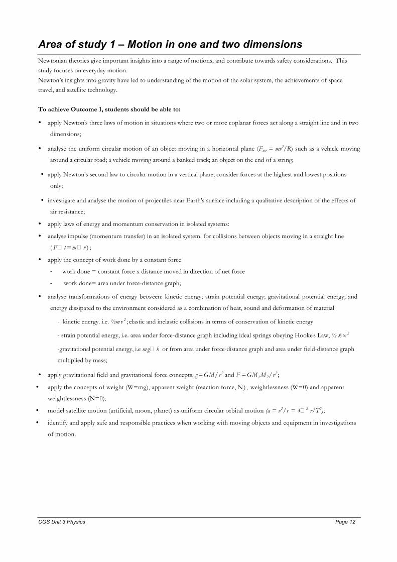
Area of study 1 – Motion in one and two dimensions Newtonian theories give important insights into a range of motions, and contribute towards safety considerations. This
study focuses on everyday motion.
Newton’s insights into gravity have led to understanding of the motion of the solar system, the achievements of space travel, and satellite technology.
To achieve Outcome 1, students should be able to:
• apply Newton's three laws of motion in situations where two or more coplanar forces act along a straight line and in two
dimensions;
• analyse the uniform circular motion of an object moving in a horizontal plane (Fnet = mv2/R) such as a vehicle moving
around a circular road; a vehicle moving around a banked track; an object on the end of a string;
• apply Newton's second law to circular motion in a vertical plane; consider forces at the highest and lowest positions
only;
• investigate and analyse the motion of projectiles near Earth's surface including a qualitative description of the effects of
air resistance;
• apply laws of energy and momentum conservation in isolated systems:
• analyse impulse (momentum transfer) in an isolated system. for collisions between objects moving in a straight line
( F � t = m � v ) ;
• apply the concept of work done by a constant force
- work done = constant force x distance moved in direction of net force
- work done= area under force-distance graph;
• analyse transformations of energy between: kinetic energy; strain potential energy; gravitational potential energy; and
energy dissipated to the environment considered as a combination of heat, sound and deformation of material
- kinetic energy. i.e. ½m v 2 ; elastic and inelastic collisions in terms of conservation of kinetic energy
- strain potential energy, i.e. area under force-distance graph including ideal springs obeying Hooke's Law, ½ k x 2
-gravitational potential energy, i.e m g� h or from area under force-distance graph and area under field-distance graph
multiplied by mass;
• apply gravitational field and gravitational force concepts, g = GM/r2 and F = GM1M2/r2 ;
• apply the concepts of weight (W=mg), apparent weight (reaction force, N) , weightlessness (W=0) and apparent
weightlessness (N=0);
• model satellite motion (artificial, moon, planet) as uniform circular orbital motion (a = v2/r = 4�2 r/T2);
• identify and apply safe and responsible practices when working with moving objects and equipment in investigations
of motion.
CGS Unit 3 Physics Page 13 Page 13
Area of study 2 – Electronics and Photonics Photonics is the science of using light to manipulate information and energy and involves all facets of visible, ultraviolet and
infrared radiation; for example, its production, detection, transport, storage and manipulation.
Photonics is the basis of much of modern communication technology. Photonic devices are used with electronic components in smoke detectors, burglar alarms, safety interlocks, televisions, cathode ray oscilloscopes, relative position
sensors, communication devices including fibre optic cables, modulators and demodulators, CD readers and writers, and
computer networks. Some phenomena which characterise the interface between electronics and photonics are introduced.
To achieve this outcome the student should be able to:
• apply the concepts of current, resistance, potential difference (voltage drop) and power to the operation of electronic
circuits comprising diodes, resistors, thermistors and photonic transducers including light dependent resistors (LDR),
photodiodes and light emitting diodes (LED), (V=IR, P=VI);
• calculate the effective resistance of circuits comprising parallel and series resistance and unloaded voltage dividers;
• describe energy transfers and transformations in opto-electronic devices;
• describe the transfer of information in analogue form (not including the technical aspects of modulation and
demodulation) using:
-light intensity modulation, i.e. changing the intensity of the carrier wave to replicate the amplitude variation of the
information signal so that the signal may propagate more efficiently
- de-modulation, i.e. the separation of the information signal from the carrier wave;
• design, investigate and analyse circuits for particular purposes using technical specifications related to potential
difference (voltage drop), current, resistance, power, temperature and illumination for electronic components such
as diodes, resistors, thermistors, light dependent resistors (LDR), photodiodes and fight emitting diodes (LED)
• analyse voltage characteristics of amplifiers including linear voltage gain (�Vout /�Vin) and clipping;
§ identify and apply safe and responsible practices when conducting investigations involving electrical. electronic and
photonic equipment.

CGS Unit 3 Physics Page 14 Page 14
Detailed study 3.2 – Structures and materials
The external force applied to a material can result in changes to the shape of the material. The type of force acting upon the
material, the shape of the material and how the material is used can influence the behaviour of a structure. The work done in changing the shape of a material can result in energy being stored in the material under strain (strain energy), or it can result
in the destruction of the material. This study looks at the behaviour of materials under load and how this behaviour will
affect such situations as the stability of a building or the strength of a bridge.
This study aims to develop students’ practical skills to enable them to better understand the structures of the natural world
and the restrictions of design in the technological world. Students will gain knowledge of the forces acting upon a material,
and learn to interpret the data resulting from the changes to the material. They will monitor the energy stored then released,
and be able to make comparisons of material properties. Investigations of the shape and composition of the material will be
carried out to determine its behaviour under stress up to the point of its destruction.
Students will use properties of structures and materials in the context of construction and design.
On completion of this unit the student should be able to analyse and explain the properties of construction materials, and
evaluate the effects of forces and loads on structures and materials. To achieve this outcome the student will draw on the
following key knowledge and apply the key
Key knowledge
To achieve this outcome the student should be able to:
• identify different types of external forces such as compression, tension and shear, that can act on a body, including
gravitational forces
• evaluate the suitability of different materials for use in structures, including beams, columns and arches, by comparing
tensile and compressive strength and stiffness or flexibility under load;
• analyse the behaviour of materials under load in terms of extension and compression, including Young’s modulus, E =
�/�
• calculate the stress and strain resulting from the application of compressive and tensile forces and loads to materials in
structures, � = F/A , � = ∆l/l
• describe brittle and ductile failure and apply data to predict brittle or ductile failure under load
• calculate the potential energy stored in a material under load (strain energy) using area under stress versus strain graph
• evaluate the toughness of a material tested to the point of failure
• describe elastic or plastic behaviour of materials under load and the resulting energy transformed to heat
• evaluate the suitability of a composite material for its use in a structure by considering its properties and the properties of the component materials (maximum of three components)
• calculate torque, � = r ⊥ F
• analyse translational and rotational forces (torques) in simple structures, including uniform columns, struts, ties, beams,
cables, but not including trusses, modelled as two-dimensional structures in static equilibrium
• identify and apply safe and responsible practices when working with structures, materials and associated measuring
equipment in investigations of materials.

CGS Unit 3 Physics Page 15 Page 15
Summary: MOTION IN ONE AND TWO DIMENSIONS
Motion is a fundamental part of Physics. Everything moves through space and time and an appreciation of why various
motions occur allows us to understand, predict and control moving things. The Newtonian model rests on the assumption
that objects can be described as points in space and time and that space and time are absolute in the sense that the values of
length and time interval measurements are the same for all observers. The first assumption breaks down at the atomic level,
where Quantum Mechanics is more successful and the second assumption breaks down for fast moving objects where
Special Relativity is more correct and successful.
Basic Definitions
• Displacement s or �x is the measure of the shortest distance between two points.
• Distance is the length of the path taken during a specified motion. [don’t be afraid to use Pythagoras’ theorem if
you have to]
• Displacement is a directed quantity and hence a vector whereas distance is a scaler. You can walk for miles in a circle
and get no where.
• Speed is the distance travelled divided by the time taken whereas velocity is the displacement divided by the time taken.
• When motion is restricted to a straight line in a fixed direction then the magnitude of average velocity is the same
as the average speed.
• Average speed = takentime travelleddistance
whereas average velocity = txΔ
Δ
• Speed and velocity have different definitions. Velocity is a vector and speed is a scaler. Both velocity and speed
have the unit m s-1 however.
• A common unit for speed is km h-1. To convert from km h-1 to m s-1 divide by 3.6 km h-1 per m s-1. Thus
100 km h-1 is equal to 27.8 m s-1.
• Acceleration is the time rate of change of velocity and has the unit m s-2: tvaΔ
Δ= . Acceleration is how fast you
change velocity, that is the rate at which you change velocity.
Graphical descriptions of motion: displacement, velocity, acceleration time graphs
Along with the equations of motion, are graphical descriptions of motion. These involve
1) displacement vs time, 2) velocity vs. time and 3) acceleration vs time graphs.
Δt
x (m)
t (s)
Δx
T
B
A
displacement vs time
txvav Δ
Δ= = gradient of line segment AB
(average velocity during the time interval �t)
The gradient at time T gives the instantaneous velocity at
time T
CGS Unit 3 Physics Page 16 Page 16
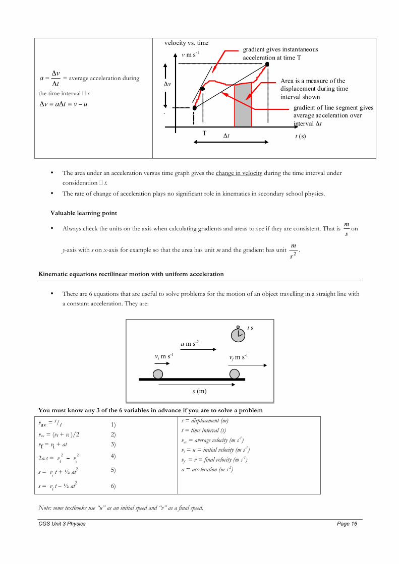
tvaΔ
Δ= = average acceleration during
the time interval �t
uvtav −=Δ=Δ
velocity vs. time
Δt
v m s-1
t (s)
Δv
T
Area is a measure of the displacement during time interval shown
gradient gives instantaneous acceleration at time T
gradient of line segment gives average acceleration over interval Δt
• The area under an acceleration versus time graph gives the change in velocity during the time interval under
consideration �t.
• The rate of change of acceleration plays no significant role in kinematics in secondary school physics.
Valuable learning point
• Always check the units on the axis when calculating gradients and areas to see if they are consistent. That is sm
on
y-axis with s on x-axis for example so that the area has unit m and the gradient has unit 2sm
.
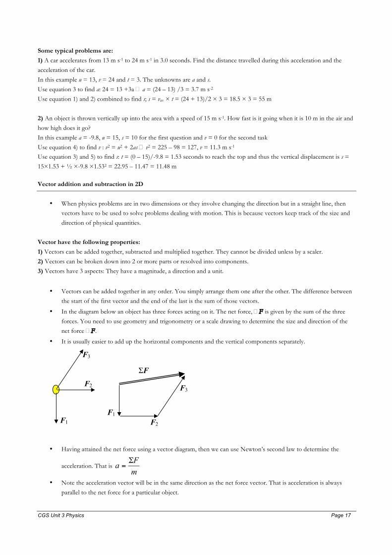
Kinematic equations rectilinear motion with uniform acceleration
• There are 6 equations that are useful to solve problems for the motion of an object travelling in a straight line with a constant acceleration. They are:
s (m)
vi m s-1 vf m s-1
a m s-2
t s
You must know any 3 of the 6 variables in advance if you are to solve a problem
vav = s/t 1)
vav = (vf + vi )/2 2)
vf = vi + at 3)
2a.s = vf
2 − vi
2 4)
s = vi t + ½ at2 5)
s = vf t − ½ at2 6)
s = displacement (m)
t = time interval (s)
vav = average velocity (m s-1)
vi = u = initial velocity (m s-1)
vf = v = final velocity (m s-1)
a = acceleration (m s-2)
Note: some textbooks use “u” as an initial speed and “v” as a final speed.
CGS Unit 3 Physics Page 17 Page 17
Some typical problems are:
1) A car accelerates from 13 m s-1 to 24 m s-1 in 3.0 seconds. Find the distance travelled during this acceleration and the
acceleration of the car.
In this example u = 13, v = 24 and t = 3. The unknowns are a and s.
Use equation 3 to find a: 24 = 13 +3a � a = (24 – 13) /3 = 3.7 m s-2
Use equation 1) and 2) combined to find s; s = vav × t = (24 + 13)/2 × 3 = 18.5 × 3 = 55 m
2) An object is thrown vertically up into the area with a speed of 15 m s-1. How fast is it going when it is 10 m in the air and
how high does it go?
In this example a = -9.8, u = 15, s = 10 for the first question and v = 0 for the second task
Use equation 4) to find v : v2 = u2 + 2as � v2 = 225 – 98 = 127, v = 11.3 m s-1 Use equation 3) and 5) to find s: t = (0 – 15)/-9.8 = 1.53 seconds to reach the top and thus the vertical displacement is s =
15×1.53 + ½ ×-9.8 ×1.532 = 22.95 – 11.47 = 11.48 m
Vector addition and subtraction in 2D
• When physics problems are in two dimensions or they involve changing the direction but in a straight line, then vectors have to be used to solve problems dealing with motion. This is because vectors keep track of the size and
direction of physical quantities.
Vector have the following properties:
1) Vectors can be added together, subtracted and multiplied together. They cannot be divided unless by a scaler.
2) Vectors can be broken down into 2 or more parts or resolved into components.
3) Vectors have 3 aspects: They have a magnitude, a direction and a unit.
• Vectors can be added together in any order. You simply arrange them one after the other. The difference between
the start of the first vector and the end of the last is the sum of those vectors.
• In the diagram below an object has three forces acting on it. The net force, �F is given by the sum of the three
forces. You need to use geometry and trigonometry or a scale drawing to determine the size and direction of the
net force �F .
• It is usually easier to add up the horizontal components and the vertical components separately.
ΣF
F1
F2
F3
F1
F3
F2
• Having attained the net force using a vector diagram, then we can use Newton’s second law to determine the
acceleration. That is mFa Σ
=
• Note the acceleration vector will be in the same direction as the net force vector. That is acceleration is always
parallel to the net force for a particular object.

CGS Unit 3 Physics Page 18 Page 18
• Vector subtraction is a little more difficult, but it is important to understand, particularly so that acceleration can be
found from final and initial velocity vectors.
The trick is to realise that:
i f A = B + C then C = B – A= B + ( -A)
The ve c tor –A is jus t the ve c tor A but po in t ing in the oppos i t e d i r e c t ion to the ve c tor A.
Vector subtrac t ion a l lows you to ca l cu la t e the d i f f e r ence be tween two ve c tor s and i s shown be low.
B
A B
-A B - A
Again you use triangle rules here to determine the size and direction of B – A. It is initially difficult to interpret what B –
A means but in the case of the change in velocity �v = v final – v init ia l measures the difference in both the size and direction
of the two velocity vectors and allows for the acceleration vector to be found since tvaΔ
Δ= as a vector equation.
In Year 12 a key skill is to:
1) identify and add together forces to find the net force and
2) identify and subtract either velocity or momentum to find the change in those quantities.
3) add and subtract relative velocity to find the velocity of object in a second reference frame when the velocity of
the object is known in another reference frame.
Below are some examples of vector addition and subtraction.
1) Addition: A falling ball of mass 3 kg has an air drag of 12 N. What is the net force.
29.4 N
12 N
Add the two vectors to get 29.4 down + 12 up =17.4 N down
2) Subtraction: a tennis ball strikes a wall with velocity 15 m s-1 west and rebounds with velocity 13 m s-1 east. What is the
change in velocity?
�v = vfinal – vinitial = 13 m s-1 east – 15 m s-1 west = 13 m s-1 east + 15 m s-1 east
= 28 m s-1 east
3) A car turns a corner at an intersection. Initially it is going 8.0 m s-1 south and afterwards is going 5.0 m s-1 east. What is
the change in velocity?
�v = vfinal – vinitial = 5 m s-1 east – 8 m s-1 south = 5 m s-1 east + 8 m s-1 north

CGS Unit 3 Physics Page 19 Page 19
= 4.989 = m s-1 at an angle of tan-1(8/5) = 58° North from east; E 58 N or 32 True.
Force components in 2 dimensions
• Any vector, such as a force can be decomposed into 2 or more components. It is useful to break forces into
two vectors that are perpendicular to each other.
• Consider an aircraft taking off. The combined force due to the engines is given by the vector force F . This
force can be decomposed into a horizontal component F x and a vertical component F y.
• The magnitude of each of these forces are
Fx = F×cosθ and Fy = F×sinθ.
The magnitudes of the three vectors are related by Pythagoras’s Theorem
so that F2 = Fx2 + Fy2.
F Fy = Fsinθ
Fx = Fcosθ
up
θ
aircraft
across
• The vertical component of the force, F y acts against the weight of the aircraft allowing it to increase in altitude
while the horizontal component, Fx pushes the aircraft horizontally.
• As an interesting sideline, the motion of the wings through the air is the cause of why the wings provide an
upthrust and consequently support the plane against the force of gravity.
• A second example of where decomposing vectors arises in projectile motion when the launch velocity of a golf
ball [for example] is decomposed into its vertical and horizontal components. Thus a golf ball leaves the tee at a
speed of 80 m s-1 at an angle of elevation of 10° will have a vertical velocity component or vertical speed of 80
sin 10° = 13.9 m s-1 and a horizontal velocity component or horizontal speed of 80 cos 10° = 78.8 m s-1.

CGS Unit 3 Physics Page 20 Page 20
Forces in 2D; friction, normal reaction, non-contact forces
Gravity
The force due to gravity acting on an object is called the weight W of an object.
mgW = where g is the gravitational field strength [ g = 9.81 N kg-1 near the surface of the earth] and m is the mass (kg) of
the object. A 60 kg person has a weight of W = 60×9.81= 588 N down. Remember weight is a vector, it is a force while
mass is a scaler. The weight of an object depends on the strength of the gravitational field it is placed in whereas the mass of
an object is an intrinsic property of the object. The gravitational field strength at the surface of the moon is about 1.6 N kg-1
about 1/6 that of the surface of the earth.
“Contact forces”
When a cup rests on a table there is an upward contact force acting on it. The normal contact force N is an electrical force
of repulsion that pushes up on the cup or object that is resting on a surface. It is not the reaction force of the weight of the
block that is discussed in Newton’s third law. The normal contact force comes about because the force of gravity acting on
the object pulls it downward but the surface such as a table or ground is in the way. The electrons of the surface repel the
electrons of the object, thus the normal contact force is upwards. Only when the object is not accelerating (�F = 0)
vertically does the size of N equal the size of mg in compliance with Newton’s first law.
Friction is the tangential contact force and is also electrical in origin that arises when two solid objects move relative to each
other or attempt to move relative to each other when in contact.
Air drag is a force associated with the movement of an object through a fluid such as water of air.
Applied forces are those applied to the object such as a push or a pull. You push a shopping trolley or you pull on a rope.
Tension is a word used to describe the force that a taut rope, string or cable acts on an object. Note that the object will
exert a force on the rope to make the rope taut.
All forces regardless of type can be represented by vectors.
All forces come in pairs: this is described Newton’s third law. We write all forces using the notation Fobject A acting on object B. For
example the weight of a car W can be written as F earth acting on car
Force diagrams for bodies
To understand the motion of objects it is necessary to understand the forces that act on the object. Vector diagrams
illustrating the forces that act on objects allow the subsequent motion to be understood and predicted. On the next page are
6 common situations encountered in physics problem-solving.

CGS Unit 3 Physics Page 21 Page 21
a stationary person constant velocity accelerating
ball rolling downa slope
cricket ballthrough theair
constantvelocity
velocity
a) b) c)
d) e) f)
a) b) c)
d) e) f)
N
W
N
W
AT
N
W
AT
W
D
W
NF
D
W
In the diagram below an object is being pulled across a table with an applied force. The other three forces are the force of
gravity, normal contact force and the force of sliding friction.
Normal contact force
Weight
Applied force Friction
N
W
A F
The net force horizontally �Fh = A + F which g ive s r i s e to A – F as a number
The net force vertically �Fv = N + W which g iv e s r i s e to N – W as a number
The vast majority of dynamics problems in Year 12 are applications of this model of opposing forces acting on an object.
The outcome is either equilibrium where opposing forces sum to zero, in which case the body will have a constant velocity
(zero acceleration) as is the case vertically or the outcome is not equilibrium where the net force is not zero in which case
the body will accelerate as is the case horizontally in the direction of the net force.
CGS Unit 3 Physics Page 22 Page 22
Newton I, II and III laws of motion
Newton I: When a body travels at a constant velocity the net force acting on it is zero newton. When the net force acting
on a body is zero newton then a body will travel with a constant velocity.
Note that constant velocity means zero acceleration. Also a constant velocity also refers to an object that is stationary; it
has a constant velocity of 0.
Newton II: mF
a ∑= . A body will have an acceleration a proportional to the net force and inversely proportional to the
mass of the body.
NOTE: you only add forces that act on a single body together. You do not add forces together that act on different bodies.
The net force acting on a car is the sum of the forces acting on the car. Any forces that the car may exert on the road or a
tree do not determine the motion of the car. They will determine the motion of the road or the tree however. Remember to
find the net force acting on a body only add up forces that act on that body.
The unit of force is a derived unit. 1 newton is the force required, by definition to cause an acceleration of 1 m s-2 on a 1 kg
mass.
Newton III: Forces are produced in pairs. For example the gravitational force that the earth exerts on an apple has a pair. It
is the gravitational force that the apple exerts on the earth. We use this notation to specify the law:
1221 ⇒
→
⇒
→
−= FF
The force that one body exerts on another body is the same size as the force that the second body exerts back onto the first body. But the two forces are in opposite directions and they act on different object.
NOTE: you would not add these forces together because they act on two different objects.
Do not confuse the third law with the first two laws. The first two laws state what happens to a single body acted on by
a number of forces or by no force at all. The third law states what happens when two bodies interact.
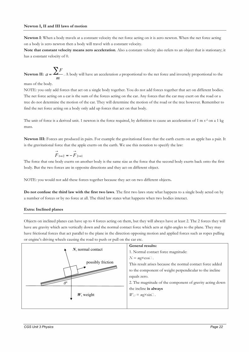
Extra: Inclined planes
Objects on inclined planes can have up to 4 forces acting on them, but they will always have at least 2. The 2 forces they will
have are gravity which acts vertically down and the normal contact force which acts at right-angles to the plane. They may
have frictional forces that act parallel to the plane in the direction opposing motion and applied forces such as ropes pulling
or engine’s driving wheels causing the road to push or pull on the car etc.
N, normal contact
W, weight
possibly friction
θ°
General results:
1. Normal contact force magnitude:
N = mg×cos�.
This result arises because the normal contact force added
to the component of weight perpendicular to the incline
equals zero.
2. The magnitude of the component of gravity acting down
the incline is always
W// = mg×sin�.

CGS Unit 3 Physics Page 23 Page 23
Kinematics and dynamics of projectile motion in a uniform gravitational field
In projectile motion, an object is released at a speed v with an angle of elevation θ.
The acceleration of the object is 9.8 m s-2 down at all times [modelled as motion without regard to air-resistance] and the net
force acting on the projectile at all times is the weight of the object.
v
θ
g apex
range
g
vg
vgv
gvt
tvsvva
gttvsgtvvga
fx
fy
θθ
θ
θ
θθ
θθ
2sin range ,2sin height max
sin2 flight of time
,sin timeaat occursheight max
cos cos 0 :lyhorizontal21sin sin :vertically
222
2
==
=
=
===
−=−=−=
Important points to remember.
At the top of the flight the projectile has a speed = vcos� and a constant acceleration of 9.8 m s-2 down.
In the absence of air resistance the net force acting on the projectile is always and only the weight of the object. This net
force is vertically downward at all times.
Qualitative discussion of the effects of air resistance for projectiles
• Drag is a frictional force arising when a solid object moves through a fluid such as water or air. The direction of
the force of air resistance or drag is opposite to the direction of motion of the object.
• When a body is projected vertically up the drag force acts along with gravity to produce an upward deceleration
greater in magnitude than the deceleration due to gravity alone. After coming to rest the object will fall and the
drag force will now oppose the weight giving rise to a downward acceleration less than 9.8 m s-2.
• When a body is projected vertically up it will reach its maximum height in a time smaller than that if there were no
air-resistance. It will take a longer time to reach the ground that would be the case if there were no air resistance.
In projectile motion the time of flight is less and the range is less than would be the case in the absence of air
resistance.
Kinematics and dynamics of uniform circular motion in horizontal planes and at the top or bottom of circular
motion in a vertical plane
An object is said to be executing Uniform Circular Motion [UCM] when it is travelling in a circle with a constant speed.
Because the velocity vector is constantly changing direction however, the object has a non-zero acceleration and thus a non-
zero net force must act on it in compliance with Newton’s second law of motion since ∑F = ma.
This acceleration is directed towards the centre of the circle and thus the net force is also directed towards the centre of the
circle. Newton’s second law implies that the vector �F and acceleration a are parallel.
The following kinematic results are useful in solving problems.

CGS Unit 3 Physics Page 24 Page 24
a
v
O r
1) speed of object moving at a tangent to circle = rfTrv ππ 22
==
2) acceleration of object towards the centre = rv
Tr
rva
2
2
242===
ππ,
where r is the radius of the circle, T is the period of orbit, f is the frequency, v is the orbital speed and a is the acceleration
towards the centre.
To evaluate the force required to keep an object in uniform circular motion, use Newton’s second law to obtain:
3) 2
22 4Trm
rmvF π
==
Vertical Circular Motion
As an application of circular motion, cars travelling over roads that are the arcs of circles, or cars performing loop-to-loops
in stunts are examined. You need to be aware of what is happening at the bottom or top of such a motion which may be
modelled using circular motion.
Before we start these applications, always remember to make forces directed towards the centre as positive numbers and forces directed away from the centre as negative numbers when doing calculation. This convention is worth adopting to
avoid confusion.
1. Car on a bridge:
mg > N because the net force acting is rmv 2
. Because N < mg a person experiences a normal contact force less than the
size of their weight. They feel as though they weigh less than usual.
mg
Nmgr
mvF −==∑2
v
N towards centre
away from centre

CGS Unit 3 Physics Page 25 Page 25
A person will feel weightless when N = 0 in which case grvgrvmgrmv
=⇒=⇒= 22
for this to occur. Occupants
inside an airplane travelling in the arc of a circle with a speed v = r8.9 will appear weightless when viewed from within
that frame of reference. The film sequences in “Apollo 13” with Tom Hanks were achieved this way.
2. Car at the bottom of a trough:
Because the net force acting is rmv 2
it follows that mg < N. Thus N > mg a person experiences a normal contact force of
the seat of the car acting on them that is more than the size of their weight. They feel as though they weigh more than
usual.
N
mg
mgNr
mvF −==∑2
v towards centre away from
centre
This distinction between actual weight (mg) and the sensation of weight (N) is discussed in the gravity section of the course.
Usually our sensation of weight is determined by the normal contact force acting on us N and our actual weight mg have the
same value since we perform that measurement in a situation where the acceleration a = 0 for the participant.
3. Circular motion of a car on a banked track
Circular motion can take place on a banked track with banking angle �°. The banking of the track assists in keeping the car
in a circular path by utilising the horizontal component of the normal contact force by the road on the car. In the situation
where static friction by the road on the car (parallel to the banked road) = 0 then a simple analysis of circular motion can be
made. The diagram below, showing a car from the rear travelling in a horizontal circle with centre C to the left of the car
gives a force vector diagram.
C r
N car
mg θ°
With friction = 0 (a model assumption), Ncos� = mg [Eq 1](since vertically the acceleration, and hence net vertical force
on the car =0). Horizontally, Nsin� = rmv 2
[Eq 2]since it is the horizontal component of N in the absence of road
friction that provides the force necessary for the car to move in a circular path.

CGS Unit 3 Physics Page 26 Page 26
An intereting result can be found by dividing Eq 2 by Eq 1 to give tan�° = grv 2
. Solving this for � gives the optimum
banking angle for a corner for a given speed. This optimum is achieved precisely when static friction by the road on the car
is zero allowing the horizontal component of the normal contact force to supply all the force necessary for the car to move
in a circle. If the speed were greater, static friction would act down the incline as the car would attempt to slide out or up the
incline. If the speed were slower there would be a tendency for the car to slide down the incline resulting in a static friction
force up the incline.
4. Circular motion of an object on the end of a string
An object on the end of a string twirled around in a horizontal circle is also an example of circular motion. In this case there
are two forces acting on the object, the tension due to the string acting on the object and the weight of the object. The
diagram below shows this.
The horizontal component of the string tension provides the force required to keep the object in circular motion. The
vertical component of the tension balances the weight of the object.
a
v
O r
mg
θ
T
In this case Tcos� = mg (since vertically the acceleration, and hence net vertical force on the object=0) and Tsin� = rmv 2
.
Consequently the angle that the string makes to the horizontal depends on the speed of the object and the radius of the
circular path: tan� = grv 2
.
Mathematically the object on the string in a horizontal circular motion scenario is mathematically very similar to the car in a
circular path on a banked road. This is because the tension force in the string plays the same role as the normal contact
force by the road on the car.
CGS Unit 3 Physics Page 27 Page 27
Momentum, impulse and Newton’s second law
“impulse i s the amount o f g runt that a for c e has”
Grunt g iv e s r i s e to a change in momentum
1) Momentum, p , is defined as p = mv kg m s-1. It is a vector quantity.
The momentum of an 80 kg athlete running North at 5.0 m s-1 is 4.0 × 10² kg m s-1 North.
Note the full specification of momentum as a vector is size, unit and direction.
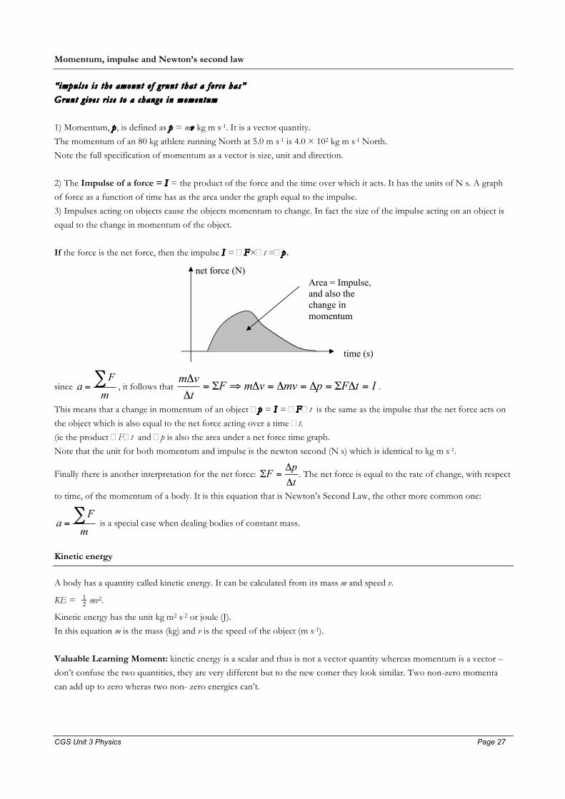
2) The Impulse of a force = I = the product of the force and the time over which it acts. It has the units of N s. A graph
of force as a function of time has as the area under the graph equal to the impulse.
3) Impulses acting on objects cause the objects momentum to change. In fact the size of the impulse acting on an object is
equal to the change in momentum of the object.
If the force is the net force, then the impulse I = �F�t =�p .
net force (N)
time (s)
Area = Impulse, and also the change in momentum
since mF
a ∑= , it follows that ItFpmvvmF
tvm
=ΔΣ=Δ=Δ=Δ⇒Σ=Δ
Δ.
This means that a change in momentum of an object �p = I = �F�t is the same as the impulse that the net force acts on
the object which is also equal to the net force acting over a time �t.
(ie the product �F�t and �p is also the area under a net force time graph.
Note that the unit for both momentum and impulse is the newton second (N s) which is identical to kg m s-1.
Finally there is another interpretation for the net force: tpFΔ
Δ=Σ . The net force is equal to the rate of change, with respect
to time, of the momentum of a body. It is this equation that is Newton’s Second Law, the other more common one:
mF
a ∑= is a special case when dealing bodies of constant mass.
Kinetic energy
A body has a quantity called kinetic energy. It can be calculated from its mass m and speed v.
KE = 21 mv2.
Kinetic energy has the unit kg m2 s-2 or joule (J).
In this equation m is the mass (kg) and v is the speed of the object (m s-1).
Valuable Learning Moment: kinetic energy is a scalar and thus is not a vector quantity whereas momentum is a vector –
don’t confuse the two quantities, they are very different but to the new comer they look similar. Two non-zero momenta
can add up to zero wheras two non- zero energies can’t.

CGS Unit 3 Physics Page 28 Page 28
Definition of work W done by a force
“Work is the amount of “oomph” that a force has”
Oomph gives rise to a change in kinetic energy
Work done by a force is given the symbol W and is the product of the force component in the direction of the displacement
and the displacement over which the force component acts. F
x
θ
W = F×x×cosθ
Work has the unit N m or the newton metre. This unit is called the joule or J.
For example: a 15 N horizontal force acts on a trolley over a horizontal distance of 0.50 m then the work done by that force
is 15 × 0.50 = 7.5 J.
When a force F acts on an object while it displaces x then work is said to have been done by that force.
A force acting on a stationary object does no work because the displacement is zero.
A force acting at right angles to the displacement of an object also does zero work [cos 90° = 0]. An excellent example of
this is uniform circular motion. The centre-directed force is always 90° to the displacement and hence no work is done by
that force – the force constantly changes the direction of the objects velocity, but not the size of the velocity.
Energy transfers as area of force displacement graph
When forces act on objects and the objects move a distance, the force acting can be plotted against the distance moved. The
area under the graph is the work done by that force. This is because the area under the graph is in fact the product of F and
�x.
If the force is the net force then the area under the graph will be equal to the change in kinetic energy of the object or if the
object is fixed and stretches or is compressed the area is equal to the stored strain energy in the material. But more about
that later. As a general concept the work done by the net force will change the amount of energy that the object has.
Force (N)
distance (m)
Area = work done by force, and also the change in kinetic energy if force is the net force
Work-energy theorem
Work done by the net force equals the change in kinetic energy.
W = ΔKE = 1/2 mvf 2 - 1/2 mvi 2
This tells us that when a net force �F acts on an object while it displaces an object then a change in kinetic energy results in
that object.
For example if a car experiences a net force of 300 N over a distance of 20 m in the direction that it is travelling then the
work done by that net force is 6000 J and this is equal to the increase in kinetic energy of the car.

CGS Unit 3 Physics Page 29 Page 29
Simple collisions in one dimension
• When simple collisions are modelled in one dimension, the key quantities to calculate are the momenta of each
object before and after the collision and the kinetic energy of each object before and after the collision as well as
the total momentum and total kinetic energy.
• If the total momentum before, during and after the collision is a constant then the collision is said to be an
isolated collision. What this means is that the net external force acting on the objects is negligible and so only the
forces acting between the objects are considered. Newton’s third law tells us that these forces are equal and
opposite in direction.
• Consequently in an isolated collision the momentum lost by one object is equal to the momentum gained by the
other object. [remember that momentum is a vector quantity]
• If the kinetic energy before and after the collision is constant, then the collision is said to be an elastic collision.
During the collision energy may be temporarily stored in the objects as elastic potential energy. Elastic collisions
are therefore ones where all the potential energy stored during the collision is retrieved as kinetic energy after the
collision has occurred. In elastic collisions the total mechanical energy is a constant at all times.
• Inelastic collisions therefore are ones where not all the stored energy is retrieved as kinetic energy. The most common transformation is 1) that thermal energy or heat is produced or 2) in which the colliding objects suffer
permanent deformations or structural damage or 3) where sound is radiated away from the site of the collision.
Generally collisions are ineleastic.
Conservation of momentum in 1D
In an isolated collision, the momentum before the collision equals the total momentum after the collision.
That is the momentum lost by one object is equal to the momentum gained by the second object. This comes about because
of Newton’s third law which shows that the impulse of Object A on Object B is equal to minus the impulse of Object B on
Object A during a collision. Impulse is of course also equal to the change in momentum.
timesallat constant 0)(
0
=+
=+Δ
=Δ+Δ
Δ−=Δ
BA
BA
BA
BA
pppppppp
Elastic and inelastic collisions in 1D
The sticky collision
As examples of collisions we study the sticky collision. In this collision, the two objects collide and have the same velocity
after the collision as they are stuck together. The speed of approach is equal to v and the speed of separation is 0, but the
two objects move to the right with a speed V after the collision.
M m (M+m)
v V Before After
The momentum before and after the collision are equal because the collision is an isolated one by definition.

CGS Unit 3 Physics Page 30 Page 30
vmM
MVVmMMv ×+
=⇒+= )( . It is easy to show that if a sticky collision is isolated then it is not possible for it
to be an elastic one.
As an exercise, show that the expression for the kinetic energy before the collision is greater than the expression for the
kinetic energy after the collision. If successful you will have shown that mM
MKEKE
before
after
+= . This result tells you that a
sticky collision cannot be an elastic one since the fraction M/(M + m) must always be strictly less than 1
The elastic collision
An elastic collision is where no energy is converted to heat or permanent deformation of the colliding objects, both
momentum conservation and kinetic energy conservation must be conserved simultaneously. Therefore to decide whether a
collision is elastic or otherwise you need to check both the total momentum and total kinetic energy of the participants
before and after the collision.
For an elastic collision the following result occurs:
VA m s-1 stationary
Before the collision
VA’ m s-1
After the collision
VB’ m s-1
Car A mass=mA
Car A Car B mass = mB
Car B
The result, after much tedious algebra is
Aba
aB v
mmmv ×+
=2' while A
BA
BAA v
mmmmv ×
+
−=' .
It is useful to obtain predictions for when mA = mB and for when the masses are mA > mB and
mA < mB. You get a good feel for what happens in an elastic collision. It may also improve your billiards.
A useful result for a collision that is elastic:
the speed of approach = the speed of separation. That is if Car A approaches Car B at 10 m s-1(for example) and Car B moves away from Car
A at 10 m s-1 then the collision is elastic
Gravitational Potential energy
Close to the surface of the earth, the change in gravitational potential energy ΔPEg is given by
ΔPEg = mgΔh
where Δh is the increase in the height of the mass m in a field of strength g. For example, if you climb 3.0 m up the steps to a
first floor and your mass is 80 kg then the increase in the gravitational potential energy is 80×9.8×3.0 = 2.35×10³ J.
Mechanical energy as equal to the sum of Kinetic and Potential energy
ME = PE + KE
ME = mgh + 2
21mv = constant for a projectile where the projectile has both kinetic and potential energy. The path of a
projectile where air resistance is ignored is governed by the energy equation above. And hence:
ME1 = mgh1 + 212
1mv = mgh2 + 222
1mv = ME2. This is useful for doing problems involving “big dipper” type rides.

CGS Unit 3 Physics Page 31 Page 31
Hooke’s Law and the stretchable object
Hooke’s Law is a model for the behaviour of an object under small applied forces. All objects which are subject to external
forces will change there shape.
When an elastic material is stretched or compressed the change in shape x is proportional to the size of the applied force F.
F = kx.
The constant k gives the stiffness of the material. When k is small the material changes shape readily, if k is big the material
is rigid. Rubber bands have k values in the range 5 – 100 N m-1 whereas a piece of metal wire may have a k value or order
106 N m-1.
F (N)
Hooke’s Law F = kx
x (m)
gradient is equal to the stiffness k with unit N m-1
area gives the energy stored in the stretched or compressed medium. The unit is joule
area = 2
21kx
Spring constant k with units of N m-1
The stiffness of a spring or elastic material is called the spring constant it is found graphically by measuring the gradient of a
force – displacement curve assuming the curve to be a linear function.
Elastic Potential Energy
The energy stored in a stretched material is called the elastic potential energy or strain energy and is calculated graphically as
the area under a force – displacement curve for the material. For a curve obeying Hooke’s law, F = kx, the energy can be
calculated algebraically using the formula for the area of the triangle formed below the straight line.
PEel = 1/2 kx2joule.
Conservation of mechanical energy and conservative systems; simple applications
• The notion that energy is neither created nor destroyed is a powerful idea that permeates all science. For example the
dropping of a ball can be viewed as a loss of gravitational potential energy and a gain in kinetic energy of the ball. The
amount of potential energy lost by the ball equals the amount of kinetic energy gained by the ball provided we can
ignore the work done by air-drag. The total mechanical energy of a system or an object is simply the sum of kinetic
energy and potential energy.
• If frictional forces are ignored, as they ultimately produce heat, a form of energy that conducts, convects and radiates
away from a mechanical system then many systems can be treated as though the total mechanical energy is a constant.
In this case, work done by forces simply convert energy from one type to another. This is a second way of looking at
the effects of work: it is the total amount of energy converted from one type to another type.
Mechanical energy loss in collisions due to converting stored energy into heat
• In the following graph, energy is stored temporarily by stretching or compressing a material.

CGS Unit 3 Physics Page 32 Page 32
• For example the bumper bar of a car may be compressed as it hits a second car. Let’s consider this at a slow speed so
that little observable damage is made during the collision. As the car’s bumper bar compresses �x, the force exerted on
the bumper bar by the second car increases. A plot of this force vs compression variation will look a little like a
Hooke’s-law graph. The graph will reach a maximum compression at the midpoint of the collision and then the bumper
bar will decompress as the second half of the collision begins to occur. Collisions may be thought of as having a loading
[O to A] and unloading phase [A to B]. The graph will return from A to B when the collision is over. If there is no
damage, B will be the origin. If there is damage, there will be a permanent �x and the point B will lie on the x axis.
• Either way the area under the graph on the first half of the collision [loading phase] is greater than the area under the
graph on the return [unloading phase]. This type of graph is typical of a graph of an inelastic collision where energy is
temporarily stored and some of it is released. The area between the two graphs is the energy transformed into heat and
sound or resulting in a permanent change in shape of the bumper bar or impact vehicle.
A
Δxmax
F2nd car on bumper bar
Δx B O
A
Δxmax
F2nd car on bumper bar
Δx B O

CGS Unit 3 Physics Page 33 Page 33
Newton’s law of gravity
Newton proposed that two massive bodies attract each other with a force that is proportional to each of the masses of the
bodies and inversely proportional to the square of the distance between their centres. It is precisely this type of force that
can account for the elliptical orbits of planets about the sun and moons about the planets and account for gravitational
forces in general. No a bad effort to explain the motion of planets and apples all in the one formula.
2rGMmF =
The constant G = 6.67 × 10⁻¹¹ N m2 kg-2 and is called the Universal Gravitational Constant.
• In the above formula, M is the mass of the large object, m is the mass of the small object and r is the distance between
the centres of the two masses.
• The value of G gives the gravitational force acting on a 1 kg mass by a second 1 kg mass when they are separated by 1
m. This force is exceedingly small: 6.67 × 10⁻¹¹ N to be exact, but when large objects such as the earth are involved the
gravitational force acting on an apple can have a moderate effect. Newton’s law of gravity simultaneously explains the
motion of planets about the Sun, the moon about the earth and the falling of an apple.
• There are a couple of things to consider and understand.
• Newton’s third law applies here and hence while the apple is attracted to the earth, the earth is also attracted to the
apple with the same sized force.
• From our perspective on earth it appears that the moon orbits the earth. If you were on the moon however you would be quite right is saying that the earth orbits the moon. Recall the famous photograph of “earthrise” taken by American
astronauts.
Fearth on moon
Fmoon on earth
Fyou on me
Fme on you
Me You
Table 1 shows data for the Sun and the four innermost of its planets and the moon.
Object Mass (kg) Radius (m) Period of
rotation (s)
Radius of
orbit (m)
Period of
revolution (s)
Sun 1.98 x 1030 6.95 x 10⁸ 2.14 x 10⁶
Mercury 3.28 x 10²³ 2.57 x 10⁶ 5.05 x 10⁶ 5.79 x 10¹⁰ 7.60 x 10⁶
Venus 4.83 x 1024 6.31 x 10⁶ 2.10 x 10⁷ 1.08 x 10¹¹ 1.94 x 10⁷
Earth 5.98 x 1024 6.38 x 10⁶ 8.61 x 10⁴ 1.49 x 10¹¹ 3.16 x 10⁷
The moon 7.35 × 10²² 1.74 × 10⁶ - 3.30 × 10⁸ 2.36 × 10⁶
Mars 6.37 x 10²³ 3.43 x 10⁶ 8.85 x 10⁴ 2.28 x 10¹¹ 5.94 x 10⁷
Valuable learning moment:
We often talk about the altitude of a satellite above the surface of the earth. This distance is not the distance to use in
Newton’s law of gravity, which is the separation from the centres of both objects.
The radius of the earth is 6.38 × 10⁶ m and so if altitudes are quoted the radius of the earth must be added in. Note also an
altitude of 400 km = 4.00 × 10⁵ m or 0.400 × 10⁶ m.

CGS Unit 3 Physics Page 34 Page 34
Kinematic properties of stable orbits
Stable orbits are achieved due to the force of gravity alone and these stable orbits are elliptical. This of course can include
circular orbits. All of the equations that relate to circular motion can be used but in addition Newton’s law of gravity allows
us to calculate the actual centripetal force. Hence:
If we use Newton’s second law and the equation for weight we now find that:
gamamgF =⇒== . The free-fall acceleration of an object is equal to the gravitational field strength at that point.
Also:
2rGMga == . This means that the strength of the gravitational field depends on the size of the mass M causing it and the
distance r away from the centre of the mass.
and so finally
Tv
Tr
rv
rGMga ππ 24
2
22
2 =====
By using different combinations of these equations we get some useful formulae that can be used to solve problems.
The speed of a satellite/planet for a stable orbit: rGMv = , where M is the mass of the central object such as the earth
for a satellite or the Sun for a planet.
Kepler’s law for a stable orbit: 22
32
21
31
22
3
constant4 T
rTrGM
Tr
=⇒==π
Geostationary orbits
When an artificial satellite is placed into orbit about the earth so that it has a period of 24 hr and moves in the same
direction that the earth rotates directly above the equator, the satellite will appear to an observer on the earth to remain
stationary: it is orbiting at the same rate that the earth is rotating. This can only be achieved when the radius of the orbit is
equal to 32
2
4πGMTr = where T = 24 hr. For the earth this works out to be about 42 000 km from the centre of the earth
or about 36 000 km above the surface of the earth. There are hundreds of geostationary satellites in orbit about the earth.
Kinetic energy of a satellite in stable orbit
We can use the speed of a satellite/planet in a stable orbit to determine the kinetic energy:
rGMm
rGMmmvKE
221
21 2 =×==
Gravitational potential energy stored in the field of two masses
• When two objects with mass are located near each other then the pair can store potential energy. We usually talk about
a single mass having potential energy such as a raised brick above the ground but the energy is actually stored in the
gravitational field and is a property of both the objects. REMEMBER when an apple falls, the earth actually rises. It is
because the apple has a small mass in comparison to the earth that it appears as though the apple acquires all of the lost
Tmv
Tmr
rmv
rGMmF ππ 24
2
22
2 ====

CGS Unit 3 Physics Page 35 Page 35
potential energy. In Year 12, for this part of the course we recognise that for a satellite to gain or lose gravitational
potential energy it must undergo a change in its separation from the planet about which it is located.
• We can calculate this change in the gravitational potential energy by calculating the work done by an external force
lifting a mass to a higher altitude, resulting in an increase in gravitational potential energy, or by moving an existing
satellite to a lower orbit resulting in a lowering of gravitational potential energy.
• Either way this change can be calculated from the area under a force displacement graph or the area under a
gravitational field strength displacement graph.
Total mechanical energy of a stable orbit (more detail)
• The total mechanical energy of a satellite in a stable orbit is simply the sum of its kinetic energy and its potential energy.
When a satellite loses potential energy it gains an equal amount of kinetic energy if we ignore external forces such as
rocket manoeuvring.
• The graph below gives the gravitational field strength of the earth as a function of distance from the centre of the earth.
• If an object is lifted, by a rocket say, from r = 1 to r = 7 then the increase in the gravitational potential energy per 1 kg
is equal to the area under the graph from r = 1 to r = 7. This can be calculated using the trapezium rule. Likewise if a meteorite is falling towards the earth lets say from r = 6 to r = 4 then the area under the graph from r = 6 to r = 4 is
equal to the loss in potential energy and hence, since the meteorite is in free-fall, a gain in kinetic energy.
Gravitational Field Strength
0.00
1.00
2.00
3.00
4.00
5.00
6.00
7.00
8.00
9.00
10.00
11.00
0 1 2 3 4 5 6 7 8 9
distance in units of earth radius
g (N
/kg)
Weight, apparent weight and the sensation of weightlessness - accelerating in a gravitational field
• The weight of an object is the force of gravity acting on the object. Thus if your mass was 80 kg, then your weight at
the surface of the earth would be W = mg = 80 × 9.8 (or 10) = 784 N down or 800 N down.
• Your personal sensation of your weight depends entirely on contact forces that act on you from your surroundings. The
value of N, the contact force, may be referred to as your apparent weight. Hence when you are standing on a floor and have zero acceleration vertically, N + mg = 0 from Newton’s first law. Hence N = -mg . Under these conditions your
sensation of your weight is equal to your actual weight in magnitude.
For example if you (80 kg) were in a lift accelerating up at 4 m s2, The net force acting on you would be 80 × 4 = 320
N up. However there are two vertical forces acting on you: the weight force by the earth on you down W and the
normal contact force by floor N upwards. An expression for the net force is naturally: N – W. Thus,
N – 800 = 320 � N 1120 N upwards. This force is sometimes equated to the phrase apparent weight, as this is your
personal sensation of your weight. When your acceleration = 0 then N = W, that is your sensation of your weight is the

CGS Unit 3 Physics Page 36 Page 36
same as your actual weight. In general we can calculate the apparent weight of a body in a gravitational field g when the
body accelerates at a rate in the field a.
Apparent weight = m(g – a) When a = 0, the apparent weight is simply mg when the acceleration is upwards, a is in the opposite direction to g and
hence the apparent weight is greater than the actual weight. When the acceleration is downwards the the apparent
weight is less than the actual weight. In freefall when a = g the apparent weight is zero, the object in freefall is said to be
“weightless”, though of course this is not technically correct.
• Now let us consider an object in free-fall. Two such examples are a container falling[with perhaps an astronaut inside]
or a satellite [perhaps with an astronaut inside] in a stable circular orbit. Both have an acceleration towards the centre of
the earth equal to the size of g . In either of these cases N + mg = ma, this time using Newton’s second law. Since a =
g for a free-fall scenario, then N + mg = mg ⇒ N = 0. Under these conditions your apparent weight is zero: you feel
weightless. This sense of weightlessness can also occur if a person is in a circular path [in a vertical plane] and at the top
of the path have an acceleration down [towards the centre of the circle] equal to 9.8 m s-2. The film “Apollo 13” had
scenes shot in “zero gravity” inside a jumbo-jet.

CGS Unit 3 Physics Page 37 Page 37
Summary: ELECTRONICS & PHOTONICS • Electrical systems dominate the world that we live in. From the humble movement-activated light switch found in
many homes to the global information web, most systems have one thing in common that is they use a transistor to act
as a non-mechanical electronic switch. The transistor can be used to
o activate a circuit, that is to act as a switch or it can
o store and transmit data or it
o can form the basis of an amplifier (both voltage amplification and current amplification).
• Electrical signals carried in electrical systems fall into two classes namely analogue signals and digital signals.
o An analogue signal is one where the amplitude of the voltage “wave” is directly related to the signal.
For example the AC electrical signal in a speaker cable is directly related to the sound-source. o A digital signal is one where the information is expressed in a binary code or “alphabet” consisting of
two symbols: 1 or 0, the natural alphabet of a switch [i.e.: OPEN or CLOSED]. In digital systems a HI
voltage is interpreted as a 1 where as a low voltage is interpreted as a 0.
Review of year 11 electricity. Voltage, current, electrical resistance and power transferred.
Electric circuits enable energy stored in a battery (cell) or available in a power supply to be delivered to loads such as globes,
motors and a host of devices so that they can do work and perform useful functions.
Voltage or potential difference is defined as the work done (units: joule) per unit of electrical charge (unit: coulomb).
Work can be
1) done on charge increasing its potential energy as is the case for a power supply or
2) done by charge on a load element such as a light globe decreasing the potential energy of the charge.
Either way this change in potential energy per coulomb of charge is what potential difference is. The unit for potential
difference is the volt and 1 volt is 1 joule per coulomb.
Because voltage is related to energy and energy is neither created nor destroyed there are some simple rules about potential
difference in electrical circuits.
(V)Volt or Coulombper Joule
charge of CoulombnsferredEnergy traVoltage
QEV =
=
Example: A 9.0 volt battery transfers 9.0 Joule of energy to
each one coulomb of charge that passes from the neutral side
of the battery to the active side.
If 4.0 C of charge passes from a neutral line to an active line,
such as passing through a battery and acquires 48 J of energy
then the battery is a 12 V battery.
E
V Q
Electrical current is simply the measure of the movement of charge, and definitely is in no way connected to how much
energy it is carrying. Current measures how much coulomb of charge passes a point in a circuit each second. Because charge
is neither created nor destroyed there are some simple rules for the movement of charge around a circuit.

CGS Unit 3 Physics Page 38 Page 38
tQI =⇒=
timeChargeCurrent Coulomb per second or
Ampere ( A)
Example: A current of 5.0 A through a light globe means
that 5.0 Coulomb of charge passes through the globe each
second, that is 300 Coulomb each 60 second or minute.
Q
I t
Resistance is very simply a measure of the amount of difficulty that charge has in moving through a substance. Some
materials are excellent conductors whose resistance is negligible while other materials have large resistances. Resistance is a
physical property of a sample and is determined by the ratio IVR = volt per amp where V is the voltage across the sample
and I is the current passing through it. The unit “volt per amp” is renamed the “ohm” for convenience.
roughCurrent thacross VoltageResistance =
Ω= Ohmor Ampereper Volt IVR
Example: When there is 15 volt across a motor and the
current passing through the motor is 3.0 A, the resistance of
the motor is 15 ÷ 3.0 = 5.0 Ω
V
I R
Power transferred is simply the rate that energy is given to charge from a power supply or absorbed from a circuit load
such as a light globe. It is conveniently determined by the product of voltage and current for an element within the circuit: P
= V×I joule per second or watt.
Using dimensional arguments, this product makes sense.
orWsJIV
sCI
CJVP ×=×=
CurrentVoltagesecond
nsferredEnergy traPower ×==
VIP = Volt Ampere or Joule per second or Watt.
Example: A current of 4.0 Coulomb per second with a
voltage of 8 Joule per Coulomb delivers power at a rate of 32
Joule each second so that in 100 second the globe absorbs
3200 Joule of energy.
P
V I

CGS Unit 3 Physics Page 39 Page 39
Definitions
• Time is measured in seconds
o Symbol: t Unit second or s.
• Charge is the amount of electricity. It is either positive or negative. We generally never see charge because
normally matter contains equal amounts of positive and negative charge. The circuit itself is the source of
charge.
o Symbol: Q Unit: coulomb or C.
• Electric current is the rate at which charge flows past a point in the circuit. o Symbol: I Unit coulomb per second: C/s or C s-1 or ampere: A.
• Energy is the amount of “Work that a force can do”.
o Symbol: E Unit joule or J.
• Voltage is the amount of energy transferred to one coulomb of charge.
o Symbol: V Unit joule per coulomb: J/C or J C-1 or Volt V.
• Resistance is the measure of how good an insulator is or how poor a conductor is. Symbol: R Unit volt per
ampere or V A-1 or ohm Ω.
• Power is the rate at which energy is transferred.
o Symbol: P Unit Joule per second: J s-1 or watt W.
Circuit Theory: Summary
Series
1
2
Is
Vs equivalent to 1
2
Vs
Is
21 VVVs +=
21 RRRT +=
21 IIIVIs
Ts ===
2
1
2
1
RR
VV
=
sTV
RR
V ×= 22 1
21
121111
21
RVRIIVP
PPIVP sss
===
+==
2
1
2
1
RR
PP
=
Parallel
1 2
Is
Vs
I1 I2
equivalent to
Vs
I1 I2
1 2

CGS Unit 3 Physics Page 40 Page 40
21 III s +=
21
21
21
111RRRRR
RRR TT +
=⇔+= 21 VVRIV Tss ===
1
2
2
1
RR
II
=
SIRRR
I21
21 +=
1
21
121111
21
RVRIIVP
PPIVP sss
===
+==
1
2
2
1
RR
PP
=
Voltage divider
upper
lower
Is
Vs
Voutput
sUL
Loutput V
RRR
V ×+
= ,
Remember, this circuit is only a series circuit and so
the output voltage is the voltage across the lower
resistor which is either Vs – Vupper or Is×Rlower.
Rheostat circuit
A rheostat is a circuit element with three terminals X, Y and Z. The terminal Z is connected to a point between
X and Y and hence the voltage between Y and Z can vary. The resistance XY is a constant but the resistances
XZ and YZ, though they add up to XY, can vary as well. With Z in the middle the resistance XZ = YZ = XY21
Rheostats can be used to regulate the current through or voltage across a load such as a globe or a motor so that
a characteristic curve for the device can be obtained. A circuit designed to do this is shown below.
X
Y
Z
X
Y
Z
Vsupply
A
V
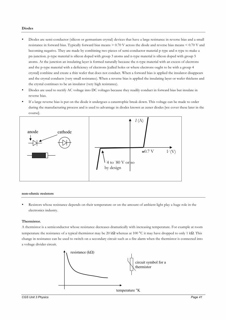
CGS Unit 3 Physics Page 41 Page 41
Diodes
• Diodes are semi-conductor (silicon or germanium crystal) devices that have a large resistance in reverse bias and a small
resistance in forward bias. Typically forward bias means > 0.70 V across the diode and reverse bias means < 0.70 V and
becoming negative. They are made by combining two pieces of semi-conductor material p type and n type to make a
pn-junction. p-type material is silicon doped with group 3 atoms and n-type material is silicon doped with group 5
atoms. At the junction an insulating layer is formed naturally because the n-type material with an excess of electrons
and the p-type material with a deficiency of electrons [called holes or where electrons ought to be with a group 4
crystal] combine and create a thin wafer that does not conduct. When a forward bias is applied the insulator disappears
and the crystal conducts (very small resistance). When a reverse bias is applied the insulating layer or wafer thickens and
the crystal continues to be an insulator (very high resistance).
• Diodes are used to rectify AC voltage into DC voltages because they readily conduct in forward bias but insulate in
reverse bias.
• If a large reverse bias is put on the diode it undergoes a catastrophic break down. This voltage can be made to order
during the manufacturing process and is used to advantage in diodes known as zener diodes [we cover these later in the
course].
anode cathode
non-ohmic resistors
• Resistors whose resistance depends on their temperature or on the amount of ambient light play a huge role in the
electronics industry.
Thermistor.
A thermistor is a semiconductor whose resistance decreases dramatically with increasing temperature. For example at room
temperature the resistance of a typical thermistor may be 20 kΩ whereas at 100 °C it may have dropped to only 1 kΩ. This
change in resistance can be used to switch on a secondary circuit such as a fire alarm when the thermistor is connected into
a voltage divider circuit.
resistance (kΩ)
temperature °K
circuit symbol for a thermistor
I (A)
V (V) ≅ 0.7 V
- 4 to - 80 V or so by design
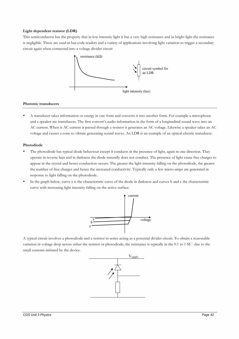
CGS Unit 3 Physics Page 42 Page 42
Light dependent resistor (LDR)
This semiconductor has the property that in low intensity light it has a very high resistance and in bright light the resistance
is negligible. These are used in bar-code readers and a variety of applications involving light variation to trigger a secondary
circuit again when connected into a voltage divider circuit resistance (kΩ)
light intensity (lux)
circuit symbol for an LDR
Photonic transducers
• A transducer takes information or energy in one form and converts it into another form. For example a microphone
and a speaker are transducers. The first convert’s audio information in the form of a longitudinal sound wave into an AC current. When is AC current is passed through a resistor it generates an AC voltage. Likewise a speaker takes an AC
voltage and causes a cone to vibrate generating sound waves. An LDR is an example of an optical-electric transducer.
Photodiode
• The photodiode has typical diode behaviour except it conducts in the presence of light, again in one direction. They
operate in reverse bias and in darkness the diode naturally does not conduct. The presence of light cause free charges to
appear in the crystal and hence conduction occurs. The greater the light intensity falling on the photodiode, the greater
the number of free charges and hence the increased conductivity. Typically only a few micro-amps are generated in
response to light falling on the photodiode.
• In the graph below, curve a is the characteristic curve of the diode in darkness and curves b and c the characteristic
curve with increasing light intensity falling on the active surface. current
voltage a b
c
A typical circuit involves a photodiode and a resistor in series acting as a potential divider circuit. To obtain a reasonable
variation in voltage drop across either the resistor or photodiode, the resistance is typically in the 0.1 to 1 M� due to the
small currents initiated by the device.
Vsupply
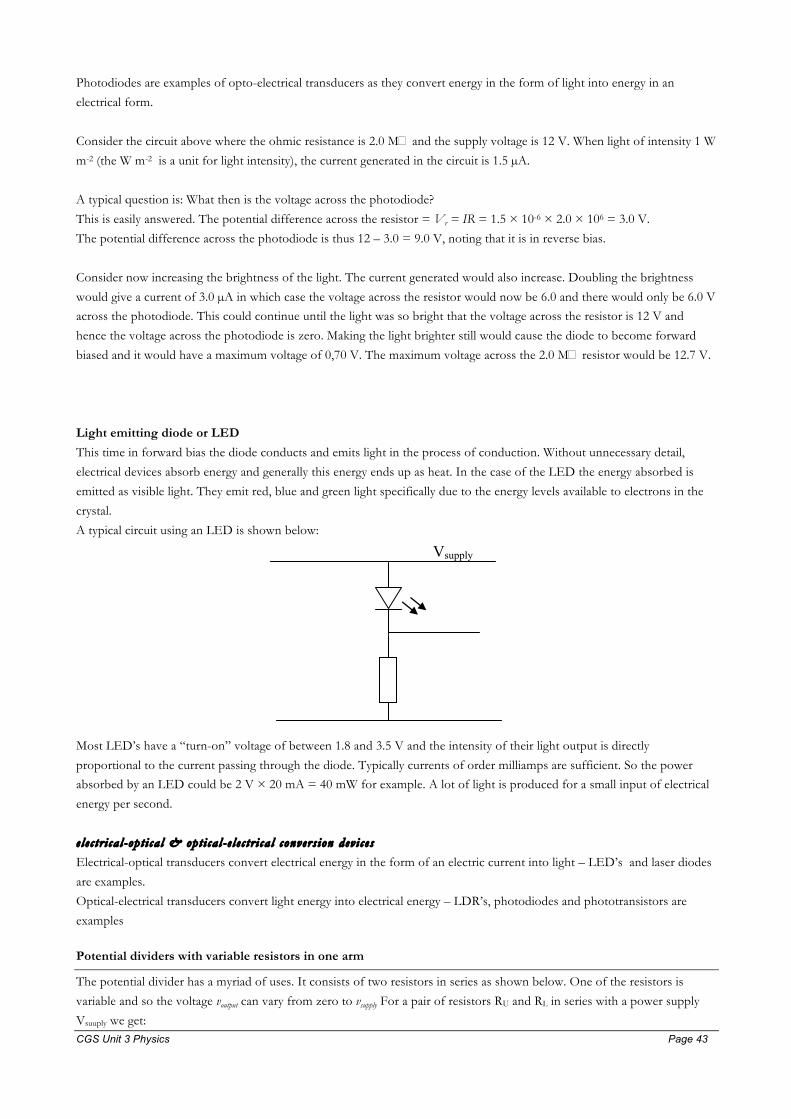
CGS Unit 3 Physics Page 43 Page 43
Photodiodes are examples of opto-electrical transducers as they convert energy in the form of light into energy in an
electrical form.
Consider the circuit above where the ohmic resistance is 2.0 M� and the supply voltage is 12 V. When light of intensity 1 W
m-2 (the W m-2 is a unit for light intensity), the current generated in the circuit is 1.5 µA.
A typical question is: What then is the voltage across the photodiode?
This is easily answered. The potential difference across the resistor = Vr = IR = 1.5 × 10-6 × 2.0 × 106 = 3.0 V.
The potential difference across the photodiode is thus 12 – 3.0 = 9.0 V, noting that it is in reverse bias.
Consider now increasing the brightness of the light. The current generated would also increase. Doubling the brightness
would give a current of 3.0 µA in which case the voltage across the resistor would now be 6.0 and there would only be 6.0 V across the photodiode. This could continue until the light was so bright that the voltage across the resistor is 12 V and
hence the voltage across the photodiode is zero. Making the light brighter still would cause the diode to become forward
biased and it would have a maximum voltage of 0,70 V. The maximum voltage across the 2.0 M� resistor would be 12.7 V.
Light emitting diode or LED
This time in forward bias the diode conducts and emits light in the process of conduction. Without unnecessary detail,
electrical devices absorb energy and generally this energy ends up as heat. In the case of the LED the energy absorbed is
emitted as visible light. They emit red, blue and green light specifically due to the energy levels available to electrons in the
crystal.
A typical circuit using an LED is shown below:
Vsupply
Most LED’s have a “turn-on” voltage of between 1.8 and 3.5 V and the intensity of their light output is directly
proportional to the current passing through the diode. Typically currents of order milliamps are sufficient. So the power absorbed by an LED could be 2 V × 20 mA = 40 mW for example. A lot of light is produced for a small input of electrical
energy per second.
e l e c t r i ca l -op t i ca l & opt i ca l - e l e c t r i ca l convers ion dev i c e s
Electrical-optical transducers convert electrical energy in the form of an electric current into light – LED’s and laser diodes
are examples.
Optical-electrical transducers convert light energy into electrical energy – LDR’s, photodiodes and phototransistors are
examples
Potential dividers with variable resistors in one arm
The potential divider has a myriad of uses. It consists of two resistors in series as shown below. One of the resistors is
variable and so the voltage voutput can vary from zero to vsupply For a pair of resistors RU and RL in series with a power supply
Vsuuply we get:
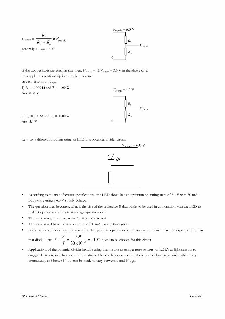
CGS Unit 3 Physics Page 44 Page 44
Voutput = R
R RVL
U L+× sup ply .
generally Vsupply = 6 V.
Vsupply = 6.0 V
0
Voutput Ru
RL
If the two resistors are equal in size then, Voutput = ½ Vsupply = 3.0 V in the above case.
Lets apply this relationship in a simple problem:
In each case find Voutput
1) RU = 1000 Ω and RL = 100 Ω
Ans: 0.54 V
2) RU = 100 Ω and RL = 1000 Ω
Ans: 5.4 V
Vsupply = 6.0 V
0
Voutput Ru
RL
Let’s try a different problem using an LED in a potential divider circuit.
Vsupply = 6.0 V
• According to the manufactures specifications, the LED above has an optimum operating state of 2.1 V with 30 mA.
But we are using a 6.0 V supply voltage.
• The question then becomes, what is the size of the resistance R that ought to be used in conjunction with the LED to
make it operate according to its design specifications.
• The resistor ought to have 6.0 – 2.1 = 3.9 V across it.
• The resistor will have to have a current of 30 mA passing through it.
• Both these conditions need to be met for the system to operate in accordance with the manufacturers specifications for
that diode. Thus, R = 13010309.3
3 =×=
−IV
� needs to be chosen for this circuit
• Applications of the potential divider include using thermistors as temperature sensors, or LDR’s as light sensors to
engage electronic switches such as transistrors. This can be done because these devices have resistances which vary
dramatically and hence Voutput can be made to vary between 0 and Vsupply.

CGS Unit 3 Physics Page 45 Page 45
The transistor: it acts as an amplifier and as a switch
• A transistor is also, like a diode, a semi-conductor. It consists of n-type and p-type silicon material, but the device has
three terminals. These terminals are called the base (B), collector (C) and emitter (E). The transistors we study are called
NPN transistors. There are a myriad of different types of transistor.
• A NPN transistor is a device that may be best thought of as a voltage controlled resistor. It has three terminals called
the base, collector and emitter. When there is no voltage and hence no current on the base, the collector and emitter
circuit have a very high resistance and hence does not conduct. When there is a non-zero voltage on the base, typically
greater than 0.7 V this causes the collector-emitter circuit to conduct. That is the resistance of the collector-emitter
circuit falls drastically from megaohms to a few tens of ohms. In this way the transistor’s ability to conduct is controlled
by the voltage applied to the base.
• A useful analogy is a tap. A small effort to turn the tap handle can yield a large flow of water, provided the pressure of
the water before the tap is large. Adjusting the voltage slightly on the base causes very large variations in the resistance
in the collector-emitter circuit and thus a small variation in an input causes a large variation in an output.
B
E
C B
C
E
• The transistor has properties very similar to a diode except that the RCE is controlled by the voltage Vbase. The graph
which most appropriately describes the behaviour of a transistor is the one shown below. The input voltage is Vbase.
The output voltage is the voltage VCE. Because a transistor is run in series with a second resistor the same voltage divider concept is at work again.
• In essence the transistor is
o a voltage controlled ON of OFF switch or
o between a specified range of input voltages, an amplifier.
A typical Voutput vs Vinput for a transistor being used to amplify an input signal is like the graph shown below. This graph is
sometimes referred to as a transfer curve and arises when a transistor is placed in, yes you guessed it, a potential divider
circuit.
A circuit like the one in the diagram below is sufficient to allow the measurement of a transfer curve.
X
Y
Z
Vinput
Voutput
Vsupply

CGS Unit 3 Physics Page 46 Page 46
Voutput
Vinput
6.0 V
≅1 V
The gradient is a measure of the amount
of amplification. Since a small change on the
input, δVinput will result in an output change δVoutput equal to the gradient × δVinput
≅1.2 V
quiescent point of amplifier is (1.1, 3.0) in this case. The quiescent point is the operating point of the system
cut-off
saturation
The term cutoff is used when the transistor has a large resistance from collector to emitter, the term saturated is used when
the transistor has a small resistance from collector to emitter.
For this circuit the input voltage can be treated as an independent variable. The output voltage can vary from approximately
0 to approximately the supply voltage.
In this course an amplifier circuit will be drawn as below. It has an input with an input voltage and an output with an output
voltage. The input and output lines are both active lines and the lower line represents a neutral line.
Also in this course, the transfer curves for transistors may be redrawn to look like the transfer curves below. For a given
input voltage there is an output voltage. If the input voltage varies sinusoidally then the output voltage will also vary
sinusoidally as well, provided the input voltage remains with the domain of the sloping part of the transfer curve.
Because the device amplifies, the amplitude of the output signal will be much greater than the amplitude of the input signal, which is why it is called an amplifier.
Vin
Vout
-1
1
12
-12
Vout
-1
1
20
-20
Vin
graph 1 graph 2
The first graph is a transfer curve for an INVERTING AMPLIFIER whose gain is 12.
It is inverting because it has a negative gradient and a gain of 12 because the magnitude of the gradient is 12.
The second graph is a transfer curve for a non-inverting amplifier whose gain is 20.
The voltage gain of an amplifier is equal to the madnitude of the gradient of the transfer curve.
The voltage gain of an amplifier is also equal to signal ACinput of amplitudesignal ACoutput of amplitude
• Clipping d i s tor t ion due to incorre c t “b ias ing” or too large an input s i gna l Like many devices, amplifiers have limitations and a correct operating state. Consider an idealised transfer curve for an
amplifier shown below.
1) The supply voltage is 10 V, 2) The quiescent point, or optimum operating state is (1.5, 5.0),
Vinput Voutput neutral

CGS Unit 3 Physics Page 47 Page 47
3) The amplifier gain is –10.
4) The amplifier is an inverting amplifier because an increase in the input results in a decrease in the output and vica-versa.
5) For the system to act correctly as an amplifier with gain –10, input voltages must lie between 1.0 and 2.0 V.
You would set the input side voltage divider to give a 1.5 V bias (there’s that word again, but is not required in the new
study design) to the input signal. All amplifiers in this course are assumed to be correctly biased, that is they are at their
correct operating point on the transfer curve.
10
10
1 2
saturation
cutoff
Vinput
Voutput
You would make sure that the amplitude of the signal was less than 0.50 V. Thus the input signal would always lie between 1
and 2 volts centred on 1.5 V. The output voltage would then be centred on 5 V, varying between 0 and 10 V.
Any input voltage below 1 volt would always yield a 10 V output (the transistor is cut-off) and any input voltage above 2 V
would always yield a 0 V output (the transistor is saturated). Under these circumstances when the input voltage is less than 1
or exceeds 2 V, the output voltage is no longer a linear function of the input voltage and hence distortion results. This type of amplitude distortion is known as clipping. You hear it when you turn the gain of your audio amplifier up to high or if
the input signal has too large an amplitude to begin with. The sound is scratchy and sharp to the ear. Basically the shape of
the output signal is sinusoidal for a sinusoidal input but the top and the bottom, the crests and the troughs of the signal are
flattened off.
The circuit below was used to demonstrate a non-clipped and clipped output. The workings of the circuit are not on the
study design, but the concept of clipping is.
A 10 Hz sinusoidal signal is added to a input voltage of 12 × 1750/21750 = 0.96 V. In the first diagram the amplitude of the
10 Hz signal is 0.1 V and no clipping is evident on the output voltage. In the second diagram the amplitude of the input
voltage is increased to about 0.90 V and this causes the output voltage to be clipped both top and bottom.
The circuit to the left is equivalent to symbol used in this course to the right.
Vinput
Voutput
Vinput Voutput

CGS Unit 3 Physics Page 48 Page 48
In the first diagram a sinusoidal input of amplitude 0.10 V gives a sinusoidal output voltage of amplitude 4.5 V. In the
second diagram the input voltage amplitude has been increased to 0.90 V and the output voltage is now clipped at the top and the bottom of the signal.
output voltage
input voltage
output voltage is
now clipped
note how output voltage is
inverted relative to input
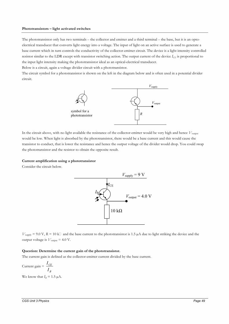
CGS Unit 3 Physics Page 49 Page 49
Phototransistors – light activated switches
The phototransistor only has two terminals – the collector and emitter and a third terminal – the base, but it is an opto-
electrical transducer that converts light energy into a voltage. The input of light on an active surface is used to generate a
base current which in turn controls the conductivity of the collector-emitter circuit. The device is a light intensity controlled
resistor similar to the LDR except with transistor switching action. The output current of the device ICE is proportional to
the input light intensity making the phototransistor ideal as an optical-electrical transducer.
Below is a circuit, again a voltage divider circuit with a phototransistor.
The circuit symbol for a phototransistor is shown on the left in the diagram below and is often used in a potential divider
circuit.
Vsupply
Voutput
R symbol for a phototransistor
In the circuit above, with no light available the resistance of the collector-emitter would be very high and hence Voutput
would be low. When light is absorbed by the phototransistor, there would be a base current and this would cause the
transistor to conduct, that is lower the resistance and hence the output voltage of the divider would drop. You could swap
the phototransistor and the resistor to obtain the opposite result.
Current amplification using a phototransistor
Consider the circuit below.
Vsupply = 9 V
Voutput = 4.0 V
10 kΩ
ICE
IB
Vsupply = 9.0 V, R = 10 k� and the base current to the phototransistor is 1.5 µA due to light striking the device and the
output voltage is Voutput = 4.0 V.
Question: Determine the current gain of the phototransistor.
The current gain is defined as the collector-emitter current divided by the base current.
Current gain = B
CE
II
We know that IB = 1.5 µA.

CGS Unit 3 Physics Page 50 Page 50
The current ICE = the current through the resistor = R
Voutput since there is a 4.0 V drop across the 10 k� resistor. ICE =
310104×
= 0.4 mA = 400 µA.
Thus the current gain is 5.1
400= 267.
• Modulat ion and de-modulat ion o f l ight f rom an e l e c tr i c -opto transducer
The term “modulate” in the context of this course means to vary the amplitude, that is brightness, of a light beam.
This can be done with an LED for instance by varying the current is a circuit containing an LED. In the diagram
below, if R1 were varied then the brightness of the LED would vary as well. We say that the light wave emitted
by the LED has a modulated amplitude. Consider R1 to be a type of microphone such that its resistance is small
when loud sounds are present and visa versa. The LED would be bright when loud and dull when little sound
was present – variations in sound level would produce variation in the light output of the LED. We call the red
light emitted from the LED a carrier wave. In real applications the carrier wave is a microwave or infrared wave
and is used to transmit digital signals between remote controls and appliances, to and from computers to wireless
routers and to and from phones to reception towers and so on.
A photodiode can be positioned to detect the light variations from an LED, as shown below, and since it
responds to the brightness of light, the current produced in the second circuit with the photodiode will
“emulate” or mimic the current variation in the LED circuit. This would result in a variation in the output
voltage of this seconde circuit The pair of circuits is sometimes called an opto-isolator circuit where light is
amplitude modulated in the LED and the information demodulated in the photodiode circuit. This is the essence
of a wireless communication system. The output voltage could be fed into a simple amplifier and its output used
to drive a speaker or recording device.
12 V
R1
LED
photodiode
R2
Voutput
Red light has a frequency in the 1014 Hz range –it has an extremely high frequency. Infrared is in the 1013 Hz and
microwaves have a frequency range of 1010 – 1011 Hz.

CGS Unit 3 Physics Page 51 Page 51

CGS Unit 3 Physics Page 52 Page 52
Summary: STRUCTURES & MATERIALS
This detailed study focuses on the physical properties of materials when forces act on them. The key concept
here is that materials will change shape, i.e. will stretch, compress, shear or twist under the action of external
forces. Eventually materials will fracture if the applied force is sufficiently great. This knowledge of material
properties and analysis of physical data is essential in the design of structures. The unit extends the core area of
motion in one and two dimensions.
• Hooke’s law When a material has a tensile force (force applied away from sample) applied to it, it stretches in the direction of
the applied force. When a compressive force (force applied towards the sample) is applied it is compressed along
the axis of the force. The word “extension” refers to either a compression or a stretch.
For small forces F the amount of change in length �x, or simply x for convenience, is proportional to the size of the
applied force and so:
F = kx.
The constant k is called the spring constant or stiffness of the sample of the material; it has the unit N m-1.
A graph of applied force against x is a straight line for small F and the gradient of the line is also the value of k.
For larger forces the graph may become non-linear. The elastic limit divides the graph into two parts: a lower
part where the graph is linear and k is relevant and beyond this point. Materials extended beyond the elastic limit
will not return to their original shape; they are permanently deformed, while extensions below the elastic limit
will allow the material to return to its original shape when the applied force is removed.
fT
fC
0
force
extension
tensile elastic limit
50
100
150
200
0.010 0.020
compressive elastic limit
The elastic potential energy [or strain energy] stored in the material is always given by the area under a force vs
extension graph.
If the force is in newton and the extension in metre then the area is in N m or Joule, J.

CGS Unit 3 Physics Page 53 Page 53
When the graph is of the form F = kx, the area under the graph is given by the equation:
PEelastic = 2
21 kx , otherwise the strain energy is simply the area under the graph.
Remember the stored potential energy due to a material having undergone a change in shape is called the strain
energy.
• Elastic limit This limit is the point below which a material, when stretched, will return to its natural length and not suffer any
permanent deformation. This point can coincide where the graph becomes non-linear but it is not necessarily the
case. Taking a material beyond its elastic limit will cause a permanent deformation of the material.
• Plastic behaviour Above the elastic limit a material’s force vs stretch curve will eventually become non-linear and the material
when released from the applied force will not return to its natural length. This region is called the plastic phase.
• Brittle and ductile behaviour A brittle material will fracture without going into its plastic phase, that is it will break at a point which is
designated as still responding in a linear way, i.e. Hooke’s Law is still valid.
A ductile material will fracture in the plastic phase, beyond the elastic limit for the material. A brittle fraction will
create two surfaces that can be put back together. A ductile fracture will create two surfaces that cannot be put
back together.
• Structural hysteresis Structural hysteresis is the name given to a graph of loading a material with an applied force vs extension and
then unloading the material. The plot is made as a sequential function. The return path of the graph may not be
the same as the loading part of the graph. The area between the loading and unloading part of the function is the
energy transformed to heat or resulting in permanent damage to the material or sound.
Page 190 of the Jacaranda 2 textbook.
• Stress, strain, Young’s modulus, stiffness The stress acting on a material is simply calculated as the force per unit area. It has the unit N m-2 or pascal (Pa).
This unit is also the unit for pressure. 1 atmosphere is about 1 × 10⁵ Pa.
The relevant area is the area for which the force is normal to it. The size of the area will change when a force is
applied, but the size used for calculation is the relaxed state when the material is not under stress.
stress = AF
=σ N m-2 or Pa
When a stress is applied to a solid it changes shape �l or �l for an object of length l. The fraction �l/l is called
the strain and is a dimensionless number.
strain =lxΔ
=ε
Sometimes the percentage strain is quoted for a given stress this is = 100×llδ
%.

CGS Unit 3 Physics Page 54 Page 54
F
A, cross sectional area
δl
l, natural length
εσ
δεσ
δ
Ell
AF
lkF
=
==
×=
and since and
The quantity E is called Young’s modulus and is a property of a material independent of its shape;
It has the unit N m-2 or Pa.
The quantity k is the stiffness and is a property of a sample of the material and is dependent on the shape of the
material. We all know that a long rubber band will stretch more than a short rubber band made of the same
material; in fact:
AElk =
As a side note the area of a circle A when the diameter d is the measured quantity, as it is in experimental work
given best by the formula:
4
2dA π= .
Also remember that area must be quoted in the unit: m2 and thus a circle with a 3.0 mm diameter has an area of
7.07 × 10⁻⁶ m2.
1) there are 100 cm in a m and 1000 mm in a metre
2) the radius of a circle is exactly half the diameter of a circle!
• Elastic potential energy When a material is stretched or compressed the material stores potential energy. The area under a stress-strain
graph gives the energy stored per unit volume – note this is not the total stored energy but the amount per unit
volume. The obtain the total amount you need to multiply this by the volume of the sample V = A × l.
In the elastic domain of the graph where εσ Y= then the strain energy per unit volume is
221εYPE = J m-3
What this means is that when using a stress-strain graph to calculate the total potential energy stored, first find
the area under the graph and then multiply by the volume of the sample.
Note that the unit for the area under a stress-strain graph is N m-2 but this can be changed to N m per m3 which
is of course our old friend J m-3.

CGS Unit 3 Physics Page 55 Page 55
• Other parameters to describe properties of materials (see word list in notes ) It has become fashionable to talk about 3 properties that materials have. 1) Toughness The measure of toughness is the area under a stress-strain graph up to the point of fracture. That is it is the
strain-energy per unit volume stored at the point of fracture. 2) Streng th or Tens i l e s t r eng th The measure of strength is the stress at the point of fracture. 3) Sti f fnes s or r i g id i ty The measure of stiffness is the gradient of a stress-strain graph.
Tough materials may have less strength than other materials that are not as tough.
stress (MPa)
strain
×
× ×
LEGEND
sample 1: sample 2: sample 3:
materials under tension
materials under compression
O
In the diagram above
sample 1 is the strongest,
sample 3 is the toughest and
sample 2 is the stiffest in tension.
Both samples 2 and 3 are ductile while sample 1 is brittle in tension.
• Stable structures A stable structure is one which is in equilibrium. That is the net force = 0. Below the black dot is in equilibrium
since it is stationary. The three forces W, P and Q add to zero.
W = mg
P
Q
θ°
G clamp
spring balance

CGS Unit 3 Physics Page 56 Page 56
Note for this system the following is true:
Psin� = mg [Newtons’s first law applied vertically]
Pcos� = Q [Newtons’s first law applied horizontally]
W = mg N down
P
Q
θ°
G clamp
spring balance
β°
Note for this system the following is true:
Qcos� +Pcos� = mg [Newtons’s first law applied vertically]
Qsin� = Psin� [Newtons’s first law applied horizontally]
Notice the differences in the two systems and the different equations, but both arising from the same principle.
The principle of equilibrium can be put into practice 2 ways. 1) The total force along a given direction sums to zero or 2) The sum of force components up = sum of force components down 3) The sum of force components right = sum of force components left
• Torque of a force about a point For structures with size, an additional quantity, Torque, is required to analyse equilibrium. Torque is a measure
of the rotational effect that a force can have. We can thus talk about rotational equilibrium where a body rotates
at a constant rate, generally zero.
Torque � is a quantity that measures the size and direction [either clockwise or anticlockwise] of the turning
effect of a force F applied a distance r from an axis of rotation or from a specified point P. The direction of a
torque [in year 12] is either clockwise or anti-clockwise. The direction is best determined by the direction that the
force would rotate the object by itself: in the example below the torque would be considered to be clockwise in
orientation.
F
r
θ
θτ sinrF= N m P
Notice the equation for the size of a torque contains a factor sin�. When the force is parallel to the vector r the
torque is zero. This force cannot cause a rotation only a stretch.

CGS Unit 3 Physics Page 57 Page 57
Consider the diagram below which represents a door of width 2.5 m with a hinge at O.
Here a 20 N force acting on the end of a 2.5 m wide door gives rise to a torque:
� = 2.5 × 20 × sin 90° = 50 N m clockwise torque about the point labelled O in the diagram below.
[note: a N m is not a Joule here, because the force used is the component perpendicular to the distance. Energy
transfers, that is work done by a force, relate only to forces acting in the direction of displacement].
A torque has to be calculated “about a point”. What this means is that a point has to be first chosen and the
product of the distance of the point of application of the force and the size of the force is then made. If the
point M is chosen, the midpoint of the door then the torque about M is 1.25 × 20 × sin 90 = 25 N m.
2.5 m
20 N
O
a door with a hinge at O
M
The principle of rotational equilibrium can be put into practice 2 ways.
1) The total torque about a point in a given rotational axis sums to zero
2) The sum of clockwise torques = sum of anticlockwise torques.
• Newton I : translational equilibrium ΣF = 0 , rotational equilibrium Σ� =0 A structure will be in equilibrium when the sum of the forces acting on it equals zero so that it does not
accelerate and also when the sum of the torques about a point on the structure sum to zero so that it does not
rotate with an increasing rate or decreasing rate of revolution.
• Bridges There are many types of bridge design but the bridge and its load must be supported if it is to be stable. We may
refer to a bridge as a beam and any supports as pylons or struts. Pylons support a beam in compression and
struts support a beam in tension.
a beam with 3 pylons
F1 F2 F3
W
O
O
force vector diagram for bridge
x2
x3

CGS Unit 3 Physics Page 58 Page 58
In the diagram above the bridge has a weight W and the 3 pylons provide upward contact forces F. The sizes of
the three forces are not necessarily the same. But:
F1 + F2 + F3 = W. [Newton’s first law]
If we also include an equation based on the torques of the four forces about O then:
Wx2 – F2x2 – F3x3 = 0 [� clockwise torques = � anticlockwise torques]
• Cantilevers A cantilever is a beam supported at one end such as a diving board or a roof.
Shop sign60 kg
Cantilever mass100 kg
25°
4.0 m
3.0 m
TR
Notes for beginners:
1) The torque about the point where the cantilever joins with the building due to the sign “Café” is
60×9.8×4.0 = 2352 N m clockwise.
2) The vector T is the tension in the oblique strut and hence the force that it exerts on the cantilever.
3) The vector R is the contact force that wall of the building exerts on the cantilever.
4) In this diagram the weight of the cantilever and the force that the sign exerts down on the cantilever is
not shown.
• Cantilevers with struts and ties In some cases a cantilever will be supported with an oblique strut or tie. A strut would be mounted below the cantilever and a tie mounted above the cantilever as shown in the diagram above.

CGS Unit 3 Physics Page 59 Page 59
• Tension and compression
An element in a structure is in tension when an external force is acting on it away from its centre. Likewise an
element is in compression when an external force is acting towards its centre. Materials may have their surfaces
in both tension or compression. For example a beam supported on either side by two pylons will have its top
surface in compression while its surface underneath will be in tension. This is due to the sagging that the beam
will undergo when supported at both ends by pylons P and Q as a result of its weight. A cantilever will be in
tension on the top surface and under compression on the underside again due to the sagging of the element due
to its weight.
This idea is illustrated below:
Q P
T T T T T T T T T T T T C C C C
C C C C C C C C C C C C T T T T
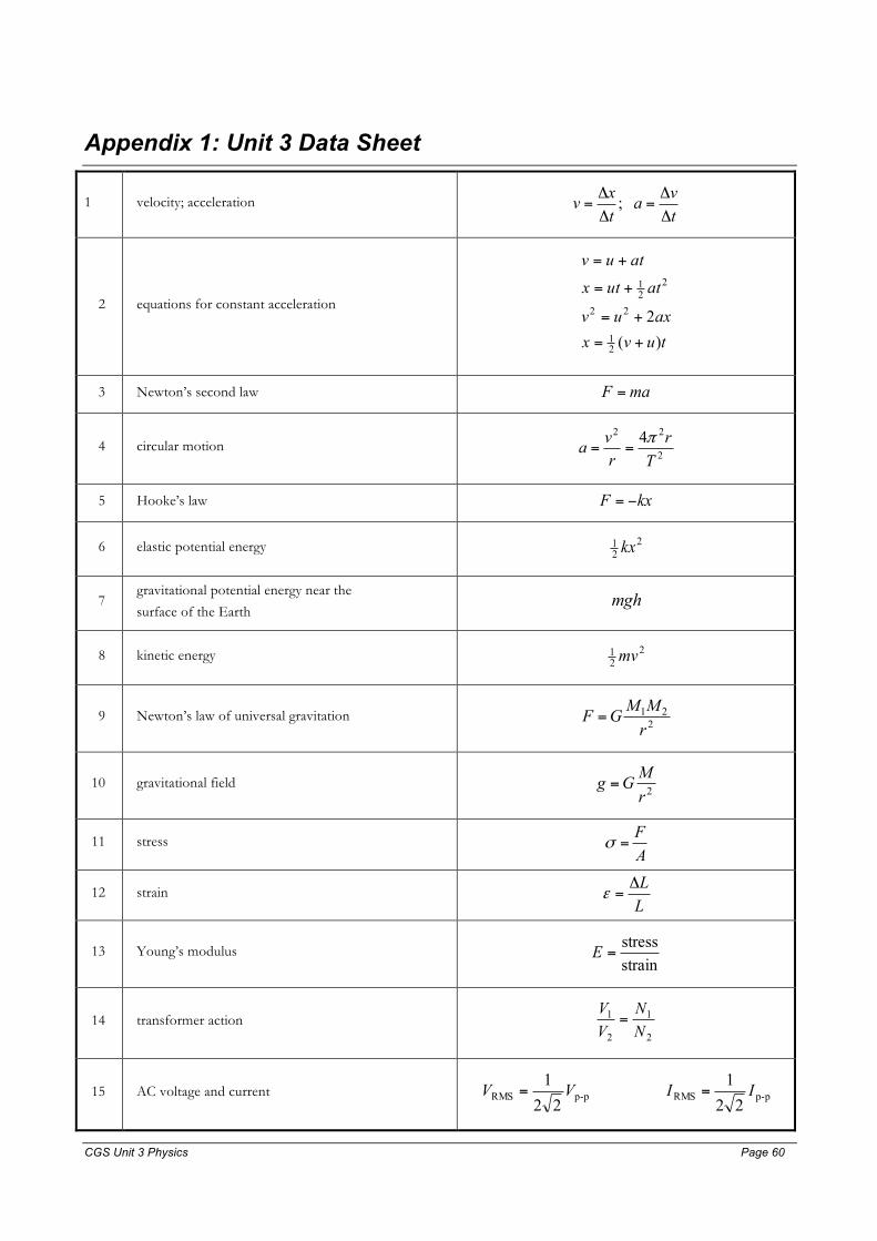
CGS Unit 3 Physics Page 60 Page 60
Appendix 1: Unit 3 Data Sheet
1 velocity; acceleration tva
txv
ΔΔ
=ΔΔ
= ;
2 equations for constant acceleration
tuvxaxuv
atutx
atuv
)(2
21
22
221
+=
+=
+=
+=
3 Newton’s second law maF =
4 circular motion 2
22 4Tr
rva π
==
5 Hooke’s law kxF −=
6 elastic potential energy 221 kx
7 gravitational potential energy near the
surface of the Earth mgh
8 kinetic energy 221 mv
9 Newton’s law of universal gravitation 221
rMMGF =
10 gravitational field 2rMGg =
11 stress AF
=σ
12 strain LLΔ
=ε
13 Young’s modulus strainstress
=E
14 transformer action 2
1
2
1
NN
VV
=
15 AC voltage and current p-pRMSp-pRMS 221
221 IIVV ==

CGS Unit 3 Physics Page 61 Page 61
16 voltage; power VIPRIV ==
17 resistors in series 21T RRR +=
18 resistors in parallel 21T
111RRR
+=
19 capacitors RC=τ:constant time
20 Lorentz factor 21
2
2
1
1
⎟⎟⎠
⎞⎜⎜⎝
⎛−
=
cv
γ
21 time dilation t = to�
22 length contraction L = Lo/�
23 relativistic mass m = mo�
24 universal gravitational constant -2211 kg m N 1067.6 −×=G
25 mass of Earth kg 1098.5 24E ×=M
26 radius of Earth m 1037.6 6E ×=R
27 mass of the electron kg 101.9 31e
−×=m
28 charge on the electron C 106.1 19−×=q
29 speed of light -18 s m 100.3 ×=c
Prefixes/Units
n = nano = 10-9
µ = micro = 10-6
m = milli =10-3
k = kilo = 103
M = mega = 106
G = giga = 109
tonne = 103 kg
END OF DATA SHEET

CGS Unit 3 Physics Page 62 Page 62
Assignment 1 Worksheet: Review of Unit 2 DC circuits A dry cell battery is connected to a light globe as shown below. 8.0 Coulomb passes through the dry cell battery
each second with the switch closed. The cell supplies energy to each Coulomb of charge at a rate of 1.50 J C-1.
switch
globedry cell
Electrons carry a charge of 1.6 × 10⁻¹⁹ C.
Q1. State the current passing through the battery. (1)
Q2. State the potential difference across the battery. (1)
Q3. What is the potential difference across the light globe? (1)
Q4. How many electrons flow through the battery in one second ? (1)
Q5. How much chemical energy is converted to electrical energy each second? (1)
Q6. At what power is the dry cell operating? (1)
Q7. How much energy is transferred into light and heat by the globe in 5 minutes? (1)
Q8. What is the resistance of the globe? (1)
Appreciate the way in which the questions are worded, many mean the same thing.
In the two circuits below, two light globes are connected in series (circuit a) and then in parallel (circuit b) with a
12 V power supply.
(a)
12 V 4.0 Ω
12 Ω
12 V 4.0 Ω 12 Ω
(b)
Q9. Redraw each circuit, using the “electronics style”; that is with a 12 V and earth rail and globes connected
across the rails and then state the total resistance of circuit (a) and then (b) (2)
Q10. Calculate the current passing through the battery in circuit (a) and then (b). (2)
Q11. Calculate the voltage across each of the light globes in circuit (a) and then (b). (2)
Q12. Determine the power transferred to each of the two globes in circuit (a) and then (b. (2+1)

CGS Unit 3 Physics Page 63 Page 63
____________________________________________________________________________________
Q13. Three light-globes having a resistance 3.8 Ω, 68 Ω and 1.2 kΩ respectively are lying around in the physics
lab. There an eager student wires them up to a 10 V power supply to study the combined effect of the resistors
. a) In the first instance all three are wired together in series. What is the effective resistance of the three resistors
in series? What is the supply current from the 10 V power supply? (2 ) b) Next he wires the 3.8 Ω and the 68 Ω resistors in parallel. What is the effective resistance of the two
resistances in parallel? What is the supply current from the 10 V power supply? (2 ) c) For each situation a) and b), calculate the power output of the power supply. (2) ______________________________________________________________________________________
Q14. Consider the circuit below that consists of a power supply and three globes.
4.0 kΩ
2.0 kΩ 6.0 kΩ S
S
Find the following quantities for the circuit when the switch S is closed.
a) Redraw the circuit, using the “electronics style”; that is with a 12 V and earth rail and globes connected across the rails (2)
b) Calculate the potential difference across the battery. (1 ) c) Calculate the total resistance of the circuit. (2 ) d) Calculate the current flowing through each of the three globes in the circuit. ( 2+ 1 + 1 ) e) Calculate the potential difference across each of the three globes in the circuit. ( 2+ 1 +1 ) f) Calculate the total power output of the battery. (2 ) g) Calculate the power transferred to the 6.0 kΩ globe. (2 ) _____________________________________________________________________________________
Q15. The characteristic curve for a new light globe is shown below.
Current (A)Characteristic curve
00.050.1
0.150.2
0.250.3
0.350.4
0.45
0 1 2 3 4 5 6 7 8 9 10Voltage (V)
Cur
rent
(A
)

CGS Unit 3 Physics Page 64 Page 64
a) Give a reason as to whether or not the device is ohmic or non-ohmic. (2 ) b) Estimate the resistance of the device when the potential difference across it is 3.0 V. (2 ) c) Calculate the power transferred to the device when the potential difference across it is 9.0 V. (2 ) ______________________________________________________________________________________
Worksheet 1 – Electronics and Photonics - DC Circuits revision: Answers
Q1 Since we are told that 8.0 C/s passes through the battery the answer is 8.0 Amp.
Q2 Again we are told indirectly that the voltage is 1.5 Volt.
Q3 All of the voltage drops across the single globe, thus 1.5 Volt.
Q4 1 electron: 1.6 × 10⁻¹⁹ C
x electrons: 8 C
Thus secondper electrons100.5
106.10.80.8
106.11
1919
19
×=×
=
×=
−
−
x
x
Q5 There is 1.5 joule for each coulomb and 8 coulomb per second and so
P = V×I = 1.5 × 8 = 12 J s-1 where P is the power transferred.
Q6 Same as above, just reworded: 12 J s-1.
Q7 Energy is transferred at a rate of 12 joule each second. Five minutes is 300 second and so
the total energy is 3600 J or 3.6 × 10³ J.
Q8 The voltage across the globe is 1.5 V and the current through the globe is 8.0 A, thus the resistance of
the globe is 1.5 ÷8.0 = 0.19 Ω
Q9
(a) (b) 12 V 12 V
4.0 Ω 4.0 Ω
12 Ω
12 Ω
The total resistance is 16 � and 3.0 � for the (a) and (b) circuit respectively.
Series circuit (a)
Q10 The total resistance of the circuit is 16 Ω, the supply voltage is 12.0 V, using Ohms Law with Isupply as
the subject ===1612
total
supplysupply R
VI 0.75 A
Q11 V4Ω + V12Ω = 12 and
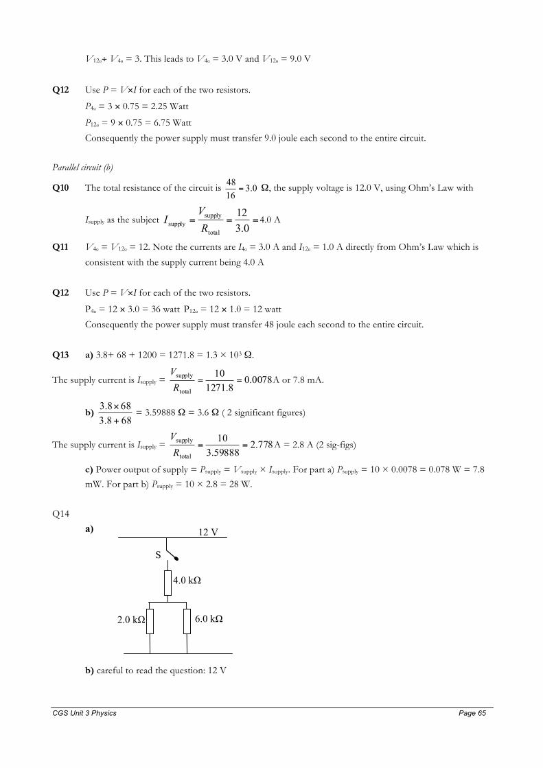
CGS Unit 3 Physics Page 65 Page 65
V12Ω÷ V4Ω = 3. This leads to V4Ω = 3.0 V and V12Ω = 9.0 V
Q12 Use P = V×I for each of the two resistors.
P4Ω = 3 × 0.75 = 2.25 Watt
P12Ω = 9 × 0.75 = 6.75 Watt
Consequently the power supply must transfer 9.0 joule each second to the entire circuit.
Parallel circuit (b)
Q10 The total resistance of the circuit is 0.31648
= Ω, the supply voltage is 12.0 V, using Ohm’s Law with
Isupply as the subject ===0.312
total
supplysupply R
VI 4.0 A
Q11 V4Ω = V12Ω = 12. Note the currents are I4Ω = 3.0 A and I12Ω = 1.0 A directly from Ohm’s Law which is
consistent with the supply current being 4.0 A
Q12 Use P = V×I for each of the two resistors.
P4Ω = 12 × 3.0 = 36 watt P12Ω = 12 × 1.0 = 12 watt
Consequently the power supply must transfer 48 joule each second to the entire circuit.
Q13 a) 3.8+ 68 + 1200 = 1271.8 = 1.3 × 10³ Ω.
The supply current is Isupply = 0078.08.1271
10
total
supply ==RV
A or 7.8 mA.
b) 688.3688.3
+
× = 3.59888 Ω = 3.6 Ω ( 2 significant figures)
The supply current is Isupply = 778.259888.310
total
supply ==RV
A = 2.8 A (2 sig-figs)
c) Power output of supply = Psupply = Vsupply × Isupply. For part a) Psupply = 10 × 0.0078 = 0.078 W = 7.8
mW. For part b) Psupply = 10 × 2.8 = 28 W.
Q14
a) 12 V
S
4.0 kΩ
6.0 kΩ 2.0 kΩ
b) careful to read the question: 12 V

CGS Unit 3 Physics Page 66 Page 66
c) RTOTAL (in k�) = Ω=+×
+ k 5.526264 [note the resistances are in k� not �]
d) I4kΩ = Isupply = 550012
= 2.18× 10⁻³ A = 2.18 mA. I2k� = 1.64 mA, I6kΩ = 0.55 mA [note the milliamp
unit]
e) V4kΩ = I4k� × 4000 = 2.18× 10-3 A ×4000 �= 8.72 V, V2kΩ = V6kΩ = 12 – 8.72 = 3.28 V
f) Psupply = Vsupply×Isupply = 12 × 2.18 × 10-3 = 26 × 10-3 W = 2.6 × 10⁻² W or 26 mW.
g) P6kΩ = V6k� × I6k� = 3.28 × 0.55 × 10-3 = 1.8 mW
Q15 a) The device is non-ohmic because I is not proportional to V, that is R is not a constant for the device.
b) ===17.00.3
IVR The resistance is approximately 18 � (2 significant figures).
c) When V = 9.0 V, I = 0.40 A and so P = V×I = 9 × 0.40 = 3.6 W
______________________________________________________________________________________
Assignment 3 Worksheet: Review of Unit 2 Movement 1) The world record for the men’s 200m sprint is 19.1s.
a. Calculate the average speed of the runner who set this. (1)
b. If the runner accelerates, from rest, to his maximum speed of 11.8 m s-1 in 2.2 s, calculate:
i. the runners acceleration (1)
ii. the runners average speed during this time interval (1)
iii. the distance travelled during these first 2.2 seconds. (1)
2) A car starts from rest at an intersection and accelerates at a rate of 3.5 m s-2 for a period of 5.0 s. It then travels at a
constant speed for the next 10 seconds before coming to rest in 3.0 s at the next intersection. Hint: a quick sketch
graph will help.
a. Determine the speed of the car from t =5 s to t = 10 s. (1)
b. Use the information to calculate the distance between the two intersections. (2)
c. Calculate the average speed of the car when between the two intersections and the number of instances
that the car was actually travelling at that average speed. (2)
3) In a ticker-timer experiment, a cart is rolled down an inclined plane. Attached to the cart is a ticker timer tape. A
portion of the tape is shown below:
A B C D E
AB = 8.0 cm, BC = 10 cm, CD = 12 cm and DE = 14 cm and the ticker timer operates at a frequency of 25 Hertz,
that is there are 25 intervals produced each second.
a. What is the time interval that elapses between each successive pair of dots? (1)
b. What is the average speed of the cart during the period CD? (1)
c. What aspect of the tape tells you that the acceleration of the cart is uniform over the distance AE? (1)
d. What is the acceleration of the cart? (2)
e. What is the exact speed of the cart when the dot labelled C is made? (2)
4) A car is travelling at 100 km h-1.
a. Calculate the speed of the car in m s-1. (1)

CGS Unit 3 Physics Page 67 Page 67
The driver of the car sees a fallen tree 50 m ahead on the road and decides to brake. It takes 0.20 s delay before the
car begins to decelerate, which it does at a constant rate. The car comes to rest 5.0 m from the tree.
b. Calculate the deceleration of the car. (2)
c. Using your answer to b) but this time with the car initially travelling at 110 km h-1 to determine the speed
at which the car strikes the tree because it is travelling too fast. (3)
5) A stationary police car begins pursuit of a speeding motorcyclist. The velocity time graphs of both cars are shown on
the one axes below. At t = 0 s, the motorcyclist passes the stationary police car. v m s-1
t s
30
42
12
police car
motorcyclist
a. At what time are the two vehicles travelling at the same speed?
b. Determine the time it takes for the police car to catch up to the motorcyclist. (3)
c. Calculate the distance travelled by the police car to catch up to the motorcyclist. (1)
6) Consider the velocity time graph of a student who is late for class. At t =0 he is at his locker and runs in a straight
line from the locker to his physics class. However, he forgot his calculator and has to go back and get it.
t (s)
v (m s-1)
5 10 15
0 -5
-15 -10
5
a. What is the magnitude of his acceleration during the fourth second? (1)
b. What is the total distance travelled by the student in the first 9 seconds? (1)
c. How far is the student from his locker after 9 seconds? (1)
d. What is the average speed of the student in the last 3 seconds? (2)
7) A car which is travelling at 40 km h-1 accelerates up to 100 km h-1. It does so over a 100 m interval. (1.0 m s-1 = 3.6
km h-1)
a. What is the average acceleration of the car? (2)
b. For how much time did the car accelerate? (2)
8) A ball is thrown vertically up in the air at a speed of 17 m s-1. Take the acceleration due to gravity to be 10 m s-2.
a. Calculate the time taken to reach maximum height. (2)
b. Calculate the maximum height of the ball above from where it was thrown.(2)
c. Discuss what would happen to both your answers to parts a) and b) if air resistance is significant. (2)
9) A ball is dropped from rest 150 m above the ground. [ignore air resistance for these calculations]Take the
acceleration due to gravity to be 10 m s-2.
a. Calculate the time taken for the ball to hit the ground. (2)
CGS Unit 3 Physics Page 68 Page 68
b. Calculate the speed of the ball the moment before it hits the ground.(2)
c. Discuss what would happen to both your answers to parts a) and b) if air resistance was a significant
factor. (2)
10) A car is driving down the straight at Albert Park. During a period of time it has an average velocity of 80 m s-1 and
an acceleration of 3.0 m s-2. Explain what it is about the description of this problem that does not allow you to
obtain a single answer. (3)
11) Trevor runs towards a plane mirror at 4.2 m s-1 in a westerly direction.
a. State the velocity (size and direction) that the image of Trevor moves towards the mirror. (1)
b. State the velocity that Trevor would measure for his image moving towards him. (1)
12) A ball is dropped from rest 25 m above the ground. At the same instant a second ball is thrown upwards at 12 m s-
1. The first ball is vertically above the second ball. The balls collide in midair.
a. At what time after release do the two balls collide? (2)
b. What is the speed of the two balls just prior to collision?(2)
c. How high above the ground are they when they collide?(2)
Solutions 1. a) 200/19.1 = 10.5 s b) 5.4 m s-2, 5.9 m s-1, 13 m (technically, the answers are given to 2 sig-figs in part b).
2. a) v = u +at , so v = 0 +3.5 × 5.0 =17.5 m s-1.
b) The total distance is the sum of the three parts. d = ½ ×3.5 × 52 + 17.5 × 10 + 325.17× = 245 m. c) vav =
==18245
ts
13.6 m s-1
3. a) 1/25th s = 0.040 s b) 3.0 × 102 cm s-1 c) The distance between successive intervals increases at a
uniform rate i.e. at 2 cm per interval. d) 1.25 × 103 cm s-2 e) 2.75 × 102 cm s-1.
4. a) 100/3.6 = 28 m s-1.
b) During deceleration the car travels a distance of 50 – 5 – 0.2 × 27.7 = 39.5 m. Using asuv 222 += to give
suva 2/22 −= = (02 – 27.72/(2×39.46) = -9.7 m s-2
c) at 110 km h-1 = 30.55 m s-1 with a 0.20×30.55 delay distance before braking gives a distance to the tree of 50 –
6.1 = 43.9 m. If you decelerate at 9.7 then : 2×-9.7×43.9 = v2 – 933.3 , so v 0.97.8513.933 =−= m s-1 or 32
km h-1 !!!!!
5. a) 8.6 sec b) For the police car to catch to motorcyclist, it must travel the same distance as the cyclist so : 30t =
distance travelled by cyclist. ½ × 12 × 42 + 42(t – 12) = the distance travelled by the police car. Thus 12t = 504 – 252 , so t =
21 s. c) 630 m
6. a) 5.0 m s-2 b) The total distance travelled is equal to the area under graph from t = 0 to t = 9 s. This is 37.5 m
c) The student’s total displacement is = 2.5 m m; he is still 2.5 m from his locker. d) In the last three seconds, the
student covers a distance of 10 m. The average speed is 3.3 m s-1.
7. a) 3.2 m s-2 b) 5.1 s
8. a) 1.7 s b) 14.4 m c)Both the time and the height would be smaller if air resistance were to be included.
This is because the object we have a deceleration greater in magnitude than 10 m s-2.

CGS Unit 3 Physics Page 69 Page 69
9. a) Use 0 because ;2221 ==⇒+= u
astatuts ; t =
30010
= 5.5 s. b) 54 m s-1.
c) It would take a longer time to fall because the acceleration would be variable and less than 10 m s-2. Because the
acceleration was smaller on average the speed that the ball would hit the ground would also be less.
10. Can’t do – insufficient information – in kinematics questions you need to know 3 things about a problem in order
to find the remaining parameters.
11. a) 4.2 m s1 east b) 8.4 m s-1 east
12. a) t = 2.08 s b) 12 – 10×2.08 = -8.8 m s-1 for the ball originally thrown up and –20.8 m s-1for the ball released
from 25 m. c) 3.3 m, the projected ball goes up and is on the way down when it is hit by the dropped ball. * a
tougher problem

CGS Unit 3 Physics Page 70 Page 70
Assignment 3 Worksheet: Review of Unit 2 Forces
1) State Newton’s first law and describe what it tells us. Give an example of where is would be used. (2)
2) An apple is falling vertically. Draw a vector diagram for the 2 significant forces that act on the apple. Label the forces using the notation F a acting on b. (2)
3) A person is standing upright and is stationary. Draw a vector diagram for the 2 significant forces acting on the
person. (2)
4) 75 kg Sonja happens to be an astronaut who has recently returned from a trip to the Moon.
Data: gearth = 9.8 N kg-1, gmoon = 1.6 N kg-1
a. What is the Sonja’s mass when she is located on the moon? (2)
b. What is the weight of Sonja when she is on the earth? (2)
For questions 5 to 7, calculate the magnitude and direction of the net force acting on the objects.
5)
6)
4.7 N 2.8 N friction force applied force
block
apple
1.26 N
0.34 N
7)
15.0° 15.0°
F=18 000 N
F = 18 000 N PLAN VIEW
A ship being pulled by two tugboats.
8) A car is shown in the diagram below. Find the value of the unknown force or forces for each situation. Remember to
quote both a size and direction ( ↑=up,↓= down, ←= left, →right )
a)
9800 N
N
Car is stationary
b)
12 400 N
N Car is moving at constant speed
800 N driving force
A
c)
840 N
N
Resultant force on car is 320N to the right
500 N driving force
A
9) In the following problem, illustrated in the diagram below, the net force acting on the grey disc is zero.

CGS Unit 3 Physics Page 71 Page 71
10.0 N
16.0 N
F N
30°
a. Calculate the size of the horizontal component of the force F. (2)
b. Calculate the size of the vertical component of the force F. (2)
c. Calculate the magnitude of the force F. (2)
10) Explain the meaning of each term in the equation: This equation is Newton’s second law. (2)
ΣF = ma = tpΔΔ
11) State Newton’s third law of motion and give an example of where it is applicable. (2)
12) A 70 kg runner accelerates from rest at a rate of 8.5 m s-2. What is the average value of the net force acting on the
runner? (2)
13) A student is pulling a block of wood across a table at a constant speed by applying a force of
4.2 N to a string connected to the block.
a. What is the size of the net force acting on the block? (2)
b. What must be the magnitude of the sliding friction force? (2)
14) A 2.40 kg shot-put is falling, having dropped from a balcony during an experiment. Take g = 9.80 N kg-1
a. What is the weight of the shot-put? (1) The ball is measured, using radar techniques to have an acceleration downwards of only 6.0 m s-2 due to the effects
of air resistance.
b. What is the size of net force acting on the ball? (1)
c. Draw a force diagram showing forces acting on the ball. (2)
d. What is the size of the air drag force acting on the ball? (1)
15) A 0.50 kg block of wood is stationary on an inclined plane elevated at 20ο.
20°
Calculate the size of the static friction force acting on the block. Take g = 9.8 N kg-1. (1)
4.2 N Friction

CGS Unit 3 Physics Page 72 Page 72
16) A tennis player is bouncing a ball in preparation to serve the ball. The ball has a mass of 50 g and strikes the
ground at a speed of 2.5 m s-1 and rebounds at a speed of 2.2 m s-1 leaving contact with the ground 0.015 seconds
later than when it first contacted the ground. Take g = 10 N kg-1.
a. What is the change in velocity and hence the acceleration of the tennis ball when in contact with the
ground? (2+1)
b. Determine the average net force acting on the ball when it is in contact with the ground. (1)
c. Determine the average upward contact force acting on the ball when it is in contact with the ground. Why
are your answers to b) and c) different? (2 +2)
17) A tennis ball (mass = 0.10 kg) is travelling at a velocity of 40 m s-1 east. It strikes a tennis racquet and rebounds
with a velocity of 30 m s-1 west. The ball is in contact with the racquet for 20 ms. Remember to specify size, direction and unit for all questions.
a. Determine the change in velocity of the ball.
b. Determine the acceleration of the ball.
c. Calculate the average net horizontal force acting on the ball]
d. Calculate the initial, final and hence the change in momentum of the ball.
e. Determine the impulse of the tennis racquet on the ball and the impulse of the tennis ball on the racquet.
f. Use e) to determine the average net horizontal force acting on the ball by the tennis racquet.
Useful equations
221
2-1221
22
22
down s m 9.8 gravity todueon accelerati
constant00
21
21
22
mvKE
mvp
FF
vaFif
maF
atvtatuts
asuvtsuvv
atuv
av
=
=
=
−=
=⇔=⇔=
=
−=+=
+=
=+
=
+=
→→
∑∑

CGS Unit 3 Physics Page 73 Page 73
Solutions Q1 Newton’s first law tells us that a body will maintain constant velocity, that is zero acceleration when the net force acting
on it is zero. The law also states the inverse.
Q2
Aair on apple
Wearth on applet
Q3
N = Fground on person
W = Fearh on person
Q4 a) still 75 kg. b) 735 N
Q5 1.9 o the right.
Q6 0.92 N down
Q7 2 × 18000cos 15° = 34773 = 34.8 kN to the right using 3 sig figs.
Q8. a) N = 9800 N up b) N = 12 400 N up and A = 800 N left
c) N = 8400 N up and A = 180 N left
Q9 a) Fh = 10cos30° = 8.66 N left b) F v = 16 – 10sin30° = 11 N up
c) ⏐F⏐ = 14 N
Q10. ΣF is the net force acting on the body of mass m with subsequent acceleration a . The quantity tpΔ
Δ is the time rate of
change of momentum. The law tells us that net forces are responsible for accelerations and that mass effects the size of the
acceleration and also that the net force is equal to the time rate of change of momentum.
Q11. Newton’s Third Law states that forces of a particular type act in pairs on pairs of objects. If the planet exerts a force
on an apple, the apple exerts a force on the planet. Each of the two forces are equal in size but opposite in direction and
most importantly one force acts on the apple and the other force acts on the earth.
Q12. 595 N, in the direction of the acceleration.
Q13. a) 0 N b) 4.2 N Q14. a) 23.5 N down
b) 14.4 N down
d) 9.12 N up
Q14 c)
Aair on shotput
Wearth on shotput
Q15. The net force parallel to the plane = 0N , Friction = 0.50 × 10 × sin20°
Friction = 1.71N = 1.7 N up the incline.
Q16. a) Δv = 2.2 - -2.7 = 4.7 m s-1 up, a = 313 m s-2 up. b) ΣF = 15.7 N up.
c) N = 16.2 N up : remember the weight of the ball is 0.50 N down.
Q17 a) 70 m s-1 west b) 3.5 × 10³ m s-2 c) 350 N west
d) 4.0 Ns east, 3.0 Ns west and 7.0 Ns west
e) 7.0 Ns west, 7.0 Ns east
f) F = 7.0 Ns West ÷ 20 ms = 350 N west as in part c)

CGS Unit 3 Physics Page 74 Page 74
Assignment 4 Worksheet 1: Collisions A car of mass 1400 kg collides with a stationary car of mass 800 kg.
The collision can be modelled as an isolated collision. In the graph below, the velocity of the cars before, during and after the collision are given. The collision occurs over a time
of 14/100th of a second.
Collisions from the perspective of TIME
1) Calculate the initial momentum of car A and car B and hence the total momentum of the two cars before the
collision. Note: you will have to use the parameter vA.
2) i) Calculate the final momentum of car A and car B and hence the total momentum of the two cars after the
collision. ii) Use the assumption that the collision is an isolated one to determine the velocity of car A before the
collision.
3) Determine the change in momentum of car A and car B.
4) Calculate the Impulse of car A acting on car B and of car B acting on car A.
5) Determine the average force of car A acting on car B and the average force of car B acting on car A during the
collision.
6) Find the acceleration of both cars during the collision.
7) Calculate the distances travelled by both cars during the collision.
Collisions from the perspective of SPACE – distance travelled during a collision
8) Calculate the initial kinetic energy of car A and car B and hence the total kinetic energy of the two cars before the
collision.
9) Calculate the final kinetic energy of car A and car B and hence the total kinetic energy of the two cars after the
collision.
10) Determine the change in kinetic energy of car A and car B.
11) Calculate the amount of energy that has been transformed from the initial kinetic energy of car A into other forms.
State what the transformed energy has done.
12) Calculate the work done by car A acting on car B and the work done by car B acting on car A.
13) Find the distance travelled by both cars during the collision using your answer to part 5). 14) Find the average acceleration of both cars during the collision (using suvat, not Q6.)
15) Calculate the time during which the collision occurs (using suvat, not diagram)
16) Explain clearly what is meant by an isolated collision and a consequence of that. Further explain whether the
collision is elastic or inelastic.
vA m s-1
v (m s-1)
t (s)
vA
10 7
10014
Car A Car B
Car A Car B

CGS Unit 3 Physics Page 75 Page 75
Solutions 1) pA = 1400va Ns, pB = 0 Ns and so ptotal = 1400va Ns.
2) i) pA = 1400×7 = 9800 Ns, pB = 800×10 = 8000 Ns and so ptotal = 17 800 Ns. ii) For an isolated collision, the total
momentum before the collision is equal to the total momentum after the collision, thus 1400vA = 17 800 ⇒ vA =
12.7 m s-1.
3) ΔpA = pfinal - pinitial ⇒ ΔpA = 9800 - 1400×12.7(1) = -8 000 Ns. ΔpB = pfinal - pinitial ⇒ ΔpB = 8000 – 0 = 8000 Ns.
4) Impulseon car A = ΔpA = -8000 Ns, likewise: Impulseon car B = ΔpB = 8000 Ns.
5) The average net force is = timecontact
impulse
= 8000÷ (14/100) = 57 100 N on car B and –57 100 N on car A quoted to
3 significant figures.
6) The acceleration of car A = -57 100 ÷ 1400 = -40.8 m s-2 which is a deceleration. For car B the acceleration = 57
100 ÷ 800 = 71.4 m s-2.
7) For car A use the equation: 38.18.4027.127
22
222222 =
×
−=
−=⇒+=
−auvsasuv m. For car B, use the equation:
70.08.712010
22
222222 =
×
−=
−=⇒+=
−auvsasuv m. Note the two cars travel different distances during the
collision.
8) KEA = 0.5×1400×12.712 = 113, 000 J to 3 sig fig accuracy. The kinetic energy of the stationary car is 0 J.
9) The final kinetic energies for the two cars are: KEA = 0.5×1400×72 = 34,300 J and KEB = 0.5×800×102 = 40,000 J.
Thus the total kinetic energy of the two cars after the collision is 74,300 J.
10) ΔKEA = 34,300 – 113,000 = -78,700 J. ΔKEB = 40,000 – 0 = 40,000 J.
11) Of the 113,000 J initial kinetic energy of car A 34,300 has been retained by car A, 40,000 J has been transformed
into kinetic energy of car B. This leaves 38,700 J presently unaccounted for. This energy has most likely been
transformed into heat, sound and permanent deformation of the car chassis and shell.
12) WA = ΔKEA = -78,700 J. WB = ΔKEB = 40,000 J.
13) sA = WA/FA = -78,700/-57,100 = 1.38 m. For car B, sB = 40,000/57,100 = 0.70 m.
14) The acceleration of car A = -57 100 ÷ 1400 = -40.8 m s-2 which is a deceleration. For car B the acceleration = 57
100 ÷ 800 = 71.4 m s-2.
15) We can calculate the collision time by noting that car b accelerates at a rate = 71.4 and starting from rest acquires a
final velocity of 10 m s-1. Thus 14.04.71010=
−=
−=
auvt s, consistent with the information given in the question.
16) An isolated collision is one where the total momentum of the system is conserved, this coming about because
external forces acting on the system can be ignored. An elastic collision is one where the total kinetic energy after a
collision equals the total kinetic energy before a collision. No energy is ultimately transformed into heat, sound and
there is no permanent deformation or damage done to the colliding bodies.
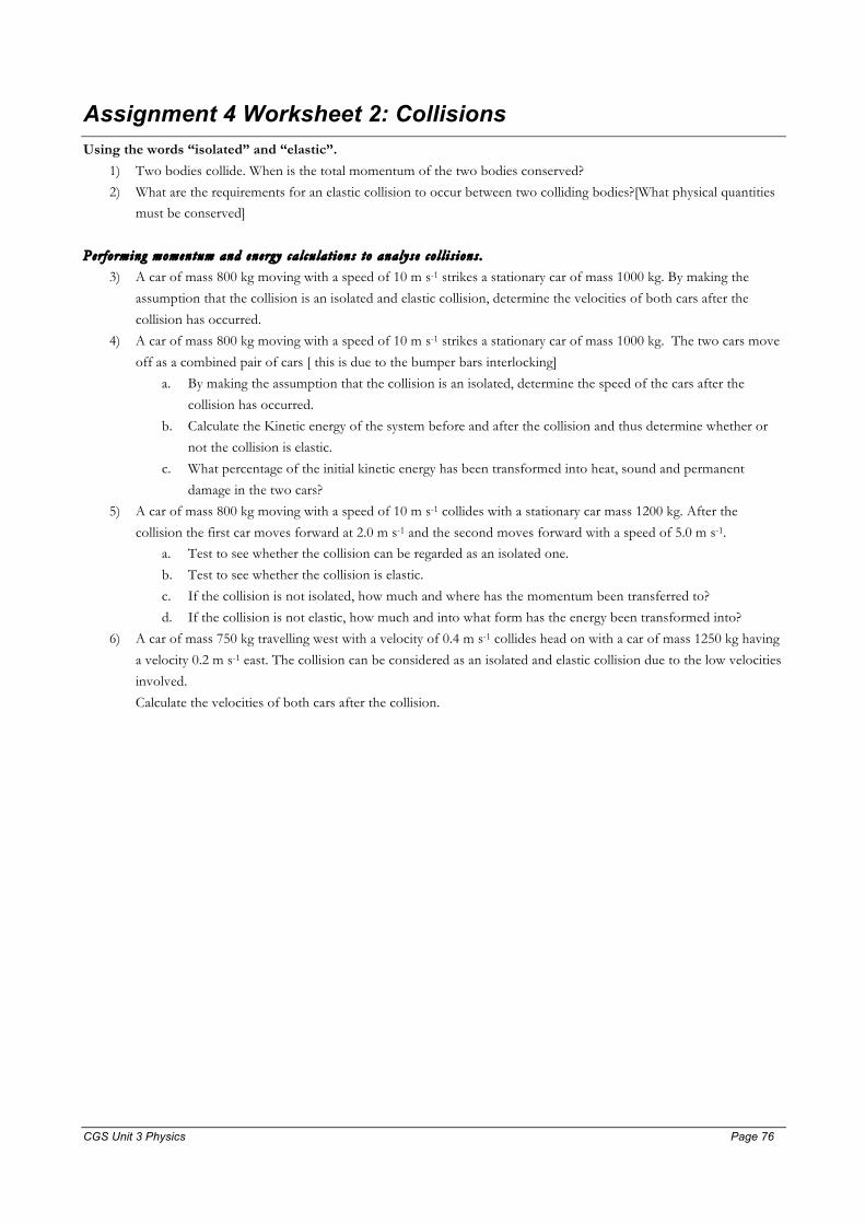
CGS Unit 3 Physics Page 76 Page 76
Assignment 4 Worksheet 2: Collisions Using the words “isolated” and “elastic”.
1) Two bodies collide. When is the total momentum of the two bodies conserved?
2) What are the requirements for an elastic collision to occur between two colliding bodies?[What physical quantities must be conserved]
Per forming momentum and energy ca l cu la t ions to analyse co l l i s ions .
3) A car of mass 800 kg moving with a speed of 10 m s-1 strikes a stationary car of mass 1000 kg. By making the
assumption that the collision is an isolated and elastic collision, determine the velocities of both cars after the
collision has occurred.
4) A car of mass 800 kg moving with a speed of 10 m s-1 strikes a stationary car of mass 1000 kg. The two cars move
off as a combined pair of cars [ this is due to the bumper bars interlocking]
a. By making the assumption that the collision is an isolated, determine the speed of the cars after the
collision has occurred.
b. Calculate the Kinetic energy of the system before and after the collision and thus determine whether or
not the collision is elastic.
c. What percentage of the initial kinetic energy has been transformed into heat, sound and permanent
damage in the two cars?
5) A car of mass 800 kg moving with a speed of 10 m s-1 collides with a stationary car mass 1200 kg. After the
collision the first car moves forward at 2.0 m s-1 and the second moves forward with a speed of 5.0 m s-1. a. Test to see whether the collision can be regarded as an isolated one.
b. Test to see whether the collision is elastic.
c. If the collision is not isolated, how much and where has the momentum been transferred to?
d. If the collision is not elastic, how much and into what form has the energy been transformed into?
6) A car of mass 750 kg travelling west with a velocity of 0.4 m s-1 collides head on with a car of mass 1250 kg having
a velocity 0.2 m s-1 east. The collision can be considered as an isolated and elastic collision due to the low velocities
involved.
Calculate the velocities of both cars after the collision.
CGS Unit 3 Physics Page 77 Page 77
Solutions 1) The total momentum of a system is conserved when is system is isolated.
2) An elastic collision occurs in an isolated system when Kinetic Energy is conserved.
3) V1,after = 1.191010
10008001000800
−=−=×+
− m s-1.
V2,after = 9.898010
18008008002
==×+
× m s-1.
Note that 8.9 - -1.1 = 10 m s-1, which is the speed of approach = speed of separation.
4) (a)Vafter = 4.41800800010
1000800800
==×+
m s-1.
(b) KEbefore = 000,401080021
21 22 =××=mv J.
KEafter = 800,174.4)1000800(21
21 22 =×+×=mv J.
From the above, the collision is not elastic because the kinetic energy after the collision is not equal to the kinetic
energy before the collision.
(c) %Energy transformed = %6.55%1
10040000
1780040000%1
100energy initial
lostEnergy =×
−=× .
5) a. To test to see whether a collision is isolated, you need to see whether the final momentum of the system is equal
to the initial momentum of the system.
Piniial = 800×10 = 8000 Ns, Pfinal = 800×2 + 1200×5 = 1600 + 6000 = 7600 Ns.
Therefore, the system is is not an isolated one. 400 Ns will have been transferred to the earth during the collision.
b. To test whether a collision is elastic or not, the final kinetic energy should be equal to the initial kinetic energy.
KEinitial = 40000 J.
KEfinal = 1600 + 15000 = 16600 J. Thus the collision is not an elastic one. 23400 J of energy is transformed into
heat, sound and physical damage.
6) To use the equations for an elastic collision, body 2 must be stationary. This can be achieved if we subtract 0.20 m
s-1 east from both cars.
So V1 = 0.60 m s-1 west, V2 = 0 m s-1.
After the collision: 60.012507501250750/
1 ×+
−=V west + 0.20 m s-1 east
V1/ = -0.25×0.60 – 0.20 west = -0.35 m s-1 west or 0.35 m s-1 east.
wests m 0.25 east 0.2 west 0.600.75
east s m 20.0 west 60.012507507502
1-
1-/2
=+×=
+×+
×=V
Note the speed of separation = the speed of approach = 0.60 m s-1.

CGS Unit 3 Physics Page 78 Page 78
Assignment 4 Worksheet 3 Collisions – Energy Perspective A 0.200 kg ball drops from a height of 2.00 m and rebounds to a height of 1.65 m, bouncing off the floor with a contact
time of 0.124 s.
1. Draw a force vector diagram for when the ball is falling; ignore air resistance.
2. Calculate the gravitational potential energy of the ball at a height of 2.00 m.
3. Calculate the speed, momentum and kinetic energy of the ball just as it about to hit the floor.
4. Draw a force vector diagram for when the ball is in contact with the floor.
5. Calculate the speed, momentum and kinetic energy of the ball just as it leaves the floor after rebounding.
6. Draw a force vector diagram for when the ball is travelling upwards; ignore air resistance.
7. Calculate the average net force acting on the ball when in contact with the floor.
8. Calculate the average floor to ball contact force when the ball is in contact with the floor.
9. Calculate how much energy is transformed into heat and sound during the collision.
Work, Kinetic Energy Gravitational Potential Energy and Power
10. What work is done by a force of 12 N west which pushes a box 6.0 m west?
11. What work is done by a force of 16 N south which pushes an object 20 cm south?
12. How much work is done when a bricklayer lifts a brick of mass 4.0 kg a vertical height of 1.5 m?
13. How much work is done when 1000 kg of coal is lifted from the bottom of a mine 300 m deep?
14. How much work is done by a force which causes a mass of 30kg to have an acceleration of 1.5 m s-2 south while it is displaced 0.60 m south?
15. 240 J of work is done on a body of mass 8.0 kg causing it to move 12 m in a south-west direction. Calculate the
constant acceleration of the body over this distance.
For questions 16 to 18
Below is a graph of the net force acting when a 10 kg block is pushed across a polished floor.
Net force, N
Displacement, m
20
20
16. Calculate the work done by the net force on the body after it has travelled 20m.
17. If the frictional force was 3.0 N, what was the magnitude of the applied force
18. If the mass of the body is 10 kg was is the acceleration of the body?
19. Determine the kinetic energy of a 0.20 kg billiard ball moving with a speed of 3.0 m s-1
20. A 60 kg runner starts from rest and in the first 1 second acquires a speed of 5.0 ms-1. By the end of the 2nd second
she is travelling with a speed of 10 ms-1.
a. Calculate the change in momentum during the 1st second and then during the 2nd second and hence the
average force exerted on her by the track during the 1st and 2nd second.
b. Calculate the change in kinetic energy of the athlete in the 1st second and then in the 2nd second. Discuss
your result.
c. Calculate the distance travelled in the 1st second and the distance travelled during the 2nd second.

CGS Unit 3 Physics Page 79 Page 79
d. Calculate the work done by the athlete in increasing her speed during the 1st second and then during the
2nd second. Discuss your result.
e. Calculate the average power generated by the athlete to increase her speed during the first second and
then the 2nd second. Discuss your result.
Gravitational potential energy and Kinetic energy
21. A 2.5 kg block suspended at rest 9.0 m above the ground.
a. What is its 1) gravitational potential energy and its 2) kinetic energy and its 3) total mechanical energy?
The block is released.
b. At a height of 5.0m above the ground, what is its gravitational potential energy and its kinetic energy and
its total mechanical energy?
c. The block is just about to hit the ground, calculate the three types of energies again. Use this to determine the speed of the block.
d. In general show that if an object is released at rest from a height h it will hit the ground with a speed
gh2
e. In general show that if an object is thrown vertically up at a speed v that it will attain a maximum height
gv2
2
Stored energy – a bumper bar problem
22. The bumper bars on cars can be modelled as an elastic medium (That is the compression force vs. compression is
a linear graph). The bumper bar of a particular car has k = 8.50 × 10⁴ N m-1. The car (1300 kg) is about to park at
Safeways in Box Hill and is travelling at a speed of 0.600 m s-1 into a parking space. The end of the space is a solid
wall.
a. Calculate the kinetic energy of the car.
b. The driver fails to brake and the bumper bar of the car compresses. Calculate the maximum compression
of the bumper bar assuming all of the kinetic energy of the car is transformed into potential energy. c. When the car is travelling at a speed of 0.300 m s-1, what is the energy stored in the bumper bar?
Solutions
1.
v
W
2. PE = mgh = 0.20×9.8×2.00 = 3.92 J
3. KE = 3.92 J, ⇒ 26.62==
mKEv m s-1 down
⇒ 25.126.620.0 =×== mvp N s down
4.
W
N
5. KE = 0.2×9.8×1.65 = 3.23 J [ΔKE = -ΔPE]
⇒ v = 5.7 m s-1 up and
⇒ p = 1.13 N s up

CGS Unit 3 Physics Page 80 Page 80
6.
v
W
7. 2.19124.0
25.113.1=
−=
Δ
Δ=Σ
−
tpF N
8. Use the vector diagram in question 4 to write:
ΣF = N – W ⇒ 19.2 = N – 2.0 ⇒ N = 21.2 N up. [ the contact force is much greater than the weight here because
the ball is accelerating up while it is in contact with the floor.
9. The energy lost, that is transformed into heat and sound = 3.92 – 3.23 = 0.69 J.
10. W = F×x = 12×6 = 72 Nm or J.
11. W = F×x = 16×0.20 = 3.2 J.
12. W = ΔPE = mgh = 4×9.8×1.5 = 59 J
13. W = ΔPE = mgh = 1000×9.8×300 = 2.94 MJ or 2.94 × 10⁶ J.
14. W = ΣF×x = ma×x = 30×1.5×0.60 = 27 J.
15. W = 240 = 8×a×12 ⇒ a = 2.5 m s-2.
16. Area under the graph = work done = 400 J
17. ΣF = 20 N and ΣF = Applied force – Friction ⇒ 20 = FA – 3 ⇒ FA = 23 N.
18. ΣF = 20 N; m = 10 kg ⇒ a = 2.0 m s-2.
19. KE = 2
21mv = 0.5×0.20×32 = 0.90 J.
20. (a) 300 Ns during both the first and 2nd second. Thus the average force is 300 N for both 1 second time intervals.
(b) ΔKE = 0.50×60×(52 – 02) = 750 J during the first second.
ΔKE = 0.50×60×(102 – 52) = 2250 J during the 2nd second. The change in kinetic energy during the 2nd second is 200% or 3
times greater than in the first second, even though the applied force of the earth acting on the athlete is a constant 300 N.
(c) distance travelled = vav×1 = 5.2250=
+ m during the first second and 7.5 m during the 2nd second [it is the factor of 3
difference in the distance that is responsible for the ΔKE differences in part (b).
(d) W = 750 J during the first second, W = 2250 J during the 2nd second. [note the same answers as part (b). (e) P = 750 J s-1 or Watt (W) during the first second, P = 2250 W or 2.25 kW.
21. (a) PE = 220.5 J, KE = 0 J, ME = 220.5 J (b) PE = 122.5 J, KE = 98 J, ME = 220.5 J
(c) PE = 0 J, KE = 220.5 J, ME = 220.5 J and consequently we can find the impact speed.
0.5×2.5×v2 = 220.5 ⇒ v 13.3 m s-1.
(d) ΔKE = -ΔPE ⇒
gvhmghmv
ghvmghmvmghmv
221
221)0(0
21
22
22
=⇒=
=⇒=⇒−−=−

CGS Unit 3 Physics Page 81 Page 81
22. (a) KE = 2
21mv =0.5×1300×0.6002 = 234 J
(b) With all the KE stored as PE, 234 = 2
21 kx with k = 8.50 × 10⁴. x = 7.42 × 10⁻² m.
(c)175.5 joule in the bumper bar and 58.5 joule as KE of the car.

CGS Unit 3 Physics Page 82 Page 82
Assignment 5: Projectile Motion Worksheet
gv
gv
gv
gvt
tvsvva
gttvsgtvvmsga
fx
fy
θθ
θθ
θθ
θθ
2sin range ,2sin height max
sin2 flight of time,sinat occursheight max
cos cos 0 :lyhorizontal21sin sin 10 :vertically
222
22
==
==
===
−=−=−=−= −
Question 1.
John hits a golf ball so that it leaves the tee at an angle to the horizontal of 15° with a speed of 85 m s-1.
(a) Calculate the initial vertical and horizontal components of the velocity of the golf ball.
(b) Calculate the horizontal range of the ball, assuming no air resistance.
(c) Find the time that the ball is in the air and consequently the time when the ball is at its highest point.
(d) Use your result to part (c) to find the maximum height of the ball
Question 2.
Peter throws a rock into the ocean, 60 m below, from the top of a cliff. The rock leaves his hand at a speed of 20 m s-1 horizontally.
20 m s-1
60 m
(a) On the diagram sketch the path taken by the rock.
(b) At the point where it is 30 m above the ocean, draw in arrow to represent forces that act on the rock.
(c) Find the time it takes for the rock to hit the ocean.
(d) The distance from the base of the cliff that the rock hits the ocean
(e) Find the angle that the rock hits the water.
Question 3
Fully specify the launch velocity required to allow our villain to land at B (increase of 6m vertically) with zero vertical speed.
7.6m
6m
v B
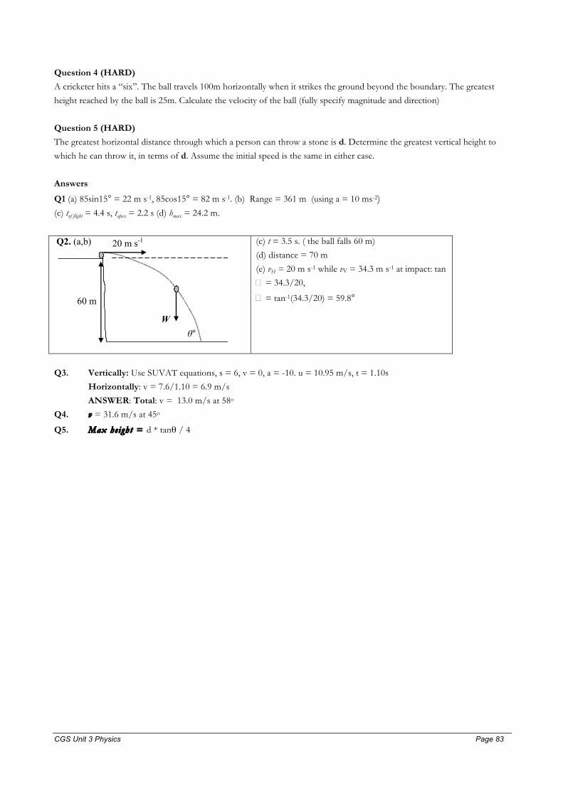
CGS Unit 3 Physics Page 83 Page 83
Question 4 (HARD)
A cricketer hits a “six”. The ball travels 100m horizontally when it strikes the ground beyond the boundary. The greatest
height reached by the ball is 25m. Calculate the velocity of the ball (fully specify magnitude and direction)
Question 5 (HARD)
The greatest horizontal distance through which a person can throw a stone is d. Determine the greatest vertical height to
which he can throw it, in terms of d. Assume the initial speed is the same in either case.
Answers
Q1 (a) 85sin15° = 22 m s-1, 85cos15° = 82 m s-1. (b) Range = 361 m (using a = 10 ms-2) (c) tof flight = 4.4 s, tapex = 2.2 s (d) hmax = 24.2 m.
Q2. (a,b) 20 m s-1
60 m
W θ°
(c) t = 3.5 s. ( the ball falls 60 m)
(d) distance = 70 m
(e) vH = 20 m s-1 while vV = 34.3 m s-1 at impact: tan
� = 34.3/20,
� = tan-1(34.3/20) = 59.8°
Q3. Vertically: Use SUVAT equations, s = 6, v = 0, a = -10. u = 10.95 m/s, t = 1.10s
Horizontally: v = 7.6/1.10 = 6.9 m/s
ANSWER: Total: v = 13.0 m/s at 58o
Q4. v = 31.6 m/s at 45o
Q5. Max he ight = d * tanθ / 4
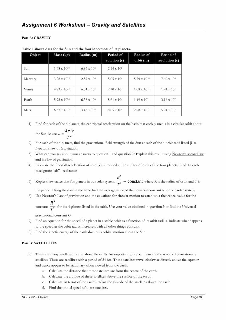
CGS Unit 3 Physics Page 84 Page 84
Assignment 6 Worksheet – Gravity and Satellites
Part A: GRAVITY
Table 1 shows data for the Sun and the four innermost of its planets.
Object Mass (kg) Radius (m) Period of
rotation (s)
Radius of
orbit (m)
Period of
revolution (s)
Sun 1.98 x 1030 6.95 x 10⁸ 2.14 x 10⁶
Mercury 3.28 x 10²³ 2.57 x 10⁶ 5.05 x 10⁶ 5.79 x 10¹⁰ 7.60 x 10⁶
Venus 4.83 x 1024 6.31 x 10⁶ 2.10 x 10⁷ 1.08 x 10¹¹ 1.94 x 10⁷
Earth 5.98 x 1024 6.38 x 10⁶ 8.61 x 10⁴ 1.49 x 10¹¹ 3.16 x 10⁷
Mars 6.37 x 10²³ 3.43 x 10⁶ 8.85 x 10⁴ 2.28 x 10¹¹ 5.94 x 10⁷
1) Find for each of the 4 planets, the centripetal acceleration on the basis that each planet is in a circular orbit about
the Sun, ie use 2
24Tra π
=
2) For each of the 4 planets, find the gravitational field strength of the Sun at each of the 4 orbit radii listed [Use
Newton’s law of Gravitation]
3) What can you say about your answers to question 1 and question 2? Explain this result using Newton’s second law
and his law of gravitation
4) Calculate the free-fall acceleration of an object dropped at the surface of each of the four planets listed. In each
case ignore “air” –resistance
5) Kepler’s law states that for planets in our solar system RT
3
2 = constant where R is the radius of orbit and T is
the period. Using the data in the table find the average value of the universal constant R for our solar system
6) Use Newton’s Law of gravitation and the equations for circular motion to establish a theoretical value for the
constant RT
3
2 for the 4 planets listed in the table. Use your value obtained in question 5 to find the Universal
gravitational constant G.
7) Find an equation for the speed of a planet in a stable orbit as a function of its orbit radius. Indicate what happens
to the speed as the orbit radius increases, with all other things constant.
8) Find the kinetic energy of the earth due to its orbital motion about the Sun.
Part B: SATELLITES
9) There are many satellites in orbit about the earth. An important group of them are the so-called geostationary
satellites. These are satellites with a period of 24 hrs. These satellites travel clockwise directly above the equator
and hence appear to be stationary when viewed from the earth.
a. Calculate the distance that these satellites are from the centre of the earth
b. Calculate the altitude of these satellites above the surface of the earth.
c. Calculate, in terms of the earth’s radius the altitude of the satellites above the earth.
d. Find the orbital speed of these satellites.

CGS Unit 3 Physics Page 85 Page 85
e. Could a satellite be positioned directly above Melbourne? Why not?
10) Calculate the gravitational field strength and hence the free fall acceleration of the space craft towards the centre of
the earth when in a stable orbit of altitude 300 km.
11) Consider a 70 kg astronaut within the space shuttle.
a. What is the mass of the astronaut?
b. What is the actual weight of the astronaut?
c. Explain why the astronaut feels as though he or she is weightless?
12) When a satellite is launched both the kinetic energy and gravitational potential energy are increased as the satellite
is placed in a stable orbit. Consider a 1500 kg satellite that is to be positioned in a stable orbit at an altitude of 3
earth radii.
Gravitational Field Strength
0.00
1.00
2.00
3.00
4.00
5.00
6.00
7.00
8.00
9.00
10.00
11.00
0 1 2 3 4 5 6 7 8 9
distance in units of earth radius
g (N
/kg)
a. Calculate the increase in potential energy as the satellite is launched from the earth and positioned into
the stable orbit. (Use a series of trapeziums to estimate the work done per kilogram from a plot of the
gravitational field strength (N kg-1) versus radial distance (m) shown above. b. Find the kinetic energy of the satellite when in a stable orbit.
c. If the satellite were to be further lifted to new orbit 6 earth radii from the surface of the earth, calculate
the increase in gravitational potential energy. (Note this is approximately the distance required to obtain a
geostationary orbit.)
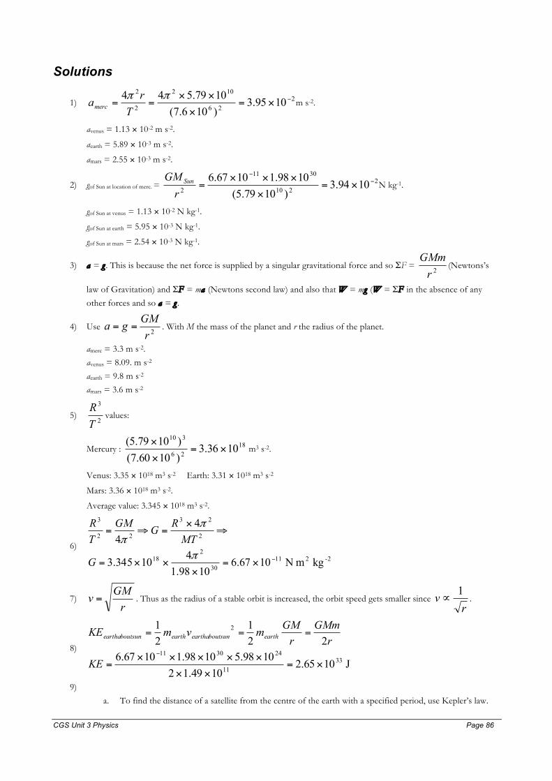
CGS Unit 3 Physics Page 86 Page 86
Solutions
1) 226
102
2
2
1095.3)106.7(1079.544 −×=
×
××==
ππTramerc m s-2.
avenus = 1.13 × 10⁻² m s-2.
aearth = 5.89 × 10⁻³ m s-2.
amars = 2.55 × 10⁻³ m s-2.
2) gof Sun at location of merc. = 2210
3011
2 1094.3)1079.5(1098.11067.6 −
−
×=×
×××=
rGM Sun N kg-1.
gof Sun at venus = 1.13 × 10⁻² N kg-1.
gof Sun at earth = 5.95 × 10⁻³ N kg-1.
gof Sun at mars = 2.54 × 10⁻³ N kg-1.
3) a = g . This is because the net force is supplied by a singular gravitational force and so ΣF = 2r
GMm(Newtons’s
law of Gravitation) and ΣF = ma (Newtons second law) and also that W = mg (W = ΣF in the absence of any
other forces and so a = g .
4) Use 2r
GMga == . With M the mass of the planet and r the radius of the planet.
amerc = 3.3 m s-2.
avenus = 8.09. m s-2
aearth = 9.8 m s-2
amars = 3.6 m s-2
5) 2
3
TR
values:
Mercury : 1826
310
1036.3)1060.7()1079.5(
×=×
× m3 s-2.
Venus: 3.35 × 10¹⁸ m3 s-2 Earth: 3.31 × 10¹⁸ m3 s-2
Mars: 3.36 × 10¹⁸ m3 s-2.
Average value: 3.345 × 10¹⁸ m3 s-2.
6) 2-211
30
218
2
23
22
3
kg m N 1067.61098.1
410345.3
44
−×=×
××=
⇒×
=⇒=
π
ππ
G
MTRGGM
TR
7) rGMv = . Thus as the radius of a stable orbit is increased, the orbit speed gets smaller since
rv 1∝ .
8)
J1065.21049.12
1098.51098.11067.622
121
3311
243011
2
×=××
×××××=
===
−
KE
rGMm
rGMmvmKE earthsunearthaboutearthsunearthabout
9)
a. To find the distance of a satellite from the centre of the earth with a specified period, use Kepler’s law.

CGS Unit 3 Physics Page 87 Page 87
32
224113
2
2
22
3
4)606024(1098.51067.6
44 πππ××××××
=⇒=⇒=−
RGMTRGMTR
R = 4.225 × 10⁷ m = 42,250 kilometre.
b. The altitude, A is the distance above the surface of the planet. We subtract off the radius of the planet
from the above to get the altitude of the satellite. A = R - re = 4.225 × 10⁷ – 6.38 × 106 = 3.587 × 10⁷ m.
c. To find how many earth radii the altitude is find the fraction: 6.51038.610587.36
7
=×
×=
erA
. Hence
geostationary satellites are 5.6 earth radii above the surface of the planet.
d. Use 305610225.4
1098.5106.67
2411
=×
×××==
−
rGMv m s-1 = 3.06 km s-1.
e. The centre of the minor circle that is the latitude on which Melbourne lies is not the centre of the earth
towards which all satellites must accelerate. This is because the net force acting on the satellite is the
gravitational force which is directed towards the centre of the earth not the centre of the minor circle.
10) g = 8.94 N kg-1 300 km above the surface of the earth.
11) a. m = 70 kg
b. W =70×8.94 = 626 N down.
c. Because the astronaut is in free-fall as well as the satellite, normal contact force acting on the astronaut within the satellite = 0 N.
12)
a. Use the trapezium rule to approximate the area with three trapezia from re to 4re. The area is equal to
ΔPE/mpayload. ΔPE = 1500× 6.38×106[2612.009.145.2
280.9
+++ ] = 8.37 × 10¹⁰ J.
b. The kinetic energy of the satellite when in a stable orbit is
KE = 6
2411
1038.64215001098.51067.6
2 ×××
××××=
−
rGMm
J = 1.17 × 10¹⁰ J.
c. In this question we want to calculate the ΔPE when the satellite is lifted from 4re to 7re. The actual area is
given by: ∫−=Δe
e
r
r
drrGMmPE
7
42
= area under graph = 1.00 × 10¹⁰ J. In Year 12 Physics you would use
the trapezium rule to estimate the area. As an extension, the minus sign is at the front of the integral
because the work done = ΔKE which is = -ΔPE.

CGS Unit 3 Physics Page 88 Page 88
Assignment 7 Worksheet – Materials and Structures
1. A steel rod with spring constant of 4 × 10⁶ N m-1 is subject to a tensile force of 8000 N. Calculate the extension of the rod.
2. Calculate the tensile stress produced in steel cables with a radius of 5.0 mm supports a force of 8000 N.
3. A 20 cm long steel rod undergoes 0.127 mm extension when subject to 10 kN of tensile force. Calculate the strain in the rod.
4. The Young’s Modulus for a particular grade of steel is 2 x 10¹¹ Pa. A solid steel column has length 5 m and radius 4 cm. Four of these columns are to be used in a building to support a total load of 4 x 10⁵ N. What will be the decrease in length of each column?
The data for the human bone is: • Tensile strength = 1.2 x 10⁸ Pa • Compressive strength = 1.7 x 10⁸ Pa • Young’s modulus = 1.6 x 10¹⁰ Pa • Elastic limit = 1 x 10⁸ Pa
5. The human femur has an average cross sectional area of 3.0 cm2 and an unloaded length of 40 cm.
a. What is the maximum compressive force that this bone can withstand before fracture? b. What is the maximum extension that the femur can tolerate before fracturing?
6. Determine the tension in the each of the two ropes.
5.0 kg mass take g = 10 N kg-1
20°
40°
7. Consider a 50 kg painter standing on a 15 kg plank. The plank is supported by two ladders, each which exert an
upward reaction force on plank. The painter is 1.0 m from ladder A and the two ladders are separated by 4.0 m
a. Draw a vector force diagram to illustrate all forces acting on the plank.
b. State the two conditions that must be met in order that the plank is in equilibrium. c. Calculate the size of the force that ladder A exerts on the plank and the force that ladder B exerts on the
plank.
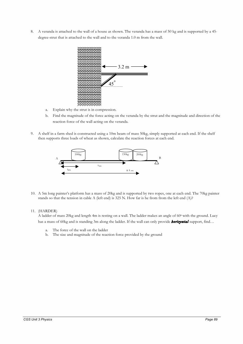
CGS Unit 3 Physics Page 89 Page 89
8. A veranda is attached to the wall of a house as shown. The veranda has a mass of 50 kg and is supported by a 45-
degree-strut that is attached to the wall and to the veranda 1.0 m from the wall.
3.2 m
45°
a. Explain why the strut is in compression.
b. Find the magnitude of the force acting on the veranda by the strut and the magnitude and direction of the
reaction force of the wall acting on the veranda.
9. A shelf in a farm shed is constructed using a 10m beam of mass 50kg, simply supported at each end. If the shelf then supports three loads of wheat as shown, calculate the reaction forces at each end.
10. A 5m long painter’s platform has a mass of 20kg and is supported by two ropes, one at each end. The 70kg painter stands so that the tension in cable A (left end) is 325 N. How far is he from from the left end (A)?
11. (HARDER) A ladder of mass 20kg and length 4m is resting on a wall. The ladder makes an angle of 60o with the ground. Lucy
has a mass of 60kg and is standing 3m along the ladder. If the wall can only provide hor izonta l support, find…
a. The force of the wall on the ladder b. The size and magnitude of the reaction force provided by the ground
100kg 200kg 150kg
3m 8.5 m 7m
A B
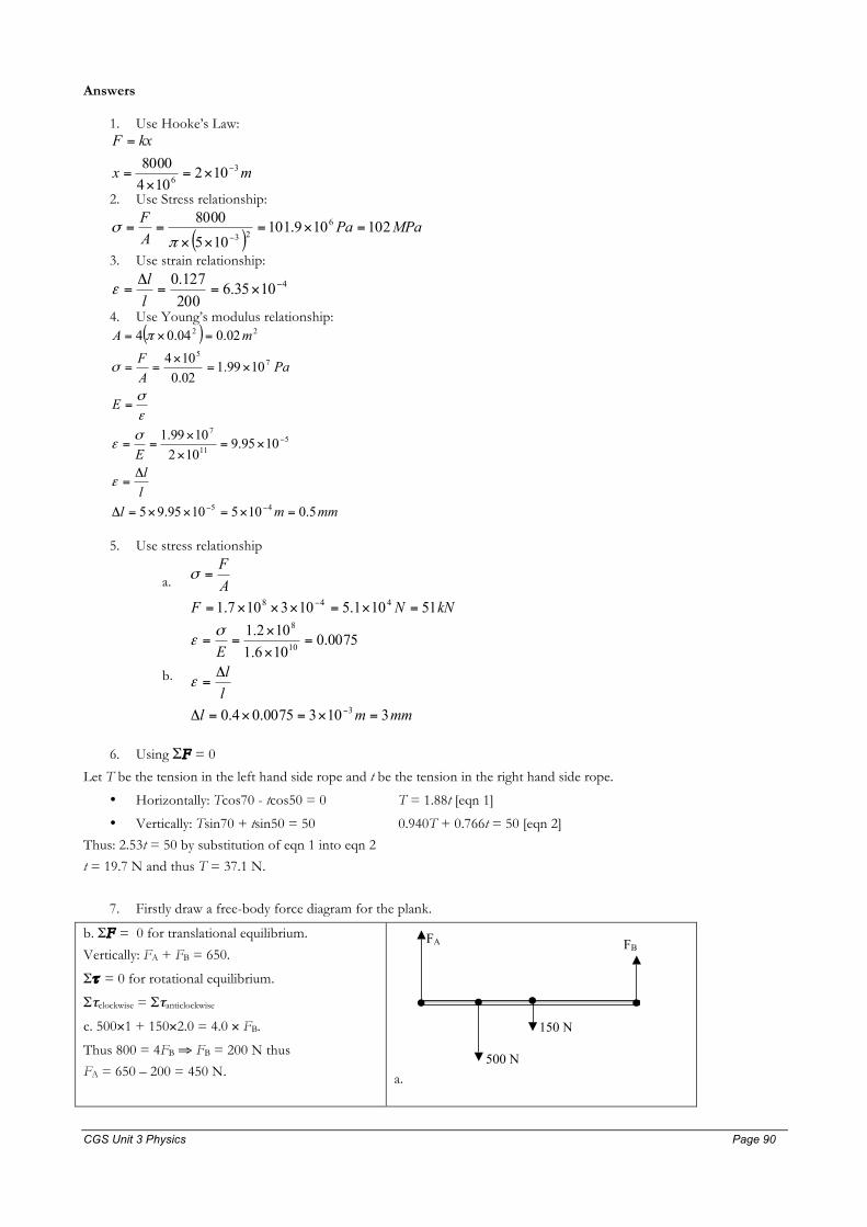
CGS Unit 3 Physics Page 90 Page 90
Answers
1. Use Hooke’s Law:
mx
kxF
36 102
1048000 −×=×
=
=
2. Use Stress relationship:
( )MPaPa
AF 102109.101
1058000 6
23=×=
××==
−πσ
3. Use strain relationship:
41035.6200127.0 −×==
Δ=ll
ε
4. Use Young’s modulus relationship: ( )
mmmlllE
E
PaAF
mA
5.01051095.95
1095.91021099.1
1099.102.0104
02.004.04
45
511
7
75
22
=×=××=Δ
Δ=
×=×
×==
=
×=×
==
=×=
−−
−
ε
σε
εσ
σ
π
5. Use stress relationship
a.
kNNFAF
51101.5103107.1 448 =×=×××=
=
−
σ
b.
mmmlllE
31030075.04.0
0075.0106.1102.1
3
10
8
=×=×=Δ
Δ=
=×
×==
−
ε
σε
6. Using ΣF = 0
Let T be the tension in the left hand side rope and t be the tension in the right hand side rope.
• Horizontally: Tcos70 - tcos50 = 0 T = 1.88t [eqn 1]
• Vertically: Tsin70 + tsin50 = 50 0.940T + 0.766t = 50 [eqn 2]
Thus: 2.53t = 50 by substitution of eqn 1 into eqn 2
t = 19.7 N and thus T = 37.1 N.
7. Firstly draw a free-body force diagram for the plank.
b. ΣF = 0 for translational equilibrium.
Vertically: FA + FB = 650.
Στ = 0 for rotational equilibrium.
Στclockwise = Στanticlockwise
c. 500×1 + 150×2.0 = 4.0 × FB.
Thus 800 = 4FB ⇒ FB = 200 N thus
FA = 650 – 200 = 450 N.
a.
FA FB
150 N
500 N
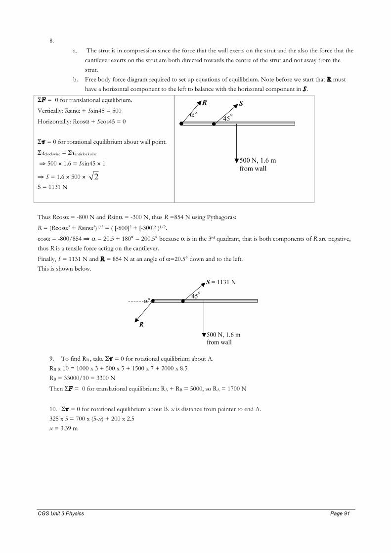
CGS Unit 3 Physics Page 91 Page 91
8.
a. The strut is in compression since the force that the wall exerts on the strut and the also the force that the
cantilever exerts on the strut are both directed towards the centre of the strut and not away from the
strut.
b. Free body force diagram required to set up equations of equilibrium. Note before we start that R must
have a horizontal component to the left to balance with the horizontal component in S .
ΣF = 0 for translational equilibrium.
Vertically: Rsinα + Ssin45 = 500
Horizontally: Rcosα + Scos45 = 0
Στ = 0 for rotational equilibrium about wall point.
Στclockwise = Στanticlockwise
⇒ 500 × 1.6 = Ssin45 × 1
⇒ S = 1.6 × 500 × 2
S = 1131 N
500 N, 1.6 m from wall
S
45°
R
α°
Thus Rcosα = -800 N and Rsinα = -300 N, thus R =854 N using Pythagoras:
R = (Rcosα2 + Rsinα2)1/2 = ( [-800]2 + [-300]2 )1/2.
cosα = -800/854 ⇒ α = 20.5 + 180° = 200.5° because α is in the 3rd quadrant, that is both components of R are negative,
thus R is a tensile force acting on the cantilever.
Finally, S = 1131 N and R = 854 N at an angle of α=20.5° down and to the left.
This is shown below.
500 N, 1.6 m from wall
S = 1131 N
45°
R
α°
9. To find RB , take Στ = 0 for rotational equilibrium about A.
RB x 10 = 1000 x 3 + 500 x 5 + 1500 x 7 + 2000 x 8.5
RB = 33000/10 = 3300 N
Then ΣF = 0 for translational equilibrium: RA + RB = 5000, so RA = 1700 N
10. Στ = 0 for rotational equilibrium about B. x is distance from painter to end A.
325 x 5 = 700 x (5-x) + 200 x 2.5
x = 3.39 m
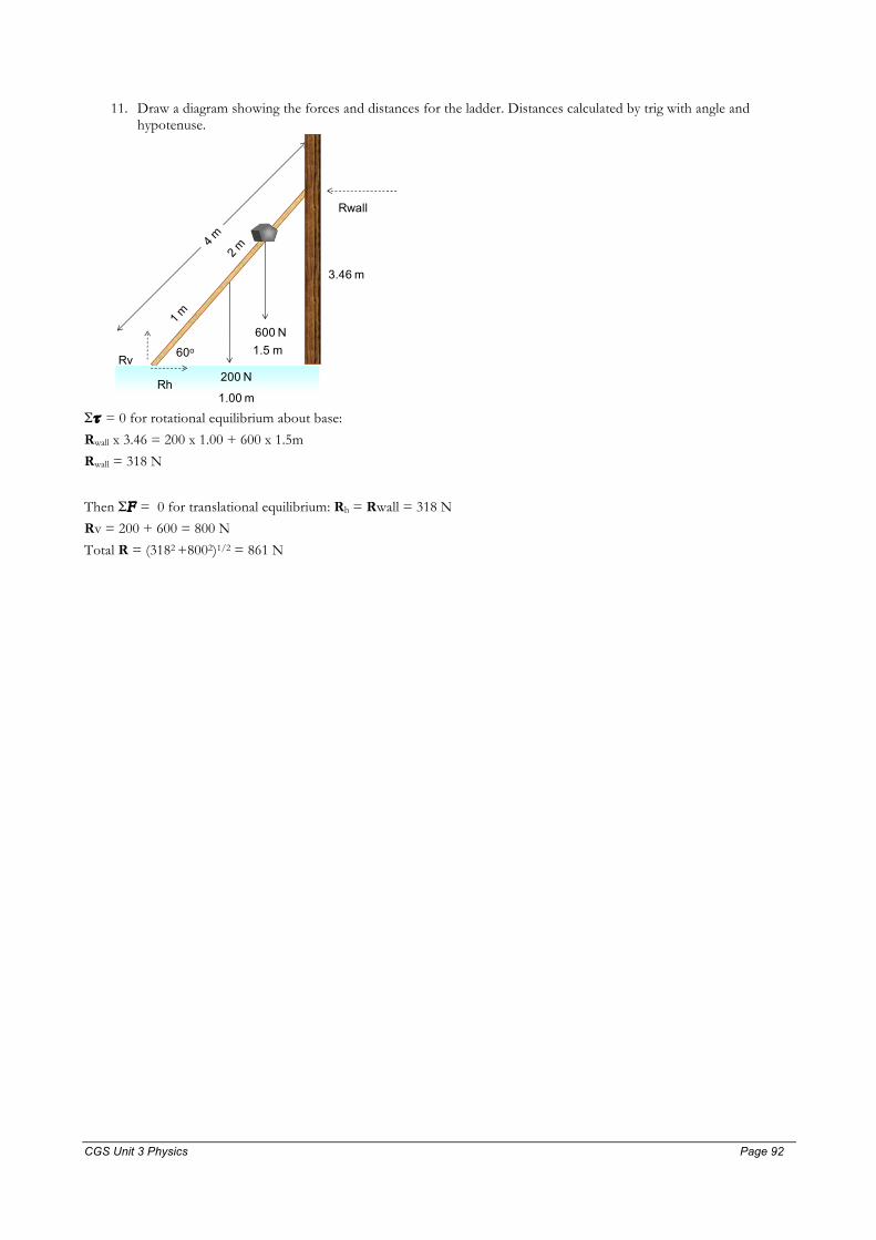
CGS Unit 3 Physics Page 92 Page 92
11. Draw a diagram showing the forces and distances for the ladder. Distances calculated by trig with angle and
hypotenuse.
Στ = 0 for rotational equilibrium about base:
Rwall x 3.46 = 200 x 1.00 + 600 x 1.5m
Rwall = 318 N
Then ΣF = 0 for translational equilibrium: Rh = Rwall = 318 N
Rv = 200 + 600 = 800 N
Total R = (3182 +8002)1/2 = 861 N
60o
200 N
600 N
Rwall
Rh
Rv
3.46 m
1.00 m
1.5 m

CGS Unit 3 Physics Page 93 Page 93
ASSIGNMENT 1- Chapter 4 Electronics
Topic Problems
Revision Worksheet – DC Circuits (distributed end of Term 4, 2010) (Reprinted Handbook p.55)
Circuit Analysis 100.1 – 101.6
Transducers 101.7 – 102.10 (ignore 9a)
Diodes 102.11 – 103.12
Amplifiers 103.14 – 103.17
ASSIGNMENT 2 – Chapter 5 Introductory Photonics
Topic Problems
Photonics Transducers Basic: 124.1 – 124.4, 125.6 – 126.15, Extension: 124.5, 126.16, 126.17
Modulation 126.20 – 126.21
ASSIGNMENT 3 – Chapter 1 Forces in Action
Topic Problems
Unit 2 Movement Revision Worksheet (Handbook p.64)
Unit 2 Forces Revision Worksheet (Handbook p.68)
Kinematics 21.1 – 22.3
Newton’s Laws 22.4 – 22.10
Applying Newton’s 2nd Law 22.11 – 23.17
ASSIGNMENT 4 – Chapter 2 Momentum, Impulse, Collisions & Energy
Topic Problems
Collisions Worksheets 1, 2 & 3 (Handbook p.72)
Momentum and Impulse 23.18 – 24.22, 42.2
Conservation of Momentum Basic: 42.3 – 43.6 Extension: 43.7
Work 43.8, 43.9
Springs 43.10 – 44.16
Collisions Basic: 44.17 – 45.23 Extension: 45.24
ASSIGNMENT 5 – Chapter 3 Projectile Motion
Topic Problems
Projectile Motion Worksheet (Handbook p.79)
Projectile Motion 78.1, 78.2, 78.4, 78.7 – 79.12, 79.14 – 80.19
ASSIGNMENT 6 – Chapter 3 Circular Motion, Gravity and Satellites
Topic Problems
Gravity Worksheet (Handbook p.81)
Circular Motion 80.20 – 80.28, 80.30 – 80.32 (80.29 is over specified and not consistent)
Gravity Basic: 81.33 – 81.38, Extension: 82.41, 82.42
Satellites 82.43 – 82.50
ASSIGNMENT 7 – Chapter 8 Investigating Structures
Topic Problems
Materials 210.1, 210.3 – 211.11, 212.14 – 212.18
Structures 212.19 – 213.22, 213.24 – 214.30