physics unit 2 revision (higher tier) · physics unit 3 revision (higher tier) x-rays x-rays are...
TRANSCRIPT

1
Physics Unit 3 Revision (Higher tier)
X-rays
X-rays are part of the electromagnetic spectrum, between gamma rays and UV
X-rays have a short wavelength (about the diameter of an atom) and can cause
ionisation. Ionisation is when the x-rays cause atoms to lose electrons, so when
an x-ray hits and electron orbiting a nucleus it gives it enough energy to become
free from the atom.
X-rays are used for medical imaging, in particular for imaging bones.
X-rays images can be recorded on photographic film or digitally (details below).
X-rays aren’t suitable for pregnancy scans are the radiation can cause
mutations to the baby which could cause abnormal growth or birth defects.
X-ray machine
produces the x-
rays
X-ray
beam
X-rays travel through
soft healthy tissues
but get absorbed by
metal and bone
When x-rays hit the photographic
film it turns black. The spots that
remain white are where the x-rays
got absorbed by the bones.
2
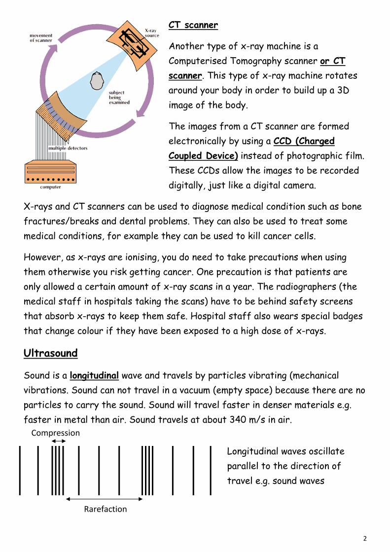
CT scanner
Another type of x-ray machine is a
Computerised Tomography scanner or CT
scanner. This type of x-ray machine rotates
around your body in order to build up a 3D
image of the body.
The images from a CT scanner are formed
electronically by using a CCD (Charged
Coupled Device) instead of photographic film.
These CCDs allow the images to be recorded
digitally, just like a digital camera.
X-rays and CT scanners can be used to diagnose medical condition such as bone
fractures/breaks and dental problems. They can also be used to treat some
medical conditions, for example they can be used to kill cancer cells.
However, as x-rays are ionising, you do need to take precautions when using
them otherwise you risk getting cancer. One precaution is that patients are
only allowed a certain amount of x-ray scans in a year. The radiographers (the
medical staff in hospitals taking the scans) have to be behind safety screens
that absorb x-rays to keep them safe. Hospital staff also wears special badges
that change colour if they have been exposed to a high dose of x-rays.
Ultrasound
Sound is a longitudinal wave and travels by particles vibrating (mechanical
vibrations. Sound can not travel in a vacuum (empty space) because there are no
particles to carry the sound. Sound will travel faster in denser materials e.g.
faster in metal than air. Sound travels at about 340 m/s in air.
Longitudinal waves oscillate
parallel to the direction of
travel e.g. sound waves
Compression
Rarefaction Rarefaction
3
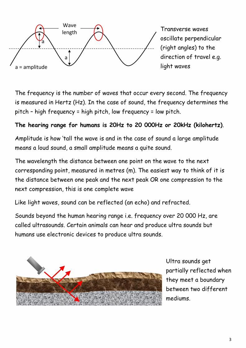
Transverse waves
oscillate perpendicular
(right angles) to the
direction of travel e.g.
light waves
The frequency is the number of waves that occur every second. The frequency
is measured in Hertz (Hz). In the case of sound, the frequency determines the
pitch – high frequency = high pitch, low frequency = low pitch.
The hearing range for humans is 20Hz to 20 000Hz or 20kHz (kilohertz).
Amplitude is how ‘tall the wave is and in the case of sound a large amplitude
means a loud sound, a small amplitude means a quite sound.
The wavelength the distance between one point on the wave to the next
corresponding point, measured in metres (m). The easiest way to think of it is
the distance between one peak and the next peak OR one compression to the
next compression, this is one complete wave
Like light waves, sound can be reflected (an echo) and refracted.
Sounds beyond the human hearing range i.e. frequency over 20 000 Hz, are
called ultrasounds. Certain animals can hear and produce ultra sounds but
humans use electronic devices to produce ultra sounds.
Ultra sounds get
partially reflected when
they meet a boundary
between two different
mediums.
Wave length
a = amplitude
a
a
4
An ultra sound pulse needs to travel to the
medium and back to the detector. So if a
detector indicated that the ultra sound
took 10 seconds to return. This must mean
that the object is 5 seconds away. If we
know how fast the ultra sound is travelling
then we can work out how far away it is.
Example question:
If it took 1 second for a bat to detect the ultrasound,
how far away is the prey? Sound travels at 340 m/s
Bat detected ultrasound after 1 second
Therefore the prey is 0.5 seconds away
Distance = speed x time
Distance = 340 x 0.5 = 170m
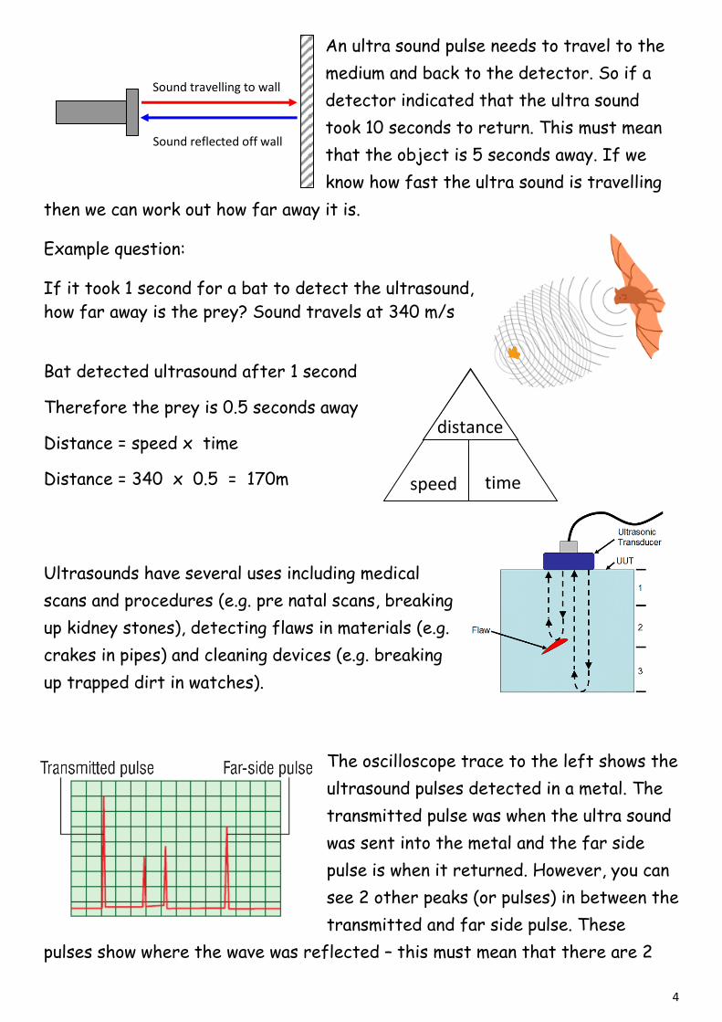
Ultrasounds have several uses including medical
scans and procedures (e.g. pre natal scans, breaking
up kidney stones), detecting flaws in materials (e.g.
crakes in pipes) and cleaning devices (e.g. breaking
up trapped dirt in watches).
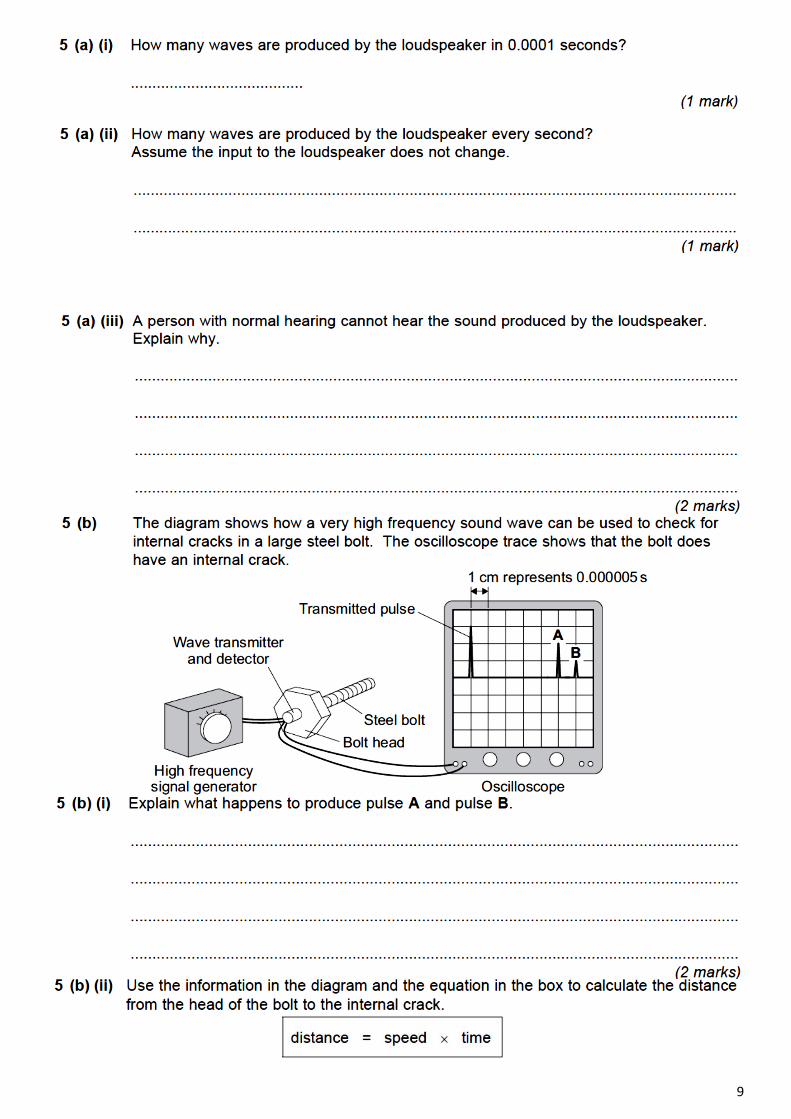
The oscilloscope trace to the left shows the
ultrasound pulses detected in a metal. The
transmitted pulse was when the ultra sound
was sent into the metal and the far side
pulse is when it returned. However, you can
see 2 other peaks (or pulses) in between the
transmitted and far side pulse. These
pulses show where the wave was reflected – this must mean that there are 2
Sound travelling to wall
Sound reflected off wall
distance
speed time

5
flaws in the metal. If one horizontal square represents 1 second then the first
flaw is showing up after 3s (3 squares) after the transmitted pulse. Remember
though, the sound travels there and back before it turns up on the oscilloscope.
This means that the ultrasound reached the flaw after 1.5 seconds (half of 3
seconds).
X- Rays CT Scanners Ultrasound
High radiation dose – can
cause cancer
Highest radiation does –
can cause cancer
No radiation – no cancer
caused
Ionising Ionising Non – ionising
Medium image quality –
doesn’t distinguish
between types of soft
tissues
Good image quality – can
distinguish between
types of soft tissues –
produces a 3D image
Bad images quality – only
one that is suitable for
baby scans as it is non-
ionising (no radiation)
Sample Question 1

6

7
Sample Question 2
(a) After a person is injured a doctor will sometimes ask for a photograph to be taken of the patient’s bone structure, e.g. in the case of a suspected broken arm.
(i) Which type of electromagnetic radiation would be used to take the photograph?
..................................................................................................................................... (1)
(ii) Describe the properties of this radiation which enable it to be used to photograph bone structure.
.....................................................................................................................................
.....................................................................................................................................
.....................................................................................................................................
..................................................................................................................................... (2)
(b) Explain fully why pregnant women should not normally have X-rays of the lower body.
...............................................................................................................................................
...............................................................................................................................................
...............................................................................................................................................
...............................................................................................................................................
............................................................................................................................................... (4)
(Total 7 marks)
Sample Question 3
The diagram shows an ultrasound monitor being used to scan a fetus.
8
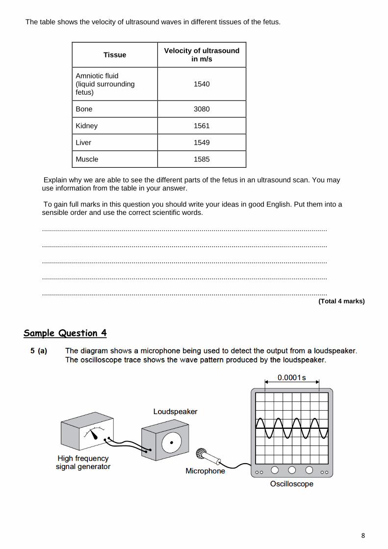
The table shows the velocity of ultrasound waves in different tissues of the fetus.
Tissue Velocity of ultrasound
in m/s
Amniotic fluid (liquid surrounding fetus)
1540
Bone 3080
Kidney 1561
Liver 1549
Muscle 1585
Explain why we are able to see the different parts of the fetus in an ultrasound scan. You may use information from the table in your answer.
To gain full marks in this question you should write your ideas in good English. Put them into a sensible order and use the correct scientific words.
...............................................................................................................................................
...............................................................................................................................................
...............................................................................................................................................
...............................................................................................................................................
............................................................................................................................................... (Total 4 marks)
Sample Question 4
9
10
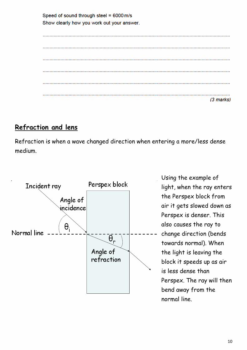
Refraction and lens
Refraction is when a wave changed direction when entering a more/less dense
medium.
Using the example of
light, when the ray enters
the Perspex block from
air it gets slowed down as
Perspex is denser. This
also causes the ray to
change direction (bends
towards normal). When
the light is leaving the
block it speeds up as air
is less dense than
Perspex. The ray will then
bend away from the
normal line.
11
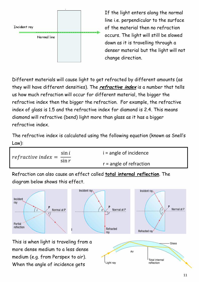
If the light enters along the normal
line i.e. perpendicular to the surface
of the material then no refraction
occurs. The light will still be slowed
down as it is travelling through a
denser material but the light will not
change direction.
Different materials will cause light to get refracted by different amounts (as
they will have different densities). The refractive index is a number that tells
us how much refraction will occur for different material, the bigger the
refractive index then the bigger the refraction. For example, the refractive
index of glass is 1.5 and the refractive index for diamond is 2.4. This means
diamond will refractive (bend) light more than glass as it has a bigger
refractive index.
The refractive index is calculated using the following equation (known as Snell’s
Law):
Refraction can also cause an effect called total internal reflection. The
diagram below shows this effect.
This is when light is traveling from a
more dense medium to a less dense
medium (e.g. from Perspex to air).
When the angle of incidence gets
i = angle of incidence
r = angle of refraction

12
increased to a certain amount the light will not leave the block, it will travel
along the boundary between both mediums (centre diagram). This angle, labeled
c, is the critical angle. If the angle of incidence is then further increased total
internal reflection can occur; this is when the light gets reflected within the
medium (e.g. in the right diagram above the medium is the semicircular block).
Total internal reflection happens in optical fibres which are used in endoscopes
to view the inside of your bodies.
Laser light is sometimes used in optical fibres and endoscopes too. It is used in
medicine for cutting tissue, sealing off leaking blood vessels (cauterizing), eye
surgery etc.
If you know the critical angle, then the refractive index can be calculated by
using
Lenses use the effect of refraction to form images and there are 2 types;
Concave, curved inwards or convex, curved outward
Convex (converging lens)
A converging lens focuses parallel light to one
point i.e. converges the light.
The point where the light gets focused is
called the focal point.
Concave (diverging lens)
A diverging lens makes the parallel light spread out i.e.
diverges the light
As a concave lens cause the light to spread out, this
means that they will never all meet at one real focal
point. But if we draw lines going straight back from the
diverged rays we can see that these imaginary rays do
all cross at a point. This is called the virtual focus. This
is the point that light appears to be focused at
Virtual
focus
13
On a ray diagram a converging lens is often shown as an
arrow shown as a double headed arrow (see right). A
diverging lens is diverging lens is represented as shown
in the diagram
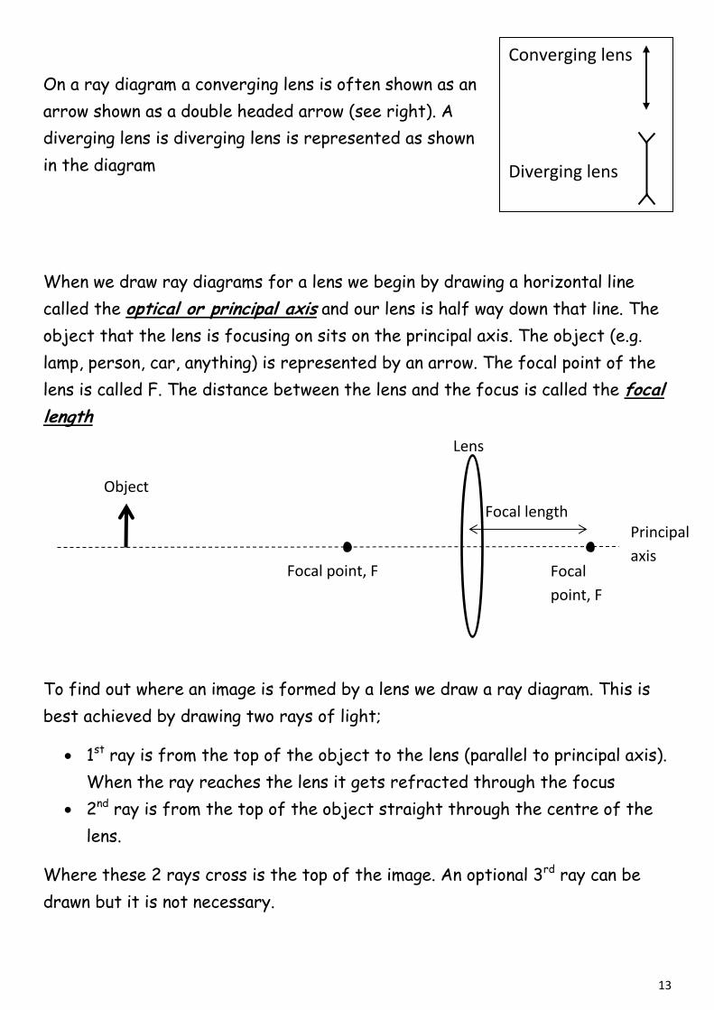
When we draw ray diagrams for a lens we begin by drawing a horizontal line
called the optical or principal axis and our lens is half way down that line. The
object that the lens is focusing on sits on the principal axis. The object (e.g.
lamp, person, car, anything) is represented by an arrow. The focal point of the
lens is called F. The distance between the lens and the focus is called the focal
length
To find out where an image is formed by a lens we draw a ray diagram. This is
best achieved by drawing two rays of light;
1st ray is from the top of the object to the lens (parallel to principal axis).
When the ray reaches the lens it gets refracted through the focus
2nd ray is from the top of the object straight through the centre of the
lens.
Where these 2 rays cross is the top of the image. An optional 3rd ray can be
drawn but it is not necessary.
Converging lens
Diverging lens
Focal point, F
Lens
Principal
axis
Object
Focal
point, F
Focal length
14
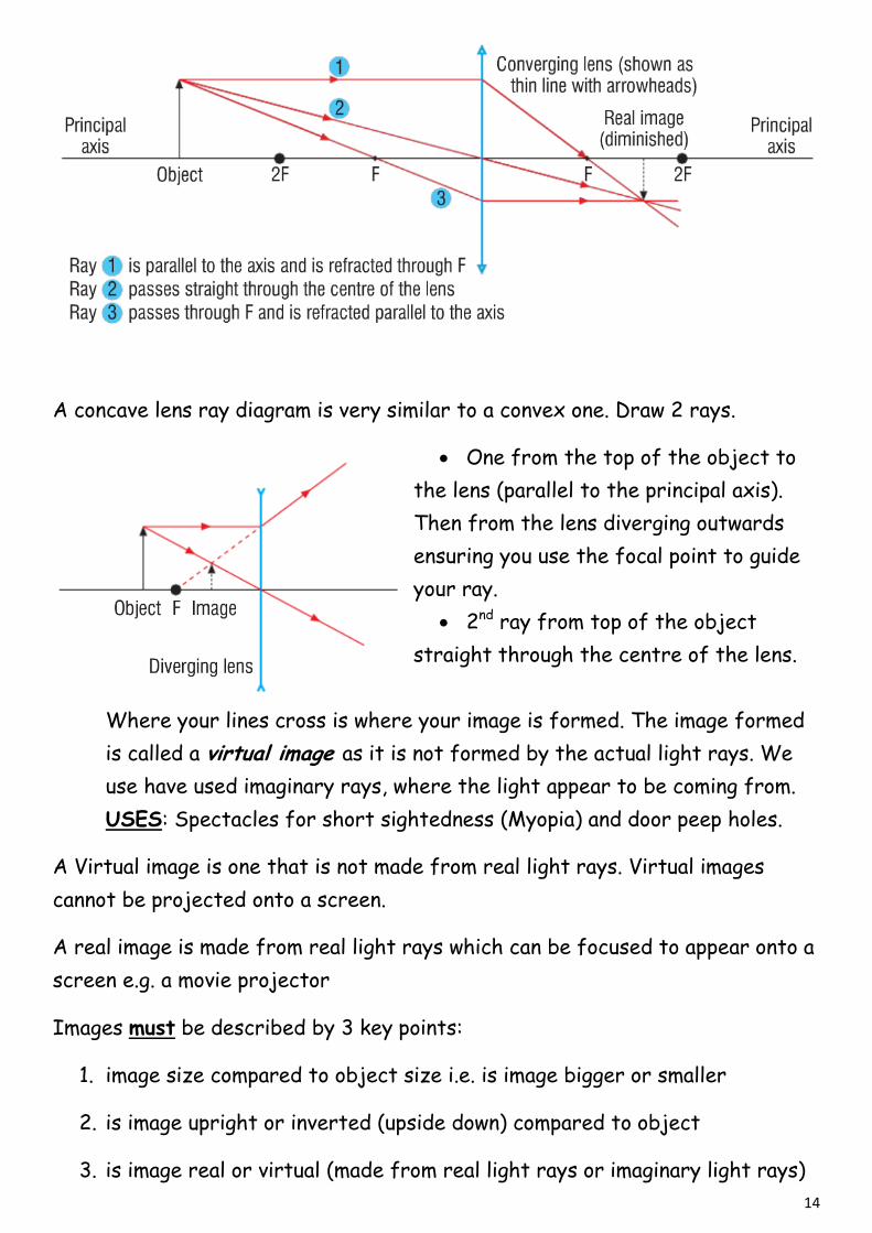
A concave lens ray diagram is very similar to a convex one. Draw 2 rays.
One from the top of the object to
the lens (parallel to the principal axis).
Then from the lens diverging outwards
ensuring you use the focal point to guide
your ray.
2nd ray from top of the object
straight through the centre of the lens.
Where your lines cross is where your image is formed. The image formed
is called a virtual image as it is not formed by the actual light rays. We
use have used imaginary rays, where the light appear to be coming from.
USES: Spectacles for short sightedness (Myopia) and door peep holes.
A Virtual image is one that is not made from real light rays. Virtual images
cannot be projected onto a screen.
A real image is made from real light rays which can be focused to appear onto a
screen e.g. a movie projector
Images must be described by 3 key points:
1. image size compared to object size i.e. is image bigger or smaller
2. is image upright or inverted (upside down) compared to object
3. is image real or virtual (made from real light rays or imaginary light rays)
15
Diverging lenses always produce the same type of image:
1. Virtual
2. upright
3. smaller
Some can images are bigger or smaller that the object. In order to work out
the amount of magnification we use this formula:
heightobject
heightimageionmagnificat
If the magnification is less than 1 then the image is smaller than the object.
If the magnification is more than 1 then the image is bigger than the object.
If the magnification is equal to 1 then the image and object are the same
height.
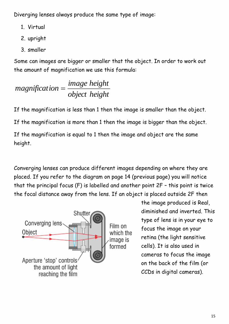
Converging lenses can produce different images depending on where they are
placed. If you refer to the diagram on page 14 (previous page) you will notice
that the principal focus (F) is labelled and another point 2F – this point is twice
the focal distance away from the lens. If an object is placed outside 2F then
the image produced is Real,
diminished and inverted. This
type of lens is in your eye to
focus the image on your
retina (the light sensitive
cells). It is also used in
cameras to focus the image
on the back of the film (or
CCDs in digital cameras).
16
If an object is placed between 2F and F then the image produced will be real,
inverted and magnified. A use for this is in
projectors.
If an object is placed at F then the rays of
light will never meet. This is used for spotlights.
If an object is placed between the principal
focus (F) and the lens then a virtual image can
be produced (see diagram). This image is
upright and magnified and a use for this is magnifying glasses.
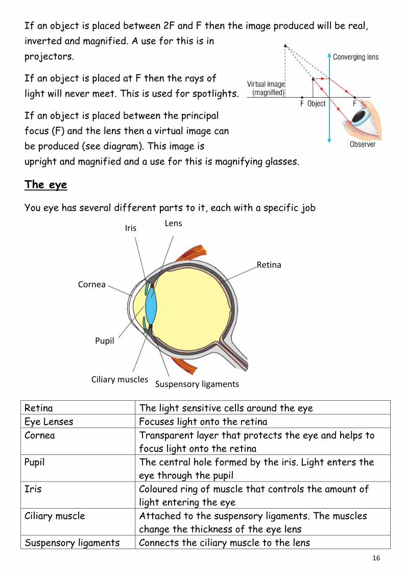
The eye
You eye has several different parts to it, each with a specific job
Retina The light sensitive cells around the eye
Eye Lenses Focuses light onto the retina
Cornea Transparent layer that protects the eye and helps to
focus light onto the retina
Pupil The central hole formed by the iris. Light enters the
eye through the pupil
Iris Coloured ring of muscle that controls the amount of
light entering the eye
Ciliary muscle Attached to the suspensory ligaments. The muscles
change the thickness of the eye lens
Suspensory ligaments Connects the ciliary muscle to the lens
Iris Lens
Retina
Cornea
Pupil
Suspensory ligaments Ciliary muscles
17
You eye has a huge range of vision being able to focus things close up (near
point which is about 25cm) and far away (far point is infinity). It can do this
because the ciliary muscles can change the shape of your lens which will change
your focal length. The roles of the eye and the camera can be compared
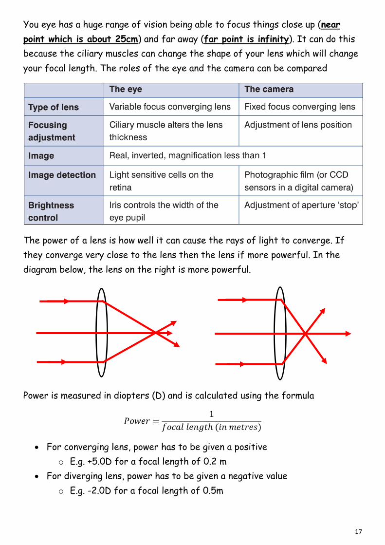
The power of a lens is how well it can cause the rays of light to converge. If
they converge very close to the lens then the lens if more powerful. In the
diagram below, the lens on the right is more powerful.
Power is measured in diopters (D) and is calculated using the formula
For converging lens, power has to be given a positive
o E.g. +5.0D for a focal length of 0.2 m
For diverging lens, power has to be given a negative value
o E.g. -2.0D for a focal length of 0.5m
18
The focal length of a lens depends on 2 factors
The refractive index of the lens material (bigger refractive index means
shorted focal length which means more powerful)
How curved the 2 sides of the lens are (the curvature of the lens)
o If it is less curved (thinner) it will have a bigger focal length (less
power) and more curved (thicker) it will have a smaller focal length
(more power)
So if you want a really thin lens in a pair of spectacles, then you will need to use
a material with a large refractive index
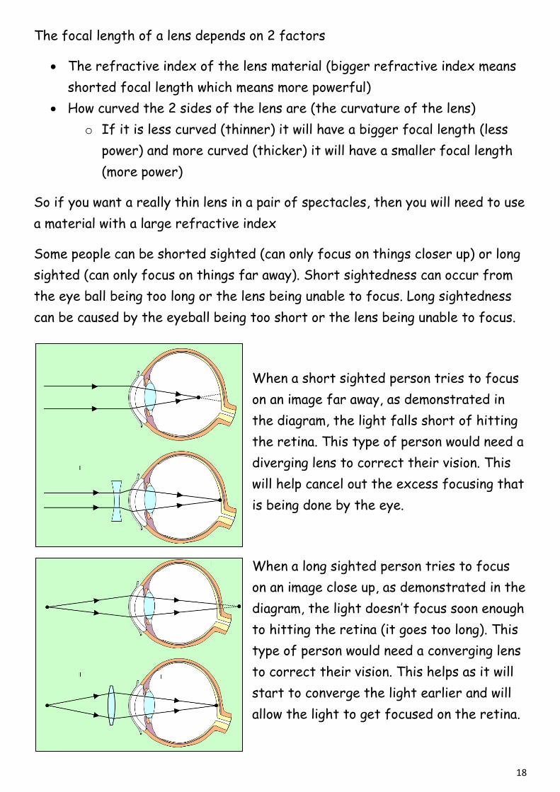
Some people can be shorted sighted (can only focus on things closer up) or long
sighted (can only focus on things far away). Short sightedness can occur from
the eye ball being too long or the lens being unable to focus. Long sightedness
can be caused by the eyeball being too short or the lens being unable to focus.
When a short sighted person tries to focus
on an image far away, as demonstrated in
the diagram, the light falls short of hitting
the retina. This type of person would need a
diverging lens to correct their vision. This
will help cancel out the excess focusing that
is being done by the eye.
When a long sighted person tries to focus
on an image close up, as demonstrated in the
diagram, the light doesn’t focus soon enough
to hitting the retina (it goes too long). This
type of person would need a converging lens
to correct their vision. This helps as it will
start to converge the light earlier and will
allow the light to get focused on the retina.

19
Sample Question 5
20
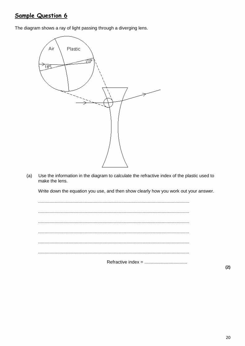
Sample Question 6
The diagram shows a ray of light passing through a diverging lens.
(a) Use the information in the diagram to calculate the refractive index of the plastic used to make the lens.
Write down the equation you use, and then show clearly how you work out your answer.
........................................................................................................................
........................................................................................................................
........................................................................................................................
........................................................................................................................
........................................................................................................................
........................................................................................................................
Refractive index = .................................. (2)

21
(b) The focal length of the lens is 5 cm. A student looking through the lens sees the image of a pin.
Complete the ray diagram below to show how the image of the pin is formed.
(3)
(Total 5 marks)
Sample Question 7
(a) The diagram shows a lens used as a magnifying glass. The position of the eye is shown and the size and position of an object standing at point O.
(i) What type of lens is shown in the diagram?
........................................................................................................................... (1)
(ii) Two points are marked as F. What are these points?
........................................................................................................................... (1)
(iii) What is the name of the straight line which goes through the point F, through the point L at the centre of the lens, and through the point F on the other side?
........................................................................................................................... (1)

22
(iv) On the diagram, use a ruler to construct accurately the position of the image. You should show how you construct your ray diagram and how light appears to come from this image to enter the eye.
(5)
(v) The image is virtual. What is a virtual image?
...........................................................................................................................
........................................................................................................................... (1)
(b) The lens shown in the diagram in part (a)(iv) can be used in a camera to produce a real image.
Explain why a real image must be produced in a camera and how the object and the lens are positioned to produce a real image which is smaller than the object.
Do not draw a ray diagram as part of your answer.
....................................................................................................................................
....................................................................................................................................
....................................................................................................................................
....................................................................................................................................
....................................................................................................................................
.................................................................................................................................... (3)
(Total 12 marks)
23
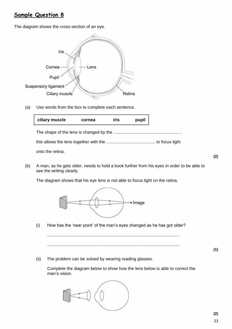
Sample Question 8
The diagram shows the cross-section of an eye.
(a) Use words from the box to complete each sentence.
ciliary muscle cornea iris pupil
The shape of the lens is changed by the ....................................................... ,
this allows the lens together with the ......................................... to focus light
onto the retina. (2)
(b) A man, as he gets older, needs to hold a book further from his eyes in order to be able to see the writing clearly.
The diagram shows that his eye lens is not able to focus light on the retina.
(i) How has the ‘near point’ of the man’s eyes changed as he has got older?
...............................................................................................................
............................................................................................................... (1)
(ii) The problem can be solved by wearing reading glasses.
Complete the diagram below to show how the lens below is able to correct the man’s vision.
(2)
24
(c) Give two similarities between an eye and a camera.
1 ............................................................................................................................................
2 ............................................................................................................................................ (2)
(Total 7 marks)
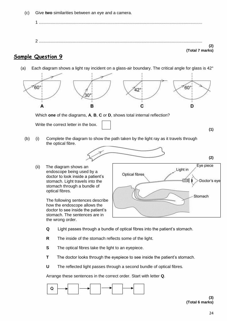
Sample Question 9
(a) Each diagram shows a light ray incident on a glass-air boundary. The critical angle for glass is 42°
Which one of the diagrams, A, B, C or D, shows total internal reflection?
Write the correct letter in the box. (1)
(b) (i) Complete the diagram to show the path taken by the light ray as it travels through the optical fibre.
(2)
(ii) The diagram shows an endoscope being used by a doctor to look inside a patient’s stomach. Light travels into the stomach through a bundle of optical fibres.
The following sentences describe how the endoscope allows the doctor to see inside the patient’s stomach. The sentences are in the wrong order.
Q Light passes through a bundle of optical fibres into the patient’s stomach.
R The inside of the stomach reflects some of the light.
S The optical fibres take the light to an eyepiece.
T The doctor looks through the eyepiece to see inside the patient’s stomach.
U The reflected light passes through a second bundle of optical fibres.
Arrange these sentences in the correct order. Start with letter Q.
(3)
(Total 6 marks)
25
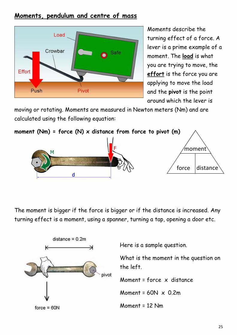
Moments, pendulum and centre of mass
Moments describe the
turning effect of a force. A
lever is a prime example of a
moment. The load is what
you are trying to move, the
effort is the force you are
applying to move the load
and the pivot is the point
around which the lever is
moving or rotating. Moments are measured in Newton meters (Nm) and are
calculated using the following equation:
moment (Nm) = force (N) x distance from force to pivot (m)
The moment is bigger if the force is bigger or if the distance is increased. Any
turning effect is a moment, using a spanner, turning a tap, opening a door etc.
Here is a sample question.
What is the moment in the question on
the left.
Moment = force x distance
Moment = 60N x 0.2m
Moment = 12 Nm
moment
force distance

26
The centre of mass (or
gravity) of an object is the
point where all the weight of
the object appears to act or
is concentrated. For an
object hanging freely, it will
come to rest with the centre
of mass below the point it is
suspended (or hanging) from.
The fact that an object, when suspended, will
come to rest with its centre of mass beneath
the suspension point is useful for pendulums. A
pendulum consists of a mass swinging back and
forth. The period of a pendulum is the time it
takes for one complete cycle of motion e.g. in
the diagram it would be the time it takes to go
from point A to point B and back to point A
(from A back to A). The period and the
frequency (the number of cycles every second
measured in Hertz, Hz) is related by the
following equation.
There is only one thing that will affect the period of a pendulum and that is the
length of the string
Longer string means a bigger period
Shorter string means a smaller period

27
To find the
centre of mass
of a symmetrical
body then it is
along the axis of
symmetry Where
the lines cross is
where the centre
of mass is. This
is why you can balance a ruler on the end of your finger if you position it
correctly i.e. so the centre of mass is on the tip of your finger. See saws also
use this principle.
For unsymmetrical or irregular shaped objects you can
find the centre of mass by freely suspending the
object from a point (see diagram on the left). If you
then use a ‘plumbline’ (a mass on a piece of string) you
can draw a line from the suspension point along the
plumbline. Now suspend the object from another point
and do the same thing. When the 2 lines cross is
where the centre of mass is.
Moments can also act in pairs like in see saws, there is a clockwise moment and
an anti clockwise moment. When the clockwise moment is the same as the anti
clockwise moment then the turning effects are balanced.
28
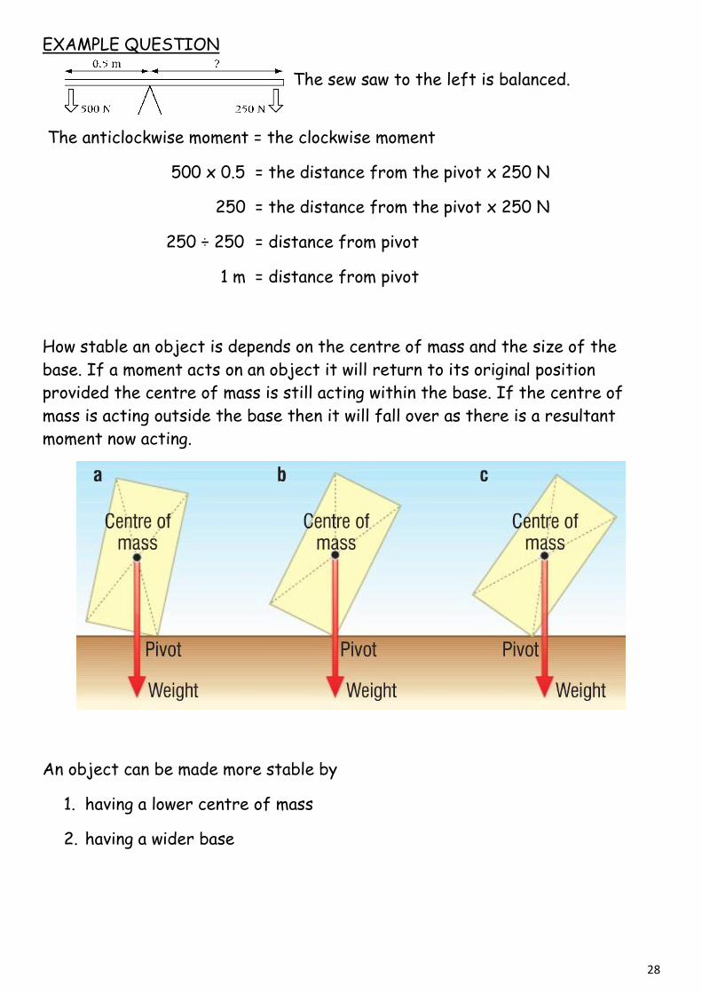
EXAMPLE QUESTION
The sew saw to the left is balanced.
The anticlockwise moment = the clockwise moment
500 x 0.5 = the distance from the pivot x 250 N
250 = the distance from the pivot x 250 N
250 ÷ 250 = distance from pivot
1 m = distance from pivot
How stable an object is depends on the centre of mass and the size of the
base. If a moment acts on an object it will return to its original position
provided the centre of mass is still acting within the base. If the centre of
mass is acting outside the base then it will fall over as there is a resultant
moment now acting.
An object can be made more stable by
1. having a lower centre of mass
2. having a wider base

29
Sample Question 10
30
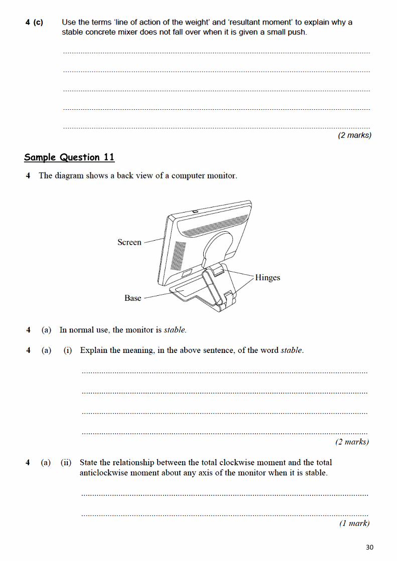
Sample Question 11
31
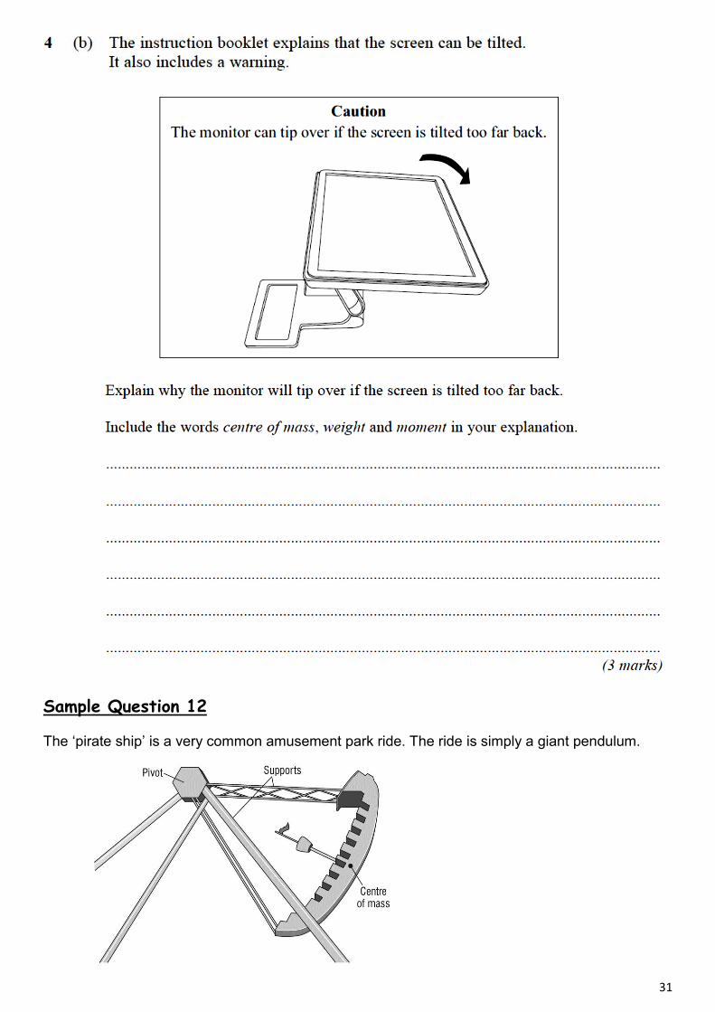
Sample Question 12
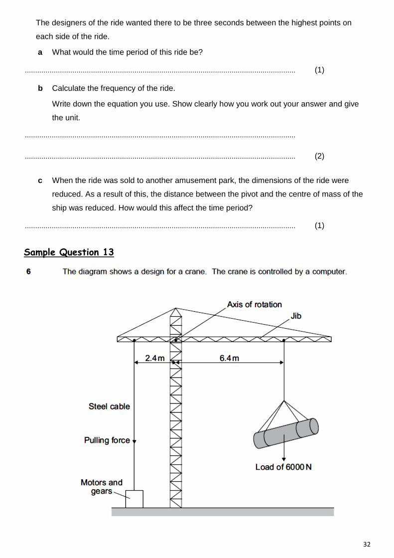
The ‘pirate ship’ is a very common amusement park ride. The ride is simply a giant pendulum.
32
The designers of the ride wanted there to be three seconds between the highest points on
each side of the ride.
a What would the time period of this ride be?
................................................................................................................................... (1)
b Calculate the frequency of the ride.
Write down the equation you use. Show clearly how you work out your answer and give
the unit.
...................................................................................................................................
................................................................................................................................... (2)
c When the ride was sold to another amusement park, the dimensions of the ride were
reduced. As a result of this, the distance between the pivot and the centre of mass of the
ship was reduced. How would this affect the time period?
................................................................................................................................... (1)
Sample Question 13

33
Sample Question 14
34
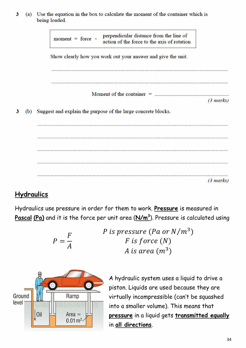
Hydraulics
Hydraulics use pressure in order for them to work. Pressure is measured in
Pascal (Pa) and it is the force per unit area (N/m3). Pressure is calculated using
⁄
A hydraulic system uses a liquid to drive a
piston. Liquids are used because they are
virtually incompressible (can’t be squashed
into a smaller volume). This means that
pressure in a liquid gets transmitted equally
in all directions.
35
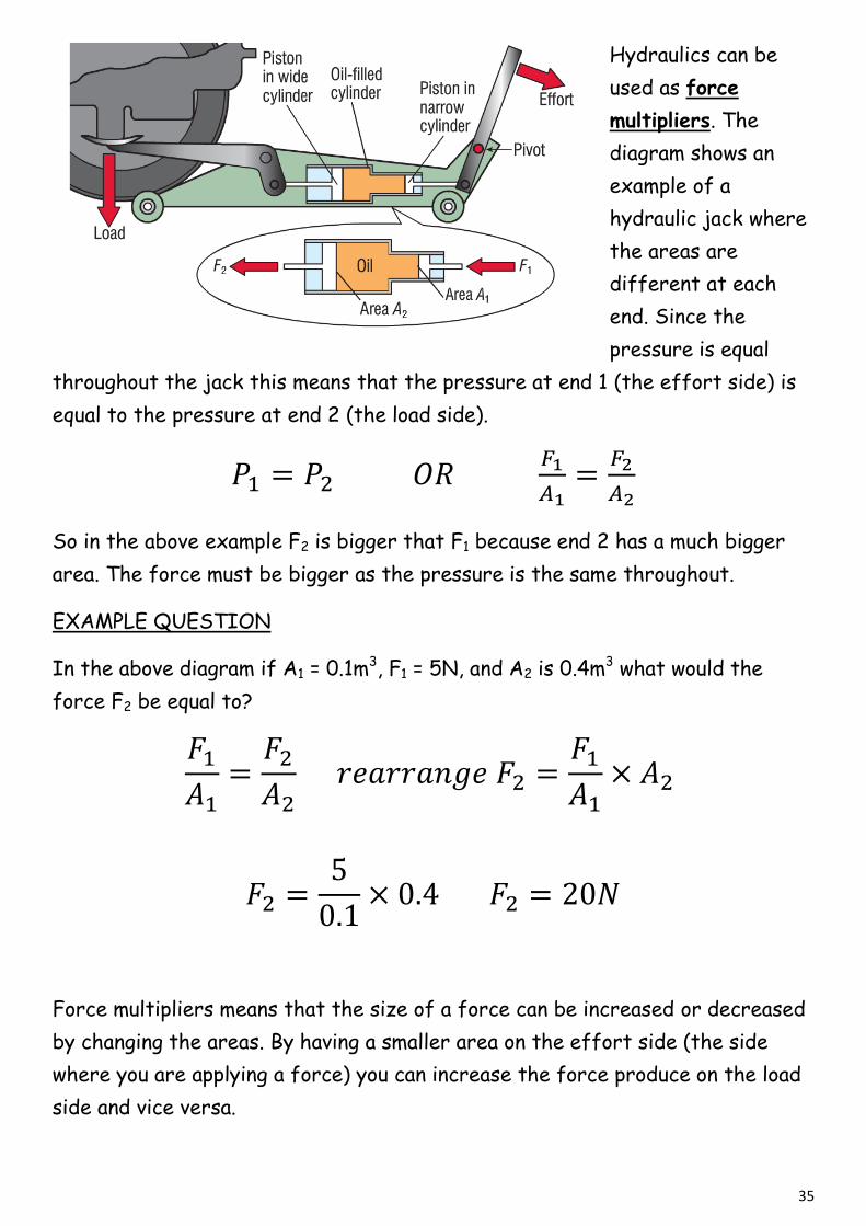
Hydraulics can be
used as force
multipliers. The
diagram shows an
example of a
hydraulic jack where
the areas are
different at each
end. Since the
pressure is equal
throughout the jack this means that the pressure at end 1 (the effort side) is
equal to the pressure at end 2 (the load side).
So in the above example F2 is bigger that F1 because end 2 has a much bigger
area. The force must be bigger as the pressure is the same throughout.
EXAMPLE QUESTION
In the above diagram if A1 = 0.1m3, F1 = 5N, and A2 is 0.4m3 what would the
force F2 be equal to?
Force multipliers means that the size of a force can be increased or decreased
by changing the areas. By having a smaller area on the effort side (the side
where you are applying a force) you can increase the force produce on the load
side and vice versa.
36
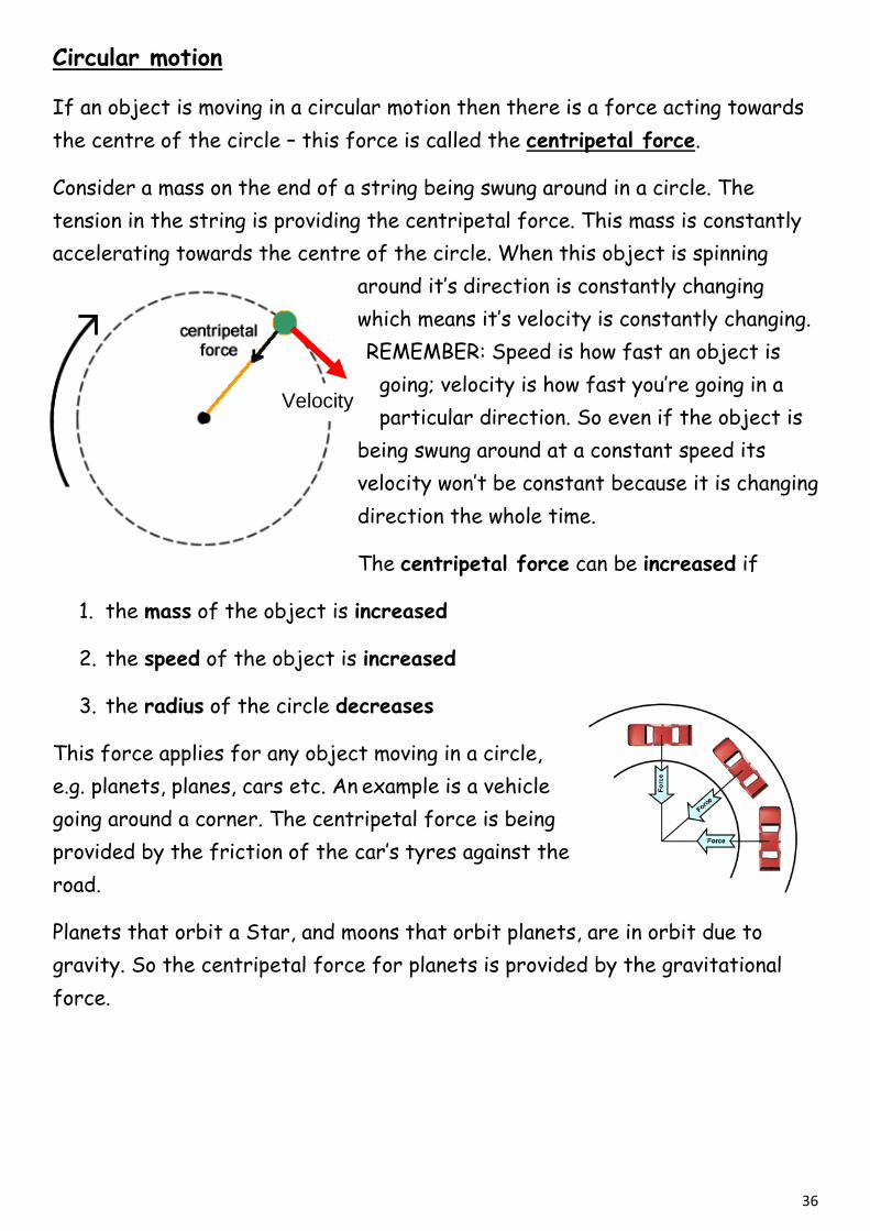
Circular motion
If an object is moving in a circular motion then there is a force acting towards
the centre of the circle – this force is called the centripetal force.
Consider a mass on the end of a string being swung around in a circle. The
tension in the string is providing the centripetal force. This mass is constantly
accelerating towards the centre of the circle. When this object is spinning
around it’s direction is constantly changing
which means it’s velocity is constantly changing.
REMEMBER: Speed is how fast an object is
going; velocity is how fast you’re going in a
particular direction. So even if the object is
being swung around at a constant speed its
velocity won’t be constant because it is changing
direction the whole time.
The centripetal force can be increased if
1. the mass of the object is increased
2. the speed of the object is increased
3. the radius of the circle decreases
This force applies for any object moving in a circle,
e.g. planets, planes, cars etc. An example is a vehicle
going around a corner. The centripetal force is being
provided by the friction of the car’s tyres against the
road.
Planets that orbit a Star, and moons that orbit planets, are in orbit due to
gravity. So the centripetal force for planets is provided by the gravitational
force.
Velocity
37
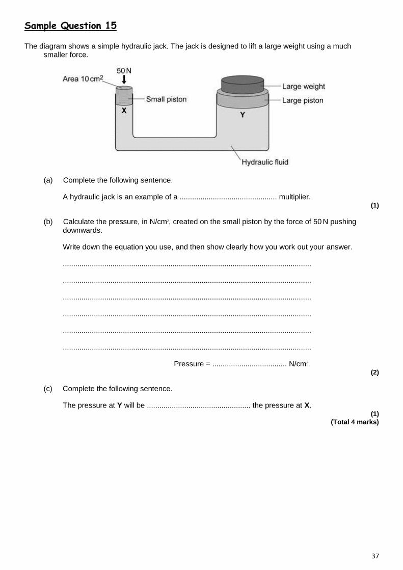
Sample Question 15
The diagram shows a simple hydraulic jack. The jack is designed to lift a large weight using a much smaller force.
(a) Complete the following sentence.
A hydraulic jack is an example of a ............................................... multiplier. (1)
(b) Calculate the pressure, in N/cm2, created on the small piston by the force of 50 N pushing downwards.
Write down the equation you use, and then show clearly how you work out your answer.
........................................................................................................................
........................................................................................................................
........................................................................................................................
........................................................................................................................
........................................................................................................................
........................................................................................................................
Pressure = .................................... N/cm2 (2)
(c) Complete the following sentence.
The pressure at Y will be .................................................. the pressure at X. (1)
(Total 4 marks)
38
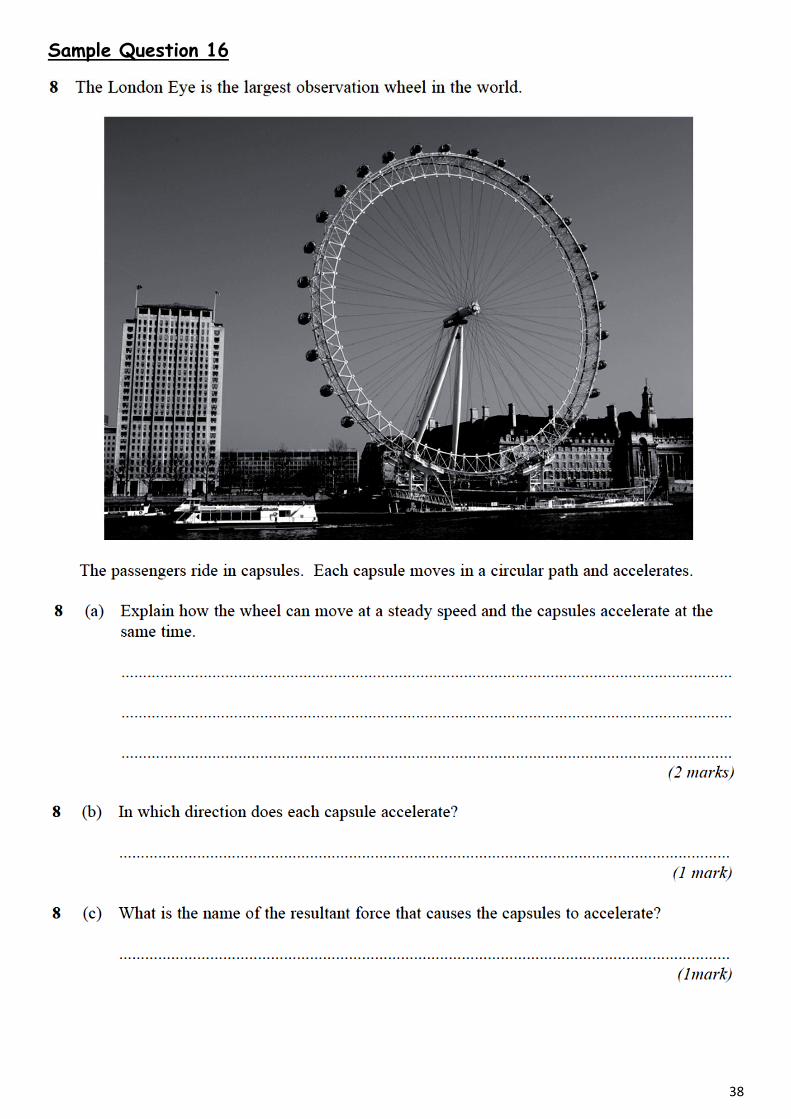
Sample Question 16

39
Sample Question 17
A satellite in stable Earth orbit moves at a constant speed in a circular orbit because there is a single force acting on it.
(i) What is the direction of this force?
..............................................................
.............................................................. (1)
(ii) What is the cause of this force?
..................................................................................................................................... (1)
(iii) What is the effect of this force on the velocity of the satellite?
..................................................................................................................................... (1)
(iv) In which of the orbits shown above would this force be bigger? Explain the reason for your answer. .....................................................................................................................................
..................................................................................................................................... (2)
(v) Explain why the kinetic energy of the satellite remains constant.
.....................................................................................................................................
.....................................................................................................................................
..................................................................................................................................... (2)
(Total 7 marks)
40
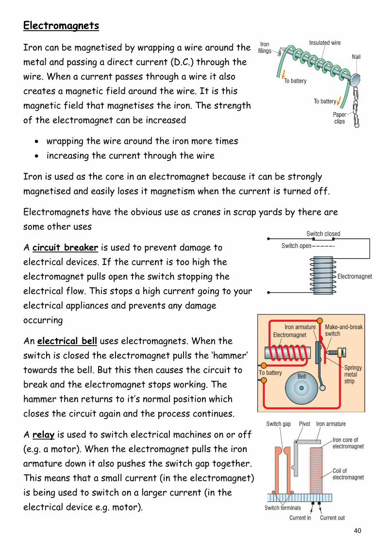
Electromagnets
Iron can be magnetised by wrapping a wire around the
metal and passing a direct current (D.C.) through the
wire. When a current passes through a wire it also
creates a magnetic field around the wire. It is this
magnetic field that magnetises the iron. The strength
of the electromagnet can be increased
wrapping the wire around the iron more times
increasing the current through the wire
Iron is used as the core in an electromagnet because it can be strongly
magnetised and easily loses it magnetism when the current is turned off.
Electromagnets have the obvious use as cranes in scrap yards by there are
some other uses
A circuit breaker is used to prevent damage to
electrical devices. If the current is too high the
electromagnet pulls open the switch stopping the
electrical flow. This stops a high current going to your
electrical appliances and prevents any damage
occurring
An electrical bell uses electromagnets. When the
switch is closed the electromagnet pulls the ‘hammer’
towards the bell. But this then causes the circuit to
break and the electromagnet stops working. The
hammer then returns to it’s normal position which
closes the circuit again and the process continues.
A relay is used to switch electrical machines on or off
(e.g. a motor). When the electromagnet pulls the iron
armature down it also pushes the switch gap together.
This means that a small current (in the electromagnet)
is being used to switch on a larger current (in the
electrical device e.g. motor).
41
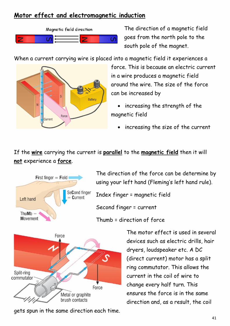
Motor effect and electromagnetic induction
The direction of a magnetic field
goes from the north pole to the
south pole of the magnet.
When a current carrying wire is placed into a magnetic field it experiences a
force. This is because an electric current
in a wire produces a magnetic field
around the wire. The size of the force
can be increased by
increasing the strength of the
magnetic field
increasing the size of the current
If the wire carrying the current is parallel to the magnetic field then it will
not experience a force.
The direction of the force can be determine by
using your left hand (Fleming’s left hand rule).
Index finger = magnetic field
Second finger = current
Thumb = direction of force
The motor effect is used in several
devices such as electric drills, hair
dryers, loudspeaker etc. A DC
(direct current) motor has a split
ring commutator. This allows the
current in the coil of wire to
change every half turn. This
ensures the force is in the same
direction and, as a result, the coil
gets spun in the same direction each time.

42
A similar effect, called electromagnet
induction, is when a changing magnetic field
induces (creates) a current in a wire and a
potential difference (voltage). When the
magnet is pushed into the coil the current goes
one way – positive current. When the magnet is
remove the current goes in the opposite
direction – negative current. The potential
difference also changes in this way.
Electrical generators produce
this alternating current (AC).
When a coil of wire is spun
within a magnet field (or a
magnet spinning inside a coil of
wire) the alternating current
and voltage is produced when
the wire ‘cuts through’ the
magnetic field lines. The slip
rings stop the wires from
getting tangled. The brushes
are in contact with the slip rings and take the alternating current from the coil
of wire and pass it into the circuit.
The size of the potential difference (voltage) produced can be increased by
increasing the speed of rotation
increasing the strength of the magnetic field
increasing the number of ‘turns’ on the wire
increasing the area of the coil
Coil of wire
43
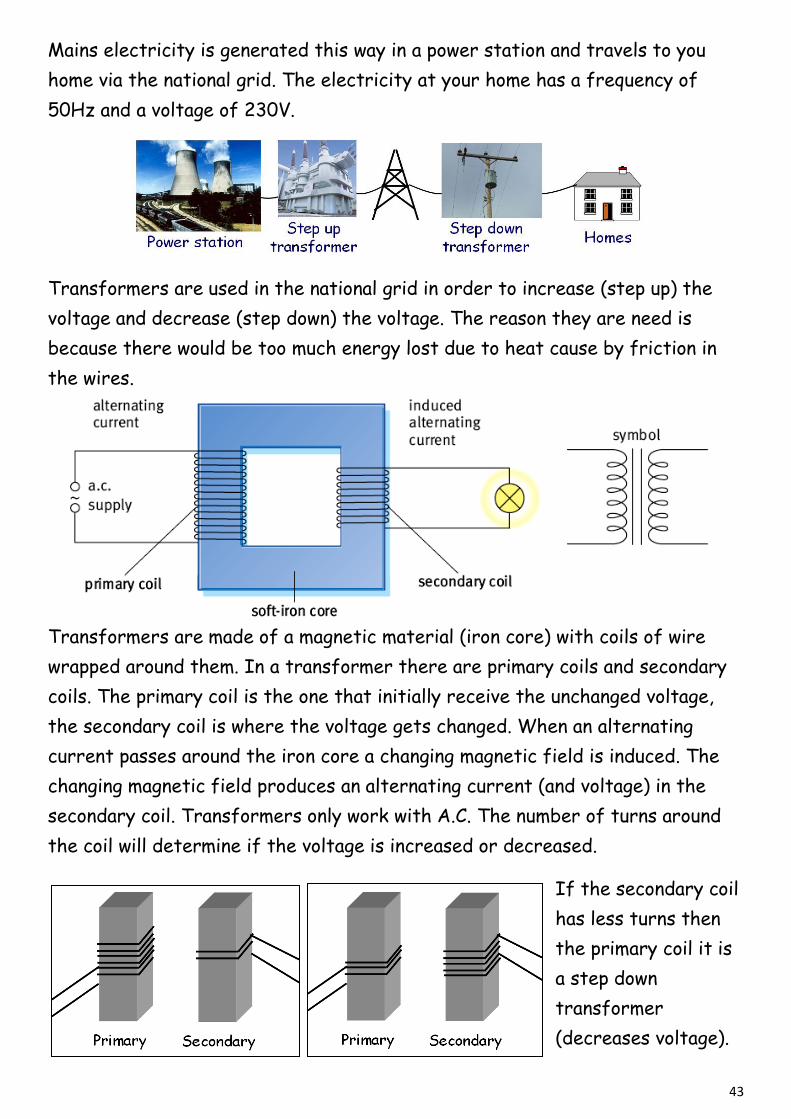
Mains electricity is generated this way in a power station and travels to you
home via the national grid. The electricity at your home has a frequency of
50Hz and a voltage of 230V.
Transformers are used in the national grid in order to increase (step up) the
voltage and decrease (step down) the voltage. The reason they are need is
because there would be too much energy lost due to heat cause by friction in
the wires.
Transformers are made of a magnetic material (iron core) with coils of wire
wrapped around them. In a transformer there are primary coils and secondary
coils. The primary coil is the one that initially receive the unchanged voltage,
the secondary coil is where the voltage gets changed. When an alternating
current passes around the iron core a changing magnetic field is induced. The
changing magnetic field produces an alternating current (and voltage) in the
secondary coil. Transformers only work with A.C. The number of turns around
the coil will determine if the voltage is increased or decreased.
If the secondary coil
has less turns then
the primary coil it is
a step down
transformer
(decreases voltage).

44
If the secondary coil has more turns then the primary coil it is a step up
transformer (increases voltage).
Transformers are governed by the following equation:
Power is equal to voltage times current (P = I × V) so if we assume that
transformers are 100% efficient then that means that
Transformers are commonly used in laptop and mobile phone charges but these
transformers are ‘switch-mode transformers’. They operate at a much higher
frequency, around 50 000Hz to 200 000Hz (50 kHz to
200 kHz) because they have a ferrite core rather than
an iron core. They are usually much lighter and smaller
than conventional transformers. A mobile phone charger
for example (see diagram) will change the frequency of
the mains electricity to a much higher frequency. The
voltage is then changed to a suitable level and finally the
A.C. is converted to D.C. to charge your phone. Switch
mode transformers are very efficient. Even when they
are switched on (i.e. plugged in) but no load is applied (i.e.
no phone/laptop connected) they use very little power.
45
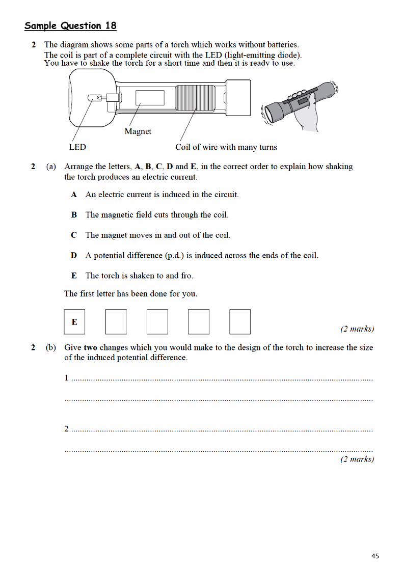
Sample Question 18
46
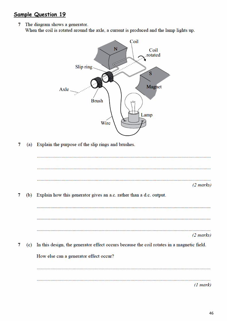
Sample Question 19
47
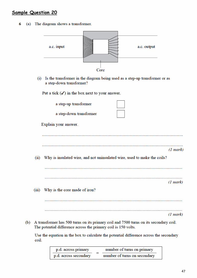
Sample Question 20
48
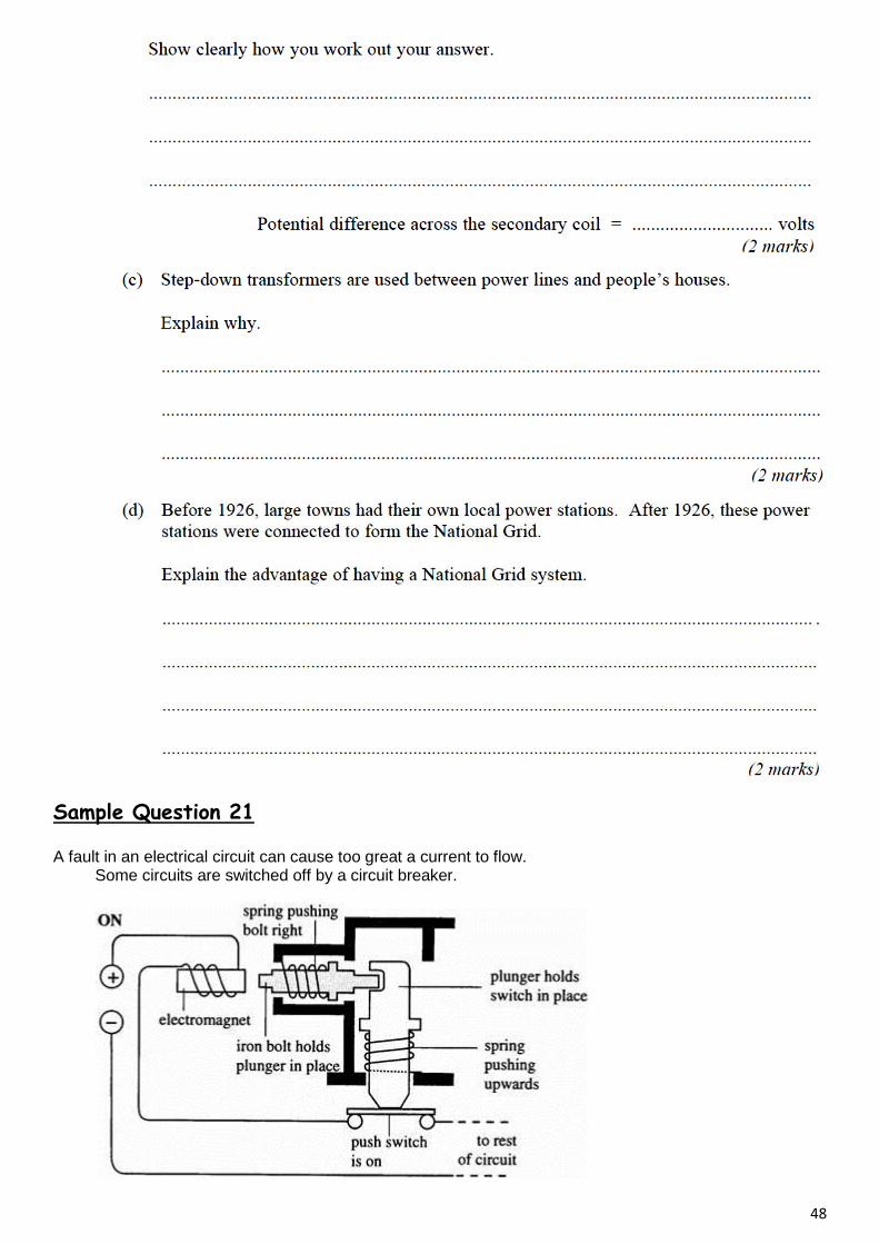
Sample Question 21
A fault in an electrical circuit can cause too great a current to flow. Some circuits are switched off by a circuit breaker.
49
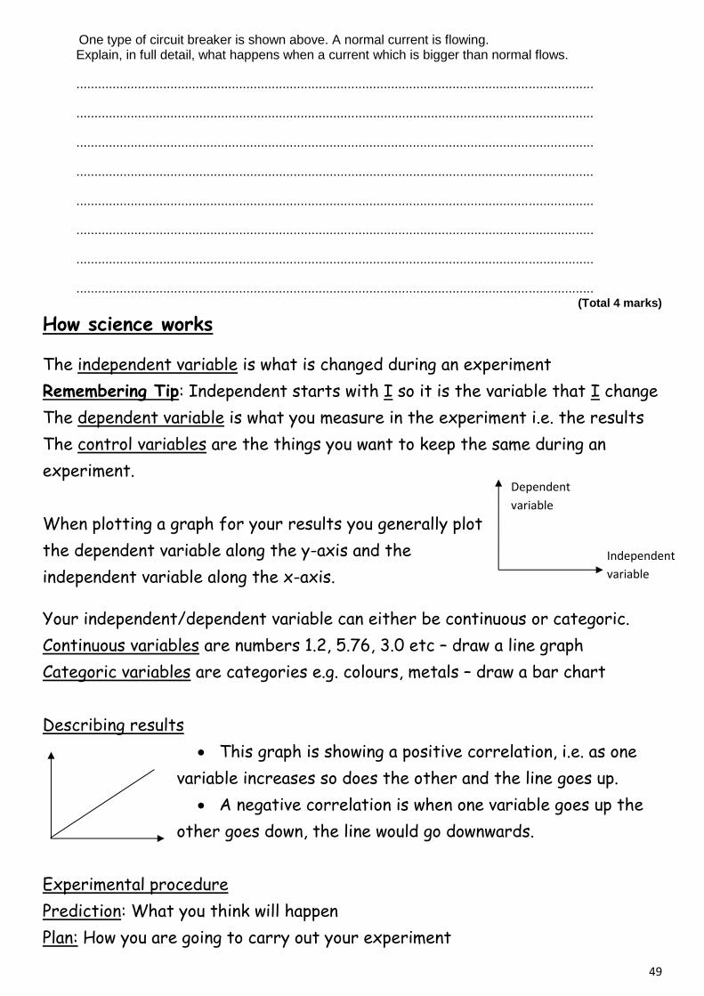
One type of circuit breaker is shown above. A normal current is flowing. Explain, in full detail, what happens when a current which is bigger than normal flows.
...............................................................................................................................................
...............................................................................................................................................
...............................................................................................................................................
...............................................................................................................................................
...............................................................................................................................................
...............................................................................................................................................
...............................................................................................................................................
............................................................................................................................................... (Total 4 marks)
How science works
The independent variable is what is changed during an experiment
Remembering Tip: Independent starts with I so it is the variable that I change
The dependent variable is what you measure in the experiment i.e. the results
The control variables are the things you want to keep the same during an
experiment.
When plotting a graph for your results you generally plot
the dependent variable along the y-axis and the
independent variable along the x-axis.
Your independent/dependent variable can either be continuous or categoric.
Continuous variables are numbers 1.2, 5.76, 3.0 etc – draw a line graph
Categoric variables are categories e.g. colours, metals – draw a bar chart
Describing results
This graph is showing a positive correlation, i.e. as one
variable increases so does the other and the line goes up.
A negative correlation is when one variable goes up the
other goes down, the line would go downwards.
Experimental procedure
Prediction: What you think will happen
Plan: How you are going to carry out your experiment
Dependent
variable
Independent
variable
50
Conclusion: What you have found out from the experiment
Fair test: When you make sure each experiment is set up the same way so the
results can be compared fairly
Repeatable: In experiments you usually repeat measurements and take a mean
(average). This is to ensure you are getting the same results.
Reproducible: If another experimenter can get the same results as you using
their equipment then your finding are correct.
Range: The lowest to highest value you tested
Anomalous: Results that don’t fit in/follow the pattern of the other results
When making a conclusion about an experiment, that conclusion is only valid for
the range investigated.
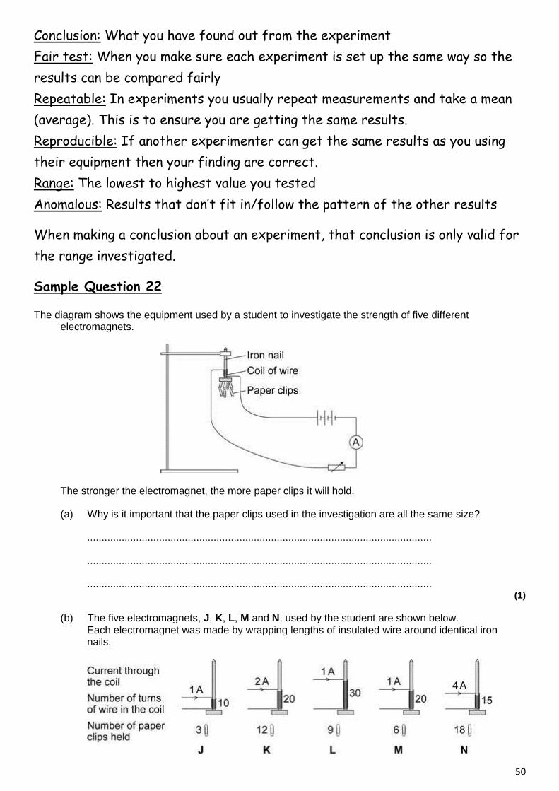
Sample Question 22
The diagram shows the equipment used by a student to investigate the strength of five different electromagnets.
The stronger the electromagnet, the more paper clips it will hold.
(a) Why is it important that the paper clips used in the investigation are all the same size?
........................................................................................................................
........................................................................................................................
........................................................................................................................ (1)
(b) The five electromagnets, J, K, L, M and N, used by the student are shown below. Each electromagnet was made by wrapping lengths of insulated wire around identical iron nails.

51
The student wants to find out how the strength of an electromagnet depends on the number of turns of wire in the coil.
Which electromagnets should the student compare in order to do this?
........................................................................................................................ (1)
(c) The student concluded:
“The strength of an electromagnet is always directly proportional to the number of turns on the coil.”
(i) Explain how the data from the investigation supports the student’s conclusion.
...............................................................................................................
...............................................................................................................
...............................................................................................................
............................................................................................................... (2)
(ii) The student makes one more electromagnet by winding 100 turns onto a nail.
Before testing the electromagnet, the student predicted the number of paper clips that the electromagnet would hold when the current is 1 amp.
How many paper clips should the student predict that the electromagnet would hold?
Show clearly how you work out your answer.
...............................................................................................................
...............................................................................................................
number of paper clips = ..................................... (2)
(iii) When the student tested the electromagnet it held 20 paper clips. This is not what the student predicted.
Explain what the student should do when new data does not seem to support the prediction that was made.
...............................................................................................................
...............................................................................................................
...............................................................................................................
...............................................................................................................
...............................................................................................................
...............................................................................................................
............................................................................................................... (3)
(Total 9 marks)

52
SOLUTIONS TO EXAM QUESTION
Question 1
53
Question 2
(a) (i) X-rays or gamma rays
for 1 mark 1
(ii) passes through flesh; stopped by bone/absorbed
for 1 mark each 2
(b) idea that X-rays cause mutations
gains 1 mark
but X-rays can cause/increase chance of mutations
gains 2 marks
mutations usually harmful/produce abnormal growth serious effect on growing foetus/rapidly growing cells
each for 1 mark [7]
Question 3
Quality of written communication
correct use of three scientific terms from speed / velocity, reflection, density, time, boundary
1
any three from:
different tissues have different densities
ultrasound travels at different speeds / velocities in different tissues
reflection
accept bouncing back
from tissue boundaries
time taken to return 3
[4]
Question 4
54
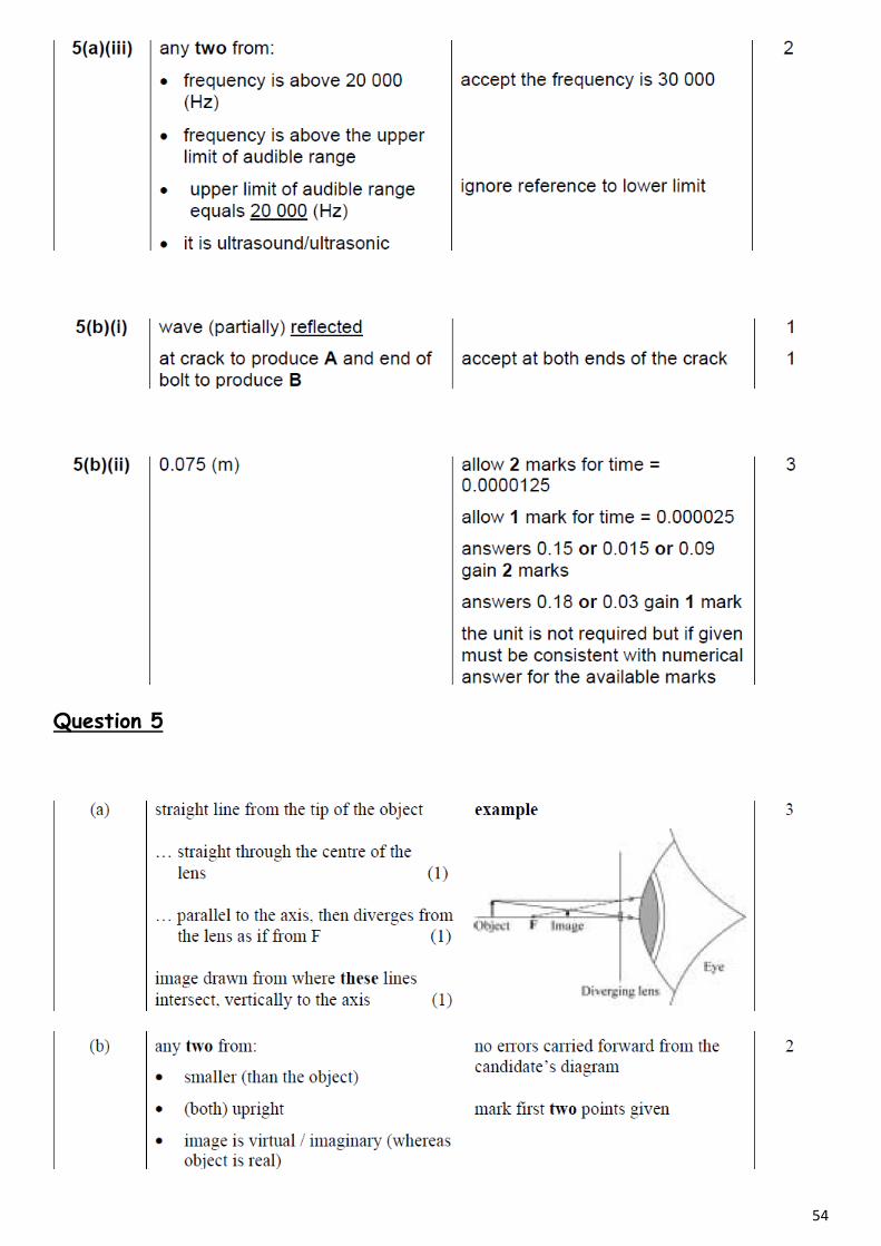
Question 5
55
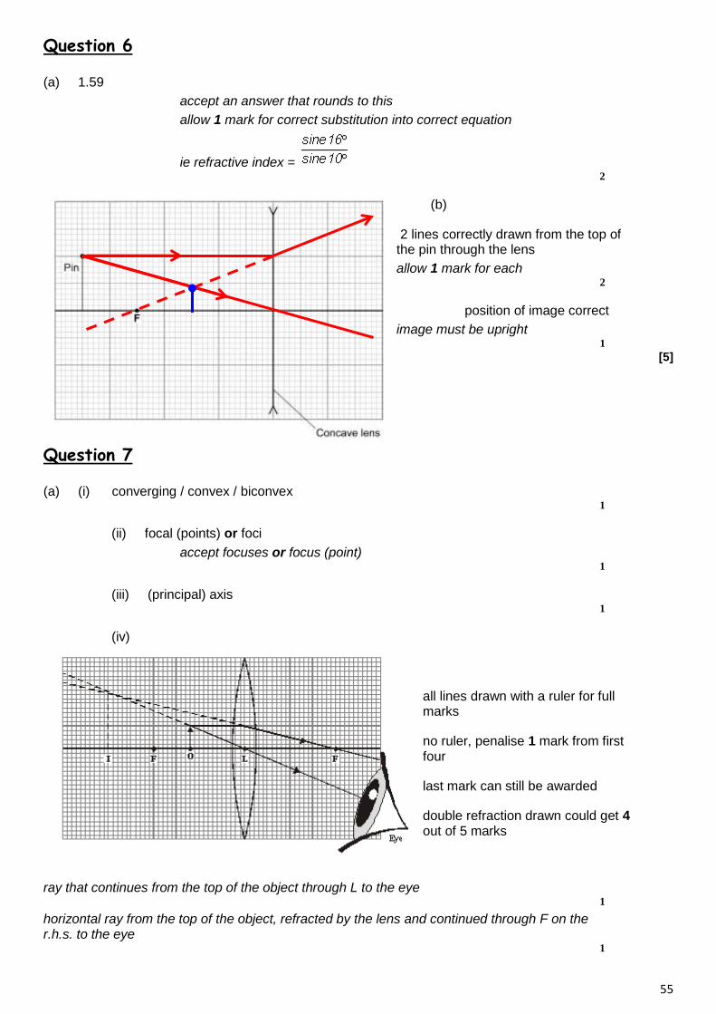
Question 6
(a) 1.59
accept an answer that rounds to this
allow 1 mark for correct substitution into correct equation
ie refractive index = 2
(b)
2 lines correctly drawn from the top of the pin through the lens
allow 1 mark for each 2
position of image correct
image must be upright 1
[5]
Question 7
(a) (i) converging / convex / biconvex 1
(ii) focal (points) or foci
accept focuses or focus (point) 1
(iii) (principal) axis 1
(iv)
all lines drawn with a ruler for full marks
no ruler, penalise 1 mark from first four
last mark can still be awarded
double refraction drawn could get 4 out of 5 marks
ray that continues from the top of the object through L to the eye 1
horizontal ray from the top of the object, refracted by the lens and continued through F on the r.h.s. to the eye
1

56
back projections of these rays (shown as dotted lines) 1
image 25 mm high at 61 mm left of L(tolerance 1 mm ± vertically, 2 mm ± horizontally) 1
at least one arrow shown on real ray and towards the eye but do not credit if contradicted by other arrow(s)
1
(v) formed where imaginary rays intersect / cross or not formed by real rays
accept (virtual image) is imaginary accept cannot be put on screen do not credit just ‘… is not real’
1
(b) (the image) needs to fall on film / sensors / LDRs / CCDs
accept just ‘charged couples’ do not credit ‘… solar cells’ do not accept virtual image cannot be stored
1
either to cause a (chemical) reaction or to be digitalised for credit response must be appropriate to camera type
1
object (should be) on the far side of F / the focus (from the lens)
or … more than the focal length (away from the lens) allow ‘beyond the focus’
or object should be more than twice the distance / 2F (from the lens) (2 marks)
or … more than twice the focal length (away from the lens) (2 marks)
1
[12]
Question 8
(a) ciliary muscle 1
cornea 1
(b) (i) moved further (from his eyes) 1
(ii) rays between lens and eye converging 1
rays inside eye focus on the retina 1
(c) any two from:
• both use a converging lens
• image formed is real
• image is inverted
• image in eye formed on retina, image in camera formed on film / CCDs
• amount of light entering eye and camera can be controlled 2
[7]
57
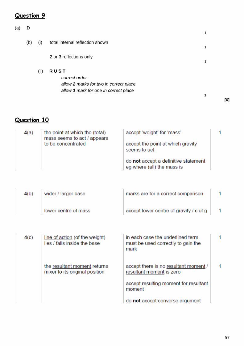
Question 9
(a) D 1
(b) (i) total internal reflection shown 1
2 or 3 reflections only 1
(ii) R U S T
correct order
allow 2 marks for two in correct place
allow 1 mark for one in correct place 3
[6]
Question 10
58
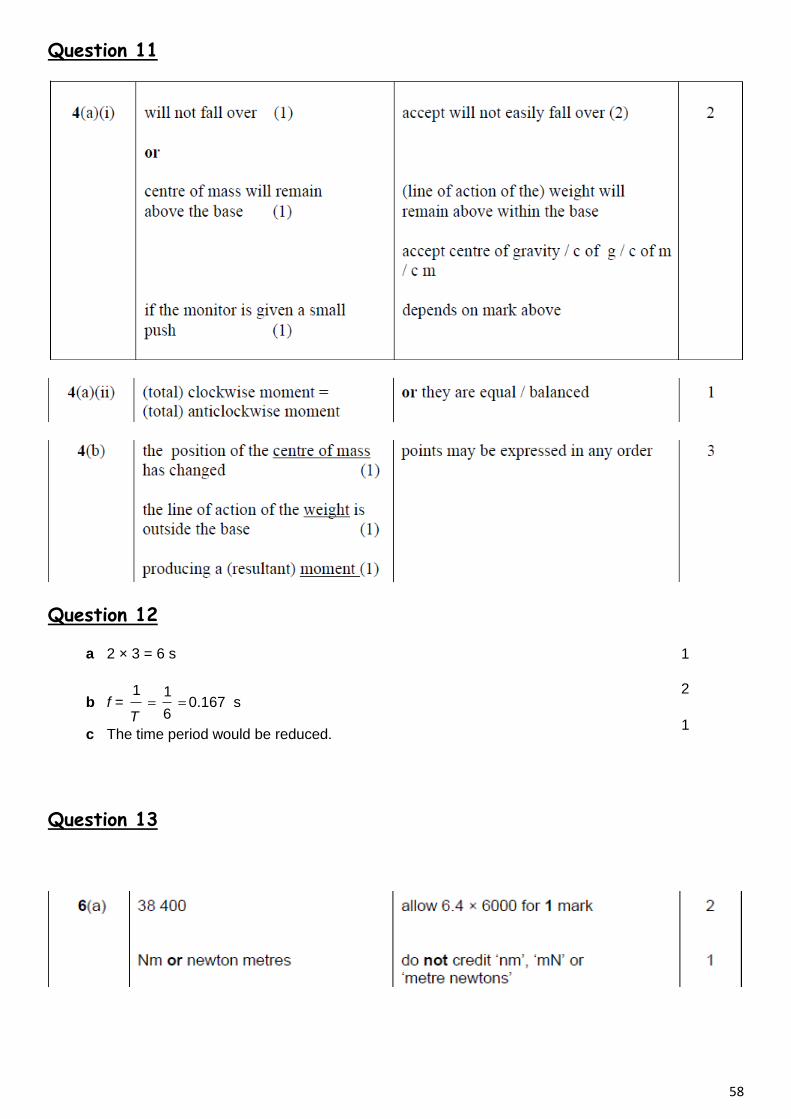
Question 11
Question 12
a 2 × 3 = 6 s
b f = 6
11
T0.167 s
c The time period would be reduced.
1
2
1
Question 13
59
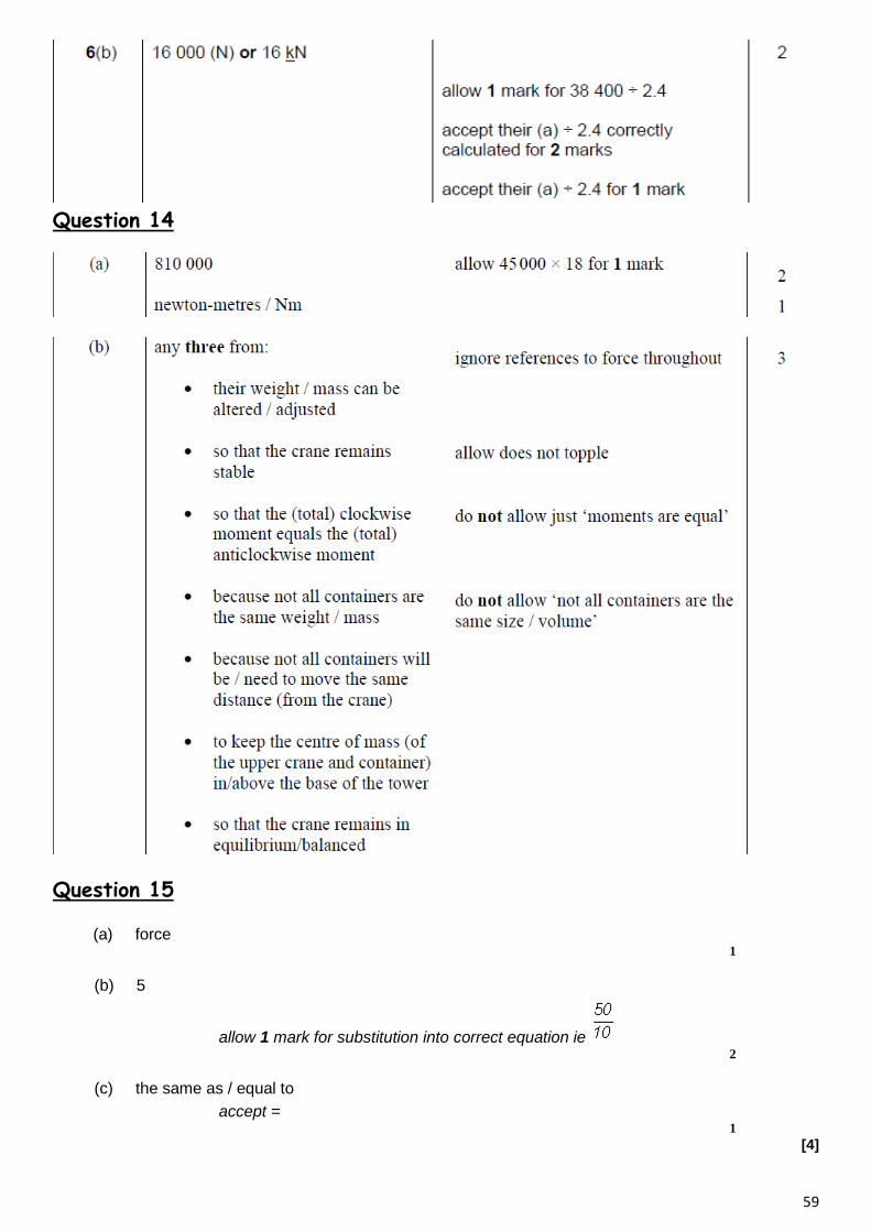
Question 14
Question 15
(a) force 1
(b) 5
allow 1 mark for substitution into correct equation ie 2
(c) the same as / equal to
accept = 1
[4]
60
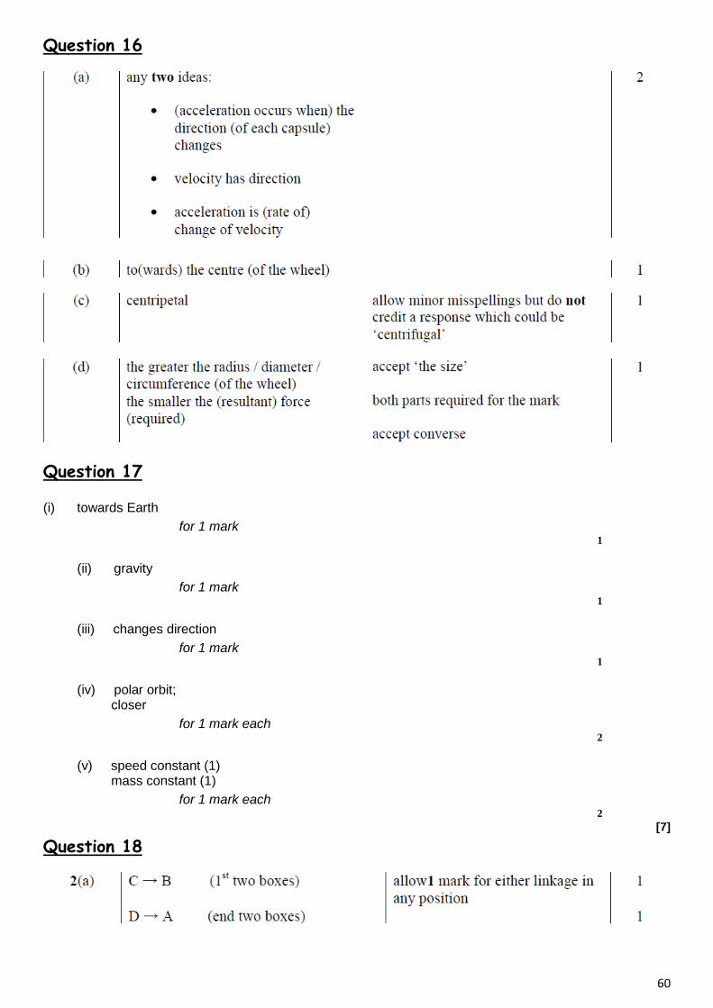
Question 16
Question 17
(i) towards Earth
for 1 mark 1
(ii) gravity
for 1 mark 1
(iii) changes direction
for 1 mark 1
(iv) polar orbit; closer
for 1 mark each 2
(v) speed constant (1) mass constant (1)
for 1 mark each 2
[7]
Question 18

61
Question 19
Question 20

62

63
Question 21
electromagnet becomes stronger (not becomes magnetic) iron moves left – implied OK plunger goes up push switch goes to off or circuit broken unless plunger moves down
for 1 mark each [4]
Question 22
(a) so the results can be compared fairly
fair test is insufficient 1
(b) J L M
all 3 required and no other 1
(c) (i) for a given current the number of paper clips increases by the same factor as the number of turns
1
plus a mathematical explanation using the data eg a current of 1 A with 10 turns picks up 3 clips, a current of 1 A with 20 turns picks up 6 clips
1
(ii) 30
allow 1 mark for showing correct use of figures eg 20 turns × 5 = 100 turns
2
(iii) check the new data / repeat the experiment 1
to identify any anomalous results 1
then reconsider prediction / hypothesis in the light of new evidence
1
[9]