physics notes units 3 & 4 - lorimer...physics notes units 3 & 4 hong ky ho 1 table of...
TRANSCRIPT

0
Physics Notes Units 3 & 4 Hong Ky Ho
1
Table of Contents
U3 AS1: Motion in One and Two Dimensions
Basic Concepts of Motion 2
Forces 2
Momentum and Impulse 3
Work and Energy 4
Circular Motion 4
Gravitation and Satellites 5
Energy Changes in Gravitational Fields 5
Apparent and True Weight 6
U3 AS2: Electronics and Photonics
Basic Concepts of Electricity 7
Voltage Divider Formula 7
Electrical Components 8
Photonics 8
U4 AS1: Electric Power
Basic Concepts of Magnetism 10
Magnetic Fields and Forces 10
Electromagnetic Induction 11
Electric Motors and Generator 11
Power Generation 12
U4 AS2: Interactions of Light and Matter
Introduction 13
The Wave Model Vs. The Particle Model 13
The Wave Model of Light in Depth 14
The Corpuscular Model of Light in Depth 16
Matter Waves 19
Quantised Atomic Energy Levels 19
Standing Waves 20
Colour Code
Red: Important Things to Note
Blue: Formulae
2
Unit 3 - Area of Study One: Motion in One and Two Dimensions
Basic Concepts of Motion
Physical quantities can be divided into two subgroups. Scalars solely consist of a magnitude or a number, while
vectors require an indication of both magnitude and direction.
Displacement is a vector quantity, defined as how far an object is at the finish, compared to at the start in a
direct line. It is described with both a magnitude and direction.
Distance is a scalar quantity and describes how far an object moves in total, regardless of direction.
Velocity is a vector quantity, defined by the rate of change of displacement with respect to time. It is described
with both a magnitude and direction.
Average velocity = displacement / time taken.
Instantaneous velocity = velocity of a body at a particular instant in time.
Speed is a scalar quantity, defined by the rate of change of distance with respect to time. Being a scalar quantity,
it only requires a magnitude to be described.
Average speed = distance / time taken.
Instantaneous speed = speed of a body at a particular instant in time.
Acceleration is a vector quantity, defined by the rate of change of velocity with respect to time. It is described
with both a magnitude and direction.
Average acceleration = change in velocity / time taken.
Instantaneous acceleration = acceleration of a body at a particular instant in time.
Exam tip: When adding vectors, remember to take the direction of the different vectors into account. For example, if it is
in the opposite direction, then there should be a negative in front of the respective value. E.g. 12 – (-10) = 12 + 10 = 22
The equations of motion are used when the acceleration of an object is constant. They are:
s = ½(u + v)t where: s is displacement in m
v = u + at u is initial velocity in ms-1
s = ut + ½at2 v is final velocity in ms-1
s = vt - ½at2 a is acceleration in ms-2
v2 = u2 + 2as t is time in secs
In cases when acceleration is not constant (or even when it is), motion can be represented graphically:
Position-time graphs: These indicate the position (y-axis) relative to time (x-axis).
The instantaneous velocity can be determined by taking the gradient of the tangent at any point in time.
Velocity-time graphs: These indicate the velocity (y-axis) in respect to time (x-axis).
The displacement of the object can be found by calculating the area underneath the graph (i.e. signs of the
area are included in the calculations), and the distance will be the scalar sum of the areas (i.e. signs are not
included).
The instantaneous acceleration can be found by taking the gradient of the tangent of any point in time.
Acceleration-time graphs: These indicate the acceleration (y-axis) relative to time (x-axis).
The change in velocity can be determined by finding the area under the graph.
Forces
Forces are defined as a push or a pull. Common forces include:
Net force: The net or resultant force is never a force in itself but a result of a combination of other forces, some
of which are listed underneath. Net forces are observed when there is acceleration or deceleration of an object.
In circular motion, the net force is referred to as the centripetal force.
Weight: Force exerted on a mass in a gravitational field. Weight is calculated using the formula: W = mg (m is
mass of the object in kg, g is acceleration due to gravity or strength of the magnetic field in ms-2 or Nkg-1, w is the
weight force in N)
Normal reaction force: Force exerted on an object by the surface it is on, which acts perpendicular to the surface.
The normal force can be found by the formula: N = mgcos(θ) (m is mass of the object in kg, g is acceleration due
to gravity or strength of the magnetic field in ms-2 or Nkg-1, θ is the angle of deviation from the horizontal plane
in degrees).

3
Tension: Force exerted from an object being pulled, trying to extend its length.
Friction: Friction always act opposite to an object’s motion. However, this does not mean it does not aid motion.
Sample answer: Give example of friction aiding motion of the wheels of a trolley.
When a wheel rotates, friction exists between the wheel and the Earth. Without the friction, the object would not move.
In accordance with Newton’s Third Law, there is a pair of equal and opposite forces: the frictional force of the wheel on
the Earth and the frictional force of the Earth on the wheel. The Earth has a large mass, so its acceleration is negligible,
but the trolley will experience acceleration due to its smaller mass.
Newton’s laws of motion:
Newton’s First Law: Every object will continue to be at rest or travel with constant velocity (i.e. ∑F = 0), unless it
experiences an unbalanced force. Inertia is the resistance of any physical object to a change in its state of motion.
Newton’s Second Law: The acceleration of a body experiencing an unbalanced force is directly proportional to
the net force and inversely proportional to the mass of a body: F = ma (F is the net force in N, m is the mass in kg
and a is acceleration in ms-2).
Newton’s Third Law: When one body exerts a force on another body (an action force), the second body exerts
an equal force in the opposite direction on the first (the reaction force). These two forces are called action-
reaction pair and must act on different bodies (i.e. cannot be added together). F(A on B) = -F(B on A)
Note that Newton’s Third Law can only be applied to cases where there are only two objects and where the pair
of forces cannot exist without each other.
The centre of mass is a single point where all of the mass of an object is said to be located. This is used to simplify
problems.
When analysing motion on an inclined plane, it is useful to consider force vectors as having components, and these
components can add or subtract each other.
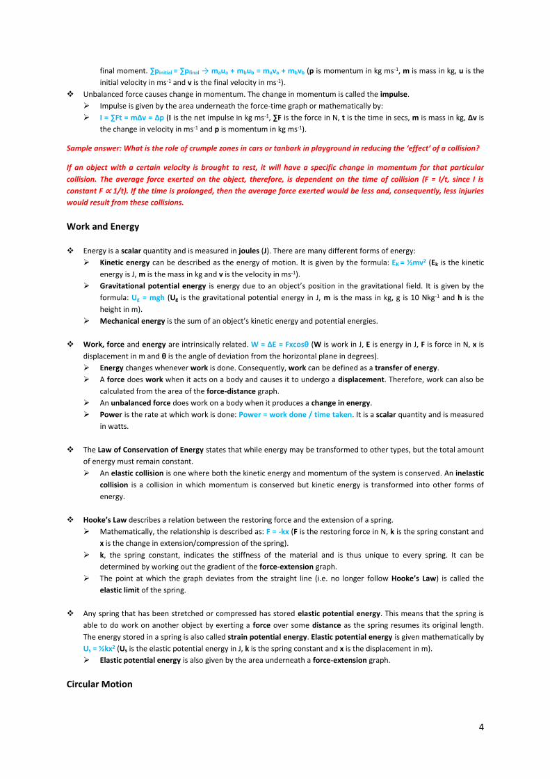
A projectile is any object that is thrown or projected into the air and is moving freely. Projectile motion is considered
parabolic and symmetrical, unless air resistance is taken into account.
If air resistance is ignored, the only force acting on a projectile during its flight is
its weight, which is the force due to gravity. The weight force acts vertically and
therefore, has no effect on horizontal motion. The horizontal and vertical
components of motion are independent of each other and must be treated
separately.
The vertical component of the motion of a projectile accelerates 9.8ms-2
downwards, while the horizontal component of motion moves with constant
velocity.
When air resistance is considered, the net force acting on a projectile will not be
vertically down, nor will its acceleration. Under these conditions, the path of the projectile is not parabolic.
Momentum and Impulse
Momentum is the inertial energy of an object or its tendency to continue in its direction of motion.
It is a vector quantity and is defined by the mathematical relationship: p = mv (p is momentum in kg ms-1, m is
mass in kg and v is velocity in ms-1)
The Law of Conservation of Momentum states that, in an interaction between two or more objects in an isolated
system, the total momentum of the system will remain constant, i.e. the total initial momentum must equal the
4
final moment. ∑pinitial = ∑pfinal → maua + mbub = mava + mbvb (p is momentum in kg ms-1, m is mass in kg, u is the
initial velocity in ms-1 and v is the final velocity in ms-1).
Unbalanced force causes change in momentum. The change in momentum is called the impulse.
Impulse is given by the area underneath the force-time graph or mathematically by:
I = ∑Ft = mΔv = Δp (I is the net impulse in kg ms-1, ∑F is the force in N, t is the time in secs, m is mass in kg, Δv is
the change in velocity in ms-1 and p is momentum in kg ms-1).
Sample answer: What is the role of crumple zones in cars or tanbark in playground in reducing the ‘effect’ of a collision?
If an object with a certain velocity is brought to rest, it will have a specific change in momentum for that particular
collision. The average force exerted on the object, therefore, is dependent on the time of collision (F = I/t, since I is
constant F ∝ 1/t). If the time is prolonged, then the average force exerted would be less and, consequently, less injuries
would result from these collisions.
Work and Energy
Energy is a scalar quantity and is measured in joules (J). There are many different forms of energy:
Kinetic energy can be described as the energy of motion. It is given by the formula: EK = ½mv2 (Ek is the kinetic
energy is J, m is the mass in kg and v is the velocity in ms-1).
Gravitational potential energy is energy due to an object’s position in the gravitational field. It is given by the
formula: Ug = mgh (Ug is the gravitational potential energy in J, m is the mass in kg, g is 10 Nkg-1 and h is the
height in m).
Mechanical energy is the sum of an object’s kinetic energy and potential energies.
Work, force and energy are intrinsically related. W = ΔE = Fxcosθ (W is work in J, E is energy in J, F is force in N, x is
displacement in m and θ is the angle of deviation from the horizontal plane in degrees).
Energy changes whenever work is done. Consequently, work can be defined as a transfer of energy.
A force does work when it acts on a body and causes it to undergo a displacement. Therefore, work can also be
calculated from the area of the force-distance graph.
An unbalanced force does work on a body when it produces a change in energy.
Power is the rate at which work is done: Power = work done / time taken. It is a scalar quantity and is measured
in watts.
The Law of Conservation of Energy states that while energy may be transformed to other types, but the total amount
of energy must remain constant.
An elastic collision is one where both the kinetic energy and momentum of the system is conserved. An inelastic
collision is a collision in which momentum is conserved but kinetic energy is transformed into other forms of
energy.
Hooke’s Law describes a relation between the restoring force and the extension of a spring.
Mathematically, the relationship is described as: F = -kx (F is the restoring force in N, k is the spring constant and
x is the change in extension/compression of the spring).
k, the spring constant, indicates the stiffness of the material and is thus unique to every spring. It can be
determined by working out the gradient of the force-extension graph.
The point at which the graph deviates from the straight line (i.e. no longer follow Hooke’s Law) is called the
elastic limit of the spring.
Any spring that has been stretched or compressed has stored elastic potential energy. This means that the spring is
able to do work on another object by exerting a force over some distance as the spring resumes its original length.
The energy stored in a spring is also called strain potential energy. Elastic potential energy is given mathematically by
Us = ½kx2 (Us is the elastic potential energy in J, k is the spring constant and x is the displacement in m).
Elastic potential energy is also given by the area underneath a force-extension graph.
Circular Motion
5
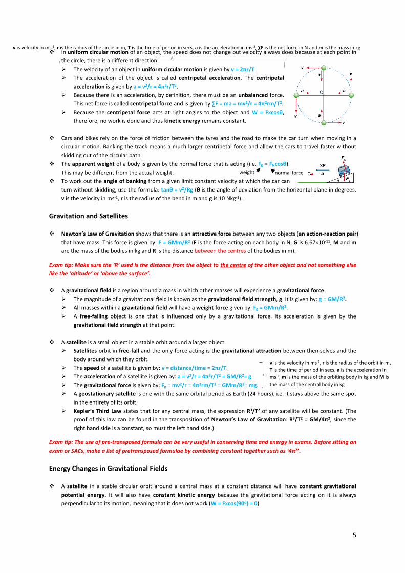
In uniform circular motion of an object, the speed does not change but velocity always does because at each point in
the circle, there is a different direction.
The velocity of an object in uniform circular motion is given by v = 2πr/T.
The acceleration of the object is called centripetal acceleration. The centripetal
acceleration is given by a = v2/r = 4π2r/T2.
Because there is an acceleration, by definition, there must be an unbalanced force.
This net force is called centripetal force and is given by ∑F = ma = mv2/r = 4π2rm/T2.
Because the centripetal force acts at right angles to the object and W = Fxcosθ,
therefore, no work is done and thus kinetic energy remains constant.
Cars and bikes rely on the force of friction between the tyres and the road to make the car turn when moving in a
circular motion. Banking the track means a much larger centripetal force and allow the cars to travel faster without
skidding out of the circular path.
The apparent weight of a body is given by the normal force that is acting (i.e. Fg = FNcosθ).
This may be different from the actual weight.
To work out the angle of banking from a given limit constant velocity at which the car can
turn without skidding, use the formula: tanθ = v2/Rg (θ is the angle of deviation from the horizontal plane in degrees,
v is the velocity in ms-1, r is the radius of the bend in m and g is 10 Nkg-1).
Gravitation and Satellites
Newton’s Law of Gravitation shows that there is an attractive force between any two objects (an action-reaction pair)
that have mass. This force is given by: F = GMm/R2 (F is the force acting on each body in N, G is 6.67×10⁻¹¹, M and m
are the mass of the bodies in kg and R is the distance between the centres of the bodies in m).
Exam tip: Make sure the ‘R’ used is the distance from the object to the centre of the other object and not something else
like the ‘altitude’ or ‘above the surface’.
A gravitational field is a region around a mass in which other masses will experience a gravitational force.
The magnitude of a gravitational field is known as the gravitational field strength, g. It is given by: g = GM/R2.
All masses within a gravitational field will have a weight force given by: Fg = GMm/R2.
A free-falling object is one that is influenced only by a gravitational force. Its acceleration is given by the
gravitational field strength at that point.
A satellite is a small object in a stable orbit around a larger object. Satellites orbit in free-fall and the only force acting is the gravitational attraction between themselves and the
body around which they orbit.
The speed of a satellite is given by: v = distance/time = 2πr/T.
The acceleration of a satellite is given by: a = v2/r = 4π2r/T2 = GM/R2= g.
The gravitational force is given by: Fg = mv2/r = 4π2rm/T2 = GMm/R2= mg.
A geostationary satellite is one with the same orbital period as Earth (24 hours), i.e. it stays above the same spot
in the entirety of its orbit.
Kepler’s Third Law states that for any central mass, the expression R3/T2 of any satellite will be constant. (The
proof of this law can be found in the transposition of Newton’s Law of Gravitation: R3/T2 = GM/4π2, since the
right hand side is a constant, so must the left hand side.)
Exam tip: The use of pre-transposed formula can be very useful in conserving time and energy in exams. Before sitting an
exam or SACs, make a list of pretransposed formulae by combining constant together such as ‘4π2’.
Energy Changes in Gravitational Fields
A satellite in a stable circular orbit around a central mass at a constant distance will have constant gravitational
potential energy. It will also have constant kinetic energy because the gravitational force acting on it is always
perpendicular to its motion, meaning that it does not work (W = Fxcos(90o) = 0)
weight normal force
v is velocity in ms-1, r is the radius of the circle in m, T is the time of period in secs, a is the acceleration in ms-2, ∑F is the net force in N and m is the mass in kg
v is the velocity in ms-1, r is the radius of the orbit in m,
T is the time of period in secs, a is the acceleration in
ms-2, m is the mass of the orbiting body in kg and M is
the mass of the central body in kg
6
The total energy of a body moving freely through a gravitational field is constant even though the relative amounts
of kinetic energy and gravitational potential energy may change.
The area under a force-distance graph equals the work done by the gravitational field.
The area under a gravitational field-distance graph equals the work done by the gravitational field per kilogram
of mass.
Apparent and True Weight
True weight is described by the formula: W = mg. Since there is virtually no place where there is no gravitational field,
an object will always experience a weight force.
Apparent weight is the sensation of weight. It is equal in magnitude to the normal reaction force that the supporting
surface exerts on us (i.e. how strongly the surface pushes us up or down).
Apparent weightlessness is achieved when an object falls with an acceleration equal to the gravitational field
strength. For example, astronauts in a satellite in stable orbit will feel weightless as both the astronauts and the
satellite are in constant free-fall.
7
Unit 3 - Area of Study Two: Electronics and Photonics
Basic Concepts of Electricity
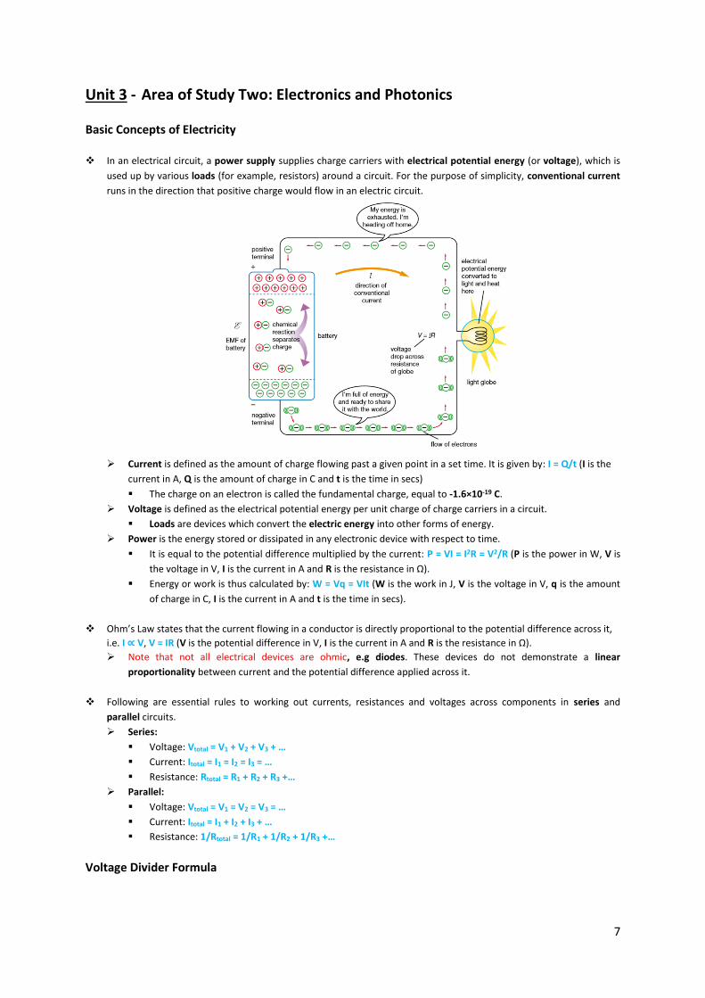
In an electrical circuit, a power supply supplies charge carriers with electrical potential energy (or voltage), which is
used up by various loads (for example, resistors) around a circuit. For the purpose of simplicity, conventional current
runs in the direction that positive charge would flow in an electric circuit.
Current is defined as the amount of charge flowing past a given point in a set time. It is given by: I = Q/t (I is the
current in A, Q is the amount of charge in C and t is the time in secs)
The charge on an electron is called the fundamental charge, equal to -1.6×10⁻¹⁹ C.
Voltage is defined as the electrical potential energy per unit charge of charge carriers in a circuit.
Loads are devices which convert the electric energy into other forms of energy.
Power is the energy stored or dissipated in any electronic device with respect to time.
It is equal to the potential difference multiplied by the current: P = VI = I2R = V2/R (P is the power in W, V is
the voltage in V, I is the current in A and R is the resistance in Ω).
Energy or work is thus calculated by: W = Vq = VIt (W is the work in J, V is the voltage in V, q is the amount
of charge in C, I is the current in A and t is the time in secs).
Ohm’s Law states that the current flowing in a conductor is directly proportional to the potential difference across it,
i.e. I ∝ V, V = IR (V is the potential difference in V, I is the current in A and R is the resistance in Ω).
Note that not all electrical devices are ohmic, e.g diodes. These devices do not demonstrate a linear
proportionality between current and the potential difference applied across it.
Following are essential rules to working out currents, resistances and voltages across components in series and
parallel circuits.
Series:
Voltage: Vtotal = V1 + V2 + V3 + …
Current: Itotal = I1 = I2 = I3 = …
Resistance: Rtotal = R1 + R2 + R3 +…
Parallel:
Voltage: Vtotal = V1 = V2 = V3 = …
Current: Itotal = I1 + I2 + I3 + …
Resistance: 1/Rtotal = 1/R1 + 1/R2 + 1/R3 +…
Voltage Divider Formula
8
In a circuit that contain multiple resistors, the voltage drop across one of the
resistors can be calculated using the formula Vout/Vin = R/RTotal if the resistor
being looked at is R2.
Exam Tip: Qualitative questions are often asked of voltage divider circuit in the
manner: If R1 is increased, how must R2 be changed to ensure that the switch on
voltage is the same as before? The important thing to note is that the voltage ratio
must be maintained, so if R1 increases, so must R2. There is a direct proportionality relationship.
Electrical Components
Thermistors are devices whose resistance decreases sharply with increases in temperature.
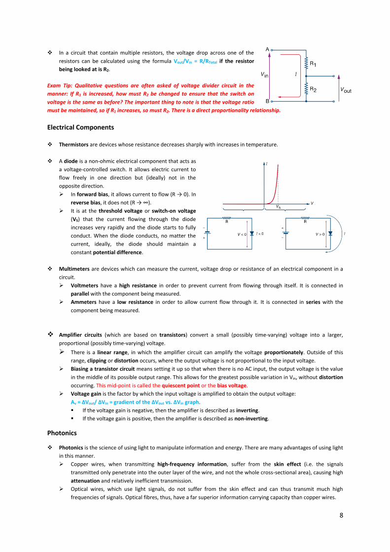
A diode is a non-ohmic electrical component that acts as
a voltage-controlled switch. It allows electric current to
flow freely in one direction but (ideally) not in the
opposite direction.
In forward bias, it allows current to flow (R → 0). In
reverse bias, it does not (R → ∞).
It is at the threshold voltage or switch-on voltage
(VS) that the current flowing through the diode
increases very rapidly and the diode starts to fully
conduct. When the diode conducts, no matter the
current, ideally, the diode should maintain a
constant potential difference.
Multimeters are devices which can measure the current, voltage drop or resistance of an electrical component in a
circuit.
Voltmeters have a high resistance in order to prevent current from flowing through itself. It is connected in
parallel with the component being measured.
Ammeters have a low resistance in order to allow current flow through it. It is connected in series with the
component being measured.
Amplifier circuits (which are based on transistors) convert a small (possibly time-varying) voltage into a larger,
proportional (possibly time-varying) voltage.
There is a linear range, in which the amplifier circuit can amplify the voltage proportionately. Outside of this
range, clipping or distortion occurs, where the output voltage is not proportional to the input voltage. Biasing a transistor circuit means setting it up so that when there is no AC input, the output voltage is the value
in the middle of its possible output range. This allows for the greatest possible variation in Vin, without distortion
occurring. This mid-point is called the quiescent point or the bias voltage.
Voltage gain is the factor by which the input voltage is amplified to obtain the output voltage:
Av = ΔVout/ ΔVin = gradient of the ΔVout vs. ΔVin graph.
If the voltage gain is negative, then the amplifier is described as inverting.
If the voltage gain is positive, then the amplifier is described as non-inverting.
Photonics
Photonics is the science of using light to manipulate information and energy. There are many advantages of using light
in this manner.
Copper wires, when transmitting high-frequency information, suffer from the skin effect (i.e. the signals
transmitted only penetrate into the outer layer of the wire, and not the whole cross-sectional area), causing high
attenuation and relatively inefficient transmission.
Optical wires, which use light signals, do not suffer from the skin effect and can thus transmit much high
frequencies of signals. Optical fibres, thus, have a far superior information carrying capacity than copper wires.
9
Optical transducers are devices that convert light energy (which often can contain information) into electrical energy
and vice versa.
Light dependent resistors (LDRs) are devices whose resistance changes depending upon illumination. Their
response is non-linear and slow.
Photodiodes are devices which, in photoconductive mode (i.e. when reverse biased), create a photocurrent that
depends upon illumination. The response is linear and fast.
Phototransistors are also devices that can create a current that depends upon illumination. They have a high
optical gain, so they are ideal for low-light situations. The response is linear, and the response time moderate.
Light-emitting diodes (LEDs) emit an intensity of light that is directly proportional to their forward-biased current.
Its light output can be modulated rapidly, and it has a narrow range of emission wavelengths.
Laser diodes (LD) also emit an intensity of light that is directly proportional to their forward-biased current.
However, it emits laser light and has a much more narrow range of emission wavelengths (meaning less
dispersion).
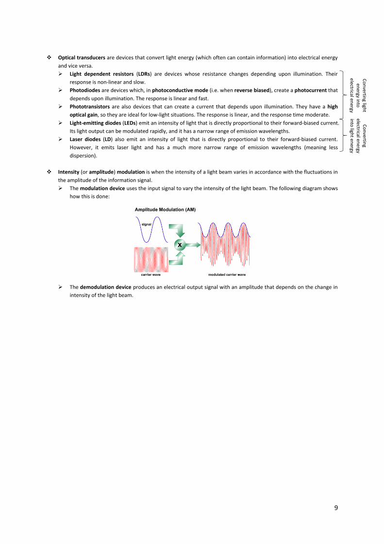
Intensity (or amplitude) modulation is when the intensity of a light beam varies in accordance with the fluctuations in
the amplitude of the information signal.
The modulation device uses the input signal to vary the intensity of the light beam. The following diagram shows
how this is done:
The demodulation device produces an electrical output signal with an amplitude that depends on the change in
intensity of the light beam.
Co
nvertin
g light
energy in
to
electrical energy
Co
nvertin
g electrical en
ergy in
to ligh
t en
ergy
10
Unit 4 - Area of Study One: Electric Power
Basic Concepts of Magnetism
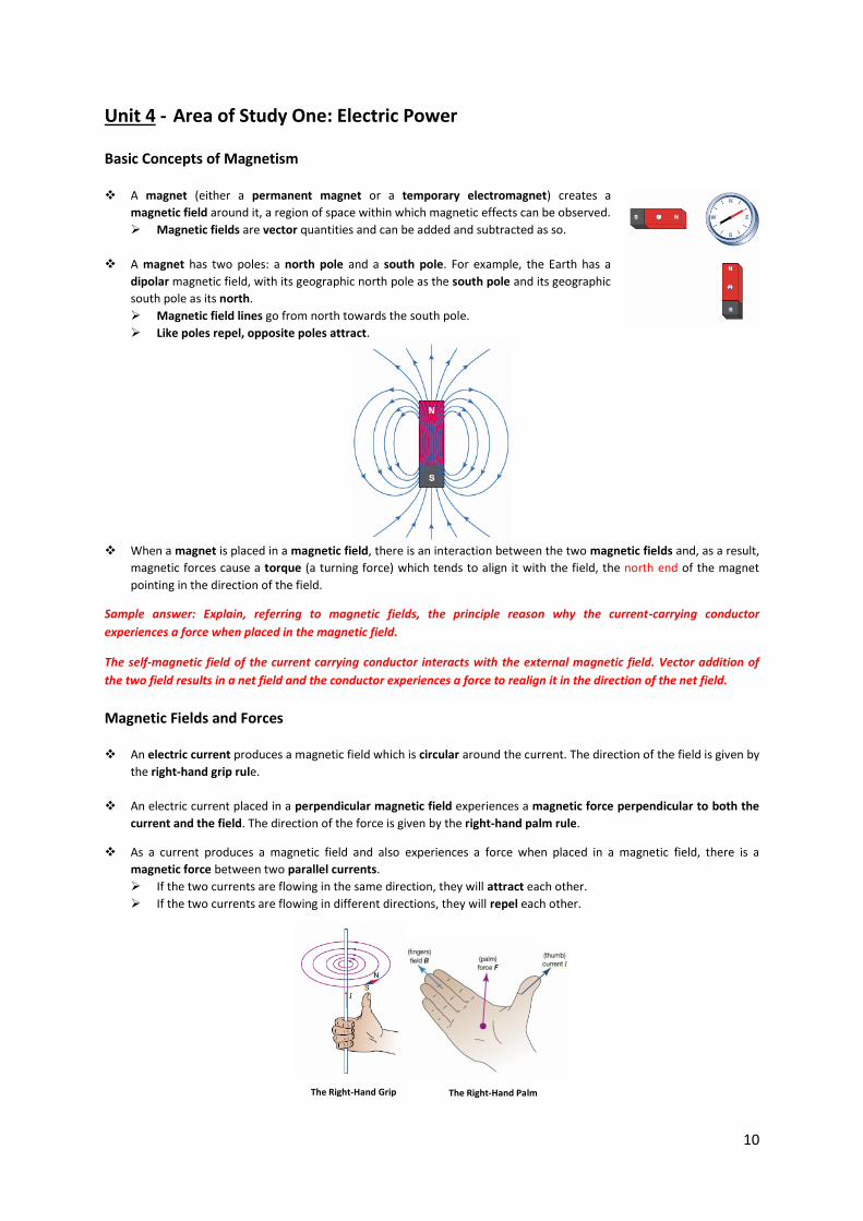
A magnet (either a permanent magnet or a temporary electromagnet) creates a
magnetic field around it, a region of space within which magnetic effects can be observed. Magnetic fields are vector quantities and can be added and subtracted as so.
A magnet has two poles: a north pole and a south pole. For example, the Earth has a
dipolar magnetic field, with its geographic north pole as the south pole and its geographic
south pole as its north.
Magnetic field lines go from north towards the south pole.
Like poles repel, opposite poles attract.
When a magnet is placed in a magnetic field, there is an interaction between the two magnetic fields and, as a result,
magnetic forces cause a torque (a turning force) which tends to align it with the field, the north end of the magnet
pointing in the direction of the field.
Sample answer: Explain, referring to magnetic fields, the principle reason why the current-carrying conductor
experiences a force when placed in the magnetic field.
The self-magnetic field of the current carrying conductor interacts with the external magnetic field. Vector addition of
the two field results in a net field and the conductor experiences a force to realign it in the direction of the net field.
Magnetic Fields and Forces
An electric current produces a magnetic field which is circular around the current. The direction of the field is given by
the right-hand grip rule.
An electric current placed in a perpendicular magnetic field experiences a magnetic force perpendicular to both the
current and the field. The direction of the force is given by the right-hand palm rule.
As a current produces a magnetic field and also experiences a force when placed in a magnetic field, there is a
magnetic force between two parallel currents.
If the two currents are flowing in the same direction, they will attract each other.
If the two currents are flowing in different directions, they will repel each other.
The Right-Hand Grip
Rule The Right-Hand Palm
Rule
11
Exam Tip: Use your right hand!
The force on a wire carrying a current in a magnetic field is given by: F = nBIlsinθ (n is the number of coils, B is the
magnetic field strength in T, l is the length of the conductor in m, I is the magnitude of the current in A and θ is the
angle the current makes with the magnetic field in degrees).
Magnetic field strength is measured in units of teslas (T). A field of 1 tesla is a very strong field; e.g. Earth’s
magnetic field is only 5 × 10⁻⁵ T.
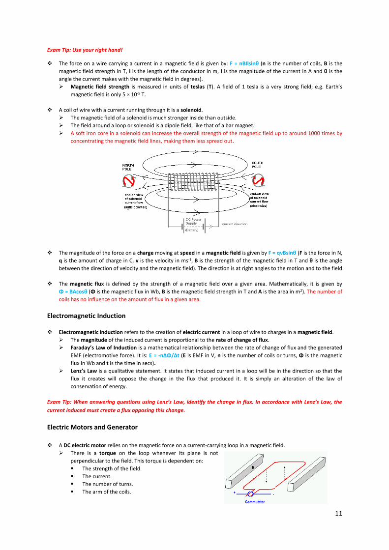
A coil of wire with a current running through it is a solenoid.
The magnetic field of a solenoid is much stronger inside than outside.
The field around a loop or solenoid is a dipole field, like that of a bar magnet.
A soft iron core in a solenoid can increase the overall strength of the magnetic field up to around 1000 times by
concentrating the magnetic field lines, making them less spread out.
The magnitude of the force on a charge moving at speed in a magnetic field is given by F = qvBsinθ (F is the force in N,
q is the amount of charge in C, v is the velocity in ms-1, B is the strength of the magnetic field in T and θ is the angle
between the direction of velocity and the magnetic field). The direction is at right angles to the motion and to the field.
The magnetic flux is defined by the strength of a magnetic field over a given area. Mathematically, it is given by
Φ = BAcosθ (Φ is the magnetic flux in Wb, B is the magnetic field strength in T and A is the area in m2). The number of
coils has no influence on the amount of flux in a given area.
Electromagnetic Induction
Electromagnetic induction refers to the creation of electric current in a loop of wire to charges in a magnetic field.
The magnitude of the induced current is proportional to the rate of change of flux.
Faraday’s Law of Induction is a mathematical relationship between the rate of change of flux and the generated
EMF (electromotive force). It is: Ε = -nΔΦ/Δt (E is EMF in V, n is the number of coils or turns, Φ is the magnetic
flux in Wb and t is the time in secs).
Lenz’s Law is a qualitative statement. It states that induced current in a loop will be in the direction so that the
flux it creates will oppose the change in the flux that produced it. It is simply an alteration of the law of
conservation of energy.
Exam Tip: When answering questions using Lenz’s Law, identify the change in flux. In accordance with Lenz’s Law, the
current induced must create a flux opposing this change.
Electric Motors and Generator
A DC electric motor relies on the magnetic force on a current-carrying loop in a magnetic field.
There is a torque on the loop whenever its plane is not
perpendicular to the field. This torque is dependent on:
The strength of the field.
The current.
The number of turns.
The arm of the coils.
12
The loop keeps rotating because the direction of current, and hence torque, is reversed each half turn by a split-
ring commutator.
The armature of a practical motor consists of many loops that are fed current by the commutator when they are
in the position of maximum torque.
Sample answer: What is the role of a split ring commutator in an electric motor?
The split ring commutator reverses the direction of current when the plane of the loop becomes perpendicular to the
magnetic field to ensure that the loop continues its rotation in one direction.
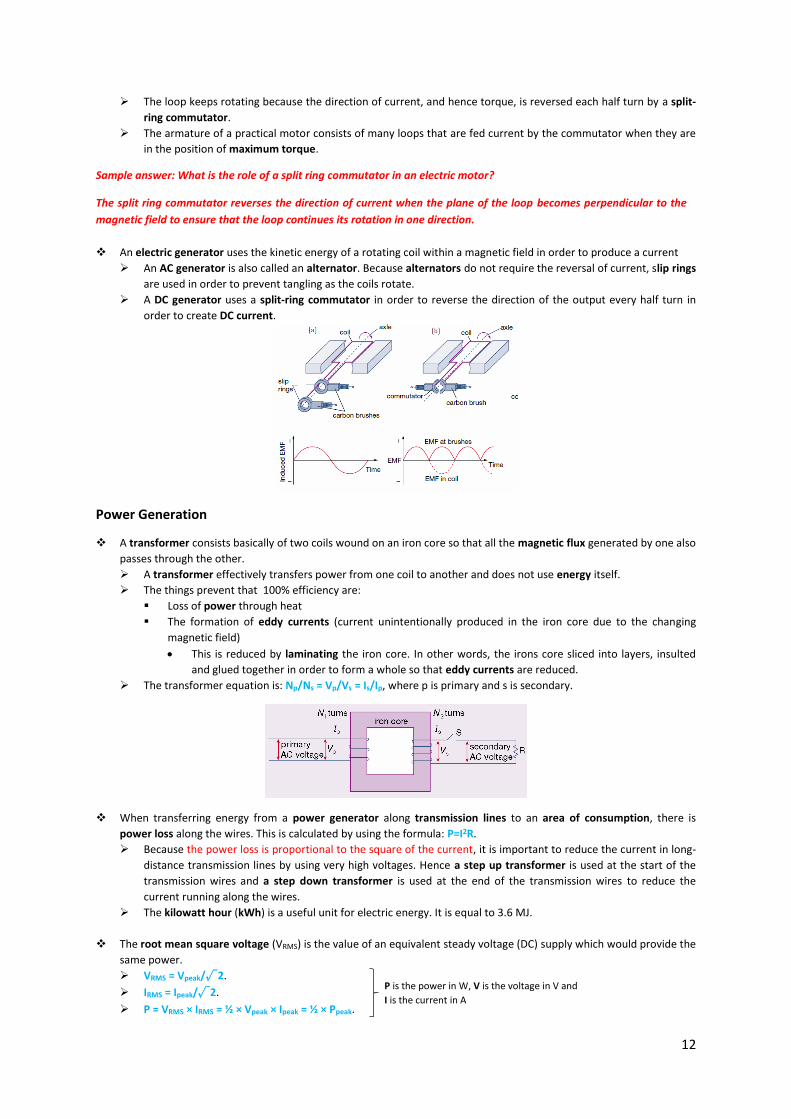
An electric generator uses the kinetic energy of a rotating coil within a magnetic field in order to produce a current
An AC generator is also called an alternator. Because alternators do not require the reversal of current, slip rings
are used in order to prevent tangling as the coils rotate.
A DC generator uses a split-ring commutator in order to reverse the direction of the output every half turn in
order to create DC current.
Power Generation
A transformer consists basically of two coils wound on an iron core so that all the magnetic flux generated by one also
passes through the other.
A transformer effectively transfers power from one coil to another and does not use energy itself.
The things prevent that 100% efficiency are:
Loss of power through heat
The formation of eddy currents (current unintentionally produced in the iron core due to the changing
magnetic field)
This is reduced by laminating the iron core. In other words, the irons core sliced into layers, insulted
and glued together in order to form a whole so that eddy currents are reduced.
The transformer equation is: Np/Ns = Vp/Vs = Is/Ip, where p is primary and s is secondary.
When transferring energy from a power generator along transmission lines to an area of consumption, there is
power loss along the wires. This is calculated by using the formula: P=I2R.
Because the power loss is proportional to the square of the current, it is important to reduce the current in long-
distance transmission lines by using very high voltages. Hence a step up transformer is used at the start of the
transmission wires and a step down transformer is used at the end of the transmission wires to reduce the
current running along the wires.
The kilowatt hour (kWh) is a useful unit for electric energy. It is equal to 3.6 MJ.
The root mean square voltage (VRMS) is the value of an equivalent steady voltage (DC) supply which would provide the
same power.
VRMS = Vpeak/√2.
IRMS = Ipeak/√2.
P = VRMS × IRMS = ½ × Vpeak × Ipeak = ½ × Ppeak.
P is the power in W, V is the voltage in V and
I is the current in A
13
Unit 4 - Area of Study Two: Interactions of Light and Matter
Introduction
In the past, the mysterious nature of light came from the fact that it did not fit any present model completely.
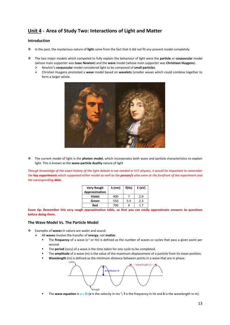
The two major models which competed to fully explain the behaviour of light were the particle or corpuscular model
(whose main supporter was Isaac Newton) and the wave model (whose main supporter was Christiaan Huygens).
Newton’s corpuscular model considered light to be composed of small particles.
Christian Huygens promoted a wave model based on wavelets (smaller waves which could combine together to
form a larger whole.
The current model of light is the photon model, which incorporates both wave and particle characteristics to explain
light. This is known as the wave-particle duality nature of light
Though knowledge of the exact history of the light debate is not needed in VCE physics, it would be important to remember
the key experiments which supported either model as well as the person/s who were at the forefront of the experiment and
the corresponding date.
Very Rough Approximation
λ (nm) f(Hz) E (eV)
Violet 400 7 2.9
Green 550 5.5 2.3
Red 700 4 1.7
Exam tip: Remember this very rough approximation table, so that you can easily approximate answers to questions
before doing them.
The Wave Model Vs. The Particle Model
Examples of waves in nature are water and sound.
All waves involve the transfer of energy, not matter.
The frequency of a wave (s-1 or Hz) is defined as the number of waves or cycles that pass a given point per
second.
The period (secs) of a wave is the time taken for one cycle to be completed.
The amplitude of a wave (m) is the value of the maximum displacement of a particle from its mean position.
Wavelength (m) is defined as the minimum distance between points in a wave that are in phase.
The wave equation is v = fλ (v is the velocity in ms–1, f is the frequency in Hz and λ is the wavelength in m).

14
The particular or corpuscular model that Newton proposed was based on how solid objects interacted with each
other (when defined by classical mechanics).
Particles have properties such as velocity, mass and, consequently, momentum.
Properties of Light That Can Only Be Defined by the Wave Model (Huygens)
Properties of Light That Can Only Be Defined by the Particle Model (Newton)
Diffraction The Absence of a Medium
Refraction The Photoelectric Effect
Beams Can Pass Through Each Other Without Interfering Momentum (i.e. Compton Scattering)
Polarisation
Interference Pattern Observed by the Single and Double-Slit Experiment
The Wave Model of Light in Depth
Diffraction is defined as the ability of waves to bend as they pass by an obstacle or through a gap (resulting in the
wave spreading out).
The extent of the diffraction is determined by the relative sizes of the wavelength, λ, and the obstacle or gap
diameter, w. The extent of diffraction of light ∝ wavelength slit size = λ/w.
If λ/w ≥ 1, then significant diffraction will be observed.
Even if the ratio is 0.8 or 0.9 (i.e. relatively close to one), then significant diffraction will be observed. The
ratio does not have to be larger than one for significant diffraction to be observed.
If λ/w << 1, then significant diffraction will not be observed.
In 1801, Young performed his famous double-slit experiment, which supported the wave model of light due to
various observations.
The doublet slit experiment was performed by isolating a single wavelength of light and projecting this
monochromatic light onto a screen through two slits. What resulted was a pattern, with not two bands of light as
expected but a series of dark and bright fringes or sections, i.e.
Not this:
But this:
15
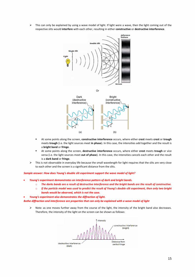
This can only be explained by using a wave model of light. If light were a wave, then the light coming out of the
respective slits would interfere with each other, resulting in either constructive or destructive interference.
Or
At some points along the screen, constructive interference occurs, where either crest meets crest or trough
meets trough (i.e. the light sources meet in phase). In this case, the intensities add together and the result is
a bright band or fringe.
At some points along the screen, destructive interference occurs, where either crest meets trough or vice
versa (i.e. the light sources meet out of phase). In this case, the intensities cancels each other and the result
is a dark band or fringe.
This is not observable in everyday life because the small wavelength for light requires that the slits are very close
to each other and the screen is a significant distance from the slits.
Sample answer: How does Young’s double slit experiment support the wave model of light?
Young’s experiment demonstrates an interference pattern of dark and bright bands.
o The darks bands are a result of destructive interference and the bright bands are the result of constructive.
o If the particle model was used to predict the result of Young’s double-slit experiment, then only two bright
bands would be observed, which is not the case.
Young’s experiment also demonstrates the diffraction of light.
Bothe diffraction and interference are properties that can only be explained with a wave model of light
Note: as one moves further away from the course of the light, the intensity of the bright band also decreases.
Therefore, the intensity of the light on the screen can be shown as follows:
16
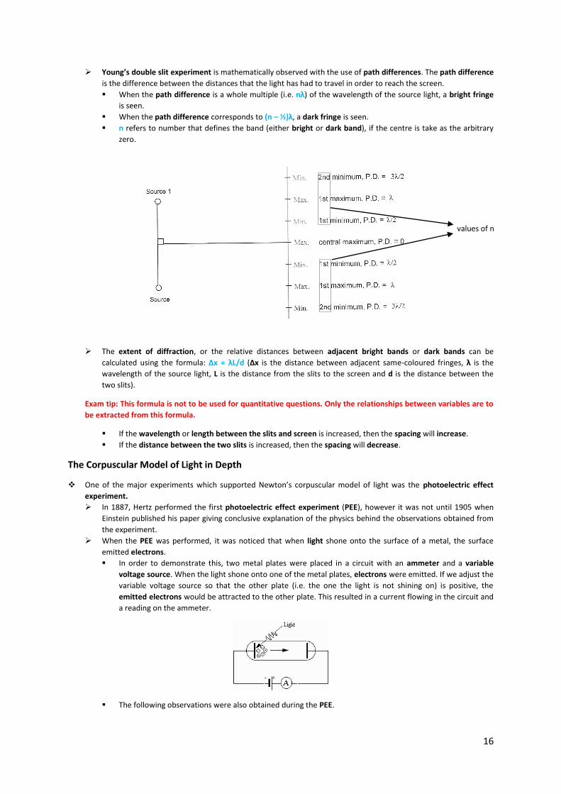
Young’s double slit experiment is mathematically observed with the use of path differences. The path difference
is the difference between the distances that the light has had to travel in order to reach the screen.
When the path difference is a whole multiple (i.e. nλ) of the wavelength of the source light, a bright fringe
is seen.
When the path difference corresponds to (n – ½)λ, a dark fringe is seen.
n refers to number that defines the band (either bright or dark band), if the centre is take as the arbitrary
zero.
The extent of diffraction, or the relative distances between adjacent bright bands or dark bands can be
calculated using the formula: ∆x = λL/d (∆x is the distance between adjacent same-coloured fringes, λ is the
wavelength of the source light, L is the distance from the slits to the screen and d is the distance between the
two slits).
Exam tip: This formula is not to be used for quantitative questions. Only the relationships between variables are to
be extracted from this formula.
If the wavelength or length between the slits and screen is increased, then the spacing will increase.
If the distance between the two slits is increased, then the spacing will decrease.
The Corpuscular Model of Light in Depth
One of the major experiments which supported Newton’s corpuscular model of light was the photoelectric effect
experiment.
In 1887, Hertz performed the first photoelectric effect experiment (PEE), however it was not until 1905 when
Einstein published his paper giving conclusive explanation of the physics behind the observations obtained from
the experiment.
When the PEE was performed, it was noticed that when light shone onto the surface of a metal, the surface
emitted electrons.
In order to demonstrate this, two metal plates were placed in a circuit with an ammeter and a variable
voltage source. When the light shone onto one of the metal plates, electrons were emitted. If we adjust the
variable voltage source so that the other plate (i.e. the one the light is not shining on) is positive, the
emitted electrons would be attracted to the other plate. This resulted in a current flowing in the circuit and
a reading on the ammeter.
The following observations were also obtained during the PEE.
values of n

17
The surface only emits electrons if the incident light is above a certain threshold frequency (f0). This
threshold frequency varied depending on the metal and is indicative of the binding energy required to
dislodge the electron from the metal surface.
The binding energy is also as the work function of a metal: W = hf0 (W is the work function of the
metal in J, h is Planck’s constant and f0 is the threshold frequency in Hz).
The rate of electron release (current) is proportional to the intensity of the light and occurs without
any time delay. The forward voltage does not affect the current.
If the voltage was reversed and slowly increased, there would be a point where the electrons no longer
reach the other metal plate. The reverse voltage at which this occurs is known as the stopping voltage
or Vc.
Because this stopping voltage is able to stop even the most energetic electrons from reaching the
other side, it is equivalent to the maximum kinetic energy (Ek max) of the photoelectrons: Vc = Ek max
Note: In this formula, the units of the kinetic energy is in electronvolts. The electronvolt is an
alternative (non-SI) unit of energy: 1 eV = 1.6 × 10⁻¹⁹ J.
The stopping voltage is influenced by the frequency of the incident light. If the frequency was
increased, so was the stopping voltage.
The fact that the wave model could not explain many of these observations (namely, the existence of a threshold
frequency, the absence of a time delay when using very weak light sources, and increased intensity of light
resulting in a greater rate of electron release rather than increased electron energy) meant that physicists sought
another model to explain the behaviour of light.

18
In 1905, Albert Einstein published a paper which used Max Planck’s photon model of light to explain the
photoelectric effect.
Planck’s work on light had resulted in a series of theories about the nature of light:
Light energy is quantised, that is it can only take up certain values that are multiples of an elementary
unit. In other words, light is made up of a stream of photons (which is ‘the elementary unit’).
The energy of a photon is directly proportional to its frequency: E = hf. The energy of a light beam is: E
= nhf (n being the number of photon in the light beam)
h, the constant of proportionality, is also known as Planck’s constant and is equal to 6.63 × 10⁻³⁴ J
s or 4.14 × 10⁻¹⁵ eV s
Only one photon can interact with one electron on the surface of metal at a time.
Einstein used the law of conservation of energy to show that if photoelectrons were released, the
maximum kinetic energy of these photoelectrons would come from the resulting energy the incident
photon had left after releasing the photoelectrons, that is: Ek max = hf – W = hf – hf0 (Ek max is the maximum
kinetic energy in J, h is Planck’s constant, f is the frequency in Hz, W is the work function and f0 is the
threshold frequency in Hz).
The photon (or particle-like) approach explained the existence of a threshold frequency for each metal, the
absence of a time delay for weak light sources and why brighter light resulted in a higher photocurrent.
Threshold frequency: Metal surfaces hold onto their surface electrons with a certain binding energy. This
energy, also known as the work function, must be overcome by the incident photon in order for the
electron to be dislodged. Since (as E = hf suggests) energy is proportional to frequency, there is a threshold
energy and corresponding threshold frequency of photon which will be able to release electrons from the
metal surface. The wave model would suggest that energy is accumulated as the brightness intensifies, so
light of any frequency should be able to produce photoelectrons, but this is not the case.
Time delay: The only requirement for photoelectrons to be released is that the frequency of light must be
higher than the threshold frequency. The wave model predicts a time delay, especially at low intensities of
light, for the energy to build up before photoelectrons are released. This is not observed.
Intensity α Current, not Stopping Voltage: Increasing the intensity of the light means increasing the number
of photons. This allows more photoelectrons to be released and, thereby, increasing the current produced.
This does not affect the stopping voltage as only the frequency of light affects the stopping voltage. The
wave model would suggest the energy of light is related to its intensity and therefore the intensity of the
incident light and the stopping voltage would be related. However, this is not the case.
Exam Tip: When asked to explain why a particular experiment either supported the wave or particle model, also
mention why it disproves the other model.
A graph of Ek max versus frequency will have a gradient equal to Planck’s constant, h, and a ‘y intercept’ equal to
the work function, W.
19
Another experiment which supported the particle model of light was the Compton scattering experiment, performed
in 1923.
In this experiment, Compton projected an X-ray beam into graphite. Some X-ray photons passed through the
graphite unaltered, but some photons were scattered with lower energies and simultaneously ejected an
electron.
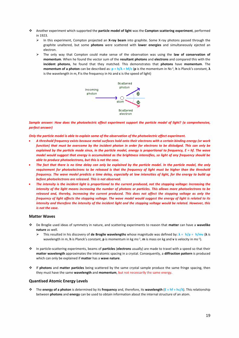
The only way that Compton could make sense of the observation was using the law of conservation of
momentum. When he found the vector sum of the resultant photons and electrons and compared this with the
incident photons, he found that they matched. This demonstrates that photons have momentum. The
momentum of a photon can be described as: p = h/λ = hf/c (p is the momentum in Ns-1, h is Planck’s constant, λ
is the wavelength in m, f is the frequency in Hz and c is the speed of light)
Sample answer: How does the photoelectric effect experiment support the particle model of light? (a comprehensive,
perfect answer)
Only the particle model is able to explain some of the observation of the photoelectric effect experiment.
A threshold frequency exists because metal surfaces hold onto their electrons with a certain binding energy (or work
function) that must be overcome by the incident photon in order for electrons to be dislodged. This can only be
explained by the particle mode since, in the particle model, energy is proportional to frequency, E = hf. The wave
model would suggest that energy is accumulated as the brightness intensifies, so light of any frequency should be
able to produce photoelectrons, but this is not the case.
The fact that there is no time delay can only be explained by the particle model. In the particle model, the only
requirement for photoelectrons to be released is that the frequency of light must be higher than the threshold
frequency. The wave model predicts a time delay, especially at low intensities of light, for the energy to build up
before photoelectrons are released. This is not observed.
The intensity is the incident light is proportional to the current produced, not the stopping voltage: Increasing the
intensity of the light means increasing the number of photons or particles. This allows more photoelectrons to be
released and, thereby, increasing the current produced. This does not affect the stopping voltage as only the
frequency of light affects the stopping voltage. The wave model would suggest the energy of light is related to its
intensity and therefore the intensity of the incident light and the stopping voltage would be related. However, this
is not the case.
Matter Waves
De Broglie used ideas of symmetry in nature, and scattering experiments to reason that matter can have a wavelike
nature as well.
This resulted in his discovery of de Broglie wavelengths whose magnitude was defined by: λ = h/p = h/mv (λ is
wavelength in m, h is Planck’s constant, p is momentum in kg ms-1, m is mass on kg and v is velocity in ms-1).
In particle-scattering experiments, beams of particles (electrons usually) are made to travel with a speed so that their
matter wavelength approximates the interatomic spacing in a crystal. Consequently, a diffraction pattern is produced
which can only be explained if matter has a wave nature.
If photons and matter particles being scattered by the same crystal sample produce the same fringe spacing, then
they must have the same wavelength and momentum, but not necessarily the same energy.
Quantised Atomic Energy Levels
The energy of a photon is determined by its frequency and, therefore, its wavelength (E = hf = hc/λ). This relationship
between photons and energy can be used to obtain information about the internal structure of an atom.

20
Atoms normally exist in their lowest energy state, known as the ground state. When energy is given to an atom, it will
move to a higher energy state.
The energy given to the atom must correspond to an exact difference in energy levels or else the atom will not
absorb it. In this way, electron energies within the atom are quantised, since only certain values are allowed.
There are two conventions of naming energy states:
The n-value is a counting system that starts at one when at the ground state and goes up a number as the
energy states climb higher.
The excitation level is simply the level number if the ground state is taken as the arbitrary zero.
A spectra is physical indication of a change in the energy state of an atom and is produced when light (and its energy)
is either absorbed or released by an atom.
An emission spectrum is produced by energised atoms dropping down to lower energy states.
An absorption spectrum is created when white light passes through a cold gas and the atoms move to a higher
energy state.
The energy of the photon either emitted or absorbed is given by: Ephoton = Em – En.
Where the electron starts in level n and drops to level m, the photon will be emitted.
Where the electron is promoted from the lower level m to the higher level n, the photon energy will be
absorbed.
Sample answer: Why are there more lines in an emission spectra than an absorption spectra?
An atom can only absorb energy that corresponds to a difference between its ground state and a higher energy state.
However, when energised, the atom will emit photons of energies that correspond to the difference between any energy
levels lower than the level it is currently at.
Standing Waves
De Broglie suggested that the only way that the electron could maintain a steady energy level was if it established a
standing wave, i.e. an exact multiple of its wavelength.
This is the reason electrons can only occupy particular energy levels in atoms.
The number of wavelengths in the standing waves is the n-value of the energy level.
The energy level on the left can be maintained as it fits an exact multiple of wavelengths and can be maintained. The energy level on the
right cannot fit an exact multiple of wavelength and will soon collapse on itself.
n-value
=
(n-1)th
excitation
value