physics notes for class 12 chapter 4 moving charges and ...ncerthelp.com/cbse notes/class...
TRANSCRIPT

1 | P a g e
www.ncerthelp.com (Visit for all ncert solutions in text and videos, CBSE syllabus, note and many more)
Physics Notes for Class 12 Chapter 4 Moving
Charges and Magnetrism
Oersted’s Experiment
A magnetic field is produced in the surrounding of any current carrying conductor.
The direction of this magnetic field can be obtained by Ampere’s swimming rule.
SI unit of magnetic field is Wm-2 or T (telsa).
The strength of magnetic field is called one tesla, if a charge of one coulomb, when moving
with a velocity of 1 ms-1 along a direction perpendicular to the direction of the magnetic field
experiences a force of one newton.
1 tesla (T) = 1 weber metre-2 (Wbm-2)
= 1 newton ampere-1 metre-1 (NA-1 m-1)
CGS units of magnetic field are called gauss or oersted.
1 gauss = 10-4 tesla.
Maxwell’s Cork Screw Rule
If a right handed cork screw is imagined to be rotated in such a direction that tip of the screw
points in the direction of the current, then direction of rotation of thumb gives the direction of
magnetic line of force.
The conventional sign for a magnetic field coming out of the plane and normal to it is a dot i.e.,
The magnetic field perpendicular to the plane in the downward action is denoted by ®.
Ampere’s Swimming Rule
If a man is swimming along the wire in the direction of current his face turned towards the
needle, so that the current enters through his feet, then north pole of the magnetic needle will
be deflected towards his left hand.
Magnetic Field
The space in the surrounding of a magnet or any current carrying conductor in which its
magnetic influence can be experienced.

2 | P a g e
www.ncerthelp.com (Visit for all ncert solutions in text and videos, CBSE syllabus, note and many more)
Biot Savart’s Law
The magnetic field produced by a current carrying element of length dl, carrying current I at a
point separated by a distance r is given by
dB = μo / 4 π Idl * r / r3
or dB = μo / 4 π Idl sin θ / r2
where, θ is the angle between the direction of the current and μo is absolute permeability of the
free space.
SI unit of magnetic field is Wm-2 or (tesla) and CGS unit of magnetic field is gauss or oersted 1
gauss = 10-4tesla.
The direction of magnetic field dB is that of I dl * r .
Magnetic Field Due to a Straight Current Carrying Conductor
where φ1 and φ2 are angles, which the lines joining the two ends of the conductor to the
observation point make with the perpendicular from the observation point to the conductor.
For infinite length conductor and observation point is near the centre of the conductor,

3 | P a g e
www.ncerthelp.com (Visit for all ncert solutions in text and videos, CBSE syllabus, note and many more)
B = μo / 4 π 2I / r
for infinite length conductor and observation point is near one end of the conductor,
B = μo / 4 π I / r
Magnetic Field Lines
They are used to res present magnetic B field in a region.
They are closed continuous curves.
Tangent drawn at any point gives the direction of magnetic field.
They cannot interact.
Outside a magnet, they are directed from north to south pole and inside a magnet they
are directed from south to north.
The magnetic field lines due to a straight current carrying conductor are concentric circles
having centre at conductor and in a plane perpendicular to the conductor.
The direction of magnetic field lines can be obtained by Right Hand Thumb Rule
Right Hand Thumb Rule

4 | P a g e
www.ncerthelp.com (Visit for all ncert solutions in text and videos, CBSE syllabus, note and many more)
If we hold a current carrying conductor in the grip of the right hand in such a way that thumb
points in the direction of current, then curling of fingers represents the direction of magnetic
field lines.
Magnetic Field on the Axis of a Current Carrying Circular Coil
Magnetic field at axis at a distance x from centre O.
where, r = radius of the coil, n = number of turns in the coil and I = current,
At centre of the coil, B = μo nl / 2 r
If we look at one face of the coil and the direction of current flowing through the coil is
clockwise, then that face has south polarity and if direction of current is anti-clockwise, then
that face has north polarity.
Magnetic Dipole
Every current carrying loop is a magnetic dipole. It has two poles south
(S) and north (N).
This is similar to a bar magnet.
Each magnetic dipole has some magnetic moment (M). The magnitude of M is,
5 | P a g e
www.ncerthelp.com (Visit for all ncert solutions in text and videos, CBSE syllabus, note and many more)
|M| = NiA
where, N = number of turns in the loop,
i = current in the loop and
A = area of cross-section of the loop.
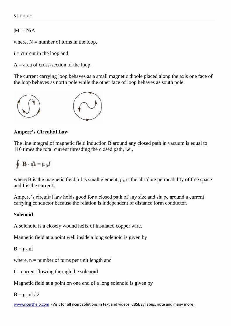
The current carrying loop behaves as a small magnetic dipole placed along the axis one face of
the loop behaves as north pole while the other face of loop behaves as south pole.
Ampere’s Circuital Law
The line integral of magnetic field induction B around any closed path in vacuum is equal to
110 times the total current threading the closed path, i.e.,
where B is the magnetic field, dl is small element, μo is the absolute permeability of free space
and I is the current.
Ampere’s circuital law holds good for a closed path of any size and shape around a current
carrying conductor because the relation is independent of distance form conductor.
Solenoid
A solenoid is a closely wound helix of insulated copper wire.
Magnetic field at a point well inside a long solenoid is given by
B = μo nl
where, n = number of turns per unit length and
I = current flowing through the solenoid
Magnetic field at a point on one end of a long solenoid is given by
B = μo nl / 2

6 | P a g e
www.ncerthelp.com (Visit for all ncert solutions in text and videos, CBSE syllabus, note and many more)
Toroid
A toroidal solenoid is an anchor ring around which is large number of turns of a copper wire
are wrapped.
A toroid is an endless solenoid in the form of a ring.
Magnetic field inside the turns of toroid is given by
B = μo nl
Magnetic field inside a toroid is constant and is always tangential to the circular closed path.
Magnetic field at any point inside the empty space surrounded by the toroid and outside the
toroid, is zero, because net current enclosed by these space is zero.
Magnetic Field Due to a Current Carrying Long Circular Cylinder
Outside the cylinder (r > R)
B = μ / 2 π l / r
Inside the cylinder when it is made of a thin metal sheet,
B = O
Inside the cylinder when current is uniformly distributed throughout the cross-section of the
cylinder (r < R)
B = μo μr / 2 π Ir / R2
where, μo and μr are permeabilities of free space and material of the cylinder, I is current
flowing through the cylinder and r is radius of the cylinder.
Force Acting on a Charge Particle Moving in a Uniform Magnetic Field
F = q(v * B)
or F = |F| = Bqv sin θ

7 | P a g e
www.ncerthelp.com (Visit for all ncert solutions in text and videos, CBSE syllabus, note and many more)
where, B = magnetic field intensity,
q = charge on particle,
u = speed of the particle and
θ = angle between magnetic field and direction of motion.
This force is perpendicular to B as well as v.
Its direction can be obtained from Fleming’s left hand rule.
Magnetic force acting on a current carrying conductor in a uniform magnetic field is given by
F = I ( I * B)
Fleming’s left Hand Rule
If we stretch the thumb, the forefinger and the central finger if left hand in such a way that all
three are perpendicular to each other, then if forefinger represents the direction of magnetic
field, central finger represents the direction of current flowing through the conductor, then
thumb will represent the direction of magnetic force.
Lorentz Force

8 | P a g e
www.ncerthelp.com (Visit for all ncert solutions in text and videos, CBSE syllabus, note and many more)
The total force experienced by a charge moving inside the electric and magnetic fields is called
Lorentz force. It is given by F = q(E * v * B)
Motion of a Charged Particle in a Uniform Magnetic Field
When charged particle enter normal to the magnetic field it follows a circular path.
The radius of the path, r = mv / Bq
∴ r ∝ mv
and r ∝ 1 / (q / m)
Time period, T = 2πm / Bq
When charged particle enter magnetic field at any angle except 90°, then it follows helical path.
The radius of the path, r = mv sin θ / Bq
The distance travelled by the charged particle in one time period due to component of velocity
v cos θ, is called pitch of the path
Pitch = T * v cos θ = 2πmv cos θ / Bq
Cyclotron
Cyclotron is a device used to accelerate positively charged particles such as proton, deuteron
etc.
Principle of Cyclotron
A positively charged particle can be accelerated through a modera. electric field by crossing it
again and again by use of strong magnetic field.
Radius of circular path, r = mv / Bq
Cyclotron frequency v = Bq / 2πm
where m and q are mass and charge of the positive ion and B is strength of the magnetic field.
Maximum kinetic energy gained by the particle.
Emax = B2q2r2o / 2m
where, ro = maximum radius of circular path.

9 | P a g e
www.ncerthelp.com (Visit for all ncert solutions in text and videos, CBSE syllabus, note and many more)
When a positive ion is accelerated by the cyclotron, it moves with greater and greater speed. As
the speed of ion becomes comparable with that of light, the mass of the ion increases according
to the relation.
Where, m = mass of the lOD.
mo = maximum mass of the ion.
v = speed of Ion and
c = speed of light.
Limitations of the Cyclotron
(i) Cyclotron cannot accelerated uncharged particle like neutron.
(ii) The positively charged particles having large mass i.e., ions cannot move at limitless speed
in a cyclotron.
Force between Two Infinitely Long Parallel Current Carrying Conductors

10 | P a g e
www.ncerthelp.com (Visit for all ncert solutions in text and videos, CBSE syllabus, note and many more)
The force is attractive if current In both conductors is in same direction and repulsive if current
10 both conductors is in opposite direction.
(if the currents is both parallel wires arc equal and In same direction, then magnetic field at a
point exactly half way between the wire is zero.)
Torque acting on a Current Carrying Coil Placed Inside a Uniform Magnetic Field
Torque acting on a current carrying coil placed inside a uniform magnetic field is given
τ = NBIA sin θ
Where, N = number of turns in the coil,
E = magnetic field intensity,
I = current 10 the coil and
A = area of cross-section of the coil,
θ = angle between magnetic field and normal to the plane of the coil.
Moving Coil Galvanometer
It is a device used for the detection and measurement of the currents.
In equilibrium, deflecting torque = restoring torque

11 | P a g e
www.ncerthelp.com (Visit for all ncert solutions in text and videos, CBSE syllabus, note and many more)
where, k = restoring torque per unit twist,
N = number of turns in the coil,
B = magnetic field intensity,
A = area of cross-section of the coil and
θ = angle of twist.
Current Sensitivity
The deflection produced per unit current in galvanometer is called its current sensitivity.
Current sensitivity
Is = θ / I = NBA / K
Voltage Sensitivity
The deflection produced per unit voltage applied across the ends of galvanometer is called its
voltage sensitivity.
Voltage sensitivity
Vs = θ / V = NBA / KR
where R is the resistance of the galvanometer.

12 | P a g e
www.ncerthelp.com (Visit for all ncert solutions in text and videos, CBSE syllabus, note and many more)
Therefore for a sensitive galvanometer
(i) N should be large
(ii) B should be large
(iii) A should be large
(iv) K should be small
Ammeter
An ammeter is a low resistance galvanometer used for measuring the current in a circuit.
It is always connected in series.
Conversion of a Galvanometer into an Ammeter
A galvanometer can be converted into an ammeter by connecting a low resistance into its
parallel.
If G is the resistance of a galvanometer and it give full scale deflection for current, Ig then
required low resistance S, connected in its parallel for converting it into an ammeter of range I
is given by
The resistance of an ideal ammeter is zero.
Voltmeter
A voltmeter is a high resistance galvanometer used for measuring the potential difference
between two points.
It is always connected in parallel.
The resistance of an ideal voltmeter is infinity.

13 | P a g e
www.ncerthelp.com (Visit for all ncert solutions in text and videos, CBSE syllabus, note and many more)
Conversion of a Galvanometer into a Voltmeter
A galvanometer can be converted into a voltmeter by connecting a high resistance into its
series.
If a galvanometer of resistance G show full scale deflection for current Ig then required high
resistance R, connected in series for converting it into a voltmeter of range V is given by