physics lecture notes (simple circuits 2011)€¦ · lecture notes (simple circuits) intro: - it is...
TRANSCRIPT
Lecture Notes (Simple Circuits)
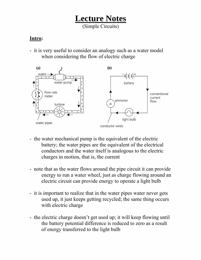
Intro: - it is very useful to consider an analogy such as a water model when considering the flow of electric charge
- the water mechanical pump is the equivalent of the electric battery; the water pipes are the equivalent of the electrical conductors and the water itself is analogous to the electric charges in motion, that is, the current - note that as the water flows around the pipe circuit it can provide energy to run a water wheel, just as charge flowing around an electric circuit can provide energy to operate a light bulb - it is important to realize that in the water pipes water never gets used up, it just keeps getting recycled; the same thing occurs with electric charge - the electric charge doesn’t get used up; it will keep flowing until the battery potential difference is reduced to zero as a result of energy transferred to the light bulb

- an electric circuit must be a complete closed loop path; in this case, the charges flow from the battery through the conductors to the light bulb and deliver the energy given to them by the battery - if the path is not complete, charge will not flow and the current stops; this is called an open circuit - if the battery terminals are connected directly together without the circuit containing a device such as a light bulb to restrict the amount of charge flowing, then a short circuit occurs
- this is a very dangerous situation as the very large current that may flow can cause heating of the conductors, and subsequent fires - in fact, it is possible to cause sparking and welding of the metal conductors when very large batteries are short-circuited Diagramming Circuits: - you can describe a circuit by using words as well as visually by the use of symbols and drawings

- a set of standard symbols has been devised to diagram electric circuits; drawings using these symbols is called a schematic
- rules for drawing a schematic are as follows:
1) Draw the battery or other source of electric energy on the left side of the page
2) Draw a wire coming out of the positive terminal; when you reach a resistor draw the symbol for it
3) At points of two multiple current paths, use a dot to signify the joining of multiple paths of current
4) Follow the current path until you reach the negative terminal of the battery or other source of energy

Series Circuits: - a series circuit is the simplest circuit; the conductors, resistors, and power source are connected with only one path for current
- the resistance of each device can be different; the same amount of current will flow through each; the voltage across will be different - if the path is broken, no current will flow - an ammeter is a device used to measure the current through a device
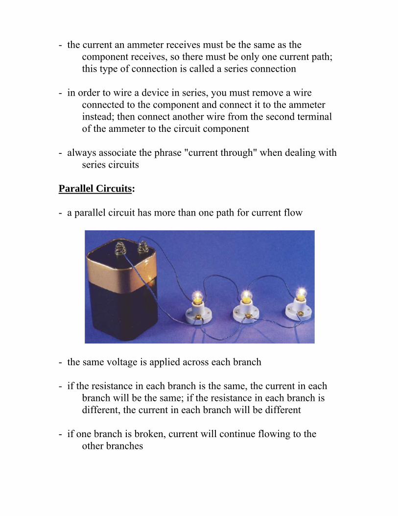
- the current an ammeter receives must be the same as the component receives, so there must be only one current path; this type of connection is called a series connection - in order to wire a device in series, you must remove a wire connected to the component and connect it to the ammeter instead; then connect another wire from the second terminal of the ammeter to the circuit component - always associate the phrase "current through" when dealing with series circuits Parallel Circuits: - a parallel circuit has more than one path for current flow
- the same voltage is applied across each branch - if the resistance in each branch is the same, the current in each branch will be the same; if the resistance in each branch is different, the current in each branch will be different - if one branch is broken, current will continue flowing to the other branches

- a voltmeter is a device used to measure the potential difference between two points
- when connecting a voltmeter to a circuit always connect the positive terminal to the end of the circuit component closer to the positive end of the battery - then connect the other terminal to the other side of the component - this type of connection is called a parallel connection because the circuit component and the voltmeter are aligned parallel to each other - in this type of setup, the potential difference across the voltmeter is identical to that across the circuit component - always associate the phrase "voltage across" when dealing with parallel circuit - voltage makes circuits "go"; currents flow in a circuit because they are given a path from high voltage to low voltage

- voltages are always measured with respect to some reference point in a circuit; sometimes we refer to “voltage drop” or “voltage difference” between two points; other times, we give the voltage with respect to a reference point called “ground”, (usually the negative terminal of the battery) - along any wire (or other good conductor), the voltage is a constant; voltage drops occur across components, such as resistors Series-Parallel Circuits: - a series-parallel circuit has some components in series and others in parallel - the power source and control or protection devices are usually in series; the resistors are usually in parallel - the same current flows in the series portion, while different currents flow in the parallel portion - the same voltage is applied to the parallel devices, different voltages to series devices - if the series portion is broken, current stops flowing in the entire circuit; if a parallel branch is broken, current continues flowing in the series section and the remaining parallel branches Resistance in a Series Circuit: - a series circuit is formed when any number of resistors are connected end to end so that there is only one path for current to flow - the resistors can be actual resistors or other devices that have resistance; the illustration below shows four resistors connected end to end

- there is one path of current flow from the positive terminal of the battery through R1, R2, R3, R4 returning to the negative terminal
- the values of resistance add in a series circuit; Ex. if a 4 Ω resistor is placed in series with a 6 Ω resistor, the total resistance will be 10 Ω - this is true when other types of resistive devices are placed in series - the mathematical formula for resistance in series is:
Rt = R1 + R2 + R3 + ... Given a series circuit where R1 is 11 kΩ, R2 is 2 kΩ, R3 is 2 kΩ, R4 is 100 Ω, and R5 is 1 kΩ, what is the total resistance?
Rt = R1 + R2 + R3 + R4 + R5 Rt = 11,000 Ω + 2,000 Ω + 2,000 Ω + 100 Ω + 1,000 Ω Rt = 16,100 Ω Current in a Series Circuits: - the equation for total resistance in a series circuit allows us to simplify a circuit

- using Ohm's law, the value of current can be calculated - current is the same anywhere it is measured in a series circuit Ex. What is the current in a circuit where four resistors are
connected in series. The resistors have resistances of 5 Ω, 1 Ω, 2 Ω, and 2 Ω.
12 V 1.2 A10
VI I IR
Voltage in a Series Circuits: - voltage can be measured across each of the resistors in a circuit; the voltage across a resistor is referred to as a voltage drop - a German physicist, Kirchoff, formulated a law which states that the sum of the voltage drops across the resistances of a closed circuit equals the total voltage applied to the circuit Ex. In the following illustration below, we have four equal
resistors of 1.5 Ω each placed in series with a 12 V battery; Ohm's law can be applied to show that each resistor will "drop" an equal amount of voltage

- solve the problem with the following steps:
1) Solve for the total resistance Rt = R1 + R2 + R3 + R4 Rt = 1.5 Ω + 1.5 Ω + 1.5 Ω + 1.5 Ω Rt = 6 Ω
2) Solve for current
12 V 2 A6
VI I IR
3) Solve for voltage across any resistor V = IR V = 2 A × 1.5 Ω V = 3 V
- if voltage were measured across any single resistor, a voltmeter would read 3 V; if voltage were read across a combination of resistors R3 and R4, a voltmeter would read 6 V; if voltage were read across a combination of resistors R2, R3 and R4, a voltmeter would read 9 V; if voltage were read across a combination of resistors R1, R2, R3 and R4, a voltmeter would read 12 V (the original supply voltage of the battery)

Series Circuit Review:
Resistance in a Parallel Circuit: - a parallel circuit is formed when two or more resistances are placed in a circuit side by side so that current can flow through more than one path - the diagram below shows two resistors side by side; there are two paths of current flow
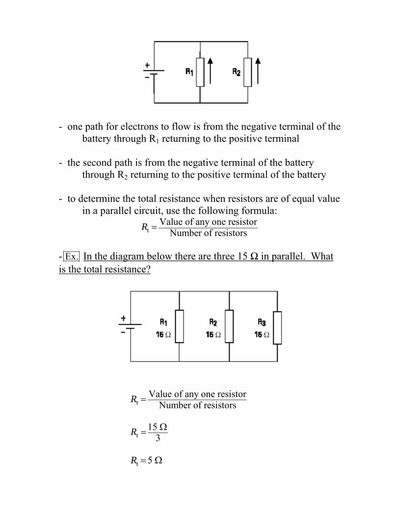
- one path for electrons to flow is from the negative terminal of the battery through R1 returning to the positive terminal - the second path is from the negative terminal of the battery through R2 returning to the positive terminal of the battery - to determine the total resistance when resistors are of equal value in a parallel circuit, use the following formula:
tValue of any one resistor
Number of resistorsR
- Ex. In the diagram below there are three 15 Ω in parallel. What is the total resistance?
tValue of any one resistor
Number of resistorsR
t15
3R
t 5 R

- remember, the above equation is only valid for times when all the resistors in a parallel circuit are equal - if you have a parallel circuit with resistors of different resistances, use the following formula:
t 1 2 3
1 1 1 1 ...R R R R
- Ex. In the following diagram below, there are three resistors in parallel, each with a different value. If the three resistors have resistances of 5 Ω, 10 Ω, and 20 Ω what is the total resistance of the circuit?
t 1 2 3
1 1 1 1 ...R R R R
t
1 1 1 15 10 20 R
t
1 720 R
t 20 1 7R t 2.86 R

Voltage in a Parallel Circuit: - when resistors are placed in parallel across a voltage source, the voltage is the same across each resistor - in the diagram below, we have a circuit with three resistors placed in parallel across a 12 volt battery; each resistor has 12 V available to it
Current in a Parallel Circuit: - current flowing through a parallel circuit divides and flows through each branch of the circuit
- total current in a parallel circuit is equal to the sum of the current in each branch; the following mathematical formula applies to current in a parallel circuit:
It = I1 + I2 + I3 + ... - when equal resistances are placed in a parallel circuit, opposition to current flow is the same in each branch

- Ex. In the diagram below, R1 and R2 are of equal value. If total current is 10 amps, then 5 A would flow through R1 and 5 A would flow through R2.
It = I1 + I2 It = 5 A + 5 A It = 10 A - with unequal resistances placed in a parallel circuit, opposition to current flow is not the same in each circuit branch - current flow will be greater through the path of least resistance - Ex. In the diagram below, R1 is 40 Ω and R2 is 20 Ω. If the voltage supplied is 12 volts, then what is the current flowing through each branch?

1 2 1 21 2
1 2
1 2
12V 12V 0.3A 0.6A40 20
0.3A 0.6A 0.9A
t
t
t
V VI I I I IR R
I I I
I I I
- the total current can also be found by finding the total resistance and then using Ohm's law Parallel Circuit Review:
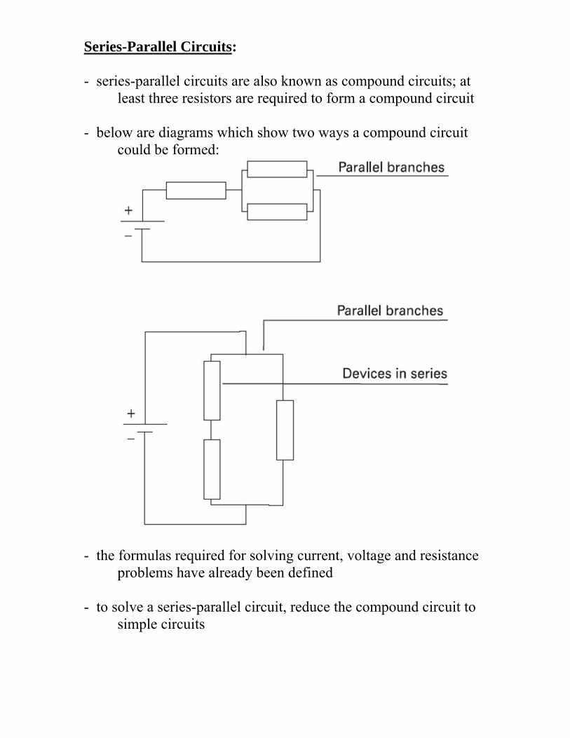
Series-Parallel Circuits: - series-parallel circuits are also known as compound circuits; at least three resistors are required to form a compound circuit - below are diagrams which show two ways a compound circuit could be formed:
- the formulas required for solving current, voltage and resistance problems have already been defined - to solve a series-parallel circuit, reduce the compound circuit to simple circuits
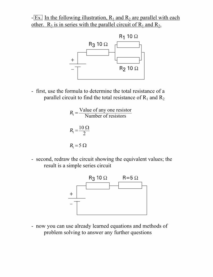
- Ex. In the following illustration, R1 and R2 are parallel with each other. R3 is in series with the parallel circuit of R1 and R2.
- first, use the formula to determine the total resistance of a parallel circuit to find the total resistance of R1 and R2
tValue of any one resistor
Number of resistorsR
t10
2R
t 5 R - second, redraw the circuit showing the equivalent values; the result is a simple series circuit
- now you can use already learned equations and methods of problem solving to answer any further questions

- Ex. In the following diagram, R1 and R2 are in series with each other. R3 is in parallel with the series circuit of R1 and R2.
- first use the formula to determine total resistance of R1 and R2. Rt = R1 + R2 Rt = 10 Ω + 10 Ω Rt = 20 Ω - second, redraw the circuit showing the equivalent values; the result is a simple parallel circuit which uses already learned equations and methods of problem solving

Series-Parallel Circuit Review: