physics 332: e&m 2013 inductionbulldog2.redlands.edu/facultyfolder/eric_hill...physics 332:...
TRANSCRIPT

Physics 332: E&M 2013 Induction
Fri., 11/1 7.1.3-7.2.2 Emf & Induction
Mon. 11/4
Wed., 11/6
Fri., 11/8
Exam 2 (Ch 3 & 5)
7.2.3-7.2.5 Inductance and Energy of B
7.3.1-.3.3 Maxwell’s Equations
Equipment:
o Crank generator
o Cow magnet and copper pipe
o Eddy current demo: magnet and swinging fins – with and without fingers
o Homemade electric motor
o Two of our old induction coils
Last Time
Ohm’s Law
EJ tyconductivi
R
VI
EMF
df
Motional emf
Example 7.4 – Faraday’s Disk
A metal disk of radius a rotates with an angular frequency (counterclockwise
viewed from above) about an axis parallel to a uniform magnetic field. A circuit is
made by a sliding contact. What is the current through the resistor R?
Note: This problem cannot be solved using
d dt .
Find the emf by calculating the line integral of the force per charge from the center to
the contact point. The speed of a point at a distance s from the center is
v s, so the
force per charge is
f mag v B sB ˆ s . The emf is
f mag d fmagds0
a
B s ds0
a
Ba2
2.
The current found using Ohm’s law is
I
RBa2
2R.

2
By the RHR, it flows from the center to the outer edge of the disk.
Phrasing in terms of Magnetic Flux
Let’s return to the original result for the emf. It can be rephrased a bit. Here, we are
changing the area of a loop through which the field is flowing.
dt
d
dt
BAd
dt
dABBvLemf B
If we impose the Right Hand Rule for sign conventions, we’d have
dt
demf B
Problem 7.11
A square loop is cut out of a thick sheet of aluminum. It is placed so that the top
portion is in a uniform, horizontal magnetic field of 1 T into the page (as shown
below) and allowed to fall under gravity. The shading indicates the field region. What
is the terminal velocity of the loop? How long does it take to reach 90% of the
terminal velocity?
Use y for the distance from the bottom of the field region. The magnetic flux is
yB , so the size of the emf is
d
dt B v .
By Ohm’s law, the size of the current is
I RB v R. By the RHR, the current
flows in the direction of
v B (for the top segment), which is to the right.
The magnetic field is perpendicular to the current in the loop so the force is
F I d B I B B2 2v
R,
where
is the length of a side. By the RHR, the direction of
d B and the force on
the loop is to the upward. This is a 1-D problem. Using downward as positive,
Newton’s second law is
mgB2 2
Rv ma m
dv
dt.
Terminal “velocity” is reached when the acceleration is zero, so
mgB2 2
Rv 0 vt
mgR
B2 2.
The equation of motion can be written as

3
gB2 2
mRv 1
v
vt
g
dv
dt.
This can be integrated to get (starts from rest):
dv
v t v
g
v t
dt ,
dv
vt v 0
v t
g
vt
dt0
t
,
ln vt v 0
v
lnvt v
vt
gt
vt
,
v t v
vt
egt vt v v t 1 egt vt .
At 90% of terminal velocity,
v
vt
0.9 1 egt vt egt vt 0.1,
gt vt ln 1 10 t vt
gln 10 .
Suppose the cross sectional area is A. The mass is
m 4 A , where
2.7103kg/m3 is the mass density of aluminum. The resistance of the loop is
R 4 A 4 A , where
2.8108m is the resistivity of aluminum. The
terminal velocity is
vt mgR
B2 2
4A g 4 A B2 2
16g
B2,
so the time to reach 90% of terminal velocity is
t vt
gln 10
16
B2ln 10
16 2.7103kg/m3 2.8108m 1 T
2 2.8103s 2.8 ms.
The units work because ohm = V/A and T = N/(Am).
Phrasing in terms of Magnetic Flux
B
Bmotion
temf
4
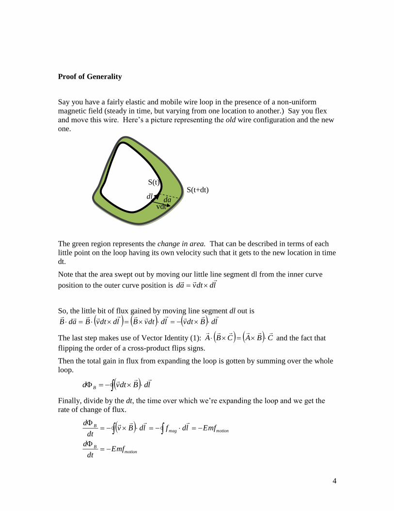
Proof of Generality
Say you have a fairly elastic and mobile wire loop in the presence of a non-uniform
magnetic field (steady in time, but varying from one location to another.) Say you flex
and move this wire. Here’s a picture representing the old wire configuration and the new
one.
The green region represents the change in area. That can be described in terms of each
little point on the loop having its own velocity such that it gets to the new location in time
dt.
Note that the area swept out by moving our little line segment dl from the inner curve
position to the outer curve position is lddtvad
So, the little bit of flux gained by moving line segment dl out is
ldBdtvlddtvBlddtvBadB
The last step makes use of Vector Identity (1): CBACBA
and the fact that
flipping the order of a cross-product flips signs.
Then the total gain in flux from expanding the loop is gotten by summing over the whole
loop.
ldBdtvd B
Finally, divide by the dt, the time over which we’re expanding the loop and we get the
rate of change of flux.
motionB
motionmagB
Emfdt
d
EmfldfldBvdt
d
vdt
S(t) S(t+dt)
dl da
5
In slightly better mathematical notation, since we’re holding something constant (the
field) over time, this is the partial derivative
B
Bmotion
temf
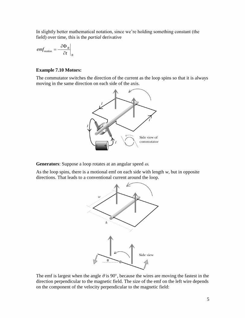
Example 7.10 Motors:
The commutator switches the direction of the current as the loop spins so that it is always
moving in the same direction on each side of the axis.
Generators: Suppose a loop rotates at an angular speed .
As the loop spins, there is a motional emf on each side with length w, but in opposite
directions. That leads to a conventional current around the loop.
The emf is largest when the angle is 90, because the wires are moving the fastest in the
direction perpendicular to the magnetic field. The size of the emf on the left wire depends
on the component of the velocity perpendicular to the magnetic field:

6
sinsin
cosemf left BA
dt
dBA
dt
BAd
dt
ABd
dt
d
.
Faraday’s Law
So, we actually derived
d
dt for motional emf – when the charges are moving
relative to the magnetic field, but what about if the field is moving relative to the
charges? On the one hand, isn’t motion just a relative thing? When we see a wire
moving in a field doesn’t it see the field moving? Either way you look at it, a current
should get flowing around the wire. So shouldn’t there again be some kind of force
per charge, some kind of emf? On the other hand, the way we’ve defined the
magnetic interaction (the one that depends upon the motion of the sensing charge) we
can’t call that interaction ‘magnetic.’
So, as we’ve reasoned
d
dt
Holds not just if the area is changing, but if the field is changing too. That
observation is called Faraday’s Law. To be particularly specific about it,
a
Fdt
d
That is, the Faraday effect is that there’s an emf generated when the flux changes due
to the magnetic field changing (the area remaining constant.) Either (or both) way
you cut it, there’s an emf.
aB
Fmotiontt
dt
d
Faraday’s contribution, a
Ft
, can be rephrased if we dig into our definitions
of emf and flux:
adt
Bad
q
F
adBt
ldq
F
t
a
a
F

7
Where we used Stoke’s theorem on the left and the fact that we’re holding the area
constant on the right.
Of course, if the two integrals are the same, then the two integrands must be the same,
so
t
B
q
F
What is this force? Well, process of elimination leaves Electric as the only candidate
– it isn’t magnetic since we defined magnetism as the thing that depends on the
sensing charge’s velocity (and we’re imagining keeping those steady), and there are
no other players than the charges – so this must be the charge-charge force that
doesn’t depend on sensor velocity; that is, electric.
t
BE
t
B
q
Eq
I will speak a little more carefully than Griffiths does at this point,
A changing magnetic field is accompanied by an electric field.
Misnomer Warning: I do not say “induces” because that word implies “causes” and
many physicists (even Griffiths later in this section) mistakenly make that connection.
This law here is not a causal one; it is a correlation – there’s no way to deduce form it
whether E’s curl causes B’s time variation or the other way around, or neither. The
correct answer is “neither.” Both are caused by time-varying current densities; we’ll
see the proof of that in Ch. 10.
adt
Bad
q
F
adBt
ldq
F
t
a
a
F
At any rate, this is a very powerful deductive tool, and we can phrase it a few
different ways:
t
BE
(note: direction of E’s circulation is opposite to the direction
of change in flux, i.e., use a left hand rule to grab the change
in flux and see the direction of E.)
ad
t
BldE
(note: similarity to Ampere’s Law)

8
a
Ft
In any of these equivalent forms, it’s called Faraday’s Law.
In both cases (varying area or field), the size of the emf is equal to the rate of change of
the magnetic flux. Some situations can be seen as one or the other effect depending on
the reference frame – but there is not always one frame that works for all parts of the
circuit, so that more generally only works locally.
Several ways to change the Magnetic Flux:
Exercise – Come up with ways to change the magnetic flux through a coil using either a
second coil or a permanent magnet
All of the following will result in an induced emf in the coil 2 on the right.
1. Change the current in coil 1
I1 increasing
B 1 inc reasing
2. Move coil 1 (with current through it)
v 1
B 1 inc reasing
3. Move coil 2 (with current through coil 1)
v 2
B 1 4. Rotate coil 1
B 1
Rotate coil 2
B 1 5. Move the magnet relative to the coil (includes moving coil toward magnet)

9
v 1
B 1 inc reasing
N S
6. Rotate the magnet
B 1
N
S
7. Rotate the coil
B 1
N S
Problem 7.14
Explain why a cylindrical magnet takes much longer to drop through a vertical copper
pipe than an unmagnetized piece of iron does.
(Ignore the part about the “current in the magnet”)
Demo: drop a magnet down a copper tube (not ferromagnetic) –very slow compared to
free fall!
Each cross section of the pipe can be considered a loop. There will be induced currents
around the pipe. These in turn produce magnetic fields, so it’s like having two magnets
interact. You will explain the slowing in terms of forces in Prob. 22.1 (c).
Lenz’s Law
We usually just used Faraday’s law to find the magnitude of the emf and don’t worry
about the minus sign. Lenz’s law can be used to determine the direction of the
induced current. It states that, “Nature abhors a change in magnetic flux.” In other

10
words, the induced current will produce a magnetic field that will somewhat oppose
the change in flux.
Apply this to the figures above.
Examples
Pr. 7.12
Example 7.7 (an Ampere’s Law type approach)
Pr. 7.15 dt
dldE B
ndatIadB oB )(
Problem 7.16 – Coaxial Cable with Change Current
An (slowly) alternating current
I t I0 cost flows down a long, straight, thin wire
and returns along a thin, coaxial conducting tube of radius a.
a. In what direction does the induced electrical field point?
Let the current on the central wire be in the +z direction. In the quasistatic
approximation (current changes slowly), the magnetic field is circumferential. A
changing magnetic field in this direction is analogous to the current for a solenoid,
which produces a longitudinal (in z direction) magnetic field. Therefore, the
direction of the induced electric field is longitudinal.
b. Assuming that the field goes to zero as
s, find the induced electric field
E s, t .
The magnetic field in the quasistatic approximation is (use Ampere’s law)
B
0I
2sˆ s a,
0 s a.
By symmetry, we also know that the induced electric field only s (and t). Use the
same shape of “amperian loop” as for a solenoid (see the diagram below).

11
a
s
Stretch this side to show
that E is zero out here.
z
r
dr
We can argue that the induced electric field is the same at all distances outside the
coaxial cable, so it must be zero (use the loop on the left).
For a loop with one side inside the cable (on the right), the line integral of the electric
field around the loop is
E d E , because only the bottom side is non-zero.
Consider a thin strip between distances r and r + dr from the long wire that is enclosed by
the loop. The magnetic flux through this segment is
d0I
2r
dr .
The magnetic field comes out of the page, so the flux is positive by the RHR. The
total flux through the loop is
0I
2
dr
rs
a
0I
2ln r
s
a0I
2ln
a
s
.
Putting in the function for the current and applying Faraday’s law,
E d d dt, gives
E s, t
0I0
2ln
a
s
sin t ˆ z s a,
0 s a.
Pr. 7.17 dt
demfIR B
(use Lenz’s Law for direction)

12
"After equation 7.17 ("Faraday's Law") Griffiths mentions that this is actually determined by both magnetic and electric field. The second of which is 'caused' by mag field why does the third experiment work out the same as the first two?" Casey P,
Also I noticed an interesting author in footnote [8]... ;) Casey P,
Yes, I don't suppose you have a copy of said discussion mentioned... Casey McGrath
"I put this in the questions last time, but since we didn't quite get to it, I still don't really understand all of the mechanics leading up to how he derived equation 7.13, which is pretty crucial to the rest of these sections." Casey McGrath
Also, maybe I'm just missing something, but how did he make the jump from 7.14 to
7.15? Was that just an observational argument as stated in the prior sentence, or did
he derive that using some other equation? Casey McGrath
I may be able to help. Flux is area hx*B through it. Induced EMF should change in
field through over change in time. Also -Bhv = - Bh (dx/dt). That gives 7.13.
For 7.14-7.15 Flux is also the B field through an area, so it makes sense that change
in flux would make sense for change in flux to turn into dB(dot)da.
I don't know if that's what you needed but I hope it helps.Anton
"I don't understand why Griffith does not consider Experiment 1 to be an example of Faraday's law."Davies
"Griffiths was mentioning how Faraday's Law breaks down when we talk about induction. I'm not sure I understand his discussion of quasistatic magnetic fields soonafter." Rachael Hach
"This might not be a big plot point but I was curious as to why exactly in example 7.9 the use of the quasistatic approximation would cause E to blow up."Ben Kid
I think it has to do with the definition of the speed of light, in which B depends on the
current as it was earlier. The quasistatic approximation assumes that at any distance
the information of the system travels instantly, but with relativity this is not true.Davies
"How is the emf different than the change in voltage? Is there a reason why we redefine it as the emf? Also, can we do some sketches of emf vs. time tomorrow (Figure 7.23)?"Spencer
My understanding so far, emf is more of a measure of a result than the cause. So a
change in voltage would cause an emf, but the changes in magnetic fields also
cause emf, but not voltage. I'm not sure though, this is just a thought.Freeman,
"I'm not sure if i understand example 7.8. Its kinda confusing how they got some of the equations they used."Connor W,

13