physics 170 lecture 6 chapter 3 - particle equilibrium ...mattison/courses/phys170/p170-6.pdf ·...
TRANSCRIPT

Phys 170 Lecture 6 1
Physics 170 Lecture 6
Chapter 3 - Particle Equilibrium
Free Body DiagramsSpecial Forces
Equilibrium Condition

Free Body Diagrams
1. Identify the object of interest2. Enclose the object in a contour3. Draw a vector for every force that enters the contour (including gravity, and possibly electric & magnetic force)
Phys 170 Lecture 6 2

Special ForcesWeight
Direction is down (–y in 2D, –z in 3D)Magnitude is mg, g = 9.81 N/kg (or m/s2) in metricMagnitude is pounds (lb) in US (mass is slugs, not pounds!)
Normal Force (objects touch but not really connected)Direction is at right angles to surface (or its tangent if curved)Magnitude is unknown, must be calculated
Static Friction Force (objects touch as above, but don’t slide)Magnitude is unknown, except , must be calc’dDirection is parallel to surface but can be either direction!![Dynamic (sliding) friction has definite magnitude and has definite direction (opposite to the velocity)]
Phys 170 Lecture 6 3
!W
F < µstaticN
!N
!F
F = µdynN
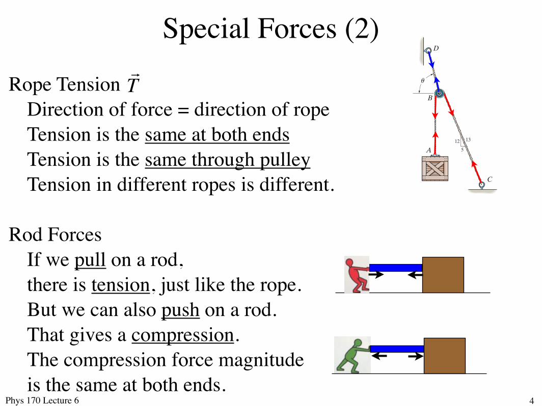
Special Forces (2)
Rope TensionDirection of force = direction of ropeTension is the same at both endsTension is the same through pulleyTension in different ropes is different.
Rod ForcesIf we pull on a rod, there is tension, just like the rope.But we can also push on a rod. That gives a compression.The compression force magnitude is the same at both ends.
Phys 170 Lecture 6 4
!T
3
3.3 COPLANAR FORCE SYSTEMS 99
3–7. The man attempts to pull down the tree using the cable and small pulley arrangement shown. If the tension in AB is 60 lb, determine the tension in cable CAD and the angle u which the cable makes at the pulley.
20!
B
A
C
D
30!
u
Prob. 3–7
*3–8. The cords ABC and BD can each support a maximum load of 100 lb. Determine the maximum weight of the crate, and the angle u for equilibrium.
12
5
13
B
A
C
D
u
Prob. 3–8
3–9. Determine the maximum force F that can be supported in the position shown if each chain can support a maximum tension of 600 lb before it fails.
CA
B
4 5
3
30!
F
Prob. 3–9
3–10. The block has a weight of 20 lb and is being hoisted at uniform velocity. Determine the angle u for equilibrium and the force in cord AB.
3–11. Determine the maximum weight W of the block that can be suspended in the position shown if cords AB and CAD can each support a maximum tension of 80 lb. Also, what is the angle u for equilibrium?
B
F
20! A
C
Du
Probs. 3–10/11

Special Forces (3)
DON’T assume that the ONLY forceof a rigid rod is parallel to the rod! If that were true, then an engine hoist wouldn’t work!
Forces perpendicular to rods areshear-forces.
But, if the rod has hinges or ball-and-socket joints at both ends, and no other forces on it, then it will rotate until the force in the rod is a pure compression or tension.
The hydraulic cylinder in the engine hoist is an example.Phys 170 Lecture 6 5

Phys 170 Lecture 6 6

Special Forces (4)
Spring Force Spring has a spring constant k and an unstretched length L0.
Force on spring is proportional to change in length:
Force by spring tries to restore its unstretched length.
We will only do problems where the spring stays straight due to hinges etc, so the force direction is along the spring.[Bending a spring gives other forces we won’t deal with....]
Phys 170 Lecture 6 7
!F
F = k L ! L0( ) = ks
88 CHAPTER 3 EQUIL IBR IUM OF A PART ICLE
3
3.2 The Free-Body Diagram
To apply the equation of equilibrium, we must account for all the known and unknown forces (!F) which act on the particle. The best way to do this is to think of the particle as isolated and “free” from its surroundings. A drawing that shows the particle with all the forces that act on it is called a free-body diagram (FBD).
Before presenting a formal procedure as to how to draw a free-body diagram, we will first consider three types of supports often encountered in particle equilibrium problems.
Springs. If a linearly elastic spring (or cord) of undeformed length l0 is used to support a particle, the length of the spring will change in direct proportion to the force F acting on it, Fig. 3–1a. A characteristic that defines the “elasticity” of a spring is the spring constant or stiffness k.
The magnitude of force exerted on a linearly elastic spring which has a stiffness k and is deformed (elongated or compressed) a distance s = l - l0, measured from its unloaded position, is
F = ks (3–2)
If s is positive, causing an elongation, then F must pull on the spring; whereas if s is negative, causing a shortening, then F must push on it. For example, if the spring in Fig. 3–1a has an unstretched length of 0.8 m and a stiffness k = 500 N>m and it is stretched to a length of 1 m, so that s = l - l0 = 1 m - 0.8 m = 0.2 m, then a force F = ks = 500 N>m(0.2 m) = 100 N is needed.
Cables and Pulleys. Unless otherwise stated throughout this book, except in Sec. 7.4, all cables (or cords) will be assumed to have negligible weight and they cannot stretch. Also, a cable can support only a tension or “pulling” force, and this force always acts in the direction of the cable. In Chapter 5, it will be shown that the tension force developed in a continuous cable which passes over a frictionless pulley must have a constant magnitude to keep the cable in equilibrium. Hence, for any angle u, shown in Fig. 3–1b, the cable is subjected to a constant tension T throughout its length.
Smooth Contact. If an object rests on a smooth surface, then the surface will exert a force on the object that is normal to the surface at the point of contact. An example of this is shown in Fig. 3–2a. In addition to this normal force N, the cylinder is also subjected to its weight W and the force T of the cord. Since these three forces are concurrent at the center of the cylinder, Fig. 3–2b, we can apply the equation of equilibrium to this “particle,” which is the same as applying it to the cylinder.
F
!s
l
l0
T
T
u
Fig. 3–1
T
WN
T
30!30!
20!
20!
(a) (b)
Fig. 3–2
Cable is in tension
(a)
(b)
L0L
Forceon spring
Forceby spring

FBD Example
The man with weight W1 stands at thecenter of the uniform plank with weight W2
Draw the free body diagram for the plank.Neglect friction at ends of board,but not friction of the man on the board.
Phys 170 Lecture 6 8
!N1
!W2
!NA
!NB
!T
!F1
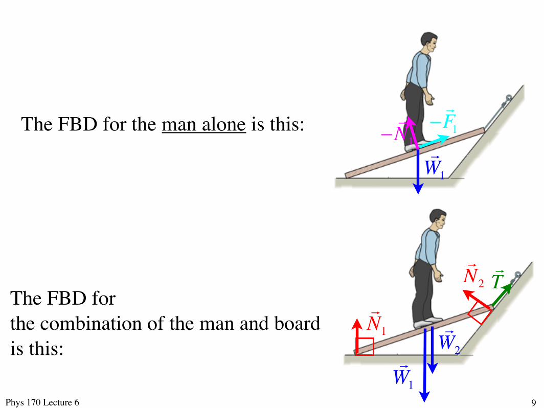
The FBD for the combination of the man and board is this:
Phys 170 Lecture 6 9 !W1
!W2
!N1
!N2 !T
!!F1
!!N1
!W1
The FBD for the man alone is this:

Equilibrium Condition
The common meaning of equilibrium is the absence of motion, and that’s what it will almost always mean in Phys 170.
Because Newton insists that , if the total force is non-zero, we get acceleration, meaning motion. So equilibrium requires that the sum of all force vectors must be zero.
It’s usually best to write this as one equation per component
Phys 170 Lecture 6 10
!F = m!a
!F1 +!F2 +
!F3 + .... = 0
F1X + F2X + F3X + .... = 0F1Y + F2Y + F3Y + .... = 0F1Z + F2Z + F3Z + .... = 0

Solving Problems
Since we have 3 equations, we can solve for 3 unknowns.
The simplest case is all 3 components of one vector unknown, and all other vectors known. Each equation has one unknown.
We could also have 3 unknown magnitudes, but all directions known. Each equation has 3 unknowns. But they are linear, which means they can be solved with a $20 calculator.
If the unknown is an angle, the equations are non-linear.But you can usually change to unknown components,which makes the equations linear. Calculate the angle at end.
Phys 170 Lecture 6 11

Phys 170 Lecture 6 12

Solution
Phys 170 Lecture 6 13
!P +!F1 +!F2 +
!F3 = 0!
!P = "(
!F1 +!F2 +
!F3 )
!F1 = 2kN cos 45°
!i + cos60°
!j + cos120°
!k( )
= 1.4142!i +1.0000
!j !1.0000
!k
!F2 = 0.75kN !1.5
!i + 3!j + 3!k
1.52 + 32 + 32=
0.754.5
!1.5!i + 3!j + 3!k( )
= !0.2500!i + 0.5000
!j + 0.5000
!k
!F3 = 0
!i ! 0.5
!j + 0!k
PX = ! 1.4142 ! 0.2500 + 0( ) = !1.1642PY = ! 1.0000 + 0.5000 ! 0.5000( ) = !1.0000PY = ! !1.0000 + 0.5000 + 0( ) = +0.5000

Solution
Phys 170 Lecture 6 14
PX = ! 1.4142 ! 0.2500 + 0( ) = !1.1642PY = ! 1.0000 + 0.5000 ! 0.5000( ) = !1.0000PY = ! !1.0000 + 0.5000 + 0( ) = +0.5000!P = 1.16422 +12 + 0.52 = 1.6141 kN
" = cos!1 !1.16421.6141
= 136.07°
# = cos!1 !1.00001.6141
= 128.28°
$ = cos!1 0.50001.6141
= 71.95°

Phys 170 Lecture 6 15
3-43 (page 109, 13th edition)
COMPLETION OF PROBLEM (page 1):
FORCES AND EQUATIONS OF EQUILIBRIUM
• Forces (suppressing units)
!P = P
x
!i +P
y
!j +P
z
!k
!F1= 2(cos45"
!i + cos60"
!j + cos120"
!k)
!F2= (!1.5
!i + 3!j + 3!k) A A = 0.75 / 1.52+32+32
!F3= 0.5
!j
• Equations of equilibrium
!FR= F
Rx
!i +F
Ry
!j +F
Rz
!k = 0
FRx
= ! Fx= 0:
Px+2cos45!!1.5A = 0
FRy= ! F
y= 0:
Py+2cos60!+ 3A!0.5 = 0
FRz= ! F
z= 0:
Pz+2cos120!+ 3A = 0

Phys 170 Lecture 6 16
3-43 (page 109, 13th edition)
COMPLETION OF PROBLEM (page 2):
SOLVING THE EQUATIONS OF EQUILIBRIUM
• Solve for Px, P
y, P
z:
Px= !2cos45!+1.5A = B
Py= !2cos60!! 3A+0.5 = C
Pz= 2cos120!! 3A = D
• Magnitude and coordinate direction angles:
P = Px2+Py
2+Pz
2 = B
2+C
2+D
2= 1.61 kN
!P= cos"1(P
x/P)
= cos!1(B /P) = 136!
!P= cos"1(P
y/P)
= cos!1(C /P) = 128!
!P= cos"1(P
z/P)
= cos!1(D /P) = 72.0!

Phys 170 Lecture 6 33
Calculator Vector Instructions

Phys 170 Lecture 6 18

Phys 170 Lecture 6 19
For Next Time
Read all of Chapter 3
Read Chapter 4 sections 1-3Moments in 2D (several ways to do it)Cross product of vectorsMoments in 3D (almost always using cross product)
Homework assignments 1+2 due Friday.
Practice problems & tutorials available (optional, no points)