physical properties of hydrate bearing sediments.pdf
TRANSCRIPT
PHYSICAL PROPERTIES OF HYDRATE-BEARING
SEDIMENTS
W. F. Waite,1 J. C. Santamarina,2 D. D. Cortes,2 B. Dugan,3 D. N. Espinoza,2 J. Germaine,4
J. Jang,2 J. W. Jung,2 T. J. Kneafsey,5 H. Shin,2 K. Soga,6 W. J. Winters,1 and T.-S. Yun7
Received 1 December 2008; revised 18 June 2009; accepted 14 July 2009; published 31 December 2009.
[1] Methane gas hydrates, crystalline inclusion compoundsformed from methane and water, are found in marinecontinental margin and permafrost sediments worldwide.This article reviews the current understanding ofphenomena involved in gas hydrate formation and thephysical properties of hydrate-bearing sediments. Formationphenomena include pore-scale habit, solubility, spatialvariability, and host sediment aggregate properties. Physicalproperties include thermal properties, permeability, electricalconductivity and permittivity, small-strain elastic P and Swave velocities, shear strength, and volume changes
resulting from hydrate dissociation. The magnitudes andinterdependencies of these properties are critically importantfor predicting and quantifying macroscale responses ofhydrate-bearing sediments to changes in mechanical,thermal, or chemical boundary conditions. Thesepredictions are vital for mitigating borehole, local, andregional slope stability hazards; optimizing recoverytechniques for extracting methane from hydrate-bearingsediments or sequestering carbon dioxide in gas hydrate;and evaluating the role of gas hydrate in the global carboncycle.
Citation: Waite, W. F., et al. (2009), Physical properties of hydrate-bearing sediments, Rev. Geophys., 47, RG4003,
doi:10.1029/2008RG000279.
Table of Contents
1. Introduction..................................................................... 2
1.1. Exploration .............................................................. 2
1.2. Production................................................................ 2
1.3. Reservoir Management............................................ 2
2. Solubility of Hydrate-Forming Gas
in Aqueous Systems ....................................................... 3
2.1. Theoretical Determination of Solubility
Concentrations......................................................... 3
2.2. Data .......................................................................... 4
2.3. Geologic Implications .............................................. 5
3. Hydrate Formation in Sediment ...................................... 5
3.1. Hydrate in Pores....................................................... 6
3.2. Hydrate Formation in the Laboratory ...................... 6
3.3. Hydrate Formation in Nature ................................... 7
3.4. Laboratory Formation of Analog Hydrate ............... 7
4. Spatial Variability............................................................ 8
5. Sampling and Handling Effects ...................................... 8
5.1. Hydrate-Free Sediments........................................... 8
5.2. Hydrate-Bearing Sediments ..................................... 9
6. Sediment Index Properties ............................................ 10
6.1. Hydrate Saturation and Distribution ...................... 10
6.2. Phenomena During Production .............................. 11
6.3. Estimation of Design Parameters ........................... 11
7. Thermal Properties ........................................................ 11
7.1. Thermal Conductivity, l ........................................ 127.2. Specific Heat, cp..................................................... 13
7.3. Thermal Diffusivity, k............................................ 137.4. Enthalpy of Reaction, DH ..................................... 14
8. Permeability and Fluid Migration ................................. 14
8.1. Single-Phase Fluid Flow ........................................ 14
8.2. Multiphase Fluid Flow........................................... 15
8.3. Fluid Flow in Hydrate-Bearing Systems................ 16
9. Electromagnetic Properties ........................................... 16
9.1. Electrical Conductivity of Hydrate-Bearing
Sediments .............................................................. 17
9.2. Permittivity of Hydrate-Bearing Sediments ........... 17
9.3. Field-Based Characterization of
Hydrate-Bearing Sediments: Limitations .............. 18
10. Seismic Wave Velocity, Attenuation,
and Small-Strain Stiffness ........................................... 18
10.1. Wave Velocities.................................................... 19
10.2. Attenuation........................................................... 20
1U.S. Geological Survey, Woods Hole, Massachusetts, USA.2School of Civil and Environmental Engineering, Georgia Institute of
Technology, Atlanta, Georgia, USA.3Department of Earth Science, Rice University, Houston, Texas, USA.4Department of Civil and Environmental Engineering, Massachusetts
Institute of Technology, Cambridge, Massachusetts, USA.
5Lawrence Berkeley National Laboratory, Berkeley, California, USA.6Department of Engineering, University of Cambridge, Cambridge,
UK.7School of Civil and Environmental Engineering, Yonsei University,
Seoul, South Korea.
Copyright 2009 by the American Geophysical Union.
8755-1209/09/2008RG000279
Reviews of Geophysics, 47, RG4003 / 2009
1 of 38
Paper number 2008RG000279
RG4003

11. Strength and Deformation ........................................... 21
11.1. Definition of Strength and Deformation
Parameters ............................................................ 21
11.2. Laboratory Measurements.................................... 21
11.3. General Trends ..................................................... 22
12. Volume Change Upon Dissociation ............................ 24
12.1. Contraction due to Bulk Hydrate
Dissociation .......................................................... 25
12.2. Contraction due to Disseminated Hydrate
Dissociation.......................................................... 25
1. INTRODUCTION
[2] Gas hydrates are crystalline clathrates composed of
low molecular weight gases, the most common of which is
methane, encaged in a lattice of hydrogen-bonded water
molecules. Methane gas hydrate, found beneath permafrost
and in marine continental margin sediments worldwide
[Kvenvolden and Lorenson, 2001], is the most common
naturally occurring gas hydrate and has attracted interest as
a possible energy resource [Collett, 2002; Dallimore and
Collett, 2005; Grauls, 2001; Holder et al., 1984; Ruppel,
2007] and as a potential agent in climate change [Archer,
2007; Dickens et al., 1995; Ruppel and Pohlman, 2008] and
seafloor instability [Kayen and Lee, 1991, 1993; McIver,
1982; Mienert et al., 2005; Nixon and Grozic, 2007].
[3] Gas hydrate research, as measured by publication
numbers, has grown exponentially through the 20th century
[Sloan, 2004]. Much of the measurement work has focused
on gas hydrate as a pure material, referred to here as
‘‘hydrate,’’ and has been comprehensively reviewed by
Sloan and Koh [2008]. As research shifts to hydrates in
sediments, it is appropriate to review the current under-
standing of the evolution, behavior, and physical properties
of hydrate-bearing sediments.
[4] Consider the process of methane recovery from
hydrate-bearing sediments, discussed in sections 1.1–1.3
in terms of the critical roles physical properties play in the
exploration, production, and reservoir management phases.
Sections of this paper that address the corresponding
governing parameters are given in parentheses.
1.1. Exploration
[5] Host sediment properties (section 6), particularly
sediment grain size, play a prominent role in evaluating
sites for their resource potential. Exploration for hydrate as
an energy resource focuses on sands rather than fine-grained
material to facilitate extraction while minimizing technical
production challenges [Boswell and Collett, 2006; JIP Leg
II Science Team, 2009]. A ‘‘petroleum systems’’ approach
has been adopted to target sands with high hydrate satu-
rations [Hutchinson et al., 2008; Jones et al., 2008]. One
component of this approach is to identify sands that are
linked to a methane source (section 2) via faults or other
permeable pathways [Frye, 2008].
[6] Migration pathways and general reservoir properties
(section 4) can be identified from seismic or other remote
sensing data [Hutchinson et al., 2008; Jones et al., 2008].
These mapping techniques rely on the effects of hydrates on
sediment properties relative to hydrate-free sediment. Elec-
trical survey data are sensitive to the resistivity increase as
hydrate replaces conductive pore water in the sediment
(section 9) [Weitemeyer et al., 2006], whereas seismic
survey data are sensitive to the increase in wave velocity
that hydrate imparts to the host sediment (section 10) [Dai
et al., 2008b].
[7] The extent to which a given volume of hydrate alters
the host sediment properties depends on where hydrate
forms within the pore space (section 3) [Dvorkin et al.,
2000]. Careful consideration must therefore be given in
laboratory studies when mimicking hydrate-bearing sedi-
ments, when linking pore space hydrate saturations to
measured physical properties (section 5), and when inter-
preting field data [Dai et al., 2008b].
1.2. Production
[8] Hydrate dissociation during drilling or production
reduces the volume of a solid phase in the formation and
converts it into a mixed fluid phase that is several times
larger in volume, with immediate implications for fluid
pressure, effective stress [Rutqvist et al., 2008], strength
(section 11), and volumetric deformation (section 12)
[Kwon et al., 2008]. Potential implications include the
collapse of the production borehole [Birchwood et al.,
2008]. Strength loss due to hydrate dissociation must also
be considered while producing conventional hydrocarbons
underlying hydrate-bearing strata as relatively warm hydro-
carbons pumped through hydrate-bearing layers can desta-
bilize hydrate surrounding the production well [Briaud and
Chaouch, 1997; Hadley et al., 2008].
1.3. Reservoir Management
[9] The economical viability of a reservoir depends on a
combination of several factors such as thermal properties,
formation permeability, and sediment spatial variability. The
rate at which dissociation can occur, for instance, is limited
by the reservoir temperature and ability to conduct the heat
needed to drive the endothermic dissociation of gas hydrate
(section 7) [Anderson et al., 2008; Kneafsey et al., 2007].
The formation permeability and the relative permeability in
the presence of gas and water (section 8) determine the ease
with which methane can be transported into the production
well [Sakamoto et al., 2008]. Sediment properties (section
12.3. Contraction due to Increased Effective Stress:
Depressurization................................................... 25
12.4. Contraction due to Mineral Migration and
Removal ............................................................... 26
12.5. Additional Consequences of Volume
Contraction........................................................... 26
13. Future Research Directions in the Characterization
of Hydrate-Bearing Sediments .................................... 26
Notation............................................................................. 27
RG4003 Waite et al.: PHYSICAL PROPERTIES OF HYDRATE-BEARING SEDIMENTS
2 of 38
RG4003

6) determine other production-related processes, such as
fines migration during the production and clogging of
permeable pathways around the production well [Valdes
and Santamarina, 2007; Walsh et al., 2009]. Reservoir
models used to optimize recovery strategies and forecast
the economic potential of a given hydrate reservoir must
properly account for interdependencies between physical
properties in order to reliably capture the inherently coupled
hydromechanical, thermomechanical, and chemomechani-
cal processes that govern the behavior of hydrate-bearing
sediment [Anderson et al., 2008; Walsh et al., 2009; Wilder
et al., 2008].
[10] The production example given in section 1.2 is not
merely hypothetical. The Chevron–Department of Energy
(DOE) Joint Industry Project (JIP) in the Gulf of Mexico
completed a drilling program in May 2009 to test whether
the ‘‘petroleum system’’ approach mentioned in section 1.1
is applicable to locating sand units with high hydrate
saturations [JIP Leg II Science Team, 2009]. On Alaska’s
North Slope, a ConocoPhillips–DOE JIP is planning a
long-term production test from a subpermafrost hydrate-
bearing sand [ConocoPhillips –University of Bergen
Hydrates Team, 2008]. Several countries are currently
exploring for hydrate-bearing reservoirs [Expert Panel on
Gas Hydrates, 2008], and Japan aims to produce methane
from hydrate at a commercial scale by 2016 [Sakamoto et
al., 2008].
[11] In support of ongoing efforts in hydrate exploration,
reservoir assessment, analyses of gas hydrate’s role in
climate change, and evaluation of seafloor instability con-
ditions, this review collects the current understanding of
physical properties of hydrate-bearing sediment. Where
possible, connections are made between these properties
to indicate the ways in which hydrate-bearing sediment
evolves in response to changes in its surroundings.
2. SOLUBILITY OF HYDRATE-FORMING GAS INAQUEOUS SYSTEMS
[12] Hydrate forms in the presence of water when there is
enough hydrate-forming gas and both pressure and temper-
ature are conducive to hydrate stability. Conversely, the
hydrate crystal may break down and release methane by
either dissolution, when there is not enough hydrate-form-
ing gas in the surrounding water, or dissociation, when the
pressure and temperature requirements for stability are not
met. Whereas hydrate dissolution results in only a small net
volume increase [Lu et al., 2008; Sultan et al., 2004a],
dissociation generates a free methane gas phase and a much
larger volume increase [Kwon et al., 2008; Xu and Germa-
novich, 2006].
[13] The equilibrium concentration of hydrate-forming
gas (the solute) in the surrounding water or aqueous system
(the solvent) is given in units of molarity, M, defined as
moles of solute per liter of solution. Solute concentration
can also be given in terms of molality, m, defined as the
moles of solute per kilogram of solvent. For simplicity, the
solute considered herein is methane, CH4.
[14] Dissolution and precipitation occur when hydrate is
in contact with water. During dissolution, hydrate dissolves
into the water phase, increasing the methane concentration
in the water. During precipitation, hydrate formation
extracts methane from the water phase, lowering the meth-
ane concentration in the water. In the presence of hydrate,
dissolution and precipitation occur at the same rate when the
concentration of methane in the water reaches the solubility
limit. In the absence of hydrate, methane molecules move at
equal rates between the free gas phase and the dissolved
phase when the concentration of methane in water reaches
the solubility limit (Figure 1).
2.1. Theoretical Determination of SolubilityConcentrations
[15] The solubility of each chemical species in the
gaseous, liquid, and hydrate phases can be calculated from
thermodynamic properties by minimizing the system’s
Gibbs free energy or, equivalently, equating the potential
energy changes in the system, as shown in Table 1 [Sun and
Duan, 2007; Zatsepina and Buffett, 1998]. In step 3 in Table
1, the Trebble and Bishnoi [1987] equation of state has been
shown to work well for the methane-water system [Englezos
and Bishnoi, 1988; Zatsepina and Buffett, 1998]. Solubility
can also be estimated directly from fugacity-based models,
Figure 1. Solubility curves for methane in water withhydrate (solid curve) and without hydrate (dashed curve).Pressure is assumed constant at 12 MPa. Depending on thetemperature, a solution with excess methane will eitherprecipitate hydrate or push methane into the gas phase (topschematics) until the methane concentration falls to thesolubility value. A solution with a methane deficit willdissolve hydrate or absorb free gas (bottom schematics)until the solution’s methane concentration rises to thesolubility value. When methane is entering and exiting thesolution at equal rates, the system is in dynamic equilibriumat the solubility concentration.
RG4003 Waite et al.: PHYSICAL PROPERTIES OF HYDRATE-BEARING SEDIMENTS
3 of 38
RG4003

though expressions for activity and fugacity can be complex
when the combined effects of temperature, pressure, salin-
ity, and pore size are included. Solubility ‘‘calculators’’ that
account for some of these effects can be found online
(http://www.geochem-model.org/?page_id=48) [Duan and
Mao, 2006; Sun and Duan, 2007].
2.2. Data
[16] Experimental measurements and theoretical esti-
mates for methane solubility in water with and without
hydrate are compiled in Tables 2a–2c. Here we summarize
the dependence of methane solubility in water on temper-
ature, pressure, salinity, capillary pressure, and pore size.
2.2.1. Temperature[17] The solubility of methane in water is primarily
controlled by temperature and the presence of hydrate. In
the absence of hydrate (dashed curve in Figure 1), methane
becomes less soluble as the temperature increases because
the increasing kinetic energy allows molecules to break
intermolecular bonds in the liquid water and move into the
gas phase. The same general concept applies in the presence
of hydrate, where increasing temperature means more
energetic methane molecules can break out of the solid
hydrate and enter the liquid water, increasing the water’s
methane concentration (solid curve in Figure 1) [Subrama-
nian and Sloan, 2002].
2.2.2. Pressure[18] In the absence of hydrate, the solubility rises with
increasing pressure, indicating an increased preference for
methane to exist in the dissolved phase rather than the gas
phase [Servio and Englezos, 2002]. In the presence of
hydrate, solubility falls slightly with increasing pressure,
indicating a preference for methane to exist in the hydrate
rather than the water phase [Lu et al., 2008].
2.2.3. Salinity[19] The addition of salt drives methane out of solution,
shifting the curves in Figure 1 to lower values. Methane is
forced into hydrate if it is present or into the gas phase in the
absence of hydrate [Davie et al., 2004; Sun and Duan,
2007; Tishchenko et al., 2005; Zatsepina and Buffett, 1998].
Solubility changes due to salt are secondary to those of
temperature in natural settings but are important in flow
assurance applications, such as preventing hydrate forma-
tion in pipelines, where electrolytes and other chemical
inhibitors are used extensively [Sloan and Koh, 2008].
2.2.4. Capillary Pressure and Pore Size[20] Capillary pressure is the pressure difference across
an interface between two immiscible phases, such as water
and hydrate or water and gas. The capillary pressure, DP,
across a spherical interface of radius r and interfacial
tension gi,w between species i (hydrate or free methane
gas in this case) and water is
DP ¼ Pi � Pw ¼ gi;w2
r
� �: ð1Þ
The pressure, Pi, in the hydrate or free gas bubble is
therefore higher than the pressure in the water, Pw, by an
amount equal to the capillary pressure, DP. Equation (1)
indicates that the capillary pressure increases with decreas-
ing radius of interfacial curvature.
[21] Like the capillary pressure, the chemical potential in
a hydrate crystal or free gas bubble scales inversely with the
radius of curvature [Clennell et al., 1999]. Smaller hydrate
crystals or free gas bubbles therefore have higher chemical
potentials than their larger counterparts and require higher
methane concentrations in the surrounding water to balance
that chemical potential [Henry et al., 1999; Kwon et al.,
2008]. This process is only significant in small pores, which
would need to have radii <18 nm for this solubility increase
TABLE 1. Obtaining the Equilibrium Solubility Concentration, xij, of Species i in Phase j FromMinimizing Gibbs Free Energy,Ga
Step Process Equation
1 minimize Gibbs free energy, G, or equate chemical potentials, m G =Pi;jnijmi
j or DmwH = mw
b � mwH = mw
b � mwL = Dmw
L
2 relate chemical potential to activity, a, or fugacity, f mij - mi
0 + RT � ln(aij) = mi0 + RT � ln f
j
i
f 0i
� �3 relate activity or fugacity to concentration, x ai
j =fj
i
f 0i
= nijxi
j
aNotation is as follows: n is number of moles; mij is chemical potential or free energy per mole of species i in phase j, with j = 0 representing a convenient
reference state; activity, a, is a measure of how nonideal molecules such as methane and water interact; fugacity, f, is a measure of how stable a species is ina given phase; ideal gas constant R = 8.314 J (mol K)�1; T is temperature in kelvins; and n is the activity coefficient determined from an equation of state.Subscript w refers to water. Superscripts H, b, and L refer to water in the hydrate phase, in a hypothetical empty hydrate with no guest molecules, and in theliquid phase, respectively.
TABLE 2A. Solubility References for Hydrate-Forming Gas
in Water in the Presence of Hydrate: Methane and Pure Water
P (MPa) T (K) Referencea
0.1–50 273–278 Handa [1990], M0.1–200 273–573 Duan and Mao [2006], M0.6–8.9 274–282 Englezos et al. [1987], E and M1–18 275–313 Mohammadi et al. [2006], E and M1–35 283–318 Chapoy et al. [2003], E and M2.7–78 274–302 Hashemi et al. [2006], M3–50 273–293 Tishchenko et al. [2005], M3.5–6.5 274–285 Servio and Englezos [2002], E3.5–6.5 274–285 Bergeron et al. [2007], M3.5–30 273–291 Sun and Duan [2007], M5–20 276–282 Kim et al. [2003], E and M6–20 274–286 Seo et al. [2002], E10–30 273–300 Davie et al. [2004], M10–40 277–295 Lu et al. [2008], E and M10–60 324.65 Masoudi et al. [2004], M20 273–300 Zatsepina and Buffett [1997, 1998], M
aE, experiment; M, model.
RG4003 Waite et al.: PHYSICAL PROPERTIES OF HYDRATE-BEARING SEDIMENTS
4 of 38
RG4003

to balance the solubility decrease caused by the salinity in a
standard seawater solution of 3.5 wt % salt [Sun and Duan,
2007]. By comparison, the pore space distribution in fine-
grained hydrate-bearing sediment at Blake Ridge Ocean
Drilling Program Hole 995A peaked near a radius of 100 nm
[Clennell et al., 1999]. The capillary pressure effect is even
smaller in clean sands, where sediment grains are larger
than 75 mm and pore sizes generally exceed �50 mm.
2.3. Geologic Implications
[22] In natural systems, the solubility of methane
increases with depth, as shown in Figure 2 [Nimblett and
Ruppel, 2003; Xu and Ruppel, 1999]. The solubility is
nearly constant below the depth at which hydrate is no
longer stable because the solubility increase with increasing
pressure and decrease with increasing temperature nearly
balance in the absence of hydrate.
[23] Fluid migrating up through the sediment column
may not be fully saturated with methane at depth and hence
cannot begin precipitating hydrate until it passes through the
depth at which the solubility limit is low enough to equal
the methane concentration in the rising fluid (bottom of
hydrate occurrence zone in Figure 2). The actual base of
hydrate occurrence is therefore often shallower than would
be predicted from pressure and temperature considerations
alone [Xu and Ruppel, 1999]. These concepts have been
captured in numerical models predicting the hydrate distri-
bution formed by methane dissolved in upwelling fluid over
geologic time [Garg et al., 2008; Nimblett and Ruppel,
2003] and when the rising fluid contains free methane gas
[Liu and Flemings, 2007].
[24] While seafloor conditions may be within the stability
field, hydrate does not tend to form at or close to the
seafloor (top of hydrate occurrence zone in Figure 2) for
three reasons [Egorov et al., 1999; Haeckel et al., 2004;
MacDonald et al., 1994]: (1) methane in upwelling water is
consumed by hydrate formation at depth [Xu and Ruppel,
1999]; (2) sulfate reduction, anaerobic methane oxidation,
and other chemical processes active in the shallow sediment
consume available methane [Egorov et al., 1999;Malinverno
et al., 2008; Nimblett and Ruppel, 2003; Rehder et al.,
2004]; and (3) low methane concentrations in seawater
cause rapid hydrate dissolution [Rehder et al., 2004]. Thus,
hydrate outcrops at the seafloor tend to occur in conjunction
with active methane gas vents that can sustain the hydrate
outcrop.
3. HYDRATE FORMATION IN SEDIMENT
[25] The pore-scale location of hydrate exerts a strong
control on the macroscale physical properties of hydrate-
Figure 2. The zone in which methane gas hydrate occurscan be thinner than the stability zone. Fluid with a methaneconcentration M must rise to the depth at which the localsolubility limit, Msl, is less than M in order for hydrate toprecipitate and form the base of hydrate occurrence. The topof hydrate occurrence is often below the seafloor even whenhydrate is thermodynamically stable because methaneconsumption drives the methane concentration below thelocal solubility limit. Modified from Xu and Ruppel [1999],who assumed a water depth of 2500 m.
TABLE 2B. Solubility References for Hydrate-Forming Gas in Water in the Presence of Hydrate:
Methane, Pure Water, and Salta
P (MPa) T (K) Salt Contentb Referencec
0.1–50 273–278 3.5% Handa [1990], M0.1–200 273–573 0–6 m (0%–26%) Duan and Mao [2006], M5–50 273–293 2%, 3.5%, 5%, and 7% Tishchenko et al. [2005], M10–30 273–283 3% and 3.5% Sun and Duan [2007], M10–60 324.65 1 and 4 M (6% and 23%) Masoudi et al. [2004], M
aSalt is NaCl.bOriginal units are given. Results given in molarity (M) or molality (m) are also converted to percent (grams of salt per 100
grams of solution).cM, model.
TABLE 2C. Solubility References for Hydrate-Forming Gas
in Water in the Presence of Hydrate: Methane, Pure Water,
Salt, and Pore Sizea
P (MPa) T (K)Salt Content
(%)Pore Size(nm) Referenceb
5–50 273–294 3.5 5–50 Sun and Duan [2007], M3–14 271–287 0 9–30 Anderson et al. [2003], E3–8 259–283 0 4–100 Uchida et al. [2002], EaSalt is NaCl.bE, experiment; M, model.
RG4003 Waite et al.: PHYSICAL PROPERTIES OF HYDRATE-BEARING SEDIMENTS
5 of 38
RG4003

bearing sediments. Pore-scale habits of hydrates, hydrate
formation techniques used in the laboratory, and observa-
tions based on natural hydrate-bearing sediments are
reviewed in sections 3.1–3.4 in the context of their impact
on measured physical properties (based on J. Jang (personal
communication, 2008) and Lee et al. [2007]).
3.1. Hydrate in Pores
[26] The effects of hydrate on host sediment properties
depend on where hydrate forms in the pore space. The three
most commonly discussed hydrate habits are as follows:
[27] The first habit is pore filling. Hydrates nucleate on
sediment grain boundaries and grow freely into pore spaces
without bridging two or more particles together. In this case,
hydrate primarily affects the pore fluid bulk stiffness and
fluid conduction properties [Helgerud et al., 1999].
[28] The second habit is load bearing. Hydrate bridges
neighboring grains and contributes mechanical stability to
the granular skeleton by becoming part of the load-bearing
framework. Pore-filling hydrate naturally turns into load-
bearing hydrate when the pore space hydrate saturation
exceeds Sh = 25%–40% [Berge et al., 1999; Yun et al.,
2005, 2007].
[29] The third habit is cementation. Hydrate cements
intergranular contacts. Even a small amount of hydrate
can dramatically increase the sediment shear and bulk
stiffnesses by bonding adjacent grains together [Dvorkin
et al., 1999].
[30] Hydrate nucleation and growth processes govern
which hydrate habit occurs. As a result, different laboratory
methodologies for forming hydrate can result in different
hydrate habits and hence different physical properties for
identical sediments with equal hydrate saturations, as dis-
cussed in sections 8, 10, and 11.
3.2. Hydrate Formation in the Laboratory
[31] The controlled synthesis of methane hydrate in sedi-
ments is challenging owing to methane’s low solubility in
water. Even for water in contact with hydrate at 4�C, thereare �750 water molecules per methane molecule [Lu et al.,
2008], as compared to �6 water molecules per methane
molecule required in the methane hydrate structure. Hydrate
formation from methane gas dissolved in water is thus a
slow process for laboratory studies, and more expedient
techniques have been developed. These laboratory methods
produce different pore-scale growth habits [Ebinuma et al.,
2005; Spangenberg et al., 2005; Zhong and Rogers, 2000].
3.2.1. Dissolved Gas Method[32] Water saturated with a hydrate-forming gas is circu-
lated through sediment that is held within the hydrate
pressure and temperature stability field. The hydrate growth
rate is limited by the concentration of hydrate former in the
water, so many of these experiments use carbon dioxide,
CO2 [Katsuki et al., 2006; Tohidi et al., 2001; Zatsepina and
Buffett, 2001] due to its higher solubility in water relative to
methane [e.g., Spangenberg et al., 2005].
[33] Regardless of the hydrate former, bringing the sys-
tem into the hydrate stability field does not immediately
result in a measurable quantity of hydrate. Hydrate crystals
must first nucleate, and then these nuclei must grow before
the hydrate formation can be detected. The induction time,
the delay between imposing hydrate stability conditions and
observing hydrate formation [Sloan and Koh, 2008], can be
quite long when forming hydrate from dissolved phase
gases. Surfactants have been used to promote hydrate
nucleation [Zhong and Rogers, 2000], and induction times
have also been reduced by flowing fluid through hydrate
granules stored in a separate chamber, thereby entraining
hydrate nuclei that can facilitate hydrate growth once they
reach the test sediment [Waite et al., 2008].
[34] Heterogeneous nucleation in the dissolved gas meth-
od may occur anywhere on the mineral surface, with
subsequent growth into the pore space (Figure 3a). Con-
ceptually, the dissolved gas method is limited to forming
hydrate saturations Sh below �60%–70% for which water
remains a percolating phase and can continue to circulate,
though saturations have been reported as high as 95% after
�50 days of circulation [Spangenberg et al., 2005].
3.2.2. Partial Water Saturation Method[35] Soil grains are mixed with a limited amount of water
and packed to form a partially water-saturated sediment.
The system is pressurized with methane gas and cooled into
the stability field to promote hydrate formation. Depending
on the initial water saturation, this method can take just a
few days to form hydrate-bearing sediments [Kneafsey et
al., 2007; Waite et al., 2004]. Alternatively, the sample can
be fully water saturated initially and have methane intro-
duced as a bubble phase prior to cooling [Winters et al.,
2002]. Unlike the dissolved gas method, however, both
partial water saturation approaches lead to preferential
Figure 3. Dependence of hydrate habit on hydrate formation technique. Physical properties of hydrate-bearing sediments depend on the size and distribution of hydrate (black) relative to the sediment grains(gray).
RG4003 Waite et al.: PHYSICAL PROPERTIES OF HYDRATE-BEARING SEDIMENTS
6 of 38
RG4003
hydrate formation at contacts and stiffening of the sediment
framework (Figure 3b) [Chuvilin et al., 2003; Ebinuma et
al., 2005; Klapproth et al., 2007; Kneafsey et al., 2005,
2007; Kono and Budhijanto, 2002; Masui et al., 2005;
Priest et al., 2005].
3.2.3. Ice-Seeding Method[36] Cooled soil grains are mixed with small ice grains.
The mixture is pressurized into the hydrate stability field
with methane. The temperature is slowly increased. Hydrate
nucleation is facilitated by the existing ice lattice, and
hydrate can grow rapidly from the water liberated as the
ice melts [Stern et al., 1996, 1998]. Depending on the gas
pressure, this method can be run to completion within a few
days. As shown in Figure 3c, the relative size and volume
fraction of mineral and hydrate grains will determine their
relative load-bearing contribution to the mineral framework.
Additionally, as with the partial saturation method, meltwater
may accumulate at sediment grain contacts prior to hydrate
formation (Figure 3b) [Circone et al., 2004; Ebinuma et al.,
2005; Holder and Kamath, 1984; Kamath et al., 1991;
Klapproth et al., 2007; Masui et al., 2005; Stern et al.,
1998; Ullerich et al., 1987; Waite et al., 2002; Yoon et al.,
2004].
3.2.4. Hydrate Premixing Method[37] Granular methane hydrate is prepared by spraying
misted water in a pure methane gas atmosphere under phase
equilibrium conditions [Hyodo et al., 2005] or by melting
small ice particles in the presence of methane at 25–30 MPa
pressure [Stern et al., 1998]. The methane hydrate granules
are mixed with sediment at very low temperature and
consolidated at the target effective stress for a few hours.
The temperature of the prepared specimen is maintained
within the stability field but briefly raised near the hydrate
phase boundary to eliminate excess moisture and allow for
hydrate annealing [Hyodo et al., 2005]. As with the ice-
seeding method, the load distribution within the hydrate-
bearing sediment depends on the relative size of the hydrate
granules and sediment grains (Figure 3c).
3.3. Hydrate Formation in Nature
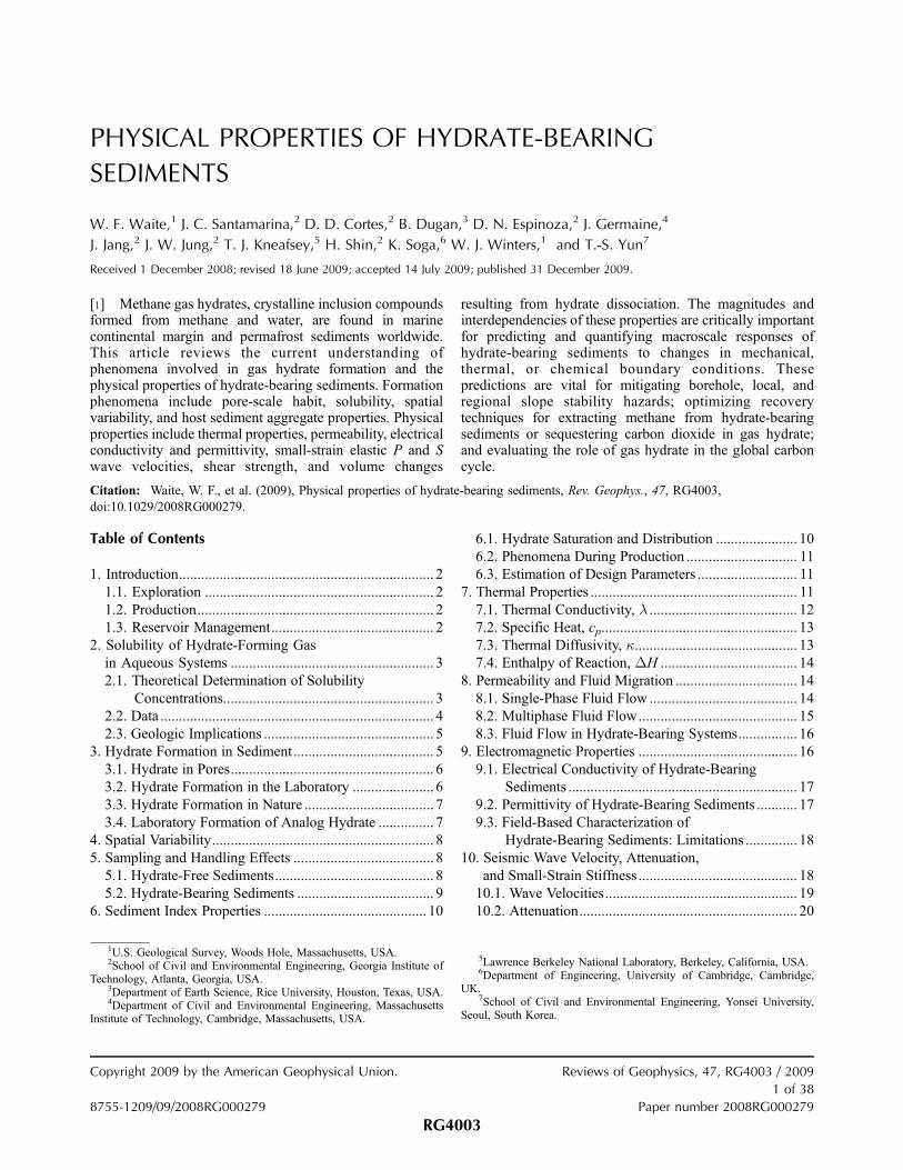
[38] The formation patterns of naturally occurring hydrate
are varied, with an observable distinction between dissem-
inated, pore-filling hydrate in coarse sands compared to
veined or nodule-type hydrate occurrences in fine-grained
sediments (Figure 4). While the formation of hydrate near
faults and at the base of the hydrate stability zone may take
place in the presence of free gas, hydrate formation in
sediments within the gas hydrate stability zone most likely
utilizes dissolved, aqueous phase methane [e.g., Buffett and
Zatsepina, 2000]. This requires a methane source within the
sediment such as biogenic, microbial activity and/or the
transport of either biogenic or thermogenic methane via
diffusion or advection from deeper strata.
[39] Hydrate occurrences in the Nankai Trough offshore
Japan have been characterized as pore filling [Murray et al.,
2006]. In the Blake Ridge, off the southeast coast of the
United States, hydrate has been characterized as cementing
by Guerin et al. [1999] but as load bearing by Helgerud et
al. [1999]. As a rule of thumb, however, acoustic, electrical,
or nuclear magnetic resonance (NMR) estimates of hydrate
saturation suggest hydrate in sands can be characterized
with load-bearing models when the hydrate saturation
exceeds 25%–30% [Kleinberg and Dai, 2005; Lee and
Waite, 2008] except in high gas flux areas [Bohrmann et al.,
1998] or where gas is recycled into the hydrate stability
zone, allowing hydrate to form as a cement [Guerin et al.,
1999; Yuan et al., 1999].
3.4. Laboratory Formation of Analog Hydrate
[40] Tetrahydrofuran (C4H8O, hereinafter referred to as
THF) hydrate has been used in place of methane hydrate in
laboratory studies [Handa et al., 1984; Leaist et al., 1982;
Lee et al., 2007; Rueff and Sloan, 1985; Yun et al., 2005,
2007; Cortes et al., 2009]. Concerns related to the polar
nature of the THF molecule compared to the nonpolar
nature of the methane molecule have been raised, but this
polarity difference between THF and methane loses rele-
vance in the context of hydration processes because the
large size and structure of the THF molecule significantly
weaken polarity-based ionic interactions between water and
THF. Implications of THF’s polar nature regarding hydrate
research are discussed by Lee et al. [2007].
[41] The main advantage of THF relative to methane is its
complete miscibility in water, which enables relatively
rapid, homogeneous synthesis of THF hydrate and control
of the hydrate volume fraction in sediments [Yun et al.,
2007; Lee et al., 2007]. No gas phase is present during
Figure 4. Modes of hydrate occurrence: (a) Hydrate(white) saturating pore space of a coarse-grained samplefrom the 1998 Mallik 2L-38 permafrost hydrate researchwell. (b) Veined hydrate (white) in fine-grained sediment fromthe Krishna Godavari Basin, offshore India. (c) Sediment-coated hydrate chunks from fine-grained sediment in theGulf of Mexico. Photos in Figures 4a and 4c by W. Winters,U.S. Geological Survey. Photo in Figure 4b courtesy of theNational Gas Hydrate Program (NGHP) Expedition 01Scientific Party. Scale bars indicate 5 cm.
RG4003 Waite et al.: PHYSICAL PROPERTIES OF HYDRATE-BEARING SEDIMENTS
7 of 38
RG4003

hydrate formation, meaning hydrate is not forced to form at
or near grain contacts. Instead, it is thought that THF
hydrate nucleates on mineral surfaces and grows into the
pore space. THF hydrate does not dissociate to a gaseous
phase, however, meaning many production-related processes
are difficult to study with this analog, though production
issues based on THF data are discussed by Lee et al. [2009].
Within these limitations, hydrate-bearing sediments prepared
with THF hydrate have allowed the study of a wide range of
material parameters that provide valuable insight to natural
hydrate-bearing sediments [Lee et al., 2007; Santamarina
and Ruppel, 2008; Yun et al., 2005, 2007; Lee et al., 2008;
Cortes et al., 2009].
4. SPATIAL VARIABILITY
[42] Spatial variability affects all Earth processes, includ-
ing all forms of diffusion, flow, and conduction. In turn,
these processes impose spatial variability on the pressures,
temperatures, and availability of water and methane that
define the local gas hydrate stability field [Chen and
Osadetz, 2008; Ginsburg and Soloviev, 1998; Judd and
Hovland, 2007; Wood et al., 2002]. Spatially varying
hydrate distributions affect the interpretation of measure-
ments used to characterize gas hydrate, the procedures for
extracting methane from hydrate as an energy resource, and
the analysis of hydrate-related geohazards.
[43] Spatial variability in hydrate-bearing sediments is
found from the scale of gas hydrate–bearing reservoirs to
the submicron scale (Figure 5). Figure 5a presents a seismic
line from the Indian National Gas Hydrate Program (NGHP)
drill site NGHP-01-21. The vertical scale in Figure 5a is
several hundred meters; thus the smallest observed spatial
variability is on the order of tens ofmeters. The location of the
ocean floor, a domed structure and stratolithologic variability
of the medium below the ocean floor, locations of subocean
floor gas, a significant fault, and a possible debris flow can all
be inferred from the profile. The presence of methane
hydrate, sustained by the confluence of gas accumulation in
the dome-like structure with appropriate pressure and tem-
perature conditions, further alters the system’s permeability,
stiffness, and thermal and electrical properties.
[44] Figure 5b contains well log and core sample data
from hole NGHP-01-10D from the Indian NGHP. Logging
provides a degree of ‘‘ground truth’’ quantification of
physical property differences between stratigraphic layers
inferred from seismic data. The finer resolution of logging
relative to shipboard seismic data reveals vertical hetero-
geneities on the order of meters to centimeters in which
properties such as water content and bulk density can vary
significantly even within a single stratum.
[45] Figure 5c shows spatial variability of elastic wave
velocities on the centimeter scale. Shear and compressional
wave velocities (Vs and Vp) of a pressure core, continuously
maintained at its in situ pore pressure, were measured
approximately every 7 cm using the instrumented pressure
testing chamber. The higher seismic velocities 35 cm from
the top suggest increased sediment stiffness, possibly due to
the presence of gas hydrate.
[46] Figure 5d demonstrates millimeter-scale variability
in density images provided by 3-D X-ray computed tomog-
raphy (CT) of preserved NGHP core. Additional NGHP CT
tomographic images are given by Clayton et al. [2008] and
Holland et al. [2008]. Dark, hydrate-bearing veins are
apparent in this fine-grained sediment, demonstrating how
hydrate can be inhomogeneously distributed even within a
single hydrate-bearing layer. The veins themselves are often
a collection of still finer-scale veins [Priest et al., 2008].
[47] X-ray microtomography can reveal submillimeter-
scale features, such as in the structure of a frozen sandstone
from the Nankai Trough containing hydrate and ice, shown
in Figure 5e with a pixel resolution of 5.5 mm. Though at
this scale the sample appears somewhat homogeneous, the
analysis of possible flow paths through a small portion of
the sample shows considerable variability. As Figure 5f
demonstrates for a laboratory-made specimen, flow vari-
ability can result from the heterogeneous, micron-scale pore
space distribution of gas, hydrate, and water.
[48] Each of these measurement scales provides a differ-
ent perspective on the system. Kilometer-scale measure-
ments are needed to understand large-scale system behavior
such as the geologic plumbing and structural traps needed
for transporting and concentrating methane. Meter-scale
logging and core-based measurements provide system char-
acterizations relevant to methane production applications.
Pore-scale observations underlie the conceptual models
required for understanding electrical, mechanical, and hy-
draulic properties of hydrate-bearing sediments.
5. SAMPLING AND HANDLING EFFECTS
[49] Geologic sampling inevitably disturbs natural sedi-
ments. The presence of hydrate adds further difficulties
during sampling and may aggravate sampling disturbance.
Sampling effects in hydrate-free and hydrate-bearing sedi-
ments are reviewed here.
5.1. Hydrate-Free Sediments
[50] Sampling-induced changes in the mechanical prop-
erties of hydrate-free sediments have been recognized and
extensively studied in the geotechnical community. Rele-
vant observations include (1) pore pressure decreases from
the in situ hydrostatic pressure when samples are extruded
from core recovery systems, potentially subjecting the
sample to an effective stress comparable to the in situ
vertical effective stress [Kimura and Saitoh, 1984]; (2)
reduced undrained strength due to the stress release [Hight
et al., 1992; Ladd and Lambe, 1963; Santagata and
Germaine, 2002; Skempton and Sowa, 1963]; (3) more
pronounced effects on the loss of effective stress and
undrained strength for soils with plasticity index, PI, below
10%–15% [Kimura and Saitoh, 1984;Matsuo and Shogaki,
1988; Siddique et al., 2000]; (4) decrease in small-strain
shear stiffness (Gmax) in stiff and/or cemented soils, yet an
increase in Gmax for very soft sediments (database and
RG4003 Waite et al.: PHYSICAL PROPERTIES OF HYDRATE-BEARING SEDIMENTS
8 of 38
RG4003

interpretation by Rinaldi and Santamarina [2008]); (5)
increased axial strain at peak deviatoric stress with in-
creased disturbance [Siddique et al., 2000]; and (6) friction
between the sampler and sediments during sampling, which
may produce shear failure and plastic deformation [Arman
and McManis, 1977; Hvorslev, 1949; Young et al., 1983].
5.2. Hydrate-Bearing Sediments
[51] Additional sample disturbance should be expected if
pore fluid depressurization leads to gas coming out of
solution [Young et al., 1983] and hydrate dissociation.
These changes are often not uniform and can impart
additional spatial variability to the sample.
Figure 5. Spatial variability over a range of scales. (a) Seismic line crossing drill site NGHP-01-21(modified from Collett et al. [2008]). Deep-seated high-amplitude reflectors indicate the occurrence offree gas as well as a potential shallow debris flow (vertical scale � 750 m). (b) Well log (curves) and coredata (points) for site NGHP-01-10 showing profiles of water content and bulk density (modified fromCollett et al. [2008]). (c) Compressional and shear wave velocity measured by the instrumented pressuretesting chamber (NGHP specimen 21A-03E) (Yun et al., submitted manuscript, 2009) (modified fromCollett et al. [2008]). (d) X-ray computed tomography (CT) scan of a core segment from NGHP 21H(T. Kneafsey, unpublished data, 2007). (e) Three-dimensional X-ray CT image of a sand sample retrievedfrom the Nankai Trough. The white box is 1.2 mm on a side (reproduced from Jin et al. [2007]). Flow isinhomogeneous through this seemingly uniform sample because of pore-scale variability, as observed inFigure 5f. (f) X-ray MicroCT imagery showing the distribution of mineral grains (dark gray), gas (black),water (light gray), and hydrate (white) in a laboratory-made sample (reproduced from Jin et al. [2006]).
RG4003 Waite et al.: PHYSICAL PROPERTIES OF HYDRATE-BEARING SEDIMENTS
9 of 38
RG4003
[52] Sampling disturbance in hydrate-bearing sediments
can be reduced with pressure coring, in which pore fluid
pressure and temperature conditions are maintained within
the stability field. Pressure coring was first successfully
applied to hydrate-bearing sediment during Ocean Drilling
Program Leg 164 [Dickens et al., 1997]. Two pressure
coring systems currently in use, the HYACE Rotary Corer
and the Fugro Pressure Corer, use a motor driven by mud
circulation to rotate the cutting shoe and a water hammer
driven percussion to drive the core barrel up to 1 m ahead of
the drill bit. The sample is retrieved inside a pressure vessel
after closing a valve to preserve the in situ pore fluid
pressure.
[53] Pressure coring reduces, but does not eliminate,
sample disturbance when recovering hydrate-bearing sedi-
ment [Yun et al., 2006]. Current measurement techniques
are ineffective at discerning whether observed features
reflect in situ conditions or handling and measurement
artifacts due to the following:
[54] 1. The loss of effective stress, which eventually
decreases nearly to zero in the sediment, results in the
sampling effects listed in section 5.1 for sediments without
hydrates. The state of effective stress can be restored after
sampling, but the in situ soil fabric and internal structure are
not fully recoverable.
[55] 2. Shear along the soil–core liner interface affects
the periphery of cores even when conditions are kept within
the hydrate stability field for their entire recovery and
measurement history, as observed in electrical conductivity
profiles obtained with millimeter-scale resolution from the
periphery of pressure cores (T. S. Yun et al., Hydrate
bearing sediments from Krishna-Godavari Basin: Physical
characterization, pressure core testing and scaled production
monitoring, submitted to Marine and Petroleum Geology,
2009).
[56] 3. Creep and diffusion processes are anticipated to
affect hydrate distribution and the physical properties mea-
sured after pressure cores have been stored for prolonged
periods of time.
6. SEDIMENT INDEX PROPERTIES
[57] The properties and behavior of sediments result from
complex mechanical, hydraulic, electrical, thermal, and
chemical interactions between mineral grains and pore
fluids. These interactions are expressed in terms of sediment
index properties, which capture grain and pore fluid char-
acteristics that have profound effects on the morphology,
extent, and growth characteristics of natural gas hydrate
[Winters et al., 1999]. Index properties can be used to
anticipate hydrate occurrence, foresee phenomena during
production, and estimate engineering properties for design.
Salient index properties are listed in Table 3. Note that
Tables 3–5 draw a distinction between coarse sediments,
with a fines content below 7%, and fine-grained sediment
having a fines content exceeding 15% of the sediment by
mass. This distinction is drawn because the fines content,
meaning the fraction of sediment grains smaller than 0.075
mm, exerts considerable control over the sediment behavior.
6.1. Hydrate Saturation and Distribution
[58] Gas hydrates are found in coarse-grained, fine-
grained, and fracture-dominated reservoirs [Collett et al.,
2008; Trehu et al., 2006]. As shown in Table 4, field studies
suggest that correlations can be made between grain size,
other sediment characteristics, and the modes of hydrate
occurrence [Booth et al., 1996, 1998]. Coarse-grained
reservoirs, such as those found in the Mallik permafrost
site in Canada and the Nankai Trough offshore Japan, tend
to develop gas hydrate as a pore-filling material, occasion-
ally reaching pore saturations of 80% (Table 4) [Dallimore
et al., 1999; Winters et al., 1999]. Low volume fractions of
hydrate are reported in fine-grained layers at these sites.
[59] Hydrate has been found extensively in fine-grained
sediments elsewhere, however. For some cores taken at sites
including the Blake Ridge offshore the U.S. east coast, Gulf
of Mexico, offshore Taiwan, Hydrate Ridge offshore west-
ern Canada, and Indian Ocean, hydrates were found in fine-
grained clayey sediments where the mass of fines content is
typically over 60% and as high as 90%. Because of their
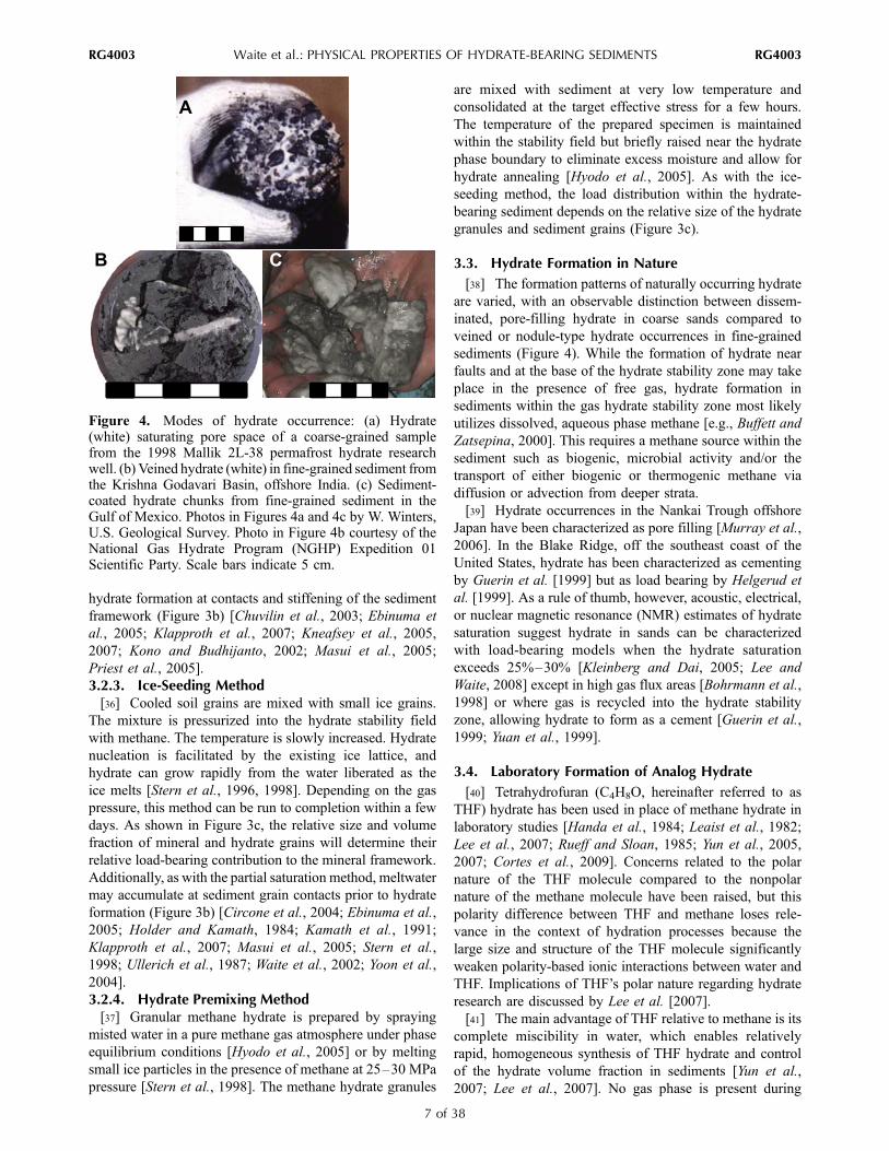
TABLE 3. Index Property Definitionsa
Sediment Type Property Definition
General soil classificationporosity, fb f = Vv/VT
specific gravity of solids, Gs Gs = rs/rwbulk density, rb (kg m�3) rb = MT/VT
water content, w w = Mw/Ms
pore space hydratesaturation, Sh
bSh = Vh/Vv
mineralogyorganic contentcarbonate contentpreconsolidation stress (kPa)
Coarse grained particle size distribution D10, D60, D30
particle size distribution Cunif = D60/D10
particle size distribution Ccurv = (D30)2/(D10D60)
particle shapepore size distributionextreme void ratio, emin, emax e = Vv/Vs
Fine grained Atterberg limit: liquid limit LLAtterberg limit: plastic limit PLAtterberg limit: plasticity index PI = LL � PLAtterberg limit: liquidity index LI = (w � PL)/PIactivity, mineralogyspecific surface, Ss (m
2 g�1)Pore fluid salinity
pHaNotation is as follows: Ccurv, coefficient of curvature; Cunif, coefficient
of uniformity; D10, diameter at which 10% of sample is finer; D30, diameterat which 30% of sample is finer; D60, diameter at which 60% of sample isfiner; e, void ratio; emax, maximum void ratio (minimum grain packing);emin, minimum void ratio (maximum grain packing); LI, liquidity index;LL, liquid limit; PI, plasticity index; PL, plastic limit; Ms, mass of solids;MT, total mass; Mw, mass of water; Vh, volume of hydrate; Vs, volume ofsolids; VT, total volume; Vv, volume of voids; w, gravimetric water contentbased on mass of minerals; rs, density of solids; rw, density of water. Theseproperties and the means by which they are measured are discussed furtherby Lambe and Whitman [1969] and Mitchell and Soga [2005].
bThough porosity, f, and pore space hydrate saturation, Sh, are oftenreported as percentages, formulae in which they appear typically require theunitless values defined here in Table 3.
RG4003 Waite et al.: PHYSICAL PROPERTIES OF HYDRATE-BEARING SEDIMENTS
10 of 38
RG4003

abundance, fine-grained marine sediments collectively con-
tain more gas hydrate than all coarse-grained reservoirs,
even though disseminated gas hydrate saturations in the
pore space of fine-grained sediments are typically <10%. As
indicated in Figures 4 and 5, however, hydrate in fine-
grained sediments often forms in localized areas of elevated
permeability associated with slightly increased sediment
grain size [Ginsburg et al., 2000] or faults [Nimblett and
Ruppel, 2003; Wood and Ruppel, 2000]. In these cases,
hydrate can form inhomogeneously as discrete nodules,
sheets, or lenses [Clennell et al., 1999; Cook et al., 2008;
Stern and Kirby, 2008; Trehu et al., 2004].
6.2. Phenomena During Production
[60] Index properties can be used to predict sediment
behavior during methane production. For example, sand
production [Walsh et al., 2009] or flow clogging due to
migrating fine-grained material [Goldsztein and Santamar-
ina, 2004; Valdes and Santamarina, 2007] may accompany
methane production from coarse-grained hydrate-bearing
sediments, while hydraulic fracturing and leaky reservoirs
should be expected when producing methane from fine-
grained sediments.
6.3. Estimation of Design Parameters
[61] The use of index properties to obtain qualitative or
semiquantitative estimates of baseline (hydrate-free) sedi-
ment behavior is based on correlations developed for sedi-
ments around the world [Lambe and Whitman, 1969;Mayne
et al., 1992; Mitchell and Soga, 2005; Santamarina et al.,
2001; Terzaghi et al., 1996]. Examples are presented in
Table 5.
7. THERMAL PROPERTIES
[62] A material’s response to the addition or loss of heat
is described using the thermal conductivity, l (W m�1
K�1); specific heat, cp (J kg�1 K�1); and thermal diffusivity,
k (m2 s�1). Heat flow in materials undergoing a phase
change such as hydrates undergoing formation or dissocia-
tion is described by the enthalpy of reaction, DH (J mol�1).
The thermal properties of hydrate-bearing sediment compo-
nents are summarized in Tables 6 and 7.
TABLE 4. Dominant Characteristics of Gas Hydrate–Bearing Reservoirs
Reservoir TypeSedimentType
Dominant GasHydrate Type Maximum Sh (%) LL (PI) Locations References
Coarse grained sand, gravel pore filling 80 – Mackenzie Delta Dallimore et al. [1999],Uchida and Takashi [2004],and Winters et al. [1999]
– Nankai Trough Uchida and Takashi [2004]Fine grained clay, silt finely disseminated,
nodules, layerstypically 10 exceptin discrete layers ofsegregated hydrate
0.68–0.99(0.44–0.64)
Blake Ridge Paull and Matsumoto [2000],Trehu et al. [2004],Winters [2000], andWinters et al. [2007]
0.51–1.02(0.28–0.57)
Gulf of Mexico Francisca et al. [2005] andYun et al. [2006]
0.64–0.87(0.25–0.45)
Hydrate Ridge Tan et al. [2006]
0.73–0.75(0.34–0.36)
offshore India Yun et al. (submittedmanuscript, 2009)
Fractured clay, silt complex vertical veins 100 in discretefractures
unknown offshore India Collett et al. [2008] andWinters et al. [2008]
TABLE 5. Correlations Between Baseline Hydrate-Free Sediment Index Propertiesa
Parameter Correlation Reference
Compressibility Cc � 0.009(LL � 10) Terzaghi et al. [1996]Cc � [(PI)Gs]/200 Wroth and Wood [1978]
Shear strength Su = sv0[0.11 + 0.0037(PI)] Skempton [1957]
Friction angle (fine) Fcv = 0.8 � 0.094 ln (PI) Mitchell and Soga [2005]Friction angle (coarse) Fcv = 42 � 17R Santamarina and Cho [2004]Hydraulic conductivity (fine) K = 1
S2s
q gwmr2m
e3
1þe Perloff and Baron [1976]
Hydraulic conductivity (coarse) K = CH(D10)2 Hazen’s equation [Holtz and Kovacs, 1981]
emax emax = 0.359 + 0.082R�1 Santamarina and Cho [2004]emin emin = 0.554 + 0.154R�1 Santamarina and Cho [2004]
aNotation is as follows: Cc, compression index; CH, Hazen’s empirical coefficient, �100 (cm s)�1 or 1 � 104 (m s)�1 [Carrier, 2003]. D10, diameter atwhich 10% of sample is finer; e, void ratio; emax, maximum void ratio; emin, minimum void ratio; K, hydraulic conductivity; LL, liquid limit; PI, plasticityindex; R, roundness (particle shape); Ss, specific surface; Su, undrained shear strength; gw, unit weight of water = rwg, where rw is mass density of water andg is 9.8 m s�2; m, dynamic fluid viscosity; q, shape and tortuosity factor; rm, mass density of mineral grains; sv
0, effective overburden stress at failure; Fcv,friction angle during constant volume shear, also known as the critical state friction angle.
RG4003 Waite et al.: PHYSICAL PROPERTIES OF HYDRATE-BEARING SEDIMENTS
11 of 38
RG4003

7.1. Thermal Conductivity, l[63] Thermal conductivity quantifies the efficiency of
heat transport. In sediments, this involves transport (1) from
grain to grain, (2) from grain to liquid to grain, and (3)
through pore-filling liquid [deMartin, 2001; Waite et al.,
2002; Yun and Santamarina, 2008]. Rather than calculate
the contribution of each heat transport path explicitly,
thermal conductivity is often estimated using a two-phase
mixing model to combine the thermal conductivities of the
sediment grains with the pore fluid. As shown in Tables 6
and 7, the thermal conductivities of methane hydrate and
water differ by <10% at the temperatures found in hydrate-
bearing sediments [Huang and Fan, 2004; Waite et al.,
2007; Weast, 1987]. For this reason, first-order thermal
conductivity estimates can neglect the presence of methane
hydrate and assume the sediment pore space contains only
water [Ruppel, 2000].
[64] The presence of gas complicates the analysis by
adding a phase with strongly contrasting thermal properties
(Table 6). The pore fluid can no longer be treated simply by
averaging the thermal conductivities of water and gas
because as the wetting phase, water migrates to contacts
and enhances grain-to-grain conduction. Hence, even low
degrees of water saturation have a strong effect on thermal
conductivity [Andersland and Ladanyi, 2004; Farouki,
1985; Lu et al., 2007; Singh and Devid, 2000].
[65] As described by Cortes et al. [2009], even in gas-
free systems, precise thermal conductivity calculations must
account for sediment-altering processes caused by hydrate
formation, including porosity changes [Tarnawski et al.,
2002] and the associated effective stress changes [Sridhar
and Yovanovich, 1996], as well as the improved thermal
transport across the sediment grain–hydrate interface com-
pared to the sediment grain–water interface [Swartz and
Pohl, 1989].
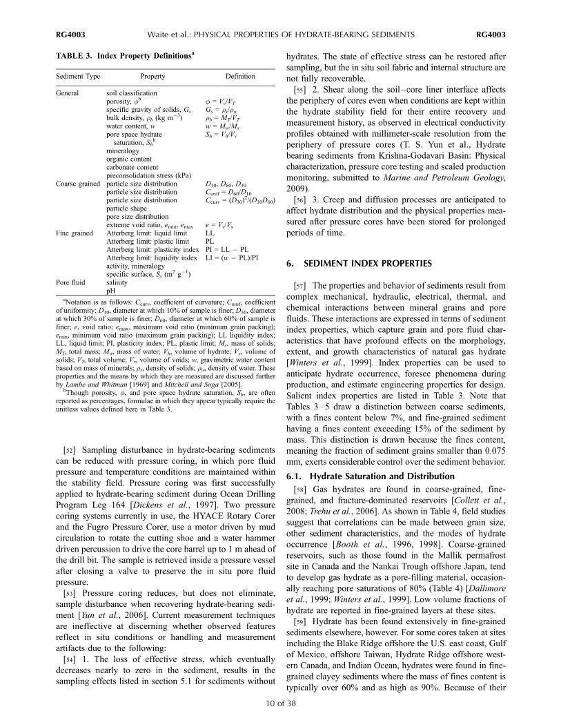
[66] Despite these shortcomings, simple mixing models
provide reasonable bounds for thermal conductivity values.
As shown in Table 8 and Figure 6, the parallel model, in
which heat travels simultaneously through the pore fill and
the sediment grains, and the series model, in which heat
TABLE 6. Thermal Properties of Hydrate-Bearing Sediment Componentsa
Material l (W m�1 K�1) k (m2 s�1) cp (J kg�1 K�1) r (kg m�3)
Air 0.024b (273 K) 183 � 10�7c 1010b (273 K) 1.298d (272 K)Water 0.56e (273 K) 1.33 � 10�7c 4218e (273 K) 999.9e (273 K)Water 0.58e (283 K) 1.38 � 10�7c 4192e (283 K) 999.7e (283 K)Ice Ih 2.21f (270 K) 11.7 � 10�7c 2052g (270 K) 917h (273 K)Methane gas 0.0297i (260 K, 1 MPa) 18.0 � 10�7c 2170d (260 K) 7.61j (260 K, 1 MPa)Methane gas 0.099i (260 K, 40 MPa) 1.6 � 10�7c 2170d (260 K) 286j (260 K, 40 MPa)Methane hydrate, CH4 � 6H2O 0.57k (263 K) 3.35 � 10�7l 2031m (263 K) 929n (263 K)THF + water, THF � 17H2O 0.47f,o (283 K) 3.12 � 10�7c 4080p (282 K) 982q (283 K)THF hydrate, THF � 17H2O 0.5f (261 K) 2.55 � 10�7f 2020f (261 K) 971r (273 K)THF hydrate, THF � 17H2O 0.5f (261 K) 2.60 � 10– 7c 1980s (260 K) 971r (273 K)Quartz 7.7 to 8.4t 41 � 10�7c 730b (273 K) 2650h
aTemperature is in kelvins, and pressure is in megapascals. THF, tetrahydrofuran.bKaye and Laby (Tables of Physical and Chemical Constants, National Physical Laboratory, 2008, http://www.kayelaby.npl.co.uk/).cCalculated from equation (4).dEngineering ToolBox (Material Properties, available at http://www.engineeringtoolbox.com/).eWeast [1987]. mHanda [1986].fWaite et al. [2005]. nWaite et al. [2007].gLeaist et al. [1982]. oBASF Corporation [1998].hDvorkin et al. [2000]. pTombari et al. [2006].iVargaftik et al. [1993]. qSmallwood [2002].jSychev et al. [1987]. rMork et al. [2000].kHuang and Fan [2004]. sHanda et al. [1984].lTurner et al. [2005]. tRevil [2000].
TABLE 7. Temperature Dependence of Methane Hydrate Thermal Propertiesa
Temperature Dependence Fit Equations Temperature Range
l (W m�1 K�1) = �(2.78 ± 0.05) � 10�4T (�C) + (0.624 ± 0.001) �20�C to 17�Cb
l (W m�1 K�1) = �1.99 � 10�4T (�C) + 0.682 �12�C to 4�Cc
kd (m2 s�1) = (4.70 ± 0.02) � 10�5/T (K) + (1.35 ± 0.03) � 10�7 �128�C to 17�Cb (145 to 290 K)cp (J kg
�1 K�1) = (6.1 ± 0.3)T (�C) + (2160 ± 20) 1�C to 17�Cb
cp (J kg�1 K�1) = 13T (�C) + 2215 �9�C to 3�Ce
aTemperatures in Celsius unless otherwise noted.bWaite et al. [2007], measured at 31.5 MPa.cRosenbaum et al. [2007], measured between 2.5 and 43.7 MPa.dThe T�1 dependence of the k fit requires input temperatures in kelvins.eNakagawa et al. [2008], measured at 5 MPa.
RG4003 Waite et al.: PHYSICAL PROPERTIES OF HYDRATE-BEARING SEDIMENTS
12 of 38
RG4003
alternates between flowing through the pore fill and the
sediment, provide the upper and lower bounds, respectively,
for thermal conductivity. The models of Krupiczka [1967],
Maxwell [1954], and Revil [2000], collected by Revil
[2000], yield similar results lying midway between the
upper and lower bounds.
7.2. Specific Heat, cp
[67] Specific heat measures the heat stored in, or
extracted from, a material due to a temperature change.
Unlike thermal conductivity, specific heat depends only on
the mass fractions of sediment, hydrate, and water rather
than on their pore-scale distribution and interfacial effects.
Using the subscripts m, w, and h to refer to the host
sediment mineral, pore water, and methane hydrate, respec-
tively, the formation’s bulk specific heat, cp.b, is given for a
gas-free system by
cp:brb ¼ cp:mrm 1� fð Þ þ cp:wrw 1� Shð Þfþ cp:hrhShf; ð2Þ
where rb is given by the mass fractions of the sediment
grains, water, and hydrate,
rb ¼ rm 1� fð Þ þ rw 1� Shð Þfþ rhShf: ð3Þ
Here the porosity, f, and hydrate saturation, Sh, must be
considered in decimal notation rather than in units of
percent.
[68] Because the specific heat of methane hydrate is less
than half that of water, hydrate formation can significantly
lower the specific heat of hydrate-bearing sediments [Waite
et al., 2007]. Hydrate-bearing layers with potentially eco-
nomic hydrate saturations for production, such as the Mallik
5L-38 permafrost hydrate well with porosity, f, of �35%and methane hydrate saturation, Sh, of �80% [Collett et al.,
2005], are particularly affected by the presence of hydrate
[Kurihara et al., 2005; Moridis et al., 2005]. Depending on
sediment porosity, even in sediments with moderate hydrate
saturations of 20%–40%, the specific heat is reduced by
�10% relative to hydrate-free sediment [Waite et al., 2007].
7.3. Thermal Diffusivity, k[69] Thermal diffusivity is a measure of the rate at which
a body changes temperature when subjected to an external
heat flux. In the absence of systematic studies of thermal
diffusivity, we quantify the effect of hydrate on the proper-
ties of hydrate-bearing sediment by combining the thermal
conductivity, l; specific heat, cp; and density, r, results
discussed in sections 7.1 and 7.2 with the definition of
thermal diffusivity, k,
k ¼ lrcp
: ð4Þ
[70] The thermal diffusivity of methane hydrate is more
than twice that of water; therefore, hydrate-bearing sedi-
Figure 6. Model predictions for mixtures of quartz(8.0 W m�1 K�1) and water (0.6 W m�1 K�1). White regiondenotes the range of relevant porosities.
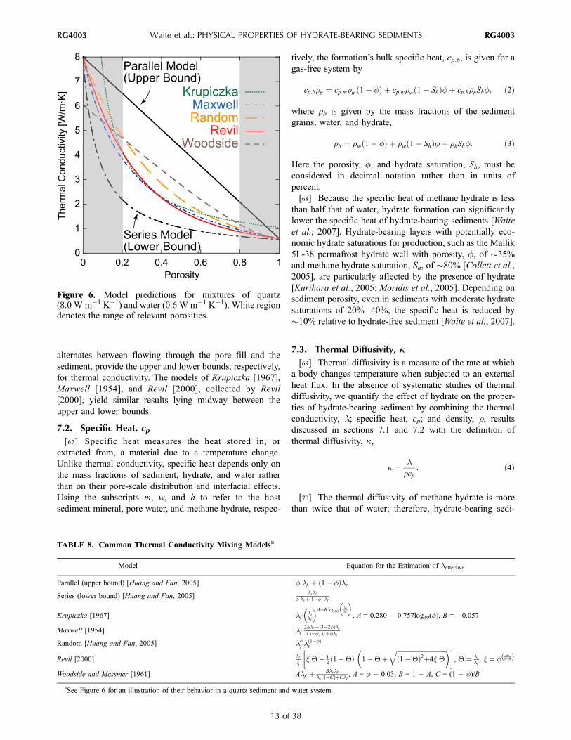
TABLE 8. Common Thermal Conductivity Mixing Modelsa
Model Equation for the Estimation of leffective
Parallel (upper bound) [Huang and Fan, 2005] f lf þ 1� fð Þls
Series (lower bound) [Huang and Fan, 2005]lslf
f lsþ 1�fð Þ lf
Krupiczka [1967] lflslf
� �AþB log10lslf
� �, A = 0.280 � 0.757log10(f), B = �0.057
Maxwell [1954] lf2flf þ 3�2fð Þls3�fð Þlf þfls
Random [Huang and Fan, 2005] lff l
1�fð Þs
Revil [2000]lfx x Qþ 1
21�Qð Þ 1�Qþ
ffiffiffiffiffiffiffiffiffiffiffiffiffiffiffiffiffiffiffiffiffiffiffiffiffiffiffiffiffiffiffiffi1�Qð Þ2þ4x Q
q� �� �, Q ¼ ls
lf, x ¼ f
m1�mð Þ
Woodside and Messmer [1961] Alf þ Blslfls 1�Cð ÞþClf
, A = f � 0.03, B = 1 � A, C = (1 � f)/B
aSee Figure 6 for an illustration of their behavior in a quartz sediment and water system.
RG4003 Waite et al.: PHYSICAL PROPERTIES OF HYDRATE-BEARING SEDIMENTS
13 of 38
RG4003

ments can change temperature more rapidly than hydrate-
free sediments [Waite et al., 2007]. In sediment with
porosity f = 35%, a hydrate saturation Sh = 35% increases
heating rates by more than 10% relative to those in the
absence of hydrate. This effect is magnified in high-porosity
formations, such as the 74% porosity, near-surface sedi-
ments on the Congo continental slope [Sultan et al., 2004b].
In this environment, hydrate saturations of only 19%–22%
reduce heating times relative to hydrate-free sediment by
more than 10%. Hydrate should therefore be accounted for
in transient heat flow applications such as safety assess-
ments for drilling into or through hydrate-bearing sediment
[Briaud and Chaouch, 1997; Hadley et al., 2008; Ji et al.,
2003; Pooladi-Darvish, 2004].
7.4. Enthalpy of Reaction, DH
[71] The organized hydrate structure has less internal
energy than a freely moving, disordered combination of
methane and water, so energy must be released for hydrate
to form and reabsorbed for hydrate to dissociate [Rydzy et
al., 2007]. This energy change is defined as the enthalpy of
reaction, DH.
[72] Calorimetry can provide measurements of DH, but
only a limited number of studies are available. Enthalpies
can also be estimated from phase equilibrium and thermo-
dynamic data using the Clausius-Clapeyron equation to
relate pressure, P; temperature, T; enthalpy, DH; and
compressibility, Z:
d lnP
d1
T
� � ¼ �DH
ZR; ð5Þ
where R is the ideal gas constant. The validity of this
method is contingent upon negligible changes in compres-
sibility. There is good agreement between experimental
results and indirectly derived enthalpies from the Clausius-
Clapeyron method.
[73] The ice-water enthalpy of melting is �6 kJ mol�1
[Handa, 1986; Kumano et al., 2007]. Per mole of guest
molecule, the enthalpy of dissociation of structure I methane
hydrate into methane gas and liquid water is DH = 52.7–
56.9 kJ mol�1 at T � 0�C [De Roo et al., 1983; Deaton and
Frost, 1946; Handa, 1986; Kang et al., 2001; Kuuskraa et
al., 1983; Lee et al., 2005; Lievois et al., 1990; Rueff et al.,
1988; Sloan and Fleyfel, 1992; Voronov et al., 2008]. DH
is insensitive to pressure and temperature for conditions
typical in terrestrial applications, remaining in the range
54.44 ± 1.46 kJ mol�1 between 5.5 and 19.3 MPa and
7.5�C–18.5�C [Gupta et al., 2008].
[74] Replacing just 1% of the hydrate methane with
ethane, however, increases DH by �30% to 68.7 kJ mol�1
[Rydzy et al., 2007], and a structure II propane hydrate has
a DH of 129.2 kJ mol�1 [Handa, 1986]. This illustrates that
DH depends on the guest molecule but is primarily con-
trolled by the number of hydrogen-bonded water molecules.
Typically, there are �6 water molecules per guest molecule
in structure I hydrate [Circone et al., 2005, 2006] but �17per guest in structure II hydrate [Davidson, 1973].
[75] The heat of reaction can be significant when gener-
ating hydrate for storing large volumes of gases. When
dissociating hydrate to produce methane from permafrost
regions or beneath the ocean floor, the heat absorbed during
hydrate dissociation can cool the surroundings, resulting in
secondary hydrate or ice formation, both of which reduce
the permeability of the producing formation [Moridis et al.,
2008]. Moreover, the enthalpy variation with guest occu-
pant means the heat of reaction for dissociation may not be
constant throughout a formation, nor over the lifetime of a
production well, complicating production rate predictions.
8. PERMEABILITY AND FLUID MIGRATION
[76] Permeability controls fluid migration through sedi-
mentary systems and plays an important role in heat and
chemical transfer occurring via fluid migration. In hydrate-
bearing sediments, permeability affects dissolved gas and
free gas transport as well as the accumulation, distribution,
and concentration of hydrate [Bhatnagar et al., 2007; Garg
et al., 2008; Liu and Flemings, 2007; Nimblett and Ruppel,
2003]; the ability to produce gas from hydrate reservoirs
[Moridis, 2003; Moridis et al., 2004, 2007]; local perturba-
tions of the hydrate stability field [Wood et al., 2002]; and
methane flux to the ocean [Moridis and Reagan, 2007a,
2007b; Reagan and Moridis, 2007]. In spite of the impor-
tance of flow through hydrate-bearing systems [Gbaruko et
al., 2007; Haacke et al., 2007; Hensen and Wallmann,
2005; Shankar et al., 2006], few reliable permeability
measurements are available [Minagawa et al., 2005, 2008;
Nadem et al., 1988].
[77] Macroscale analyses of single-phase and multiphase
flow in sediments generally assume the sediments can be
represented by an equivalent homogeneous porous medium;
however, a proper understanding of conduction properties
requires the pore-scale assessment of the multiple coexisting
phases and of all relevant flow pathways.
8.1. Single-Phase Fluid Flow
[78] Single-phase flow rate, q (m3 s�1), through a porous
medium under laminar conditions is described by Darcy’s
law,
q ¼�krf gmf
dP
rf gþ z
!
dlA; ð6Þ
where A (m2) is the cross-sectional area, z (m) is the
elevation above a reference datum, P (Pa) is the pressure at
elevation z, mf (Pa s) is the dynamic fluid viscosity, l (m) is
the length over which the flow-driving change (P/rg + z) is
measured, k (m2) is the intrinsic permeability of the porous
medium, rf (kg m�3) is the mass density of the fluid, and
g = 9.8 m s�2 is the acceleration due to gravity.
[79] The intrinsic permeability is a measure of fluid
flowability through a porous medium, and it is determined
RG4003 Waite et al.: PHYSICAL PROPERTIES OF HYDRATE-BEARING SEDIMENTS
14 of 38
RG4003

by the interconnectivity and size of voids within the
medium. The tortuosity, q, defined as the ratio (l/lE)2
accounts for the effective flow path, lE, being longer than
the sample length, l. Typical values for q range from 0.4 to
0.8 [Bear, 1972]. Physically, the dependence on void size,
which can also be expressed as a specific surface area, Ss(m2), represents the frictional drag between the flowing
fluid and the sediment grain surfaces.
[80] The Kozeny-Carman model captures the permeabil-
ity’s strong dependence on sediment specific surface area,
Ss; the role of tortuosity, q; and the lesser effect of void
ratio, e (form adapted from Perloff and Baron [1976]):
k ¼ qr2mS2s
� �e3
1þ e
� �; ð7Þ
where the grain mineral density, rm, relates the gravimetric
specific surface to the volumetric nature of permeability
(see other models in Table 5). The intrinsic permeability of a
sediment given in equation (7) can be converted to the
hydraulic conductivity for a given fluid (Table 5) by taking
into consideration the fluid dynamic viscosity, mf, and unit
weight, rfg, through a multiplicative factor, rfg/mf.
[81] The correlation beteween specific surface area and
permeability is readily established with clays (Table 5
[Carrier, 2003]), but it can be useful to relate permeability
to sediment size rather than specific surface area. To convert
from specific surface area to grain size, consider that a
particle’s surface area is determined by its smallest dimen-
sion, which corresponds to the diameter of rotund sandy
grains or the thickness of platy clay particles. When this
observation is extended to the entire sediment mass, it
follows that the specific surface of sediments is governed
by the specific surface of the finest fraction. Hence, k
correlates well with the size of the finer grains in sandy
sediments, D10, as in Hazen’s equation (Table 5).
[82] Given the wide range in particle sizes, permeability
varies over 10 orders of magnitude between clay and clean
sand sediments [Dullien, 1992]. In general, expressions
based on sediment index properties such as Ss and D10
provide order-of-magnitude permeability estimates only. In
addition, other local geologic features such as grain orien-
tation anisotropy, lithology, fractures, stratigraphic variabil-
ity, or hydrate presence can all produce dramatic changes in
the permeability field, and empirical relations should be
used with care.
[83] Laboratory measurements show that permeability is
scale-dependent [Tidwell and Wilson, 1997] as all natural
media have some degree of spatial variability (Figures 4 and
5). Thus, permeability measured on the core scale will differ
from permeability inferred from field-scale flow measure-
ments. Complementary core-scale information gathered
using X-ray CT imaging [Jin et al., 2007], electrical
measurements (section 9), and NMR [Kleinberg et al.,
2005; Kleinberg et al., 2003] helps develop robust concep-
tual models that can then be upscaled based on seismic
imagery to handle field-scale spatial variability in simula-
tions of flow in hydrate-bearing sediments.
8.2. Multiphase Fluid Flow
[84] Steady state immiscible flow in multiphase systems,
such as gas and water flow in hydrate systems, can be
modeled as Darcian flow by incorporating relative perme-
abilities for water, krw, and gas, krg,
qw ¼ �krwkrwgmw
dPw
rwgþ z
� �dl
A ð8Þ
qg ¼ �krgkrgg
mg
dPg
rggþ z
!
dlA: ð9Þ
[85] The dimensionless relative permeabilities krw and krgvary from 0 to 1 and are functions of phase saturations, the
Figure 7. Illustrations showing end-member multiphase fluid saturations and complexity of multiphaseflow. (a and b) Stable fluid interfaces and (c) unstable conditions. In Figure 7a, phases occupy differentchannels according to wettability properties: nonwetting phase (NW) occupies larger pores, and wettingphase (W) occupies smaller pores. In Figure 7b, wetting phase is discontinuous and isolated to small porethroats. The wetting phase irreducible saturation has been reached in Figure 7b, and only the nonwettingfluid flows. In Figure 7c, both phases flow together, one dispersed in the other.
RG4003 Waite et al.: PHYSICAL PROPERTIES OF HYDRATE-BEARING SEDIMENTS
15 of 38
RG4003

spatial distribution of the phases, mineral wettability, and
pore space geometry (Figure 7). Relative permeabilities krwand krg vary with water and gas saturations as shown in
Figure 8 (see Dong and Dullien [2006] for numerical
examples). Note that relative permeabilities typically add
up to <1 because of fluid-to-fluid interactions. For example,
water wets mineral surfaces in most sediments; this prefer-
ential wetting means that gas or oil will tend to occupy
larger pore spaces and significantly reduce water flow.
[86] Water saturation, Sw, is determined by the pressure
difference between fluid and gas, or capillary pressure,
DP = Pg � Pw, which depends on the pore size distribution
in the sediment (see section 2.2). A common model used to
capture this dependency follows the formulations of van
Genuchten [1980], shown here in the form from Parker et
al. [1987],
Sw eff ¼ 1þ an DP
grw
� �n� ��m¼ Sw � Sw irr
1� Sw irr
; ð10Þ
where m = (n � 1)/n. Note that the expression is in terms of
the effective water saturation, Sw_eff, which is the actual
water saturation, Sw, corrected for the sediment irreducible
water saturation, Sw_irr. The fitting parameter a is related to
the modal pore size, while n is a function of the spread of
the pore size distribution. For example, a is 4.57 m�1 and n
is 7.43 for a volcanic sand, a is 1.94 m�1 and n is 9.06 for
Berea Sandstone, and a is 0.15 m�1 and n is 1.17 for Biet
Netofa clay (values for additional materials are compiled by
Carsel and Parrish [1988] and by Ghezzehei et al. [2007]).
[87] In terms of the effective water saturation, the relative
permeabilities of water and gas are given by [Parker et al.,
1987]
krw ¼ S1=2w eff 1� 1� S
1=mw eff
� �mh i2ð11Þ
krg ¼ C 1� Sw effð Þ1=2 1� S1=mw eff
� �2m; ð12Þ
where C is a ‘‘gas slippage’’ correction that approaches 1 as
the grain size increases. Other models include the Brooks
and Corey model [Honarpour et al., 1986; Pruess and
Moridis, 1999] and the Stone power model [Rutqvist and
Moridis, 2007].
8.3. Fluid Flow in Hydrate-Bearing Systems
[88] The presence of hydrate adds additional complica-
tions because hydrate can alter flow and affect permeability
by reducing the pore size and changing the pore shape.
Pore-filling hydrate reduces the permeability more signifi-
cantly than mineral-coating hydrate [Liu and Flemings,
2007]; however, hydrate at grain contacts can readily block
pore throats, causing a more pronounced reduction in
permeability. Based on the limited data available for gas-
free, hydrate-bearing systems [Minagawa et al., 2008],
pore-filling hydrate models provide the best estimates of
permeability [Kleinberg et al., 2003; Lee, 2008].
[89] Water-saturated systems evolve into multiphase gas
and water systems if gas invades the hydrate stability field
[Flemings et al., 2003; Liu and Flemings, 2006, 2007] or if
hydrate begins dissociating [Tryon et al., 2002]. The van
Genuchten model described in section 8.2 has been adapted
to the simulation of dissociation in hydrate-bearing sedi-
ments [Hong and Pooladi-Darvish, 2005; Moridis et al.,
2005]. However, the evolution of water saturation and
capillary pressure during dissociation differs from imbibi-
tion processes typically used to determine the water reten-
tion curve and relative permeability values for sediment.
[90] There are also additional particle-scale mechanisms
that impact relative permeability. For example, where hy-
drate supports the frame of the medium, permeability may
increase as hydrate is removed from the system but then
decrease as the granular skeleton collapses. Hence, further
research is still required to better quantify relative gas and
water permeabilities in hydrate-bearing sediment and their
evolution during dissociation.
9. ELECTROMAGNETIC PROPERTIES
[91] Three electromagnetic phenomena have direct appli-
cations to the study of hydrate-bearing sediments: steady
state charge migration under an applied constant electric
field (conduction), frequency-dependent polarization (per-
mittivity), and magnetization (permeability). Inertial and
viscous forces oppose charge displacement and rotations,
meaning that permittivity and magnetic permeability are
Figure 8. Relative permeability curves for a two-phaseflow system. Interfacial tension causes the nonlinearity inthe relative permeability curves for water, krw, and gas, krg,and imposes percolation thresholds marking the lowersaturation limit required for conventional fluid flow. Whilethe two phases interfere with each other’s flow, krw + krg <1. Shown are the typical curve shapes for water and gas. Forwater or gas saturations below their respective percolationlimits, water can flow as a film or vapor phase, and gas canflow as a dissolved phase. These types of flow are limitedand hence do not contribute to the relative permeabilitiesplotted in Figure 8.
RG4003 Waite et al.: PHYSICAL PROPERTIES OF HYDRATE-BEARING SEDIMENTS
16 of 38
RG4003
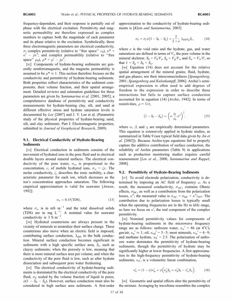
frequency-dependent, and their response is partially out of
phase with the electrical excitation. Permittivity and mag-
netic permeability are therefore expressed as complex
numbers to capture both the magnitude of each parameter
and its phase relative to the excitation. Symbolically, these
three electromagnetic parameters are electrical conductivity,
s; complex permittivity (relative to ‘‘free space’’ e0), k* =k0 � jk00; and complex permeability (relative to ‘‘free
space’’ m0), m* = m0 � jm00.[92] Components of hydrate-bearing sediments are gen-
erally nonferromagnetic, and the magnetic permeability is
assumed to be m* � 1. This section therefore focuses on the
conductivity and permittivity of hydrate-bearing sediments.
Both properties reflect characteristics of the sediment com-
ponents, their volume fraction, and their spatial arrange-
ment. Detailed reviews and estimation guidelines for these
parameters are given by Santamarina et al. [2001, 2005]; a
comprehensive database of permittivity and conductivity
measurements for hydrate-bearing clay, silt, and sand at
different effective stress and hydrate saturation levels is
documented by Lee [2007] and J. Y. Lee et al. (Parametric
study of the physical properties of hydrate-bearing sand,
silt, and clay sediments. Part I: Electromagnetic properties,
submitted to Journal of Geophysical Research, 2009).
9.1. Electrical Conductivity of Hydrate-BearingSediments
[93] Electrical conduction in sediments consists of the
movement of hydrated ions in the pore fluid and in electrical
double layers around mineral surfaces. The electrical con-
ductivity of the pore water, sw, is proportional to the
concentration, c, of mobile hydrated ions, sw = zc. Themolar conductivity, z, describes the ionic mobility, a char-
acteristic parameter for each ion, which decreases as the
ion’s concentration approaches saturation. The following
empirical approximation is valid for seawater [Annan,
1992]:
sw ¼ 0:15 TDSð Þ; ð13Þ
where sw is in mS m�1 and the total dissolved solids
(TDS) are in mg L�1. A nominal value for seawater
conductivity is 3 S m�1.
[94] Hydrated counterions are always present in the
vicinity of minerals to neutralize their surface charge. These
counterions also move when an electric field is imposed,
contributing surface conduction, lddl, to the bulk conduc-
tion. Mineral surface conduction becomes significant in
sediments with a high specific surface area, Ss, such as
clayey sediments; when the porosity is low, meaning that
there is more mineral surface area per volume; and when the
conductivity of the pore fluid is low, such as after hydrate
dissociation and subsequent pore water freshening.
[95] The electrical conductivity of hydrate-bearing sedi-
ments is dominated by the electrical conductivity of the pore
fluid, sf, scaled by the volume fraction of liquid in pores,f(1 � Sh � Sg). However, surface conduction must also be
considered in high surface area sediments. A first-order
approximation to the conductivity of hydrate-bearing sedi-
ments is [Klein and Santamarina, 2003]
sb ¼ sf f 1� Sh � Sg
þ 2
2þ elddlrmSs; ð14Þ
where e is the void ratio and the hydrate, gas, and water
saturations are defined in terms of Vv, the pore volume in the
mineral skeleton: Sh = Vh/Vv, Sg = Vg/Vv, and Sw = Vw/Vv so
that 1 = Sg + Sh + Sw.
[96] Equation (14) does not account for the relative
spatial arrangement of the mineral grains; fluid, hydrate,
and gas phases; nor their interconnectedness [Spangenberg,
2001; Spangenberg and Kulenkampff, 2006]. Archie’s semi-
empirical expression is often used to add degrees of
freedom to the expression in order to describe these
interactions but fails to capture surface conduction
accounted for in equation (14) [Archie, 1942]. In terms of
resistivities, r = 1/s,
1� Sh � Sg
¼ arfrb
fb� �1
c
; ð15Þ
where a, b, and c are empirically determined parameters.
This equation is extensively applied in hydrate studies, as
summarized in Table 9 (see typical field data given by Jin et
al. [2002]). Because Archie-type equations fail to properly
capture the additive contribution of surface conduction, the
reliability of Archie parameters (Table 9) in applications
such as production monitoring studies requires careful
reassessment [Lee et al., 2008; Santamarina and Ruppel,
2008].
9.2. Permittivity of Hydrate-Bearing Sediments
[97] To avoid electrode polarization, conductivity is de-
termined by imposing an AC field of frequency w. As a
result, the measured conductivity, sAC, contains Ohmic
effects, sDC, as well as a contribution from the polarization
losses, k00; the measured value is sAC = sDC + k00e0w. Thecontribution due to polarization losses is typically small
when the operating frequencies are in the Hz to kHz range,
so here we focus on k0, the real component of the complex
permittivity.
[98] Nominal permittivity values for components of
hydrate-bearing sediments in the microwave frequency
range are as follows: unfrozen water, kw0 = 86 (at 4�C);
gas/air, kg0 � 1; oil, koil
0 = 3–5; most minerals, km0 = 4–9;
and methane hydrate, kh0 = 2.5. The polarization of unfro-
zen water dominates the permittivity of hydrate-bearing
sediments, though the permittivity of hydrate may be
significantly higher at lower frequencies. A first approxima-
tion to the high-frequency permittivity of hydrate-bearing
sediments, kb0, is a volumetric linear combination,
k0b ¼ 1� fð Þk0m þ f k0gSg þ k0hSh � k0wSw� �
: ð16Þ
[99] Geometric and spatial effects alter the permittivity of
the mixture. Averaging by traveltime resembles the complex
RG4003 Waite et al.: PHYSICAL PROPERTIES OF HYDRATE-BEARING SEDIMENTS
17 of 38
RG4003

refraction index mixing model albeit assuming lossless
media. In the case of hydrate-bearing sediments, this fre-
quently adopted model becomes
k0b ¼ 1� fð Þffiffiffiffiffiffik0m
pþ f Sg
ffiffiffiffiffik0g
qþ Sh
ffiffiffiffiffik0h
qþ Sw
ffiffiffiffiffiffik0w
p� �h i2: ð17Þ
Equation (17) and similar formulations have been applied to
Gulf of Mexico sediments [Francisca et al., 2005], Mallik
permafrost hydrate field measurements [Lee and Collett,
2005; Sun and Goldberg, 2005], and laboratory measure-
ments [Lee et al., 2008]. Polynomial expressions are also
used [Kliner and Grozic, 2006], and semiempirical
equations developed for unsaturated soils can be adapted
to hydrate-bearing sediments with free gas [Topp et al.,
1980; Wensink, 1993].
9.3. Field-Based Characterization of Hydrate-BearingSediments: Limitations
[100] Either resistivity or permittivity measurements can
be used to distinguish between water and hydrate or other
pore fillers such as gas or ice. Because ionic concentration
has a second-order effect on permittivity but a primary
effect on resistivity, permittivity is a more reliable parameter
to estimate water saturation. For either measurement, hy-
drate saturation is extracted from the volumetric sum 1 = Sh+ Sw + Sg + Sice. The common replacement Sh = 1 � Swpresumes that Sg = 0, which is not true in water-limited
systems or during gas production, and that Sice = 0, which is
not true in permafrost hydrate or during fast pressurization
that results in secondary ice formation.
[101] At the field scale, resistivity-based measurements,
such as the profiles measured by Weitemeyer et al. [2006],
have been used to estimate in situ hydrate saturation. More
commonly, though, electrical measurements are paired with
well log data to provide a more reliable hydrate saturation
estimate, which compliments information gathered from
seismic data (section 10). Examples are provided by Coren
et al. [2001], Guerin and Goldberg [2002], Lee [2002,
2005], Lee and Collett [2006], Ghosh et al. [2006], and
Ellis et al. [2008], among others.
[102] The connection between electrical properties and
hydrate saturation is generally based on Archie’s equation
(equation (15)). As noted in section 9.1 and Table 9, Archie
parameters must be chosen with care. Several pore-scale
characteristics, such as surface conduction and the nature of
the sediment fabric in fine-grained sediments, are either
disregarded or hidden in the Archie parameters [Santamar-
ina and Ruppel, 2008; Spangenberg, 2001].
[103] Anisotropy and spatial heterogeneity, such as in
sediments traversed by networks of hydrate lenses (section
4), add additional difficulty to data interpretation and the
selection of proper models. Consider an example by Lee
and Collett [2009], based on the NGHP-01 study of fine-
grained sediments offshore India [Collett et al., 2008]:
Archie equation–based hydrate saturation estimates using
parameters relevant for homogeneous sediment ranged from
50% to 80% at depths for which pressure cores taken in
nearby wells indicate hydrate saturations are <26% [Lee and
Collett, 2009].
10. SEISMIC WAVE VELOCITY, ATTENUATION,AND SMALL-STRAIN STIFFNESS
[104] Compressional P waves and shear S waves are
extensively used for mapping hydrate occurrences and
estimating the hydrate saturation within those occurrences.
Acoustic remote sensing is possible because the presence of
hydrate stiffens the host sediment, increasing the P and S
wave velocities. This has been comprehensively demon-
strated in hydrate-bearing clay, silt, and sand at different
TABLE 9. Applications of Archie’s Lawa
Site Equation a b c Reference
Blake Ridge(ODP Leg 164)
Sh = 1 � (rsed/rb)1c. The background
resistivity of the fully water saturatedsediment without hydrate is rsed = 0.8495 +(2.986 � 10�4)z (m) for the Blake Ridge.
fb, a, and rfcancel whenrsed/rb iscomputed
fb, a, and rfcancel whenrsed/rb iscomputed
1.9386 Lu and McMechan [2002]
1.05 �2.56 1.9386 Collett and Ladd [2000]Hydrate Ridge(ODP Leg 204)
rf = 0.33 W m, f = 0.65 for GHSZ (CSEM,5 and 15 Hz)
1 �2.8 1.9 Weitemeyer et al. [2006]
rb = arffb = 0.55fb – �1.3 1.9386 Lee and Collett [2006]
>20 mbsf 0.967 �2.81 1.96 Riedel et al. [2006]shallow 1.35 �1.76 1.96 Riedel et al. [2006]
Mallik rf = 0.56 (z = 738.23 m), rf = 0.27(z = 1141.02 m)
0.62 �2.15 1.9386 Lee and Collett [2005],Guerin and Goldberg [2002],and Reister [2003]
Cascadia margin/Makran region
rf = 1/(3 + T (�C)/10) 1 �2.8 1.9 Ghosh et al. [2006]
Vancouver island rf = (Csw/Cf)rsw, where Csw is salinity ofthe seawater reference and Cf is salinityof the in situ fluid
1.4 �1.76 1.76 Hyndman et al. [1999]
Milne Point, NorthSlope of Alaska
arf = 1 W m – �2.15 1.9386 Lee [2005]
rf = 3 W m, 0.5 < a < 2.5, �3 < b < �1.5 1 �2 2 Edwards [1997]aGeneral form for no gas phase Sg = 0: Sw = [a(rf /rb)f
b]1c or Sh = (1 � Sw) = 1 � [a(rf /rb)f
b]1c. Sh = Vh/Vv, Sg = Vg /Vv, Sf = Vf /Vv, and 1 = Sg + Sh + Sf.
GHSZ, gas hydrate stability zone; ODP, Ocean Drilling Program. The cautious use of these parameters is suggested by Santamarina and Ruppel [2008].
RG4003 Waite et al.: PHYSICAL PROPERTIES OF HYDRATE-BEARING SEDIMENTS
18 of 38
RG4003
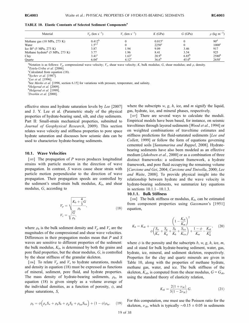
effective stress and hydrate saturation levels by Lee [2007]
and J. Y. Lee et al. (Parametric study of the physical
properties of hydrate-bearing sand, silt, and clay sediments.
Part II: Small-strain mechanical properties, submitted to
Journal of Geophysical Research, 2009). This section
relates wave velocity and stiffness properties to pore space
hydrate saturation and discusses how seismic data can be
used to characterize hydrate-bearing sediments.
10.1. Wave Velocities
[105] The propagation of P waves produces longitudinal
strains with particle motion in the direction of wave
propagation. In contrast, S waves cause shear strain with
particle motion perpendicular to the direction of wave
propagation. Their propagation speeds are controlled by
the sediment’s small-strain bulk modulus, Kb, and shear
modulus, G, according to
Vp ¼
ffiffiffiffiffiffiffiffiffiffiffiffiffiffiffiffiffiffiKb þ
4
3G
rb
vuut;
Vs ¼ffiffiffiffiffiG
rb
r;
ð18Þ
where rb is the bulk sediment density and Vp and Vs are the
magnitudes of the compressional and shear wave velocities.
Differences in their propagation modes mean that P and S
waves are sensitive to different properties of the sediment:
the bulk modulus, Kb, is determined by both the grains and
pore fluid properties, but the shear modulus, G, is controlled
by the shear stiffness of the granular skeleton.
[106] To relate Vp and Vs to hydrate saturations, moduli
and density in equation (18) must be expressed as functions
of mineral, sediment, pore fluid, and hydrate properties.
The mass density of hydrate-bearing sediments, rb, in
equation (18) is given simply as a volume average of
the individual densities, as a function of porosity, f, andphase saturations, S,
rb ¼ f rwSw þ rhSh þ rgSg þ riceSice� �
þ 1� fð Þrm; ð19Þ
where the subscripts w, g, h, ice, and m signify the liquid,
gas, hydrate, ice, and mineral phases, respectively.
[107] There are several ways to calculate the moduli.
Empirical models have been based, for instance, on seismic
traveltimes through layered sediments [Wood et al., 1994] or
on weighted combinations of traveltime estimates and
stiffness predictions for fluid-saturated sediments [Lee and
Collett, 1999] or follow the form of equations governing
cemented soils [Santamarina and Ruppel, 2008]. Hydrate-
bearing sediments have also been modeled as an effective
medium [Jakobsen et al., 2000] or as a combination of three
distinct frameworks: a sediment framework, a hydrate
framework, and pore fluid occupying the remaining volume
[Carcione and Gei, 2004; Carcione and Tinivella, 2000; Lee
and Waite, 2008]. To provide physical insight into the
relationship between hydrate and the wave velocity in
hydrate-bearing sediments, we summarize key equations
in sections 10.1.1–10.1.3.
10.1.1. Bulk Stiffness[108] The bulk stiffness or modulus, Kb, can be estimated
from component properties using Gassmann’s [1951]
equation,
Kb ¼ Ksk þ1� Ksk
Km
� �2
fSw
Kw
þ Sg
Kg
þ Sh
Kh
þ Sice
Kice
� �þ 1� f
Km
� Ksk
K2m
; ð20Þ
where f is the porosity and the subscripts b, w, g, h, ice, m,
and sk stand for bulk hydrate-bearing sediment, water, gas,
hydrate, ice, mineral, and sediment skeleton, respectively.
Properties for the clay and quartz minerals are given in
Table 10, along with the properties of methane hydrate,
methane gas, water, and ice. The bulk stiffness of the
skeleton, Ksk, is computed from the shear modulus, G = Gsk,
using the standard theory of elasticity relation,
Ksk ¼2 1þ nskð Þ3 1� 2nskð ÞG: ð21Þ
For this computation, one must use the Poisson ratio for the
skeleton, nsk, which is typically �0.15 ± 0.05 in sediments
TABLE 10. Elastic Constants of Selected Sediment Componentsa
Material Vp (km s�1) Vs (km s�1) K (GPa) G (GPa) r (kg m�3)
Methane gas (10 MPa, 273 K) 0.412b 0 0.015c 0 90d
Water 1.5e,f 0 2250e 0 1000e
Ice Ihg (5 MPa, 273 K) 3.87 1.94 9.09 3.46 917Methane hydrateg (5 MPa, 273 K) 3.77 1.96 8.41 3.54 925Clay 3.41c 1.63c 20.9h 6.85h 2580h
Quartz 6.04c 4.12c 36.6h 45.0h 2650i
aNotation is as follows: Vp, compressional wave velocity; Vs, shear wave velocity; K, bulk modulus; G, shear modulus; and r, density.bEstela-Uriba et al. [2006].cCalculated from equation (18).dSychev et al. [1987].eLee et al. [1996].fSee Mavko et al. [1998, section 6.15] for variations with pressure, temperature, and salinity.gHelgerud et al. [2009].hHelgerud et al. [1999].iDvorkin et al. [2000].
RG4003 Waite et al.: PHYSICAL PROPERTIES OF HYDRATE-BEARING SEDIMENTS
19 of 38
RG4003

with hydrate saturations Sh < 40% and may increase to nsk� 0.3 for sediments with Sh > 60%.
[109] It follows from equation (20) that the presence of
free gas (Kg� Kw, Kh, and Km) has a pronounced effect in
decreasing the bulk stiffness, Kb, and the longitudinal wave
velocity, Vp (Figure 9). The decrease in bulk density is
minor in comparison. Even at very low gas saturations, the
presence of gas causes Vp to rapidly approach �1.5Vs.
10.1.2. Shear Stiffness Dependence on Hydrate Habitin Pore Space[110] The presence of hydrate can alter the stiffness of
both the pore fluid and sediment skeleton. The pore fluid
stiffening impacts only the bulk modulus and is accounted
for by the second term in equation (20). Skeletal stiffening
increases the shear modulus, which, in turn, increases the
skeletal bulk modulus as shown in equation (21). In
hydrate-free sediment, shear stiffness is controlled by the
mean effective stress, s0 (kPa),
G ¼ as0
1 kPa
� �b
; ð22Þ
where a is the shear stiffness when s0 = 1 kPa and brepresents the sensitivity of G to effective stress. Parameters
a and b depend on the sediment’s granular packing and
fabric properties, as well as the nature of the intergranular
contacts [Santamarina et al., 2001].
[111] In the presence of hydrate, the estimation of shear
stiffness must also take into consideration pore space hydrate
saturation, Sh, and where hydrate forms in the pore space.
10.1.2.1. Pore Filling[112] The presence of hydrate does not affect the shear
stiffness, which remains controlled by effective stress
(equation (22)). Hydrate formers dissolved in water tend
to promote pore-filling hydrate growth at low Sh that
becomes load-bearing hydrate as Sh exceeds 25%–40%
[Berge et al., 1999; Yun et al., 2005, 2007].
10.1.2.2. Load Bearing[113] Load-bearing hydrate increases shear stiffness, but
grain contact stiffness continues to reflect the state of
effective stress (equation (22)). The relevance of effective
stress decreases as hydrate saturation increases.
10.1.2.3. Cementation[114] Hydrate formation at grain contacts readily takes
over from effective stress as the primary control of the
skeletal stiffness [Dvorkin et al., 1999, 2000; Fernandez and
Santamarina, 2001; Guerin et al., 1999; Xu et al., 2004].
10.1.3. Predicting Hydrate Saturations From WaveVelocities[115] The dependence of skeletal stiffness G = Gsk and
Ksk, and hence wave velocity, on the pore space location of
hydrate causes ambiguity when trying to infer hydrate
saturations from measured wave velocities: the anomalously
high interval wave velocity in Figure 9 could be due to a
small amount of hydrate cementing sediment grains, a
medium amount of hydrate supporting a portion of the
sediment load, a large volume of hydrate floating in the
pore space (see Figure 10), or some combination thereof.
[116] The combined interpretation of compressional and
shear wave velocity data, together with directional resistiv-
ity measurements to characterize the anisotropy in fracture-
dominated systems (see sections 4 and 9.3), can help reduce
this ambiguity. Field measurements of shear wave velocity
remain difficult, however, and even well log measurements
of shear wave velocity can be untrustworthy [Dai et al.,
2008a; Lee and Waite, 2008].
[117] Seafloor compliance measurements, which provide
a direct measure of the elastic deformation of the seafloor in
response to passing waves on the ocean surface [Willoughby
et al., 2008], and controlled source electromagnetic surveys
which measure electrical resistivity in sediment via detec-
tors towed along the sediment surface [Ellis et al., 2008;
Weitemeyer et al., 2006; Yuan and Edwards, 2000] can also
provide independent elastic and electrical measures for the
estimation of the in situ hydrate volumes.
[118] An independent estimate of in situ elastic properties
at a given location can anchor, and thereby improve, the
accuracy of seismic inversions in which elastic properties
and hydrate saturations are estimated over broad regions
[Inks et al., 2008; Jones et al., 2008]. The inversion,
described in detail by Xu et al. [2004] and Dai et al.
[2008b], seeks to build a model of the local geology such
that synthetic seismic waveforms sent through the model
space mimic the seismic waveforms measured in the field.
The map of physical properties provided by the inversion is
converted to a map of hydrate saturation by assuming a pore
space hydrate configuration.
10.2. Attenuation
[119] Attenuation is a measure of energy loss as waves
travel from a source to a sensor and is affected by hydrate
Figure 9. Effect of gas hydrate and free gas on measuredin situ wave velocities for Ocean Drilling Program Site 889in the Cascadian subduction zone offshore Vancouver,Canada (adapted from Yuan et al. [1996]). Relative to theregional ‘‘hydrate-free’’ velocity profile with depth (solidcurve [from Yuan et al., 1996]), VSP interval wavevelocities [MacKay et al., 1995] are elevated in thepresence of hydrate. Below the bottom simulating reflector(BSR), where free gas is present rather than hydrate, thewave velocity falls below the water-saturated sedimentwave velocity trend.
RG4003 Waite et al.: PHYSICAL PROPERTIES OF HYDRATE-BEARING SEDIMENTS
20 of 38
RG4003

saturation [Chand and Minshull, 2004; Dvorkin and Uden,
2004; Guerin and Goldberg, 2005; Guerin et al., 2005].
Unfortunately, measuring the ‘‘intrinsic attenuation’’ of
hydrate-bearing sediment is hindered by the prevailing
effects of geometric spreading and impedance mismatches
in spatially heterogeneous media [Huang et al., 2009]. For
example, acoustic energy from borehole sources can reflect
off the borehole wall due to the high stiffness of hydrate-
bearing sediments and not propagate through the hydrate-
bearing sediment at all [Lee and Waite, 2007]. Even if the
intrinsic attenuation in sediment could be properly estimated
in the field, its interpretation is made more difficult by the
multiple coexisting energy loss mechanisms in sediments
[Wang and Santamarina, 2007] which are further altered by
the presence of hydrates in the pore space [Lee, 2006;
Matsushima, 2006].
[120] Attenuation and wave velocity dispersion are caus-
ally related, as indicated by the Kramers-Kronig relations
[e.g., Toll, 1956; Wang and Santamarina, 2007]. As dis-
cussed by Lee [2006], however, with the exception of the
Guerin and Goldberg [2005] model, published attenuation
models tend to treat attenuation and wave velocities inde-
pendently, which can lead to predictions of unphysical
behavior. These challenges have limited the reliability of
attenuation as a tool for estimating in situ hydrate saturations.
11. STRENGTH AND DEFORMATION
[121] Sediment strength and the extent to which sediment
deforms under a load are critical inputs for the analysis of
potential failures around wells [Masui et al., 2008; Rutqvist
and Moridis, 2007] and for evaluating seafloor stability
over larger length scales [Nixon and Grozic, 2007; Sultan et
al., 2004a].
11.1. Definition of Strength and DeformationParameters
[122] Sediment strength is a combination of the cohesive
resistance, c, and effective stress–dependent frictional
resistance described by the friction angle, F, which includes
resistance to sliding between particles, particle rearrange-
ment, and particle crushing. The two contributions to shear
strength are captured in the Coulomb failure criterion which
relates the shear stress at failure, tf, to the normal effective
stress, sn0, acting on the failure plane,
tf ¼ cþ s0n tanF: ð23Þ
This failure criterion plots as a straight line in t � sn0 space.
The state of stress at a point in equilibrium within the test
sample plots as a circle in t � sn0 space called theMohr circle
of stress. The sediment reaches failure when the Mohr circle
becomes tangent to the Coulomb failure envelope (Figure 11).
11.2. Laboratory Measurements
[123] The strength parameters c and F can be measured in
the laboratory using triaxial compression tests [ASTM
Figure 11. Mohr-Coulomb failure diagram. Within asample subjected to the principal effective stresses s1
0 ands30, the state of stress falls on a Mohr circle in t � sn
0 space.Shear failure occurs when the Mohr circle becomes tangentto the Coulomb failure line, meaning that the shear stressalong the failure plane, tf, exceeds the combined resistanceof cohesion, c, and friction, sn
0tanF. The friction angle, F,and failure plane angle, a, are related by a = 45� + F/2.
Figure 10. Comparison between field (open symbols),laboratory (solid symbols), and modeling results (solid anddashed curves) for (a) compressional and (b) shear wavevelocities in hydrate-bearing sediments. Modeling resultsare from Kleinberg and Dai [2005]. Dot-dashed curvesrepresent wave velocities for hydrate forming as cement atgrain contacts. Particularly for low hydrate saturations, thisdistribution most significantly increases the wave velocity.Dashed curves predict wave velocities for hydrate that coatsand cements sediment grains. Solid curves represent load-bearing hydrate, and dotted curves show the impact of pore-filling hydrate. Pore-filling distributions begin bridgingsediment grains and behaving as load-bearing distributionsfor Sh > �25%–40%.
RG4003 Waite et al.: PHYSICAL PROPERTIES OF HYDRATE-BEARING SEDIMENTS
21 of 38
RG4003

Standard, 2004, 2006] in which a cylindrical specimen is
subjected to an effective confining stress s30 = s3 � Pp and
then brought to failure by increasing the axial effective
stress s10 = s1 � Pp (Figure 11, inset). Triaxial test data
obtained at different effective confining stress levels are
combined to define the linear Coulomb failure envelope
from which c and F are derived. Tests are generally run in
either a drained mode, in which the pore pressure is
maintained independently from the applied stress, or in an
undrained mode, in which drainage of neither gas nor liquid
pore fluid from the specimen is allowed and hence the pore
pressure changes as the sample deforms. The specimen
volume is assumed constant during undrained tests in
water-saturated soft sediments, though this will not be the
case in hydrate-bearing sediments if free gas forms during
the test.
[124] Triaxial tests also provide prefailure information
that can be used to determine Young’s modulus, E; Pois-
son’s ratio, n; and dilatancy angle, y. Values of E and n are
often reported at 50% of the failure load, E50 and n50. Thedilatancy angle measures the rate of volume increase with
increasing shear strain. Dilative sediment subjected to
undrained shear will experience a decrease in pore fluid
pressure, thereby increasing the normal effective stress and
sediment strength (equation (23)); the decrease in fluid
pressure may cause gas dissolution and hydrate dissociation.
[125] When pores are interconnected, pore fluid pressure
can be monitored or controlled independently of the con-
fining stress in drained tests, and data are best interpreted
within the framework of effective stresses, for which the
pore pressure is subtracted from the applied stresses. The
effective stress can be increased by either increasing the
total stress under constant pore pressure or decreasing the
pore pressure under constant total stress. Both should result
in the same volume change for a given change in effective
stress; however, decreasing the pore fluid pressure may lead
to hydrate dissociation if reduced below the stability pres-
sure at the test temperature. Once pores are occluded and
therefore isolated from the external pore fluid reservoir, the
local pore pressure evolves in response to the applied total
stress and is not measurable using sensors outside the
sample. Only the total stresses are known, restricting data
analysis to a total stress framework.
11.3. General Trends
[126] The presence of methane hydrate increases stiffness,
enhances prefailure dilation, and leads to higher strength.
Figure 12 illustrates shear resistance and dilation mechanisms
occurring at different levels of hydrate saturation in the pore
space. Hydrate saturation is considered low for the purposes
of shear strength when Sh < �30% and high when Sh > 40%.
Conditions above Sh = 70%–80% are unusual and involve
occluded pores inside the sediment. Specific results for
coarse-grained sediment are given in sections 11.3.1 and
11.3.2, and fine-grained sediments are discussed in section
11.3.3. Further details are given by Soga et al. [2006].
Figure 12. Mechanisms controlling the shear strength of hydrate-bearing sediments. Sediment grainsare white circles, hydrate is black, and water is blue (modified from Yun et al. [2007]). Effective stressmeasurements are preferred when interpreting shear behavior, but at high hydrate saturations for whichpressure in the occluded pores cannot be measured, interpretations must be based on total stressmeasurements.
RG4003 Waite et al.: PHYSICAL PROPERTIES OF HYDRATE-BEARING SEDIMENTS
22 of 38
RG4003

11.3.1. Coarse-Grained Soils: Drained Tests[127] The measured stress-strain responses of natural
hydrate-bearing sandy sediments retrieved from the Nankai
Trough are shown in Figure 13 as a function of pore space
hydrate saturation [Masui et al., 2006]. In agreement with
previous observations (Figure 12), the peak strength, E50,
and dilation generally increase with hydrate saturation [see
also Hyodo et al., 2007]. The Poisson’s ratio, n50, variesbetween 0.10 and 0.19, with no apparent relationship to
hydrate saturation.
[128] Effective stress strength parameters can depend
strongly on the hydrate formation history (refer to section 3).
There is a pronounced increase in strength and stiffness
(Figure 14) as well as dilation angle (Figure 15b) when even
a small amount of hydrate forms at interparticle contacts and
cements particles together. In contrast, pore-filling hydrate
begins to have a measurable effect on these parameters only
when the hydrate saturation exceeds about Sh � 30%.
However, neither the friction angle nor the cohesion depend
strongly on the mode of hydrate occurrence, and friction
angle is nearly independent of hydrate saturation as well. It
should be noted that the data were gathered from tests run at
1 MPa effective confining pressure; lower dilation is
expected at higher confining pressures.
11.3.2. Coarse-Grained Soils: Undrained Tests[129] Undrained triaxial test data show congruent trends
to those gathered in drained tests. Gas hydrate–bearing
sands from the Mackenzie Bay (Mallik 2L-38 between
depths of 898 and 913 m, under 640 m of permafrost)
exhibit a higher dilative tendency than the same sediments
without hydrates (Figure 16) and are correspondingly stron-
ger and stiffer. Similar conclusions are reached in undrained
triaxial tests run on THF hydrate-bearing sands and silts at
different stress levels and hydrate saturations [Yun et al.,
2007]; this study reached Sh = 100% and found that stiffness
and undrained strength are determined by the hydrate phase
in high hydrate saturation sediments rather than by the
initial effective confining stress.
[130] In summary, available data show that (1) stiffness,
cohesion, and dilation increase and friction angle remains
constant as hydrate concentration increases; (2) at hydrate
saturation Sh < 30%, cementing hydrate has a more pro-
nounced effect than pore-filling hydrate on mechanical
properties; (3) formation history effects gradually diminish
at high hydrate saturation; and (4) the initial effective stress
loses relevance at very high hydrate concentrations, in
which case the hydrate phase controls the strength and
deformation characteristics.
11.3.3. Fine-Grained Soils[131] Hydrate-bearing fine-grained soils have not been
extensively studied due to a lesser interest from a resource
potential perspective, coupled with difficulties in hydrateFigure 13. Dependence of stress (solid curves) andvolumetric strain (dashed curves) on axial strain for fourmethane hydrate-bearing sands [Masui et al., 2006]. Thedilation angle, y, can be calculated from the slope of thevolumetric strain as shown.
Figure 14. (a) Peak strength and (b) Young’s modulus at50% of the stress at failure, E50, versus methane hydratesaturation. Cementing hydrate samples show significantimpact of hydrate at low hydrate saturations, Sh. Pore-fillinghydrate does not significantly impact peak strength or E50
until Sh exceeds 25%. The offset between the two studies isdue to the 3 MPa confining pressure used by Ebinuma et al.[2005] compared to the 1 MPa confining pressure used byMasui et al. [2005].
RG4003 Waite et al.: PHYSICAL PROPERTIES OF HYDRATE-BEARING SEDIMENTS
23 of 38
RG4003

formation and in mechanical testing. Therefore, limited
data are available, and further work is needed to understand
the mechanical behavior of hydrated bearing fine-grained
sediments.
[132] Undrained, triaxial test data gathered for THF
hydrate disseminated in Kaolinite clay and precipitated silt
in which each silt grain is an agglomerate are summarized in
Figure 17 [Yun et al., 2007]. Specimens without hydrate
exhibit a frictional, linear increase in undrained shear
strength as the initial effective confining stress increases.
In high hydrate saturation sediments, however, the un-
drained shear strength is insensitive to effective confining
stress. The undrained modulus E50 follows a similar trend.
[133] Undrained shear strengths of natural fine-grained
sediments with hydrate have been measured using a small
cone-shaped penetrometer in pressure cores recovered in the
Gulf of Mexico [Yun et al., 2006]. These specimens were
maintained at the in situ fluid pressure but with virtually no
effective stress. The measured undrained strength therefore
indicates only the in situ effects of hydrate and the granular
porosity of these fine-grained sediments rather than the
combined impact of hydrate, porosity, and effective stress.
In all cases, undrained strength was higher in the hydrate-
bearing sediments than in sediments without hydrates at the
same burial depth [Yun et al., 2006]. In situ cone resistance
and friction during piezocone deployments offshore Nigeria
also show an increased strength in the presence of hydrate
[Sultan et al., 2007]. These measurements are limited to
shallow sediments (less than �30 mbsf), however.
12. VOLUME CHANGE UPON DISSOCIATION
[134] Hydrate dissociation reduces the solid hydrate vol-
ume, produces gas and water, and decreases the water
salinity. Depending on boundary conditions, these changes
produce one or both of the following: (1) variations in the
pore fluid pressure and effective stress and (2) changes in
the volume occupied by the sediment.
[135] In natural settings, volume contraction typically
follows hydrate dissociation once the initial pressure in-
crease due to gas produced during dissociation dissipates.
The magnitude of contraction depends on the soil type, the
current in situ state of stress and the stress state when
hydrate formed, the distribution of hydrate within the
sediment, and the current mineral porosity defined in terms
Figure 15. (a) Cohesion and friction angle and (b) dilationangle versus hydrate saturation in natural methane hydratesamples (solid symbols) [Masui et al., 2006; Soga et al., 2006]and laboratory-formed cemented methane hydrate samples(open symbols) [Masui et al., 2005]. Though cohesion anddilation angle increase with increasing hydrate saturation(solid trend lines through the cementing hydrate data),friction angle is largely independent of hydrate saturation(dotted trend line).
Figure 16. Dependence of (a) peak shear stress and(b) pore pressure change on pore content and axial strain incoarse sands recovered from the Mallik 2L-38 permafrostresearch well. Hydrate-free samples (broken curves) weresheared after the gas hydrate dissociated, and the hydrate-bearing sample (solid curve) was sheared with hydrate butno ice present [after Winters et al., 2002].
RG4003 Waite et al.: PHYSICAL PROPERTIES OF HYDRATE-BEARING SEDIMENTS
24 of 38
RG4003

of (VT � Vm)/VT, where Vm is the volume of minerals and VT
is the total volume.
[136] Very limited data have been gathered for volume
changes upon dissociation of hydrate-bearing sediments.
However, there are data for similar processes that can
provide useful insight to help constrain design parameters,
such as the literature on cold regions engineering, which
contains a wealth of data on material characterization and
the effect of freeze-thaw cycles [Gatto et al., 2001]. In
particular, frozen ground characterization schemes can
prove helpful in assessing hydrate-bearing sediments that
are most susceptible to volume change.
[137] Several volume loss mechanisms are identified in
the context of hydrate dissociation in sediments [Lee et al.,
2009]: (1) bulk hydrate dissociation, (2) sediment skeleton
alteration, (3) consolidation, and (4) sand production. These
mechanisms are briefly described in sections 12.1–12.4.
12.1. Contraction due to Bulk Hydrate Dissociation
[138] Segregated bulk hydrate exists in sediments in the
form of lenses, veins, or nodules that are much larger than
the pore size (e.g., Figure 4). The dissociation of bulk
hydrate creates a void volume, Vv, equal to the hydrate
volume, Vh. The upper bound estimate of the macroscale
volumetric strain, evol, is equal to the void volume, Vv = Vh,
divided by the initial total volume of the sediment, VT;
therefore, evol � (Vh/VT).
[139] Secondary mechanisms such as arching, in which
the stress is transferred away from yielding sediment, or
raveling, in which sediment collapses into void spaces,
reduce the impact of void formation on volume change. In
such cases, a reduction factor 0 � b � 1.0 can be used to
decrease the estimated upper bound volumetric strain,
evol ¼ bVh
VT
: ð24Þ
The value of b is a function of the amount, size, and
geometry of the bulk hydrate, along with the soil stiffness,
strength, and state of stress. Though b could exceed 1.0 in
very loose sediments when hydrate dissociation leads to
volume collapse in the neighboring sediment, it is within the
0.2–0.4 range for most hydrate-bearing sediments.
12.2. Contraction due to Disseminated HydrateDissociation
[140] Disseminated hydrate within the intergranular pore
space of the sediment can contribute to stiffening of the
granular structure and can even carry part of the load (see
sections 3, 10, and 11). Hydrate dissociation causes fabric
changes such that the granular skeleton continues sustaining
the applied effective stresses state. The consequence of this
fabric alteration is either volume contraction or stress
relaxation, depending on boundary conditions.
[141] The volumetric strain at constant boundary stresses
is a function of the degree of hydrate saturation and
distribution within the pore space, the soil compressibility,
and the in situ state of stress. A comprehensive study
conducted with various sediments, stress levels, and both
50% and 100% THF hydrate saturation is reported by Lee
[2007] and Lee et al. [2007]; complementary data gathered
with Gulf of Mexico sediments are given by Lee et al.
[2008]. Results indicate the volumetric strain due to hydrate
dissociation decreases as the effective stress increases,
meaning less contraction should be expected in deeper
sediments.
12.3. Contraction due to Increased Effective Stress:Depressurization
[142] Methane can be produced from hydrate-bearing
sediments by reducing the pore fluid pressure by an amount
DP that brings the system to the boundary of hydrate
stability. There is a corresponding increase in effective
stress state, and sediment compaction follows. In a one-
dimensional system, the vertical strain, ez, is equal to the
volumetric strain, evol, and can be computed as
ez ¼ evol ¼Cc
1þ e0log
s0z0 þDP
s0z0
� �; ð25Þ
Figure 17. Undrained shear strength versus initial effec-tive confining stress at different hydrate saturations fordifferent soils: (a) Kaolinite and (b) precipitated silt [afterYun et al., 2007]. With increasing tetrahydrofuran hydratesaturation, the dependence of shear strength on effectivestress diminishes (dotted trend lines).
RG4003 Waite et al.: PHYSICAL PROPERTIES OF HYDRATE-BEARING SEDIMENTS
25 of 38
RG4003

where Cc is the sediment compressibility, e0 is the initial
void ratio, and sz00 is the initial vertical effective stress. The
parameter Cc can be estimated from sediment properties
(Table 5).
[143] Case histories for subsidence due to the depressur-
ization of aquifers during water or hydrocarbon removal
show that surface subsidence estimates must account for
three processes: (1) the reservoir response, which is gener-
ally nonlinear, time-dependent, and spatially variable; (2) the
behavior of the upper layers, including sediment stiffness,
shear-induced volume changes, and time-dependent defor-
mation processes; and (3) geometric-mechanical interaction
effects, including reservoir thickness, thickness of the
overlying sediment column, spatial extent of production,
and production history [Atkinson and Pedersen, 1998;
Chan, 2005; Geertsma, 1973; Siriwardane, 1992; Sorey et
al., 1993; Sylte et al., 1999; Xu et al., 2001; Yerkes and
Castle, 1970].
12.4. Contraction due to Mineral Migration andRemoval
[144] Volume loss associated with the transport of mineral
particles out of the sediment and into the well can be an
important volume contraction mechanism, particularly in
sandy sediments. Sand production is facilitated by hydrate
dissociation and mixed fluid flow conditions. The potential
volume loss depends on flow rates, the geometry of the
layer, and soil type.
12.5. Additional Consequences of VolumeContraction
[145] Compaction is not the only effect associated with
hydrate dissociation. There is evidence that the horizontal
effective stress also decreases during dissociation and that
the sediment can reach internal shear failure conditions
[Shin and Santamarina, 2009]. In geomechanical terms,
the stress ratio at rest, ko, decreases toward Rankine’s active
Earth pressure coefficient, ka, defined as the minimum
lateral effective stress for soils at their extensional failure
condition. In strain-softening sediments, this situation may
lead to the formation of shear planes within the sediment
[Shin et al., 2008].
13. FUTURE RESEARCH DIRECTIONS IN THECHARACTERIZATION OF HYDRATE-BEARINGSEDIMENTS
[146] Particle and pore-scale interactions between hydrate
and its host sediment lead to a richly complex system of
interdependent macroscale physical properties that govern
the evolution of hydrate-bearing sediments. Understanding
these interdependencies can provide a framework for un-
derstanding hydrate-bearing sediments as well as providing
a robust basis for preliminary evaluations of gas production
strategies and instability conditions, such as slope and
borehole failures.
[147] The three most relevant properties for predicting the
behavior of hydrate-bearing sediments are the pore space
hydrate saturation, effective stress, and sediment grain size,
particularly the content of fine-grained silts and clays. These
parameters must be explicitly assessed and reported in all
future studies.
[148] Above 25%–40% pore space hydrate saturation,
hydrate behaves as a load-bearing member of the sediment,
decreasing the permeability while increasing sediment stiff-
ness and strength. As the hydrate saturation decreases,
effective stress becomes the primary control on sediment
stiffness and strength. The influence of hydrate on the host
sediment properties can be subtle at low saturations, and
fewer measurements have been made on these systems
relative to the highly hydrate-saturated sands. The low-
saturation case must nevertheless be examined because,
for instance, the dissociation of small quantities of hydrate
can still have pronounced effects on pore fluid pressure,
effective stress, and stability conditions.
[149] The host sediment’s silt and clay content, the fines,
determines the mode of hydrate occurrence. In coarse-
grained systems with a fines content below �7%, hydrate
generally occurs in the pore space between grains. When the
fines content exceeds �15%, hydrate is found disseminated
in the sediment and forming veins and nodules that displace
sediment grains. As a result, pronounced spatial variability
is common in the fine-grained sediments that host the
majority of the Earth’s hydrate. Fines content also deter-
mines fluid permeability and plays a critical role in sediment
evolution after hydrate dissociation. Future studies should
further explore the effect of the amount of fines, their
mineralogy, and specific surface area on the characteristics
of hydrate-bearing sediments.
[150] The structure of hydrate-bearing sediments com-
prises the sediment fabric and the hydrate distribution at the
pore scale. Both structural characteristics can be modified
by changes in effective stress, fluid pressure, and/or tem-
perature. Sampling and core extraction inherently modify
the effective stress and physical state of sediments and may
also cause hydrate dissociation. Therefore, emphasis must
be placed on further developing comprehensive in situ
sediment characterization through borehole logging tools
that incorporate the simultaneous measurements of multiple
properties from the minimally disturbed material surround-
ing the probe. For measurements that cannot be made in a
borehole, the advent of routine pressure coring and the
testing of such cores at their in situ pore pressure is
invaluable. A key advance would be to maintain or quickly
reinstate the in situ effective stresses.
[151] Laboratory studies using synthetic specimens at-
tempt to emulate field conditions while avoiding core
disturbance problems. The importance of emulating the
noncementing methane hydrate observed in most marine
field studies highlights the need to develop reproducible
hydrate formation techniques, likely involving dissolved
phase methane, that avoid the cementing nature of methane
hydrate formed in the presence of free gas.
[152] Field and laboratory specimens tend to exhibit
marked heterogeneity. Future experimental studies should
routinely image specimens to visualize hydrate distribution
RG4003 Waite et al.: PHYSICAL PROPERTIES OF HYDRATE-BEARING SEDIMENTS
26 of 38
RG4003

so that proper data inversion procedures can be imple-
mented in the interpretation of measured properties.
NOTATION
The following subscripts, used throughout the paper,refer a parameter to a particular material or condition:
b bulk material, including all constituents.f pore fluid.g gas.h hydrate.m sediment grain mineral.
max maximum value.min minimum value.
s solid sediment constituents.T total value, including all constituents.v void space or pore space.w water.
Parameters given below are listed in SI units. Whenapplicable, common usage units are given in the main text.
Section 2: solubility
aij activity of species i in phase j (unitless).fij fugacity of species i in phase j (Pa).fi0 fugacity of species i in a convenient reference state
(Pa).G Gibbs free energy (J).H superscript referring to the hydrate phase.L superscript referring to the liquid phase.m molality (moles of solute per kilogram of solvent).M molarity (moles of solute per liter of solution).nij number of moles of species i in phase j (mol).
Pi pressure in species i (Pa).r interfacial radius of curvature (m).R universal gas constant (8.314 J (mol K)�1).T temperature (K).xij concentration of species i in phase j (mole fraction).b superscript referring to hypothetical empty hydrate
phase with no guest molecules.gi,w interfacial tension between species i and water
(N m�1).DP capillary pressure (Pa).mij chemical potential of species i in phase j (J mol�1).
mi0 chemical potential of species i in a convenient
reference state (J mol�1).nij activity coefficient of species i in phase j (unitless).
Section 3: formation history
Sh hydrate saturation in the pore space (% or unitless).
Section 4: spatial variability
Vp compressional wave velocity (m s�1).Vs shear wave velocity (m s�1).
Section 5: sampling and handling effects
Gmax small-strain shear stiffness (Pa).PI plasticity index (% or unitless).
Section 6: index properties
Cc coefficient of compressibility (unitless).Ccurv coefficient of curvature (unitless).CH Hazen’s empirical coefficient (�1 � 104 (m s)�1)
[Carrier, 2003].Cunif coefficient of uniformity (unitless).DX grain diameter at which X% of the sample is finer
(m).e void ratio (unitless).
Gs specific gravity (unitless).K hydraulic conductivity (m s�1).LI liquidity index (% or unitless).LL liquid limit (% or unitless).M mass (kg).PI plasticity index (% or unitless).PL plastic limit (% or unitless).R particle roundness (unitless).Sh hydrate saturation in the pore space (% or unitless).Ss specific surface (m2 kg�1).Su undrained shear strength (Pa).V volume (m3).w gravimetric water content, with respect to the
specimen’s mineral mass (unitless).gw unit weight of water (N m�3).q shape and tortuousity factor (unitless).m dynamic fluid viscosity (Pa s).r mass density (kg m�3).
sv0 mean effective stress at failure (Pa).f porosity (% or unitless).
Fcv friction angle during constant volume shear (degreesor radians).
Section 7: thermal properties
cp specific heat (J (kg K)�1).m cementation exponent (2 ± 0.5 for granular media,
unitless) [Revil, 2000].P pressure (Pa).R universal gas constant (8.314 J (mol K)�1).Sh hydrate saturation in the pore space (% or unitless).T temperature (K).Z nonideal gas compressibility factor (unitless).
DH enthalpy of reaction (J mol�1).k thermal diffusivity (m2 s�1).l thermal conductivity (W (m K)�1).r mass density (kg m�3).f porosity (% or unitless).
Section 8: permeability and fluid flow
A cross-sectional area (m2).C gas slippage or Klinkenberg effect parameter
(unitless).DX grain diameter at which X% of the sample is finer
(m).e void ratio (unitless).g acceleration due to gravity (9.8 m s�2).k intrinsic permeability (m2).kr relative permeability (unitless).l length (m).n van Genuchten curve-fitting parameter (unitless).P pressure (Pa).
RG4003 Waite et al.: PHYSICAL PROPERTIES OF HYDRATE-BEARING SEDIMENTS
27 of 38
RG4003
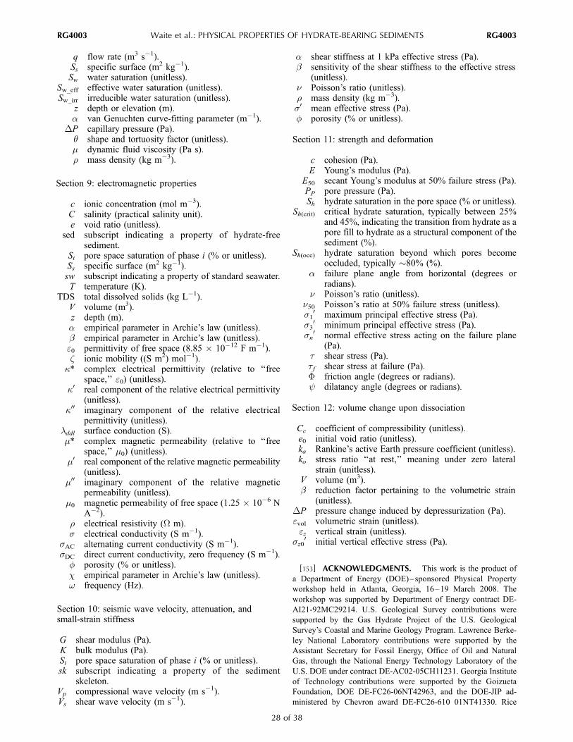
q flow rate (m3 s�1).Ss specific surface (m2 kg�1).Sw water saturation (unitless).
Sw_eff effective water saturation (unitless).Sw_irr irreducible water saturation (unitless).
z depth or elevation (m).a van Genuchten curve-fitting parameter (m�1).
DP capillary pressure (Pa).q shape and tortuosity factor (unitless).m dynamic fluid viscosity (Pa s).r mass density (kg m�3).
Section 9: electromagnetic properties
c ionic concentration (mol m�3).C salinity (practical salinity unit).e void ratio (unitless).
sed subscript indicating a property of hydrate-freesediment.
Si pore space saturation of phase i (% or unitless).Ss specific surface (m2 kg�1).sw subscript indicating a property of standard seawater.T temperature (K).
TDS total dissolved solids (kg L�1).V volume (m3).z depth (m).a empirical parameter in Archie’s law (unitless).b empirical parameter in Archie’s law (unitless).e0 permittivity of free space (8.85 � 10�12 F m�1).z ionic mobility ((S m2) mol�1).
k* complex electrical permittivity (relative to ‘‘freespace,’’ e0) (unitless).
k0 real component of the relative electrical permittivity(unitless).
k00 imaginary component of the relative electricalpermittivity (unitless).
lddl surface conduction (S).m* complex magnetic permeability (relative to ‘‘free
space,’’ m0) (unitless).m0 real component of the relative magnetic permeability
(unitless).m00 imaginary component of the relative magnetic
permeability (unitless).m0 magnetic permeability of free space (1.25 � 10�6 N
A�2).r electrical resistivity (W m).s electrical conductivity (S m�1).
sAC alternating current conductivity (S m�1).sDC direct current conductivity, zero frequency (S m�1).
f porosity (% or unitless).c empirical parameter in Archie’s law (unitless).w frequency (Hz).
Section 10: seismic wave velocity, attenuation, andsmall-strain stiffness
G shear modulus (Pa).K bulk modulus (Pa).Si pore space saturation of phase i (% or unitless).sk subscript indicating a property of the sediment
skeleton.Vp compressional wave velocity (m s�1).Vs shear wave velocity (m s�1).
a shear stiffness at 1 kPa effective stress (Pa).b sensitivity of the shear stiffness to the effective stress
(unitless).n Poisson’s ratio (unitless).r mass density (kg m�3).s0 mean effective stress (Pa).f porosity (% or unitless).
Section 11: strength and deformation
c cohesion (Pa).E Young’s modulus (Pa).
E50 secant Young’s modulus at 50% failure stress (Pa).PP pore pressure (Pa).Sh hydrate saturation in the pore space (% or unitless).
Sh(crit) critical hydrate saturation, typically between 25%and 45%, indicating the transition from hydrate as apore fill to hydrate as a structural component of thesediment (%).
Sh(occ) hydrate saturation beyond which pores becomeoccluded, typically �80% (%).
a failure plane angle from horizontal (degrees orradians).
n Poisson’s ratio (unitless).n50 Poisson’s ratio at 50% failure stress (unitless).s10 maximum principal effective stress (Pa).
s30 minimum principal effective stress (Pa).
sn0 normal effective stress acting on the failure plane
(Pa).t shear stress (Pa).tf shear stress at failure (Pa).F friction angle (degrees or radians).y dilatancy angle (degrees or radians).
Section 12: volume change upon dissociation
Cc coefficient of compressibility (unitless).e0 initial void ratio (unitless).ka Rankine’s active Earth pressure coefficient (unitless).ko stress ratio ‘‘at rest,’’ meaning under zero lateral
strain (unitless).V volume (m3).b reduction factor pertaining to the volumetric strain
(unitless).DP pressure change induced by depressurization (Pa).evol volumetric strain (unitless).ez vertical strain (unitless).
sz00 initial vertical effective stress (Pa).
[153] ACKNOWLEDGMENTS. This work is the product of
a Department of Energy (DOE)–sponsored Physical Property
workshop held in Atlanta, Georgia, 16–19 March 2008. The
workshop was supported by Department of Energy contract DE-
AI21-92MC29214. U.S. Geological Survey contributions were
supported by the Gas Hydrate Project of the U.S. Geological
Survey’s Coastal and Marine Geology Program. Lawrence Berke-
ley National Laboratory contributions were supported by the
Assistant Secretary for Fossil Energy, Office of Oil and Natural
Gas, through the National Energy Technology Laboratory of the
U.S. DOE under contract DE-AC02-05CH11231. Georgia Institute
of Technology contributions were supported by the Goizueta
Foundation, DOE DE-FC26-06NT42963, and the DOE-JIP ad-
ministered by Chevron award DE-FC26-610 01NT41330. Rice
RG4003 Waite et al.: PHYSICAL PROPERTIES OF HYDRATE-BEARING SEDIMENTS
28 of 38
RG4003
University contributions were supported by the DOE under con-
tract DE-FC26-06NT42960. The views expressed in this document
are not necessarily those of the Department of Energy, and any use
of trade names is for descriptive purposes only and does not imply
endorsement by the U.S. Government. The authors thank Carolyn
Ruppel and Stephen Kirby for their constructive reviews of this
work.
[154] The Editor responsible for this manuscript was Ian Fair-
child. He thanks technical reviewers Jocelyn Grozic and Martin
Sharp and one additional anonymous reviewer.
REFERENCES
Andersland, O. B., and B. Ladanyi (2004), Frozen Ground Engi-neering, 384 pp., John Wiley, Hoboken, N. J.
Anderson, B. J., et al. (2008), Analysis of modular dynamic for-mation test results from the Mount Elbert-01 stratigraphic testwell, Milne Point unit, North Slope Alaska, paper 5730 presentedat the 6th International Conference on Gas Hydrates, Chevron,Vancouver, B. C., Canada, 6–10 July.
Anderson, R., M. Llamedo, B. Tohidi, and R. W. Burgass (2003),Experimental measurement of methane and carbon dioxide clath-rate hydrate equilibria in mesoporous silica, J. Phys. Chem. B,107, 3507–3514, doi:10.1021/jp0263370.
Annan, A. P. (1992), Ground Penetrating Radar: Workshop Notes,Sensors and Software, Inc., Mississauga, Ont., Canada.
Archer, D. (2007), Methane hydrate stability and anthropogenicclimate change, Biogeosciences, 4, 521–544.
Archie, G. E. (1942), The electrical resistivity log as an aid indetermining some reservoir characteristics, Trans. Am. Inst.Min. Metall. Pet. Eng., 146, 54–62.
Arman, A., and K. L. McManis (1977), Effects of ConventionalSoil Sampling Methods on the Engineering Properties of Cohe-sive Soils in Louisiana, 294 pp., Div. of Eng. Res., La. StateUniv., Baton Rouge.
ASTM Standard (2004), D 4767-04: Standard test method forconsolidated undrained triaxial compression test for cohesivesoils, ASTM Int., West Conshohocken, Pa.
ASTM Standard (2006), WK3821: New test method for consoli-dated drained triaxial compression test for soils, ASTM Int., WestConshohocken, Pa.
Atkinson, P. G., and J. R. Pedersen (1998), Using precision gravitydata in geothermal reservoir engineering modeling studies, paperpresented at the Thirteenth Workshop on Geothermal ReservoirEngineering, Stanford Univ., Stanford, Calif.
BASF Corporation (1998), Tetrahydrofuran (THF) storage andhandling, report, 20 pp., Mount Olive, N. J. (Available athttp://www2.basf.us/diols/pdfs/thf_brochure.pdf)
Bear, J. (1972), Dynamics of Fluids in Porous Media, 784 pp.,Dover, Mineola, N. Y.
Berge, L. I., K. A. Jacobsen, and A. Solstad (1999), Measuredacoustic wave velocities of R11(CCl3F) hydrate samples withand without sand as a function of hydrate concentration, J. Geo-phys. Res., 104, 15,415–15,424, doi:10.1029/1999JB900098.
Bergeron, S., A. Macchi, and P. Servio (2007), Theoretical tem-perature dependency of gas hydrate former solubility underhydrate-liquid water equilibrium, J. Chem. Thermodyn., 39,737–741, doi:10.1016/j.jct.2006.10.014.
Bhatnagar, G., W. G. Chapman, G. R. Dickens, B. Dugan, and G. J.Hirasaki (2007), Generalization of gas hydrate distribution andsaturation in marine sediments by scaling of thermodynamic andtransport processes, Am. J. Sci., 307, 861–900, doi:10.2475/06.2007.01.
Birchwood, R., R. Singh, and A. Mese (2008), Estimating the insitu mechanical properties of sediments containing gas hydrates,paper 5840 presented at the 6th International Conference on GasHydrates, Chevron, Vancouver, B. C., Canada, 6–10 July.
Bohrmann, G., J. Greinert, E. Suess, and M. Torres (1998), Authi-genic carbonates from the Cascadia subduction zone and theirrelation to gas hydrate stability, Geology, 26, 647 – 650,doi:10.1130/0091-7613(1998)026<0647:ACFTCS>2.3.CO;2.
Booth, J. S., M. M. Rowe, and K. M. Fischer (1996), Offshore gashydrate sample database with an overview and preliminary ana-lysis, U.S. Geol. Surv. Open File Rep., 96-272, 23 pp.
Booth, J. S., W. J. Winters, W. P. Dillon, M. B. Clennell, and M. M.Rowe (1998), Major occurrences and reservoir concepts of mar-ine clathrate hydrates: Implications of field evidence, in GasHydrates: Relevance to World Margin Stability and ClimateChange, edited by J. P. Henriet and J. Mienert, Geol. Soc. Spec.Publ., 137, 113–127.
Boswell, R., and T. Collett (2006), The gas hydrates resourcepyramid, Fire in the Ice: Methane Hydrate Newsletter, fall, pp.5–7, Off. of Fossil Energy, Natl. Energy Technol. Lab., U.S.Dep. of Energy, Washington, D. C.
Briaud, J. L., and A. Chaouch (1997), Hydrate melting in soilaround hot conductor, J. Geotech. Geoenviron. Eng., 123,645–653, doi:10.1061/(ASCE)1090-0241(1997)123:7(645).
Buffett, B., and O. Zatsepina (2000), Formation of gas hydratefrom dissolved gas in natural porous media, Mar. Geol., 164,69–77, doi:10.1016/S0025-3227(99)00127-9.
Carcione, J. M., and D. Gei (2004), Gas-hydrate concentrationestimated from P- and S-wave velocities at the Mallik 2L-38research well, Mackenzie Delta, Canada, J. Appl. Geophys., 56,73–78, doi:10.1016/j.jappgeo.2004.04.001.
Carcione, J. M., and U. Tinivella (2000), Bottom-simulating reflec-tors: Seismic velocities and AVO effects, Geophysics, 65, 54–67,doi:10.1190/1.1444725.
Carrier, W. D. (2003), Goodbye, Hazen; Hello, Kozeny-Carmen,J. Geotech. Geoenviron. Eng., 129, 1054–1056, doi:10.1061/(ASCE)1090-0241(2003)129:11(1054).
Carsel, R. F., and R. S. Parrish (1988), Developing joint probabilitydistributions of soil water retension characteristics, Water Resour.Res., 24(5), 755–769.
Chan, A. W.-K. (2005), Production-induced reservoir compaction,permeability loss and land surface subsidence, doctoral thesis,176 pp., Stanford Univ., Palo Alto, Calif.
Chand, S., and T. Minshull (2004), The effect of hydrate content onseismic attenuation: A case study for Mallik 2L-38 well data,Mackenzie delta, Canada, Geophys. Res. Lett., 31, L14609,doi:10.1029/2004GL020292.
Chand, S., T. A. Minshull, D. Gei, and J. M. Carcione (2004),Elastic velocity models for gas-hydrate-bearing sediments—Acomparison, Geophys. J. Int., 159, 573–590, doi:10.1111/j.1365-246X.2004.02387.x.
Chapoy, A., C. Coquelet, and D. Richon (2003), Solubility mea-surement and modeling of water in the gas phase of the methane/water binary system at temperatures from 283.08 to 318.12 Kand pressures up to 34.5 MPa, Fluid Phase Equilibria, 214,101–117, doi:10.1016/S0378-3812(03)00322-4. (Corrigendum,Fluid Phase Equilibria , 230 , 210 – 214, doi:10.1016/j.fluid.2004.07.005, 2005.)
Chen, Z., and K. G. Osadetz (2008), Regional study of methanehydrate occurrence and the geological controls, Beaufort-Mackenzie Basin, Canada, paper 5479 presented at the 6th Inter-national Conference on Gas Hydrates, Chevron, Vancouver,B. C., Canada, 6–10 July.
Chuvilin, E. M., T. Ebinuma, Y. Kamata, T. Uchida, S. Takeya,J. Nagao, and H. Narita (2003), Effects of temperature cycling onthe phase transition of water in gas-saturated sediments, Can. J.Phys., 81, 343–350, doi:10.1139/p03-028.
Circone, S., L. A. Stern, and S. H. Kirby (2004), The role of waterin gas hydrate dissociation, J. Phys. Chem. B, 108, 5747–5755,doi:10.1021/jp0362584.
Circone, S., S. H. Kirby, and L. A. Stern (2005), Direct measure-ment of methane hydrate composition along the hydrate equili-brium boundary, J. Phys. Chem. B, 109 , 9468 – 9475,doi:10.1021/jp0504874.
RG4003 Waite et al.: PHYSICAL PROPERTIES OF HYDRATE-BEARING SEDIMENTS
29 of 38
RG4003

Circone, S., S. H. Kirby, and L. A. Stern (2006), Thermodynamiccalculations in the system CH4-H2O and methane hydrate phaseequilibria, J. Phys. Chem. B, 110, 8232–8239, doi:10.1021/jp055422f.
Clayton, C., E. Kingston, J. Priest, P. Schultheiss, and the NGHPExpedition 01 Scientific Party (2008), Testing of pressured corescontaining gas hydrate from deep ocean sediments, paper 5811presented at the 6th International Conference on Gas Hydrates,Chevron, Vancouver, B. C., Canada, 6–10 July.
Clennell, M. B., M. Hovland, J. S. Booth, P. Henry, and W. J.Winters (1999), Formation of natural gas hydrates in marinesediments: 1. Conceptual model of gas hydrate growth condi-tioned by host sediment properties, J. Geophys. Res., 104,22,985–23,003, doi:10.1029/1999JB900175.
Collett, T. S. (2002), Energy resource potential of natural gashydrates, AAPG Bull., 86, 1971–1992.
Collett, T. S., and J. Ladd (2000), Detection of gas hydrate withdownhole logs and assessment of gas hydrate concentrations(saturations) and gas volumes on the Blake Ridge with electricalresistivity log data, Proc. Ocean Drill. Program Sci. Results,164, 179–191.
Collett, T. S., R. E. Lewis, and S. R. Dallimore (2005), Mallik5L-38 gas hydrate production research well downhole well-logand core montages, in Scientific Results From The Mallik 2002Gas Hydrate Production Research Well Program, MackenzieDelta, Northwest Territories, Canada [CD-ROM], edited byS. R. Dallimore and T. S. Collett, Bull. Geol. Surv. Can., 585.
Collett, T., et al. (2008), Indian National Gas Hydrate ProgramExpedition 01 initial reports: Expedition 01 of the IndianNational Gas Hydrate Program from Mumbai, India to Chennai,India; Sites NGHP-01-01 through NGHP-01-21, April 2006–August 2006, Dir. Gen. of Hydrocarbons, Minist. of Pet. andNat. Gas, Noida, India.
ConocoPhillips –University of Bergen Hydrates Team (2008),Laboratory investigation of hydrate production through CO2–CH4 exchange, Fire in the Ice: Methane Hydrate News Letter,fall, pp. 1–4, Off. of Fossil Energy, Natl. Energy Technol. Lab.,U.S. Dep. of Energy, Washington, D. C.
Cook, A., D. Goldberg, and R. L. Kleinberg (2008), Fracture-controlled gas hydrate systems in the northern Gulf of Mexico,Mar. Pet. Geol., 25, 932–941, doi:10.1016/j.marpetgeo.2008.01.013.
Coren, F., V. Volpi, and U. Tinivella (2001), Gas hydrate physicalproperties imaging by multi-attribute analysis—Blake RidgeBSR case history, Mar. Geol., 178, 197–210, doi:10.1016/S0025-3227(01)00156-6.
Cortes, D. D., A. I. Martin, T. S. Yun, F. M. Francisca, J. C.Santamarina, and C. Ruppel (2009), Thermal conductivity ofhydrate-bearing sediments, J. Geophys. Res., 114, B11103,doi:10.1029/2008JB006235.
Dai, J., N. Banik, D. Gillespie, and N. Dutta (2008a), Explorationfor gas hydrates in deepwater, northern Gulf of Mexico: Part II.Model validation by drilling, Mar. Pet. Geol., 25, 845–859,doi:10.1016/j.marpetgeo.2008.02.005.
Dai, J., F. Snyder, D. Gillespie, A. Koesoemadinata, and N. Dutta(2008b), Exploration for gas hydrates in the deepwater, northernGulf of Mexico: Part I. A seismic approach based on geologicmodel, inversion, and rock physics principles, Mar. Pet. Geol.,25, 830–844, doi:10.1016/j.marpetgeo.2008.02.006.
Dallimore, S. R., and T. S. Collett (2005), Summary and implica-tions of the Mallik 2002 gas hydrate production research wellprogram, in Scientific Results From the Mallik 2002 Gas HydrateProduction Research Well Program, Mackenzie Delta, NorthwestTerritories, Canada [CD-ROM], edited by S. R. Dallimore andT. S. Collett, Bull. Geol. Surv. Can., 585.
Dallimore, S. R., T. S. Collett, and T. Uchida (1999), Overview ofscience program, JAPEX/JNOC/GSC Mallik 2L-38 gas hydrateresearch well, in Scientific Results From JAPEX/JNOC/GSCMallik 2L-38 Gas Hydrate Research Well, Mackenzie Delta,
Northwest Territories, Canada, edited by S. R. Dallimore etal., Bull. Geol. Surv. Can., 544, 11–17.
Davidson, D. W. (1973), Clathrate hydrates, in Water: A Compre-hensive Treatise, vol. 2, Water in Crystalline Hydrates: AqueousSolutions of Simple Nonelectrolytes, edited by F. Franks, pp.115–234, Plenum, New York.
Davie, M. K., O. Y. Zatsepina, and B. A. Buffet (2004), Methanesolubility in marine hydrate environments, Mar. Geol., 203,177–184, doi:10.1016/S0025-3227(03)00331-1.
Deaton, W. M., and E. M. Frost (1946), Gas hydrates and theirrelation to the operation of natural-gas pipelines, Monogr. 8, 101pp., Bur. of Mines, U.S. Dep. of the Interior, Washington, D. C.
deMartin, B. J. (2001), Laboratory measurements of the thermalconductivity and thermal diffusivity of methane hydrate at simu-lated in situ conditions, M.S. thesis, 135 pp., Ga. Inst. of Tech-nol., Atlanta.
De Roo, J. L., C. J. Peters, R. N. Lichtenthaler, and G. A. M.Diepen (1983), Occurrence of methane hydrate in saturated andunsaturated solutions of sodium chloride and water in depen-dence of temperature and pressure, AIChE J., 29, 651–657,doi:10.1002/aic.690290420.
Dickens, G. R., J. R. O’Neil, D. K. Rea, and R. M. Owen (1995),Dissociation of oceanic methane hydrates as a cause of the car-bon isotope excursion at the end of the Paleocene, Paleoceano-graphy, 10(6), 965–972, doi:10.1029/95PA02087.
Dickens, G. R., C. K. Paull, and P. Wallace (1997), Direct mea-surement of in situ methane quantities in a large gas-hydratereservoir, Nature, 385, 426–428, doi:10.1038/385426a0.
Dong, M., and F. A. L. Dullien (2006), Porous media flows, inMultiphase Flow Handbook, edited by C. T. Crowe, chap. 10, pp.10-1–10-55, CRC Press, Boca Raton, Fla.
Duan, Z. H., and S. D. Mao (2006), A thermodynamic model forcalculating methane solubility, density and gas phase composi-tion of methane-bearing aqueous fluids from 273 to 523 K andfrom 1 to 2000 bar, Geochim. Cosmochim. Acta, 70, 3369–3386,doi:10.1016/j.gca.2006.03.018.
Dullien, F. A. L. (1992), Porous Media: Fluid Transport and PoreStructure, 2nd ed., 574 pp., Academic, San Diego, Calif.
Dvorkin, J., and R. Uden (2004), Seismic wave attenuation in amethane hydrate reservoir, Leading Edge, 23, 730 – 734,doi:10.1190/1.1786892.
Dvorkin, J., M. Prasad, A. Sakai, and D. Lavoie (1999), Elasticityof marine sediments: Rock physics modeling, Geophys. Res.Lett., 26, 1781–1784, doi:10.1029/1999GL900332.
Dvorkin, J., M. B. Helgerud, W. F. Waite, S. H. Kirby, and A. Nur(2000), Introduction to physical properties and elasticity models,in Natural Gas Hydrate: In Oceanic and Permafrost Environ-ments, edited by M. D. Max, pp. 245–260, Kluwer Acad.,Dordrecht, Netherlands.
Ebinuma, T., Y. Kamata, H. Minagawa, R. Ohmura, J. Nagao, andH. Narita (2005), Mechanical properties of sandy sediment con-taining methane hydrate, in Fifth International Conference onGas Hydrates, pp. 958–961, Tapir Acad., Trondheim, Norway.
Edwards, R. N. (1997), On the resource evaluation of marine gashydrate deposits using sea-floor transient electric dipole-dipolemethods, Geophysics, 62, 63–74, doi:10.1190/1.1444146.
Egorov, A. V., K. Crane, P. R. Vogt, and A. N. Rozhkov (1999),Gas hydrates that outcrop on the sea floor: Stability models, GeoMar. Lett., 19, 68–75, doi:10.1007/s003670050094.
Ellis, M., R. L. Evans, D. Hutchinson, P. Hart, J. Gardner, andR. Hagen (2008), Electromagnetic surveying of seafloor moundsin the northern Gulf of Mexico, Mar. Pet. Geol., 25, 960–968,doi:10.1016/j.marpetgeo.2007.12.006.
Englezos, P., and P. R. Bishnoi (1988), Prediction of gas hydrateformation conditions in aqueous electrolyte solutions, AIChE J.,34(10), 1718–1721, doi:10.1002/aic.690341017.
Englezos, P., N. Kalogerakis, P. D. Dholabhai, and P. R. Bishnoi(1987), Kinetics of formation of methane and ethane gashydrates, Chem. Eng. Sci., 42, 2647–2658, doi:10.1016/0009-2509(87)87015-X.
RG4003 Waite et al.: PHYSICAL PROPERTIES OF HYDRATE-BEARING SEDIMENTS
30 of 38
RG4003

Estela-Uriba, J. F., J. P. M. Trusler, C. R. Chamorro, J. J. Segovia,M. C. Martin, and M. A. Villamanan (2006), Speeds of sound in{(1 � x)CH4 + xN2} with x = (0.10001, 0.19999, and 0.5422) attemperatures between 170 K and 400 K and pressures up to 30MPa, J. Chem. Thermodyn., 38, 929 – 937, doi:10.1016/j.jct.2005.10.006.
Expert Panel on Gas Hydrates (2008), Energy from gas hydrates:Assessing the opportunities and challenges for Canada, report,222 pp., Counc. of Can. Acad., Ottawa, Ont., Canada.
Farouki, O. T. (1985), Ground thermal properties, in ThermalDesign Considerations in Frozen Ground Engineering, editedby T. G. Krzewinski and R. G. Tart, pp. 186–202, Am. Soc.of Civ. Eng., New York.
Fernandez, A. L., and J. C. Santamarina (2001), Effect of cementa-tion on the small-strain parameters of sands, Can. Geotech. J.,38, 191–199, doi:10.1139/cgj-38-1-191.
Flemings, P. B., X. Liu, and W. J. Winters (2003), Critical pressureand multiphase flow in Blake Ridge gas hydrate, Geology, 31,1057–1060, doi:10.1130/G19863.1.
Francisca, F., T. S. Yun, C. Ruppel, and J. C. Santamarina (2005),Geophysical and geotechnical properties of near-seafloor sedi-ments in the northern Gulf of Mexico gas hydrate province,Earth Planet. Sci. Lett., 237 , 924 – 939, doi:10.1016/j.epsl.2005.06.050.
Frye, M. (2008), Preliminary evaluation of in-place gas hydrateresources, MMS Rep. 2008-004, 136 pp., Min. Manage. Serv.,U.S. Dep. of the Inter., Washington, D. C. (Available at http://www.mms.gov/revaldiv/GasHydrateAssessment.htm)
Garg, S. K., J. W. Pritchett, A. Katoh, K. Baba, and T. Fujii (2008),A mathematical model for the formation and dissociation ofmethane hydrates in the marine environment, J. Geophys. Res.,113, B01201, doi:10.1029/2006JB004768.
Gassmann, F. (1951), Uber die elastizitat poroser medien, Viertel-jahrsschr. Naturforsch. Ges. Zuerich, 96, 1–23.
Gatto, L. W., D. K. Halvorson, D. K. McCool, and A. J. Palazzo(2001), Effects of freeze-thaw cycling on soil erosion, in Land-scape Erosion and Evolution Modeling, edited by R. S. Harmonand W. W. Doe, pp. 29–56, Kluwer Acad., New York.
Gbaruko, B. C., J. C. Igwe, P. N. Gbaruko, and R. C. Nwokeoma(2007), Gas hydrates and clathrates: Flow assurance, environ-mental and economic perspectives and the Nigerian liquifiednatural gas project, J. Pet. Sci. Eng. , 56 , 192 – 198,doi:10.1016/j.petrol.2005.12.011.
Geertsma, J. (1973), Land subsidence above compacting oil andgas reservoirs, J. Pet. Technol., 25, 734–744, doi:10.2118/3730-PA.
Ghezzehei, T. A., T. J. Kneafsey, and G. W. Su, (2007), Corre-spondence of the Gardner and van Genuchten-Mualem relativepermeability function parameters, Water Resour. Res., 43,W10417, doi:10.1029/2006WR005339.
Ghosh, R., M. Ojha, K. Sain, and N. K. Thakur (2006), Physicalparameters of hydrated sediments estimated from marine seismicreflection data, Curr. Sci., 90, 1421–1430.
Ginsburg, G. D., and V. A. Soloviev (1998), Submarine GasHydrates, 215 pp., VNII Okeangeologia, Saint Petersburg, Russia.
Ginsburg, G., V. Soloviev, T. Matveeva, and I. Andreeva (2000),Sediment grain-size control on gas hydrate presence, Sites 994,995, and 997, Proc. Ocean Drill. Program Sci. Results, 164,237–245.
Goldsztein, G. H., and J. C. Santamarina (2004), Suspensionextraction through an opening before clogging, Appl. Phys. Lett.,85, 4535–4537, doi:10.1063/1.1818342.
Grauls, D. (2001), Gas hydrates: Importance and applications inpetroleum exploration, Mar. Pet. Geol., 18, 519 – 523,doi:10.1016/S0264-8172(00)00075-1.
Guerin, G., and D. Goldberg (2002), Sonic waveform attenuationin gas hydrate-bearing sediments from the Mallik 2L-38 researchwell, Mackenzie Delta, Canada, J. Geophys. Res., 107(B5),2088, doi:10.1029/2001JB000556.
Guerin, G., and D. Goldberg (2005), Modeling of acoustic wavedissipation in gas hydrate-bearing sediments, Geochem. Geo-phys. Geosyst., 6, Q07010, doi:10.1029/2005GC000918.
Guerin, G., D. Goldberg, and A. Meltser (1999), Characterizationof in situ elastic properties of gas hydrate-bearing sediments onthe Blake Ridge, J. Geophys. Res., 104, 17,781 – 17,795,doi:10.1029/1999JB900127.
Guerin, G., D. Goldberg, and T. S. Collett (2005), Sonic attenua-tion in the JAPEX/JNOC/GSC et al. Mallik 5L-38 gas hydrateproduction research well, in Scientific Results From the Mallik2002 Gas Hydrate Production Research Well Program, Mack-enzie Delta, Northwest Territories, Canada [CD-ROM], editedby S. R. Dallimore and T. S. Collett, Bull. Geol. Surv. Can., 585.
Gupta, A., J. Lachance, E. D. Sloan, and C. A. Koh (2008), Mea-surements of methane hydrate heat of dissociation using highpressure differential scanning calorimetry, Chem. Eng. Sci., 63,5848–5853, doi:10.1016/j.ces.2008.09.002.
Haacke, R. R., G. K. Westbrook, and R. D. Hyndman (2007), Gashydrate, fluid flow and free gas: Formation of the bottom-simu-lating reflector, Earth Planet. Sci. Lett., 261, 407 – 420,doi:10.1016/j.epsl.2007.07.008.
Hadley, C., D. Peters, A. Vaughan, and D. Bean (2008), Gumusut-Kakap project: Geohazard characterisation and impact on fielddevelopment plans, paper IPTC 12554 presented at the Interna-tional Petroleum Technology Conference, Soc. of Pet. Eng., Kua-la Lumpur, Malaysia, 3–5 Dec.
Haeckel, M., E. Suess, K. Wallmann, and D. Rickert (2004), Risingmethane gas bubbles form massive hydrate layers at the seafloor,Geochim. Cosmochim. Acta, 68, 4335–4345, doi:10.1016/j.gca.2004.01.018.
Handa, Y. P. (1986), Compositions, enthalpies of dissociation, andheat capacities in the range 85 to 270 K for clathrate hydrates ofmethane, ethane, and propane, and enthalpy of dissociation ofisobutane hydrate, as determined by a heat-flow calorimeter,J. Chem. Thermodyn., 18, 915 – 921, doi:10.1016/0021-9614(86)90149-7.
Handa, Y. P. (1990), Effect of hydrostatic pressure and salinity onthe stability of gas hydrates, J. Phys. Chem., 94, 2652–2657,doi:10.1021/j100369a077.
Handa, Y. P., R. E. Hawkins, and J. J. Murray (1984), Calibrationand testing of a Tian-Calvet heat flow calorimeter. Enthalpies offusion and heat capacities for ice and THF hydrate in the range85 to 270 K, J. Chem. Thermodyn., 16, 623–632, doi:10.1016/0021-9614(84)90042-9.
Hashemi, S., A. Macchi, S. Bergeron, and P. Servio (2006), Pre-diction of methane and carbon dioxide solubility in water in thepresence of hydrate, Fluid Phase Equilibria, 246, 131–136,doi:10.1016/j.fluid.2006.05.010.
Helgerud, M. B., J. Dvorkin, A. Nur, A. Sakai, and T. Collett(1999), Elastic-wave velocity in marine sediments with gas hy-drates: Effective medium modeling, Geophys. Res. Lett., 26,2021–2024, doi:10.1029/1999GL900421.
Helgerud, M. B., W. F. Waite, S. H. Kirby, and A. Nur (2009),Elastic wave speeds and moduli in polycrystalline ice Ih, sImethane hydrate, and sII methane-ethane hydrate, J. Geophys.Res., 114, B02212, doi:10.1029/2008JB006132.
Henry, P., M. Thomas, and M. B. Clennell (1999), Formation ofnatural gas hydrate in marine sediments: 2. Thermodynamic cal-culations of stability conditions in porous sediments, J. Geophys.Res., 104, 23,005–23,022, doi:10.1029/1999JB900167.
Hensen, C., and K. Wallmann (2005), Methane formation at CostaRica continental margin: Constraints for gas hydrate inventoriesand cross-decollement fluid flow, Earth Planet. Sci. Lett., 236,41–60, doi:10.1016/j.epsl.2005.06.007.
Hight, D. W., R. Boese, A. P. Butcher, C. R. I. Clayton, and P. R.Smith (1992), Disturbance of Bothkennar clay prior to laboratorytesting, Geotechnique, 42, 199–217.
Holder, G. D., and V. A. Kamath (1984), Hydrates of (methane +cis-2-butene) and (methane + trans-2-butene), J. Chem. Thermo-dyn., 16, 399–400, doi:10.1016/0021-9614(84)90179-4.
RG4003 Waite et al.: PHYSICAL PROPERTIES OF HYDRATE-BEARING SEDIMENTS
31 of 38
RG4003
Holder, G. D., V. A. Kamath, and S. P. Godbole (1984), Thepotential of natural gas hydrates as an energy resource, Annu.Rev. Energy, 9, 427–445, doi:10.1146/annurev.eg.09.110184.002235.
Holland, M., P. Schultheiss, J. Roberts, and M. Druce (2008),Observed gas hydrate morphologies in marine sediments, paper5691 presented at the 6th International Conference on GasHydrates, Chevron, Vancouver, B. C., Canada, 6–10 July.
Holtz, R. D., and W. D. Kovacs (1981), An Introduction to Geo-technical Engineering, 733 pp., Prentice-Hall, Englewood Cliffs,N. J.
Honarpour, M., L. Koederitz, and A. H. Harvey (1986), RelativePermeability of Petroleum Reservoirs, 208 pp., CRC Press, BocaRaton, Fla.
Hong, H., and M. Pooladi-Darvish (2005), Numerical study ofconstant-rate gas production from in situ gas hydrate by depres-surization, in Scientific Results From theMallik 2002Gas HydrateProduction Research Well Program, Mackenzie Delta, NorthwestTerritories, Canada [CD-ROM], edited by S. R. Dallimore andT. S. Collett, Bull. Geol. Surv. Can., 585.
Huang, D., and S. Fan (2004), Thermal conductivity of methanehydrate formed from sodium dodecyl sulfate solution, J. Chem.Eng. Data, 49, 1479–1482, doi:10.1021/je0498098.
Huang, D., and S. Fan (2005), Measuring and modeling thermalconductivity of gas hydrate-bearing sand, J. Geophys. Res., 110,B01311, doi:10.1029/2004JB003314.
Huang, J.-W., G. Bellefleur, and B. Milkereit (2009), Seismic mod-eling of multidimensional heterogeneity scales of Mallik gashydrate reservoirs, Northwest Territories of Canada, J. Geophys.Res., 114, B07306, doi:10.1029/2008JB006172.
Hutchinson, D. R., et al. (2008), Site selection for DOE/JIP gashydrate drilling in the northern Gulf of Mexico, paper presentedat the 6th International Conference on Gas Hydrates, Chevron,Vancouver, B. C., Canada, 6–10 July.
Hvorslev, M. J. (1949), Subsurface Exploration and Sampling ofSoils for Civil Engineering Purposes, 521 pp., Waterw. Exp. Stn.,U.S. Army Corps of Eng., Vicksburg, Miss.
Hyndman, R. D., T. Yuan, and K. Moran (1999), The concentrationof deep sea gas hydrates from downhole electrical resistivity logsand laboratory data, Earth Planet. Sci. Lett., 172, 167–177,doi:10.1016/S0012-821X(99)00192-2.
Hyodo, M., Y. Nakata, N. Yoshimoto, and T. Ebinuma (2005),Basic research on the mechanical behavior of methane hydrate-sediments mixture, Soils Found., 45, 75–85.
Hyodo, M., Y. Nakata, N. Yoshimoto, and R. Orense (2007), Shearbehaviour of methane hydrate-bearing sand, paper presented atthe 17th International Offshore and Polar Engineering Confer-ence, Int. Soc. of Offshore and Polar Eng., Lisbon, Portugal, 1–6July.
Inks, T., M. Lee, W. Agena, T. Collett, and R. Boswell (2008),Comparison of drilling results to pre-drill estimates of gashydrate occurrence: ‘‘Mount Elbert’’ test site, Alaska NorthSlope, Fire in the Ice: Methane Hydrate Newsletter, winter, pp.13–15, Off. of Fossil Energy, Natl. Energy Technol. Lab., U.S.Dep. of Energy, Washington, D. C.
Jakobsen, M., J. A. Hudson, T. A. Minshull, and S. C. Singh(2000), Elastic properties of hydrate-bearing sediment usingeffective medium theory, J. Geophys. Res., 105, 561–577,doi:10.1029/1999JB900190.
Ji, C., G. Ahmadi, and D. H. Smith (2003), Constant rate naturalgas production from a well in a hydrate reservoir, EnergyConvers. Manage., 44, 2403 – 2423, doi:10.1016/S0196-8904(03)00010-4.
Jin, S., J. Nagao, S. Takeya, Y. Jin, J. Hayashi, Y. Kamata,T. Ebinuma, and H. Narita (2006), Structural investigation ofmethane hydrate sediments by microfocus X-ray computedtomography technique under high-pressure conditions, Jpn. J.Appl. Phys., 45, L714–L716, doi:10.1143/JJAP.45.L714.
Jin, Y. K., M. W. Lee, and T. S. Collett (2002), Relationship of gashydrate concentration to porosity and reflection amplitude in a
research well, Mackenzie Delta, Canada, Mar. Pet. Geol., 19,407–415, doi:10.1016/S0264-8172(02)00011-9.
Jin, Y., J. Hayashi, J. Nagao, K. Suzuki, H. Minagawa, T. Ebinuma,and H. Narita (2007), New method of assessing absolute perme-ability of natural methane hydrate sediments by microfocus X-raycomputed tomography, Jpn. J. Appl. Phys., 46, 3159–3162,doi:10.1143/JJAP.46.3159.
JIP Leg II Science Team (2009), Gulf of Mexico gas hydrate dril-ling and logging expedition underway, Fire in the Ice: MethaneHydrate Newsletter, spring, pp. 1–6, Off. of Fossil Energy, Natl.Energy Technol. Lab., U.S. Dep. of Energy, Washington, D. C.
Jones, E., et al. (2008), Scientific objectives of the Gulf of Mexicogas hydrate JIP leg II drilling, paper OTC 19501 presented at theOffshore Technology Conference, Am. Assoc. of Pet. Geol.,Houston, Tex., 5–8 May.
Judd, A., and M. Hovland (2007), Seabed Fluid Flow: The Impacton Geology, Biology and the Marine Environment, 475 pp.,Cambridge Univ. Press, Cambridge, U. K.
Kamath, V. A., P. N. Mutalik, J. H. Sira, and S. L. Patil (1991),Experimental study of brine injection and depressurization meth-ods for dissociation of gas hydrates, SPE Form. Eval., 6, 477–484, doi:10.2118/19810-PA.
Kang, S.-P., H. Lee, and B. J. Ryu (2001), Enthalpies of dissocia-tion of clathrate hydrates of carbon dioxide, nitrogen, (carbondioxide + nitrogen), and (carbon dioxide + nitrogen + tetrahy-drofuran), J. Chem. Thermodyn., 33, 513–521, doi:10.1006/jcht.2000.0765.
Katsuki, D., R. Ohmura, T. Ebinuma, and H. Narita (2006), For-mation, growth and ageing of clathrate hydrate crystals in aporous medium, Philos. Mag., 86, 1753–1761, doi:10.1080/14786430500509062.
Kayen, R. E., and H. J. Lee (1991), Pleistocene slope instability ofgas hydrate-laden sediment on the Beaufort Sea Margin, Mar.Geotechnol., 10, 125–141, doi:10.1080/10641199109379886.
Kayen, R. E., and H. J. Lee (1993), Slope stability in regions ofseafloor gas hydrate: Beaufort Sea continental slope, in Submar-ine Landslides: Selected Studies in the US Exclusive EconomicZone, edited by W. C. Schwab et al., U.S. Geol. Surv. Bull., 2002,97–103.
Kim, Y. S., S. K. Ryu, S. O. Yang, and C. S. Lee (2003), Liquidwater-hydrate equilibrium measurements and unified predictionsof hydrate-containing phase equilibria for methane, ethane, pro-pane, and their mixtures, Ind. Eng. Chem. Res., 42, 2409–2414,doi:10.1021/ie0209374.
Kimura, T., and K. Saitoh (1984), Effect of sampling disturbanceon undrained strength of cohesive soils, Geotech. Eng., 15, 37–57.
Klapproth, A., K. S. Techmer, S. A. Klapp, M. M. Murshed, andW. F. Kuhs (2007), Microstructure of gas hydrates in porousmedia, in Physics and Chemistry of Ice: Proceedings of the11th International Conference on the Physics and Chemistry ofIce, edited by W. F. Kuhs, pp. 321–328, R. Soc. of Chem.,London.
Klein, K. A., and J. C. Santamarina (2003), Electrical conductivityin soils: Underlying phenomena, J. Environ. Eng. Geophys., 8,263–273.
Kleinberg, R. L., and J. Dai (2005), Estimation of the mechanicalproperties of natural gas hydrate deposits from petrophysicalmeasurements, paper OTC 17205 presented at the OffshoreTechnology Conference, Am. Assoc. of Pet. Geol., Houston,Tex.
Kleinberg, R. L., C. Flaum, D. D. Griffin, P. G. Brewer, G. E.Malby, E. T. Peltzer, and J. P. Yesinowski (2003), Deep seaNMR: Methane hydrate growth habit in porous media and itsrelationship to hydraulic permeability, deposit accumulation, andsubmarine slope stability, J. Geophys. Res., 108(B10), 2508,doi:10.1029/2003JB002389.
Kleinberg, R. L., C. Flaum, and T. S. Collett (2005), Magneticresonance log of JAPEX/JNOC/GSC et al. Mallik 5L-38 gashydrate production research well: Gas hydrate saturation, growth
RG4003 Waite et al.: PHYSICAL PROPERTIES OF HYDRATE-BEARING SEDIMENTS
32 of 38
RG4003

habit and relative permeability, in Scientific Results From theMallik 2002 Gas Hydrate Production Research Well Program,Mackenzie Delta, Northwest Territories, Canada [CD-ROM],edited by S. R. Dallimore and T. S. Collett, Bull. Geol. Surv.Can., 585.
Kliner, J. R., and J. L. H. Grozic (2006), Determination of syn-thetic hydrate content in sand specimens using dielectrics, Can.Geotech. J., 43, 551–562, doi:10.1139/T06-022.
Kneafsey, T. J., L. Tomutsa, L. Moridis, Y. Seol, B. Freifeld, C. E.Taylor, and A. Gupta (2005), Methane hydrate formation anddissociation in a partially saturated sand—Measurements andobservations, in Fifth International Conference on Gas Hydrates,pp. 213–220, Tapir Acad., Trondheim, Norway.
Kneafsey, T. J., L. Tomutsa, G. J. Moridis, Y. Seol, B. M. Freifeld,C. E. Taylor, and A. Gupta (2007), Methane hydrate formationand dissociation in a partially saturated core-scale sand sample,J. Petrol. Sci. Eng., 56, 108 – 126, doi:10.1016/j.petrol.2006.02.002.
Kono, H. O., and B. Budhijanto (2002), Modeling of gas hydrateformation processes by controlling the interfacial boundary sur-faces, paper presented at the 4th International Conference on GasHydrates, Jpn. Natl. Oil Corp., Yokohama, Japan, 19–23 May.
Krupiczka, R. (1967), Analysis of thermal conductivity in granularmaterials, Int. Chem. Eng., 7, 122–144.
Kumano, H., T. Asaoka, A. Saito, and S. Okawa (2007), Study onlatent heat of fusion of ice in aqueous solutions, Int. J. Refrig-eration, 30, 267–273, doi:10.1016/j.ijrefrig.2006.07.008.
Kurihara, M., H. Ouchi, T. Inoue, T. Yonezawa, Y. Masuda, S. R.Dallimore, and T. S. Collett (2005), Analysis of the JAPEX/JNOC/GSC et al. Mallik 5l-38 gas hydrate thermal-productiontest through numerical simulation, in Scientific Results From theMallik 2002 Gas Hydrate Production Research Well Program,Mackenzie Delta, Northwest Territories, Canada [CD-ROM],edited by S. R. Dallimore and T. S. Collett, Bull. Geol. Surv.Can., 585.
Kuuskraa, V. A., E. C. Hammerschaimb, G. D. Holder, and E. D.Sloan (1983), Handbook of gas hydrate properties and occur-rence, Rep. DOE/MC/19239-1546, 234 pp., U.S. Govt. Print.Off., Washington, D. C.
Kvenvolden, K. A., and T. D. Lorenson (2001), The global occur-rence of natural gas hydrates, in Natural Gas Hydrates: Occur-rence, Distribution, and Detection, Geophys. Monogr. Ser., vol.124, edited by C. K. Paull and W. P. Dillon, pp. 3–18, AGU,Washington, D. C.
Kwon, T.-H., G.-C. Cho, and J. C. Santamarina (2008), Gashydrate dissociation in sediments: Pressure-temperature evolu-tion, Geochem. Geophys. Geosyst., 9, Q03019, doi:10.1029/2007GC001920.
Ladd, C. C., and T. W. Lambe (1963), The strength of undisturbedclay determined from undrained tests, ASTM Spec. Tech. Publ.,361, 342–371.
Lambe, T. W., and R. V. Whitman (1969), Soil Mechanics, 553 pp.,John Wiley, New York.
Leaist, D. G., J. J. Murray, M. L. Post, and D. W. Davidson (1982),Enthalpies of decomposition and heat capacities of ethyleneoxide and tetrahydrofuran hydrates, J. Phys. Chem., 86, 4175–4178, doi:10.1021/j100218a017.
Lee, J. H., Y. S. Baek, and W. M. Sung (2005), The kinetics onhydrate formation in pipelines, Energy Sources, 27, 875–885.
Lee, J.-Y. (2007), Hydrate-bearing sediments: Formation and geo-physical properties, Ph.D. thesis, 241 pp., Ga. Inst. of Technol.,Atlanta.
Lee, J. Y., T. S. Yun, J. C. Santamarina, and C. Ruppel (2007),Observations related to tetrahydrofuran and methane hydrates forlaboratory studies of hydrate-bearing sediments, Geochem. Geo-phys. Geosyst., 8, Q06003, doi:10.1029/2006GC001531.
Lee, J. Y., J. C. Santamarina, and C. Ruppel (2008), Mechanicaland electromagnetic properties of northern Gulf of Mexico sedi-ments with and without THF hydrates, Mar. Pet. Geol., 25, 884–895, doi:10.1016/j.marpetgeo.2008.01.019.
Lee, J. Y., J. C. Santamarina, and C. Ruppel (2009), Volumechange associated with formation and dissociation of hydratein sediment, Geochem. Geophys. Geosyst., doi:10.1029/2009GC002667, in press.
Lee, M. W. (2002), Biot-Gassmann theory for velocities of gashydrate-bearing sediments, Geophysics, 67, 1711 – 1719,doi:10.1190/1.1527072.
Lee, M. W. (2005), Well log analysis to assist the interpretation of3-D seismic data at Milne Point, North Slope of Alaska, U.S.Geol. Surv. Sci. Invest. Rep., 2005-5048, 18 pp.
Lee, M. W. (2006), Is amplitude loss of sonic waveforms due tointrinsic attenuation or source coupling to the medium?, U.S.Geol. Surv. Sci. Invest. Rep., 2006-5120, 13 pp.
Lee, M. W. (2008), Models for gas hydrate-bearing sediments in-ferred from hydraulic permeability and elastic velocities, U.S.Geol. Surv. Sci. Invest. Rep., 2008-5219, 20 pp.
Lee, M. W., and T. S. Collett (1999), Amount of gas hydrateestimated from compressional-and shear-wave velocities at theJPEX/JNOC/GSC Mallik 2L-38 gas hydrate research well, Bull.Geol. Surv. Can., 544, 313–322.
Lee, M. W., and T. S. Collett (2005), Assessments of gas hydrateconcentrations estimated from sonic logs in the JAPEX/JNOC/GSC et al. Mallik 5L-38 gas hydrate research production well, inScientific Results From the Mallik 2002 Gas Hydrate ProductionResearch Well Program, Mackenzie Delta, Northwest Territories,Canada [CD-ROM], edited by S. R. Dallimore and T. S. Collett,Bull. Geol. Surv. Can., 585.
Lee, M. W., and T. S. Collett (2006), Gas hydrate and free gassaturations estimated from velocity logs on Hydrate Ridge, off-shore Oregon, USA [online], Proc. Ocean Drill. Progam Sci.Results, 204, 25 pp. (Available at http://www-odp.tamu.edu/publications/204_SR/103/103.htm)
Lee, M. W., and T. S. Collett (2009), Gas hydrate saturationsestimated from fractured reservoir at Site NGHP-01-10, Krish-na-Godavari Basin, India, J. Geophys. Res., 114, B07102,doi:10.1029/2008JB006237.
Lee, M. W., and W. F. Waite (2007), Amplitude loss of seismicwaveform due to source coupling to the medium, Geophys. Res.Lett., 34, L05303, doi:10.1029/2006GL029015.
Lee, M. W., and W. F. Waite (2008), Estimating pore-space gashydrate saturations from well log acoustic data, Geochem. Geo-phys. Geosyst., 9, Q07008, doi:10.1029/2008GC002081.
Lee, M. W., D. R. Hutchinson, T. S. Collett, and W. P. Dillon(1996), Seismic velocities for hydrate-bearing sediments usingweighted equation, J. Geophys. Res., 101(B9), 20,347–20,358,doi:10.1029/96JB01886.
Lievois, J. S., R. Perkins, R. J. Martin, and R. Kobayashi (1990),Development of an automated, high pressure heat flux calori-meter and its application to measure the heat of dissociationand hydrate numbers of methane hydrate, Fluid Phase Equili-bria, 59, 73–97, doi:10.1016/0378-3812(90)85147-3.
Liu, X., and P. B. Flemings (2006), Passing gas through the hydratestability zone at southern Hydrate Ridge, offshore Oregon, EarthPlanet. Sci. Lett., 241, 211–226, doi:10.1016/j.epsl.2005.10.026.
Liu, X., and P. B. Flemings (2007), Dynamic multiphase flowmodel of hydrate formation in marine sediments, J. Geophys.Res., 112, B03101, doi:10.1029/2005JB004227.
Lu, S., and G. A. McMechan (2002), Estimating of gas hydrate andfree gas saturation, concentration, and distribution from seismicdata, Geophysics, 67, 582–593, doi:10.1190/1.1468619.
Lu, S., T. Ren, Y. Gong, and R. Horton (2007), An improvedmodel for predicting soil thermal conductivity from water con-tent at room temperature, Soil Sci. Soc. Am. J., 71, 8–14.
Lu, W., I. M. Chou, and R. C. Burruss (2008), Determination ofmethane concentrations in water in equilibrium with sI methanehydrate in the absence of a vapor phase by in situ Raman spectro-scopy, Geochim. Cosmochim. Acta, 72, 412–422, doi:10.1016/j.gca.2007.11.006.
MacDonald, I. R., N. L. Guinasso, R. Sassen, J. M. Brooks, L. Lee,and K. T. Scott (1994), Gas hydrate that breaches the sea floor on
RG4003 Waite et al.: PHYSICAL PROPERTIES OF HYDRATE-BEARING SEDIMENTS
33 of 38
RG4003

the continental slope of the Gulf of Mexico,Geology, 22, 699–702,doi:10.1130/0091-7613(1994)022<0699:GHTBTS>2.3.CO;2.
MacKay, M. E., R. D. Jarrard, G. K. Westbrook, and R. D.Hyndman (1995), Technical notes and additions to origin ofbottom-simulating reflectors: Geophysical evidence from theCascadia accretionary prism, Proc. Ocean Drill. Program Sci.Results, 146, 461–463.
Malinverno, A., M. Kastner, M. E. Torres, and U. G. Wortmann(2008), Gas hydrate occurrence from pore water chlorinity anddownhole logs in a transect across the northern Cascadia margin(Integrated Ocean Drilling Program Expedition 311), J. Geophys.Res., 113, B08103, doi:10.1029/2008JB005702.
Masoudi, R., B. Tohidi, A. Danesh, and A. C. Todd (2004), A newapproach in modelling phase equilibria and gas solubility inelectrolyte solutions and its applications to gas hydrates, FluidPhase Equilibria, 215, 163–174, doi:10.1016/j.fluid.2003.08.009.
Masui, A., H. Haneda, Y. Ogata, and K. Aoki (2005), The effect ofsaturation degree of methane hydrate on the shear strength ofsynthetic methane hydrate sediments, in Fifth International Con-ference on Gas Hydrates, pp. 657–663, Tapir Acad., Trondheim,Norway.
Masui, A., H. Haneda, Y. Ogata, and K. Aoki (2006), Triaxialcompression test on submarine sediment containing methanehydrate in deep sea off the coast of Japan (in Japanese), paperpresented at the 41st Annual Conference, Jpn. Geotech. Soc.,Kagoshima, Japan, 12–14 July.
Masui, A., K. Miyazaki, H. Haneda, Y. Ogata, and K. Aoki (2008),Mechanical characteristics of natural and artificial gas hydratebearing sediments, paper 5697 presented at the 6th InternationalConference on Gas Hydrates, Chevron, Vancouver, B. C., Canada,6–10 July.
Matsuo, M., and T. Shogaki (1988), Effects of plasticity and sam-ple disturbance on statistical properties of undrained shearstrength, Soil Found., 28, 14–24.
Matsushima, J. (2006), Seismic wave attenuation in methanehydrate-bearing sediments: Vertical seismic profiling data fromthe Nankai Trough exploratory well, offshore Tokai, central Japan,J. Geophys. Res., 111, B10101, doi:10.1029/2005JB004031.
Mavko, G., T. Mukerji, and J. Dvorkin (1998), The Rock PhysicsHandbook: Tools for Seismic Analysis in Porous Media, 329 pp.,Cambridge Univ. Press, Cambridge, U. K.
Maxwell, J. C. (1954), A Treatise on Electricity and Magnetism,vol. 1, 506 pp., Dover, Mineola, N. Y.
Mayne, P. W., F. H. Kulhawy, and C. H. Trautmann (1992), Ex-perimental study of undrained lateral and moment behavior ofdrilled shafts during static and cyclic loading, Rep. TR-10221,Electr. Power Inst., Palo Alto, Calif.
McIver, R. D. (1982), Role of naturally occurring gas hydrates insediment transport, AAPG Bull., 66(6), 789–792.
Mienert, J., M. Vanneste, S. Bunz, K. Andreassen, H. Haflidason,and H. P. Sejrup (2005), Ocean warming and gas hydrate stabilityon the mid-Norwegian margin at the Storegga Slide, Mar. Pet.Geol., 22, 233–244, doi:10.1016/j.marpetgeo.2004.10.018.
Minagawa, H., R. Ohmura, Y. Kamata, T. Ebinuma, H. Narita, andY. Masuda (2005), Water permeability measurements of gashydrate-bearing sediments, in Fifth International Conferenceon Gas Hydrates, edited by T. Austvik, pp. 398–401, TapirAcad., Trondheim, Norway.
Minagawa, H., Y. Nishikawa, I. Ikeda, K. Miyazaki, N. Takahara,Y. Sakamoto, T. Komai, and H. Narita (2008), Measurement ofwater permeability and pore-size distribution of methane-hydrate-bearing sediments, paper 5672 presented at the 6th Inter-national Conference on Gas Hydrates, Chevron, Vancouver,B. C., Canada, 6–10 July.
Mitchell, J. K., and K. Soga (2005), Fundamentals of Soil Beha-vior, 577 pp., John Wiley, New York.
Mohammadi, A. H., A. Chapoy, B. Tohidi, and D. Richon (2006),Gas solubility: A key to estimating the water content of natural
gases, Ind. Eng. Chem. Res., 45, 4825–4829, doi:10.1021/ie051337i.
Moridis, G. J. (2003), Numerical studies of gas production fromhydrates, SPE J., 32, 359–370.
Moridis, G. J., and T. Reagan (2007a), Gas production from oceanicClass 2 hydrate accumulations, paper OTC 18866 presented at theOffshore Technology Conference, Am. Assoc. of Pet. Geol.,Houston, Tex., 30 April to 3 May.
Moridis, G. J., and T. Reagan (2007b), Strategies for gas produc-tion from oceanic Class 3 hydrate accumulations, paper OTC18865 presented at the Offshore Technology Conference, Am.Assoc. of Pet. Geol., Houston, Tex., 30 April to 3 May.
Moridis, G. J., T. S. Collett, S. R. Dallimore, T. Satoh, S. Hancock,and B. Weatherill (2004), Numerical studies of gas productionfrom several CH4 hydrate zones at the Mallik site, MackenzieDelta, Canada, J. Petrol. Sci. Eng., 43, 219–238, doi:10.1016/j.petrol.2004.02.015.
Moridis, G. J., T. S. Collett, S. R. Dallimore, T. Inoue, and T. Mroz(2005), Analysis and interpretation of the thermal test of gashydrate dissociation in the JAPEX/JNOC/GSC et al. Mallik5L-38 gas hydrate production research well, in Scientific ResultsFrom the Mallik 2002 Gas Hydrate Production Research WellProgram, Mackenzie Delta, Northwest Territories, Canada[CD-ROM], edited by S. R. Dallimore and T. S. Collett, Bull.Geol. Surv. Can., 585.
Moridis, G. J., M. B. Kowalsky, and K. Pruess (2007), Depressur-ization-induced gas production from Class 1 hydrate deposits,SPE Reservoir Eval. Eng., 10, 458–481, doi:10.2118/97266-PA.
Moridis, G. J., T. S. Collett, R. Boswell, M. Kurihara, M. T. Reagan,C. Koh, and E. D. Sloan (2008), Toward production from gashydrates: Current status, assessment of resources, and simula-tion-based evaluation of technology and potential, paper SPE114163 presented at the SPE Unconventional Reservoirs Confer-ence, Soc. of Pet. Eng., Keystone, Colo.
Mork, M., G. Schei, and R. Larsen (2000), NMR imaging study ofhydrates in sediments, in Gas Hydrates: Challenges for theFuture, edited by G. D. Holder and P. R. Bishnoi, Ann. N. Y.Acad. Sci., 912, 897–905.
Murray, D. R., R. L. Kleinberg, B. K. Sinha, M. Fukuhara,O. Osawa, T. Endo, and T. Namikawa (2006), Saturation, acous-tic properties, growth habit, and state of stress of a gas hydratereservoir from well logs, Petrophysics, 47, 129–137.
Nadem, M., S. L. Patil, P. N. Mutalik, V. A. Kamath, and S. P.Godbole (1988), Measurement of gas permeability in hydratesaturated unconsolidated cores, paper presented at the 3rdChemical Congress of North America and Annual Meeting,Am. Chem. Soc., Toronto, Ont., Canada, 6–10 June.
Nakagawa, R., A. Hachikubo, and H. Shoji (2008), Dissociationand specific heats of gas hydrates under submarine and sublacus-trine environments, paper presented at the 6th International Con-ference on Gas Hydrates, Chevron, Vancouver, B. C., Canada.
Nimblett, J., and C. Ruppel (2003), Permeability evolution duringthe formation of gas hydrates in marine sediments, J. Geophys.Res., 108(B9), 2420, doi:10.1029/2001JB001650.
Nixon, M. F., and J. L. H. Grozic (2007), Submarine slope failuredue to gas hydrate dissociation: A preliminary quantification,Can. Geotech. J., 44, 314–325, doi:10.1139/T06-121.
Parker, J. C., R. J. Lenhard, and T. Kuppusamy (1987), A para-metric model for constitutive properties governing multiphaseflow in porous media, Water Resour. Res., 23, 618– 624,doi:10.1029/WR023i004p00618.
Paull, C. K., and R. Matsumoto (2000), Leg 164 overview, Proc.Ocean Drill. Program Sci. Results, 164, 3–10.
Perloff, W. H., and W. Baron (1976), Soil Mechanics, 745 pp.,John Wiley, New York.
Pooladi-Darvish, M. (2004), Gas production from hydrate reservesand its modeling, J. Pet. Technol., 56, 65–71, doi:10.2118/86827-MS.
Priest, J. A., A. Best, and C. R. Clayton (2005), A laboratoryinvestigation into the seismic velocities of methane gas hydrate-
RG4003 Waite et al.: PHYSICAL PROPERTIES OF HYDRATE-BEARING SEDIMENTS
34 of 38
RG4003

bearing sand, J. Geophys. Res., 110, B04102, doi:10.1029/2004JB003259.
Priest, J., E. Kingston, C. Clayton, P. Schultheiss, and M. Druce(2008), The structure of hydrate bearing fine grained marinesediments, paper 5810 presented at the 6th International Confer-ence on Gas Hydrates, Chevron, Vancouver, B. C., Canada, 6–10July.
Pruess, K., and G. Moridis (1999), TOUGH2 user’s guide, version2.0, Lawrence Berkeley Natl. Lab., Univ. of Calif., Berkeley.
Reagan, M. T., and G. J. Moridis (2007), Oceanic gas hydrateinstability and dissociation under climate change scenarios,Geophys. Res. Lett., 34, L22709, doi:10.1029/2007GL031671.
Rehder, G., S. H. Kirby, W. B. Durham, L. A. Stern, E. T. Peltzer,J. Pinkston, and P. G. Brewer (2004), Dissolution rates of puremethane hydrate and carbon dioxide hydrate in undersaturatedseawater at 1000-m depth, Geochim. Cosmochim. Acta, 68, 285–292, doi:10.1016/j.gca.2003.07.001.
Reister, D. B. (2003), Using measured velocity to estimate gashydrate concentration, Geophysics, 68, 884–891, doi:10.1190/1.1581040.
Revil, A. (2000), Thermal conductivity of unconsolidated sedi-ments with geophysical applications, J. Geophys. Res., 105,16,749–16,768, doi:10.1029/2000JB900043.
Riedel, M., P. E. Long, and T. S. Collett (2006), Estimates of in situgas hydrate concentration from resistivity monitoring of gashydrate bearing sediments during temperature equilibration,Mar. Geol., 227, 215–225, doi:10.1016/j.margeo.2005.10.007.
Rinaldi, V. A., and J. C. Santamarina (2008), Cemented soils:Small strain stiffness, in Deformational Characteristics of Geo-materials, vol. 1, edited by S. E. Burns et al., pp. 267–273, IOS,Amsterdam.
Rosenbaum, E. J., N. J. English, J. K. Johnson, D. W. Shaw, andR. P. Warzinski (2007), Thermal conductivity of methane hydratefrom experiment and molecular simulation, J. Phys. Chem. B,111, 13,194–13,205, doi:10.1021/jp074419o.
Rueff, R. M., and E. D. Sloan (1985), Effect of granular sedimenton some thermal properties of tetrahydrofuran hydrate, Ind. Eng.Chem. Process Des. Dev. , 24, 882 – 885, doi:10.1021/i200030a060.
Rueff, R. M., E. D. Sloan, and V. F. Yesavage (1988), Heat capa-city and heat of dissociation of methane hydrates, AIChE J., 34,1468–1476, doi:10.1002/aic.690340908.
Ruppel, C. (2000), Thermal state of the gas hydrate reservoir, inNatural Gas Hydrate: In Oceanic and Permafrost Environments,edited by M. D. Max, pp. 29–42, Kluwer Acad., Dordrecht,Netherlands.
Ruppel, C. (2007), Tapping methane hydrates for unconventionalnatural gas, Elements, 3, 193–199, doi:10.2113/gselements.3.3.193.
Ruppel, C., and J. W. Pohlman (2008), Climate change and theglobal carbon cycle: Perspectives and opportunities, Fire in theIce: Methane Hydrate Newsletter, winter, pp. 5–8, Off. of FossilEnergy, Natl. Energy Technol. Lab., U.S. Dep. of Energy,Washington, D. C.
Rutqvist, J., and G. J. Moridis (2007), Numerical studies of geo-mechanical stability of hydrate-bearing sediments, paper pre-sented at the Offshore Technology Conference, Am. Assoc. ofPet. Geol., Houston, Tex., 30 April to 3 May.
Rutqvist, J., G. J. Moridis, T. Grover, and T. Collett (2008), Geo-mechanical response of known permafrost hydrate deposits todepressurization-induced production, paper 5726 presented atthe 6th International Conference on Gas Hydrates, Chevron,Vancouver, B. C., Canada, 6–10 July.
Rydzy, M. B., J. M. Schicks, R. Naumann, and J. Erzinger (2007),Dissociation enthalpies of synthesized multicomponent gashydrates with respect to the guest composition and cage occupancy,J. Phys. Chem. B, 111, 9539–9545, doi:10.1021/jp0712755.
Sakamoto, Y., K. Miyazaki, N. Tenma, T. Komai, T. Yamaguchi,M. Shimokawara, and K. Ohga (2008), Simulation of a labora-tory experiment for dissociation process of methane hydrate by
depressurization, paper presented at the 6th International Con-ference on Gas Hydrates, Chevron, Vancouver, B. C., Canada,6–10 July.
Santagata, M. C., and J. T. Germaine (2002), Sampling disturbanceeffects in normally consolidated clays, J. Geotech. Geoenviron.Eng., 128, 997–1006, doi:10.1061/(ASCE)1090-0241(2002)128:12(997).
Santamarina, J. C., and G. C. Cho (2004), Soil behaviour: The roleof particle shape, paper presented at the Skempton Conference,Thomas Telford Serv. Ltd., London.
Santamarina, J. C., and C. Ruppel (2008), The impact of hydratesaturation on the mechanical, electrical, and thermal properties ofhydrate-bearing sand, silts, and clay, paper 5817 presented at the6th International Conference on Gas Hydrates, Chevron, Vancou-ver, B. C., Canada, 6–10 July.
Santamarina, J. C., K. A. Klein, and M. A. Fam (2001), Soils andWaves: Particulate Materials Behavior, Characterization andProcess Monitoring, 488 pp., John Wiley, New York.
Santamarina, J. C., V. Rinaldi, D. Fratta, K. Klein, Y. H. Wang,G. C. Cho, and G. Cascante (2005), A survey of elastic andelectromagnetic properties of near-surface soils, in Near-SurfaceGeophysics, edited by D. K. Butler, pp. 71–87, Soc. of Explor.Geophys., Tulsa, Okla.
Seo, Y., H. Lee, and B.-J. Ryu (2002), Hydration number and two-phase equilibria of CH4 hydrate in the deep ocean sediments,Geophys. Res. Lett., 29(8), 1244, doi:10.1029/2001GL014226.
Servio, P., and P. Englezos (2002), Measurement of dissolvedmethane in water in equilibrium with its hydrate, J. Chem.Eng. Data, 47, 87–90, doi:10.1021/je0102255.
Shankar, U., N. K. Thakur, and B. Ashalatha (2006), Fluid flowrelated features as an indicator of potential gas hydrate zone:Western continental margin of India, Mar. Geophys. Res., 27,217–224, doi:10.1007/s11001-006-9001-6.
Shin, H., and J. C. Santamarina (2009), Mineral dissolution and theevolution of ko, J. Geotech. Geoenviron. Eng., 135, 1141–1147,doi:10.1061/(ASCE)GT.1943-5606.0000053.
Shin, H., J. C. Santamarina, and J. A. Cartwright (2008),Contraction-driven shear failure in compacting uncemented soils,Geology, 36, 931–934, doi:10.1130/G24951A.1.
Siddique, A., S. M. Farooq, and C. R. I. Clayton (2000), Distur-bances due to tube sampling in coastal soils, J. Geotech. Geoen-viron. Eng., 128, 568–575.
Singh, D. N., and K. Devid (2000), Generalized relationships forestimating soil thermal resitivity, Exp. Therm. Fluid Sci., 22,133–143, doi:10.1016/S0894-1777(00)00020-0.
Siriwardane, H. J. (1992), Ground movements associated with gashydrate production, paper presented at the Natural Gas Researchand Development Contractors Review Meeting, U.S. Dep. ofEnergy, Morgantown, W. V., 5–6 May.
Skempton, A. W. (1957), Discussion on the planning and design ofthe new Hong Kong airport, Proc. Inst. Civ. Eng., 7, 305–307.
Skempton, A. W., and V. A. Sowa (1963), The behavior of satu-rated clays during sampling and testing, Geotechnique, 13, 269–290.
Sloan, E. D., Jr. (2004), Introductory overview: Hydrate knowl-edge development, Am. Mineral., 89, 1155–1161.
Sloan, E. D., and F. Fleyfel (1992), Hydrate dissociation enthalpyand guest size, Fluid Phase Equilibria, 76, 123 – 140,doi:10.1016/0378-3812(92)85082-J.
Sloan, E. D., and C. A. Koh (2008), Clathrate Hydrates of NaturalGases, 3rd ed., 721 pp., CRC Press, Boca Raton, Fla.
Smallwood, I. (2002), Solvent Recovery Handbook, 2nd ed.,424 pp., Blackwell, Oxford, U. K.
Soga, K., S. L. Lee, M. Y. A. Ng, and A. Klar (2006), Character-isation and engineering properties of methane hydrate soils, inCharacterisation and Engineering Properties of Natural Soils,edited by T. S. Tan et al., pp. 2591–2642, A. A. Balkema, Lisse,Netherlands.
Sorey, M. L., C. D. Farrar, and G. A. Marshall (1993), Hydrologicand topographic changes in Long Valley Caldera, California,
RG4003 Waite et al.: PHYSICAL PROPERTIES OF HYDRATE-BEARING SEDIMENTS
35 of 38
RG4003

induced by geothermal development 1985–1992, paper pre-sented at the 15th New Zealand Geothermal Workshop, Int.Geotherm. Assoc., Auckland, New Zealand, 10–12 Nov.
Spangenberg, E. (2001), Modeling of the influence of gas hydratecontent on the electrical properties of porous sediments, J. Geo-phys. Res., 106, 6535–6548, doi:10.1029/2000JB900434.
Spangenberg, E., and J. Kulenkampff (2006), Influence of methanehydrate content on electrical sediment properties, Geophys. Res.Lett., 33, L24315, doi:10.1029/2006GL028188.
Spangenberg, E., J. Kulenkampff, R. Naumann, and J. Erzinger(2005), Pore space hydrate formation in a glass bead sample frommethane dissolved in water, Geophys. Res. Lett., 32, L24301,doi:10.1029/2005GL024107.
Sridhar, M. R., and M. M. Yovanovich (1996), Elastoplastic con-tact conductance model for isotropic conforming rough surfacesand comparison with experiments, J. Heat Transfer, 118, 3–9,doi:10.1115/1.2824065.
Stern, L. A., and S. H. Kirby (2008), Natural gas hydrates up close:A comparison of grain characteristics of samples from marineand permafrost environments as revealed by cryogenic SEM,paper 5330 presented at the 6th International Conference onGas Hydrates, Chevron, Vancouver, B. C., Canada, 6–10 July.
Stern, L. A., S. H. Kirby, and W. B. Durham (1996), Peculiaritiesof methane clathrate hydrate formation and solid-state deforma-tion, including possible superheating of water ice, Science, 273,1843–1848, doi:10.1126/science.273.5283.1843.
Stern, L. A., S. H. Kirby, and W. B. Durham (1998), Polycrystal-line methane hydrate: Synthesis from superheated ice, and low-temperature mechanical properties, Energy Fuels, 12, 201–211,doi:10.1021/ef970167m.
Subramanian, S., and E. D. Sloan (2002), Solubility effects ongrowth and dissolution of methane hydrate needles, paper pre-sented at the 4th International Conference on Gas Hydrates, Jpn.Natl. Oil Corp., Yokohama, Japan, 19–23 May.
Sultan, N., P. Cochonat, J. P. Foucher, and J. Mienert (2004a),Effect of gas hydrates melting on seafloor slope instability,Mar. Geol., 213, 379–401, doi:10.1016/j.margeo.2004.10.015.
Sultan, N., J. P. Foucher, P. Cochonat, T. Tonnerre, J. F. Bourillet,H. Ondreas, E. Cauquil, and D. Grauls (2004b), Dynamics of gashydrate: Case of the Congo continental slope, Mar. Geol., 206,1–18, doi:10.1016/j.margeo.2004.03.005.
Sultan, N., M. Voisset, T. Marsset, A. M. Vernant, E. Cauquil, J. L.Colliat, and V. Curinier (2007), Detection of free gas and gashydrate based on 3D seismic data and cone penetration testing:An example from the Nigerian Continental Slope, Mar. Geol.,240, 235–255, doi:10.1016/j.margeo.2007.02.012.
Sun, R., and Z. Duan (2007), An accurate model to predict thethermodynamic stability of methane hydrate and methane solu-bility in marine environments, Chem. Geol., 244, 248–262,doi:10.1016/j.chemgeo.2007.06.021.
Sun, Y. F., and D. Goldberg (2005), Dielectric method of high-resolution gas hydrate estimation, Geophys. Res. Lett., 32,L04313, doi:10.1029/2004GL021976.
Swartz, E. T., and R. O. Pohl (1989), Thermal boundary resistance,Rev. Mod. Phys., 61, 605–668, doi:10.1103/RevModPhys.61.605.
Sychev, V. V., A. A. Vasserman, V. A. Zagoruchenko, A. D.Kozlov, G. A. Spiridonov, and V. A. Tsymarny (1987), Ther-modynamic Properties of Methane, 341 pp., Hemisphere,Washington, D. C.
Sylte, J. E., L. K. Thomas, D. W. Rhett, D. D. Bruning, and N. B.Nagel (1999), Water induced compaction in the Ekofisk Field,paper presented at the SPE Annual Technical Conference andExhibition, Soc. of Pet. Eng., Houston, Tex., 3–6 Oct.
Tan, B., J. T. Germaine, and P. B. Flemings (2006), Data report:Consolidation and strength characteristics of sediments fromODP Site 1244, Hydrate Ridge, Cascadia continental margin[online], Proc. Ocean Drill. Program Sci. Rep., 204, 148 pp.(Available at http://www-odp.tamu.edu/publications/204_SR/102/102.htm)
Tarnawski, V. R., W. H. Leong, F. Gori, G. D. Buchan, andJ. Sundberg (2002), Inter-particle contact heat transfer in soilsystems at moderate temperatures, Int. J. Energy Res., 26,1345–1358.
Terzaghi, K., R. B. Peck, and G. Mesri (1996), Soil Mechanics inEngineering Practice, 3rd ed., 549 pp., John Wiley, New York.
Tidwell, V. C., and J. L. Wilson (1997), Laboratory method forinvestigating permeability upscaling, Water Resour. Res., 33,1607–1616, doi:10.1029/97WR00804.
Tishchenko, P., C. Hensen, K. Wallmann, and C. S. Wong (2005),Calculation of the stability and solubility of methane hydrate inseawater, Chem. Geol., 219, 37–52, doi:10.1016/j.chemgeo.2005.02.008.
Tohidi, B., R. Anderson, M. B. Clennell, R. W. Burgass, and A. B.Biderkab (2001), Visual observation of gas-hydrate formationand dissociation in synthetic porous media by means of glassmicromodels, Geology, 29, 867 – 870, doi:10.1130/0091-7613(2001)029<0867:VOOGHF>2.0.CO;2.
Toll, J. S. (1956), Causality and the dispersion relation: Logicalfoundations, Phys. Rev., 104, 1760–1770, doi:10.1103/PhysRev.104.1760.
Tombari, E., S. Presto, G. Salvetti, and G. P. Johari (2006), Heatcapacity of tetrahydrofuran clathrate hydrate and of its compo-nents, and the clathrate formation from supercooled melt,J. Chem. Phys., 124, 154507, doi:10.1063/1.2188944.
Topp, G. C., J. L. Davis, W. G. Bailey, and W. D. Zebchuk (1980),The measurement of soil water content using a portable TDRhand probe, Can. J. Soil Sci., 64, 313–321.
Trebble, M. A., and P. R. Bishnoi (1987), Development of a newfour-parameter cubic equation of state, Fluid Phase Equilibria,35, 1–18, doi:10.1016/0378-3812(87)80001-8.
Trehu, A. M., et al. (2004), Three-dimensional distribution of gashydrate beneath southern Hydrate Ridge: Constraints from ODPLeg 204, Earth Planet. Sci. Lett., 222, 845–862, doi:10.1016/j.epsl.2004.03.035.
Trehu, A. M., C. Ruppel, M. D. Holland, G. R. Dickens, M. E.Torres, T. S. Collett, D. Goldberg, and P. Schultheiss (2006), Gashydrates in marine sediments: Lessons from scientific ocean dril-ling, Oceanography, 19, 124–142.
Tryon, M. D., K. M. Brown, and M. E. Torres (2002), Fluid andchemical flux in and out of sediments hosting methane hydratedeposits on Hydrate Ridge, OR, II: Hydrological processes,Earth Planet. Sci. Lett., 201, 541–557, doi:10.1016/S0012-821X(02)00732-X.
Turner, D. J., P. Kumar, and E. D. Sloan (2005), New technique forhydrate thermal diffusivity measurements, Int. J. Thermophys.,26, 1681–1691, doi:10.1007/s10765-005-8588-1.
Uchida, T., and T. Takashi (2004), Petrophysical properties ofnatural gas hydrate-bearing sands and their sedimentology inthe Nankai Trough, Resour. Geol., 54, 79–87, doi:10.1111/j.1751-3928.2004.tb00189.x.
Uchida, T., T. Ebinuma, S. Takeya, J. Nagao, and H. Narita (2002),Effects of pore sizes on dissociation temperatures and pressuresof methane, carbon dioxide, and propane hydrates in porousmedia, J. Phys. Chem. B, 106, 820 – 826, doi:10.1021/jp012823w.
Ullerich, J. W., M. S. Selim, and E. D. Sloan (1987), Theory andmeasurement of hydrate dissociation, AIChE J., 33, 747–752,doi:10.1002/aic.690330507.
Valdes, J. R., and J. C. Santamarina (2007), Particle transport in anonuniform flow field: Retardation and clogging, Appl. Phys.Lett., 90, 244101, doi:10.1063/1.2748850.
van Genuchten, M. T. (1980), A closed-form equation for predict-ing the hydraulic conductivity of unsaturated soils, Soil Sci. Soc.Am. J., 44, 892–898.
Vargaftik, N. B., L. P. Filippov, A. A. Tarzimanov, and E. E.Totskii (1993), Handbook of Thermal Conductivity of Liquidsand Gases, CRC Press, Boca Raton, Fla.
Voronov, V. P., E. E. Gorodetskii, and S. Safonov (2008), Thermo-dynamic properties of methane hydrate in quartz powder, paper
RG4003 Waite et al.: PHYSICAL PROPERTIES OF HYDRATE-BEARING SEDIMENTS
36 of 38
RG4003

5489 presented at the 6th International Conference on GasHydrates, Chevron, Vancouver, B. C., Canada, 6–10 July.
Waite, W. F., B. J. deMartin, S. H. Kirby, J. Pinkston, and C. D.Ruppel (2002), Thermal conductivity measurements in porousmixtures of methane hydrate and quartz sand, Geophys. Res.Lett., 29(24), 2229, doi:10.1029/2002GL015988.
Waite, W. F., W. J. Winters, and D. H. Mason (2004), Methanehydrate formation in partially water-saturated Ottawa sand, Am.Mineral., 89, 1202–1207.
Waite, W. F., L. Y. Gilbert, W. J. Winters, and D. H. Mason (2005),Thermal property measurements in tetrahydrofuran (THF) hydrateand hydrate-bearing sediment between �25 and +4�C, and theirapplication to methane hydrate, in Fifth International Conferenceon Gas Hydrates, pp. 1724–1733, Tapir Acad., Trondheim,Norway.
Waite, W. F., L. A. Stern, S. H. Kirby, W. J. Winters, and D. H.Mason (2007), Simultaneous determination of thermal conduc-tivity, thermal diffusivity and specific heat in sI methane hydrate,Geophys. J. Int., 169, 767–774, doi:10.1111/j.1365-246X.2007.03382.x.
Waite, W. F., J. P. Osegovic, W. J. Winters, M. D. Max, and D. H.Mason (2008), Seeding hydrate formation in water-saturatedsand with dissolved-phase methane obtained from hydrate dis-solution: A progress report, paper 5341 presented at the 6thInternational Conference on Gas Hydrates, Chevron, Vancouver,B. C., Canada, 6–10 July.
Walsh, M. R., S. H. Hancock, S. J. Wilson, S. L. Patil, G. J.Moridis, R. Boswell, T. S. Collett, C. A. Koh, and E. D. Sloan(2009), Preliminary report on the commercial viability of gasproduction from natural gas hydrates, Energy Econ., 31, 815–823, doi:10.1016/j.eneco.2009.03.006.
Wang, Y. H., and J. C. Santamarina (2007), Attenuation in sand:An exploratory study on the small-strain behavior and the influ-ence of moisture condensation, Granular Matter, 9, 365–376,doi:10.1007/s10035-007-0050-6.
Weast, R. C. (1987), CRC Handbook of Chemistry and Physics, 68ed., CRC Press, Boca Raton, Fla.
Weitemeyer, K. A., S. C. Constable, K. W. Key, and J. P. Behrens(2006), First results from a marine controlled-source electromag-netic survey to detect gas hydrates offshore Oregon, Geophys.Res. Lett., 33, L03304, doi:10.1029/2005GL024896.
Wensink, W. A. (1993), Dielectric properties of wet soils in thefrequency range 1–3000 MHz, Geophys. Prospect., 41, 671–696, doi:10.1111/j.1365-2478.1993.tb00878.x.
Westbrook, G. K., et al. (2005), Measurement of P- and S-wavevelocities, and the estimation of hydrate concentration at sites inthe continental margin of Svalbard and the Storegga region ofNorway, paper 3004 presented at the Fifth International Confer-ence on Gas Hydrates, pp. 726–735, Tapir Acad., Trondheim,Norway.
Wilder, J. W., et al. (2008), An international effort to compare gashydrate reservoir simulators, paper 5727 presented at the 6thInternational Conference on Gas Hydrates, Chevron, Vancouver,B. C., Canada, 6–10 July.
Willoughby, E. C., K. Latychev, R. N. Edwards, K. Schwalenberg,and R. D. Hyndman (2008), Seafloor compliance imaging ofmarine gas hydrate deposits and cold vent structures, J. Geophys.Res., 113, B07107, doi:10.1029/2005JB004136.
Winters, W. J. (2000), Stress history and geotechnical properties ofsediment from the Cape Fear Diapir, Blake Ridge Diapir, andBlake Ridge, Proc. Ocean Drill. Program Sci. Results, 164,421–429.
Winters, W. J., S. R. Dallimore, T. S. Collett, T. J. Katsube, K. A.Jenner, R. E. Cranston, J. F. Wright, F. M. Nixon, and T. Uchida(1999), Physical properties of sediments from the JAPEX/JNOC/GSC Mallik 2L-38 gas hydrate research well, in ScientificResults From JAPEX/JNOC/GSC Mallik 2L-38 Gas HydrateResearch Well, Mackenzie Delta, Northwest Territories, Canada,edited by S. R. Dallimore et al., Bull. Geol. Surv. Can., 544, 95–100.
Winters, W. J., W. F. Waite, D. H. Mason, W. P. Dillon, and I. A.Pecher (2002), Sediment properties associated with gas hydrateformation, paper presented at the Fourth International Confer-ence on Gas Hydrates, Jpn. Natl. Oil Corp., Yokohama, Japan,19–23 May.
Winters, W. J., I. Novosel, O. Boldina, W. F. Waite, S. A. Kelsey,and B. W. Hallett (2007), Physical properties of sedimentobtained during the IMAGES VIII/PAGE 127 gas hydrate andpaleoclimate cruise on the RV Marion Dufresne in the Gulf ofMexico, 2–18 July 2002, in Initial Report of the IMAGES VIII/PAGE 127 Gas Hydrate and Paleoclimate Cruise on the RVMarion Dufresne in the Gulf of Mexico, 2–18 July 2002, editedby W. J. Winters, T. D. Lorenson, and C. K. Paull, chap. 4, pp.1–65, U.S. Geol. Surv., Boulder, Colo.
Winters, W. J., W. F. Waite, D. H. Mason, and P. Kumar (2008),Physical properties of repressurized samples recovered duringthe 2006 national gas hydrate program expedition offshore India,paper 5531 presented at the 6th International Conference on GasHydrates, Chevron, Vancouver, B. C., Canada, 6–10 July.
Wood, W. T., and C. Ruppel (2000), Seismic and thermal investi-gations of the Blake Ridge gas hydrate area: A synthesis, Proc.Ocean Drill. Program Sci. Results, 164, 253–264.
Wood, W. T., P. L. Stoffa, and T. H. Shipley (1994), Quantitativedetection of methane hydrate through high-resolution seismicvelocity analysis, J. Geophys. Res., 99(B5), 9681 – 9695,doi:10.1029/94JB00238.
Wood, W. T., J. F. Gettrust, N. R. Chapman, G. D. Spence, andR. D. Hyndman (2002), Decreased stability of methane hydratesin marine sediments owing to phase-boundary roughness, Nature,420, 656–660, doi:10.1038/nature01263.
Woodside, W., and J. H. Messmer (1961), Thermal conductivity ofporous media. I. Unconsolidated sands, J. Appl. Phys., 32,1688–1699, doi:10.1063/1.1728419.
Wroth, C. P., and D. M. Wood (1978), The correlation of indexproperties with some basic engineering properties of soils, Can.Geotech. J., 13, 137–145.
Xu, H., J. Dvorkin, and A. Nur (2001), Linking oil production tosurface subsidence from satellite radar interferometry, Geophys.Res. Lett., 28, 1307–1310, doi:10.1029/2000GL012483.
Xu, H., J. Dai, F. Snyder, and N. Dutta (2004), Seismic detectionand quantification of gas hydrate using rock physics and inver-sion, in Advances in the Study of Gas Hydrates, edited by C. E.Taylor and J. Kwan, pp. 117–139, Kluwer Acad., New York.
Xu, W., and L. N. Germanovich (2006), Excess pore pressureresulting from methane hydrate dissociation in marine sediments:A theoretical approach, J. Geophys. Res., 111, B01104,doi:10.1029/2004JB003600.
Xu, W., and C. Ruppel (1999), Predicting the occurrence, distribu-tion, and evolution of methane gas hydrate in porous marinesediments, J. Geophys. Res., 104, 5081–5095, doi:10.1029/1998JB900092.
Yerkes, R. F., and R. O. Castle (1970), Surface deformation asso-ciated with oil and gas field operations in the United States, paperpresented at the 1st International Symposium on Land Subsi-dence, Int. Assoc. of Hydrol. Sci., Tokyo.
Yoon, J.-H., T. Kawamura, Y. Yamamoto, and T. Komai (2004),Transformation of methane hydrate to carbon dioxide hydrate: Insitu raman spectroscopic observations, J. Phys. Chem. A, 108,5057–5059, doi:10.1021/jp049683l.
Young, A. G., G. W. Quiros, and C. J. Ehlers (1983), Effects ofoffshore sampling and testing on undrained soil shear strength,paper presented at the Offshore Technology Conference, Am.Assoc. of Pet. Geol., Houston, Tex.
Yuan, J., and R. N. Edwards (2000), The assessment of marine gashydrates through electrical remote sounding: Hydrate without aBSR?, Geophys. Res. Lett., 27, 2397 – 2400, doi:10.1029/2000GL011585.
Yuan, T., R. D. Hyndman, G. D. Spence, and B. Desmons (1996),Seismic velocity increase and deep-sea gas hydrate concentrationabove a bottom-simulating reflector on the northern Cascadia
RG4003 Waite et al.: PHYSICAL PROPERTIES OF HYDRATE-BEARING SEDIMENTS
37 of 38
RG4003
continental slope, J. Geophys. Res., 101, 13,655– 13,671,doi:10.1029/96JB00102.
Yuan, T., G. D. Spence, R. D. Hyndman, T. A. Minshull, and S. C.Singh (1999), Seismic velocity studies of a gas hydrate bottom-simulating reflector on the northern Cascadia continental margin:Amplitude modeling and full waveform inversion, J. Geophys.Res., 104, 1179–1191, doi:10.1029/1998JB900020.
Yun, T. S., and J. C. Santamarina (2008), Fundamental study ofthermal conduction in dry soils, Granular Matter, 10, 197–207,doi:10.1007/s10035-007-0051-5.
Yun, T. S., F. M. Francisca, J. C. Santamarina, and C. Ruppel(2005), Compressional and shear wave velocities in uncementedsediment containing gas hydrate, Geophys. Res. Lett., 32,L10609, doi:10.1029/2005GL022607.
Yun, T. S., G. A. Narsilio, and J. C. Santamarina (2006), Physicalcharacterization of core samples recovered from Gulf of Mexico,Mar. Pet. Geol., 23, 893 – 900, doi:10.1016/j.marpetgeo.2006.08.002.
Yun, T. S., J. C. Santamarina, and C. Ruppel (2007), Mechanicalproperties of sand, silt, and clay containing tetrahydrofuranhydrate, J. Geophys. Res., 112, B04106, doi:10.1029/2006JB004484.
Zatsepina, O. Y., and B. A. Buffett (1997), Phase equilibrium ofgas hydrate: Implications for the formation of hydrate in thedeep-sea floor, Geophys. Res. Lett. , 24 , 1567 – 1570,doi:10.1029/97GL01599.
Zatsepina, O. Y., and B. A. Buffett (1998), Thermodynamic con-ditions for the stability of gas hydrate in the seafloor, J. Geophys.Res., 103, 24,127–24,139, doi:10.1029/98JB02137.
Zatsepina, O. Y., and B. A. Buffett (2001), Experimental study ofthe stability of CO2-hydrate in a porous medium, Fluid PhaseEquilibria, 192, 85–102, doi:10.1016/S0378-3812(01)00636-7.
Zhong, Y., and R. E. Rogers (2000), Surfactant effects on gashydrate formation, Chem. Eng. Sci., 55 , 4175 – 4187,doi:10.1016/S0009-2509(00)00072-5.
�������������������������D. D. Cortes, D. N. Espinoza, J. Jang, J. W. Jung, J. C. Santamarina,
and H. Shin, School of Civil and Environmental Engineering, GeorgiaInstitute of Technology, 790 Atlantic Dr. NW, Atlanta, GA 30332-0355, USA.B. Dugan, Department of Earth Science, Rice University, Houston,
TX 77005, USA.J. Germaine, Department of Civil and Environmental Engineering,
Massachusetts Institute of Technology, 77 Massachusetts Ave., Cam-bridge, MA 02139, USA.T. J. Kneafsey, Lawrence Berkeley National Laboratory, 1 Cyclotron
Rd., MS 90R1116, Berkeley, CA 94720, USA.K. Soga, Department of Engineering, University of Cambridge,
Trumpington St., Cambridge CB2 1PZ, UK.W. F. Waite and W. J. Winters, U.S. Geological Survey, 384 Woods
Hole Rd., Woods Hole, MA 02543, USA. ([email protected])T.-S. Yun, School of Civil and Environmental Engineering, Yonsei
University, 134 Sinchon-dong, Seodaemun-gu, Seoul 120-749, SouthKorea.
RG4003 Waite et al.: PHYSICAL PROPERTIES OF HYDRATE-BEARING SEDIMENTS
38 of 38
RG4003