physical games for learning ii - worcester polytechnic ... · physical games for learning ii ......
TRANSCRIPT

Physical Games for Learning II
A Major Qualifying Project Report
March 24, 2017
Submitted to the Faculty
of the
WORCESTER POLYTECHNIC INSTITUTE
in partial fulfillment of the requirements for the
Degree of Bachelor of Science
______________________________________
Matthew Micciolo
________________________________________
Ivon Arroyo, Advisor

Table of Contents
Contents Acknowledgments ........................................................................................................................... 1
Abstract ........................................................................................................................................... 2
Introduction ..................................................................................................................................... 3
Previous work (Description of proof of concept) ......................................................................... 3
Background ..................................................................................................................................... 4
Human Learning and Embodied Cognition ................................................................................. 4
Games as a new way of Learning .............................................................................................. 5
Wearable Learning Technologies ............................................................................................... 5
Research Questions ....................................................................................................................... 6
Methods .......................................................................................................................................... 7
Implementation ............................................................................................................................ 7
Database.................................................................................................................................. 7
Frontend Rewrite ..................................................................................................................... 9
Backend Rewrite ................................................................................................................... 10
Study ......................................................................................................................................... 11
In Class Testing ..................................................................................................................... 11
Participants ............................................................................................................................ 12
Experiment Design ................................................................................................................ 13
Day One ................................................................................................................................. 14
Day Two ................................................................................................................................. 15
Day Three .............................................................................................................................. 16
Game Play Survey ................................................................................................................. 17
Results .......................................................................................................................................... 17
Implementation .......................................................................................................................... 17
Database................................................................................................................................ 17
Frontend Rewrite ................................................................................................................... 24
Backend Rewrite ................................................................................................................... 44
Android Virtual Device App ....................................................................................................... 71
First Activity ........................................................................................................................... 71

Second Activity ...................................................................................................................... 73
Study ......................................................................................................................................... 74
Results to the Game Play Survey ......................................................................................... 74
Results to the Game Design Survey ..................................................................................... 79
Discussion ..................................................................................................................................... 84
Conclusions ................................................................................................................................... 85
References .................................................................................................................................... 87
Appendix ....................................................................................................................................... 88
Appendix A: Game Play Survey ............................................................................................... 88
Appendix B: Game Design Survey ........................................................................................... 91

1
Acknowledgments
I would like to formally thanks the following individuals and organizations who helped
make this project successful.
Project Advisor:
Ivon Arroyo
Embodied Learning Group:
Erin Ottmar
Taylyn Hulse
Mass Academy:
Angela Taricco

2
Abstract
This project is part of the research carried out by the embodied learning research group
at Worcester Polytechnic Institute. The goal of this project is to experiment with different
teaching techniques in classrooms, more specifically cognitive teaching techniques related to
learning with active physical games. This project consists of experimenting with the use of
games as an educational teaching tool. With technology becoming so easily available to
schools, it's even possible to experiment with the use of technology based games for use as
teaching tools. Tools such as wirelessly played games on cellphones are available to the
general population, and thus become excellent mechanisms for approaching STEM learning.
A similar tool to the one described above, does exist. Such tool was created by an IQP
group at Worcester Polytechnic Institute. This tool allowed for the creation of state based games
as well as a virtual device that students could play them on. Students in classrooms could use
this virtual device on phones and play multiplayer math games in three teams of three people
per team. Being an IQP however, this project was mainly a proof of concept and thus was
lacking in many areas. The project needed a partial redesign and a complete rewrite in the java
programming language, and a scale-up to support multiple games and multiple schools.
The first part of the project was to re-implement the software that supported game
creation and game play. It involved completely redesigning the database layout and switching to
the MySQL. It also consisted of creating a new teacher control panel frontend using Java
Servlets as well as writing a new backend asynchronous socket server from scratch in Java.
The last part consisted of creating a virtual device android app.
Once the system was done being implemented, it was tested with 54 students over the
course of two days at a local high school. The first and second day consisted of students
playing the game “Estimate It” on the system I designed as well as designing their own math
games. The last day consisted of students redesigning the math game they created on day one

3
and two to fit a more state based approach that could be potentially added into the system as a
new game for other students to play.
In conclusion, the project was very successful. A new database, frontend server,
backend server and android app were created successfully. The system was put to the test and
overall it performed as expected, with a few minor technical issues the first day. We can
conclude that this project has created a new reliable infrastructure called the “Wearable
Learning Games Engine” that can be used in local schools for STEM learning.
Introduction
Previous work (Description of proof of concept)
Before this Major Qualifying Project, a similar project which was an Interactive Qualifying
Project, called Physical Games for Learning (Cerruti, 2015), which was completed at Worcester
Polytechnic Institute. This project was intended to be a “proof of concept” towards a novel
software infrastructure that would enable both the play and creation of multiplayer embodied
educational games supported by mobile technologies, which I call the “Wearable Games
Engine” from now on.
The vision of the “Wearable Game Engine” was a Web-based platform that would allow
teachers and students to play games outside or inside with one mobile device per student,
provided there’s a Wi-Fi or cellular connection available. WPI students have, in the past, created
games that make use of mobile devices, such as “Estimate It!”, which sends students outside to
seek objects that it the specified criteria, equipped with only crude measuring tools, such as a
12-inch dowel (Rountree, IMGD thesis, 2015). As part of the games, students get directions
and math challenges on their mobile devices, and press colored buttons on them for cues and
hints; they also use the buttons to input sequences of colored dots that appear on target

4
objects, thus indicating they’ve found the correct object. They may also scan the objects using
the NFC (near field communication) capability available in cell phones and smartwatches.
However, Due to the initial implementation being a “proof of concept”, there were many
aspects that required improvement. For instance, it was never fully completed, meaning it was
lacking important features and functionality. For example, the GUI still required a redesign in
specific areas such as game creation features, and also needed an improved look and feel for
better user experience. The “proof of concept” web server was built using Ruby on Rails which
is an addition to the Ruby programming language. Ruby on Rails has very limited support for
windows computers, and this makes it only viable to run the server on Linux computers, which
teachers rarely have access to. It was also not possible to edit a game once it has been
created. Games could also not be paused or stopped once they have been started. There also
is not way to add teams to a game and students to a team. The current version of the server is
also not stable enough for large deployment and only allows for one game to be played at a
time and after that game is complete, the entire database’s data must be reset. The database
itself was a very rudimentary design and could use an overhaul using relational database design
techniques.
Background
Human Learning and Embodied Cognition
Embodied Cognition can be defined as the effect that the environment and your
surroundings have on your cognitive processing (Wilson, 2011). It has been shown that humans
are more efficient at cognitive tasks, such as remembering, by “using our bodies and even parts
of our surrounding environments to off-load storage and simplify the nature of the cognitive
processing.” This concept believes that cognition relies on aspects other than the brain, such as

5
the body. Wearable Learning tailors to Embodied Cognition in that exact way. It provides
education in an interactive way, such that the consumers are forced to use their bodies and
other systems besides the brain to engage in the education.
Games as a new way of Learning
We are at a point where electronic devices are so plentiful that gaming has opened up to
an entire new realm of genres, such as educational games (Rai eg al, 2016). By creating
educational games that add fun to learning, the subject matter becomes much more appealing
to students. Also, regular schooling struggles to encourage “non-cognitive behaviors such as
persistence and attention to detail” in students that are often possessed by people who play
video games; thus, it is possible that games would allow those students to use and exercise
these skills. For example, games could make the boring and repetitive task of teaching more
“exciting and engaging.” Large interest in these types of games is quickly growing, especially
among teachers.
After exploring many different areas, researchers have found that games can help
players develop cognitive skills and learn technology better. Games are also known to provide
opportunities for constructivist learning, where learners teacher themselves, due to its “hands-
on, experiential, collaborative, project-based, and task-based learning” (Rai, 2016).
Wearable Learning Technologies
Wearable learning is a technology that is being developed worldwide to take advantage
of Embodied Cognition in education. One such technology is the Cyberlearning Watch being
developed by professor Ivon Arroyo and students (e.g. Casano et al., 2016). This watch can be
worn on student’s wrists and comes complete with a display, buzzers, lights and buttons.
Interactive educational games, such as “Estimate it!” These can be played by students by

6
carrying smartwatches or cell phones that run software which shows information to students that
is relevant to the math game (outputs) and that requires students to press buttons or other
combination of buttons (inputs) at specific moments to indicate, for instance, that a specific
geometric object being sought has been found.
Recently, a decision was made to migrate this Cyberlearning Watch interface away from
an existing arduino platform and to AndroidOS and TizenOS devices. The migration was
successful and enabled games to be played on other devices than the original Arduino platform.
Using this new platform, an evaluation with 7 students (4 boys and 3 girls) was performed to see
what the students thought about using commercial smartphones and watches to play the game
“Estimate it!” (Casano, 2016). The overall evaluation was positive for both teachers and
students. Teachers liked the collaboration of technology and learning as well as the Embodied
Cognition aspect of the game. Teachers were able to walk around with students and monitor
them “allowing for active participation and communication between students and teachers.”
Students liked the fact they could walk around, while playing the game and interact with their
various classmates.
Research Questions
Below is a list of research questions that I would like to answer throughout my time
working on this project:
1. Is it possible to recreate the proof of concept from the IQP as a stable web-based
technology to support the play of multiplayer games?
2. Do these multiplayer games workout in reality and can it be reliability ran with a full class
of students?
3. Is it possible for students to understand the idea of creating state based math games for
the system that I designed?
4. What is the best way to design these state based games on the computer?

7
5. Would teachers find this system as a valuable teaching tools?
The next section will be the methods section. This section will describe the approach
that I planned on taking to answer the above research questions. Results and conclusions
follow methodology.
Methods
This project can be broken down into two main parts. These parts include the
implementation and the study with human participants. The implementation part includes the re-
engineering of the previously built framework. In addition to restructuring the proof-of-concept
server to be more solid, the server required new added functionality to support teachers
managing several classes of students (note one teacher might have several classes to
manage), running a variety of different games, as well as the same game being run
simultaneously by different teachers. This involves a complete overhaul of the existing database
that stored information about games, students, etc., as well as rewriting the backend servlet and
creating a new and updated frontend. The study component can be defined as the evaluation of
the newly built framework. This includes testing the software for defects and bugs (e.g. due to
concurrency that added another layer of complexity) as well as testing the completed project in
a real classroom setting with actual students.
Implementation
Database
The first part of the implementation involves creating a new database schema. A
database is a means of storing information which can then later be retrieved (e.g. Oracle). The
previous database used for the “proof of concept” was PostgreSQL. Since none of the old
database is to be used in the new one, the option to switch to MySQL, due to its large popularity

8
and large third party support is possible. This would allow for the use of MySQL Workbench for
the definition of the database, which can help expedite the process and make it more user
friendly. The database will be designed as a relational database. A relational database is one
that uses tables with rows and columns in those tables to store information, and the relational
aspect comes from the fact that there can be relationships between different tables.
As part of this project I learned that three main relationships between tables are
possible, which include one-to-one, one-to-many and many-to-many (Table Relationships et al).
A one-to-one relationship would mean there is one link between the information stored in two
tables and thus the number of rows in both would be equal. A one-to-many relation would mean
that one row in one table could be related to many rows in another table. Lastly, a many-to-
many relationship would mean one or more rows in one table could relate to any number of
rows in another. It was important to keep these relationships in mind when conceiving the
database as they all have their own advantages.
Next, it was necessary to decide what different tables and columns in those tables would
be needed in order to represent the data in the framework and games as efficiently and concise
as possible. There are many objects and relationships that need to be stored in the database.
Some of these include tables to store information about teachers, their classes, the students in
those classes as well as the students themselves and teams of students. Also, information
about the games themselves such as tables to store the games, the game states that make up
a game, hints, game instances and the devices that these games are played on. The database
also had to keep track of student’s math skills, which are associated to individual math
questions/challenges. Tables will need to be made in order to represent skills based off of the
Common Core Standards for grades K-12 as well as link those to skills to different students and
track their skills based off of games that are played that exercise that skill. By implementing a
similar structure as above it will be enough information represent the framework and the games
played on this framework.

9
Frontend Rewrite
In this part, the front end or user interface (GUI) was rewritten using the controller,
model-view design pattern. The older user interface was not fully complete and had bugs. There
was no way to edit games once they had been created and you also were not able to stop
games once they had been started. There is also room for improvement on the layout, the
general look and feel of the front end.
In particular, game creation components could have been improved. The proof of
concept version had a game authoring component that was complex and clunky and could have
been made cleaner and more straightforward, and required coming up with new solutions for
creating games, such as a simple and advanced modes.
Since the backend was written in Java, the front end (both for the teacher to administer
or run the games, as well as for the student devices) was done in java as well. One option that
became very appealing was JSF, or Java Server Faces. JSF is a component of a Java EE web
application and is similar to a servlet but instead of intercepting http communication it serves as
a html-like User Interface (UI). It also allows for any data in the html page or action generated
off of it to be accessed in a java managed bean. You can then write regular java code to service
this request. Having the ability to write java code to perform functions for the website is very
tempting. This would allow the ease of writing and debugging java code as well as the flexibility
of having it be cross platform and the ease of interfacing MySQL with java. In order to make the
UI more appealing the use of a UI theme manager for JSF such as Prime Faces would be a
good idea. This would allow for extra functionality such as AJAX as well as better looking
controls and a larger variety than the original JSF controls.
The layout of the frontend would be similar to that of the old one, however improved in
its extent to support full classes of students, teachers, and schools and a variety of games.
Teachers would still be able to create accounts and login to their teacher control panel. This
would then grant teachers to their classes, students, games, devices, etc. From here they can

10
add students, create new classes, add students to classes as well as create new games and
start new instances of those games.
Backend Rewrite
This consisted of a complete rewrite of the backend game server. Previously, the
backend was written using Ruby on Rails. The issue with Ruby on Rails is that to easily install it
and all of its add-ons you need to use a Ruby Version Manager. Most of the good managers are
limited to Linux environments only and there aren’t many options available for Windows. In
order to rectify this, a decision was made that it would be a better approach to use Java to write
the backend game engine server. This is because Java is available on a plethora of platforms
including Windows, Mac OS, Android, Linux, etc. For teachers implementing the games in
schools, this means that teachers would be able to run the Teacher Tools and/or the Game
Engine on almost any computer that their school may contain as Java is usually installed on
virtually every machine and can be installed very easily if it is not. Still, note that the server is
designed in such a way that it can be run remotely eliminating the need for teachers or schools
to run their own server, by simply accessing a web site to start the games from a Teacher
Control Panel.
The backend server would be a multithreaded asynchronous socket design using the
module design pattern. All major parts of the server would be broken up into modules. Some of
these modules may include the logger module, server module, task manager module, event
manager module and settings module. All modules will be controlled by a module manager
which updates the modules and provide access to the modules to the programmer.
The server module is the heart and core of the system. This module asynchronously
listens for clients that connect to it, and receives and sends all data to and from the appropriate
client, respectively. Next in importance comes the event manager, which is used to send events
between modules and tasks and trigger on the reception of packets and data. Lastly, the task

11
manager provides a means for tasks to be spawned on separate threads. One great use for a
task will be for a game instance, making the game server multithreaded.
When a teacher wants to create a new game instance, they will create one on the
frontend server which will add an entry in the gameInstance table in the database. The server
will then have various daemons (tasks) running such as the game instance daemon, which will
see that an entry has been added and spawn a new game instance task and thus creating a
new game. This allows many separate game instances to be run at the same time, allowing for
the possibility of one remote server to serve several games at the same time.
Study
In Class Testing
The last part of the MQP was to put what was created in the previous sections
(database, frontend, backend) to the test by carrying out an in-class evaluation of the software
and hardware with actual students and teachers. This involved getting in contact with local
schools (4-12 grade), explaining what type of study we were doing and seeing if their schedule
allowed for us to come in and test the system.
For this study, we planned on using one game called “Estimate It!”, which was created
by other students during the Wearable Learning I IQP. This game was documented in detail,
including all of the dialogue the devices should have with students, questions and objects. The
game is played by having students walk around with a ruler (dowel) of a known height, usually
12 inches. Students must use this dowel to estimate the size of objects that they are requested
to find by the game. Once they think they found the object, they enter a four-color code to
confirm the object. If it's wrong, they can try again. If they get stuck, they can ask for a hint on
the device.
The plan was that after the students had played the game, they would then be given a
short presentation of how the system that runs these games works. Later, given a set of

12
constraints, they would then be asked to design their own math games. This would be done on
pen and paper, with the purpose of understanding whether students would be able, in a near
future, to create games themselves and enter them via the authoring tool component of the
software. After this, they would present their games to the class and describe how the game
would take place. Later they would be given another more detailed presentation of how the
system described above works and asked to redesign their games so that they could implement
it in the system described in this document. This included turning their game into a state based
game, similar to how “Estimate it” and the rest of the games for this system are.
Lastly, a survey was given to the students to take after they had played “Estimate It.”
This survey mostly consisted of questions about how the game system worked. Questions such
as “would a young student find this fun,” “did the system crash or freeze at all” and “were the
hints helpful,” were part of the survey. The point of this survey was to get feedback on the
system I had designed. The students were also given a survey after they had redesigned their
game to be state-based like “Estimate It.” They were asked questions such as “was it hard to
redesign your game?”,” how similar is your resign to your original design?” and “how much do
you know about state machines?” This survey can be found in Appendix A.
Participants
After contacting various schools in the local area, we were able to recruit a Computer
Science teacher at Mass Academy who was willing to participate in the research project,
allowing us to have 54 high school students involved in the evaluation component of this project.
Mass Academy is a public high school for students in eleventh or twelfth grade. This public
school is a collaboration with WPI. The student participants were notably technical students,
with a background in computers and computer science and we were able to get 54 students that
we could test with. Because this project falls under a larger research grant project led by my
advisor Ivon Arroyo, additional IRB application was not required ---that project was awarded an

13
IRB exemption for “Research conducted in established or commonly accepted educational
settings, involving normal educational practices, such as (i) research on regular and special
education instructional strategies, or (ii) research on the effectiveness of or the comparison
among instructional techniques, curricula, or classroom management methods”.
As mentioned before, the purpose of this study was to evaluate whether the system
worked properly to allow students to play the “Estimate It!” math game, as well as analyze
whether students themselves could potentially grasp the idea of designing a multiplayer math
game (with mobile devices as supports for each player), using the finite-state machine design to
specify the behavior of the mobile devices at each step of the games. We anticipated this would
probably be challenging as it involves multiple-perspective taking, differentiating the game itself
and its rules from the behaviors of the mobile devices, understanding concurrency issues and
the synchronization of the mobile devices of multiple players, etc.
Experiment Design
The testing was split up into three different days, April 21, 22 and 23 of 2017. Each day,
we divided students into 3 different groups of 18 students each, and students would participate
at different times in a variety of activities. Since “Estimate It” is a 9-player game (3 teams and 3
players) we split each of these 3 groups into sub groups of 9 students (groups blue and red).
One subgroup of 9 would play the game “Estimate It,” while the other would be designing a
math game on paper given a set of constraints. On the frontend website (which is for teacher
use), three new classes were created name Group A, Group B and Group C. These groups
corresponded to the three separate periods. Eighteen (18) students were then assigned to each
group. Subgroups were not included in this. Below, figure 1, is an image of the schedule, where
“IMGD” indicates this research study.

14
Figure 1. Daily Study Schedule.
Day One
Day one consisted of having nine (N=9) students from the blue group for each of the
three periods play the game “Estimate It” game in a classroom. First, a variety of tagged objects
were setup around the room. After that, Professor Ivon Arroyo gave a small presentation on
wearable learning games and how the game that we were going to play worked. After the
presentation was over Android phones were distributed to all 9 players. They were then told to
open the Wearable Learning App and select their name, game and team number from the
dropdown. After that, they were able to connect to the game and begin playing. Unfortunately,
day one did not work out very well for testing the game system. The game server PC that was
usually used changed IP addresses because its uses DHCP to acquire its IP address. After
turning the computer off for the night and then turning it back on, a new IP was acquired. Since
the app tried connecting to this IP and not the domain name of my computer acting as server
(which would have dynamically resolved to my new IP), the app could not connect. Fortunately,
I built in a backup option that allowed users to connect to a remote server I host in
Pennsylvania. Unfortunately, this backup option only half worked. Due to the long distance to

15
Pennsylvania there was a lot of issue with latency and packet loss between the app and the
server. This caused the app to frequently freeze and sometimes wouldn't allow users to push
buttons on the screen to play the game. Only a few students (3-4 per session) were able to
complete the game in each of the 3 sessions this day.
After each session, a small presentation was given to the students explaining how the
game they just played works as well the system behind it powering it. Lastly, they were given a
small homework assignment to complete an online survey about their experience today. This is
also called was the “game play” survey and can be found in Appendix A.
Day one also consisted of the other 9 students, the so-called red group, designing their
own math games in another classroom. The students were given the following constraints to
follow when designing their math game:
● Must be playable by 4-6th graders.
● Game has to teach students a particular math concept.
● Must be multiplayer, assume the game is for 6 players
● Make sure the game is active by getting the students moving around
● Can involve technology but doesn't have to.
After the constraints were given out, the students were also given drawing tablets and markers
so that they could plan out their design. At the end of the class period, a few minutes was
allocated for teams to present their game to each other. After that they were then given a small
homework assignment which was to write two-page explanation of how the game they created
worked. They were allowed to include figures, pictures or diagrams and were asked “what was
challenging” and “what did you like about it?”
Day Two
Day two of the study was the exact same as day one in terms of layout. There were
three sessions again, each with 18 students, but this time the sub groups were reversed. The

16
subgroup of 9 that played “Estimate It” yesterday would now be in the classroom designing
games and vice versa. Day two of “Estimate It!” worked flawlessly for 3 games in a row as I was
able to fix the issue with the server that I faced the day before. Students were very active in
playing the game and constantly moving around and interacting with different objects and
people. Each game lasted for about a total of ten minutes. Once the game was concluded a
small presentation about how “Estimate It” works and the students were given the gameplay
survey and game design survey just like the previous day.
Day Three
Day three was completely different than day one and two in fact that the main groups of
eighteen are no longer split up in subgroups and the entire group is together in one classroom.
The main goal of this day was for the students to redesign the game they designed on either
day one or two to fit the design that “Estimate It” used and that the game system used. The first
ten minutes of the session consisted of giving another more detailed presentation similar to the
one given on day one and two. This presentation included a recap on state machines, how the
server, client and database interact and lastly how button presses work from start to finish. After
the presentation was given, instructions were then given to the students about the day’s activity.
The students were told to rethink their game and make it more like “Estimate It,” try and think
how they can adapt their game to use a cell phone (if it didn't already) and lastly to make their
game more state based. After they were done redesigning their games, they then presented
them to each other. Like the previous days, the students were given another small homework
assignment. This included writing a two-page explanation of how they adapted their game to be
more like “Estimate It,” what was challenging about it, what did you like about it and a small
survey about their experience today. This survey can be found in Appendix B.

17
Game Play Survey
After students were done playing the game “Estimate It” on days one and two, they were
given a small homework assignment to complete an online survey about their experience from
the activities carried out this day. The survey that was given is in Appendix A. The first few
questions were given just to figure out what day the person filling out the survey played the
“Estimate It” game. The next few questions were used to get feedback on their experience
playing “Estimate It.” This type of feedback included questions about the directions, hints, issues
with the game, etc.
Results
Implementation
What follows is an extremely detailed description of the actual implementation of the
Wearable Learning 2.0 Games Web Engine. The high level of detail has the double purpose of
serving as an MQP report and as a manual to help support future programmers in this research
project, to continue the work that was started here.
Database
Software Selection
The first part of the project consisted of implementing the database. For the database
software, itself, MySQL was chosen along with MySQL Workbench, which is a GUI tool to help
design models of databases and view the relationships between different tables in those
databases. The design started off by creating a design document to describe all of the different
tables that would be needed as well as the different columns that would be needed under those
tables. The database had to be able to represent all of the user and student data but also all of
the game data such as the games themselves but also data from currently running games. The

18
old database design from the previous project was used to get an idea of what different types of
tables would be needed and also an idea of what tables I would need to add in order to
implement new functionality.
Teacher, Class and Student
The first few tables created were ones that had to do with users of the framework. This
included the tables called teacher, class and student. The main objective of the teacher table
was store information about various teachers using this software. This included login information
(for the teacher control panel), their name as well as the school they teach for. Next, the class
table was created. The purpose of this table is to hold information about teachers’ classes such
as whom is the teacher that teaches that class, the name of the class, and other descriptors of
the class such as grade, school and year. Since the class table contains the teacherId of that
class there is a one to many relationship between a teacher and their classes. The relationship
can be seen in figure 2 below.
Figure 2. Relationship between teacher table and class table.
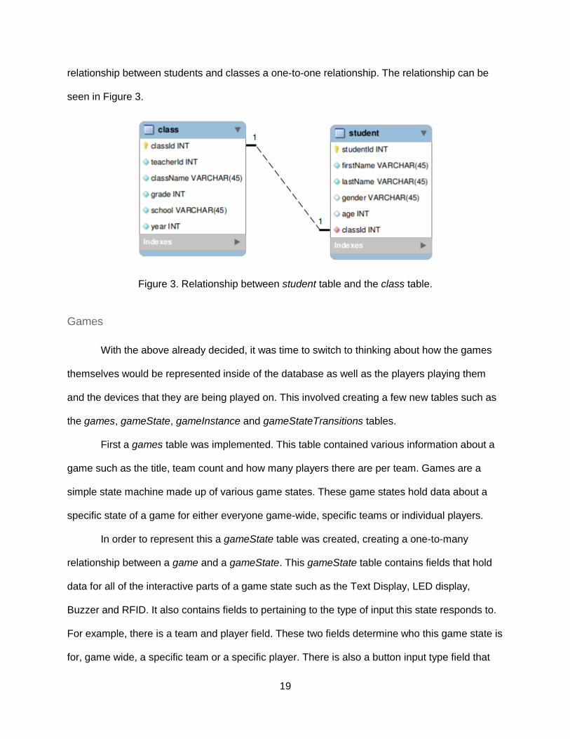
Once the class table was created it was possible to create a student table so that
classes could contain students. The student table was created with various fields such as their
name, gender, age and what class they belong to. While a student could be a part of many
classes, it was decided that each student can only belong to one class at a time. This made the
19
relationship between students and classes a one-to-one relationship. The relationship can be
seen in Figure 3.
Figure 3. Relationship between student table and the class table.
Games
With the above already decided, it was time to switch to thinking about how the games
themselves would be represented inside of the database as well as the players playing them
and the devices that they are being played on. This involved creating a few new tables such as
the games, gameState, gameInstance and gameStateTransitions tables.
First a games table was implemented. This table contained various information about a
game such as the title, team count and how many players there are per team. Games are a
simple state machine made up of various game states. These game states hold data about a
specific state of a game for either everyone game-wide, specific teams or individual players.
In order to represent this a gameState table was created, creating a one-to-many
relationship between a game and a gameState. This gameState table contains fields that hold
data for all of the interactive parts of a game state such as the Text Display, LED display,
Buzzer and RFID. It also contains fields to pertaining to the type of input this state responds to.
For example, there is a team and player field. These two fields determine who this game state is
for, game wide, a specific team or a specific player. There is also a button input type field that

20
describes what type of input is used on this state. This can either be a single button push or a
sequence of buttons. Lastly, this table contains information on the state count which used by the
server.
Since there are multiple ways to transitions between game states such as either a single
button press or a button sequence press, another table called gameStateTranistions was
created. This table held information on whether it is a single button press input and which color,
or a sequence button press and the sequence of colors as well as what gameStateId to
transition to if the input is correct. For example, if it is a single button press input type, a single
entry would be made for each color (in this case 4 entries) and the singlePush column would be
filled. If it is a sequence button press one entry would be made with the sequence of buttons in
the fourButtonPush columns.
Lastly, a table was needed to describe a running game. To accomplish this, the game
instance table was created. This table contains fields such as the gameId of the game this
instance is playing and the gameInstanceId. The frontend adds entries to this table to create
new game instances and the server automatically polls this table and adds any new games and
deletes any deleted games.
The relationship for all tables described can be viewed in Figure 4.

21
Figure 4. Relationship between games, gameInstance, gameState, hint and
gameStateTransitions tables.
Players
In order for active players to be represented in a game instance, a players table was
created. This table contained fields such as “gameInstanceId”, “studentId” and the current game
state that this player is on. When a device connects to the server, it adds a player to this table
with the appropriate data. When a device disconnects, the player is removed. Below the table is
shown in figure 5.

22
Figure 5. The players table that records active players in a game instance.
Devices
Next, it was necessary to implement a table to hold data about the different devices that
would be connected, as well as relationships between these devices and different games and
players. A device table was created with fields to hold data such as the IP address of the
device, the mac address, whether the device was connected, and also what player the device
belongs to. This creates a one-to-one relationship between a player and a device. Below this
table is shown in figure 6.
Figure 6. The devices table that records information about individual mobile devices that the
players carry with them.
23
Math Skills
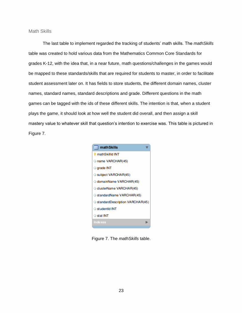
The last table to implement regarded the tracking of students’ math skills. The mathSkills
table was created to hold various data from the Mathematics Common Core Standards for
grades K-12, with the idea that, in a near future, math questions/challenges in the games would
be mapped to these standards/skills that are required for students to master, in order to facilitate
student assessment later on. It has fields to store students, the different domain names, cluster
names, standard names, standard descriptions and grade. Different questions in the math
games can be tagged with the ids of these different skills. The intention is that, when a student
plays the game, it should look at how well the student did overall, and then assign a skill
mastery value to whatever skill that question’s intention to exercise was. This table is pictured in
Figure 7.
Figure 7. The mathSkills table.

24
Frontend Rewrite
The goal of the front-end implementation is to create a teacher control panel that
teachers would be able to use to manage their classes, students, devices, games and game
instances. Teachers should be able to create an account for the control panel and then be able
to access it by logging into the control panel with credentials they created. The frontend should
allow the teacher to access and modify their own classes, their students and the devices that
belong to that teacher only. For this reason, it makes sense that the frontend should be hosted
remotely somewhere, and for multiple clients (teachers) at possibly different schools to access
this web service at the same time without having to host a server at each individual location.
The data also should be persistent and should remain stored in a remote location (database
server).
Software selection
I chose to implement the frontend as a web-based tool. In order to do this, I elected to
use the Tomcat 7 Web Server with Java Server Faces (JSF). This would allow me to write my
websites in xhtml (very similar to html) as well any code in java called from the xhtml. Many
hosting services support the Tomcat Web Server and it is as easy dragging one file (.war) to the
web server to deploy a website. Since JSF allows for the execution of java code, it would make
interacting with the MySQL database very easy, as I could use the JDBC library. To enhance
both the functionality and looks of the JSF framework, I decided to use an extension library
called Prime Faces (Prime Faces et al, 2016). This library adds more controls that a developer
can use in their website as well as gives access to different themes to make the overall look and
feel of a website better.

25
Overall Design Pattern
I chose to use the Model-View-Controller design pattern for the overall design of the web
server. This pattern is used to separate the entire application into three main distinct parts, the
model, view and controller parts (Tutorialspoint.com, 2016). The model part is used to
represent the object that carries the data, the view part is meant to represent the code that is
used to describe the User Interface and what the user sees; the controller part is used to act on
both the model and view and control the data flow whenever it changes. The controller and
model in my JSF project will be represented as java code in the wlfe.controller and wlfe.model
packages and the view will be represented as xhtml in WebContent/content/source directory.
Templates
The first part of the frontend was to design a template for the entire site. In order to do
this, the next design pattern that I used under the MVC design pattern was “templating”, which
is an integral part of JSF. Templating is a technique that implies the creation of a page that can
be used as base for other web pages, allowing the developer to reuse code and have a change
made in one spot affect many (Using Facelets Templates). I placed my templates in the
WebContent/content/source/templates folder.
I decided that I would break my website into three main parts, the header, content and
footer. This template is called the HeaderContentFooter template. I chose to do this as the
header and footer would remain exactly the same for every page and only the content would
ever change so there was no reason to recode the header and footer for every page. The
header contains a banner image and text while the footer contains some project and copyright
info.

26
Figure 8. The HeaderContentFooter template.
This type of template would be used on screens such as the login screen above in figure 8,
when there is nothing else to display other than the header, content and footer. Below is the
Login.xhtml including the HeaderContentFooter template.
The next template that I created was the HeaderMenuContentFooter template. This
template relied off of the header and footer portion of the HeaderContentFooter template but
defined its own content that also included a menu. This menu includes tabs to all of the main
pages of the teacher control panel. This type of template would be used when a teacher is
logged in and has access to the control panel and can navigate it. Below is the
VirtualDevice.xhtml including this template.
The last template that I created was the HeaderMenuTableContentFooter template. I
created this template because plenty of the content under the menu tabs such as classes,
devices, games, students had almost exactly the same layout, just some differences such as

27
titles, field names, etc. Below we can see ui:param being defined for the things that change
such as the titles and fields names.
For example, the tabs above all have a new, edit and delete button as well as a table. By
templating this all of this code could be reused instead of repeated in the pages that use this
template. Below is the Classes.xhtml using this template.
Teacher Login
The next part of the frontend implementation involved the design of a teacher login and
teacher account creation mechanism. This began by creating a new xhtml page called
Login.xhtml and having it use the HeaderContentFooter template. The login page required a
field for an email, password and login button as well as a link to sign up for an account. It also
required a dialog and the proper fields for that dialog. Below we can see images of the login and
signup in figures 9 and 10 respectively.

28
Figure 9. The Login Page.
Figure 10. The Signup Page.

29
Once the graphical part (view) of the login was complete it was time to write the
managed bean for this page. Each JSF page can be assigned a managed bean. This is
essentially a java class in which controls of the xhtml page can call functions or set / access
variables in the managed bean (Managed Beans). There are four different types of managed
beans, which include application, session, request, view and none. The ones that were
necessary for my application included view and session. The difference between view and
session is that view every time you refresh the page, a new instance of the managed bean for
that page is created meaning there is never any persistent data for the user. With session, as
long as the user has an http session with the server it's possible for there to be persistent data
on the page or that you may get returned a persistent managed bean. Since everything will only
be accessed when a teacher is logged in and has a http session (except for virtual device) all
beans are set as type sessions except for the virtual device bean which is of type view (you
don’t need to be a teacher or have an account to access the virtual device). The managed bean
java code is broken into two categories, the controller and the model. The model represents the
actual data for what we are doing, in this instance, the teacher is our model. The controller
contains all of the actions that need to happen based off of the input from the user. For
example, wlfe.controller.Login contains a method called validateUsernamePassword, which is
called when the login button is pressed. Below, the reader can see that the action of the
commandButton is login.validateUsernamePassword and also the validateUsernamePassword
method.

30
The same type of situation applies for the sign up. When the signup button is pressed, a popup
is opened, then when the create teacher button is pressed a signUp method in the managed
bean is invoked that creates the teacher. After validateUsernamePassword is called, the
validateMySQL method is called. This method returns true if the username and password and
valid in the database. Currently, no encryption methods are employed for the password yet.
If the validateMySQL method returns true, an HTTP session is created for the currently
connected client. An HTTP session is a way to keep identify a user across more than one page
visit (Using Sessions). Since most of the page visits that teachers will be doing require the user
to be logged in, this should be a good way keep track of a teacher object that will be set as an
attribute to the HTTP session. This way if the user attempts to navigate to a page without being
logged in, the server will see that the HTTP session returns a null object for the teacher attribute
and redirect to the login screen. Another reason the HTTP session can be useful is for selecting
data that belongs to individual teachers. For example, the classes page shows only classes for
the teacher that is currently logged in. By accessing the teacher attribute and returning the
teacher object, one can gain access to data such as teacherId, email, first name, last name,
school. This can be used in sql statements to select the data properly, usually by teacherId.

31
Classes, Devices and Students
The next portion of the frontend that was implemented was the main interface that
teachers would use to create, edit and delete classes, devices and students. These pages have
3 buttons at the top to create, edit and delete as well as a single selection data table below to
show the data and also to provide selection data for the edit and delete operations. Below in
figure 11 is what it looks like.
Figure 11. Main interface for teachers to create, edit and delete classes with students.
I determined that the interfaces for these three pages would be exactly the same. Only some
strings for headers or button titles would change as well as the data source for the data table
the page would contain. Because of this, I decided to create a new template, the
HeaderMenuTableContentFooter template, that these three pages could use. Doing this
significantly cut down on code density as well as created a nice way to easily replicate pages of
the same layout quickly and easily. I also decided that it would be best to design the managed

32
bean portion in a generic way. To do this the BaseHeaderMenuTableContentFooter.java base
class was created that all managed beans for pages that use the
HeaderMenuTableContentFooter template could extend. Since it's possible for the data model
to vary between classes that extend the BaseHeaderMenuTableContenFooter class, generics
were used in this class definition meaning when you create an instance of it, you also give it a
model type. An example of that would be ClassData model class.
The BaseHeaderMenuTableContentFooter class contains a list for all of the column names of
the data table you want, a map that links a string (column name in database) to a
DataTableColumn (field name in create / edit and its value), a list of all of the model objects in
the data table and the currently selected object. Since all classes that extend this class would
be using those class members, it was best to put them in a base class. This base class also
contains methods such as initData, createPressed, editPressed, editConfirmPressed and
deletePressed. Just from the name of these methods it's quite apparent when they are called.
initData is called when the page is first loaded, createProcess is called when the created button
in the create dialog is pressed. editPressed is called to open the edit dialog when the edit button
is pressed and editConfirmPressed is called when the confirm button in the edit is pressed.
Lastly, deletePressed is called when the yes button in the delete confirm dialog is pressed. The
base class provides you with a default editPressed and deletePressed that come built in and
working. While default methods are provided, it is possible to override the default method if
needed and define your own. The base class does not provide default methods for initData,
createPressed and editConfirmPressed. One must override these methods and write their own
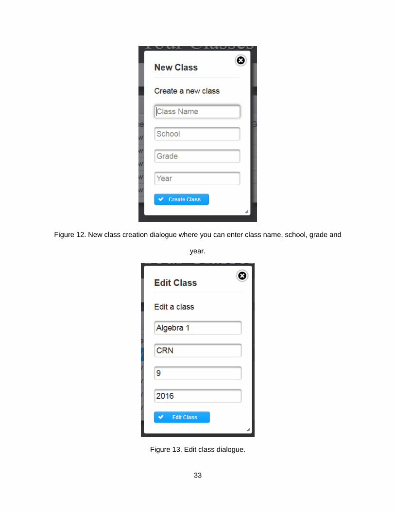
in the extended class. Below are a few images of the different dialogs.
33
Figure 12. New class creation dialogue where you can enter class name, school, grade and
year.
Figure 13. Edit class dialogue.

34
Edit class dialog shows values of currently selected row in the data table. Delete provides a
confirmation before doing the final delete.
Games
The next portion of the frontend was to implement an interface that teachers could use
for creating and managing games. This UI is very similar to the classes, devices and student’s
pages that use the HeaderMenuTableContentFooter template, but some aspects needed to be
modified. For example, I could not use the existing new and edit dialogs and would have to
create new ones from scratch. Due to this, I created a copy of HeaderMenuTableContentFooter
and renamed it HeaderMenuTableGameContetFooter, this way I could perform a more specific
and different implementation without having to modify or overwrite the other commonly use
template. As you can see below the overall layout is the same, where the only difference lies in
new and edit dialogs. The above is picture in figure 14.
Figure 14: Main Games Screen.

35
I decided to completely overhaul game creation from the previous ruby on rails version. I
used some of the layout ideas from the previous version but this time I decided the best
approach for game creation would be to use a wizard style game creation process. When the
user first hits, the new game button the game creation dialog appears, showing a wizard with
two steps, General Setup and Game States.
Figure 15. First step of game creation.
The first step is the general setup of the game. This included the title of the game as well as
how many teams this game has and how many players are on each team. After the user enters
this information, they can click the next button in the lower right hand corner and will be sent to
the second step, Game States.

36
The second step, Game State is a bit more complicated and is picture below.
Figure 16. Second step of game creation.
Since the entire wearable learning technology is based around a state machine controlling the
games, this is the interface you use to add and configure these states to your game. When you
first get into the setup the first state is automatically added for you. In the top left, you can see
the Add State button that is used to add another state to the game. The states are in an
accordion view meaning you can click on the title (State 1) to collapse the state and click on a
state already collapsed to reopen it. Inside of each accordion panel are two different main
areas, the Modify Outputs (left) area and the State Configuration Area (right).
The Modify Outputs area is used to change the value of the different output peripherals
for that state. It also has an accordion panel inside of it so you can configure all of the different
peripherals. These include Text (display LCD), LED (light), Buzzer (sound). Text is just raw
plaintext limited to one thousand characters and is filled out in a simple text box.

37
The next peripheral is the LED. Here you can set whether the LED should be on or off and what
color. You can use the color picker to help you pick the color.
Figure 17. LED color selection.
The final peripheral is the Buzzer. Here you can turn the buzzer on or off and decide how many
seconds the buzzer should stay on for if on is selected.
Figure 18. Buzzer on or off and duration selection.
The second area, the State Configuration area is used to select who the state is for and
whether the response to the state is a Single Push or Sequence Push response as well as the
states. The first field is the Respond To field. This a dropdown field. The options are as follows.

38
All games have a Game Wide option, which must be used for the first state of the game and is
an option used to configure a state to be sent to all teams of the entire game. When this option
is selected, you will configure which state each team of the game will go on upon what button or
sequence they push.
Figure 19. State configuration section, game wide addressing.
The next option in the Respond To Field is Team X, where X is the team number. If there are 2
teams, then in the dropdown list there will be Team 1 and Team 2. This option is used to send a
game state to a team and each player on the team will be individually configured to go to a
different state based upon what they press or the sequence they press.
Figure 20. State configuration section, team wide addressing.
The last option in the Respond To Field is --Player X, where X is the player number on
the team. This option is used when you want to send a state to an individual player. For
example, if each team has 2 players then under where the team is listed in the list, there will be
--Player 1 and --Player 2 in the list.

39
In the Player Respond To there is only one state configuration and that is for that player.
The game creator user can select which state to go to based upon a button press or sequence
press.
Figure 21. State configuration, single player addressing.
Once all of the states are configured, you can click the “create game” button in the lower right
hand corner. After that it will take a few seconds for the game to be saved into the database and
if it is successful a message will appear in the upper right hand corner of the screen indicating
“success”.
Game Instances
The next page in the frontend is the game instances page. This page is used to manage
which games are running on the sever. This includes creating new games instances as well as
ending currently running game instances. This page does not use any templates (other than the
HeaderMenuContentFoooter) as it is a one of a kind page.
40
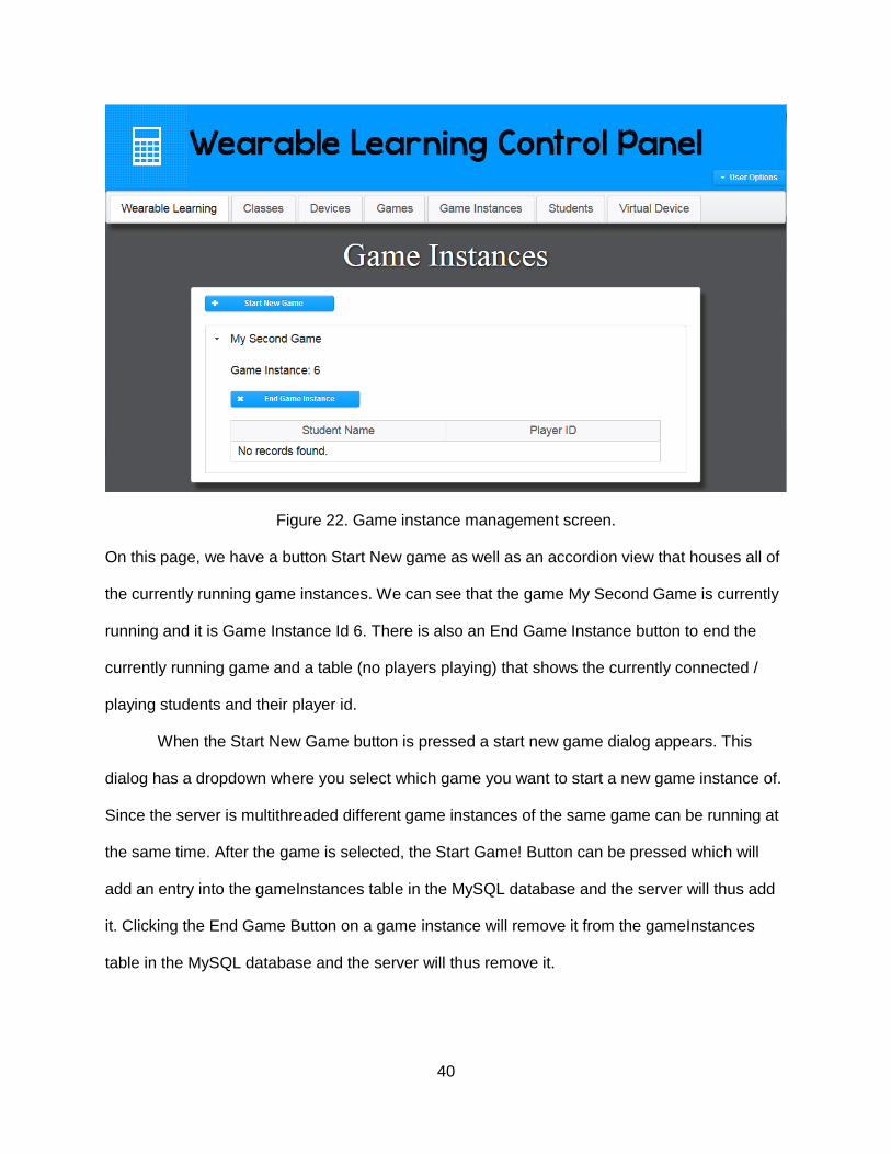
Figure 22. Game instance management screen.
On this page, we have a button Start New game as well as an accordion view that houses all of
the currently running game instances. We can see that the game My Second Game is currently
running and it is Game Instance Id 6. There is also an End Game Instance button to end the
currently running game and a table (no players playing) that shows the currently connected /
playing students and their player id.
When the Start New Game button is pressed a start new game dialog appears. This
dialog has a dropdown where you select which game you want to start a new game instance of.
Since the server is multithreaded different game instances of the same game can be running at
the same time. After the game is selected, the Start Game! Button can be pressed which will
add an entry into the gameInstances table in the MySQL database and the server will thus add
it. Clicking the End Game Button on a game instance will remove it from the gameInstances
table in the MySQL database and the server will thus remove it.

41
Figure 23. Select game to start dialogue.
Virtual Device
A virtual device page was implemented so that users could easily access a device via a
web browser and also so that I could have a web based device during development of the
server. This is also a one of a kind page and does not use any templates. When you first
navigate to the page you are presented with a wizard. This is used to configure the player for
the game. The first step of the wizard is to select you name from a list of student names that the
teacher manages. This is so that the game server can link a player to an actual student.
Figure 24. Virtual Device student login.
42
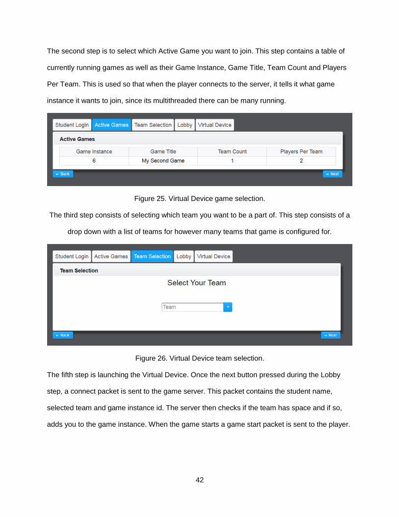
The second step is to select which Active Game you want to join. This step contains a table of
currently running games as well as their Game Instance, Game Title, Team Count and Players
Per Team. This is used so that when the player connects to the server, it tells it what game
instance it wants to join, since its multithreaded there can be many running.
Figure 25. Virtual Device game selection.
The third step consists of selecting which team you want to be a part of. This step consists of a
drop down with a list of teams for however many teams that game is configured for.
Figure 26. Virtual Device team selection.
The fifth step is launching the Virtual Device. Once the next button pressed during the Lobby
step, a connect packet is sent to the game server. This packet contains the student name,
selected team and game instance id. The server then checks if the team has space and if so,
adds you to the game instance. When the game starts a game start packet is sent to the player.

43
Figure 27. Virtual device itself.
After that the first game state is sent to the player as well.
Figure 28. Game welcome screen being displayed.
The student user can use the disconnect button to disconnect from the server. The student can
then use the back button to back and reconfigure anything and then keep clicking next until the
Virtual Device connects. If the browser accidentally closes, the user can reconnect by re-
entering the same credentials as before and it will resume functioning as usual. This is an
important and big feature for schools that don't have a very stable Wi-Fi: If a player disconnects
or loses connection, it is not a big problem, as they can just reconnect to the network, restart the

44
virtual device page, reconfigure exactly how they did before and pick up exactly where they left
off. The virtual device also contains four buttons, 1-4, red, green, blue and black respectively.
When any of them are pressed, a button packet is sent to the server to the handle the press and
transition states accordingly.
Backend Rewrite
Software Selection
The biggest drawback of the older Ruby on Rails server was the lack of Ruby Version
Managers for platforms other than Linux, such as windows. In order to keep the server as cross
platform as possible, I decided it was best to write the server as a java application. Java runs on
all of the major platforms so schools and teachers can run it on whatever system their school
runs on. The server is a modular design and uses asynchronous sockets for communication
over the internet. The server is multithreaded allowing for multiple game instances to all run
simultaneously. The server is able to be setup so that it can run in a remote location on a
remote server and schools and teachers can access it that way or the server could be run
locally.

45
Modules
The server is of modular design. This means that all of components of the server are
broken into different modules and there is central singleton module manager that handles all of
the loaded modules. All modules created for the server must extend the Module class which
implements the IModule interface. Below is a class diagram of the of the Module class and
interface.
Figure 29. Module UML diagram.
Looking at the interface we can see that anything that implements IModule (Module) must
defined setup, cleanup and update method. These methods are used called by the module
manager. Setup is called when a new instance of a module is created, while cleanup is called
when the module is being removed from the list of running modules. Lastly, update is called in a
for loop in an update method (in the module manager) that loops through all of the currently
running modules and calls their update function.
The ModuleManager class is a singleton class that is initialized when the server first
starts up. Due to the fact that the ModuleManager is of singleton design, it’s possible to get an

46
instance of the ModuleManager anywhere inside of the program. A class diagram of the
ModuleManager is shown below.
Figure 30. Module Manager UML diagram.
We can see that the ModuleManager contains methods to add and remove modules from its list
of modules as well as a method to update all modules. It also contains an enumeration of
modules. This enumeration is used by the getModule method in the ModuleManager class. By
passing this method a member from the Modules enumeration, it will loop through all of the
modules and check to see if there is a module of that that type and if so return it.

47
Logger Module
The logger module is the first module that is added to the module manager. This is so
that logging can begin immediately and any other modules will be able to log data when they
start up. The logger modules operation is very simple. When the modules setup method is
called, a new log file is created (wlbelog.log) in the same directory as the server executable.
When you want to write a new line to the log file, you simply call the write method and give it a
string to log. Below is a class diagram of the Logger module.
Figure 31. Logger Module UML diagram.

48
Server Module
The server module is the main module and is responsible for the receiving data and
broadcasting it out to the rest of the modules and tasks as well as transmitting data. When the
server module is first added, setupServerSettings, setupServerTime and setupServerSocket are
called. Server settings setup up the settings module which server time setups up a clock to keep
track of time since the server has started. The method we are concerned with is
setupServerSocket. This method creates a new AsynchronousServerSocketChannel that listens
on port 3333. Since the server is asynchronous is will never block waiting for connections or
sending and receiving data. Inside of this method, AcceptIncomingConnections is called which
begins listening for clients to connect. When a client does connect, a ServerConnectHandler is
called which creates a new instance of clientData and populates this. It then puts the client into
read mode. When data is received from this client, a ServerRequestReadWriteHandler is called.
The data is read and then broadcasted out to all modules and tasks (in form of a packet, which
is described later) who will decide whether or not to respond to that data. The ClientData class,
holds client specific information such as the client socket as well as the client's buffer for reading
and writing. When the server wants to write to a client, it calls the write method write which
takes the clients ClientData as well as the packet that is to be sent. Operation of the server will
be described in more detail in the server operation section. Below is a class diagram of the
server module and the client data class.

49
Figure 32. Server Module UML diagram.
50
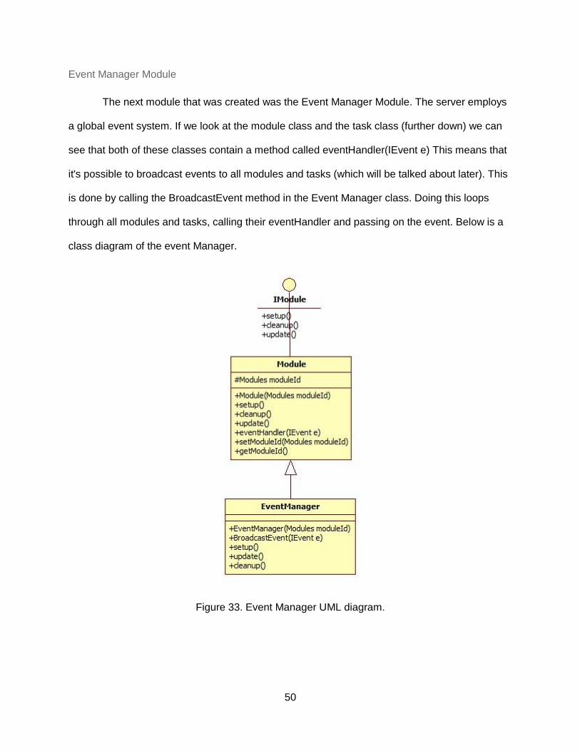
Event Manager Module
The next module that was created was the Event Manager Module. The server employs
a global event system. If we look at the module class and the task class (further down) we can
see that both of these classes contain a method called eventHandler(IEvent e) This means that
it's possible to broadcast events to all modules and tasks (which will be talked about later). This
is done by calling the BroadcastEvent method in the Event Manager class. Doing this loops
through all modules and tasks, calling their eventHandler and passing on the event. Below is a
class diagram of the event Manager.
Figure 33. Event Manager UML diagram.

51
Settings Module
The settings module was created to hold instance specific settings as well as any other
configuration. It is not fully implemented and right now only used to hold database settings.
Task Manager Module
The last module that was created was the task manager module. The job of this module
is manage all tasks (discussed later on) that are currently running on the server. A task is simply
a thread with its own operation running. The task manager provides methods to add and
remove these tasks. Below is a class diagram.
Figure 34. Task Manager UML diagram.

52
Server Packets
Due to the fact that Java sockets require you to send and receive raw bytes, a packet
system was created to more easily handle the data being sent to clients as well as the data
being received from clients. This means that whenever the server sends data to a client, it
creates a packet and then this is written to the server module and eventually disassembled from
a packet into a byte buffer to be sent across the network. A similar thing happens when data is
received. The data is parsed and assembled into a packet and then broadcasted to the entire
server application. Packets also have a packetType (enumeration) this is used to identify the
packets type when receiving data as well as sending. Below is a class diagram of the packet
system.
Figure 35. Server Packet UML diagram.

53
Connect Packet
The connect packet is used when a client wants to connect to the server. The client
sends a connect packet. It is then processed by the server and then a response is sent back to
the client. The connect packet contains critical information such as the student's name, team
and the game instance id that is used to make sure the player is connected to the correct game
instance and assigned to the correct team. Below is the class diagram of the connect packet.
Figure 36. Connect Packet UML diagram.

54
Disconnect Packet
The disconnect packet is the opposite of the connect packet. When a client wants to
disconnect from the serve they send a disconnect packet. This packet contains the game
instance id that the student is currently playing in as well as the student's name. This
information is used to remove the student from the game. No confirm packet is sent back, the
connection is simply closed. Below is the class diagram of the disconnect packet.
Figure 37. Disconnect Packet.

55
JSON Packet
The last packet is a JSON (Javascript Object Notation) Packet. This packet simply
carries a IJSONPacket which is another subset of JSON specific packets (which will be
described below). These packets contain strings formed from a java object. I chose to use
JSON as the main method of communication for the server and the device because it is very
easy to serialize class data into string, send it across the network and then deserialized this
data back into an object. Below is the class diagram of the JSON Packet.
Figure 38. JSON Packet UML diagram.

56
Shared JSON Packets
As stated in the description of the server JSON packet above, these packets contain
another packet that is a level below the server packets. The shared JSON packets are located
in a separate project that is shared between both the frontend and backend. This is so the
frontend and backend can use the same JSON packets to communicate back and forth with
each other. These packets are similar to the server packets in layout. Below is a class diagram
of the shared JSON packets.
Figure 39. Shared JSON Packet UML diagram.
57
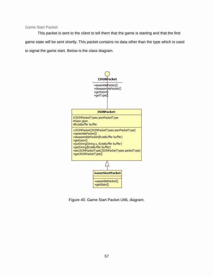
Game Start Packet
This packet is sent to the client to tell them that the game is starting and that the first
game state will be sent shortly. This packet contains no data other than the type which is used
to signal the game start. Below is the class diagram.
Figure 40. Game Start Packet UML diagram.

58
Button Packet
A button packet is used when the there is a button press on the client device. This
packet contains the ButtonData class which holds the playerId who pressed the button as well
as the button number 1-4 (red, green, blue, black).
Figure 41. Button Packet UML diagram.

59
Display Packet
A display packet is used when the server wants to update the client's display screen. A
display packet contains a DisplayData which contains the text to display on the screen. Below is
a class diagram.
Figure 42. Display Packet UML diagram.
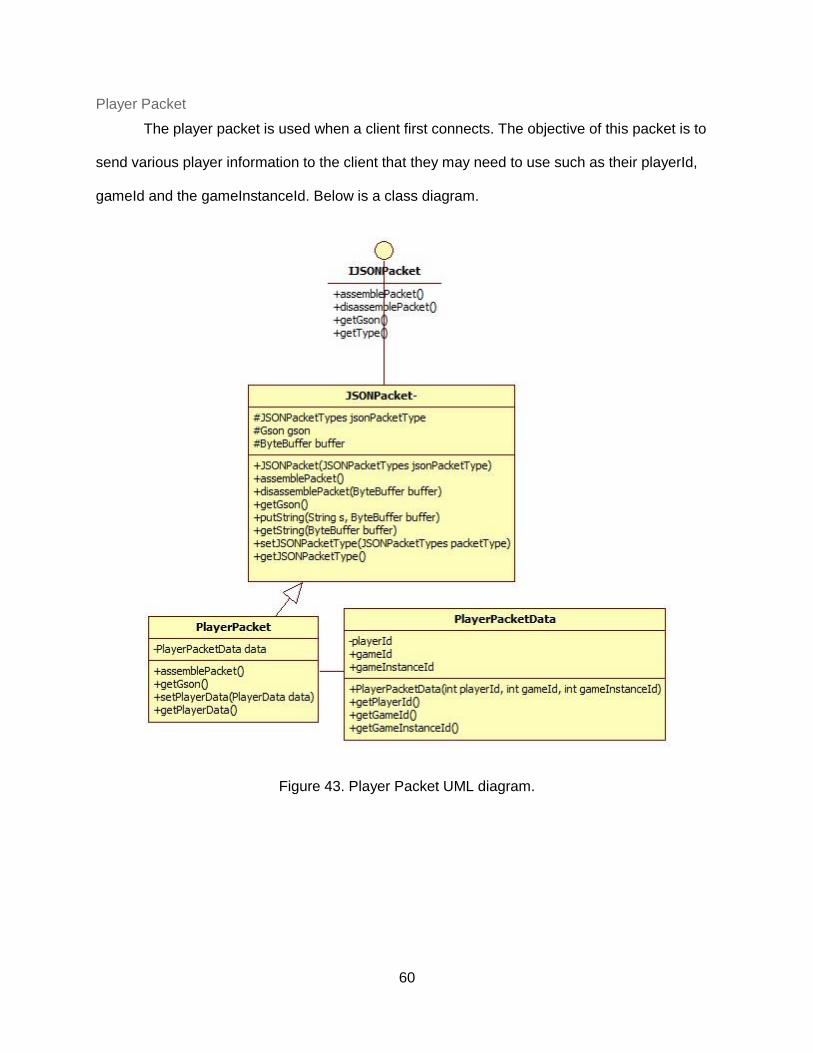
60
Player Packet
The player packet is used when a client first connects. The objective of this packet is to
send various player information to the client that they may need to use such as their playerId,
gameId and the gameInstanceId. Below is a class diagram.
Figure 43. Player Packet UML diagram.

61
Game State Packet
A game state packet is used to send an entire gamestate to the client. This could
include, display data, led data, buzzer data, rfid data, etc. Right now, only display data is
implemented. A class diagram is below.
Figure 44. Game State Packet UML diagram.

62
Events
Built into the server is an event system. This system is designed so that events can be
broadcasted to all modules and tasks if needed. This system also allows for other events to be
created and used such as timers. For example, if the server needs to do a task every five
seconds, it's possible to setup a timer that triggers an event every five seconds to the task or
module that needs this. The event system currently implemented is very basic. The event
interface has no methods and the event class only has one attribute, the eventType which is the
type from the Event Types enumeration. The only event right now is a packet received event.
Below is a class diagram of events.
Figure 44. Event UML Diagram.

63
Packet Received
The only type of event implemented right now is packet received event. Whenever the
server receives data from a client, the data is assembled into a packet and then broadcasted
using the broadcastEvent function in the event module to all tasks and modules. It is up to the
module or task or filter out these events and only respond or take action to the packets that are
for that module or task. For example, if a game instance receives a PacketRecieved event, it is
its job to then dissect this packet and look at various information such as gameInstanceId and
decide whether or not this packet is destined for this game instance. This is needed because
the server is multithreaded and there may be multiple game instances running at the same time.
Figure 46. Packet Received Event UML diagram.

64
Tasks
The old version of the server was only single threaded. This meant that only one game
instance could be run at a time. The new version of the server has taken a different approach
and includes multithreading. This means that multiple game instances of the same or different
game can be played at the same time. In order to accomplish, tasks were created. A task is
simply a different thread operation in parallel with the main thread. Tasks can be used to
created multiple game instances but also to run other functions such as daemons in parallel with
the main thread. This means that the only job of the main thread is to receive data and route
that data appropriately to the correct module or task. A task differs from a thread in only one
aspect, modules are run in the main thread. Below is a class diagram of the task system.
Figure 46. Task UML diagram.
65
Game Instance
The game instance task is the core “game engine” of the server. This task is responsible
for running the game as well as handling all interactions clients make with their devices. When a
game instance is first started, it must be given a gameInstanceId as well as a gameId when the
task is first created. This is so the game instance task can respond to packets directed towards
its gameInstanceId as well as know what game it is playing, respectively. After that it gets an
instance of the logging module and MySQLDaemon module from the module manager for use
within the game engine. One the initialization is done; the engine sits idle until it receives and
event in its event handler method. Once it does, a conditional branch will have decided which
type of event it is and branch to the proper code. Right now, the only event implemented into the
game engine is a packet received event. This event is triggered anytime the server receives
data from a client. After that, the packet received is pulled out of packet received event. There
can be one of three cases, the packet is a PLAYER_CONNECT packet, a
PLAYER_DISCONNECT packet or a JSON_PACKET packet. When a player connects, the
playerConnect method is called. This method verifies the packet is for this game instance,
checks to see if the player is reconnecting (due to a lost connection) or if not, creates a new
player and adds it to the list of current players. Next the setupNewPlayer method is called which
inserts the player into the player's table in the database. After that, three other methods are
called, sendPlayerData, which sends the playerId, gameId and gameInstanceId back to the
player's client. Next the sendGameStart method is called which simply sends a GAME_START
JSON packet telling the client the game is starting and except the first game state to arrive
shortly. Lastly, the sendGameState method is called, which sends the first game state to the
player. When a disconnect packet is received, the player is removed from the game instance as
well as the players table in the database. The last possible packet case is a JSON_PACKET. If
this is the case, the handleJSONPacket method is called. Based off of the type of JSON packet
it is (display, button, etc.) the code will branch appropriately. Right now, the only JSON packet

66
that the game instance responds to is a button press. When this happens, the
handleButtonPress method is called. This method loops through all of the current players and
looks for the one with the playerId that the packet was sent from. After that
setNextGameStateForPlayer is called which will select the next game state from the
gameInstanceTransitions database table based off of the button pressed. After that the
sendGameState method is called which pulls out the state information from the gameState table
such as the new text to display, led color, buzzer, etc. This is then send to the client in the form
of a GameStatePacket. Below is a class diagram of the game instance class.

67
Figure 48. Game Instance UML diagram.

68
Game Instance Daemon
The purpose of the game instance daemon is very simple, to poll the gameInstance
table for new game instances as well as game instances that may no longer be there and must
be ended on the server. When the GameInstanceDaemon is first started, the players table is
truncated so that it can be reused on this new server instance. After that the mysqlPoll function
is called every 10 seconds, which checks the gameInstance table for new instances and adds
them to the game server or checks to see if an instance has been removed and removes it from
the server. Below is a class diagram of the game instance daemon class.
Figure 49. Game Instance Daemon UML diagram.

69
IO Daemon
The point of the IO Daemon task is handle multiple threads trying to write data to the
server. Since the actual server (sockets portion) is only single threaded and there could be
potentially other tasks trying to write all simultaneously, I needed to come up with a queue type
solution where tasks and modules can write to the IO Daemon queue which the IO Daemon will
process as fast as it can. Below is its class diagram.
Figure 50. IO Daemon UML diagram.

70
MySQL Daemon
The point of the MySQL Daemon is to provide one single database connection to the
entire server (all modules and tasks). This way the server isn't constantly opening and closing
connection or has a large amount of connections open at the same time. When this task first
starts up, it establishes a connection with the database and whenever something needs to
access the database, it gets an instance of the daemon from the task manager and uses the
getConnection method which returns a MySQL connection that can be used to perform queries.
Below is the class diagram.
Figure 51. MySQLDaemon UML diagram.

71
Android Virtual Device App
The creation of an android virtual device app was not part of the original plan. When
looking for devices for the study for students to use to play the game “Estimate It” on my
system, I came upon a lot of sixteen Motorola Droid 2 phones. They all included batteries and
most were in working condition. Upon receiving the devices, I factory reset one and got it
connected to the WPI wireless network. After that navigating to the front end virtual device, the
page didn't load correctly. I learned that the devices had an older version of Android, 2.3 to be
specific and didn’t support the chrome browser. Therefore, the JSF frontend was incompatible.
With the study in a few weeks, I needed to design an android app instead since I was already
stuck with the sixteen Motorola Droid 2 phones. The android app is broken up into two main
activities the configuration activity and the virtual device activity.
First Activity
The purpose of the first activity is to allow the user to configure which game they want to
connect to. This activity allows the users to find their username in a list, select their game and
select the team they want to be a part of for the game. The app uses the mysql connector to
populate the dropdown data. There is also a checkbox option to select a backup server as well
as a refresh button to either connect to the backup server or refresh the dropdown data for the
regular server. Once the user has selected their information properly they can hit the connect
button to try and connect to the game server.

72
Figure 52. Android Virtual Device Student Login.

73
Second Activity
The second is the virtual device itself. This is what students interact with when playing
the game. It has a display screen, four colored buttons (red, green, blue, black) and a
disconnect button. This activity uses sockets in order to connect to the backend game server. It
uses the exact same method and most of the same code as the frontend virtual device. This
includes the code for connecting to the backend server, receiving player and game data, and
sending button presses. It accomplishes this by using the shared library that the frontend and
backend java project use. Since you can use java to program apps, this makes it very easy to
reuse code from the frontend in my app, allowing for quicker development.
Figure 53. Android Virtual Device Main Screen.

74
Study
Results to the Game Play Survey
Out of the 54 students that participated in the study, 42 answered the survey after
playing the game. The first question that was asked was “how difficult was the game to play?”
This question was on a scale from 1 - 4 where 1 was not difficult and 4 was difficult. Looking at
the results, 79% of the people rated the difficulty as 1 and 21% as a difficulty of 2. Considering
the game is meant to be played by 4th graders and was being played by 11th graders, the
results make sense. The 9 people that rated it as difficulty 2 most likely chose that because of
the server difficulties experienced on day one.
Figure 54. How difficult was game to play survey question.

75
The second question that was asked was “how entertaining would a 4th grader find the
game?” This questions used the same 1-4 scale as the question above. The results for this
question were a bit more spread out than the previous question, however ⅔ of the people still
found the game entertaining. Again, I believe this is because of the server difficulties
experienced by some sessions on the first day.
Figure 55. How entertaining to a fourth grader survey question.
The third question asked the students if they had any issues with system stability such
as freezing, crashing, etc. There were 36 short text responses to this question. Below is a
sample of the responses. Most of the responses were about the app freezing and the phones
not working well. This was most likely due to having to use the backup server on the first day.
There are some no’s, which are responses from the second day when everything worked
perfectly.

76
Figure 56. Issues students had with system.
The fourth question was asked to see if students found the directions easy to
understand. The results of this question are quite straightforward as everything answer yes.
Figure 57. Survey question pertaining directions.

77
The fifth question involved hints. Whenever a question is asked to the student they are
given an option to press the black button to receive a hint on that question if they are stuck.
Below we can see that only 21% of the people found the hints helpful and 79% didn’t. This is
most likely due to the fact that not many of students said they used the hints when we asked
them in class if they did. Also, due to the fact that this game is made for 4th graders and not
11th graders, the players may not have found them useful as it may have been information they
already know.
Figure 58. Survey question about hints.
The sixth question was a follow-up to the fifth question. 75% of the students said the
hints would be helpful and 25% said they wouldn't be helpful to fourth graders. This backs up
the fact that because 11th graders are playing a game for 4th graders they didn't find the hints
helpful because they are already knew the information presented in the hint and since they
already knew the info they could make a good assumption to whether 4th graders would find the
hints helpful.

78
Figure 59. Survey question about hints continued.

79
Results to the Game Design Survey
At the end of the third day, after students were done redesigning their game to be more
state based and more similar to “Estimate It,” they were given a link to complete one last survey.
This was the game design survey and asked questions dealing with how their redesign went.
The first few questions were given just to figure out what day the person filling out the survey
played the “Estimate It” game. The next few questions ask things such as how difficult was it to
design a math game, how similar was your game to estimate, etc. Below is the survey given to
the students. Out of the 54 students that participated in the study, 31 answered the survey.
The first question that was asked was how difficult was it for you to design a math game
given a set of constraints. This question was asked on a scale from 1-4 with 1 being easy and 4
being hard. Looking at the results, 87.1% of the people that participated in the survey found the
task of designing a math game easy. Only a very small portion of the students (12.9%) found it
slightly difficult or very difficult. Most likely the people who found it hard, found the constraints
too tight or didn't fully understand them.
Figure 60. Survey question about design difficulty.

80
The second question was asked to get an idea of how similar the students games were
on the first or second day that they created them to “Estimate It.” It uses a 1-4 scale with 1 being
not very and 4 being very. Looking at the results, almost every person (93.6%) found their game
wasn't similar in terms of design and playability as “Estimate It,” meaning most of them probably
didn't take a state or flow based approach. We can see that there are a few outliers, 6.4% of the
people. These outliers are mostly due to the fact that maybe the students game was designed
with a pattern the same as the one of “Estimate It!’
Figure 61. Survey question about game similarity.
The third question was asked to find out how similar the game they designed the first or
second day was to “Estimate It” by the end of the third day, after redesigning their game.
Looking at the results a large majority (83.9%) found it difficult to redesign their game by the end
of the third day. This is probably because most of the games didn't take a state based approach
in the beginning anyways, so it may have been hard to redesign it to a state based approach.

81
Figure 62. Survey question about similarity of games.
The fourth question involved asking the students how hard it was to determine the underlying
state based design pattern for “Estimate It!”. Looking at the results, a majority of students
(87.1%) found it pretty easy to determine the underlying state based design of “Estimate It!” It's
possible the other 12.9% were never introduced to any state based concepts and hence why
they may have found it more difficult.
Figure 63. Survey question about games underlying state base design.

82
The fifth and sixth question involve asking the student about his or her knowledge of state
machines, more specifically how much did you know about them before this study and how
much do you think you know now. Most students (83.9%) said they didn't know anything about
state machines before the study. Most students (77.4%) then said that they feel like they know
more and are more comfortable with state machines after the study. There are a few outliers in
both and these are most likely people who had prior knowledge of state machines, which a few
said they did in class.
Figure 64. Survey question about state machines.
Figure 65. Survey question about state machines.
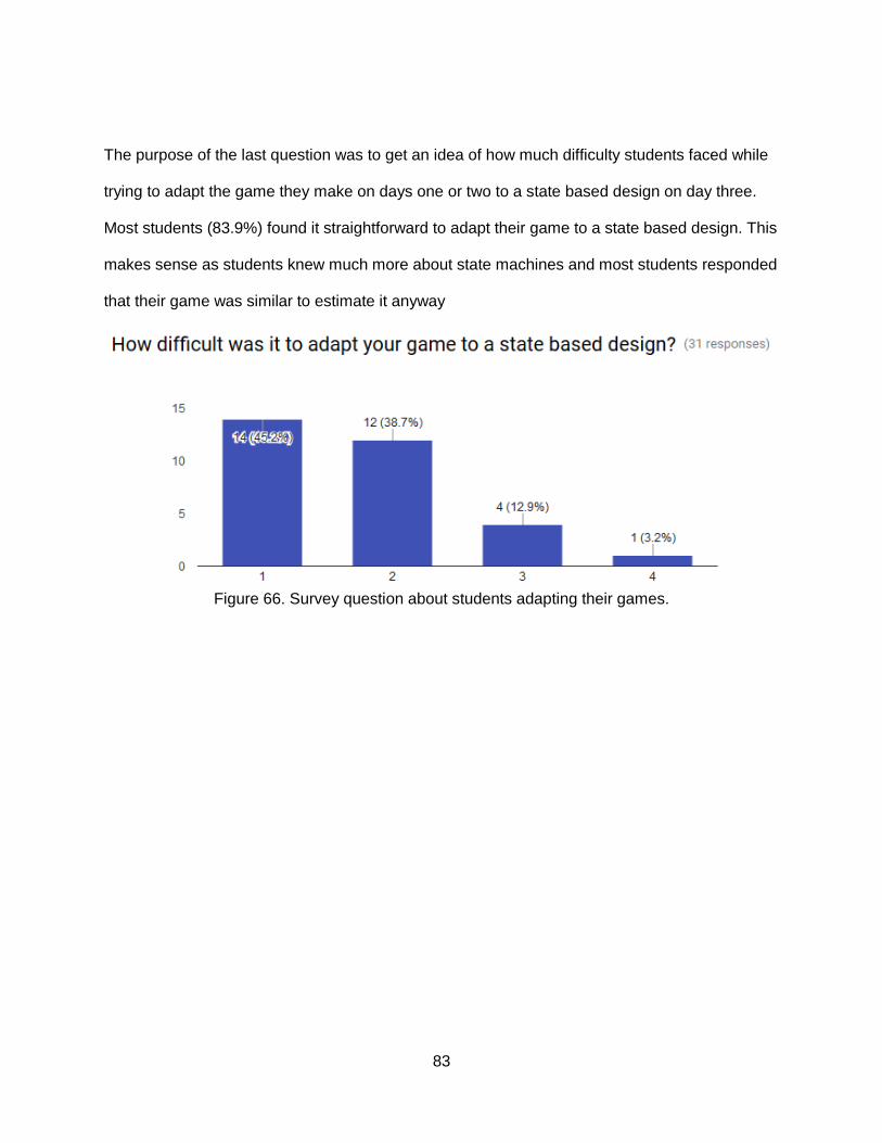
83
The purpose of the last question was to get an idea of how much difficulty students faced while
trying to adapt the game they make on days one or two to a state based design on day three.
Most students (83.9%) found it straightforward to adapt their game to a state based design. This
makes sense as students knew much more about state machines and most students responded
that their game was similar to estimate it anyway
Figure 66. Survey question about students adapting their games.

84
Discussion
Overall the project went pretty smoothly. Then plan was to develop the database in A
term, the frontend and backend server in B term and then leave C term for testing with students.
This schedule ended up working out perfectly and gave ample time to get all of the required
tasks done. After reviewing the results for all three categories, it is apparent that they have been
completed to specification as described in the methodology. Being able to test with students
live, especially at a different school really allowed me to put the system I designed to the test.
By being able to test with 54 students (6 groups of 9 each) I was able to track down some very
important issues, such as issues with server outages. Fortunately, I was prepared though by
incorporating a backup option, but unfortunately that only half way worked. This was a very
good learning experience.
The part that I found most interesting out of the project was the study itself. It was very
striking to see students playing games on a system I designed and having a fun time. It was
also very interesting seeing the different types of games that students would design during the
study. The types of games ranged so widely, it was interesting hearing the students talk about
their games, how they worked and seeing the thought process behind it. Some of the games
were even possibly to implement very easily into the game engine.

85
Conclusions
Going back to my research questions, I consider I have managed to answer the
questions I initially posed. The questions and answers to these questions are posted below:
1. Is it possible to recreate the proof of concept from the IQP as a stable web-based
technology to support the play of multiplayer games?
a. Yes, it is possible to recreate the proof of concept from the IQP as a stable web-
based technology. This was proven on the second day of the study when the
game system was fully working. Three classes of 9 students each were all able
to play the game, one after another without any issues.
2. Do these multiplayer games workout in reality and can it be reliability ran with a
full class of students?
a. Yes, these games workout in reality based off of the results of the study and can
be ran with a mostly full class of students. While games are only nine players and
there may be more students per class than that, it is possible to start multiple
instances of the game and have different games running at the same time.
3. Is it possible for students to understand the idea of creating state based math
games for the system that I designed?
a. Yes, this is possible. Most students in the beginning have no idea about what a
state machine was. By the end of the study every person answered that they
knew what they were and were more familiar with them. They also redesigned
their game to be more like “Estimate It” so it could be run on my system. Many
students were able successfully redesign their game to be more state
approached.
4. What is the best way to design these state based games on the computer?

86
a. When designing the frontend teacher control panel, one of the big design
decision was how to setup the game editor for teachers to use. At first, I used a
very basic editor where teachers would basically use a UI to fill out database
entries. Later it was decided the best type of editor would be one that mimicked a
state diagram. This would allow users to easily visually edit the game. There
however was not enough time to implement this method.
5. Would teachers find this system as a valuable teaching tools?
a. Yes, teachers would find this system as a valuable teaching but, but for
classrooms of the younger age or ones that are the correct age for the game.
“Estimate It” is made for fourth graders, but we were testing with eleventh
graders, making the system not very valuable to the teacher we were testing
with.

87
References
Casano, J., Tee, H., Agapito, J., & Arroyo, I. (n.d.). Migration and Evaluation of a Framework for
Developing Embodied Cognition Learning Games. Retrieved September 14, 2016.
Cerruti, C., Leondires, P., McCarthy, D., Ramadan, S., Silva, A., & Tapply, D. (2015). Physical
Games for Learning. Retrieved from https://web.wpi.edu/Pubs/E-project/Available/E-
project-100915-160926/unrestricted/Physical_Games_For_Learning.pdf
Jendrock, E., Cervera-Navarro, R., Evans, I., Gollapudi, D., Haase, K., Markito, W., Srivathsa, C.
(2013) Managed Beans in JavaServer Faces Technology - The Java EE 6 Tutorial.
Oracle and its affiliates.
Prime Faces. n.d. Retrieved September 1, 2016 from http://www.primefaces.org
Rai, D. (2016). Modes and Mechanisms of Game-like Interventions in Intelligent Tutoring
Systems (Unpublished master's thesis). Worcester Polytechnic Institute.
Table Relationships. (n.d.). Retrieved October 1, 2016, from
http://www.databaseprimer.com/pages/table-relationships/
Tutorialspoint.com. "Design Patterns MVC Pattern." Www.tutorialspoint.com. N.p., n.d. Web. 1
Oct. 2016.
Oracle (2016) "Using Facelets Templates - The Java EE 6 Tutorial." Using Facelets Templates -
The Java EE.
6 Tutorial. N.p., n.d. Web. 1 Oct. 2016.
"Using Sessions and Session Persistence in Web Applications." Using Sessions and Session
Persistence in Web Applications. N.p., n.d. Web. 1 Oct. 2016.
Wilson, R. A. (2011). Embodied Cognition. Retrieved September 14, 2016, from

88
Appendix
Appendix A: Game Play Survey

89

90

91
Appendix B: Game Design Survey

92

93