physical chemistry chemical physicspolysurf.mse.gatech.edu/wp-content/uploads/2010/11/... ·...
TRANSCRIPT

www.rsc.org/pccp Volume 10 | Number 28 | 28 July 2008 | Pages 4069–4200
ISSN 1463-9076
Physical Chemistry Chemical Physics
COMMUNICATIONNovoa et al.[Cyanil]22– dimers possess long, two-electron ten-center (2e–/10c) multicenter bonding
COVER ARTICLETsukruk et al.Mechanical properties of composite polymer microstructures fabricated by interference lithography

Mechanical properties of composite polymer microstructures fabricated
by interference lithography
Srikanth Singamaneni,ab Sehoon Chang,ab Ji-Hyun Jang,c Whitney Davis,a
Edwin L. Thomas*cand Vladimir V. Tsukruk*
ab
Received 21st December 2007, Accepted 17th April 2008
First published as an Advance Article on the web 27th May 2008
DOI: 10.1039/b719709h
We demonstrate that organized, porous, polymer microstructures with continuous open
nanoscale pores and a sub-micron spacing obtained via interference lithography can be
successfully utilized in a non-traditional field of ordered polymer microcomposites.
The examples presented here include porous matrices for the fabrication of binary,
glassy-rubbery microcomposites with intriguing mechanical properties with large energy
dissipation and lattice-controlled fracturing.
1. Introduction
Modern applications involving microfabricated structures and
microdevices based upon polymeric materials call for sophis-
ticated engineered surfaces and interfaces tailored to control
elasticity, plasticity, adhesion, friction, chemical, and thermal
properties. Specific examples of such applications include
components for integrated photonic circuits, separation and
chemical filtration, biological tissue scaffolding, biointerfaces
and biosensors, environmental monitoring, microfluidic cir-
cuits, and MEMS-based sensors and actuators.1–11 Various
sophisticated MEMS-based microdevices have already been
fabricated from polymeric materials.12 These include micro-
gears, microcoils and pumps,13,14 microvalves and grippers,15
microchannels and high-aspect ratio beams,16–18 haircells,19
microcantilevers, and tribological coatings.20,21 A common
approach for the fabrication of polymeric MEMS devices is
the application of photolithographic techniques using epoxy-
based reactive materials such as SU8, a common negative
photoresist.12 On the other hand, soft lithography encom-
passes other approaches, including microcontact printing,
capillary transfer lithography, imprint lithography, and edge
lithography, to name a few.22–24
Polymer/air (porous) structures, in which both phases are
bi-continuous in three dimensions, exhibit large specific sur-
face areas in conjunction with the controlled hierarchical
porous network. This combination provides a unique platform
for designing microstructured materials with interesting trans-
port and adsorption properties. In addition to the steric effects
imposed by the porous structure, chemical modification of the
porous materials enables tailoring of the surface chemistry and
polarity, which provides additional functionality. Porous ma-
terials find numerous applications in the field of life sciences,
such as cell culture substrates for cell adhesion, biomaterials as
tissue engineering scaffolds with biocompatible and biode-
gradable properties, cell patterning, and protein microar-
rays.25,26
Dissipation and absorption of mechanical energy within
highly porous microcomposite structures is another intriguing
topic critical for some MEMS applications where high me-
chanical loads are involved. However, most of materials
Srikanth Singamaneni is
currently pursuing his PhD
in Polymer Materials
Science and Engineering at
Georgia Institute of Tech-
nology. He has co-authored
30 refereed articles in archi-
val journals and made
presentations at national
conferences. His current
scientific interests include
the fabrication of organic
and inorganic nanostruc-
tured materials for ad-
vanced physical and chemical sensors, and interaction of
electromagnetic radiation with metal nanostructures.
Vladimir V. Tsukruk holds a
joint appointment as a Profes-
sor at the School of Materials
Science and Engineering and
School of Polymer, Fiber, and
Textile Engineering, Georgia
Institute of Technology. He
has co-authored 250+ articles,
19 reviews, one book, co-edited
three volumes, and holds four
patents. His research activities
are in the fields of surfaces/
interfaces, molecular assembly,
nano- and bioinspired materi-
als. He serves on the editorial advisory boards of Polymer and
Curr. Chem. Biology.
a School of Materials Science and Engineering, Georgia Institute ofTechnology, Atlanta, GA, USA. E-mail: [email protected]
b School of Polymer, Textile and Fiber Engineering, Georgia Instituteof Technology, Atlanta, GA, USA
cDepartment of Materials Science and Engineering, MassachusettsInstitute of Technology, Cambridge, MA, USA. E-mail: [email protected]
This journal is �c the Owner Societies 2008 Phys. Chem. Chem. Phys., 2008, 10, 4093–4105 | 4093
PERSPECTIVE www.rsc.org/pccp | Physical Chemistry Chemical Physics

suggested and discussed to date for such applications are either
microscopic foams with random combination of open/close
porous interior or macroscopic organized structures (such as
civil engineering truss frames). Only a few examples of micro-
scopic organized porous structures have been reported to date.
Although foam-like structures can be exploited for lightweight
designs with microscopic porous morphology, they exhibit
much lower strengths and their high ‘‘polydispersity’’ leads
to variation in the local physical properties on a microscopic
scale.27
Trusses are well known, highly organized 2D and 3D light-
weight structural constructions composed of struts (beams)
and nodes (joints) with excellent mechanical properties. They
are widely used in civil engineering but rarely considered as
examples for polymer microstructures. Recently, several min-
iature truss structures (with mm to cm dimensions) have been
designed, fabricated, and tested.28,29 Outstanding specific me-
chanical properties are predicted for these structures. The
design for ultimate stiff and lightweight truss structures should
provide conditions such that the beams are under compression
or tension (stretching) while avoiding bending.30 Furthermore,
the open architecture allows for potential beam and wall
modification, as well as added functionality since the high
surface area (4100 m2 g�1) allows for thermal cooling via a
continuous fluidic phase or as a thermal barrier using evac-
uated pores.31,32 The design consideration includes specific
application of the final structure since the mechanical proper-
ties exhibit a trade-off to a certain degree. Hence, for load
bearing applications, the yield strain, yield stress, and creep
properties of the structure have to be optimized.27 For exam-
ple, the materials for automotive applications need to be
designed to withstand a strain rate of 40 s�1, while those
designed for ballistic protection are to be designed for strain
rate of B2000 s�1.
For some mechanical applications, pyramidal architectures
have been predicted to be comparable or better than the
benchmark honeycomb panels, but with potential for much
lower density.33 They are fully triangulated and show stretch-
dominated properties. Kagome lattices, the name derived from
Japanese weaves, are more efficient, offering the lowest mass-
to-stiffness ratio.34 Kagome and tetragonal microtruss struc-
tures are suggested as the most efficient designs with maximum
stiffness and load limit achieved in combination with extreme
lightweight properties. The minimum node connectivity for a
class of lattice structured materials to be stretch-dominated is
six for 2D and twelve for 3D.27 The fabrication of conven-
tional truss structures is usually a cumbersome routine, re-
quiring a step-by-step assembly of numerous elements.
Moreover, this process cannot be scaled down easily from
common meter or sub-meter dimensions of panels and sub-
meter or millimeter dimensions of beams to form truly micro-
structural architectures.
The fabrication of micro- and nanoporous materials from a
variety of organic and inorganic materials has been developed
by utilizing numerous bottom-up and top-down methods.
Template-assisted fabrication is one of the most popular
methods, where the porous structure is employed to obtain a
negative replica of a second desired material. In this routine,
porous templates have been achieved by the self assembly of
monodisperse submicron colloidal particles (e.g. silica or
polymer particles) under carefully controlled processes such
as sedimentation, centrifugation, filtration, dip coating, or slit
filling.1,35,36 Subsequent infiltration and solidification of the
second material (e.g. polymerizing the infiltrated monomer),
followed by the removal of the template (colloidal crystal) by
the dissolution of the particles (e.g. HF etch of SiO2 colloidal
spheres), leaves behind a highly porous polymeric structure.
This simple technique, which relies on the foundations of
colloidal crystallization, has been extended to achieve binary
and ternary super lattices (particles of different sizes) by
exploiting electrostatic interaction between oppositely charged
particles.37,38
The other important class of templates is the natural
biological materials with complex periodicities which enable
the fabrication of porous structures with complex ordering.
Bacterial threads, echinoid skeletal plates, eggshell mem-
branes, insect wings, pollengrains, plant leaves, and wood
have been employed as biological templates.39–42 Other ap-
proaches such as breath figure templating,43 dewetting of
multilayered films26 and selective etching of block copoly-
mers44 have achieved ordered porous structures. However,
these methods suffer from limited range of available structural
geometries and long time requirements to achieve templates
with long range periodic structures. Most of the techniques
discussed so far have a high density of undesired defects
as well.
Multiple laser beam interference lithography (IL) is a facile
technique for realizing uniform periodic polymeric structures
over relatively large areas. It has been drawing increased
attention over the past years.45 The interference pattern is
essentially a periodic light intensity distribution in one, two or
three dimensions depending on the number of light beams
interfering. A photocurable polymer (photoresist) exposed to
the variable light intensity undergoes chemical crosslinking
proportional to the local light intensity. Subsequent dissolu-
tion of the modified or unmodified portions results in a
complex periodic polymeric structure replicating the original
interference pattern. The technique offers fine control over the
size and shape of the periodic structures, enabling the realiza-
tion of much broader geometries than colloidal or block
copolymer assembly can offer.46–49
The interference of multiple laser beams was initially em-
ployed to write simple one-dimensional hologram gratings50
and was later developed as a lithographic technique to create
three-dimensional (3D) periodic polymeric structures51 for
their application as photonic structures. Depending upon
wavelength, geometry, and processing conditions, a variety
of microporous polymer structures can be generated with a
typical spacing in the range of 600 nm–1.3 mm, pore dimen-
sions from 100 to 800 nm, strut diameters from 100 to 600 nm,
and with the overall porosity ranging from 20 to 60%.52,53
Recently, we have demonstrated that the geometry and hence
the phononic band gap of organized porous PDMS structures
obtained through replication of original SU8 structure can be
mechanically tuned.54
The porous architectures with different lattice symmetries
might serve as advanced mechanical structures, while their
open porous design provides lightweight properties. For
4094 | Phys. Chem. Chem. Phys., 2008, 10, 4093–4105 This journal is �c the Owner Societies 2008
demanding mechanical applications, the key is to select appro-
priate polymeric materials to create a ‘‘skeleton’’ network with
proper 3D geometry for desired mechanical stress distribution.
Very recently, interesting deformational behavior associated
with buckling instabilities has been observed in 2D periodic
elastomeric structures subjected to compressive stresses.55
Understanding the elastic and plastic responses as well as
the ultimate fracture behavior of the 3D microframes all
become paramount. However, despite the recent spur of
activities, the advantages of creating sophisticated 2D and
3D periodic microstructures with open, bicontinuous, porous
network architectures as organized microcomposites with
unique mechanical properties have not been realized.
This paper presents our results and ideas for exploiting
organized microporous polymeric structures, obtained by
interference lithography, as highly structured binary micro-
composites. We demonstrate the ordered single and bi-com-
ponent microstructures with a high degree of control over the
microscopic organization of the polymeric phases and the
mechanical properties of these structures. The microscopic
and macroscopic mechanical (elastic and plastic) properties
of these structures are discussed here in the relation to their
organization. We also demonstrate the possibility of employ-
ing the organized microporous structures as masters in soft
lithography, enabling the faithful replication of the complex
topographical features with polymers using capillary transfer
lithography. A recent review on the application of interference
lithography for the fabrication of porous microstructures can
serve as an excellent introduction to the subject and is recom-
mended to be read before this article.56
2. Organized porous structures in soft lithography
Here, we demonstrate examples of utilization of microporous
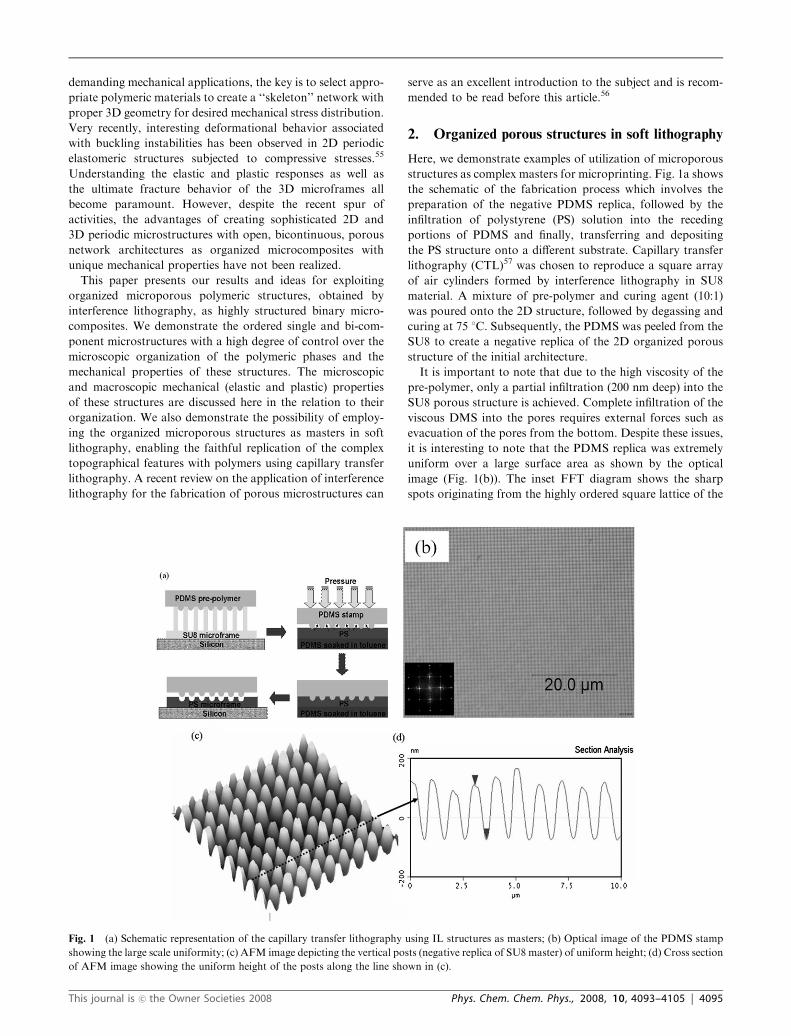
structures as complex masters for microprinting. Fig. 1a shows
the schematic of the fabrication process which involves the
preparation of the negative PDMS replica, followed by the
infiltration of polystyrene (PS) solution into the receding
portions of PDMS and finally, transferring and depositing
the PS structure onto a different substrate. Capillary transfer
lithography (CTL)57 was chosen to reproduce a square array
of air cylinders formed by interference lithography in SU8
material. A mixture of pre-polymer and curing agent (10:1)
was poured onto the 2D structure, followed by degassing and
curing at 75 1C. Subsequently, the PDMS was peeled from the
SU8 to create a negative replica of the 2D organized porous
structure of the initial architecture.
It is important to note that due to the high viscosity of the
pre-polymer, only a partial infiltration (200 nm deep) into the
SU8 porous structure is achieved. Complete infiltration of the
viscous DMS into the pores requires external forces such as
evacuation of the pores from the bottom. Despite these issues,
it is interesting to note that the PDMS replica was extremely
uniform over a large surface area as shown by the optical
image (Fig. 1(b)). The inset FFT diagram shows the sharp
spots originating from the highly ordered square lattice of the
Fig. 1 (a) Schematic representation of the capillary transfer lithography using IL structures as masters; (b) Optical image of the PDMS stamp
showing the large scale uniformity; (c) AFM image depicting the vertical posts (negative replica of SU8 master) of uniform height; (d) Cross section
of AFM image showing the uniform height of the posts along the line shown in (c).
This journal is �c the Owner Societies 2008 Phys. Chem. Chem. Phys., 2008, 10, 4093–4105 | 4095
arrays of vertical posts fabricated with this approach. More-
over, AFM image (Fig. 1(c)) shows a very uniform height of
the vertical posts and the cross section of a post row shows the
height to be nearly 200 nm for most of these posts.
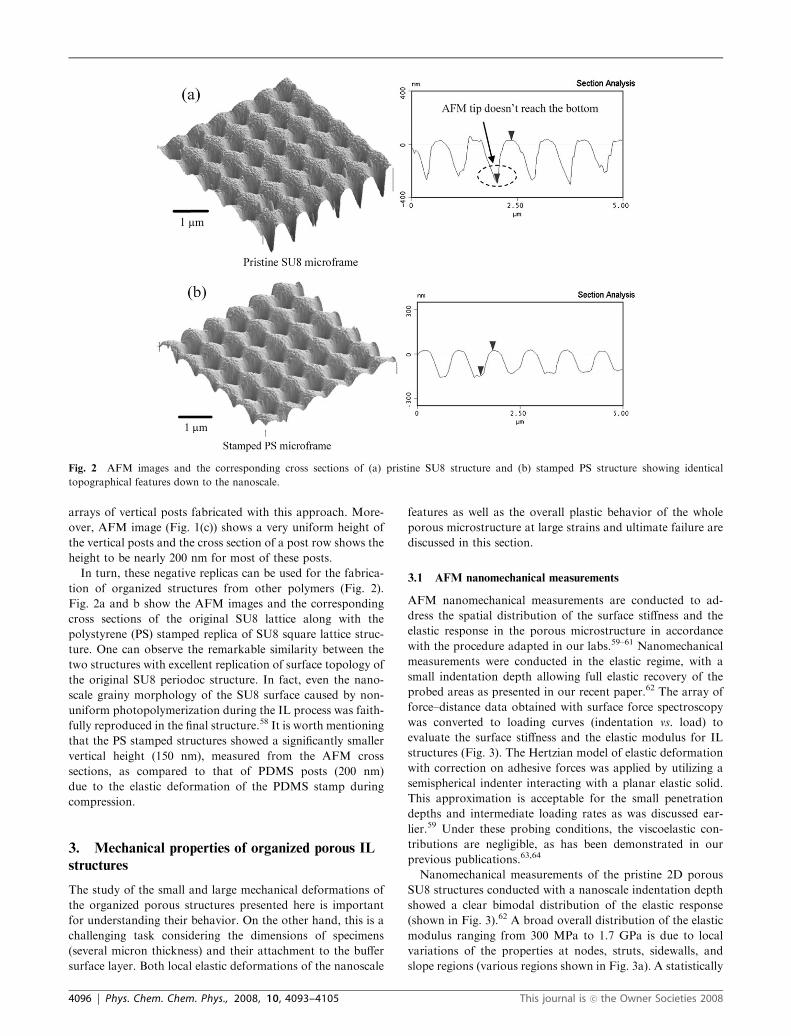
In turn, these negative replicas can be used for the fabrica-
tion of organized structures from other polymers (Fig. 2).
Fig. 2a and b show the AFM images and the corresponding
cross sections of the original SU8 lattice along with the
polystyrene (PS) stamped replica of SU8 square lattice struc-
ture. One can observe the remarkable similarity between the
two structures with excellent replication of surface topology of
the original SU8 periodoc structure. In fact, even the nano-
scale grainy morphology of the SU8 surface caused by non-
uniform photopolymerization during the IL process was faith-
fully reproduced in the final structure.58 It is worth mentioning
that the PS stamped structures showed a significantly smaller
vertical height (150 nm), measured from the AFM cross
sections, as compared to that of PDMS posts (200 nm)
due to the elastic deformation of the PDMS stamp during
compression.
3. Mechanical properties of organized porous IL
structures
The study of the small and large mechanical deformations of
the organized porous structures presented here is important
for understanding their behavior. On the other hand, this is a
challenging task considering the dimensions of specimens
(several micron thickness) and their attachment to the buffer
surface layer. Both local elastic deformations of the nanoscale
features as well as the overall plastic behavior of the whole
porous microstructure at large strains and ultimate failure are
discussed in this section.
3.1 AFM nanomechanical measurements
AFM nanomechanical measurements are conducted to ad-
dress the spatial distribution of the surface stiffness and the
elastic response in the porous microstructure in accordance
with the procedure adapted in our labs.59–61 Nanomechanical
measurements were conducted in the elastic regime, with a
small indentation depth allowing full elastic recovery of the
probed areas as presented in our recent paper.62 The array of
force–distance data obtained with surface force spectroscopy
was converted to loading curves (indentation vs. load) to
evaluate the surface stiffness and the elastic modulus for IL
structures (Fig. 3). The Hertzian model of elastic deformation
with correction on adhesive forces was applied by utilizing a
semispherical indenter interacting with a planar elastic solid.
This approximation is acceptable for the small penetration
depths and intermediate loading rates as was discussed ear-
lier.59 Under these probing conditions, the viscoelastic con-
tributions are negligible, as has been demonstrated in our
previous publications.63,64
Nanomechanical measurements of the pristine 2D porous
SU8 structures conducted with a nanoscale indentation depth
showed a clear bimodal distribution of the elastic response
(shown in Fig. 3).62 A broad overall distribution of the elastic
modulus ranging from 300 MPa to 1.7 GPa is due to local
variations of the properties at nodes, struts, sidewalls, and
slope regions (various regions shown in Fig. 3a). A statistically
Fig. 2 AFM images and the corresponding cross sections of (a) pristine SU8 structure and (b) stamped PS structure showing identical
topographical features down to the nanoscale.
4096 | Phys. Chem. Chem. Phys., 2008, 10, 4093–4105 This journal is �c the Owner Societies 2008

significant difference of the elastic modulus between nodes and
beams was confirmed by the high resolution mapping of
surface elastic properties (a single pixel of about 15 nm)
(Fig. 3b and c). The average elastic modulus obtained from
these histograms (Fig. 3d) for the nodes was 1480 MPa, which
is higher than the calculated value for the beam areas
(1120 MPa) due to periodic variation of the light intensity in
the course of fabrication. Such a spatial variation is, probably,
a very common feature which should be expected for any
microstructure fabricated by interference lithography with
continuously variable light intensity and thus continuously
variable crosslinking density.62
3.2 Large strain tensile measurements
However, highly localized AFM nanomechanical measure-
ments provide little insight into the mechanical behavior at a
macroscopic scale and for large deformations, which are
relevant to the integrated mechanical applications. Therefore,
microtensile tests were designed and performed on a 2D
square lattice SU8 sample of 2 mm thickness with pores of
380 nm in diameter and with a spacing of 830 nm with effective
porosity close to 20% (see Fig. 2a for surface topography).
Freestanding samples (0.9 cm � 0.3 cm � 2 mm) were mounted
onto standard microtensile sample holders. Tensile measure-
ments were performed with a force resolution of 3.5 mN and at
a strain rate of 10�3 s�1.
Fig. 4a and b show a stress and strain plot obtained under
uniaxial tensile loading. The shaded area on this plot indicates
continuous elastic resistance. Several spikes correspond to the
formation of straight transversal cracks formed by gradual
fracturing of the struts (Fig. 4c and d). The crack formation
might be preceded by a local necking of the struts (Fig. 4d).
However, the unperturbed regions still remain in the elastic
regime as can be seen by the elastic response following the
spikes. Sharp and multiple yield points correspond to the
initiation and propagation of straight microcracks perpendi-
cular to the stress direction (see representative cracks in Fig. 4c
and d). Each straight crack causes the number of load bearing
struts to decrease, which in turn lowers the effective modulus
of the whole microstructure (see changes in slope in Fig. 4b).
Such an unusual, stepwise mechanical deformation and frac-
turing is caused by a highly organized porous microstructure
with a square lattice and only a few cracks required for sample
fracturing. It is worth noting that similar load drops are
observed in the polymer samples subjected to uniaxial and
Fig. 3 (a) AFM topographic image of the 2D hexagonal lattice identifying the nodes (N) and beams (B) (b) 32 � 32 topography and (c) elastic
modulus collected during force micromapping of the 2.5 � 2.5 mm2 surface area (two designated areas are marked by squares of pixels (blue for
nodes (N) and red for beams (B)); (d) combined surface histograms collected for selected surface areas (500 � 500 nm2) for nodes (black boxes) and
beams (gray boxes) (reprinted from ref. 62).
This journal is �c the Owner Societies 2008 Phys. Chem. Chem. Phys., 2008, 10, 4093–4105 | 4097

high rate tensile strain due to initiation and localization of
plastic deformation for highly inhomogeneous deformation at
high strain rates (104–105 s�1).65 The stress–strain behavior
shows an interesting effect: after the highest yield point (at 13
MPa), prolonged necking occurs before the ultimate failure.
Overall, the 2D square lattice structure exhibited remark-
ably high ultimate strain, reaching 35% which is very unchar-
acteristic behavior for homogeneous SU8 material with a high
degree of crosslinking which is usually relatively brittle with
small elongation to break (o5%).66 Such large plastic defor-
mation can be observed only for IL structures with very fine
struts (Fig. 4d) with a diameter of several hundred nanometers
and can be related to scale-controlled elasticity of modestly
crosslinked elements of IL microstructures.56 Such a pro-
longed necking of the fine struts under extended deformation
provides extremely high toughness to these structures reaching
high values of 1.5 MJ m�3. The toughness of these structures
measured here is nearly five times higher as compared to the
random mats from drag line silk fibroin materials and layer-
by-layer thin films, asserting the efficient energy absorption of
the gradiently crosslinked SU8 microframe structures.67,68
The elastic modulus of the 2D SU8 square lattice structure
was calculated from the initial slope of the stress-strain curve
to be 0.5 GPa. This value is much lower than that usually
reported for the bulk SU8 material (2–4 GPa) and can be
associated with porous architecture of these specimens
(Fig. 5(a)).66 In fact, it is known that for cellular foam
materials with a square lattice of air columns, the elastic
modulus of the structure is anisotropic and is much lower
than that for struts.27 Indeed, the elastic modulus of the
structure along [10] and [11] directions is given by E½10� ¼Es
tl
� �and E½11� ¼ 2Es
tl
� �3where Es is the elastic modulus of the
cell wall material, ‘t’ is the strut wall thickness, and ‘l’ is the
distance between the adjacent struts (as schematically shown
in Fig. 5b). For the 2D microframe investigated here, t = 330
nm, l = 500 nm and the elastic modulus of the SU8 material
after IL fabrication is 1.1 GPa (see above). Thus, the effective
elastic modulus of the microframe along [10] direction should
be reduced to 0.7 GPa, which is close to the experimentally
determined value of 0.5 GPa for the initial stage of the elastic
stretching.
3.3 Fracture behavior of the organized porous structures
The ultimate performance of microframe structures can also
be addressed using a simple peeling process that involves
adhering an adhesive tape to the structure and peeling off a
portion of the film from the substrate.69 The remaining film is
then transferred onto a carbon tape and mounted in an SEM
holder. This peeling test involves a complex interplay of forces
and allows us to observe the mechanical response of the
microframe structure in a wide variety of deformational
Fig. 4 (a) Stress–strain plot of tensile measurement performed on a 2D SU8 microframe, showing the multiple yield points followed by prolonged
necking; (b) linear region of the stress-strain plot showing multiple yield points; (c) SEM image of the sample subjected to tensile measurement
showing the crack propagation along [1 0] direction; (d) SEM image showing the necking and large plastic deformation of the struts.
4098 | Phys. Chem. Chem. Phys., 2008, 10, 4093–4105 This journal is �c the Owner Societies 2008

modes. We thus see the combined effect of tension, bending,
compression, buckling, and shearing on our samples.
Inspection of the fractured film after this peeling procedure
reveals a host of interesting deformed and fractured morpho-
logies caused by various types of plastic deformations. Fea-
tures associated with failure include long, straight, micro-
meter-wide cracks following particular lattice and easy-
fracture directions, [10] and [01] directions in square lattice
(see Fig. 6a). The lines of easy fracture always involve the
failure of the thin, transversely oriented fine struts in the 2D
lattice as has been discussed in detail in our recent paper.69
Fig. 6b shows two other important modes of plastic defor-
mation of the 2D sample under compression. The 2D micro-
frame compressed laterally undergoes the collapse of the
square lattice of cylindrical pores, forming a stack of thin
wavy sheets. Furthermore, the stacks can undergo lateral
compression in the perpendicular direction to the initial
compressive forces resulting in correlated wrinkling in the
plane of the lattice (Fig. 6c). Collapse of the struts and
buckling of the thin walls are two efficient energy absorbing
mechanisms playing a significant role in the deformation of
these organized microstructures.
It is known that buckling of the cell walls in macroscopic
cellular structures can occur in two distinct modes: creep
buckling and catastrophic buckling.27 Creep buckling of the
wall involves the uniform sinusoidal deformation of structure,
while catastrophic buckling involves acute curvature of the
walls. Fig. 6b shows the uniform sinusoidal buckling of the
thin wall structures which can be related to the creep buckling
of the SU8 material. During the peel process, the microframe
structure possibly undergoes lateral compression resulting in
an in-plane periodic wrinkling pattern initiation. Upon further
compression, the deformation of the lattice is localized within
very short regions leading to a catastrophic buckling with
sharp curvature. Such catastrophic buckling modes were ob-
served in the fractured samples (Fig. 6c). It is important to
note that various modes of deformation such as compression
of the struts, sinusoidal buckling, and catastrophic buckling of
the SU8 thin plates, are all plastic in nature. These large plastic
deformations of the struts bridging the crack result in large
absorption of strain energy as observed in tensile measure-
ments causing high toughness reaching 1.5 MJ m�3 (as was
discussed above).
4. Bi-component organized IL structures
4.1 Infiltration of a second phase into open porous structures
Combining hard and soft polymer components (glassy-rub-
bery) provides advanced materials and coatings with syner-
getic properties and is frequently utilized for design of
advanced polymeric composites.70 For instance, a strong
matrix serves as a load-bearing skeleton for structural integ-
rity, while the soft component can be responsible for the
adhesion control or for crack arresting. As is known, to
achieve proper multiphase structure in conventional compo-
site materials, a complex monitoring of the kinetics of phase
separation of different components is required, as controlled
by multiple processing stages (e.g., adding a new component,
temperature variation). Although a certain control of spatial
scale, morphology, microstructure, and shape is achieved with
temperature–composition variation, the resulting composites
usually possess a high variation of feature dimensions, topol-
ogy, and composition. These variations of structural para-
meters make it difficult to prevent a wide fluctuation of
physical properties. While such a behavior affects the macro-
scopic properties of bulk composites to some extent, it can be
much more critical for organized microstructural materials
with overall dimensions (e.g., thickness) comparable to the
microphase domain dimensions (e.g., polymer MEMS with
sub-micron elements).
In view of the above consideration, we suggest that the
organized porous IL structure can serve as an organized
matrix for the fabrication of microcomposite materials with
well-defined, uniform, and pre-determined spatial distribution
of components or microphases. To implement this strategy, we
have applied two independent approaches to infiltrate the
second rubbery polymeric phase into the SU8 glassy micro-
frame structure, namely, capillary driven infiltration of poly-
mers and in situ polymerization in the microframe structure.
Fig. 5 (a) AFM image identifying the struts and the nodes of the 2D square lattice SU8 microframe; (b) schematic representation of unit cell of
2D square lattice and the elastic moduli in the two characteristic directions.
This journal is �c the Owner Societies 2008 Phys. Chem. Chem. Phys., 2008, 10, 4093–4105 | 4099

In the first method, capillary infiltration of the polymer was
employed to fill the 2D open porous SU8 structure, as
schematically represented in Fig. 7. The capillary force infil-
tration method uses capillary-driven filling of polymers sof-
tened by solvent (lowering the viscosity). The second polymer
component (2% polybutadiene (PB) in toluene) is spin coated
onto the PDMS substrate swollen in toluene. Swelling the
substrate in toluene continuously supplies the solvent, soft-
ening the spin cast PB rubbery layer. Upon bringing the SU8
porous microstructure into intimate contact with the PDMS
substrate, the PB solution fills the recessed region of the
cylindrical pores (Fig. 7).
This method offers relatively uniform infiltration of the
rubbery phase into the glassy polymer structure with cylind-
rical pores as illustrated by Fig. 8. One of the distinct
advantages of the method is that it results in structures with
pristine SU8 surface (with no residues of PB material on the
SU8 surface). Fig. 8a and b show the AFM topography and
phase images of the binary infiltrated structure, clearly depict-
ing the distinct SU8 original structure (square matrix) and PB
phase. The low surface energy of the PDMS substrate results
in a poor interaction with PB, enabling the formation of
Fig. 7 Schematic representation of the capillary force assisted infil-
tration of PB solution into the SU8 porous structure.
Fig. 8 AFM images depicting the SU8/PB bicomponent microstruc-
ture: (a) topography showing the uniform infiltration into the micro-
frame (Z range: 100 nm); (b) phase image depicting the alternating
bicomponent structure (phase scale: 501).
Fig. 6 SEM image showing fracture behavior of the 2D SU8 microframe: (a) fracture of 2D structure along the easy crack lines; (b) penny shaped
cracks and sinusoidal buckling in the 2D microframe sample under compressive stress; (c) compressed regions of the microframe undergoing
catastrophic buckling. Arrows indicate the direction of compression; (d) ultimate fracture of the compressed walls leading to the failure of the
structure.
4100 | Phys. Chem. Chem. Phys., 2008, 10, 4093–4105 This journal is �c the Owner Societies 2008
checkerboard PB-SU8 surface composition in the final
structure.
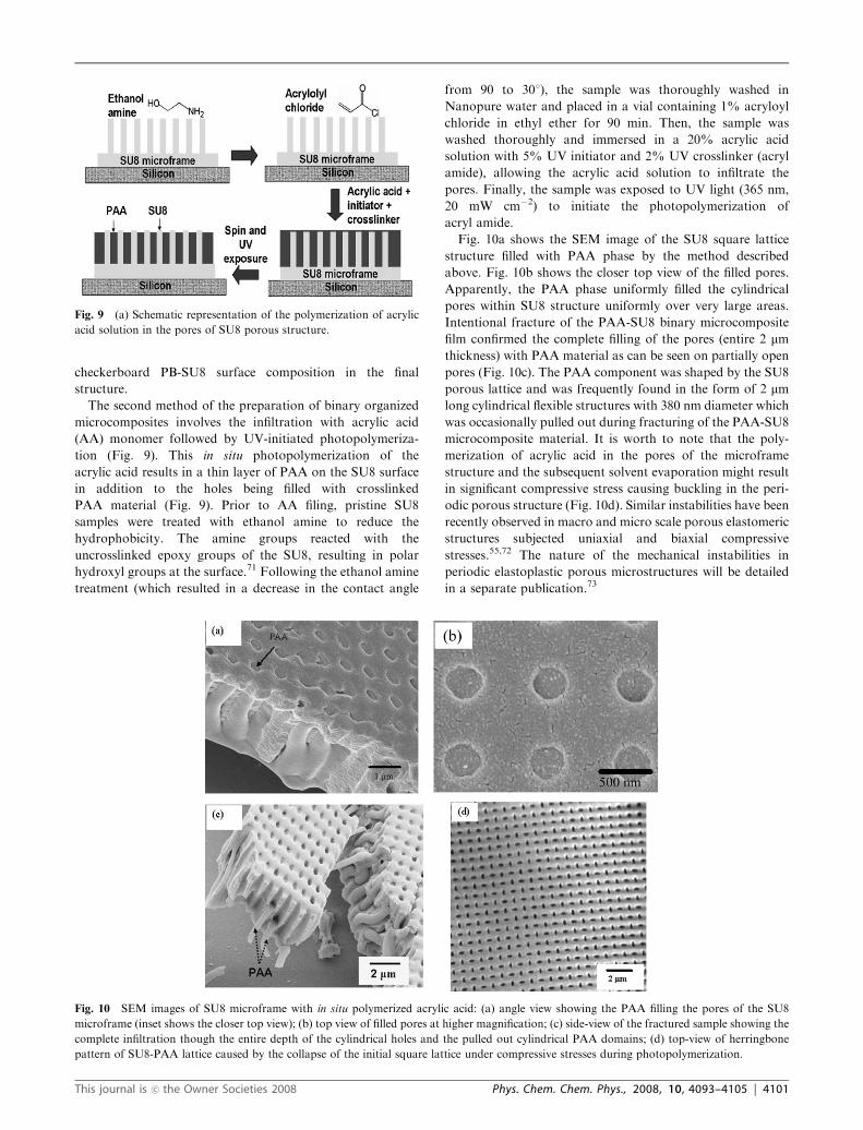
The second method of the preparation of binary organized
microcomposites involves the infiltration with acrylic acid
(AA) monomer followed by UV-initiated photopolymeriza-
tion (Fig. 9). This in situ photopolymerization of the
acrylic acid results in a thin layer of PAA on the SU8 surface
in addition to the holes being filled with crosslinked
PAA material (Fig. 9). Prior to AA filing, pristine SU8
samples were treated with ethanol amine to reduce the
hydrophobicity. The amine groups reacted with the
uncrosslinked epoxy groups of the SU8, resulting in polar
hydroxyl groups at the surface.71 Following the ethanol amine
treatment (which resulted in a decrease in the contact angle
from 90 to 301), the sample was thoroughly washed in
Nanopure water and placed in a vial containing 1% acryloyl
chloride in ethyl ether for 90 min. Then, the sample was
washed thoroughly and immersed in a 20% acrylic acid
solution with 5% UV initiator and 2% UV crosslinker (acryl
amide), allowing the acrylic acid solution to infiltrate the
pores. Finally, the sample was exposed to UV light (365 nm,
20 mW cm�2) to initiate the photopolymerization of
acryl amide.
Fig. 10a shows the SEM image of the SU8 square lattice
structure filled with PAA phase by the method described
above. Fig. 10b shows the closer top view of the filled pores.
Apparently, the PAA phase uniformly filled the cylindrical
pores within SU8 structure uniformly over very large areas.
Intentional fracture of the PAA-SU8 binary microcomposite
film confirmed the complete filling of the pores (entire 2 mmthickness) with PAA material as can be seen on partially open
pores (Fig. 10c). The PAA component was shaped by the SU8
porous lattice and was frequently found in the form of 2 mmlong cylindrical flexible structures with 380 nm diameter which
was occasionally pulled out during fracturing of the PAA-SU8
microcomposite material. It is worth to note that the poly-
merization of acrylic acid in the pores of the microframe
structure and the subsequent solvent evaporation might result
in significant compressive stress causing buckling in the peri-
odic porous structure (Fig. 10d). Similar instabilities have been
recently observed in macro and micro scale porous elastomeric
structures subjected uniaxial and biaxial compressive
stresses.55,72 The nature of the mechanical instabilities in
periodic elastoplastic porous microstructures will be detailed
in a separate publication.73
Fig. 9 (a) Schematic representation of the polymerization of acrylic
acid solution in the pores of SU8 porous structure.
Fig. 10 SEM images of SU8 microframe with in situ polymerized acrylic acid: (a) angle view showing the PAA filling the pores of the SU8
microframe (inset shows the closer top view); (b) top view of filled pores at higher magnification; (c) side-view of the fractured sample showing the
complete infiltration though the entire depth of the cylindrical holes and the pulled out cylindrical PAA domains; (d) top-view of herringbone
pattern of SU8-PAA lattice caused by the collapse of the initial square lattice under compressive stresses during photopolymerization.
This journal is �c the Owner Societies 2008 Phys. Chem. Chem. Phys., 2008, 10, 4093–4105 | 4101
5. Mechanical behavior of bi-component ITL
structures
5.1 AFM micromechanical measurements
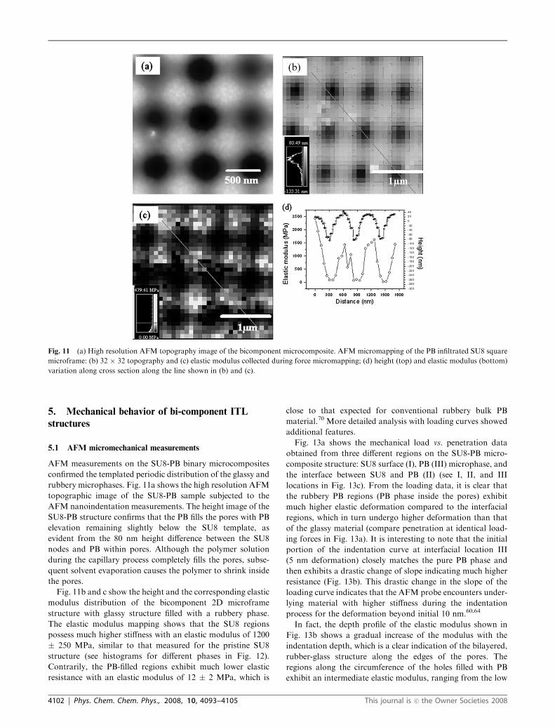
AFM measurements on the SU8-PB binary microcomposites
confirmed the templated periodic distribution of the glassy and
rubbery microphases. Fig. 11a shows the high resolution AFM
topographic image of the SU8-PB sample subjected to the
AFM nanoindentation measurements. The height image of the
SU8-PB structure confirms that the PB fills the pores with PB
elevation remaining slightly below the SU8 template, as
evident from the 80 nm height difference between the SU8
nodes and PB within pores. Although the polymer solution
during the capillary process completely fills the pores, subse-
quent solvent evaporation causes the polymer to shrink inside
the pores.
Fig. 11b and c show the height and the corresponding elastic
modulus distribution of the bicomponent 2D microframe
structure with glassy structure filled with a rubbery phase.
The elastic modulus mapping shows that the SU8 regions
possess much higher stiffness with an elastic modulus of 1200
� 250 MPa, similar to that measured for the pristine SU8
structure (see histograms for different phases in Fig. 12).
Contrarily, the PB-filled regions exhibit much lower elastic
resistance with an elastic modulus of 12 � 2 MPa, which is
close to that expected for conventional rubbery bulk PB
material.70 More detailed analysis with loading curves showed
additional features.
Fig. 13a shows the mechanical load vs. penetration data
obtained from three different regions on the SU8-PB micro-
composite structure: SU8 surface (I), PB (III) microphase, and
the interface between SU8 and PB (II) (see I, II, and III
locations in Fig. 13c). From the loading data, it is clear that
the rubbery PB regions (PB phase inside the pores) exhibit
much higher elastic deformation compared to the interfacial
regions, which in turn undergo higher deformation than that
of the glassy material (compare penetration at identical load-
ing forces in Fig. 13a). It is interesting to note that the initial
portion of the indentation curve at interfacial location III
(5 nm deformation) closely matches the pure PB phase and
then exhibits a drastic change of slope indicating much higher
resistance (Fig. 13b). This drastic change in the slope of the
loading curve indicates that the AFM probe encounters under-
lying material with higher stiffness during the indentation
process for the deformation beyond initial 10 nm.60,64
In fact, the depth profile of the elastic modulus shown in
Fig. 13b shows a gradual increase of the modulus with the
indentation depth, which is a clear indication of the bilayered,
rubber-glass structure along the edges of the pores. The
regions along the circumference of the holes filled with PB
exhibit an intermediate elastic modulus, ranging from the low
Fig. 11 (a) High resolution AFM topography image of the bicomponent microcomposite. AFM micromapping of the PB infiltrated SU8 square
microframe: (b) 32 � 32 topography and (c) elastic modulus collected during force micromapping; (d) height (top) and elastic modulus (bottom)
variation along cross section along the line shown in (b) and (c).
4102 | Phys. Chem. Chem. Phys., 2008, 10, 4093–4105 This journal is �c the Owner Societies 2008

elastic modulus of PB (about 12 MPa) to a few hundred MPas
(combined PB and SU8). This variation is caused by the
interaction of the AFM tip with both materials in this transi-
tions region with the presence of ultrathin (10 nm) surface PB
layer covering SU8 material. Indeed, the concurrent cross
section of the height and elastic modulus distribution (along
the lines shown in Fig. 11a and b) demonstrated a gradual
variation of the elastic response instead of abrupt transition
across the pore rims (Fig. 11d). The presence of PB phase at
the edges of the cylindrical pores resulted in the gradient of
elastic modulus observed in this study and confirmed the
general schematics of the distribution of glassy matrix and
rubbery phase in the bicomponent SU8-PB microframe
presented in Fig. 13c.
5.2 Fracture behavior of rubber-filled glassy IL structures
The peel test has been applied to study the fracture behavior of
the PAA-SU8 binary microcomposite with 2D square sym-
metry. SEM images show the fractured areas of the PAA-SU8
sample exhibiting a fundamentally different deformation be-
havior compared to the original porous SU8 structure
(Fig. 14). Both the SU8 struts and the PAA domains are
stretched during the crack propagation, as can be seen in
Fig. 14b. For these organized microcomposites, the cracks
propagate exclusively along the [10] direction of the square
lattice similar to that discussed above. However, unlike initial
porous structure, the rubbery microphases are stretched across
the crack at very high elongation even after all SU8 struts of
the matrix failed, thus, effectively bridging the opening at very
high deformations (Fig. 14a). Rubbery PAA phase inside of
cylindrical pores stretched across the crack openings exhibits
significantly higher deformation (reaching 300–400%) com-
pared to the SU8 struts (usually below 35% ultimate elonga-
tion). This way, the crack propagation is arrested by the
stretched rubber microphases bridging across the SU8 edges,
resembling the known crazing phenomenon in conventional
rubber-toughened composite materials with ultimate
toughness such as ABS plastics.74
The unique feature of the organized PAA-SU8 structure is
that the crack follows the selected lattice direction fracturing
the PAA phase inside of cylindrical pores. This stretching of
the PAA phase beyond failed struts should result in additional
dissipation of strain energy at ultimate deformation conditions
in a very different way as compared to conventional micro-
composites. Indeed, in the case of the randomly distributed
rubbery microphases, there are multiple random pathways in
which the crack can propagate through glassy phase dissipat-
ing the least amount of mechanical energy and causing the
macroscopic failure of the randommicrostructure. In contrast,
for the organized bi-component rubbery-glassy structures
discussed here, the crack’s pathway through the rubbery-filled
pores is predetermined by the matrix symmetry (square lattice
in this case), which could possibly maximize energy dissipation
during crack propagation. By directing the crack opening in
the direction with maximized presence of the rubbery
microphase inclusions.
It is worth to note that in the bicomponent microcompo-
sites, we have primarily observed that the PAA domains
stretch as opposed to the cavitation in the conventional
composites.70 The possible reason for the absence of cavitation
in bicomponent microcomposites studied here might be the
length-scale dependent mechanical properties of the SU8. It is
known that one of the primary reasons for the cavitation of
the rubber particles is the brittle nature of the surrounding
matrix which facilitates significant difference in crack propa-
gation velocities in glassy and rubbery regions. However, the
IL crosslinked SU8 epoxy matrix can undergo significant
plastic yielding (35% strain, as estimated from tensile test)
before failure as opposed to the brittle fracture (o2% strain)
in the case of the conventional highly crosslinked epoxy
matrix. Moreover, in the case of the conventional rubber
toughened composites, the rubber domains are separated by
a few microns as opposed to the submicron separation in the
case of the bicomponent microcomposite system (about
450 nm in our case). Thus the length scale dependent mechan-
ical behavior of the matrix (microframe) might result in
fundamentally different energy absorption mechanism in mul-
ticomponent organized microcomposites. Finally, it is impor-
tant to note that the rubber domains stretching and bridging
across the crack is an efficient energy absorption mechanism.
Quantitative characterization of the toughness of the rubber
filled microcomposites at different strain rates and with vary-
ing pore sizes is a subject of further investigation focused on
understanding the energy dissipation characteristics in orga-
nized rubbery-glassy microcomposite materials.
Fig. 12 Histograms showing the surface distribution of the elastic
modulus in the SU8 and PB phases of the bi-component structure.
This journal is �c the Owner Societies 2008 Phys. Chem. Chem. Phys., 2008, 10, 4093–4105 | 4103

6. Conclusions
In conclusion, we have demonstrated that organized porous
microstructures with continuous open microscopic pores ob-
tained via interference lithography can be successfully utilized
in the form of complex porous matrices for the fabrication of
binary organized microcomposites with intriguing mechanical
properties, such as lattice-controlled crack propagation, high
toughness, and high energy dissipation due to multiple failures
of struts and rubbery domains. Such organized glassy-rubbery
microcomposites fabricated with IL can find novel high-de-
manding applications, which require precise control of
the mechanical elastic and plastic behavior at micro and
nanoscale.
Acknowledgements
The work presented here is supported by NSF-CMS-0709586
and Institute for Soldier Nanotechnologies of the US Army
Fig. 13 (a) Representative loading curves from three different regions (SU8 (I), PB (III) and interface (II) as shown in (c)) of the bicomponent
microcomposite; (b) depth profile of the elastic modulus at the interface of SU8 and PB (along the rim of the pore) showing the increasing elastic
modulus with indentation depth; (c) the PB microphase in the SU8 pore showing the thin layer of PB on SU8 matrix along the circumference.
Fig. 14 SEM images showing the fracture in bicomponent SU8-PAA structures: (a) PAA inside the holes stretching (B300%) and forming fibrils
across the crack; (b) Crack bisecting the rubbery PAA domains inside the porous matrix.
4104 | Phys. Chem. Chem. Phys., 2008, 10, 4093–4105 This journal is �c the Owner Societies 2008

Research Office (under Contract DAAD-19-02-0002). The
authors would like to thank Dr Melburne LeMieux, Dr Taeyi
Choi, Dr Chaitanya Ullal, for discussions and Prof. Satish
Kumar, Dr Hyunhyub Ko, Dr Sergiy Peleshanko and Han Gi
Chae for technical assistance.
References
1. Y. N. Xia, B. Gates, Y. D. Yin and Y. Lu,Adv.Mater., 2000, 12, 693.2. P. T. Tanev, M. Chibwe and T. J. Pinnavaia, Nature, 1994, 368, 321.3. D. B. Akolekar, A. R. Hind and S. K. Bhargava, J. Colloid
Interface Sci., 1998, 199, 92.4. S. F. Xie, F. Svec and J. M. J. Frechet, J. Chromatogr., A, 1997,
775, 65.5. W. Busby, N. R. Cameron and C. A. B. Jahoda, Polym. Interface,
2002, 51, 871.6. T. Nishikawa, J. Nishida, R. Ookura, S. I. Nishimura, S. Wada
and T. Karino, Mater. Sci. Eng., C, 1999, 8–9, 495.7. D. van Noort and C. F. Mandenius, Biosens. Bioelectron., 2000,
15, 203.8. V. Malyarchuk, M. E. Stewart, R. G. Nuzzo and J. A. Rogers,
Appl. Phys. Lett., 2007, 90, 203113.9. Micro- and Nanosystems: Information Storage and Processing
Systems, ed. B Bhushan, Springer, Berlin, Heidelberg, 2002.10. Microstructure and Microtribology of Polymer Surfaces, ed.
V. V. Tsukruk and K Wahl, ACS Symposium Series, vol. 741, 2000.11. I. Luzinov, S. Minko and V. V. Tsukruk, Prog. Polym. Sci., 2004,
29, 635.12. C. Liu, Adv. Mater., 2007, 19, 3783.13. H. Lorenz, M. Despont, N. Fahrni, N. LaBianca, P. Renaud and
P. Vettiger, J. Micromech. Microeng., 1997, 7, 121.14. N. T. Nguyen and T. Q. Truong, Sens. Actuators, B, 2004, 97, 137.15. V. Seidemann, S. Butefisch and S. Buettgenbach, Sens. Actuators,
A, 2002, 97, 457.16. H. Yu, O. Balogun, B. Li, T. W. Murray and X. Zhang,
J. Micromech. Microeng., 2004, 14, 1576.17. H. Lorenz, M. Laudon and P. Renaud, Microelectron. Eng., 1998,
41, 371.18. R. G. Alargova, K. H. Bhatt, P. N. Paunov and O. D. Velev, Adv.
Mater., 2004, 16, 1653.19. S. Peleshanko, M. D. Julian, M. Ornatska, M. E. McConney,
M. C. LeMieux, N. Chen, C. Tucker, Y. Yang, C. Liu, J. A.C. Humphrey and V. V. Tsukruk, Adv. Mater., 2007, 19, 2903.
20. M. Calleja, J. Tamayo, A. Johansson, P. Rasmussen,L. M. Lechuga and A. Boisen, Sensor Lett., 2003, 1, 20.
21. R. Bandorf, H. Luthje, A. Wortmann, T. Staedler and R. Wittorf,Surf. Coat. Technol., 2003, 174, 461.
22. Y. Xia and G. M. Whitesides, Angew. Chem., Int. Ed. Engl., 199,37, 550.
23. Y. Xia, J. A. Rogers, K. E. Paul and G. M. Whitesides, Chem.Rev., 1999, 99, 1823.
24. B. D. Gates, Q. Xu, J. C. Love, D. B. Wolfe andG. M. Whitesides, Annu. Rev. Mater. Res., 2004, 34, 339.
25. M. Ulbricht, Polymer, 2006, 47, 2217.26. D. Zimnitsky, V. V. Shevchenko and V. V. Tsukruk, Langmuir,
2008, DOI: 10.1021/la7038575.27. L. J. Gibson and M. F. Ashby, Cellular Solids Structure and
Properties, Cambridge University Press, Cambridge, 2nd edn,1997.
28. V. S. Deshpande, N. A. Fleck and M. F. Ashby, J. Mech. Phys.Solids, 2001, 41, 1747.
29. N. Wicks and J. W. Hutchinson, Int. J. Solids Struct., 2001, 38,5165.
30. V. S. Deshpande, M. F. Ashby and N. A. Fleck, Acta Mater.,2001, 49, 1035.
31. A. G. Evans, J. W. Hutchinson, N. A. Fleck, M. F. Ashby andH. G. Wadley, Progr. Mater. Sci., 2001, 46, 309.
32. S. Yang, G. Chen, M. Megens, C. K. Ullal, Y. J. Han,R. Rapaport, E. L. Thomas and J. Aizenberg, Adv. Mater.,2005, 17, 435.
33. Cellular Ceramics: Structure, Manufacturing, Properties andApplications, ed. M Scheffler and P Colombo, Wiley, 2005.
34. S. Hyun, A. M. Karlsson, S. Torquato and A. G. Evans, Int. J.Solids Struct., 2003, 40, 6989.
35. O. D. Velev and E. W. Kaler, Adv. Mater., 2000, 12, 531.36. M. L. Kai Hoa, M. Lu and Y. Zhang, Adv. Colloid Interface Sci.,
2006, 121, 9.37. M. E. Leunissen, Nature, 2005, 437, 235.38. E. V. Shevchenko, J. Kortright, D. V. Talapin, S. Aloni and
A. P. Alivisatos, Adv. Mater., 2007, 19, 4183.39. S. A. Davis, S. L. Burkett, N. H. Mendelson and S. Mann,Nature,
1997, 385, 420.40. G. Cook, P. L. Timms and C. G. Spickermann, Angew. Chem.,
Int. Ed., 2003, 42, 557.41. Y.-H. Ha, R. A. Vaia, W. F. Lynn, J. P. Costantino, J. Shin,
A. B. Smith, P. T. Matsudaira and E. L. Thomas, Adv. Mater.,2004, 16, 1091.
42. J. Y. Huang, X. D. Wang and Z. L. Wang,Nano Lett., 2006, 6, 2325.43. M. Srinivasarao, D. Collings, A. Philips and S. Patel, Science,
2001, 292, 79.44. V. Z.-H. Chan, J. Hoffman, V. Y. Lee, H. Iatrou,
A. Avgeropoulos, N. Hadjichristidis, R. D. Miller andE. L. Thomas, Science, 1999, 286, 1716.
45. J.-H. Jang, C. K. Ullal, M. Maldovan, T. Gorishnyy, S. Kooi,C. Koh and E. L. Thomas, Adv. Func. Mater., 2007, 17, 3027.
46. J. H. Moon, J. Ford and S. Yang, Polym. Adv. Technol., 2006, 17, 83.47. J. H.Moon and S. Yang, J.Macromol. Sci., Polym. Rev., 2005,C45, 351.48. M. Maldovan, C. K. Ullal, W. C. Carter and E. L. Thomas, Nat.
Mater., 2003, 2, 664.49. C. K. Ullal, M. Maldovan, G. Chen, Y. Han, S. Yang and
E. L. Thomas, Appl. Phys. Lett., 2004, 84, 5434.50. D. Mei, B. Cheng, W. Hu, Z. Li and D. Zhang, Opt. Lett., 1995,
20, 429.51. M. Campbell, D. N. Sharp, M. T. Harrison, R. G. Denning and
A. J. Turberfield, Nature, 2000, 404, 53.52. S. Yang, M. Megens, J. Aizenberg, P. Witzius, P. M. Chaikin and
W. B. Russell, Chem. Mater., 2002, 14, 2831.53. B. Wagner, H. J. Quenzer, W. Henke, W. Hoppe and W. Pilz,
Sens. Actuators, A, 1995, A46, 89.54. J.-H. Jang, C. K. Ullal1, T. Gorishnyy, V. V. Tsukruk and
E. L. Thomas, Nano Lett., 2006, 6, 740.55. T. Mullin, S. Deschanel, K. Bertoldi and M. C. Boyce, Phys. Rev.
Lett., 2007, 99, 084301.56. J.-H. Jang, C. K. Ullal, M. Maldovan, T. Gorishnyy, S. Kooi,
C. Koh and E. L. Thomas, Adv. Funct. Mater., 2007, 17, 3027.57. H. Ko, C. Jiang and V. V. Tsukruk, Chem. Mater., 2005, 17, 5489.58. F. Hua, Y. Sun, A. Gaur, M. A. Meitl, L. Bilhaut, L. Rotkina,
J.Wang, P. Geil, M. Shim and J. A. Rogers,Nano Lett., 2004, 4, 2467.59. V. V. Tsukruk, Z. Huang, S. A. Chizhik and V. V. Gorbunov,
J. Mater. Sci., 1998, 33, 4905.60. H. Shulha, A. Kovalev, N. Myshkin and V. V. Tsukruk, Eur.
Polym. J., 2004, 40, 949.61. V. V. Tsukruk and Z. Huang, Polymer, 2000, 41, 5541.62. T. Choi, J.-H. Jang, C. K. Ullal, M. C. Lemieux, V. V. Tsukruk
and E. L. Thomas, Adv. Funct. Mater., 2006, 16, 1324.63. V. V. Tsukruk, V. V. Gorbunov, Z. Huang and S. A. Chizhik,
Polym. Int., 2000, 49, 441.64. A. Kovalev, H. Shulha, M. LeMieux, N. Myshkin and
V. V. Tsukruk, J. Mater. Res., 2004, 19, 716.65. S. Sarva, A. D.Mulliken andM. C. Boyce, J. Phys. IV, 2006, 134, 95.66. R. Feng and R. J. Farris, J. Mater. Sci., 2002, 37, 4793.67. R. V. Lewis, Chem. Rev., 2006, 106, 3762.68. C. Jiang, X. Wang, R. Gunawidjaja, Y.-H. Lin, M. K. Gupta,
D. L. Kaplan, R. R. Naik and V. V. Tsukruk, Adv. Funct. Mater.,2007, 17, 2229.
69. J.-H. Jang, C. K. Ullal, T. Choi, M. C. Lemieux, V. V. Tsukrukand E. L. Thomas, Adv. Mater., 2006, 18, 2123.
70. L. H. Sperling, Polymeric Multicomponent Materials, John Wiley& Sons, Inc., New York, 1997.
71. M. Nordstrom, R. Marie, M. Calleja and A. Boisen,J. Micromech. Microeng., 2004, 14, 1614.
72. Y. Zhang, E. A. Matsumoto, A. Peter, P.-C. Lin, R. D. Kamienand S. Yang, Nano Lett., 2008, 8, 1192.
73. S. Singamaneni, K. Bertoldi, S. Chang, J.-H. Jang, E. L. Thomas,M. Boyce and V. V. Tsukruk, Nat. Mater., submitted.
74. A. S. Argon, R. E. Cohen, O. S. Gebizlioglu and C. E. Schwier,Adv. Polym. Sci., 1983, 52–3, 275.
This journal is �c the Owner Societies 2008 Phys. Chem. Chem. Phys., 2008, 10, 4093–4105 | 4105