phys 645/445 electronics for scientists dr. jamie holder [email protected] jholder
TRANSCRIPT

Phys 645/445 Electronics for Scientists
Dr. Jamie [email protected]
http://www.physics.udel.edu/~jholder

Lecture 1 Overview
• Introductions
• Syllabus
• Course description
• Review of simple DC circuits

Who am I?
• Course Instructor: Dr. Jamie Holder• University of Leeds, UK: Physics with Astrophysics• University of Durham, UK: Gamma-Ray Astronomy• University of Tokyo, Japan: CANGAROO project• University of Paris, France: CELESTE project• University of Leeds, UK: VERITAS project• University of Delaware, USA: VERITAS project

VERITAS
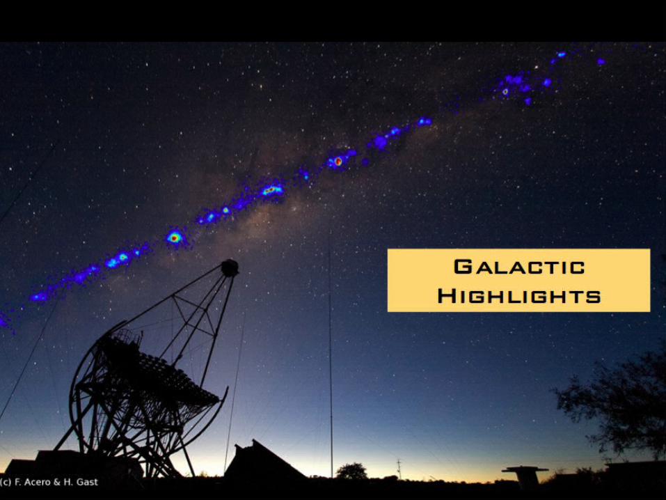
• Situated at 1250m altitude at the Whipple Observatory near Tucson
• All four telescopes operational since March 2007

VERITAS
• Use 12 meter diameter reflectors to detect gamma-rays (very high energy photons) from astrophysical sources (Supernova remnants, active galaxies, black holes, neutron stars)
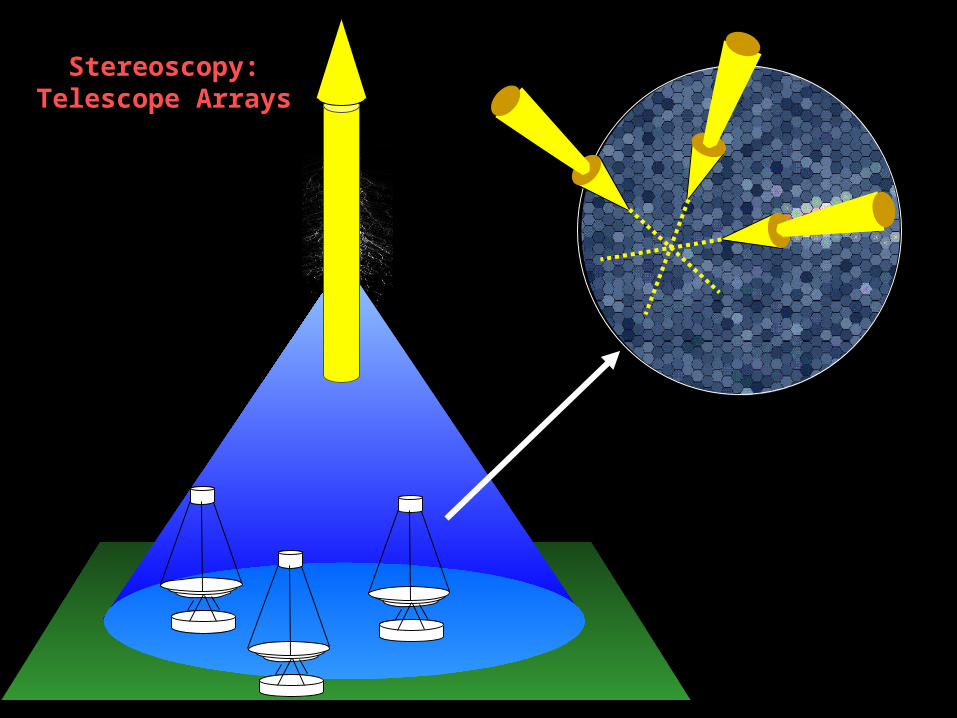
Stereoscopy: Stereoscopy: Telescope ArraysTelescope Arrays
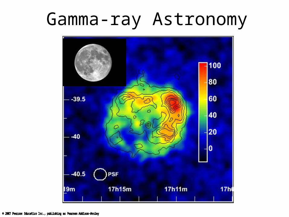
Gamma-ray Astronomy
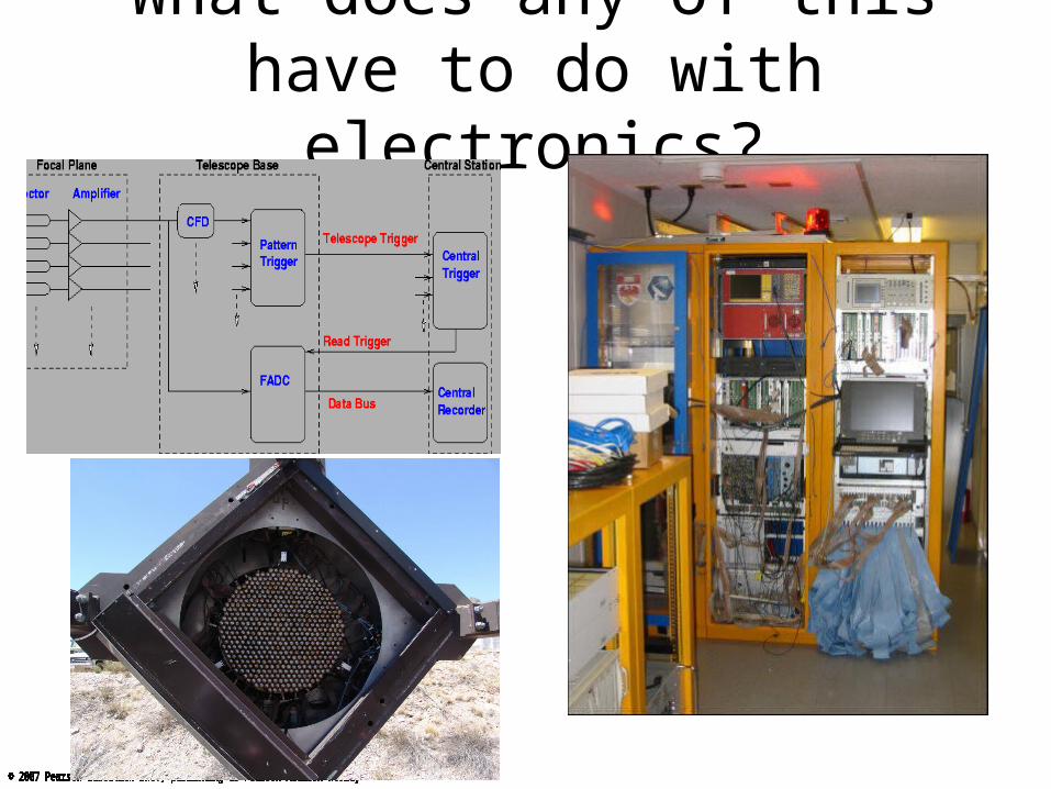
What does any of this have to do with electronics?

Who are you?
6 Grad students, 2 seniors, 1 sophomoreMajors: half Physics, half Mechanical Engineering …
What similar courses have you taken?
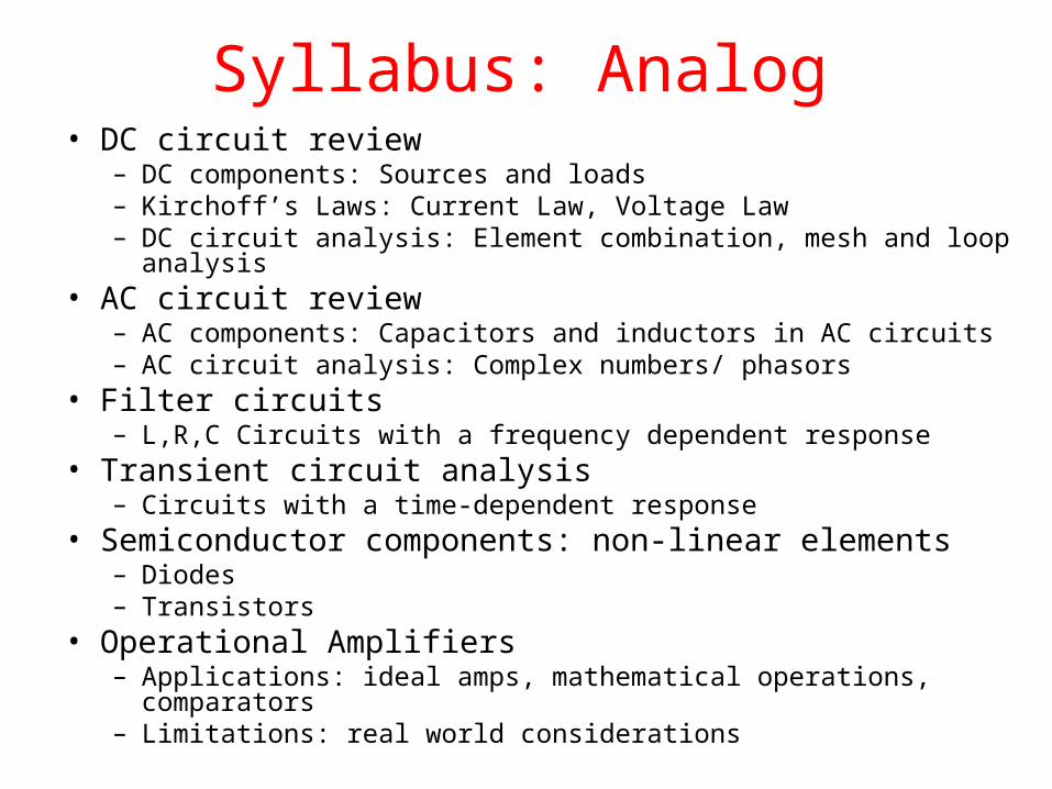
Syllabus: Analog• DC circuit review
– DC components: Sources and loads– Kirchoff’s Laws: Current Law, Voltage Law– DC circuit analysis: Element combination, mesh and loop analysis
• AC circuit review– AC components: Capacitors and inductors in AC circuits– AC circuit analysis: Complex numbers/ phasors
• Filter circuits– L,R,C Circuits with a frequency dependent response
• Transient circuit analysis– Circuits with a time-dependent response
• Semiconductor components: non-linear elements– Diodes– Transistors
• Operational Amplifiers– Applications: ideal amps, mathematical operations, comparators– Limitations: real world considerations

Syllabus: Digital• Digital Circuits
– Why digital?– Logic and Boolean algebra– CMOS gates– Digital Circuit design and analysis: Karnaugh Maps
• Combinational Logic– output depends on present inputs
• Sequential Logic– output depends on present and past inputs– Finite state machines: Mealy and Moore
• Wave Shaping– Producing, cleaning and modifying Digital pulses
• Analog – Digital conversion• Programmable logic devices and FPGAs

Reference materials
• No one book covers the whole course• Textbooks are not required, but recommended
useful texts include– D. Barnaal, “Analog Electronics for Scientific Application”– R.E. Simpson, “Introductory Electronics for Scientists
and Engineers”– Horowitz and Hill “The Art of Electronics”
• Reference copies available in the electronics lab• Lecture notes available on the web after the lecture• http://www.physics.udel.edu/~jholder/

Course Structure• Lab – 30%
– Work in pairs– Lab reports due one week after the lab– Pair reports acceptable (your choice)– Labs must be written up on a computer and include
• Introduction: Briefly describe why you are doing this lab, and what objectives are.• Experiment: Describe how you do the experiment.• Results: Present measured results• Analyses: Analyze the results and research the conclusions. Have you achieved your
objectives? How accurate are your results, what are the error sources, how would you improve the experiment, etc. This is the most important part. Bad experimental data or results do not mean you will get very bad grade. If you successfully point out where you went wrong, you may still get a good grade.
• Summary: Tell the readers a few (maybe just one) important findings from this experiment. Try to write in such a way that the reader will still learn a few things even he just reads this section of the report.
• Weekly assignments – 20% – Available from my web page (usually on Thursday)– Due in class on the day indicated (usually on Thursday)– Legible handwritten solutions OK – Draw circuits neatly. Show your working!
• Lab project – 20%• Mid-term Exam – 10%• Final Exam - 20%

Preliminary Grade scaleGrade scale
85% A
80% A-
75% B+
70% B
65% B-
60% C+
55% C
50% C-
45% D+
40% D

Good Lab Practice
• KEEP THE LAB TIDY. • Return components to their boxes.• Make circuits neat• Check circuit before turning power on• Remove power before changing circuit elements• Do not touch circuit with bare hands when the
power is on• Make sure the grounding is good• Do not short voltage sources or open current
sources

Good Lab Practice
BAD! GOOD!
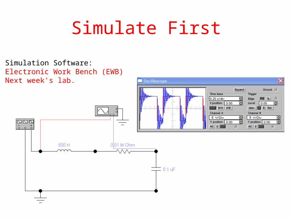
Simulate First
Simulation Software: Electronic Work Bench (EWB)Next week's lab.
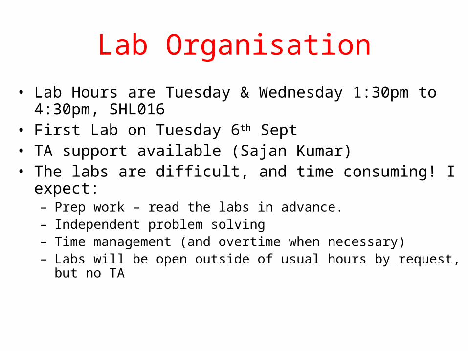
Lab Organisation
• Lab Hours are Tuesday & Wednesday 1:30pm to 4:30pm, SHL016
• First Lab on Tuesday 6th Sept• TA support available (Sajan Kumar)• The labs are difficult, and time consuming! I expect:
– Prep work – read the labs in advance.– Independent problem solving– Time management (and overtime when necessary)– Labs will be open outside of usual hours by request, but no TA

Lab Organisation
Tuesday:Matthew BihlerGaurav PandeyPhilip ZandonaJingliang ZhangTrishaEric
Wednesday:Joseph BroschErin GraceAli JafriLei ChenHalise CelikFatih
• Need even numbers, and equal attendance…
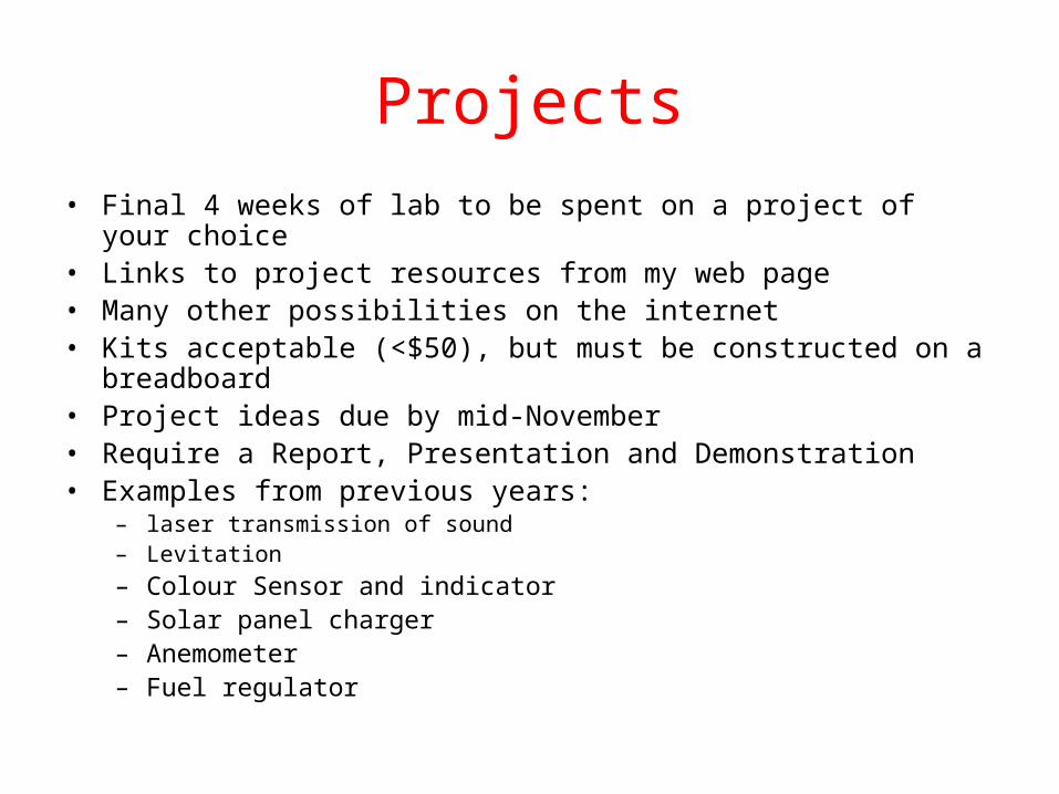
Projects• Final 4 weeks of lab to be spent on a project of your choice• Links to project resources from my web page• Many other possibilities on the internet• Kits acceptable (<$50), but must be constructed on a breadboard• Project ideas due by mid-November• Require a Report, Presentation and Demonstration• Examples from previous years:
– laser transmission of sound– Levitation
– Colour Sensor and indicator– Solar panel charger– Anemometer– Fuel regulator
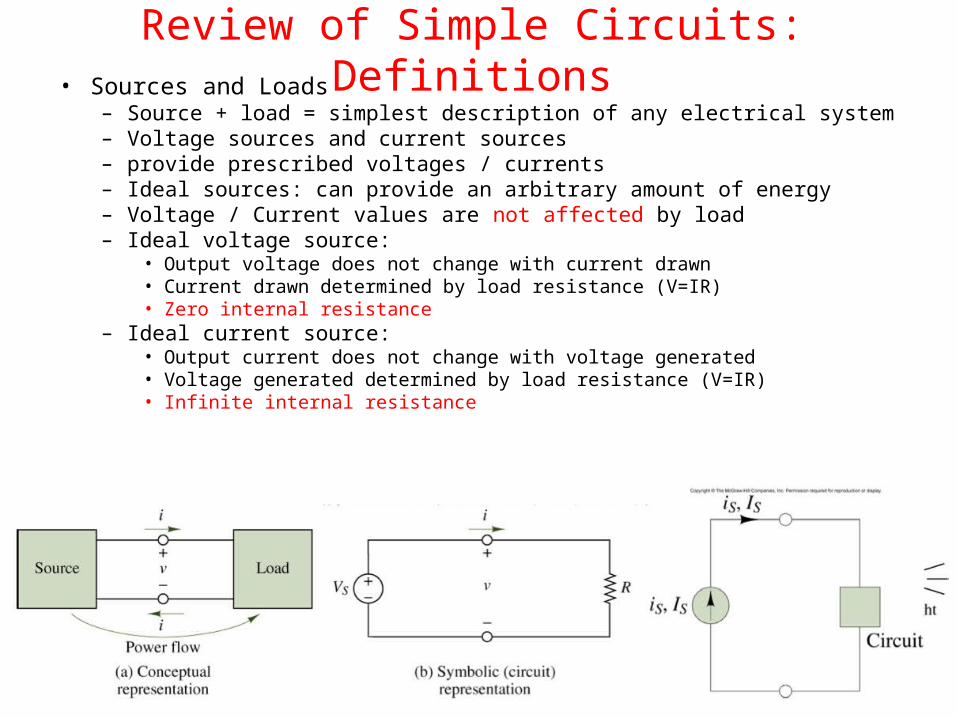
Review of Simple Circuits: Definitions• Sources and Loads
– Source + load = simplest description of any electrical system– Voltage sources and current sources – provide prescribed voltages / currents– Ideal sources: can provide an arbitrary amount of energy– Voltage / Current values are not affected by load– Ideal voltage source:
• Output voltage does not change with current drawn• Current drawn determined by load resistance (V=IR)• Zero internal resistance
– Ideal current source:• Output current does not change with voltage generated• Voltage generated determined by load resistance (V=IR)• Infinite internal resistance
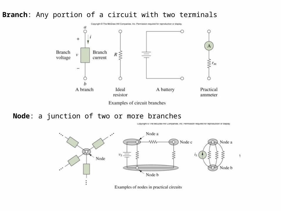
Branch: Any portion of a circuit with two terminals
Node: a junction of two or more branches
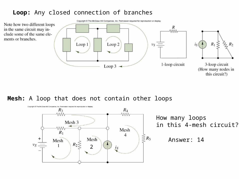
Loop: Any closed connection of branches
Mesh: A loop that does not contain other loops
How many loopsin this 4-mesh circuit?
2Answer: 14
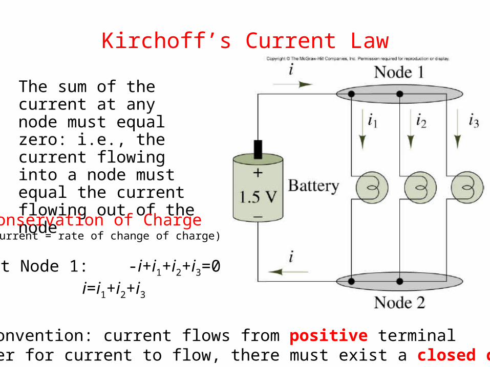
Kirchoff’s Current Law
The sum of the current at any node must equal zero: i.e., the current flowing into a node must equal the current flowing out of the node
At Node 1: -i+i1+i2+i3=0 i=i1+i2+i3
Conservation of Charge(Current = rate of change of charge)
Note convention: current flows from positive terminalIn order for current to flow, there must exist a closed circuit
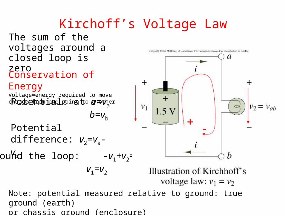
Kirchoff’s Voltage LawThe sum of the voltages around a closed loop is zero
Around the loop: -v1+v2=0 v1=v2
Conservation of EnergyVoltage=energy required to move charge from one point to another
Potential: at a=va
b=vb
Potential difference: v2=va-vb
Note: potential measured relative to ground: true ground (earth)or chassis ground (enclosure)