photofact* folder philco chassis 1ol41, - rsp … schematics/philco/philco_h3410...cated between the...
TRANSCRIPT

PHOTOFACT* Folderwith ClRCUITRACE*
PHILCO CHASSIS 1OL41,U, 1OL42, U, 1OL43, U
MODEL H3412L(Ch. 10L43)
TRADE NAME Philco MODELS CHASSIS
MANUFACTURERTYPE SETTUBESPOWER SUPPLYTUNING RANGE
H4254S, SL, H4674, L, W, H4676S, SL, H4678, W, H4680, L, W,H4682S, SL, SW, H4690, P, H4692W, H4696S, SW 10L41H4676SLR, SR, H4680LR, R, WR, H4690PR, R,H4692WR, H4698PE, R 10L42H3408C, H3410, L, V, H3412GL, L, H4432, L, H4730, W 10L43UH4254S, SL, UH4674, L, W, UH4676S, SL, UH4678, W, UH4680, L, W,UH4682S, SL, SW, UH4690, P, UH4692W, UH4696S, SW 10L41UUH4690PR, R, UH4698PR, R 10L42UUH3408C, UH3410, L, V, UH3412GL, L, UH4432, L, UH4730, W 10L43U
Philco Corp., Tioga & "C" Streets, Philadelphia, Pa.Television ReceiverVHF-Sixteen, UHF-Seventeea105-120 Volts AC, 60 Cycle RATING 160 Watts, 1. 7 Amp. ® 117 Volts ACChannels 2 thru 13 VHF, 14 thru 83 UHF, Video IF 45. 75MC, Sound IF 41. 25MC (Intercarrier)
SERVICING IN THE FIELD
SAFETY GLASS REMOVAL
Remove 2 screws at bottom of picture tube holding trim.Remove spring holding trim strip around picture tube. Re-move 2 screws holding metal shell strap. Remove strap andfront glass.
FUSE
A fuse wire is used for filament protection. (For location,see M4 in photo "Chassis Top View".)
FUSE DEVICE
A 5.6fi fusible resistor is used for low voltage power sup-ply protection. (For location, see "Tube Placement Chart'.')
TUNER OSCILLATOR ADJUSTMENTS
To touch-up the VHF Oscillator, remove Channel Selectorand Fine Tuning knobs.
AGC
The AGC may be varied by means of a Range Switch. (For
location, see "Tube Placement Chart".)
FOCUS
The focus may be varied by connecting the lead from pin 4of the picture tube to various voltage points. (For location,see photo "Chassis-Top View".)
HORIZONTAL OSCILLATOR FIELD ADJUSTMENTS
Coarse adjustment of the Horizontal Hold is accomplishedby the proper setting of the Horizontal Frequency control.(For location, see "Tube Placement Chart".)
WIDTH
The width may be varied by adjusting a metallic sleeve, lo-cated between the yoke and the picture tube neck, in or outof the yoke.
CENTERING
Centering is accomplished by 2 magnetic rings, located be-hind the yoke, on the neck of the picture tube.
K> O> IC >
cfi
HOWARD W. SAMS A CO., INC. Indianapolis 6, Indiana
The listing of any available replacement part herein doesnot constitute in any case a recommendation, warranty orguaranty by Howard W. Sams & Co., Inc., as to the qualityand suitability of such replacement part. The numbers ofthese parts have been compiled from information furnishedto Howard W. Sams & Co., Inc., by the manufacturers ofJA644
the particular type of replacement part listed. Repro-duction or use, without express permission, of editorial orpictorial content, in any manner, is prohibited. No patentliability is assumed with respect to the use of the informa-tion contained herein. © 1959 Howard W. Sams & Co., Inc. ,Indianapolis 6, Indiana. Printed in U.S. of America
DATE 12-59 SET 4 6 6 FOLDER 1

SOUND IF6EA8
AUDIO OUTPUT@ 6BQ5
TO TUNERANTENNA TERMINALS
THIS SWITCH MUST BECLOSED FOR ALL CLOCKSWITCH POSITION
SW ON e
VOLUME /«.CONTROL (ry
Y
TUNER 76-10524-3, -4, -5(T-100A, D. EKVHF) 5TUNER 76-10526-2, -11T-28C, D> 5REMOTE CONTROL RC-50 14TUNER 76-10525-3, -4, -5IT-101, A, 0, E) IVHF withUHFProvisionsI 16POWERTUNING 18
^DENOTES CHASSIS GROUND
» MEASURED FROM PIN 7 OF V2.
NUMBERS ASSIGNED TO COILS, SWITCHES, PLUGS, SOCKETS, ANDTRANSFORMERS ARE TO FACILITATE CIRCUIT TRACING OR COM-PONENT REPLACEMENT AND MAY NOT NECESSARILY BE FOUND ON
THE UNIT.
DC COIL RESISTANCE VALUES UNDER ONE OHMNOT SHOWN ON SCHEMATIC DIAGRAM
ARROWS ON CONTROLS INDICATE CLOCKWISE ROTATION(CONTROL VIEWED FROM SHAFT END)
WAVEFORMS TAKEN WITH CONTROLSSET TO PRODUCE 50 VOLTS PEAK-TO-PEAK SIGNAL AT PICTURE TUBE.
1. DC voltage measurements taken with vacuum tube 3. Mvoltmeter; AC voltage measured at 1000 ohms urper volt.
4. Line Voltag2. Pin numbi junted in clock
3rd W. Sams 8, Co., Inc. 1959
PAGE 2
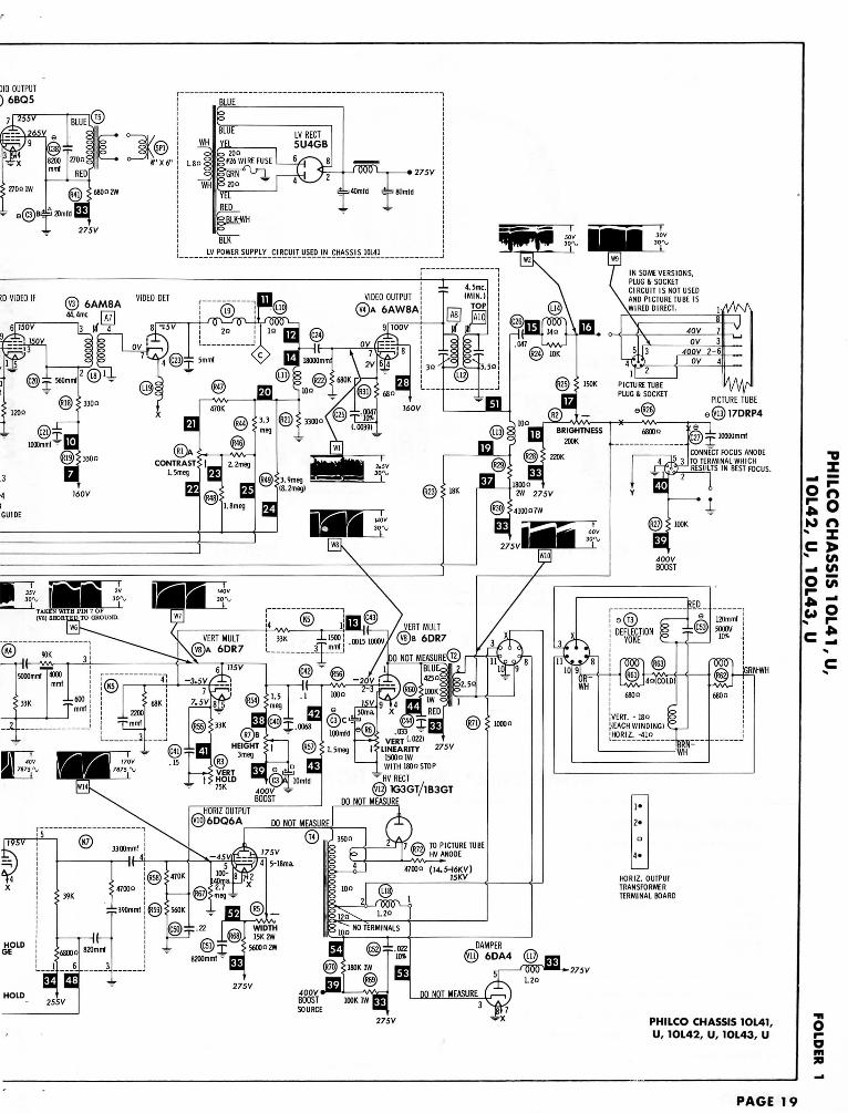
)IO OOTPUT) 6BQ5
PICTURE TUBE
elfl3)l7DRP4
CONNECT FOCUS ANODE
RESULTS IN BEST FOCUS.
N SOME VERSIONS,PLUG & SOCKETCIRCUIT IS NOT USEDAND PICTURETUBEISWIRED DIRECT. 1/W\
VIDEO OUTPUT
©A 6AW8A
©A
CONTRAST^ t J 2.2mec1.5rr
_-(VB) SHORTED TO GROUND.
A 6DR7 ! ™
1500° 1WWITH ISOnSTOP
VERTHOLD
75K 400VBOOST
* HV RECT
X33GT/1B3G1DO NOT MEASURE
HORIZ OUTPU1
10)6DO6A DO NOT MEASURE
, TO PICTURE TUBE' HV ANODE
47000 (I4.5-16KV]15KV
iRN-WH
•275V
27.5V PHILCO CHASSIS 1OL41,
U, 1OL42, U, 1OL43, U
PAGE 19
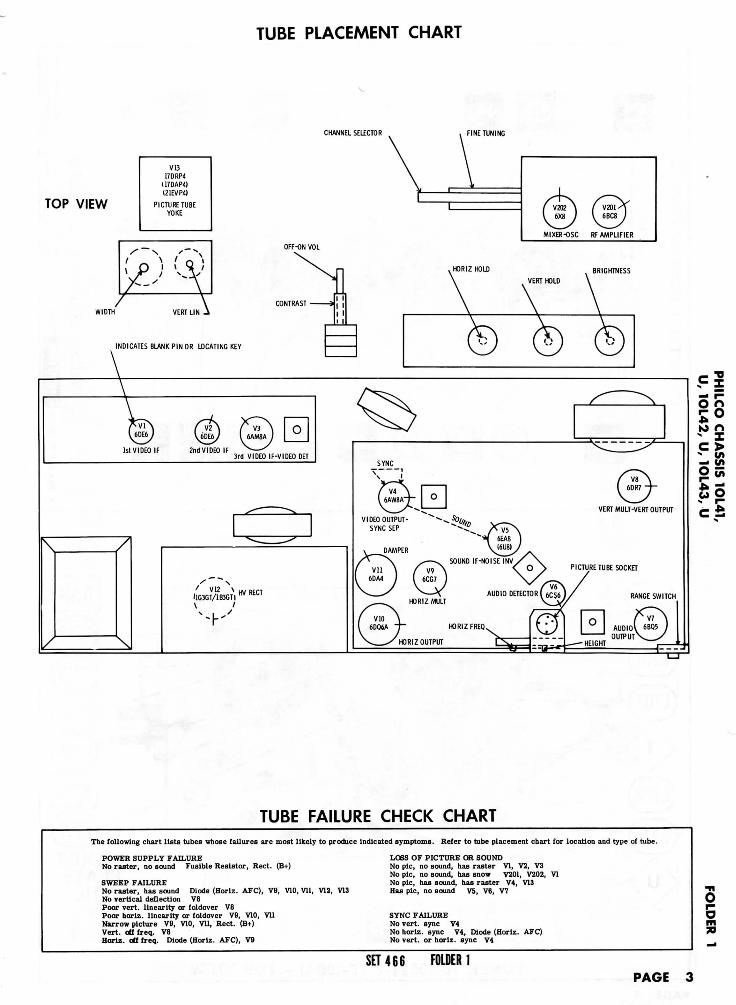
TUBE PLACEMENT CHART
CHANNEL SELECTOR
TOP VIEW
V1317DRP4
I17DAP4)(21EVP4I
PICTURE TUBEYOKE
MIXER-OSC RF AMPLIFIER
OFF-ON VOL
AINDICATES BLANK PIN OR LOCATING KEY
.HORIZ HOLD
3rd VIDEO IF-VIDEO DET
' V12 \I1G3GT/1B3GTI
>a
VERT MULT-VERT OUTPUT
PICTURE TUBE SOCKET
AUDIO DETECTOR 6C56J/ RANGE SWITCH
HORIZ FREQ
TUBE FAILURE CHECK CHART
The following chart lists tubes whose failures are most likely to produce indicated symptoms. Refer to tube placement chart for location and type of tube.
POWER SUPPLY FAILURENo raster, no sound Fusible Resistor, Rect. (B+)
SWEEP FAILURENo raster, has sound Diode (Horlz. AFC), V9, V10, Vll, TO, V13No vertical deflection V8Poor vert, linearity or foldover V8Poor horlz. linearity or foldover V9, V10, VllNarrow picture V9, V10, Vll, Rect. (B+)Vert. oUfreq. V8Horlz. ofl freq. Diode (Horiz. AFC), V9
LOSS OF PICTURE OR SOUNDNo pic, no sound, has raster VI, V2, V3No pic, no sound, has snow V201, V202, VINo pic, has sound, has raster V4, V13Has pic, no sound V5, V6, V7
SYNC FAILURENo vert, sync V4No horiz. sync V4, Diode (Horiz. AFC)No vert, or horiz. sync V4
5
SET 466 FOLDER 1PAGE 3
Ha2!
OiI
»— <oenCO
CO
oo
HOhj
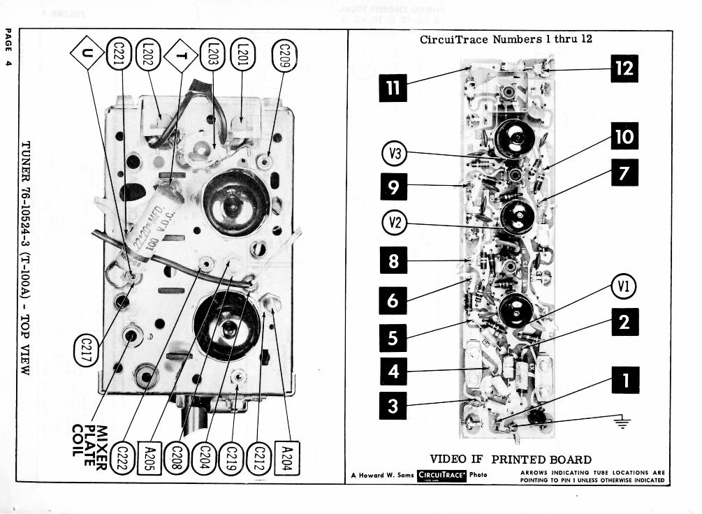
CircuiTrace Numbers 1 thru 12
VIDEO IF PRINTED BOARDA Howard W. Sam« Photo A R R O W S INDICATING TUBE LOCATIONS ARE
POINTING TO PIN 1 UNLESS OTHERWISE INDICATED

RF AMP® , , RF AMI(S) (S) 6BC8
Smmf 5* \^MIXER PLATE COIL
|(—@ JF OUTPUT
ICHANNEL SELECTOR SWITCH SHOWN IN CHANNEL 13 POSITION
•oX
gSSoK> n
N Ic >> w»_i (/»O t/5E i
A PHOTOFACT STANDARD NOTATION SCHEMATIC© Howard w. soms & Co., inc. ,959 VHF TUNER 76-10524-3. -4, -5 (T-100A, D, E)
UHF IF OUTPUT
<£|—o •—o »
S>j—o •—o
UHF ANT TERMINALBOARD
A PHOTOFACT STANDARD NOTATION SCHEMATIC© Howard W. Sams 8, Co., Inc. ,959 UHF TUNER 76-10526-2, -3 (T-28C, D)
oi-om70
SET 466 FOLDER I PAGE 5
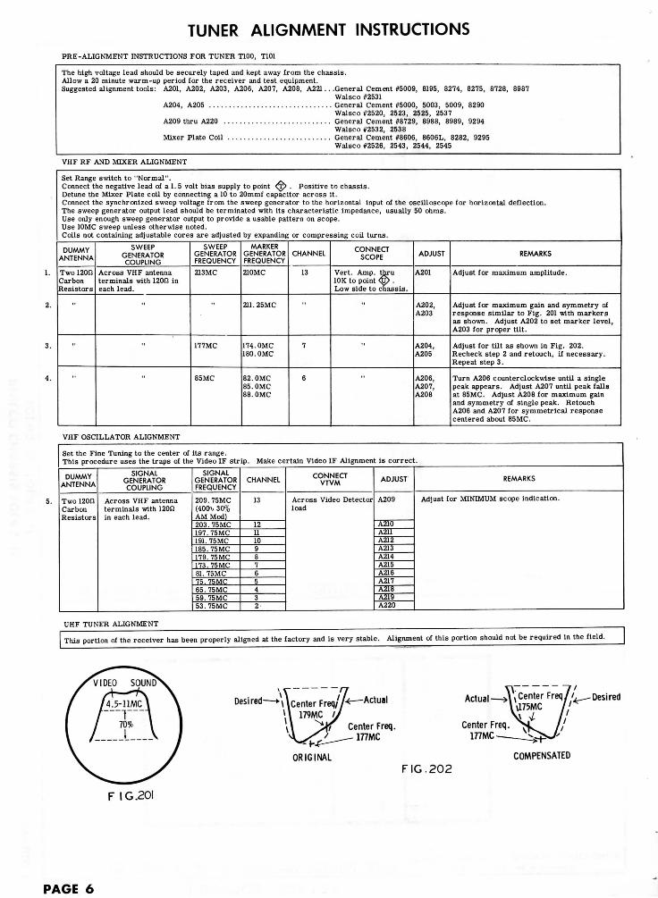
TUNER ALIGNMENT INSTRUCTIONSPRE-ALIGNMENT INSTRUCTIONS FOR TUNER T100, T101
The high voltage lead should be securely taped and kept away from the chassis.Allow a 20 minute warm-up period for the receiver and test equipment.Suggested alignment tools: A201, A202, A203, A206, A207, A208, A221 . . .General Cement #5009, 8195, 8274, 8275, 8728, 8987
Walsco #2531A204, A205 General Cement #5000, 5003, 5009, 8290
Walsco #2520, 2523, 2525, 2537A209 thru A220 General Cement #8729, 8988, 8989, 9294
Walsco #2532, 2538Mixer Plate Coil General Cement #8606, 8606L, 8282, 9295
Walsco #2526, 2543, 2544, 2545
VHF RF AND MIXER ALIGNMENT
Set Range switch to "Normal".Connect the negative lead of a 1. 5 volt bias supply to point <^> . Positive to chassis.Detune the Mixer Plate coil by connecting a 10 to 20mmf capacitor across it.Connect the synchronized sweep voltage from the sweep generator to the horizontal input of the oscilloscope for horizontal deflection.The sweep generator output lead should be terminated with its characteristic impedance, usually 50 ohms.Use only enough sweep generator output to provide a usable pattern on scope.Use 10MC sweep unless otherwise noted.Coils not containing adjustable cores are adjusted by expanding or compressing coil turns.
DUMMYANTENNA
Two 120SJCarbonResistors
"
SWEEPGENERATORCOUPLING
Across VHF antennaterminals with 120SJ ineach lead.
SWEEPGENERATORFREQUENCY
213MC
177MC
85MC
MARKERGENERATORFREQUENCY
210MC
211. 25MC
174. OMC180. OMC
82.0MC85. OMC88. OMC
CHANNEL
13
7
6
CONNECTSCOPE
Vert. Amp. thru10K to point <S> •Low side to chassis.
"
ADJUST
A201
A202,A203
A204,A205
A206,A207,A208
REMARKS
Adjust for maximum amplitude.
Adjust for maximum gain and symmetry ofresponse similar to Fig. 201 with markersas shown. Adjust A202 to set marker level,A203 for proper tilt.
Adjust for tilt as shown in Fig. 202.Reeheck step 2 and retouch, if necessary.Repeat step 3.
Turn A206 counterclockwise until a singlepeak appears. Adjust A207 until peak fallsat 85MC. Adjust A208 for maximum gainand symmetry of single peak. RetouchA206 and A207 for symmetrical responsecentered about 85MC.
VHF OSCILLATOR ALIGNMENT
Set the Fine Tuning to the center of its range.This procedure uses the traps of the Video IF strip. Make certain Video IF Alignment is correct.
DUMMYANTENNA
Two 120IJCarbonResistors
SIGNALGENERATORCOUPLING
Across VHF antennaterminals with 120nin each lead.
SIGNALGENERATORFREQUENCY
209. 75MC(400% 30%AM Mod)203. 75MC197.75MC191. 75MC185. 75MC179. 75MC173.75MC81. 75MC75.75MC65.75MC59. 75MC53.75MC
CHANNEL
13
12111098765432
CONNECTVTVM
Across Video Detectorload
ADJUST
A209
A210A211A212A213A214A215A216A217A218A219A220
REMARKS
Adjust for MINIMUM scope indication.
UHF TUNER ALIGNMENT
This portion of the receiver has been properly aligned at the factory and is very stable. Alignment of this portion should not be required in the field.
Desired—>\Venter Freq// Actual
Center Freq.177MC
Actualr\ /
,Center Freq/./^.Desired
Center Freq.177MC
ORIGINAL
FIG.202
COMPENSATED
F IG.20I
PAGE 6

TUNER PARTS LIST AND DESCRIPTIONS76-10524-3(T-100A)
TUBES
ITEMNo.
V201
CBS - GENERAL ELECTRIC - RAYTHEON - SYLVANIA
USE
RF Amplifier
TYPE
6BC8
ITEMNo.
V202
USE
Mixer-Osc.
TYPE
6X8
FIXED CAPACITORSCapacity values given in the rating column are in mfd. for Paper
Capacitors, and in mmfd. for Mica and Ceramic Capacitors.
ITEMNo.
C201C202C203C204C205C206C207C208C209C210C2UC212C213C214C215C216C217C218C219C220C2210222
RATING
39 NPO 10%5 ±. 25mmf5 ±. 25mmf5 10%10003 10%150.8-380 5%2.239 10%.8-37. 5 ±. 5mml100068015027 N220 10%3.9 10%27 N750 10%1 i.lmraf10001000
REMARKS
#30-1268-1
#30-1268-13
#30-1268-6130-1271-3
#30-1268-1
REPLACEMENT DATA
AEROVOXPART No.
NPO-DI 39NPO-SI 5NPO-SI 5
EF-001NPO-SI 3DI-150
NPO-SI 2. 2NPO-DI 39
BPD-001SI 680
NPO-SI 1EF-001EF-001
CENTRAIABPART No.
TCZ-39TCZ-4R7TCZ-4H7
MFT-1000TCZ-3R3DD-15I829-3
TCZ-2R2TCZ-39829-3
DD-102DD-681
TCZ-1MFT-1000MFT-1000
CORNEli-DUBILIERPART No.
C10Q39CC10V5CC10V5C
C10V3CL10T15
C10V22CC10Q39C
C10V8CBYA10D1BYA10T68
C10V4C
ELMENCOPART No.
CCTO-390CCTO-050CCTO-050
CCF-102CCTO-3R3CCD-151CV-1
CCTO-2R2CCTO-390CV-1
CCD-102CCD-681
*
CCTN-270
CCF-102CCF-102
MALLORYPART No.
CNO-439CNO-547CNO-547
CT280ACNO-533GP315CT565
CNO-522CNO-439CT565GP580GP210GPS 68
CNO-510CT280ACT280A
SPRAGUEPART No.
10TCC-Q3910TCC-V5010TCC-V50
10TCC-V3310TS-T15
10TCC-V2210TCC-Q39
5HK-D1010TS-T68
10TCR-Q2710TCC-V39
10TCC-V10
* Not normally In distributor's stock. Available thru distributor on order to manufacturer.I Phllco Part Number.
RESISTORSAll wattages 1/2 watt, or less, unless otherwise listed.
ITEMNo.
R20IR202R203R204
RATING
1500S210K1800SJ 1W10K
REMARKS ITEMNo.
R205J206*2071208
RATING
470K 5%470K 5%220K47K 1W
REMARKS
Note 1. Alternate 56K resistor is used in T-IOOA tuner.Ch. 10L42.
ITEMNo.
R209R210R211
RATING
15K10K68K 1W
REMARKS
Note 1
<=5— r-
O
K> n
cfi
COILS (RF-IF)
ITEMNo.
L201L202L203L204
L205L206
USE
Ant. CoilAnt. CoilIF TrapAnt. Coils
RF ChokeRF Coils
PHILCO
PART No.
32-4725-432-4725-432-4719-276-11498
32-4652-5276-11712
NOTES
Channel 2-13,Includes WaferAssy.
Channel 2-13,Includes WaferAssy.
ITEMNo.
L207
L208
L209
USE
Mixer GridCoils
Osc. Colls
Mixer Plate Coil
PHILCO
PART No.
76-10556
76-10108
32-4652-48
NOTES
Channel 2-13,Includes WaferAssy.Channel 2-13,Includes WaferAssy.
MISCELLANEOUSITEMNo. PART NAME
Switch ShaftWrench ExtensionShaftPre-Set Plate &Screw Assembly
PHILCO
PART No.
76-11451-1128-13074-1
76-11735-1
NOTES
AssemblyPart of Pre-Set Fine Tuning Assembly
Part of Pre-Set Fine Tuning Assembly
SET 466 FOLDERPAGE 7
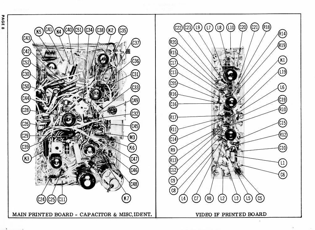
MAIN PRINTED BOARD - CAPACITOR & MISC.IDENT. VIDEO IF PRINTED BOARD
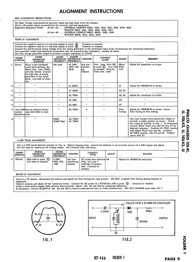
ALIGNMENT INSTRUCTIONSPRE-ALIGNMENT INSTRUCTIONS
The High Voltage lead should be securely taped and kept away from the chassis.Allow a 20 minute warm-up period for the receiver and test equipment.Suggested Alignment Tools: Al thru A4.
Al thru All .
.. GENERAL CEMENT #5000, 5003, 5014, 5015, 5016, 8276, 8290WALSCO #2512, 2515, 2522, 2523, 2525, 2537
. . GENERAL CEMENT #8606, 8606L, 8282, 9295WALSCO #2526, 2543, 2544, 2545
VIDEO IF ALIGNMENT
Connect the negative lead of a 6 volt bias supply to point <$> . Positive to chassis.Connect the negative lead of a 3 volt bias supply to point <$p . Positive to chassis.Connect the synchronized sweep voltage from the sweep generator to the horizontal input of the oscilloscope for horizontal deflection.The generator output lead should be terminated with its characteristic impedance, usually 50 ohms.Use only enough generator output to provide a usable indication on VTVM.
DUMMYANTENNA
Direct
"
"
"
"
Two 120S1CarbonResistors
SWEEPGENERATORCOUPLING
Place a thin insulatedmetal strip between theMixer -Osc. tube (V202),and tube shield. Connectthe high side of sweepgenerator to the metalstrip. Low side to chas-sis.
"
"
Across antenna termi-nals with 120SZ in eachlead.
SWEEPGENERATORFREQUENCY
Not used
"
"
"
"
69MC(10MC Swp)
MARKERGENERATORFREQUENCY
45. SMC(400-1. AMMod)
41. 25MC
47.25MC
42. 75MC
45.0MC
44.4MC
65.75MC
42. 75MC45. 75MC
CHANNEL
Any non-interfer-ingchannel
"
"
"
"
4
CONNECTSCOPE
Vert. Amp. thru 10Kto point <^> . Low sid<to chassis. (AcrossVideo Det. load)
"
"
"
"
ADJUST
MixerPlateCoil
Al
A2, A3
A4, A5
A6
A7
FineTuning
REMARKS
Adjust for maximum on scope.
Adjust for MINIMUM on scope.
"
Adjust for maximum on scope.
"
Adjust for MINIMUM on scope. LeaveFine Tuning at this setting.
Use only enough sweep generator output toprovide a usable pattern on scope. Checkfor response similar to Fig. 1. If necessaryretouch Mixer Plate Coil and A4 thru A7 fordesired response. Position 45. 75MC markeiwith Mixer Plate Coil and A6. Position42. 75MC marker with A4 and AS. Flattencurve with A7.
nI>
cfi
4. SMC TRAP ALIGNMENT
Use a 4. SMC tuned detector similar to Fig. 2. Before aligning trap, connect the detector to an accurate source of 4. SMC signal and adjustthe coil slug for maximum DC voltage output. Set Contrast fully clockwise.
DUMMYANTENNA
. OOlmfd
SIGNALGENERATORCOUPLING
High side to point ^ .Low side to chassis.
SIGNALGENERATORFREQUENCY
4. SMC(4001. 30%AM)
CHANNEL
Any non-interferingchannel
CONNECTVTVM
DC probe thru detectoi(Fig. 2) to pin 7(cathode) of picturetube. Common tochassis.
ADJUST
A8
REMARKS
Adjust for MINIMUM deflection.
SOUND IF ALIGNMENT
Tune in a TV station, disconnect the antenna and adjust the Fine Tuning for best picture. DO NOT readjust Fine Tuning during balance ofalignment.Connect antenna and adjust A9 for maximum sound. Connect the DC probe of a VTVM thru 10K to point <^> . Common to chassis.Using a weak station signal (with antenna disconnected), adjust A10, All and A12 for maximum deflection.If necessary, retouch SLIGHTLY AID, All and A12 to remove intercarrier buzz or noise interference. (DO NOT CHANGE more than 1/4".}
INPUT
PHILCO PART#32-4449 OR EQUIVALENT
OUTPUT
F I G . 1 F IG .2• i
O
1SET 4 6 6 FOLDER1 PAGE 9
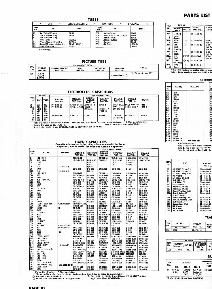
PARTS LISTTUBES
ITEMNo.
VIV2V3
V4V5V6
CBS • GENERAL ELECTRIC « RAYTHEON • SYLVANIA
USE
1st Video IF Amp.2nd Video IF Amp.3rd Video IF Amp.-Video Det.Video Output-Sync Sep.Sound IF Amp. -Noise Inv.Audio Detector
TYPE
6DE66DE6
6AM8A6AW8A6EA8 (6U8) *6CS6
ITEMNo.
V7V8V9V10VllV12
USE
Audio OutputVert. Mult. -Vert. OutputHoriz. Mult.Horiz. OutputDamperHV Reel.
TYPE
6BQ56DR76CC76DQ6A6DA41G3GT/IB3GT
PICTURE TUBE
ELECTROLYTIC CAPACITORS
> Not normally in distributor's stock. Available thru distributor on order to manufacturer.Note 1. Not used in Ch. 10L41, U. Note 3. Alternate Part *30-2590-56.Note 2. Ch. 10L41, U use 80/20/20/40mfd @ 350V (Part #30-2590-48).
FIXED CAPACITORSCapacity values given in the rating column are in mfd. for Paper
Capacitors, and in mmfd. for Mica and Ceramic Capacitors.
# Philco Part Number. * Alternate value.** Not normally in distributor's stock. Available thru distributor on order to manufacturer.
(Jl Not used in some versions. ® Ch. 10L41, U, 10L42, U use 135mmf 5% ® 5000V in this(2> Runs 1 thru 3 use 6800mraJf in this application. application (Part #30-1246-17).
ITEMNo.
V13
REPLACEMENT DATA
PHILCOPAST No.
17DRP417DAP421EVP4
GENERA1 ELECTRICPART No.
RCAPART No.
RAYTHEONPART No.
SYLVANIAPART No.
17DAP4/SF-17(D
NOTES
Q) "Silver Screen 85"
ITEMNo.
R1ABC
R2AB
R3ABC
H4AB
R5AB
ReR7A
B
RATING
RESIST-ANCE
1. 5megImeg*nVKh200KShaft75KShaftBushing50KShaft15KShaft1500SJ
leon stop100 K3meg
WAns1~
ii
i2(WW)
1(WW)
11
PHILCOPART No.
33-5592-49
33-5593-24
33-5593-25
33-5593-30
33-5574-7
33-5591-20
33-5595-3
CENTRPART
B-46Not ReB-35Not BeNot HeB-31Not ReWW-15Not Re
ITEMNo.
ClC2A
BCD
C3ABC
RATING
CAP.
200.80.200.2020•10.20100
VOLT.
15030015030030045035050
REPLACEMENT DATA
PHILCOPART No.
30-2568-7830-2590-52
30-2590-49
AEROVOXPART No.
AFHS1-24-24!AFHS4-47-25
AFH3-157
CORNELL-DUBILIER
PART No.XA0262. 1 S
/D0022\BB20015
aiso
MALLORYPART No.
FP118 §
rFP333.8I-WS342
FP389
PYRAMIDPART No.
TMS-26 5TMT-43 1TD-200-150,
TMD-49TD-100-50
SPRAGUEPART No.
TVLS-1431. !•§TVLS-4576 •
TVL-3928
NOTES
Note 1Note 2
Note 3
ITEMNo.
C4C5C6C7C8C9aoCllC12CISC14C15C16C17CISC19C20C21C22C23C24C25C26C27C28C29C30C31C32C33C34C35C36C37C38C39C40C41C42C43C44C45C46C47C48C49C50C51C52C53C54C55
RATING
.22 100V3.3 NPO.5-3.5-31-510001-5. 22 100V68010003.3 NPO 10%4701000680. 1 200V100056010001000518000.0047 400V 10%.047 400V100008200.1 200V47004701000.1 200V150027 N3302200330082002200.0068 400V. 15 100V.1 400V.0015 1000V.033 400V3900.0039 600V 10%47 10%390 10%.01 400V. 22 100V8200.022 400V 10%120 5000V 10%.022 600V1000
REMARKS
1(31-6535-2
(31-6535-2
(. 0039mfd)»
0>
(30-1263-46(4700mmf)»
®
(. 022mfd)*
(30-1246-26(3
REPLACEMENT DATA
AEROVOXPART No.
P288N-22NPO-DI3.3
BPD-001
P288N-22BPD-00068BPD-001NPO-SI3.3BPD-00047BPD-001BPD-00068P288N-1BPD-001DI-560BPD-001BPD-001DI-5BPD-02V84C6D47-10?P488N-047BPD-01DAC-26P288N-1BPD-0047BPD-00047BPD-001P288N-1BPD-OOI5
BPD-0022BPD-0033DAC-26BPD-0022P488N-0068P288N-15P488N-1P1088N-0015P488N-033BPD-004V84C6D4-10%1469-0000471469-00039P488N-01P288N-22DAC-26V84C4S22-105!
F688N-022BPD-001
CENTRALABPART No.
DTZ-3R3829-3829-3829-6DD-102829-6
DD-681DD-102TCZ-3R3DD-471DD-102DD-681DF-104DD-102DD-561DD-102DD-102DD-050DD-203
DD-503DD-103DD-822DF-104DD-472DD-471DD-102DF-104DD-152
DD-222DD-332DD-822DD-222D6-682
DF-104DD-152DD-303DD-392
TCZ-47D6-391DD-103
DD-822DD-203
DD-203DD-102
CORNELL-DUBILIERPART No.
CUB2P22C10V33C
BYA10D1
CUB2P22BYA10T68BYA10D1C10V33CBYA10T47BYA10D1BYA10T68CUB2P1BYA10D1L10T56BYA10D1BYA10D1L10V5BYB6S2PM6D47CUB4S47BYA10S1HVE16D8CUB2P1BYA10D47MBYA10T47BYA10D1CUB2P1BYA10D15
BYA10D22BYA10D33HVE16D8BYA10D22CUB6D68CUB2P15CUB4P1COB10D15CUB4S33BYA10D4PM6D422H5Q4722R5T39CUB4S1CUB2P22HVE16D8PM4S22
CUB6S22BYA10D1
ELMENCOPART No.
1DP -3-224CCTO-3H3CV-1CV-1
CCD-102
1DP -3-224CCD-681CCD-102CCTO-3R3CCD-471CCD-102CCD-6812DP-3-104CCD-102CCD-561CCD-102CCD-102CCD-050CCD-2036DP-1-4724DP-3-473CCD-103CCD-8222DP-3-104CCD-472CCD-471CCD-1022DP-3-104CCD-152**CCD-222CCD-332CCD-822CCD-2226DP-1-6821DP-3-1544DP-3-10416DP-1-1524DP-2-333CCD-3926DP-1-392
CM-20B-470KCM-20B-391K4DP-1-1032DP-3-224CCD-8224DP-2-223
8DP-2-223CCD-102
MALLORYPART No.
GEM-2022CNO-522CT565CT565
B-210
GEM-2022B-368B-210CNO-522B-347B-210B-368GEM-201B-210B-356B-210B-210GP550B-120JL-247GEM-4147B-110B-282GEM-201B-247B-347B-210GEM-201B-215
B-222B-233B-282B-222GEM-6268GEM-2015GEM-401GEM-10215GEM-4133GP239GEM-1624MCB225MCB243GEM-4UGEM-201B-282GEM-1612
GEM-6122B-210
SPRAGUEPART No.
2TM-P2210TCC-V33
5HK-D10
2TM-P225GA-T685HK-D1010TCC-V335GA-T475HK-D105GA-T682TM-P15HK-D105GA-T565HK-D105HK-D1010TS-V505IIK-S206TM-D474TM-S475HK-S106TM-D82TM-P15HK-D475GA-T475HK-D102TM-P15HK-D15
5HK-D225HK-D336TM-D85HK-D226TM-D682TM-P154TM-P110TM-D154TM-S335HK-D406TM-D4MS-447MS-3394TM-S12TM-P226TM-D84TM-S22
6TM-S225HK-D10
' Use 180n resistor in series with tenNote 1. Some versions may use 1500O with
All wattages
ITEMNo.
R8R9RIORUR12R13R14R15R16R17R18R19R20H2IR22R23R24R25R26R27R28R29R30
RATING
22Kmoon27Klooon47O180K15Kmoon220K22K330SJ33012120B3300B680K18KIDE150K6 soon100K220K180011 2W4100SJ 7W
REMARKS
B3-1335-149
R3R3R3R3R3R3R3R3R4R4R4R4R4R4R4'R4R4R4R5iR5:R5R5:
* Alternate value-Note 1. Not used in some versions.Note 2. Run 4 and later use 5600n :Note 3. Not used in Ch. 10L41, U.
ITEMNo.
LIL2L3L4L5L6L7L8L9L10LllL12A
BL13L14L15L16LJ7LIBL19
USE
47. 25MC Trap Coll47. 25MCTrap Coll41. 25MC Trap CoilRF Choke1st Video IF Coil2nd Video IF3rd Video IF4th Video IFResonant ChoiceResonant ChokeShunt Peaking CoilSound Take-Off4. SMC TrapShunt Peaking CollSeries Peaking Coil2nd Sound IFQuadrature CoilRF ChokeRF ChokeFil. Choke
PHILCOPART No.
32-4645-3232-4645-1932-4645-3432-4645-4132-4645-3632-4686-2232-4686-232-4686-332-4674-132-4645-732-4762-832-4688-9
32-4762-832-4762-1032-4745-232-4644-2032-4112-6232-4112-6232-4645-40
TRAr
ITEMNo.
L20
DC RES.
PRI.150!)
SEC.
PHILCOPART No.
32-4754-3
HolldoPART
ITEMNo.
L21
RATINGS
CURRENT(Measured)
.310A
DC RES.
4m
INDUCTANCE(0 CURRENT
1000 'X.I
1.3 Hy.
PHPAI
32-8
TR>
ITEMNo.
Tl
RATING
PRI.117V®1. 7A
SEC. 1120V®
1.17A(AC)
SEC. 26.3V®SAtap®2.7VA®
PHIL(PART
32-8902
(J> Ch. 10L41, U use Part »32-8897-l.
PARE 1O
SYLVANIA
jtput
TYPE
6BQ56DR76CG76DQ6A6DA41G3GT/1B3GT
§ Use insulating tube.Part #30-2590-56.
PARTS LIST AND DESCRIPTIONSCONTROLS
IA
-17(8
NOTES
(J> "Silver Screen 85 "
ITEMNo.
H1ABC
R2AB
H3ABC
R4AB
R5AB
R6
R7AB
RATING
RESIST-ANCE
l.SmegImegAritch200KShaft75 KShaftBushing50KShaft15 KShaft1500(2
180(2 stop100K3 meg
WATTS
2i
i
i
i2(WW)
1(WW)
|
REPLACEMENT DATAPfflLCOPART No.
33-5592-49
33-5593-24
33-5593-25
33-5593-30
33-5574-7
33-5591-20
33-5595-3
CENTRALABPART No.
B-46Not Heq.B-35Not Req.Not Req.B-31Not Req.WW-153Not Req.
CLAROSTATPART No.
A47-200K-SFS-3A47-75K-SFS-3Not Req.A47-50K-SFS-3A58-15KFKS-1/439-1500 *
IRCPART No.
011-129Not Req.Qll-125Not Req.Not Req.011-123Not Req.WPK15000Not Req.112-1500 *
MA1LORYPART No.
* UE4069-S
U43Not Req.RU753LSS-3500SL38TA54LNot Req.R15MLNot Req.FL-15K*
INSTALLATION NOTES
ContrastVolumePush-Push Off -OnBrightness
Vert. Hold
Horiz. Hold
Width
Vert. Lin. , Note 1
Horiz. Freq.Height
• Use 180(2 resistor In series with terminal. . "STA-LOC" Equivalent: FA155L, RUP16L, DS1125Note 1. Some versions may use 1500(2 with 300(2 stop (Part #33-5591-17).
ITEMNo.
T2T3
T4
USE
Vert. OutputYoke-Horlz. (24MH)(110°)-Vert. (37MH)Alt. YokeAlt. YokeRear Cover, Clamp,& Centering Assy.Rear Cover, Clamp,& Centering Assy.Horiz. Output
PHILPART
32-882976-10501
76-1050176-1050176-11644
76-10513
32-8899
(J> Use 8 to 1 turns ratio. (i® Used in Ch. 10L41, U. (j® Used in Ch. 10L42, U.
TR
RESISTORSAll wattages 1/2 watt, or less, unless otherwise listed.
SPRAGUEPART No.
rVLS-1431.1'8TVLS-4576 «
TVL-3928
NOTES
Note 1Note 2
Note 3
ITEMNo.
R8R9RIORllR12R13R14HISR16R17R18H19R20R21R22R23R24R25R26R27R28R29R30
RATING
22K1000(227K1000(247(2180 K15K1000(2220K22K330(2330(2120(13300(2680 K18KIDE150K6800(2100K220K1800(2 2W4100O 7W
REMARKS
#33-1335-149* Alternate value.
ITEMNo.
R31R32R33R34R35R36R37R38R39R40R41R42R43R44R45R46R47R48R49R50R51R52R53
RATING
88n22K150(2470S21500(2180K6800(2 2W15 K270(2 5%100(2680(2 2W270S2 1W47K3.3meg12meg2. 2meg470 K1. 8meg3.9meg6800(24300(2 5%12meg22K 5% 1W
REMARKS
0>
(8. 2meg)»
»66-24382-40
I PhilcoPart Number.
ITEMNo.
R54R55R56R57R58R59R60R61R62R63R64R65R66R67R68R69R70R71R72H73R74H75R76
RATING
1. 5meg33K100(2l.Smeg470K560K100K 1W680(2680(24£2 Cold10K1W1000(256 K2. 7meg5600(2 2W100K 1W180K 1W1000(24700(2470K5.6(23000(2 7W390(2 1W
REMARKS
*33-1343-19
*66-2565340 @
133-1366-3 ®133-1363-36
MAUORYPART No.
GBM-2022CNO-522CT565CT565
B-210
GEM-2022B-368B-210CNO-522B-347B-210B-368GEM-201B-210B-356B-210B-210GP550B-120JL-247GEM-4147B-110B-282GEM-201B-247B-347B-210GEM-201B-215
B-222B-233B-282B-222GEM-6268GEM-2015GEM-401GEM-10215GEM-4133GP239GEM-1624MCB225MCB243GEM-411GEM-201B-282OEM-maGEM-6122B-210
SPRAGUEPART No.
2TM-P2210TCC-V33
5HK-DIO
2TM-P225GA-T685HK-D1010TCC-V335GA-T475HK-D105GA-T682TM-P15HK-D105GA-T565HK-D105HK-D1010TS-V505HK-S206TM-D474TM-S475HK-S106TM-D82TM-P15HK-D475GA-T475HK-D102TM-P15HK-D15
5HK-D225HK-D336TM-D85HK-D226TM-D682TM-P154TM-P110TM-D154TM-S335HK-D406TM-D4MS-447MS-3394TM-S12TM-P226TM-D84TM-S22
6TM-S225HK-D10
.Note 1. Not used in some versions.Note 2. Run 4 and later use 5600(2 3W in this application.Note 3. Not used in Ch. 10L41, U.
COILS (RF-IF)
ITEMNo.
LIL2L3L4L5L6L7L8L9L10LllL12A
BL13L14L15L16L17L18L19
USE
47. 25MC Trap Coil47. 25MC Trap Coil41. 25MC Trap CoilRF Choke1st Video IF Coll2nd Video IF3rd Video IF4th Video IFResonant ChokeResonant ChokeShunt Peaking CoilSound Take-Off4. SMC TrapShunt Peaking CoilSeries Peaking Coil2nd Sound IFQuadrature CollRF ChokeHF ChokeFil. Choke
REPLACEMENT DATA
PHILCOPART No.
32-4645-3232-4645-1932-4645-3432-464S-4132-4645-3632-4686-2232-4686-232-4686-332-4674-132-4645-732-4762-832-4688-9
32-4762-832-4762-1032-4745-232-4644-2032-4112-6232-4112-6232-4645-40
GromerPART No.
19-1001
19-3001
19-4201
19-420119-3330
19-100519-1005
MeissnerPART No.
19-1001
19-3001
19-4201
19-420119-3330
19-100519-1005
MeritPART No.
BC-562
TV-189
TV-197
TV-197TV-200
BC-566BC-566
MillerPART No.
4604
6175
6154
61546132
46124612
PART No.
VP-9
VP-7
NOTES
Includes C14
22uh3uh220uh
220uh330uh
9uh9uh
TRANSFORMER (HORIZ. OSC.)
ITEMNo.
L20
DC RES.
PRI.150(2
SEC.
REPLACEMENT DATA
PHILCOPART No.
32-4754-3
HolldorsonPART No.
MeritPART No.
MillerPART No. PART No.
ThordorsonPART No.
NOTES
Horiz. Stabilizer
FILTER CHOKE
ITEMNo.
L21
RATINGS
CURRENT(Measured)
.310A
DC RES.
41(2
INDUCTANCE(0 CURRENT
1000 'X.l
1.3 Hy.
REPLACEMENT DATA
PHILCOPART No.
32-8710-8
HolldorsonPART No.
26C44
MerilPART No. PART No.
SlancorPART No.
ThordarsonPART No.
26C44
TriodPART No.
C-28X
TRANSFORMER (POWER)
imi 5% ® 5000V in this
ITEMNo.
Tl
RATING
PRI.
117V ®1.7A
SEC. 1
120V®1.17A(AC)
SEC. 2
6.3V®8A tap®2.7VA®
REPLACEMENT DATA
PHILCOPART No.
32-8902-1 CD
HolldorsonPART No.
MeritPART No.
RomPART No.
StancorPART No. PART No.
TriadPART No.
ITEMNo.
T5
IMPEDANCE
PRI.
4300!!SEC.
3-4(2
PHILCOPART No.
32-8862-2
ITEMNo.
SP1
TYPE
SIZE
4" x 6"
FIELD
PM
V. C. IMP.
3-4(2
ITEMNo.
KlK2K3
K4
K5K6
K7
USE
2nd Video IF CathodeAudio Detector GridSync Sep. Grid
Vert. Integrator
Vert. FeedbackHoriz. AFC Network
Horiz. Mult. Network
ITEMNo.
MlM2M3
RATING
CURRENT(Measured)
.310 A
.310A
PHILCOPART No.
34-8048-1 3) ®34-8048-1 CIS34-8037 ®
ITEMNo.
M4
TYPE RATINGPHPAR
FUSE
2" Length »26 Wire
ITEMNo.
MS
M6
PART NAME
TunerTunerTunerTunerTunerTunerTunerTunerSwitchSwitchSwitchSwitchMagnetPrinted BoardPrinted BoardPrinted Board
PHILPART
76-10524-76-10525-76-10524-76-10525-76-10524-76-10525-76-10526-76-10526-42-2075-142-2117-176-11140-142-210876-1097054-699354-699454-6994-2
(J) Ch. 10L41, U use Part #32-8897-1.
High Voltage LeadShielded Hook-up Wire
General-use Unshielded Hook-up 1
Power Cord (Interlock Type).....300& Tuner Input Lead30012 Antenna Lead-inAntenna Rotor Cable

IPTIONSTRANSFORMERS (SWEEP CIRCUITS)
^0.
0
1
MALLORYPART No.
• UE4069-S
U43Not Reg..RU753LSS-3500SL38TA54LNot Req.R15MLNot Req.FL-15K •
INSTA1LATION NOTES
ContrastVolumePush-Push Ofl-OnBrightness
Vert. Hold
Horiz. Hold
Width
Vert. Lin. , Note 1
Horiz. Freq.Height
ITEMNo.
T2T3
T4
USE
Vert. OutputYoke-Horiz. (24MH)(110°)-Vert. (37MH)Alt. YokeAlt. YokeRear Cover, Clamp,& Centering Assy.Rear Cover, Clamp,Si Centering Assy.Horiz. Output
REPLACEMENT DATAPHILCOPART No.
32-8829-576-10508-14
76-10508-13(276-10508-16(176-11644-1 (3)
76-10513-2 ®
32-8899-1
HolldorsonPART No.
26S75 0>
MeritPART No.
RomPART No.
RogersPART No.
StoncorPART No.
ThordarsonPART No.
26S75 (J>
PART No.
A-108X
I Use 8 to 1 turns ratio.) Used in Ch. 10L41, U.) Used in Ch. 10L42, U.
"STA-LOC" Equivalent: FA155L, RUP16L, DSI125
icrwise listed.
) Used in Ch. employing 17DRP4 or 21EVP4 picture tube.) Used in Ch. employing 17DAP4 picture tube.
TRANSFORMER (AUDIO OUTPUT)
ITEMNo.
T5
IMPEDANCE
PRI.
4300SJSEC.
s-4n
REPLACEMENT DATAPHILCOPART No.
32-8862-2
HolldorsonPART No.
24S51
MeritPART No.
A-2930
RamPART No.
AU-601
PART No.
A-3877
ThordarsonPART No.
24S51
TriodPART No.
S-3X
NOTES
ITEMNo.
R54R55R56R57R58R59R60R61R62R63H64R65R66R67H68R69R70R7IR72R73R74H75R76
RATING
1. 5meg33 K100!!1. 5 meg470K560K100K 1W68017680Q4tJ Cold10K1Wlooon56K2. 7meg5600SJ 2W100K 1W180K1WlOOOi!4700S1470 K5.61!3000ii 7W390SJ 1W
REMARKS
»33-1343-19
*66-2565340 @
J33-1366-3 ®»33-1363-36
SPEAKER
ITEMNo.
SP1
TYPE
SIZE
4"x6 "
FIELD
PM
V. C. IMP.
3-4(2
REPLACEMENT DATA
PHILCOPART No.
36-1676-8
QUAMPART No.
46A1
NOTES
COMPONENT COMBINATIONS
ITEMNo.
raK2K3
K4
K5K6
K7
USE
2nd Video IF CathodeAudio Detector GridSync Sep. Grid
Vert. Integrator
Vert. FeedbackHoriz. AFC Network
Horiz. Mult. Network
DESCRIPTION
15mmf, 68ft150mmf, 1SK390mmf, 3300mm!, 220K, 330K,imeg, 1. 5megISOmmf, 600mmf, 4000mmf,SOOOmmf, 10 K, 33 K, 90 KISOOmmf, 2200mmf, 33K, 68K82mmf, 220mmf, lOOOmmi,50000mm!, 82K, 150K, 680K,1. 2meg390mml, 820mmf, 3300mmf,4700!i, 6800O, 39K
PHILCOPART No.
30-6039-130-6031-130-6532-3
30-6030-7
30-6509-130-6035-2
30-6531-2
REPLACEMENT DATA
Sprague PRC-12Sprague PRC-7
Sprague V-23
Sprague C-ll
DATA
MeritPART No.
BC-562
TV-189
TV-197
TV-197TV-200
BC-566BC-566
MillerPART No.
4604
6175
6154
61546132
46124612
PART No.
VP-9
VP-7
NOTES
Includes C14
22uh3uh220uh
220uh330uh
9uhBub
RECTIFIERSITEMNo.
MlM2MS
HATING
CURRENT(Measured)
.310A
.310A
REPLACEMENT DATA
PHILCOPART No.
34-8048-1 G> ®34-8048-1 (J) ®34-8037 3>
FEDERALPART No.
HF-504 ®HF-504 ®K1615 (3)
INTERNATIONALPART No.
SD-500 ®SD-500 ®SD-91 ® ®
SARKESTARZIANPART No.
40K@40K®
SYLVANIAPART No.
SR500 @SR500 ®
NOTES
CD Ch.IOMl use 5U4GBS Silicon type.
Dual Selenium Diode3) Two Required
>clO n
c >
S3
FUSES
ITEMNo.
M4
TYPE RATING
REPLACEMENT DATAPHILCOPART No.
FUSE
2" Length f26 Wire
HOLDER
LITTELFUSEPART No.
FUSE HOLDER
BUSSPART No.
FUSE HOLDER
MISCELLANEOUS
Z. OSC.)
PART No.ThordarsonPART No.
NOTES
Horiz. Stabilizer
VIENT DATA
0. PART No. PART No. PART No.
26C44
TriodPART No.
C-28X
ITEM
MS
M6
PART NAME
TunerTunerTunerTunerTunerTunerTunerTunerSwitchSwitchSwitchSwitchMagnetPrinted BoardPrinted BoardPrinted Board
PHILCOPART No.
76-10524-376-10525-476-10524-576-10525-376-10524-476-10525-576-10526-376-10526-242-2075-142-2117-176-11140-142-210876-1097054-699354-699454-6994-2
NOTES
VHF (T-100D) Ch. 10L43VHF (T-100E) Ch. IOL41VHF (T-100A) Ch. 10L42VHF with UHF provisions (T-101D) Ch. 10L43UVHF with UHF provisions (T-101E) Ch. 10L41UVHF with UHF provisions (T-10IA) Ch. IOL42UUHF (T-28D) Ch. 10L41U, 10L42UUHF (T-28C) Ch. 10L43URange (SPOT Slide Type)Manual-Remote, Ch. 10L42Touch Tuning, Pushbutton, Ch. 10L42Stepper, Remote TuningBeam Alignment , Used on some picture tubesVideo IFMain, Run 1Main, Run 2 (Red Dot)
WIRING DATA
WER)MENT DATA
PART No.Sloncor
PART No. PART No.Triod
PART No.
High Voltage Lead Use BELDEN No. 8869Shielded Hook-up Wire Use BELDEN No. 8885 (Single Conductor)
8738 (Two Conductor)General-use Unshielded Hook-up Wire Use BELDEN No. 8530 (Solid) Available in Ten Colors
8524 (Stranded) Available in Ten ColorsPower Cord (Interlock Type) Use BELDEN No. 8874300S2 Tuner Input Lead Use BELDEN No. 8225300O Antenna Lead-In Use BELDEN No. 8230 or 8275Antenna Rotor Cable Use BELDEN No. 8464 (Flat) or 8484 (Round) - 4 Conductor
8485 (Round) - 5 Conductor8488 (Round) - 8 Conductor
05
PAGE 11
PAGE 12
CHASSIS TOP VIEW

MAIN PRINTED BOARD - RESISTOR & INDUCTOR IDENTIFICATIONPAGE 13
1ST AMP6AU6
2ND AMP6AU6
LIMITER-TPJPLER
6CB6 PART132-4779-1
CHANNEL SELECTORRELAY CONTROL
6BJ8
>1.5meg
lOmlH iS I
PART (30-2590-51
VSA — '90K
3000nmf
Aa
<< l\.2mes
68K1W
ISOOOmml
29
PART 152-4778-1.
I,V J
<
SOOOmmf
PRE-AMP
6AU6
it5
2 /^PART
5^ »32-47_82-l68!
nrmml 5
iTl3 5
|
Imeg
;
29
k] 33mmf
TRANSDUCER iPARTH6-1686 S2.2meg
10*
-> 470K
•68K
; 10000- mmf ^
I I 2
"PREAMPLIFIEROSC
T1605PART <34-6001-25
CI-5.TV
CHANNEL SELECTORRELAYPART 142-4038-1
IBI-STABLE)PART»42-4039-1
330VSOUND RELAYIBI-STABLE]PART»42-1039-I
'BATTERY I5~4VI CHANNEL SELECTOR(40KC)
A PHOTOFACT STANDARD NOTATION SCHEMATIC
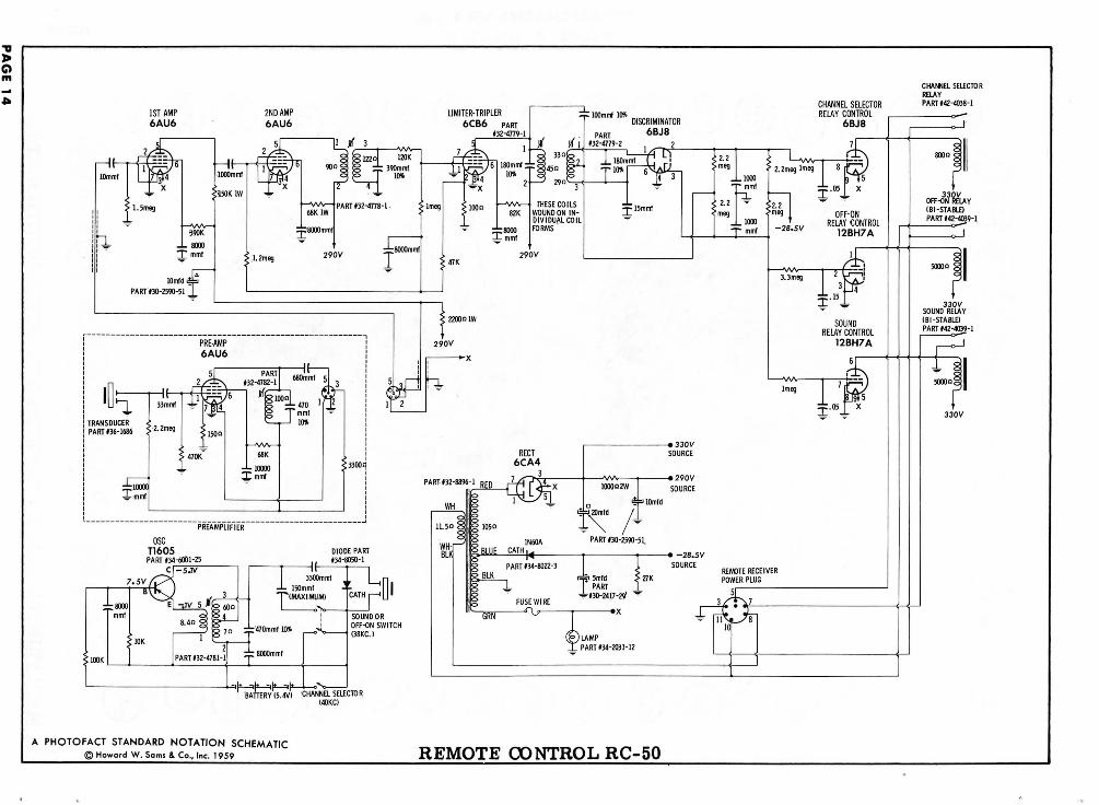
© Howard W. Sams & Co., Inc. 1959 REMOTE CONTROL RC-50

TUNER 76-10524-3 - LEFT SIDE
•oI
nI
c >"
O5
TUNER 76-10524-3 - RIGHT SIDEPAGE 15
5mmf f .25mmf
MIXER PLATE COIL
t
USED ONLY IN TUNERSWITH INDIVIDUAL FINE ionTUNING ~~-— ,-AA/V-
IF OUTPUT
UHF TUNER B-I- SOURCE
TO UHF DIAL LAMP
<-FILAMENTS
CHANNEL SELECTOR SWITCH SHOWN IN CHANNEL 13 POSITION
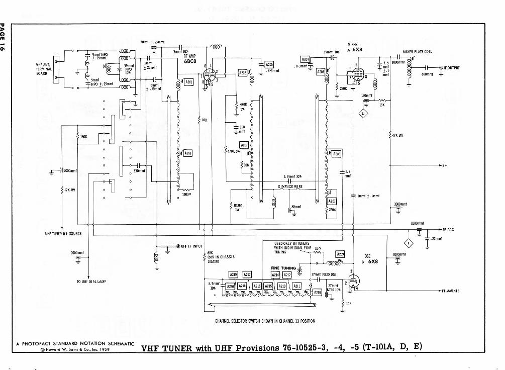
A PHOTOF£~™PtR° rc0":'°LSCHEMATIC VHF TUNER with UHF Provisions 76-10525-3, -4, -5 (T-101A, D, E)
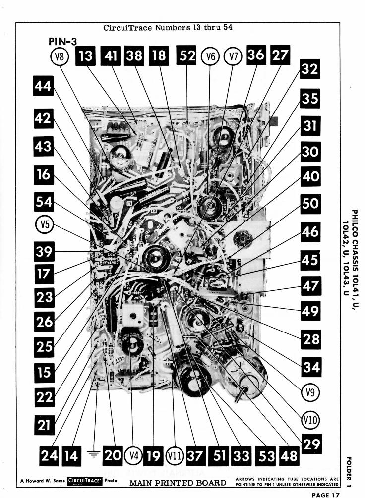
CircuiTrace Numbers 13 thru 54
PIN-3
A Howard W. Sami CIRCUITRACE* Photo MAIN PRINTED BOARDA R R O W S INDICATING TUBE LOCATIONS AREPOINTING TO PIN 1 UNLESS OTHERWISE INDICATED
•oX
K> O- IC >- t/>_• t/jO t/>
PAGE 17
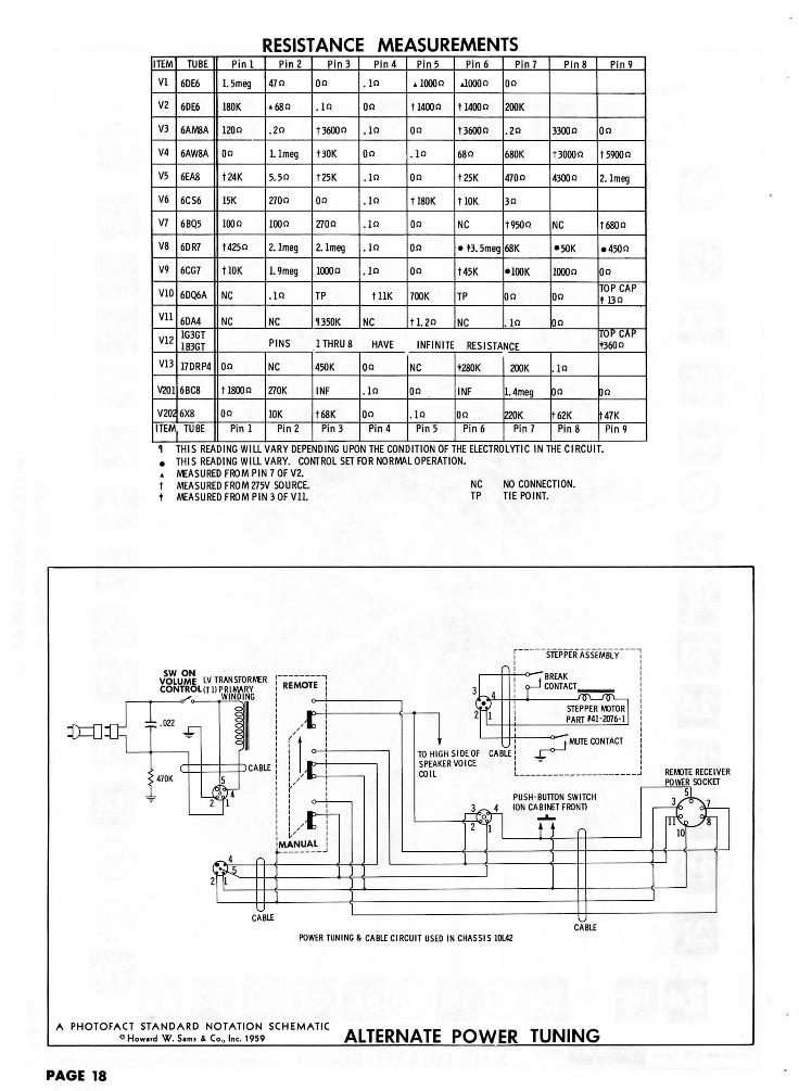
RESISTANCE MEASUREMENTSITEM
VI
V2
V3
V4
V5
V6
V7
V8
V9
V10
Vll
V12
V13
V201
V202
TUBE
6DE6
6DE6
6AM8A
6AW8A
6EA8
6CS6
6BQ5
6DR7
6CG7
6DQ6A
6DA41G3GT1B3GT
17DRP4
6BC8
6X8
ITEM TUBE
Pin!
1. 5meg
180K
1200
On
t24K
15K
100(3
t425n
tlOK
NC
NC
Pin 2
47 n
»68n
.2n
1. Imeg
5.50
2700
1000
2. Imeg
1.9meg
.10
NC
Pin 3
On
.10
1 36000
t30K
t25K
On
2700
2. Imeg
10000
TP
1350K
Pin 4
.in
On
.in
On
.10
.10
.10
.in
.in
tllK
NC
Pin5
»1000n
t!400n
On
.in
On
H80K
On
On
Oo
700K
tl.2o
Pin 6
tlOOOo
1 14000
t3600o
68n
t25K
tlOK
NC
• t3. 5meg
t45K
TP
NC
Pin?
00
200K
.20
680K
470 n
30
t950n
68K
•100K
00
.10
Pin 8
3300 n
t3000n
43000
NC
•50K
10000
On
00
PINS 1 THRU 8 HAVE INFINITE RESISTANCE
On
tlSOOn
On
Pinl
NC
270K
10KPin 2
450K
INF
t68K
Pin 3
On
.in
On
Pin 4
NC
00
.10
Pin 5
t280K
INF
OnPin 6
200K
1. 4meg
220KPin 7
.10
On
f62KPin 8
Pin 9
On
t590fln
2. Imeg
t680o
• 4500
On
TOP CAPt 13n
TOP CAPt360n
3n
U7KPin 9
1 THIS READING WILL VARY DEPENDING UPON THE CONDITION OF THE ELECTROLYTIC IN THE CIRCUIT.. THIS READING WILL VARY. CONTROL SET FOR NORMAL OPERATION.„ MEASURED FROM PIN 7 OF V2.t MEASURED FROM 275V SOURCE. NC NO CONNECTION.t MEASURED FROM PIN 3 OF Vll. TP TIE POINT.
SW ONVOLUME LV TRANSFORMERCONTROL (Tl) PRIMARY
WINDING
CABLECABLE
POWER TUNING & CABLE CIRCUIT USED IN CHASSIS 10L42
.N£TS9SCHEMATIC ALTERNATE POWER TUNING
PAGE 18
HORIZLINEARITY
CENTERING VERTLINEARITY
RANGESWITCH
VERT HORIZ / HORIZBRIGHTNESS HOLD HOLD WIDTH FREQ HEIGHT
CABINET-REAR VIEW
HORIZONTAL SWEEP CIRCUIT ADJUSTMENTSTurn the set on and tune in a station signal. Allow the receiver to warmup. Connect a clip lead across the Horizontal Stabilizing coil (L20).
Set the Horizontal Frequency control (R7) until the picture appears tofloat back and forth across the screen.
Remove the clip lead from across L20 and adjust the Horizontal Fre-quency slug (Bl) until the picture synchronizes horizontally.
DISASSEMBLY INSTRUCTIONS
CHASSIS REMOVAL MODEL H3412L
1. Remove 4 push-on type knobs from front of cabinet.
2. Remove 8 metal screws holding rear cover. Remove therear cover.
3. Remove tuner connections, yoke plug, speaker leads, ACinterlock from clock, picture tube socket connecting plug,video lead, and HV lead. (CAUTION: HV lead must beunplugged from 1G3 socket by opening 1G3 access door.)
4. Remove 2 metal screws holding rear control mountingbracket.
5. Remove 2 metal screws holding rear cabinet brace.
6. Remove 2 nuts holding front control bracket.
7. Remove 2 metal screws holding rear cover interlock.
8. Remove 4 chassis bolts from bottom of cabinet.
9. Remove chassis.
10. Remove 3 metal screws on bottom of cabinet holding thetuner. Remove tuner.
PICTURE TUBE HOUSING DISASSEMBLY
1. Remove 2 metal screws holding trim at bottom of picturetube.
2. Remove spring holding trim strip around picture tube.
3. Remove 2 screws holding metal shell strap. Removestrap and front glass.
4. Remove 2 brass plugs, one on either side of shell. Re-move 2 metal screws now exposed.
5. Remove 2 screws at bottom of picture tube holding rearshell. Remove rear shell.
6. Remove yoke and picture tube socket.
7. Loosen picture tube mounting strap bolts.
8. Remove picture tube.
PAGE 2O