phosphorescent materials for application to organic light ... · pdf filephosphorescent...
TRANSCRIPT

Pure Appl. Chem., Vol. 71, No. 11, pp. 2095±2106, 1999.Printed in Great Britain.q 1999 IUPAC
2095
Phosphorescent materials for application toorganic light emitting devices*
M. A. Baldo1, M. E. Thompson2 and S. R. Forrest1,²
1Center for Photonics and Optoelectronic Materials (POEM), Department of Electrical
Engineering and the Princeton Materials Institute, Princeton University, Princeton, NJ
08544, USA2Department of Chemistry, University of Southern California, Los Angeles, California
90089, USA
Abstract: Organic phosphors have demanded the attention of the organic electroluminescence
community because they enable ef®ciencies quadruple that of ¯uorescent materials. In this
work, we review the categories of organic phosphors: lanthanide complexes, organic
phosphors and metal-organic complexes. The characteristics necessary for ef®cient phosphor-
escence are considered and conclusions are drawn as to the most promising materials.
INTRODUCTION
The application of phosphors to light emitting devices has a well-established precedent: the cathode ray
tube, where luminescence is obtained from atomic transitions within carefully selected inorganic
materials. Similar techniques can be used to exploit the advantages of phosphorescence in the ¯ourishing
®eld of organic electroluminescence, but the ¯exibility of organic materials allows for a variety of
additional approaches. We shall examine these approaches in this review.
Phosphorescence is distinguished from ¯uorescence by the speed of the electronic transition that
generates luminescence. Both processes require the relaxation of an excited state to the ground state, but in
phosphorescence the transition is `forbidden' and as a consequence it is slower than ¯uorescence, which
arises from allowed transitions. Indeed, phosphorescence may persist for several seconds after a
phosphorescent material is excited, whereas ¯uorescent lifetimes are typically on the order of nanoseconds.
Interest in phosphorescence, and the phosphorescence of organic materials in particular, arises from
the application of these materials to organic light emitting devices [1±5] (OLEDs), where it is found that
the luminous ef®ciency may be improved by up to a factor of four over that obtained using ¯uorescence.
This increase is fundamental to organic materials and arises during the formation of an excited state (or
exciton) from the combination of electrons and holes. Typically these excitons are localized on a small
molecule, or localized to a region of a polymer chain, and hence it is often convenient to describe excitons
as particles. For example, an exciton possesses spin, which must be conserved during the emission of a
photon. As the ground state is generally spin antisymmetric with a total spin of S� 0, the decay of S� 0
excitons is allowed. In contrast, the decay of S� 1 excitons is not allowed. This poses an obstacle to
ef®cient luminescence because the combination of an electron and a hole with uncorrelated spins is three
times as likely to result in a spin-symmetric as opposed to a spin antisymmetric state [6]. From the
multiplicity of the exciton spin states, S� 1 excitons are known as triplets, and S� 0 excitons are singlets.
Thus, if the energy contained in the triplet excitons cannot be directed to luminescence, the ef®ciency of
an OLED is reduced by 75%.
Fortunately, although the decay of a triplet state is disallowed by the conservation of spin symmetry, it
is occasionally observed if the triplet state is perturbed such that the transition becomes weakly allowed.
*Lecture presented at the 4th International Symposium on Functional DyesÐScience and Technology of
Functional p-Electron Systems, Osaka, Japan, 31 May±4 June 1999, pp. 2009±2160.²Corresponding author: E-mail: [email protected]

In this case, the decay of the triplet state may still be very slow, but phosphorescence is generated. But
ef®cient phosphorescence is rare at room temperature, and attempting to ®nd a material that also readily
transports charge is a challenging task. Moreover, very few materials luminesce ef®ciently in
homogenous ®lms due to the quenching of emission by surrounding molecules. The solution to these
demands on OLED materials is found by doping the luminescent material into a charge transport host
material [7]. Emission then occurs in one of two ways: either by direct carrier trapping and exciton
formation on the luminescent dye, or by exciton formation in the host and energy transfer to the
luminescent guest. Hence, it is not suf®cient merely for the guest to be phosphorescent from its triplet
states; it must also be able to gather the triplets formed by electrical excitation.
ENERGY TRANSFER
There are two mechanisms for the transfer of energy in these materials: FoÈrster and Dexter transfer [8].
FoÈrster transfer [9] is a long range (< 40 ÊA±100 ÊA), non-radiative, dipole-dipole coupling of donor (D)
and acceptor (A) molecules. Since it requires that the transitions from the ground to the excited states be
allowed for both D and A species, this mechanism only transfers energy to the singlet state of the acceptor
molecule via:
1D��
1A ! 1D �1 A�
�1�or,
3D��
1A ! 1D �1A�
�2�
Frequently, phosphorescent dyes possess strong intersystem crossing (ISC) from the singlet to the
triplet excited state. For these materials, little or no ¯uorescence is observed from the singlet state of the
acceptor (1A*), and all excited states in the donor are ultimately transferred to the triplet acceptor state
(3A*). Typically the donor exciton must also be a singlet to participate, however, there is an exception for
donor materials where a triplet-to-ground state transition is weakly allowed (see Eqn 2) [9,10]. For
example, energy transfer from a triplet to a singlet state has been demonstrated when the donor is an
ef®cient phosphor [11]. Here, the slower rate of energy transfer from a weakly allowed transition is
compensated by the long lifetime of the donor exciton.
Dexter transfer [12] is a short-range process where excitons diffuse from D to A sites via
intermolecular electron exchange. In contrast to FoÈrster transfer, Dexter processes require only that the
total spin of the D-A pair be conserved under the Wigner±Witmer selection rules [8], via:
1D��
1A ! 1D �1A�
�3�or,
3D��
1A ! 1D �3A�
�4�
Thus, Dexter transfer permits both singlet-singlet and triplet-triplet transfers. However, FoÈrster
transfer dominates singlet-singlet transfer at low acceptor concentrations because it is faster over long
distances. Energy transfer to phosphorescent dyes then proceeds by FoÈrster transfer of singlets and Dexter
transfer of triplets. Dexter transfer processes are slow for all interactions except those between
neighboring molecules; thus it is possible that direct charge trapping and exciton formation on a
phosphorescent dye may be an equally effective method for generating ef®cient phosphorescence.
Lanthanide complexes
The previous discussion of excitons applies to organic materials, but as discussed in the introduction
phosphorescence is also possible in `disallowed' atomic transitions. The most ef®cient examples of
phosphorescence from an atomic species are the lanthanide complexes [13]. Since these transitions
possess very sharp spectral bands, near monochromatic or `saturated' luminescence results. This is
obviously also desirable in OLEDs, and examples are red-emitting complexes [14,15] of Eu3�, green-
emitting complexes [5] of Tb3�, and more recently 1.54 mm electroluminescence has been generated [16]
from Er3�, although the ef®ciencies in all cases have been low (typically < 1%). It is illustrative to
examine the most successful application [15] yet of a lanthanide complex to OLEDs. Tris(1,3-diphenyl-
1,3-propanediono)(monophenanthroline)Eu(III) (Eu(DBM)3(Phen)) exhibits red-orange phosphorescence
2096 M. A. BALDO et al.
q 1999 IUPAC, Pure Appl. Chem. 71, 2095±2106

at 614 nm and has been used to generate electroluminesce in organic devices. The emission mechanism is
the `forbidden' 5D0 ! 7F2 transition of Eu3� which has a radiative lifetime < 100 ms. In OLEDs,
Eu(DBM)3(Phen) is preferably codeposited with a charge transport material such as [17] biphenyl-p-(t-
butyl)phenyl-1,3,4-oxadiazole (PBD), thereby reducing self-quenching and improving charge carrier
mobilities.
Approximate energy levels of the Eu(DBM)3(Phen):PBD system are shown [18] in Fig. 1. Excitation
of the Eu3� ion occurs via the triplet energy level of the Eu3� complex ligand [18]. As discussed in
Section I, for high ef®ciency, it is necessary that both host singlets and triplets be transferred to the Eu3�
ion. FoÈrster transfer of singlets is possible [15], as demonstrated by the observation that photoexcitation
of PBD results in Eu3� phosphorescence. However, since the relevant triplet energy levels in the host and
the guest triplet state are frequently unknown and, moreover, are dif®cult to quantify due to their small
oscillator strengths, optimizing guest-host systems for resonant triplet transfer is problematic. In the case
of Eu(DBM)3(Phen), the energy of ligand phosphorescence [18] is large (< 2.6 eV) and the triplet
absorption energy is expected to be even higher. Hence triplet transfer from the host to the ligand requires
a host triplet of suf®ciently high energy to be in resonance with the guest, and a device structure that
minimizes nonradiative losses of host triplets. Analysis of Eu(DBM)3(Phen):PBD is dif®cult because the
triplet energy in PBD is unknown. However, the maximum quantum ef®ciency [15] of
Eu(DBM)3(Phen):PBD is < 1%. Thus, it is suspected that in this material system, energy transfer and
particularly triplet-triplet transfer is poor.
Despite the fact that lanthanide materials should be relatively insensitive to triplet-triplet annihilation,
quantum ef®ciency is nevertheless found to decrease as current density increases, and consequently the
maximum luminance [15] of the Eu3� complex is only 460 cd/m2. Notwithstanding these de®ciencies, the
saturated emission of lanthanide-based complexes remains extremely attractive for many luminescent
Organic light emitting devices 2097
q 1999 IUPAC, Pure Appl. Chem. 71, 2095±2106
Fig. 1 The chemical structures of the lanthanide complex Eu(DBM)3(Phen) and a host material PBD. Also shown
is a proposed energy level diagram (adapted from [13]) indicating the energy transfer process. Note that the triplet
energy level of PBD is unknown, complicating analysis of this system.

applications. In the case of vacuum deposited OLEDs, molecular design is required to ensure that the
complexes can withstand vacuum sublimation. It is also necessary to minimize the distance between the
ligand and the central lanthanide atom to maximize energy transfer within the complex [19]. Then if a
host material is chosen for effective energy transfer to a lanthanide complex, or ef®cient charge trapping
on the dye, the uniquely saturated emission of lanthanide complexes will be coupled with high
electroluminescent ef®ciencies.
Purely organic phosphors
Another example of a phosphorescent material applied to OLEDs is benzophenone [4]. This material has
phosphorescent emission at l < 450 nm and is frequently employed in the study of organic triplet
excitons [8]. Benzophenone emits from a triplet state; thus the additional process in the lanthanide
complexes of energy transfer from the ligand triplet to the ionic excited state is not required. In general,
removing a step from the energy transfer process reduces losses and lowers the inital energy required for
excitons to propagate from the host to emissive state of the dye.
Phosphorescence in benzophenone arises from a forbidden transition from excited (p*) to ground (n)
states. Spin-orbit coupling is enhanced [8] since both states are localized on the carbonyl group, hence the
p* Ã n transition becomes weakly allowed. However, the rate of phosphorescence is slow and must
compete with non-radiative transitions that acquire intensity by coupling to the vibrations of the molecule
[20]. Consequently, phosphorescence from benzophenone is strongly temperature dependent. When
employed in OLEDs (see Fig. 2), benzophenone was spun cast in poly(methylmethacrylate) (PMMA). It
exhibited negligible phosphorescence at room temperature, however a < 900-fold increase in quantum
ef®ciency was observed [4] by reducing the temperature to 100 K. A lifetime of < 5.3 ms at 100 K has
been observed for 1.7% benzophenone doped into PMMA. Evidently, at room temperature the rate of
phosphorescence in benzophenone is too slow to compete with thermally activated non-radiative modes.
Organometallic phosphors
The example of benzophenone demonstrates that for ef®cient room temperature phosphorescence from
organic ligands, short triplet lifetimes are required. This may be achieved by spin-orbit (L-S) coupling
which mixes singlet and triplet excited states [20]. Spin-orbit coupling is signi®cantly enhanced by the
presence of a heavy atom in an organometallic complex. In contrast to the lanthanide complexes
discussed earlier, these materials, which typically are complexes of Os, Ru, Pd, Pt, Ir or Au, do not
luminesce from an atomic transition. Rather, the lowest energy excited state is frequently a metal-ligand
charge-transfer triplet state, mixed with the excited singlet state by L-S coupling. Consequently,
2098 M. A. BALDO et al.
q 1999 IUPAC, Pure Appl. Chem. 71, 2095±2106
Fig. 2 The chemical structure of the triplet emitter benzophenone and the device structure of the OLED used to
obtain phosphorescence at 77 K. Poly(methylmethacrylate) (PMMA) serves as the host for benzophenone; the
hole transporting layer is poly(methylphenylsilane) (PMPS) and the electron transport and hole blocking layer is
PBD. From [4].

phosphorescent lifetimes are short (< 100 ms) and high photoluminescent ef®ciencies are possible. The
mixing between singlet and triplet excited states is also responsible for very high probabilities (> 99%) of
intersystem crossing. Thus, both singlet and triplet excitations of these complexes can result in
phosphorescent emission.
Because these materials emit from a triplet state, and because the ground state of molecular oxygen is
also a triplet, oxygen reversibly quenches phosphorescence by triplet-triplet annihilation. Some
complexes may also be quenched by electron transfer and other processes, hence many suitable
organometallic complexes have been studied for use as oxygen sensors [21,22]. Application of
organometallic complexes in OLEDs was demonstrated [2] by Ma et al., doping several osmium
complexes in poly(N-vinyl carbazole). Although very low electroluminescent quantum ef®ciencies
(< 0.1%) were reported, it was shown that this promising class of materials can ultimately yield ef®ciency
improvements in OLEDs. Recently [23] these workers also demonstrated two new organometallic
phosphors based on either gold(I) or copper(I). Both phosphors exhibited strong intersystem crossing and
high photoluminescent ef®ciencies of 23% and 42%, respectively. But once again, owing to poor energy
collection by the phosphor, only low quantum ef®ciencies (< 0.1%) were obtained.
High ef®ciency electroluminescence from an organometallic complex triplet state was ultimately
demonstrated [1] in OLEDs using the phosphorescent dye 2,3,7,8,12,13,17,18-octaethyl-21H,23H-
porphine platinum (II) (PtOEP). Porphyrin complexes are known to possess long-lived triplet states useful
in oxygen detection [24]. The addition of platinum to the porphine ring reduces the phosphorescence
lifetime by increasing L-S coupling; the triplet states gain additional singlet character and vice versa. This
also enhances the ef®ciency of intersystem crossing from the ®rst singlet excited state to the triplet
excited state. Transient absorption spectroscopy gives a singlet lifetime in PtOEP of < 1 ps, and the
¯uorescence ef®ciency is extremely weak [25]. In contrast, the room temperature phosphorescence
ef®ciency of PtOEP in a polystyrene matrix is [21] 50% with an observed lifetime of 91 ms. Thus, both
singlet and triplet excitations in PtOEP yield ef®cient phosphorescence. Consequently, no signi®cant
emission is found for the previously identi®ed singlet state, expected at approximately 580 nm [25], but as
shown in Fig. 3, strong emission is observed from the triplet excited state of 650 nm, with weaker
emission at the vibronic harmonic overtones at 623 nm, 687 nm and 720 nm. The emission of PtOEP at
650 nm is almost as sharp and saturated as the atomic transition of Eu3� at 614 nm. However, PtOEP is a
much deeper red and possesses Commission Internationale de L'EÂ clairage (CIE) chromaticity co-
ordinates of (x,y)� (0.72, 0.29).
Organic light emitting devices 2099
q 1999 IUPAC, Pure Appl. Chem. 71, 2095±2106
Fig. 3 Spectra of phosphorescent OLEDs with different molar concentrations of PtOEP in Alq3 at different
current densities. (a) 1%, 6% and 20% PtOEP in Alq3 OLEDs at 25 mA/cm2 (b) 1%, 6% and 20% PtOEP in Alq3
OLEDs at 250 mA/cm2. Note the increased Alq3 emission at 530 nm in the 1% PtOEP OLED due to saturation of
PtOEP sites and poor energy transfer. From [1].
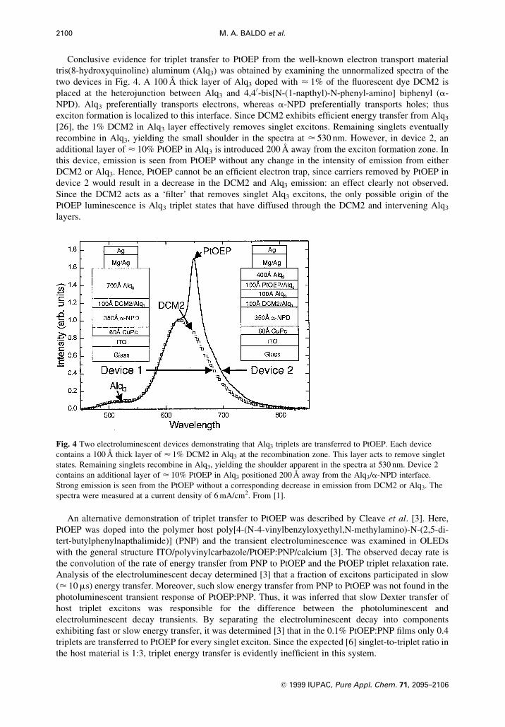
Conclusive evidence for triplet transfer to PtOEP from the well-known electron transport material
tris(8-hydroxyquinoline) aluminum (Alq3) was obtained by examining the unnormalized spectra of the
two devices in Fig. 4. A 100 ÊA thick layer of Alq3 doped with < 1% of the ¯uorescent dye DCM2 is
placed at the heterojunction between Alq3 and 4,40-bis[N-(1-napthyl)-N-phenyl-amino] biphenyl (a-
NPD). Alq3 preferentially transports electrons, whereas a-NPD preferentially transports holes; thus
exciton formation is localized to this interface. Since DCM2 exhibits ef®cient energy transfer from Alq3
[26], the 1% DCM2 in Alq3 layer effectively removes singlet excitons. Remaining singlets eventually
recombine in Alq3, yielding the small shoulder in the spectra at < 530 nm. However, in device 2, an
additional layer of < 10% PtOEP in Alq3 is introduced 200 ÊA away from the exciton formation zone. In
this device, emission is seen from PtOEP without any change in the intensity of emission from either
DCM2 or Alq3. Hence, PtOEP cannot be an ef®cient electron trap, since carriers removed by PtOEP in
device 2 would result in a decrease in the DCM2 and Alq3 emission: an effect clearly not observed.
Since the DCM2 acts as a `®lter' that removes singlet Alq3 excitons, the only possible origin of the
PtOEP luminescence is Alq3 triplet states that have diffused through the DCM2 and intervening Alq3
layers.
An alternative demonstration of triplet transfer to PtOEP was described by Cleave et al. [3]. Here,
PtOEP was doped into the polymer host poly[4-(N-4-vinylbenzyloxyethyl,N-methylamino)-N-(2,5-di-
tert-butylphenylnapthalimide)] (PNP) and the transient electroluminescence was examined in OLEDs
with the general structure ITO/polyvinylcarbazole/PtOEP:PNP/calcium [3]. The observed decay rate is
the convolution of the rate of energy transfer from PNP to PtOEP and the PtOEP triplet relaxation rate.
Analysis of the electroluminescent decay determined [3] that a fraction of excitons participated in slow
(< 10 ms) energy transfer. Moreover, such slow energy transfer from PNP to PtOEP was not found in the
photoluminescent transient response of PtOEP:PNP. Thus, it was inferred that slow Dexter transfer of
host triplet excitons was responsible for the difference between the photoluminescent and
electroluminescent decay transients. By separating the electroluminescent decay into components
exhibiting fast or slow energy transfer, it was determined [3] that in the 0.1% PtOEP:PNP ®lms only 0.4
triplets are transferred to PtOEP for every singlet exciton. Since the expected [6] singlet-to-triplet ratio in
the host material is 1:3, triplet energy transfer is evidently inef®cient in this system.
2100 M. A. BALDO et al.
q 1999 IUPAC, Pure Appl. Chem. 71, 2095±2106
Fig. 4 Two electroluminescent devices demonstrating that Alq3 triplets are transferred to PtOEP. Each device
contains a 100 ÊA thick layer of < 1% DCM2 in Alq3 at the recombination zone. This layer acts to remove singlet
states. Remaining singlets recombine in Alq3, yielding the shoulder apparent in the spectra at 530 nm. Device 2
contains an additional layer of < 10% PtOEP in Alq3 positioned 200 ÊA away from the Alq3/a-NPD interface.
Strong emission is seen from the PtOEP without a corresponding decrease in emission from DCM2 or Alq3. The
spectra were measured at a current density of 6 mA/cm2. From [1].

Owing to long lifetimes, triplet diffusion lengths in organic materials may also be substantially longer
than for singlets. Indeed, it has been found [6] that in Alq3, the triplet diffusion length is > 1400 ÊA, as
compared to singlet diffusion lengths of < 100 ÊA. To optimize ef®ciency, phosphorescent OLEDs can be
modi®ed to trap triplets within the luminescent layer, thereby increasing the probability for energy
transfer from the host to the phorphor. A material suitable for this purpose is 2,9-dimethyl-4,7 diphenyl-
1,10-phenanthroline (bathocuproine, or BCP), which has previously been used as a hole blocking layer in
OLEDs [27]. When placed between a doped HTL and an Alq3 ETL, it was found that light emission
originated from the HTL. As con®rmed by the proposed energy level diagram [28] of Fig. 5, BCP has a
large ionization potential and blocks the passage of holes out of the HTL. These results also suggest that
the lowest unoccupied molecular orbital (LUMO) level of BCP freely allows the transport of electrons
resulting in exciton formation in the HTL. Furthermore, since the energy gap in BCP is < 3.5 eV, it
should act as a barrier to exciton diffusion.
The electroluminescent ef®ciency of PtOEP can also be optimized by the selection of the host
material. For example, the photoluminescent ef®ciency of PtOEP in a 4,40-N,N0-dicarbazole-biphenyl
(CBP) host is approximately twice that of PtOEP in an Alq3 host [29]. The external quantum
ef®ciencies of several OLEDs employing these hosts and a BCP barrier layer are shown in Fig. 6. As
expected, the combination of a CBP host and a BCP barrier layer maximizes PtOEP emission. The
bene®ts of the BCP barrier are most noticeable for the thinner (250 ÊA) luminescent layers, where
energy collection by PtOEP is particularly inef®cient. Here, the quantum ef®ciency in CBP doped
devices is h� (2.2 6 0.1)% at 100 cd/m2, which is nearly twice the reported best result of 1.3% in
PtOEP:Alq3 devices [1]. The peak ef®ciency of h� (5.6 6 0.1)% for the PtOEP:CBP device is
equivalent to an internal quantum ef®ciency of < 32% [30], higher than is expected if only singlet
excitons are transferred to PtOEP molecules [6]. BCP is less useful for devices employing PtOEP in
Organic light emitting devices 2101
q 1999 IUPAC, Pure Appl. Chem. 71, 2095±2106
Fig. 5 Proposed energy level diagram of the electroluminescent devices containing PtOEP. The luminescent
region is sandwiched between electron blocking a-NPD and hole blocking BCP. Also shown are the chemical
structures of (a) Alq3, (b) CBP, (c) PtOEP and (d) BCP.
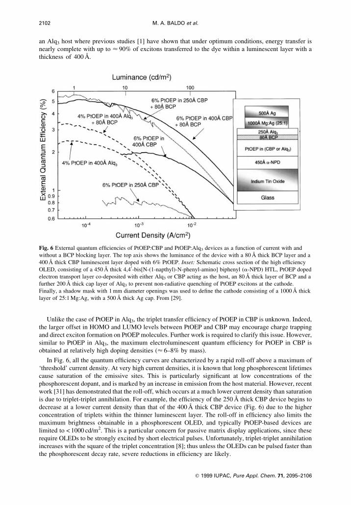
an Alq3 host where previous studies [1] have shown that under optimum conditions, energy transfer is
nearly complete with up to < 90% of excitons transferred to the dye within a luminescent layer with a
thickness of 400 ÊA.
Unlike the case of PtOEP in Alq3, the triplet transfer ef®ciency of PtOEP in CBP is unknown. Indeed,
the larger offset in HOMO and LUMO levels between PtOEP and CBP may encourage charge trapping
and direct exciton formation on PtOEP molecules. Further work is required to clarify this issue. However,
similar to PtOEP in Alq3, the maximum electroluminescent quantum ef®ciency for PtOEP in CBP is
obtained at relatively high doping densities (< 6±8% by mass).
In Fig. 6, all the quantum ef®ciency curves are characterized by a rapid roll-off above a maximum of
`threshold' current density. At very high current densities, it is known that long phosphorescent lifetimes
cause saturation of the emissive sites. This is particularly signi®cant at low concentrations of the
phosphorescent dopant, and is marked by an increase in emission from the host material. However, recent
work [31] has demonstrated that the roll-off, which occurs at a much lower current density than saturation
is due to triplet-triplet annihilation. For example, the ef®ciency of the 250 ÊA thick CBP device begins to
decrease at a lower current density than that of the 400 ÊA thick CBP device (Fig. 6) due to the higher
concentration of triplets within the thinner luminescent layer. The roll-off in ef®ciency also limits the
maximum brightness obtainable in a phosphorescent OLED, and typically PtOEP-based devices are
limited to < 1000 cd/m2. This is a particular concern for passive matrix display applications, since these
require OLEDs to be strongly excited by short electrical pulses. Unfortunately, triplet-triplet annihilation
increases with the square of the triplet concentration [8]; thus unless the OLEDs can be pulsed faster than
the phosphorescent decay rate, severe reductions in ef®ciency are likely.
2102 M. A. BALDO et al.
q 1999 IUPAC, Pure Appl. Chem. 71, 2095±2106
Fig. 6 External quantum ef®ciencies of PtOEP:CBP and PtOEP:Alq3 devices as a function of current with and
without a BCP blocking layer. The top axis shows the luminance of the device with a 80 ÊA thick BCP layer and a
400 ÊA thick CBP luminescent layer doped with 6% PtOEP. Inset: Schematic cross section of the high ef®ciency
OLED, consisting of a 450 ÊA thick 4,40-bis[N-(1-napthyl)-N-phenyl-amino] biphenyl (a-NPD) HTL, PtOEP doped
electron transport layer co-deposited with either Alq3 or CBP acting as the host, an 80 ÊA thick layer of BCP and a
further 200 ÊA thick cap layer of Alq3 to prevent non-radiative quenching of PtOEP excitons at the cathode.
Finally, a shadow mask with 1 mm diameter openings was used to de®ne the cathode consisting of a 1000 ÊA thick
layer of 25:1 Mg:Ag, with a 500 ÊA thick Ag cap. From [29].

Triplet-triplet annihilation and saturation are minimized if the phosphorescent lifetime is short. This
was demonstrated [32] using the green phosphorescent material fac tris(2-phenylpyridine) iridium
(Ir(ppy)3) [22,33±35]. As in the case of PtOEP, Ir(ppy)3 was doped into a CBP host. The device structure
and the proposed energy levels [28] of the charge transport materials are identical for Ir(ppy)3:CBP and
PtOEP:CBP devices (see Fig. 5), although the ionization potentials of PtOEP and Ir(ppy)3 relative to their
hosts are unknown. Once again, it was found that a thin (60 ÊA) BCP barrier layer was necessary to con®ne
excitons within the luminescent zone and achieve high ef®ciencies.
Figure 7 shows the external quantum ef®ciencies of several Ir(ppy)3-based OLEDs. In contrast to
PtOEP-based devices, the Ir(ppy)3 doped devices exhibit a slow decrease in quantum ef®ciency with
increasing current. In addition to the doped device, a heterostructure was fabricated where the
luminescent region was a homogeneous ®lm of Ir(ppy)3. The reduction in ef®ciency to (< 0.8%) of neat
Ir(ppy)3 is re¯ected in the transient decay, which has a lifetime of only < 100 ns as compared with
< 500 ns in the 6% Ir(ppy)3 in CBP devices.
In Fig. 8, the luminance and power ef®ciencies are plotted as functions of voltage. The peak power
ef®ciency is 31 lm/W with a quantum ef®ciency of 8%, (28 cd/A). At 100 cd/m2, a power ef®ciency of
19 lm/W with a quantum ef®ciency of 7.5% (26 cd/A) is obtained at a voltage of 4.3 V. The transient
response of Ir(ppy)3 in CBP is an approximately mono-exponential phosphorescent decay of < 500 ns,
compared with a measured lifetime [22,33,34] of 2 ms in degassed toluene at room temperature. Slow
triplet relaxation can form a bottleneck in electrophosphorescence, thereby encouraging triplet-triplet
annihilation [31] and saturation. But these lifetimes are short and result in only a gradual decrease in
ef®ciency with increasing current, leading to a maximum luminance of < 100 000 cd/m2.
Organic light emitting devices 2103
q 1999 IUPAC, Pure Appl. Chem. 71, 2095±2106
Fig. 7 The external quantum ef®ciency of OLEDs using Ir(ppy)3:CBP luminescent layers. Peak ef®ciencies are
observed for mass ratio of 6% Ir(ppy)3:CBP. The 100% Ir(ppy)3 device has a slightly different structure than
shown in Fig. 1: the Ir(ppy)3 layer is 300 ÊA thick and there is no BCP blocking layer. The ef®ciency of a 6%
Ir(ppy)3:CBP device grown without a BCP layer is also shown. From [32].
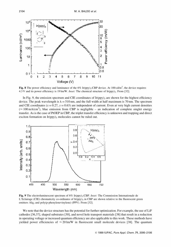
In Fig. 9, the emission spectrum and CIE coordinates of Ir(ppy)3 are shown for the highest ef®ciency
device. The peak wavelength is l� 510 nm, and the full width at half maximum is 70 nm. The spectrum
and CIE coordinates (x� 0.27, y� 0.63) are independent of current. Even at very high current densities
(< 100 mA/cm2), blue emission from CBP is negligible ± an indication of complete singlet energy
transfer. As is the case of PtOEP in CBP, the triplet transfer ef®ciency is unknown and trapping and direct
exciton formation on Ir(ppy)3 molecules cannot be ruled out.
We note that the device structure has the potential for further optimization. For example, the use of LiF
cathodes [36,37], shaped substrates [30], and novel hole transport materials [38] that result in a reduction
in operating voltage or increased quantum ef®ciency are also applicable to this work. These methods have
yielded power ef®ciencies of < 20 lm/W in ¯uorescent small molecule devices [38]. The quantum
2104 M. A. BALDO et al.
q 1999 IUPAC, Pure Appl. Chem. 71, 2095±2106
Fig. 8 The power ef®ciency and luminance of the 6% Ir(ppy)3:CBP device. At 100 cd/m2, the device requires
4.3 V and its power ef®ciency is 19 lm/W. Inset: The chemical structure of Ir(ppy)3. From [32].
Fig. 9 The electroluminescent spectrum of 6% Ir(ppy)3:CBP. Inset: The Commission Internationale de
L'Eclairage (CIE) chromaticity co-ordinates of Ir(ppy)3 in CBP are shown relative to the ¯uorescent green
emitters Alq3 and poly(p-phenylenevinylene) (PPV). From [32].
ef®ciencies in these devices [39] at 100 cd/m2 are typically > 5%, and hence green-emitting
electrophosphorescent devices with power ef®ciencies of > 40 lm/W are anticipated.
RELIABILITY OF PHOSPHORESCENT OLEDs
The suitability of semiconducting organic thin ®lms for practical use is ultimately determined by device
reliability. Unless OLEDs can demonstrate thousands of hours of high performance then applications will
be scarce. But ¯uorescent OLEDs have already achieved such standards [40] and there is no reason to
believe that phosphorescent materials should be any less stable; they may in fact improve reliability. For
example, there has been speculation that molecules in the triplet state may be particularly susceptible to
degradation because of the long lifetime of the excitation [41]. Although the triplet lifetime of phosphors
possessing signi®cant ISC may approach < 100 ms, these lifetimes are still much shorter than those in
¯uorescent materials, where the triplet decay is strongly forbidden. Thus, it is possible that by acting as
sinks for triplet excitations, phosphorescent materials may in fact ultimately improve device reliability.
Owing to the novelty of phosphorescent dyes, there is little data to test such a contention. But
preliminary reliability data is available for PtOEP-based OLEDs, and a lifetime of > 105 h at a luminance
of 35 cd/m2 is observed for OLEDs incorporating PtOEP. This is at least as reliable as the longest lived
¯uorescent devices employing all the same materials except PtOEP. Another study [42] has identi®ed a
derivative of PtOEP for oxygen sensing applications, where long operational lifetimes are required in
relatively uncontrolled environments.
CONCLUSION
Although this work has highlighted the performance advantages inherent to phosphorescence, these
advantages are eliminated if the phosphor cannot ef®ciently gather triplet and singlet excitons within the
device. For example, the lanthanide complexes exhibit losses in energy transfer within the complex, and
also between the host and the complex; and unless these de®ciencies can be overcome it is unlikely that
lanthanide complexes will ®nd application in OLEDs. In contrast, ef®cient triplet energy transfer and
possibly direct charge trapping and exciton formation is partly responsible for the success of
organometallic compounds such as PtOEP and Ir(ppy)3. Since organometallic complexes featuring L-S
coupling are the most successful phosphors to date, similar complexes that phosphoresce at different
wavelengths deserve investigation. In particular, blue phosphorescent OLEDs present a challenge since
wide-gap (< 3.5 eV) host materials and luminescent complexes will be required to overcome exchange
energy losses. It is clear, however, that the ef®ciency improvements offered by phosphorescence
outweigh the slight increase in voltage that results from the use of large-energy-gap materials.
Furthermore, triplet energy transfer remains poorly characterized, and if these mechanisms can be better
understood improvements in device structure and host material combinations may yet result in further
enhancements in phosphorescent device performance.
ACKNOWLEDGEMENT
We thank Dr C. Adachi for many useful discussions. This work was funded by Universal Display
Corporation, DARPA, AFOSR and NSF.
REFERENCES
1 M. A. Baldo, D. F. O'Brien, Y. You, A. Shoustikov, S. Sibley, M. E. Thompson, S. R. Forrest. Nature 395, 151
(1998).
2 Y. Ma, H. Zhang, J. Shen, C. Che. Synth. Met. 94, 245 (1998).
3 V. Cleave, G. Yahioglu, P. Le Barny, R. Friend, N. Tessler. Adv. Mat. 11, 285 (1999).
4 S. Hoshino, H. Suzuki. Appl. Phys. Lett. 69, 224 (1996).
5 J. Kido, K. Nagai, Y. Ohashi. Chem. Lett. 657 (1990).
6 M. A. Baldo, D. F. O'Brien, M. E. Thompson, S. R. Forrest. Phys. Rev. B 60, 14422 (1999).
7 C. W. Tang, S. A. VanSlyke, C. H. Chen. J. Appl. Phys. 65, 3610 (1989).
Organic light emitting devices 2105
q 1999 IUPAC, Pure Appl. Chem. 71, 2095±2106

8 M. Klessinger, J. Michl. Excited States and Photochemistry of Organic Molecules. VCH Publishers, New York
(1995).
9 T. Forster. Disc. Faraday Soc. 27, 7 (1959).
10 V. L. Ermolaev, E. B. Sveshnikova. Doklady Akademii Nauk SSSR 148, 1295 (1963).
11 M. A. Baldo, M. E. Thompson, S. R. Forrest. Nature 403, 750 (2000).
12 D. L. Dexter. J. Chem. Phys. 21, 836 (1953).
13 S. P. Sinha. Complexes of the Rare Earths. Pergamon, Oxford (1966).
14 J. Kido, K. Nagai, Y. Okamoto, T. Skotheim. Chem. Lett. 1267 (1991).
15 J. Kido, H. Hayese, K. Hongawa, K. Nagai, K. Okuyama. Appl. Phys. Lett. 65, 2124 (1994).
16 R. J. Curry, W. P. Gillin. Appl. Phys. Lett. 75, 1380 (1999).
17 C. Adachi, T. Tsutsui, S. Saito. Appl. Phys. Lett. 55, 1489 (1989).
18 M. L. Bhaumik, M. A. El-Sayed. J. Chem. Phys. 42, 787 (1965).
19 F. J. Steemers, W. Verboom, D. N. Reinhoudt, E. B. van der Tol, W. Verhoeven. J. Am. Chem. Soc. 117, 9408
(1995).
20 P. W. Atkins, R. S. Friedman. Molecular Quantum Mechanics. Oxford University Press, New York (1997).
21 D. B. Papkovski. Sens. and Actuators B 29, 213 (1995).
22 E. Vander Donckt, B. Camerman, F. Hendrick, R. Herne, R. Vandeloise. Bull. Soc. Chim. Belg. 103, 207 (1994).
23 Y. Ma, C.-M. Che, H.-Y. Chao, X. Zhou, W.-H. Chan, J. Shen. Adv. Mat. 11, 852 (1999).
24 A. Mills, A. Lepre. Anal. Chem. 69, 4653 (1997).
25 G. Ponterini, N. Serpone, M. A. Bergkamp, T. L. Netzel. J. Am. Chem. Soc. 105, 4639 (1983).
26 V. Bulovic, A. Shoustikov, M. A. Baldo, E. Bose, V. G. Kozlov, M. E. Thompson, S. R. Forrest. Chem. Phys.
Lett. 287, 455 (1998).
27 Y. Kijima. In Mat. Res. Soc., San Francisco, California (1998).
28 I. G. Hill, A. Kahn. J. Appl. Phys. 86, 4515 (1999).
29 D. F. O'Brien, M. A. Baldo, M. E. Thompson, S. R. Forrest. Appl. Phys. Lett. 74, 442 (1999).
30 G. Gu, D. Z. Garbuzov, P. E. Burrows, S. Venkatesh, S. R. Forrest, M. E. Thompson. Op. Lett. 22, 396 (1997).
31 M. A. Baldo, C. Adachi, S. R. Forrest. (1999). Unpublished.
32 M. A. Baldo, S. Lamansky, P. E. Burrows, M. E. Thompson, S. R. Forrest. Appl. Phys. Lett. 75, 4 (1999).
33 K. A. King, P. J. Spellane, R. J. Watts. J. Am. Chem. Soc. 107, 1431 (1985).
34 K. Dedeian, P. I. Djurovich, F. O. Garces, G. Carlson, R. J. Watts. Inorg. Chem. 30, 1685 (1991).
35 M. G. Colombo, T. C. Brunold, T. Riedener, H. U. Gudel, M. Fortsch, H.-B. Burgi. Inorg. Chem. 33, 545 (1994).
36 L. S. Hung, C. W. Tang, M. G. Mason. Appl. Phys. Lett. 70, 152 (1997).
37 G. E. Jabbour, Y. Kawabe, S. E. Shaheen, J. F. Wang, M. M. Morrell, B. Kippelen, N. Peyghambarian. Appl.
Phys. Lett. 71, 1762 (1997).
38 B. Kippelen, G. E. Jabbour, S. E. Shaheen, et al. In Mat. Res. Soc., San Francisco, California (1999).
39 J. Kido, Y. Iizumi. Appl. Phys. Lett. 73, 2721 (1998).
40 J. Shi, C. W. Tang. Appl. Phys. Lett. 70, 1665 (1997).
41 G. Sakamoto, C. Adachi, T. Koyama, Y. Taniguchi, C. D. Merrit, H. Murata, Z. H. Kafa®. Appl. Phys. Lett. 75,
766 (1999).
42 S.-K. Lee, I. Okura. Anal. Comm. 34, 185 (1997).
2106 M. A. BALDO et al.
q 1999 IUPAC, Pure Appl. Chem. 71, 2095±2106