phonon transport at interfaces: determining the correct ... transport at interfaces: determining the...
TRANSCRIPT

Phonon transport at interfaces: Determining the correct modes of vibrationKiarash Gordiz and Asegun Henry Citation: Journal of Applied Physics 119, 015101 (2016); doi: 10.1063/1.4939207 View online: http://dx.doi.org/10.1063/1.4939207 View Table of Contents: http://scitation.aip.org/content/aip/journal/jap/119/1?ver=pdfcov Published by the AIP Publishing Articles you may be interested in Thermoelectric transport coefficients in mono-layer MoS2 and WSe2: Role of substrate, interface phonons,plasmon, and dynamic screening J. Appl. Phys. 118, 135711 (2015); 10.1063/1.4932140 Anharmonicity and necessity of phonon eigenvectors in the phonon normal mode analysis J. Appl. Phys. 117, 195102 (2015); 10.1063/1.4921108 Kapitza resistance of Si/SiO2 interface J. Appl. Phys. 115, 084910 (2014); 10.1063/1.4867047 Large effects of pressure induced inelastic channels on interface thermal conductance Appl. Phys. Lett. 101, 221903 (2012); 10.1063/1.4766266 In-plane phonon transport in thin films J. Appl. Phys. 107, 024317 (2010); 10.1063/1.3296394
[This article is copyrighted as indicated in the article. Reuse of AIP content is subject to the terms at: http://scitation.aip.org/termsconditions. Downloaded to ] IP:
128.61.141.183 On: Mon, 04 Jan 2016 22:03:50

Phonon transport at interfaces: Determining the correct modes of vibration
Kiarash Gordiz1 and Asegun Henry1,2,a)
1George W. Woodruff School of Mechanical Engineering, Georgia Institute of Technology, Atlanta,Georgia 30332, USA2School of Materials Science and Engineering, Georgia Institute of Technology, Atlanta, Georgia 30332, USA
(Received 1 October 2015; accepted 17 December 2015; published online 4 January 2016)
For many decades, phonon transport at interfaces has been interpreted in terms of phonons
impinging on an interface and subsequently transmitting a certain fraction of their energy into the
other material. It has also been largely assumed that when one joins two bulk materials, interfacial
phonon transport can be described in terms of the modes that exist in each material separately.
However, a new formalism for calculating the modal contributions to thermal interface conductance
with full inclusion of anharmonicity has been recently developed, which now offers a means for
checking the validity of this assumption. Here, we examine the assumption of using the bulk
materials’ modes to describe the interfacial transport. The results indicate that when two materials
are joined, a new set of vibrational modes are required to correctly describe the transport. As the
modes are analyzed, certain classifications emerge and some of the most important modes are
localized at the interface and can exhibit large conductance contributions that cannot be explained by
the current physical picture based on transmission probability. VC 2016 AIP Publishing LLC.
[http://dx.doi.org/10.1063/1.4939207]
I. INTRODUCTION
The current and prevailing view point for describing
phonon transport at interfaces is based on the phonon gas
model (PGM), which treats phonons as gas particles that
impinge on an interface. It is then believed that when a pho-
non reaches the interface, there is a certain probability that
its energy will be transmitted, which is referred to as its
transmission probability. It is also almost ubiquitously
assumed that when two bulk materials are joined, the modes
of each material are largely unchanged, and the transport at
the interface can be described in terms of the modes that
would exist in each bulk material separately. A study by
Landry and McGaughey1 suggested that such an approach
exhibits agreement with the interface conductance calcu-
lated from non-equilibrium molecular dynamics (NEMD)
simulations and independent lattice dynamics based
approaches. However, although widely used,2–7 these ideas
have never actually been proven, i.e., by demonstrating
excellent agreement with experiments, as has been done
with first principles approaches to thermal conductivity.8,9
Thus, it is important to consider alternative perspectives
that might provide more accurate and complete descriptions
of the physics.
Intuitively, based on the abrupt change in vibrational
character, one might expect that non-propagating and possi-
bly localized modes might exist at an interface. However,
what has been lacking is an approach for identifying or
studying such modes, and the ultimate goal would be to
assess whether their role in interfacial transport is even im-
portant. Here, we discuss the recently developed interface
conductance modal analysis (ICMA) method developed by
Gordiz and Henry,10 which naturally not only includes the
crucial effect of anharmonicity but also allows one to exam-
ine the validity of the assumption that one can describe inter-
facial transport in terms of the bulk material’s modes.
In essence, the ICMA formalism is based on performing
a modal decomposition of the heat flow at an interface and
then substituting the modal contributions into either an equi-
librium molecular dynamics (EMD) or NEMD expression
for thermal interface conductance (TIC). The key question
then becomes: Which set of modes should one use in the
heat flow decomposition to calculate physically meaningful
contributions? This is important, because any mathemati-
cally complete set is guaranteed to return the same total heat
flow. However, different choices might ascribe different
amounts of the heat flow and contributions to TIC to differ-
ent frequencies. This is critical because different spectral
contributions might then lead to different temperature de-
pendent TIC predictions when quantum effects on the heat
capacity are accounted for (i.e., by applying approximate
quantum corrections).11,12 For example, if the TIC is domi-
nated by low frequency modes, the temperature regime
where it will decrease towards zero at low temperatures may
be quite low, versus if it is dominated by higher frequency
modes, the temperature regime where TIC will decrease
towards zero at low temperatures may occur at somewhat
higher temperatures.
Before addressing this question, we first review the
ICMA formalism in Section II. (More details can be found in
Ref. 10.) Then, in Section III, different modal basis sets will
be investigated for two different interfaces by both EMD and
wave-packet (WP) simulations to determine the correct basis
set. The two structures examined are the interface of two
lattice-matched mass-mismatched Lennard-Jones (LJ) solids
a)Author to whom correspondence should be addressed. Electronic mail:
0021-8979/2016/119(1)/015101/12/$30.00 VC 2016 AIP Publishing LLC119, 015101-1
JOURNAL OF APPLIED PHYSICS 119, 015101 (2016)
[This article is copyrighted as indicated in the article. Reuse of AIP content is subject to the terms at: http://scitation.aip.org/termsconditions. Downloaded to ] IP:
128.61.141.183 On: Mon, 04 Jan 2016 22:03:50

and the interface of two lattice-matched mass-mismatched
solids described by Tersoff interatomic potential. Having
defined the correct modal basis set, deeper understanding of
the physics can be obtained by classifying the modes of
vibration (Section IV) and analyzing the map of correlations
(Section V). Finally, our conclusions are presented in
Section VI.
II. ICMA FORMALISM
Consider forming an interface by bringing two systems
A and B into contact, each having NA and NB atoms. We can
use the lattice-dynamics (LD) formalism13 to obtain the
complete 3N¼ 3(NAþNB) eigen solutions to the equations
of motion describing the vibrations of the system when all
the interactions are considered to be harmonic. These eigen
solutions allow us to write the atomic displacements and
velocities as
xi ¼X
n
1
Nmið Þ1=2en;iXn; (1)
_xi ¼X
n
1
Nmið Þ1=2en;i
_Xn; (2)
where n is the index for the eigen mode; xi, _xi, and mi are the
displacement from equilibrium, velocity, and mass of atom irespectively; and en;i is the eigen vector for mode n assigning
the direction and displacement magnitude of atom i. From
the inverse of the operations in Eqs. (1) and (2), we can
define the normal mode coordinates of position and velocity
for mode n (Xn and _Xn) as
Xn ¼X
i
m1=2i
N1=2xi � e�n;i; (3)
_Xn ¼X
i
m1=2i
N1=2_xi � e�n;i; (4)
where i is the index for the atom in the system, and � repre-
sents complex conjugate. A system of N atoms has a
Hamiltonian given by
H ¼XN
i
pi2
2miþ U r1; r2;…; rnð Þ; (5)
where U is the total potential energy of the system, and the
position and momentum of atom i are denoted by ri and pi,
respectively. From Eq. (5), the individual Hamiltonian for
atom i can be written as
Hi ¼pi
2
2miþ Ui r1; r2;…; rnð Þ; (6)
where Ui is the potential energy assigned to a single
atom.14,15 Using the above definition of the Hamiltonian for
an individual atom, the energy exchanged between materials
A and B at each instant of time can be written as
QA!B ¼ �Xi2A
Xj2B
pi
mi� �@Hj
@ri
� �þ
pj
mj� @Hi
@rj
� �( ); (7)
which is a general equation that is valid for any interatomic
potential, as long as it can be written as a sum of individual
atom energies. For the case of having pairwise interactions
between materials A and B, Eq. (7) is reduced to
QA!B ¼ �1
2
Xi2A
Xj2B
f ij � _xi þ _xjð Þ; (8)
where f ij is the pairwise exchanged force between atoms iand j in the two materials.16–18 Having pairwise interactions,
half of the interaction energy is naturally partitioned with
atom i and the other half with atom j. Using Eq. (8) and
fluctuation-dissipation theorem,19 Domingues et al.17
showed that the TIC is proportional to the correlation
between the equilibrium heat flow fluctuations via
G ¼ 1
AkBT2
ð10
hQA!B tð Þ � QA!B 0ð Þidt; (9)
where G is the TIC between materials A and B, A is the
cross-sectional contact area, kB is the Boltzmann constant, Tis the equilibrium system temperature, and h� � �i indicates
the calculation of the autocorrelation function. For simplic-
ity, we will use Q instead of QA!B for interfacial heat flow in
the ensuing discussion.
It can be seen from Eq. (9) that if one can obtain the modal
contributions to the interfacial heat flow such that at each
instant the obtained modal contributions sum to the total Q
Q ¼X
n
Qn; (10)
then G can be rewritten as
G ¼ 1
AkBT2
ð Xn
Qn tð Þ � Q 0ð Þ* +
dt
¼X
n
1
AkBT2
ðhQn tð Þ � Q 0ð Þidt: (11)
This then yields the individual modal contributions to G as
Gn ¼1
AkBT2
ðhQn tð Þ � Q 0ð Þidt; (12)
where
G ¼X
n
Gn: (13)
Furthermore, the modal heat flux definition in Eq. (10)
allows us to substitute for both of the total heat fluxes in Eq.
(9) leading to another definition for G as
G ¼ 1
AkBT2
ð Xn
Qn tð Þ �X
n0Qn0 tð Þ
* +dt
¼X
n
Xn0
1
AkBT2
ðhQn tð Þ � Qn0 0ð Þidt; (14)
015101-2 K. Gordiz and A. Henry J. Appl. Phys. 119, 015101 (2016)
[This article is copyrighted as indicated in the article. Reuse of AIP content is subject to the terms at: http://scitation.aip.org/termsconditions. Downloaded to ] IP:
128.61.141.183 On: Mon, 04 Jan 2016 22:03:50

where individual contributions from pairs of modes equal to
Gn;n0 ¼1
AkBT2
ðhQn tð Þ � Qn0 0ð Þidt: (15)
This definition represents the TIC as the summation of
all the auto-correlations and cross-correlations between eigen
mode pairs n and n0 in the system (G ¼P
n;n0 Gn;n0) and pro-
vides new insight into the degree to which each pair of
modes interact and contribute to interface conductance. As a
result, the ICMA method presented above contains more
detail and can potentially lead to deeper insights into the
physics of TIC.
The important step is then to determine Qn, with the
requirement of Eq. (10) (i.e., Q ¼P
n Qn), which can be
accomplished by replacing the atomic velocities in Eq. (7)
with their modal definition in Eq. (2)
Q ¼Xi2A
Xj2B
Xn
1
Nmið Þ1=2en;i
_Xn
!� @Hj
@ri
� ��
Xn
1
Nmjð Þ1=2en;j
_Xn
!� @Hi
@rj
� �( );
Qn ¼1
N1=2
Xi2A
Xj2B
1
mið Þ1=2en;i
_Xn
!� @Hj
@ri
� �þ 1
mjð Þ1=2en;j
_Xn
!� �@Hi
@rj
� �( ): (16)
Equation (16) is general and it can be simplified for pairwise
interactions to
Qn¼Xi2A
Xj2B
�f ij
2� 1
Nmið Þ1=2en;i
_Xnþ1
Nmjð Þ1=2en;j
_Xn
!: (17)
Equations (16) and (17) are the definitions of modal contri-
butions to interfacial heat flow.
III. MODAL BASIS SETS
Towards finding the correct set of modes to be used in
the heat flow decomposition, we have identified three poten-
tial options for the modal decomposition of the interfacial
heat flow (Eqs. (16) and (17)). If we consider two bulk mate-
rials labeled A and B, respectively, when they are joined and
form an interface, the three choices for describing the modes
that contribute to heat flow through their interface are
denoted by {A/B}, {AþB}, and {AB}. The basis set {A/B}
corresponds to the modes associated with the bulk of either
material A or B, where one performs a LD calculation for
each individual bulk material. The modal basis set {AþB}
corresponds to the addition of the eigen solutions for each
separate bulk material, whereby one simply assigns polariza-
tion vectors equal to zero for the atoms on side B, for modes
on side A, and vice versa. The third choice is then basis set
{AB}, which corresponds to the modes obtained from a LD
calculation for the entire structure, containing both materials
A and B along with their interface. The basis set choices {A/
B} and {AþB} are conceptually consistent with the current
view of interface transport, since they correspond to the
modes of the bulk material and for crystals are guaranteed to
yield all propagating modes that have well-defined veloc-
ities. Using the bulk modes, which have well-defined veloc-
ities, is critical to the current paradigm, because the PGM
description of TIC casts each mode’s contribution as propor-
tional to its velocity.5,20 Thus, a non-propagating or localized
mode’s contribution is ill-defined in the current paradigm,
and it is therefore of critical importance to determine if
{A/B} and/or {AþB} can still be used to describe interfa-
cial transport.
The correct basis set can be determined based on purely
theoretical considerations, because it must reproduce the
expected behavior in the harmonic limit (e.g., as T! 0K).
As T! 0K, the atomic interactions approach that of a per-
fectly harmonic potential, which then leads to purely elastic
interactions, whereby modes can only transfer their energy
to other modes with the same frequency. In general, there
could be modes on one side of the interface (denoted side A)
that are above the maximum frequency that can be supported
on side B, which we label as the heavier or weaker material
with a lower maximum vibration frequency denoted by
xmax;B. Modes with frequencies above xmax;B on side A have
no corresponding mode with the same frequency on side B
to exchange energy through elastic interactions. Therefore,
in the T! 0K limit, these modes cannot contribute to the
TIC when anharmonic coupling is disabled. It is important to
note that this effect is correctly reproduced by MD simula-
tions, as the WP method shows that modes above xmax;B
have 0% transmission.4,21–23 This behavior is also well
understood and reproduced by other established methods,
such as the AGF method, since the majority of
implementations of the AGF method are based on an elastic
scattering assumption.3,6,7,24,25 Thus, by simply testing
which basis sets show zero contributions to the TIC from
modes above xmax;B as T! 0K, we can determine which
basis is correct.
Here, we studied a simple interface between lattice
matched LJ face-centered cubic (FCC) solids. The LJ poten-
tial is defined based on the following formula:26
U ¼ 4err
� �12
� rr
� �6" #
; (18)
where e and r are the energy and distance parameters and ris the distance between two interacting atoms. We select
equal values of e and r for both materials A and B, which
results in equal lattice constants for the two sides. An
015101-3 K. Gordiz and A. Henry J. Appl. Phys. 119, 015101 (2016)
[This article is copyrighted as indicated in the article. Reuse of AIP content is subject to the terms at: http://scitation.aip.org/termsconditions. Downloaded to ] IP:
128.61.141.183 On: Mon, 04 Jan 2016 22:03:50

acoustic mismatch exists at the interface because the mass of
the atoms on side B are four times the mass of atoms on side
A (mB ¼ 4mA). Both sides have FCC lattice structures. In LJ
systems, the simulations can be performed in LJ dimension-
less units,27 but to have the results correspond to a physically
meaningful system, we chose LJ parameters in our simula-
tions to be equal to that of argon (e ¼ 1:67� 10�21J,
r ¼ 3:405A, and mA ¼ 6:6� 10�26kg (Ref. 28)). Thus, side
A represents solid argon (mass m) and side B represents a
fictitiously heavier solid argon (mass 4m) and by averaging
an isobaric-isothermal simulation at zero pressure and
T¼ 1 K, the lattice constant was calculated as 5:26A.
A. EMD simulations
In our EMD simulations for the interface between LJ
crystals, the system consists of 3 � 3 � 60 FCC unit cells
(each side 30 unit cells long), which includes 2160 atoms
and 6480 eigen modes. We confirmed that increasing the
size of cross section does not change the features observed in
the results, which is in agreement with other reports.16,25
Initially, an equilibration period equal to 2 ns is performed.
Then, modal heat flux contributions (Qn) are recorded for
5 ns in the micro-canonical ensemble. The modal contribu-
tions to the heat flow, Qn, are then used in post processing,
which leads to the calculation of modal thermal conductance
(Gn). A time step of 1 fs was chosen for the simulations, and
ten independent ensembles were simulated to reduce the
standard deviation in TIC below 5%.29 The TIC accumula-
tion function was then computed for all three basis sets
according to the ICMA formalism10 and is shown in Fig. 1.
At a temperature of 1 K, only the {AB} basis set shows the
qualitatively correct behavior as all of the contributions
above xmax;B decay to zero. Both the {A/B} and {AþB} ba-
sis sets, however, still attribute large portions of the TIC to
frequencies that only exist in the bulk of side A and cannot
transmit any energy to side B.
It should be noted that 0% transmission above xmax;B
was also observed for a perfectly smooth interface between
two lattice matched diamond structured materials, modeled
with the Tersoff potential,30 using parameters for Si on both
sides of the interface and Si with a 4� larger mass on the
other. For this structure, we used EMD simulations to calcu-
late the modal contributions to TIC. The system consists of 3
� 3 � 36 diamond unit cells (each side 18 unit cells long),
which includes 2592 atoms and 7776 eigen modes of vibra-
tion. By averaging in an isobaric-isothermal simulation at
zero pressure and T¼ 1 K, the lattice constant was calculated
as 5:43A. The temperature of the simulation is set to
T¼ 1 K. Initially, an equilibration period of 5 ns under the
NPT ensemble is performed. Then, modal heat flux contribu-
tions (Qn) were recorded for 10 ns in the micro-canonical en-
semble. The modal contributions to the heat flow, Qn, are
then used in post processing, which leads to the calculation
of modal thermal conductance (Gn). A time step of 0.5 fs
was chosen for the simulations, and ten independent ensem-
bles were simulated to reduce the standard deviation in TIC
below 5%. The accumulations have been calculated for dif-
ferent basis sets and are presented in Fig. 2. Again, by using
the {AB} basis set, no contribution to the TIC from frequen-
cies above xB;max was observed, yet for the {A/B} and
{AþB} bases, the frequency dependence is qualitatively
incorrect. Since only the {AB} basis set yields the qualita-
tively correct behavior in both cases, our conclusion is that
{AB} is the correct choice.
FIG. 1. Modal contributions to interface conductance at T¼ 1 K at the inter-
face of two lattice matched, mass mismatched LJ solids calculated using dif-
ferent basis sets. {A/B} basis set can either express the modes on the bulk of
side A or on the bulk of side B. The modal contributions from these two ba-
sis sets are shown in the figure using {A} and {B}, respectively. Since the
{B} basis set is based on the heavier side of the interface, the maximum
frequency in this basis set is xmax;B; therefore, the contributions by higher
frequencies cannot be calculated using the {B} basis set.
FIG. 2. Thermal interface conductance accumulation for different basis sets
at the interface of a lattice matched, mass-mismatched silicon diamond
structured system. Accumulation is calculated at a temperature of T¼ 1 K.
{A/B} basis set can either express the modes on the bulk of side A or on the
bulk of side B. The modal contributions from these two basis sets are shown
in the figure using {A} and {B}, respectively. Since the {B} basis set is
based on the heavier side of the interface, the maximum frequency in this
basis set is xmax;B; therefore, the contributions by higher frequencies cannot
be calculated using the {B} basis set.
015101-4 K. Gordiz and A. Henry J. Appl. Phys. 119, 015101 (2016)
[This article is copyrighted as indicated in the article. Reuse of AIP content is subject to the terms at: http://scitation.aip.org/termsconditions. Downloaded to ] IP:
128.61.141.183 On: Mon, 04 Jan 2016 22:03:50

B. Wave-packet simulations
To understand why {A/B} and {AþB} yield qualita-
tively incorrect behavior, a test was devised based on the
WP method, whereby only a narrow range of frequencies
with a single polarization is excited, and all other modes
have zero amplitude which approximates T! 0K. The WP
is launched towards the interface22,23 from bulk of side A,
and when it reaches the interface it elastically scatters, and a
fraction of its energy is transmitted into modes with similar
frequency on side B. We form the WP from the longitudinal
polarization by displacing the atoms in the system according
to Ref. 22
ui ¼ A0eiðk0Þ exp ½ik0ðz� z0Þ� exp ½�g2ðz1 � z0Þ2�; (19)
where the plane of the interface is perpendicular to the z-
direction, A0 is the amplitude of the wave packet, k0 is the
central wave vector for the WP, ei (k0) is the polarization
vector for mode k0 attributed to atom i, g is the spatial extent
of the WP, and z0 is the initial central location for the WP.22
For the WP simulations in this study, we set the parameters
to be A ¼ 0:00001a0, k0 ¼ 0:2 2pa0
, g ¼ 50a0, and z0 ¼ 150a0,
where a0 is the lattice constant for solid argon. Initial atomic
velocities are assigned based on the differentiation of Eq.
(19) with respect to time.22 Initially, the WP has a certain
amount of energy (Einit:), and when it reaches the interface,
part of its energy is transmitted (Etrans:) and the remainder is
reflected (Erefl:). The polarization of both the reflected and
transmitted WPs can be different from the incident WP; how-
ever, both should have the same frequencies as the incident
WP.22 In the previous WP studies, the energy of different
modes is studied and the transmission (s) is computed from23
s ¼ Etrans:
Einit:: (20)
Using Eq. (17), the modal contributions to the interfacial
heat flow are tracked in time for all three choices: {A/B},
{AþB}, and {AB}. For a correct basis set, the following
two features should be observed: (1) Since the scattering
event will be purely elastic, as the WP reaches the interface,
FIG. 3. Modal contributions to interfacial heat flow for the WP simulation at the interface of two lattice matched, mass mismatched LJ solids calculated using
different basis sets of (a) {A}, (b) {B}, (c) {AþB}, and (d) {AB}. The data represent three different instants: before the impact (t1), during the impact (t2),
and after the impact (t3). The atomic displacement profiles at these three times are shown as insets in (a). The dashed lines show (Dx) the range of frequencies
in the originally excited WP. Since the {B} basis set is based on the heavier side of the interface, the maximum frequency in this basis set is
xmax;B � 1:03THz; therefore, the contributions by higher frequencies cannot be calculated using the {B} basis set.
015101-5 K. Gordiz and A. Henry J. Appl. Phys. 119, 015101 (2016)
[This article is copyrighted as indicated in the article. Reuse of AIP content is subject to the terms at: http://scitation.aip.org/termsconditions. Downloaded to ] IP:
128.61.141.183 On: Mon, 04 Jan 2016 22:03:50

we should only observe heat flow contributions Qn associ-
ated with the original modes in the WP on side A or the
modes in the transmitted WP on side B and (2) If we inte-
grate Qn in time, we should see that only the modes that par-
ticipate in the incoming or outgoing WPs contribute to the
energy transfer across the interface. Figure 3 shows that {A/
B} and {AþB} do not exhibit these features, as they both
show frequency broadening when the WP reaches the inter-
face. This is unphysical because the frequency content of all
the atomic motions before, during, and after the scattering
event all lie within the same frequency range as the original
WP. Therefore, the broadening exhibited by {A/B} and
{AþB} is not representative of actual excitation of those
frequencies. Instead, this broadening is a type of aliasing,
since the modes in {A/B} and {AþB} do not contain infor-
mation about the interface condition or bonding. Therefore,
{A/B} and {AþB} ascribe contributions to modes that are
not actually excited, which is why they assign large TIC con-
tributions to modes with frequencies>xmax;B as
T! 0 K(45% and 22%, respectively). However, only when
the combined system {AB} is used are all of the theoretical
requirements satisfied.
IV. CLASSIFICATION OF THE MODES OF VIBRATION
With the correct choice of modes now established, we
turn our discussion to a deeper examination of the modes
contained in the {AB} basis set. The interface itself acts as a
compositional discontinuity that breaks the system’s symme-
try and changes the LD dynamical matrix in such a way that
not all solutions can retain sinusoidally modulated eigen vec-
tors for all of the atoms. Therefore, not all of the modes from
the {AB} basis set correspond to propagating modes.
Furthermore, since atoms near the interface have different
dynamical matrix elements than the rest of the system, some
of the eigen solutions become localized to the interfacial
region (i.e., similar to localization of vibrational modes near
defects).31 Given that some degree of localization is to be
expected, new mode classifications can emerge. One can
then envision developing a mode classification scheme based
on the degree to which modes are localized to a given por-
tion of the system. For example, Eqs. (16) and (17) indicate
that a mode can only contribute substantively to the heat
flow, if it includes participation (e.g., significant eigen vec-
tors) from atoms near the interface. Thus, a mode with zero
eigen vectors for the atoms near the interface will by defini-
tion have zero contribution to the heat flow and therefore
zero contribution to the TIC. Also, a mode that can extend
through both sides of the interface and deeply into both
materials has a greater likelihood of exhibiting longer corre-
lation times, resulting in larger contributions to the TIC (see
Eq. (9)). From this perspective, one might obtain new and
interesting insights by classifying the modes in the {AB} ba-
sis set according to (1) the degree of delocalization into both
materials, (2) the degree of localization in one material, (3)
the degree of participation near the interface, or (4) the
degree of localization near the interface.
We have tentatively classified the 3 N solutions in the
{AB} basis set into 4 distinct categories based on the region
where they are most localized: h1i extended modes, h2i partially
extended modes, h3i isolated modes, and h4i interfacial modes.
The criterion for classifying the modes in the LD calculation of
the {AB} basis set is based on the answers to 2 questions moti-
vated by inspection of Eqs. (16) and (17) in Section II, namely,
(1) Does the mode of vibration exhibit participation near the
interface?
(2) Is the mode of vibration localized to any particular part
of the system?
These two questions are motivated from the fact that if a
mode does not exhibit significant participation in the interfa-
cial region, it cannot exhibit a significant contribution to the
interfacial heat flow or TIC. Conversely, if the majority of its
vibrations are localized to the interfacial region, it can ex-
hibit a significant contribution. Also, if a mode is delocalized
across the interface and extends through both materials, it
has a higher likelihood of exhibiting longer correlation
times, which could lead to larger TIC contributions.
From LD calculations for the {AB} basis set, eigen vec-
tors are defined for all the atoms and since we are interested
in classifying eigen modes based on their vibrations with
respect to the interface, we have defined four participation pa-
rameters (PP) to measure the magnitude of the eigen vectors
for each atom in a given mode. The first PP sums the eigen
vector magnitudes for eigen mode n in the entire structure
(PPntot). The second PP sums the eigen vector magnitudes for
eigen mode n inside the interface region (PPnint), which is
shown in Fig. 4. The third and fourth PP sums the eigen vec-
tor magnitudes for eigen mode n for side A, PPnA, and side B,
PPnB, respectively. To define the interface region, we simply
used a cutoff value, such that whenever the distance between
an atom and the interface plane is less than xcut (Fig. 4), the
atom is considered inside the interface region. The cut off
value for both the LJ and diamond Si systems was taken to be
equal to two lattice constants. PPntot, PPn
int, PPnA, and PPn
B for
an eigen mode n are then defined as follows:
PPntot ¼
Xi2entire system
jen;ij; (21)
PPnint ¼
Xi2interface region
jen;ij; (22)
PPnA ¼
Xi2A
jen;ij; (23)
PPnB ¼
Xi2B
jen;ij: (24)
FIG. 4. Interface region. xcut assigns the span of the interface region around
the interface. For this study, the value of xcut has been chosen equal to 10A,
which is equivalent to the LJ cut-off. For the diamond Si system, the cutoff
was equal to two lattice constants.
015101-6 K. Gordiz and A. Henry J. Appl. Phys. 119, 015101 (2016)
[This article is copyrighted as indicated in the article. Reuse of AIP content is subject to the terms at: http://scitation.aip.org/termsconditions. Downloaded to ] IP:
128.61.141.183 On: Mon, 04 Jan 2016 22:03:50

The comparison of relative magnitudes for these four quanti-
ties is then used to classify each eigen mode n as one of the
four types, based on answers to a series of questions. First, to
answer the question: “Is the mode present at the interface?,”we require PPn
int to be a significant fraction of PPntot (e.g.,
more than 0.1%), which leads to the requirement that
PPnint=PPn
tot > 0:001. To then answer the question: “Is the ma-jority of the vibration at the interface?,” we require that more
than half of the vibrations be located within the interface
region, which is mathematically expressed as the condition
PPnint=PPn
tot > 0:5. To then determine “Is the mode localizedto side A” or “Is the mode localized to side B?,” we require
that one side of the interface exhibit at least 10 times larger
portion of the vibrations (e.g., more than 90% of the vibration
is on one side of the interface). This is then expressed mathe-
matically as PPnA=PPn
B > 10 to be localized on side A and
PPnB=PPn
A > 10 to be localized on side B. Thus, we then
require PPnA=PPn
B � 10 and PPnB=PPn
A � 10 for delocalized
modes. The four mode classifications are then defined by the
following answers to the preceding questions and are summar-
ized below using the corresponding mathematical statements:
Modes of type h1i are present at the interface, but the ma-
jority of the vibration is not at the interface, and they are
delocalized into both materials.
Modes of type h2i are present at the interface, but the ma-
jority of the vibration is not at the interface, and they are
localized on one side of the interface.
Modes of type h3i are not present at the interface.
Modes of type h4i have the majority of their vibration at the
interface.
PPnint=PPn
tot > 0:001
PPnint=PPn
tot < 0:5
PPnA=PPn
B � 10
PPnB=PPn
A � 10
; mode n is type h1i;
8>>><>>>:
(25)
PPnint=PPn
tot 0:001
PPnint=PPn
tot � 0:5
PPnA=PPn
B > 10
; moden is type h2i present insideA;
8><>:
(26)
PPnint=PPn
tot 0:001
PPnint=PPn
tot � 0:5
PPnB=PPn
A > 10
; moden is type h2i present insideB;
8><>:
(27)
mode n is type h3i if it is not h1i; h2i; or h4i; (28)
PPnint=PPn
tot > 0:5; mode n is type h4i: (29)
With this classification scheme, every eigen solution falls
uniquely into one type and it is to be reiterated that the tax-
onomy introduced herein is preliminary. Additional studies
are needed to determine the extent to which these mode
definitions should be revised or expanded and whether or
not these classifications serve as useful descriptors for the
TIC.
Figure 5 shows examples of each of the four types of
modes, and Fig. 6 shows their respective density of states.
Extended modes (type h1i) are delocalized over the entire
system (Fig. 5(a)) and because both sides (A and B) vibrate
at one frequency, their density of states has a sharp cutoff at
xmax;B (Fig. 6). Partially extended modes (type h2i) vibrate
on one side of the interface and only partially extend through
to the other side (Fig. 5(b)). These modes comprise the ma-
jority of the eigen solutions (see Fig. 6). Isolated modes
(type h3i) exist on one side of the interface, but do not
include participation near the interface (Fig. 5(c)). Interfacial
modes (type h4i) are localized/peaked near the interface
(Fig. 5(d)) and they make up a small portion (0.3%) of the
density of states, yet they play a significant role in the trans-
port. The contributions to the TIC for each mode type are
42.87% (extended), 53.20% (partially extended), 0.55% (iso-
lated), and 3.16% (interfacial). This indicates that, despite
their low population, interfacial modes have the highest con-
tribution on a per mode basis (10� higher than the average
contribution per mode GTotal/3 N).
To confirm that these mode classifications are not just a
peculiar artifact of the LJ system, we have also performed
the same calculations on the previously discussed Si interfa-
ces modeled with the Tersoff potential, where the interaction
parameters are the same for both sides, but the mass differs
by 4�. LD calculations for such interfaces, as well as for
interfaces where both the parameters and masses are differ-
ent (i.e., corresponding to Si-Ge), again revealed the same 4
classifications of modes. Even more interestingly, when the
modal contributions to TIC are calculated for these lattice-
matched mass-mismatched Si interfaces at a higher tempera-
ture of T¼ 400 K, a narrow band of interfacial modes
between 12 and 13 THz, which only comprise 0.3% of the
modes, are responsible for 20% of the TIC (Fig. 7(a)). For
these ICMA calculations, the simulation parameters are the
same as those used to obtain the results shown in Fig. 2,
except that the lattice constant at this temperature is equal to
5:54A. The increase in conductance in the frequency range
of 12–13 THz is so large that it leads one to question whether
or not it can be considered anomalously high by comparison
to the maximum conductance that can be obtained from
modes described by the PGM. Although one could attempt
to argue that the preceding observations may still be some-
what explainable by some modification of the PGM, the sili-
con diamond structured system exhibits individual
conductance contributions that are so large that they cannot
be predicted by the PGM at all. According to the Landauer
formalism, the net heat flow ðqÞ across the interface of two
materials A and B is written as20,32
q ¼X
pA
1
VA
Xkmax
kx;A¼�kmax
Xkmax
ky;A¼�kmax
Xkmax
kz;A¼0
vz;A�hxsAB f x; TAð Þ � f x; TBð Þð Þ
24
35; (30)
015101-7 K. Gordiz and A. Henry J. Appl. Phys. 119, 015101 (2016)
[This article is copyrighted as indicated in the article. Reuse of AIP content is subject to the terms at: http://scitation.aip.org/termsconditions. Downloaded to ] IP:
128.61.141.183 On: Mon, 04 Jan 2016 22:03:50

where the summations are over different polarizations (p)
and allowed wave vectors (kx;y;z) in material A (i.e., modes
with positive kz and positive group velocities that are moving
toward the interface and exist only on one side of the
interface), VA is the volume of side A, vz;A is the phonon ve-
locity normal to the interface, �h is the Planck’s constant, x is
the frequency of vibration, s is the transmission probability
for the mode of vibration, and f is the Bose-Einstein distribu-
tion function. The definition of heat flow in Eq. (30) results
in the following expression for conductance:20
G ¼X
pA
1
VA
Xkmax
kx;A¼�kmax
Xkmax
ky;A¼�kmax
Xkmax
kz;A¼0
vz;A�hxsABdf x; Tð Þ
dT
24
35:(31)
To obtain the upper limit of modal contributions that
can be obtained from the PGM, we used the classical high
temperature limit for the mode heat capacity, such that Eq.
(31) simplifies to
G ¼X
pA
1
VA
Xkmax
kx;A¼�kmax
Xkmax
ky;A¼�kmax
Xkmax
kz;A¼0
vz;AsABkB
24
35: (32)
FIG. 5. Examples of the four classifications of eigen modes identified for the {AB} basis set for the interface of two lattice matched, mass mismatched LJ sol-
ids. Each panel shows eigen vector displacements for an example of each type of solution: (a) extended h1i, (b) partially extended h2i, (c) isolated h3i, and (d)
interfacial h4i modes. The frequencies of vibration for these for examples of eigen modes of vibration are 0.34 THz, 0.68 THz, 0.96 THz, and 0.47 THz,
respectively.
FIG. 6. Density of states and population (i.e., percentage of the total number
of modes) for the four classifications of eigen modes identified for the {AB}
basis set for the interface of two lattice matched, mass mismatched LJ solids.
015101-8 K. Gordiz and A. Henry J. Appl. Phys. 119, 015101 (2016)
[This article is copyrighted as indicated in the article. Reuse of AIP content is subject to the terms at: http://scitation.aip.org/termsconditions. Downloaded to ] IP:
128.61.141.183 On: Mon, 04 Jan 2016 22:03:50

Equation (32) only utilizes the vibrational information
of the left side of the interface. In an effort to compare to an
upper limiting case, we can further assume that all of the left
side vibrational modes can completely transfer their energy
to the other side of the interface with a transmissivity of
unity (s ¼ 1). We can further assume that all modes are
assigned the maximum velocity held by any mode in the sys-
tem, namely, the speed of sound in silicon (8000m=s).33
Under these upper limiting assumptions, the maximum con-
ductance that a mode of vibration ðnÞ can exhibit based on
the PGM description is calculated by
Gmax;n ¼� 1
VA
�vz;A;maxkB; (33)
which for silicon lattice Gmax;n ¼ 7:18� 106W=m2K. Using
this value as a reference, we calculated the accumulation
function for the silicon diamond structured system using the
calculated phonon DoS and assigning the maximum conduct-
ance possible from Eq. (33) for every mode as a conservative
overestimation based on the PGM (Fig. 7(a)). The results
show that the conductance contributions obtained from the
ICMA method fall below the maximum PGM limit every-
where, except for the region between 12–13 THz, where
there is a sharp increase. Figure 7(b) shows the ratio of the
accumulation slopes obtained from the data in Fig. 7(a),
which at each frequency represents the ratio of the increase
in conductance predicted by ICMA to the maximum possible
increase in conductance that could ever be explained by the
PGM. This is an important new insight as it essentially sug-
gests that there is no fundamental limit on the maximum
conductance that can be observed at an interface, since the
ICMA formalism shows that a given mode’s conductance
contribution is not bounded by the notion of 100%
transmission as it is in the PGM. The unbounded nature of
such a formalism arises from the fact that the final expression
for TIC is proportional to an integral of an autocorrelation
function. Other studies have shown that there may exist cer-
tain non-ergodic situations where the autocorrelation func-
tion does not fully decay, thereby giving rise to a divergent
transport coefficient34,35 and it is useful to recognize that the
same possibility exists here.
Outside the frequency range of 12–13 THz, the values
fall below unity, which does obey the PGM limit in Fig.
7(b). However, between 12 and 13 THz, the interfacial
modes greatly exceed the PGM upper limit, which is a
behavior that cannot be rationalized within the PGM para-
digm. As a result, the ICMA formalism offers new possibil-
ities for improving the conductance at interfaces, as it does
not seem to be limited by the 100% transmission limit and
therefore provides a new framework for thinking about inter-
facial heat flow engineering.
V. CORRELATION MAPPING
One of the other advantages of the ICMA method is that
we can examine the extent of correlation/interaction between
different modes through a 2D mapping of Gn;n0 correlations
(Fig. 8) using Eqs. (16) and (17). To understand the modal
interactions/correlations at the interface of two LJ solids in
more detail, we calculated the 2D matrix of Gn;n0 correlations
as shown in Fig. 8 as color maps and for different mode clas-
sifications as 3D correlation/interaction color maps in Figs.
9–14. Generally, the magnitude of auto-correlations (n ¼ n0)is much larger than the cross-correlations (n 6¼ n0); therefore,
removing auto-correlations from Fig. 8(a) presents a clearer
view of the details of the cross-correlations as shown in Fig.
8(b). All of the Gn;n0 plots in Fig. 8 are symmetric about the
diagonal, and examination of the plots leads one to notice
interesting features that naturally emerge from the modal
interactions. What is particularly interesting is that when an-
alyzed with the {AB} basis set, features emerge at locations
where mode character changes. For instance, in the LJ sys-
tem, there is a region of minimal correlation in the frequency
range of 0.4–1.0 THz. Here, 0.4 THz corresponds to the
onset of localization (Fig. 6), where the first partially
extended mode appears. Below 0.4 THz, all of the modes
extend through the entire structure. Interestingly, 1.0 THz
corresponds to xmax;B, whereby modes that extend into the
bulk of the heavier side B cease to exist, since the bulk of
side B cannot support higher frequency vibrations. The fact
that distinct features in the mode-mode correlation are
observed where the mode character changes is a further indi-
cation that the four classifications are meaningful. The ma-
jority of the modes present in the 0.4–1.0 THz frequency
band are partially extended modes (type h2i) that primarily
exist on the heavier side of the interface (side B) and these
partially extended modes exhibit much smaller correlations
with other modes in the system, yet they contribute more
than 50% of the TIC (see Fig. 1). Also, interfacial modes
show the strongest correlation/interaction with the low fre-
quency extended modes and higher frequency partially
extended modes on the lighter side (side A). This leads us to
FIG. 7. Accumulation function for the thermal interface conductance at the
interface of a lattice matched, mass-mismatched diamond structured (sili-
con) system at T¼ 400 K. (a) shows the comparison between the ICMA
results and an upper limiting value associated with the PGM. (b) shows the
ratio of the slope (rate of increase) of accumulation function calculated by
ICMA to the maximum slope that can in any way be rationalized by the
PGM. It is seen that the rate of increase in the frequency of range of Dxexceeds the maximum PGM prediction, becoming larger than unity (PGM
limit).
015101-9 K. Gordiz and A. Henry J. Appl. Phys. 119, 015101 (2016)
[This article is copyrighted as indicated in the article. Reuse of AIP content is subject to the terms at: http://scitation.aip.org/termsconditions. Downloaded to ] IP:
128.61.141.183 On: Mon, 04 Jan 2016 22:03:50

conjecture that interfacial modes may help facilitate the
transfer of the energy between low frequency extended
modes and high frequency partially extended modes on the
lighter side (side A) and vice versa. If true, these modes
could serve as an important bridge for inelastic interactions,
whereby modes with frequencies above xB;max transfer their
energy to interfacial modes at lower frequencies, which then
transfer the energy into extended modes at even lower fre-
quencies so it can propagate into the heavier side (side B). If
true, this pathway provides a new physical picture for how
interfacial transport can occur.
Another key feature captured by the {AB} basis set and
not by {A/B} or {AþB} is that when two systems are
FIG. 8. Correlation contributions to
thermal interface conductance
between eigen modes n and n0,Gn;n0 ðW m�2 K�1Þ, at the interface of
two lattice matched, mass mismatched
LJ solids. The complete set of auto-
and cross-correlations is in panel (a).
Panel (b) shows only the cross-
correlations after the auto-correlations
have been artificially set to zero from
the full set of correlations. (c)–(f) show
correlations between the entire set of
modes and the four classifications of
vibrational modes (e.g., types h1i–h4i),(c) shows h1i extended mode correla-
tions, (d) shows h2i partially extended
correlations, (e) shows h3i isolated
mode correlations, and (f) shows h4iinterfacial mode correlations.
FIG. 9. Three-dimensional correlation contributions to thermal interface
conductance between eigen modes n and n0, Gn;n0 , at the interface of two lat-
tice matched, mass mismatched LJ solids. This plot shows the complete set
of auto- and cross-correlations.
FIG. 10. Three-dimensional correlation contributions to thermal interface
conductance between eigen modes n and n0, Gn;n0 , at the interface of two lat-
tice matched, mass mismatched LJ solids. This plot shows only the cross-
correlations after the auto-correlations have been artificially set to zero from
the full set of correlations.
015101-10 K. Gordiz and A. Henry J. Appl. Phys. 119, 015101 (2016)
[This article is copyrighted as indicated in the article. Reuse of AIP content is subject to the terms at: http://scitation.aip.org/termsconditions. Downloaded to ] IP:
128.61.141.183 On: Mon, 04 Jan 2016 22:03:50
coupled together, the heavier atoms near the interface on
side B can experience vibrations above xmax;B,36,37 which is
captured by the partially extended and localized modes near
the interface. This feature is critical as it has been observed
in actual MD simulations of interfaces,36,37 but cannot be
captured by the conventional modes contained in {A/B} or
{AþB}.
VI. CONCLUSION
The fact that one cannot use the same modes that existed
in the native crystals to accurately understand what happens
at an interface between dissimilar materials is a critical new
insight. The fact that non-propagating localized modes can
exist and exhibit the largest contributions to the TIC on a per
mode basis further highlights the importance of thinking
beyond the current PGM based view of interfacial transport,
as previous models would be unable to account for the con-
tributions of localized and/or non-propagating modes. The
usage of the combined system’s modal basis set {AB} has
far reaching implications, and the new ICMA based perspec-
tive provides a more general and complete physical picture
that naturally includes all of the atomic level interface topog-
raphy as well as anharmonicity to full order. Many additional
studies to understand the effects of temperature, anharmonic-
ity, interdiffusion, roughness, imperfections, dislocations,
stress, changes in crystal structure, etc., are needed, but
understanding which modes must be used serves as a critical
step forward.
ACKNOWLEDGMENTS
We acknowledge useful discussions with Professor
Michael Leamy.
1E. Landry and A. McGaughey, “Thermal boundary resistance predictions
from molecular dynamics simulations and theoretical calculations,” Phys.
Rev. B 80, 165304 (2009).2W. Little, “The transport of heat between dissimilar solids at low temper-
atures,” Can. J. Phys. 37, 334–349 (1959).
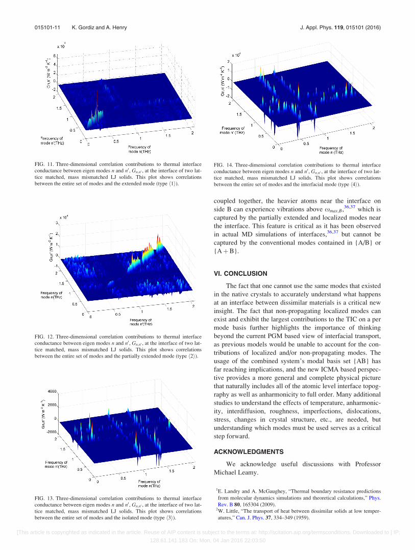
FIG. 11. Three-dimensional correlation contributions to thermal interface
conductance between eigen modes n and n0, Gn;n0 , at the interface of two lat-
tice matched, mass mismatched LJ solids. This plot shows correlations
between the entire set of modes and the extended mode (type h1i).
FIG. 12. Three-dimensional correlation contributions to thermal interface
conductance between eigen modes n and n0, Gn;n0 , at the interface of two lat-
tice matched, mass mismatched LJ solids. This plot shows correlations
between the entire set of modes and the partially extended mode (type h2i).
FIG. 13. Three-dimensional correlation contributions to thermal interface
conductance between eigen modes n and n0, Gn;n0 , at the interface of two lat-
tice matched, mass mismatched LJ solids. This plot shows correlations
between the entire set of modes and the isolated mode (type h3i).
FIG. 14. Three-dimensional correlation contributions to thermal interface
conductance between eigen modes n and n0, Gn;n0 , at the interface of two lat-
tice matched, mass mismatched LJ solids. This plot shows correlations
between the entire set of modes and the interfacial mode (type h4i).
015101-11 K. Gordiz and A. Henry J. Appl. Phys. 119, 015101 (2016)
[This article is copyrighted as indicated in the article. Reuse of AIP content is subject to the terms at: http://scitation.aip.org/termsconditions. Downloaded to ] IP:
128.61.141.183 On: Mon, 04 Jan 2016 22:03:50
3N. Mingo and L. Yang, “Phonon transport in nanowires coated with an
amorphous material: An atomistic Green’s function approach,” Phys. Rev.
B 68, 245406 (2003).4P. Schelling, S. Phillpot, and P. Keblinski, “Kapitza conductance and pho-
non scattering at grain boundaries by simulation,” J. Appl. Phys. 95,
6082–6091 (2004).5E. T. Swartz and R. O. Pohl, “Thermal boundary resistance,” Rev. Mod.
Phys. 61, 605 (1989).6W. Zhang, T. Fisher, and N. Mingo, “The atomistic Green’s function
method: An efficient simulation approach for nanoscale phonon transport,”
Numer. Heat Trans., Part B 51, 333–349 (2007).7N. Mingo, Thermal nanosystems and nanomaterials (Springer, 2009), pp.
63–94.8D. Broido, M. Malorny, G. Birner, N. Mingo, and D. Stewart, “Intrinsic
lattice thermal conductivity of semiconductors from first principles,”
Appl. Phys. Lett. 91, 231922 (2007).9J. Garg, N. Bonini, B. Kozinsky, and N. Marzari, “Role of disorder and
anharmonicity in the thermal conductivity of silicon-germanium alloys: A
first-principles study,” Phys. Rev. Lett. 106, 045901 (2011).10K. Gordiz and A. Henry, “A formalism for calculating the modal contribu-
tions to thermal interface conductance,” New J. Phys. 17, 103002 (2015).11J. Turney, A. McGaughey, and C. Amon, “Assessing the applicability of
quantum corrections to classical thermal conductivity predictions,” Phys.
Rev. B 79, 224305 (2009).12W. Lv and A. Henry, “Direct calculation of modal contributions to thermal
conductivity via green-kubo modal analysis: Crystalline and amorphous
silicon,” New J. Phys. (to be published).13M. T. Dove, Introduction to Lattice Dynamics (Cambridge University
Press, 1993), Vol. 4.14R. J. Hardy, “Energy-flux operator for a lattice,” Phys. Rev. 132, 168
(1963).15A. S. Henry and G. Chen, “Spectral phonon transport properties of silicon
based on molecular dynamics simulations and lattice dynamics,”
J. Comput. Theor. Nanosci. 5, 141–152 (2008).16Y. Chalopin, K. Esfarjani, A. Henry, S. Volz, and G. Chen, “Thermal
interface conductance in Si/Ge superlattices by equilibrium molecular
dynamics,” Phys. Rev. B 85, 195302 (2012).17G. Domingues, S. Volz, K. Joulain, and J.-J. Greffet, “Heat transfer
between two nanoparticles through near field interaction,” Phys. Rev. Lett.
94, 085901 (2005).18Z.-Y. Ong and E. Pop, “Frequency and polarization dependence of thermal
coupling between carbon nanotubes and SiO2,” J. Appl. Phys. 108, 103502
(2010).19R. Kubo, “The fluctuation-dissipation theorem,” Rep. Prog. Phys. 29, 255
(1966).20G. Chen, Nanoscale Energy Transport and Conversion: A Parallel
Treatment of Electrons, Molecules, Phonons, and Photons (Oxford
University Press, USA, 2005).
21C. H. Baker, D. A. Jordan, and P. M. Norris, “Application of the wavelet
transform to nanoscale thermal transport,” Phys. Rev. B 86, 104306
(2012).22P. K. Schelling, S. R. Phillpot, and P. Keblinski, “Phonon wave-packet dy-
namics at semiconductor interfaces by molecular-dynamics simulation,”
Appl. Phys. Lett. 80, 2484–2486 (2002).23N. A. Roberts and D. Walker, “Phonon wave-packet simulations of Ar/
Kr interfaces for thermal rectification,” J. Appl. Phys. 108, 123515
(2010).24W. Zhang, N. Mingo, and T. Fisher, “Simulation of interfacial phonon
transport in Si–Ge heterostructures using an atomistic Green’s function
method,” J. Heat Transfer 129, 483–491 (2007).25Z. Tian, K. Esfarjani, and G. Chen, “Enhancing phonon transmission
across a Si/Ge interface by atomic roughness: First-principles study with
the Green’s function method,” Phys. Rev. B 86, 235304 (2012).26H. Rafii-Tabar, Computational Physics of Carbon Nanotubes (Cambridge
University Press, 2008).27A. Rajabpour and S. Volz, “Thermal boundary resistance from mode
energy relaxation times: Case study of argon-like crystals by molecular
dynamics,” J. Appl. Phys. 108, 094324 (2010).28S. Sarkar and R. P. Selvam, “Molecular dynamics simulation of effective
thermal conductivity and study of enhanced thermal transport mechanism
in nanofluids,” J. Appl. Phys. 102, 074302 (2007).29K. Gordiz, D. J. Singh, and A. Henry, “Ensemble averaging vs. time aver-
aging in molecular dynamics simulations of thermal conductivity,”
J. Appl. Phys. 117, 045104 (2015).30J. Tersoff, “Modeling solid-state chemistry: Interatomic potentials for mul-
ticomponent systems,” Phys. Rev. B 39, 5566 (1989).31A. M. Kosevich, “Localization of vibrations near extended defects,” The
Crystal Lattice: Phonons, Solitons, Dislocations, Superlattices, 2nd ed.
(Wiley, 2006), Chap. 12, pp. 279–296.32P. E. Hopkins, P. M. Norris, and J. C. Duda, “Anharmonic phonon interac-
tions at interfaces and contributions to thermal boundary conductance,”
J. Heat Transfer 133, 062401 (2011).33J. V. Goicochea, M. Madrid, and C. Amon, “Thermal properties for bulk
silicon based on the determination of relaxation times using molecular
dynamics,” J. Heat Transfer 132, 012401 (2010).34A. Henry and G. Chen, “Anomalous heat conduction in polyethylene
chains: Theory and molecular dynamics simulations,” Phys. Rev. B 79,
144305 (2009).35A. Henry and G. Chen, “High thermal conductivity of single polyethylene
chains using molecular dynamics simulations,” Phys. Rev. Lett. 101,
235502 (2008).36S. Shin, M. Kaviany, T. Desai, and R. Bonner, “Roles of atomic restructur-
ing in interfacial phonon transport,” Phys. Rev. B 82, 081302 (2010).37N. Yang et al., “Thermal interface conductance between aluminum and sil-
icon by molecular dynamics simulations,” J. Comput. Theor. Nanosci 12,
168–174 (2015).
015101-12 K. Gordiz and A. Henry J. Appl. Phys. 119, 015101 (2016)
[This article is copyrighted as indicated in the article. Reuse of AIP content is subject to the terms at: http://scitation.aip.org/termsconditions. Downloaded to ] IP:
128.61.141.183 On: Mon, 04 Jan 2016 22:03:50