philips ob tracevue d.01.00 installation and service manual
TRANSCRIPT

Patient Monitoring
INSTALLATION AND SERVICE MANUAL
OB
Tra
ce
Vu
e
OB TraceVue
453564115251Software revision F.00.10Published in Germany 08.2008
Title

© Copyright 1996-2008 Koninklijke Philips Electronics N.V. 8081318
All rights reserved
NoticePhilips makes no warranty of any kind with regard to this material, including, but not limited to, the implied warranties of merchantability and fitness for a particular purpose. Philips shall not be liable for errors contained herein or for incidental or consequential damages in con-nection with the furnishing, performance or use of this material.
This document contains proprietary information that is protected by copyright. All rights are reserved. No part of this document may be photocopied, reproduced or translated to another language without prior written consent of Philips.
The information contained in this document is subject to change without notice.
Philips assumes no responsibility for the use or reliability of its software on equipment that is not furnished by Philips.
Federal Law (US) restricts this device to sale by or on the order of a physician.
Philips developed this system in cooperation with Massachusetts General Hospital, an affili-ate of the Harvard Medical School.
WarningFailure on the part of the responsible individual hospital or institution employing the use of this equipment to implement a satisfactory maintenance schedule may cause undue equipment failure and possible health hazards.
TrademarksMicrosoft® is a U.S. registered trademark of Microsoft Corp.Windows®, Windows NT®, Windows 2000®, Windows Server 2003®and Windows XP®are U.S. registered trademarks of Microsoft Corp.
All other product and company names mentioned may be the trademarks of their respective owners.
AcknowledgementsAutomated Windows installation developed using AutoIt.
http://www.hiddensoft.com/AutoIt/
OB TraceVue uses ZedGraph.

Printing History
Edition ................. Part Number .............. OB TraceVue Release................ Print Date
First Edition ......... M1381-9000J............. A.02.00 .................................... August 1999Second Edition..... M1381-9000K ........... B.00.00 ..................................... March 2000Third Edition........ M1381-9000L............ B.01.00 ...............................September 2000Fourth Edition...... M1381-9000M........... B.01.00 ..................................... March 2001Fifth Edition......... M1381-9000N ........... C.00.00 ......................................... July 2001Sixth Edition ........ M1381-9000P............ C.01.00 ...............................November 2001Seventh Edition.... M1381-9000Q ........... C.01.01 ..................................... March 2002Eighth Edition...... M1381-9000R ........... C.01.01 (new PC hardware) ...October 2002Ninth Edition ....... M1381-9000S............ D.00.00 ....................................... April 200310th Edition ......... M1381-9000T............ D.00.01 .................................... August 200311th Edition.......... M1381-9000U ........... D.00.02 ................................... January 200412th Edition ......... M1381-9000V ........... D.01.00 ......................................... July 200413th Edition ......... M1381-9000W .......... D.01.10 .................................... August 200414th Edition ......... M1381-9000X ........... D.01.11 ................................. February 200515th Edition ......... M1381-9000Y ........... D.01.13 ...............................September 200516th Edition ......... M1381-9000Z............ E.00.00.................................... January 200617th Edition ......... M1381-900AA .......... E.00.10...................................... March 200618th Edition ......... M1381-900AB........... E.00.20......................................... June 200619th Edition ......... M1381-900AC........... E.00.21................................ December 200620th Edition ......... M1381-900AD .......... E.00.22......................................... May 200721st Edition.......... M1381-900AE........... E.00.23 ...............................November 200722nd Edition ........453564115251.......... F.00.10 ..................................... August 2008


Contents-1
Contents
1. Overview . . . . . . . . . . . . . . . . . . . . . . . . . . . . . . . . . . . . . . . . . . . . . . . . . . . . . . . . . . . . . . . . . 1-1What is OB TraceVue? . . . . . . . . . . . . . . . . . . . . . . . . . . . . . . . . . . . . . . . . . . . . . . . . . . . . . . . . . 1Who Should Read This Manual . . . . . . . . . . . . . . . . . . . . . . . . . . . . . . . . . . . . . . . . . . . . . . . . . . . . 1About This Manual . . . . . . . . . . . . . . . . . . . . . . . . . . . . . . . . . . . . . . . . . . . . . . . . . . . . . . . . . . . . 1Special Tools . . . . . . . . . . . . . . . . . . . . . . . . . . . . . . . . . . . . . . . . . . . . . . . . . . . . . . . . . . . . . . . . 2Service Packs . . . . . . . . . . . . . . . . . . . . . . . . . . . . . . . . . . . . . . . . . . . . . . . . . . . . . . . . . . . . . . . . 2Conventions in This Guide . . . . . . . . . . . . . . . . . . . . . . . . . . . . . . . . . . . . . . . . . . . . . . . . . . . . . . . 3Sterilization and Cleaning . . . . . . . . . . . . . . . . . . . . . . . . . . . . . . . . . . . . . . . . . . . . . . . . . . . . . . . . 3
2. Safety . . . . . . . . . . . . . . . . . . . . . . . . . . . . . . . . . . . . . . . . . . . . . . . . . . . . . . . . . . . . . . . . . . . . 2-1Introduction . . . . . . . . . . . . . . . . . . . . . . . . . . . . . . . . . . . . . . . . . . . . . . . . . . . . . . . . . . . . . . . . . 1Symbol Identification. . . . . . . . . . . . . . . . . . . . . . . . . . . . . . . . . . . . . . . . . . . . . . . . . . . . . . . . . . . 1System Overview . . . . . . . . . . . . . . . . . . . . . . . . . . . . . . . . . . . . . . . . . . . . . . . . . . . . . . . . . . . . . 2
Centralized System . . . . . . . . . . . . . . . . . . . . . . . . . . . . . . . . . . . . . . . . . . . . . . . . . . . . . . . . . 2Decentralized System . . . . . . . . . . . . . . . . . . . . . . . . . . . . . . . . . . . . . . . . . . . . . . . . . . . . . . . 3Uninterruptible Power Supply (UPS) . . . . . . . . . . . . . . . . . . . . . . . . . . . . . . . . . . . . . . . . . . . . . 4PC Power Consumption . . . . . . . . . . . . . . . . . . . . . . . . . . . . . . . . . . . . . . . . . . . . . . . . . . . . . . 4
Safety Test, Verification, and Customer Acceptance Procedures. . . . . . . . . . . . . . . . . . . . . . . . . . . . . . . 5Test and Inspection Matrix . . . . . . . . . . . . . . . . . . . . . . . . . . . . . . . . . . . . . . . . . . . . . . . . . . . . . . . 6
Safety Test Procedures . . . . . . . . . . . . . . . . . . . . . . . . . . . . . . . . . . . . . . . . . . . . . . . . . . . . . . 11When to Perform Test Procedures . . . . . . . . . . . . . . . . . . . . . . . . . . . . . . . . . . . . . . . . . . . . . . 16
Safety and Site Preparation . . . . . . . . . . . . . . . . . . . . . . . . . . . . . . . . . . . . . . . . . . . . . . . . . . . . . . 17Safety Notes for Cabling and Installation . . . . . . . . . . . . . . . . . . . . . . . . . . . . . . . . . . . . . . . . . . . . . 17Network Verification . . . . . . . . . . . . . . . . . . . . . . . . . . . . . . . . . . . . . . . . . . . . . . . . . . . . . . . . . . 17Electrostatic Handling Precautions . . . . . . . . . . . . . . . . . . . . . . . . . . . . . . . . . . . . . . . . . . . . . . . . 18Emissions and Immunity . . . . . . . . . . . . . . . . . . . . . . . . . . . . . . . . . . . . . . . . . . . . . . . . . . . . . . . 18
Guidance and Manufacturer’s Declaration . . . . . . . . . . . . . . . . . . . . . . . . . . . . . . . . . . . . . . . . . 18Recommended Separation Distances . . . . . . . . . . . . . . . . . . . . . . . . . . . . . . . . . . . . . . . . . . . . . 22
3. Security . . . . . . . . . . . . . . . . . . . . . . . . . . . . . . . . . . . . . . . . . . . . . . . . . . . . . . . . . . . . . . . . . . 3-1Introduction . . . . . . . . . . . . . . . . . . . . . . . . . . . . . . . . . . . . . . . . . . . . . . . . . . . . . . . . . . . . . . . . 1
OB TraceVue Security . . . . . . . . . . . . . . . . . . . . . . . . . . . . . . . . . . . . . . . . . . . . . . . . . . . . . . 1Operating System Security . . . . . . . . . . . . . . . . . . . . . . . . . . . . . . . . . . . . . . . . . . . . . . . . . . . . 1General Security Rules. . . . . . . . . . . . . . . . . . . . . . . . . . . . . . . . . . . . . . . . . . . . . . . . . . . . . . . 1Password Security . . . . . . . . . . . . . . . . . . . . . . . . . . . . . . . . . . . . . . . . . . . . . . . . . . . . . . . . . . 1
Windows Security . . . . . . . . . . . . . . . . . . . . . . . . . . . . . . . . . . . . . . . . . . . . . . . . . . . . . . . . . . . . . 2Installation / Configuration of MS Firewall . . . . . . . . . . . . . . . . . . . . . . . . . . . . . . . . . . . . . . . . . 2Windows User Groups . . . . . . . . . . . . . . . . . . . . . . . . . . . . . . . . . . . . . . . . . . . . . . . . . . . . . . . 2Windows Users . . . . . . . . . . . . . . . . . . . . . . . . . . . . . . . . . . . . . . . . . . . . . . . . . . . . . . . . . . . 2Access Rights. . . . . . . . . . . . . . . . . . . . . . . . . . . . . . . . . . . . . . . . . . . . . . . . . . . . . . . . . . . . . 4Interrupting Auto Login . . . . . . . . . . . . . . . . . . . . . . . . . . . . . . . . . . . . . . . . . . . . . . . . . . . . . . 7Log On As Windows Administrator . . . . . . . . . . . . . . . . . . . . . . . . . . . . . . . . . . . . . . . . . . . . . . 7Modifying Access Rights . . . . . . . . . . . . . . . . . . . . . . . . . . . . . . . . . . . . . . . . . . . . . . . . . . . . . 7
4. System Description. . . . . . . . . . . . . . . . . . . . . . . . . . . . . . . . . . . . . . . . . . . . . . . . . . . . . . . . . 4-1Overview. . . . . . . . . . . . . . . . . . . . . . . . . . . . . . . . . . . . . . . . . . . . . . . . . . . . . . . . . . . . . . . . . . . 1Centralized Implementation . . . . . . . . . . . . . . . . . . . . . . . . . . . . . . . . . . . . . . . . . . . . . . . . . . . . . . 2Decentralized Implementation . . . . . . . . . . . . . . . . . . . . . . . . . . . . . . . . . . . . . . . . . . . . . . . . . . . . 2Shipment Status . . . . . . . . . . . . . . . . . . . . . . . . . . . . . . . . . . . . . . . . . . . . . . . . . . . . . . . . . . . . . . 3Hardware . . . . . . . . . . . . . . . . . . . . . . . . . . . . . . . . . . . . . . . . . . . . . . . . . . . . . . . . . . . . . . . . . . 4
Contents

Contents-2
PCs/Memory . . . . . . . . . . . . . . . . . . . . . . . . . . . . . . . . . . . . . . . . . . . . . . . . . . . . . . . . . . . . . 4Optical Disk Drives and Medium Changers . . . . . . . . . . . . . . . . . . . . . . . . . . . . . . . . . . . . . . . . . 5Displays . . . . . . . . . . . . . . . . . . . . . . . . . . . . . . . . . . . . . . . . . . . . . . . . . . . . . . . . . . . . . . . . 5
Software Components . . . . . . . . . . . . . . . . . . . . . . . . . . . . . . . . . . . . . . . . . . . . . . . . . . . . . . . . . . 6OB TraceVue . . . . . . . . . . . . . . . . . . . . . . . . . . . . . . . . . . . . . . . . . . . . . . . . . . . . . . . . . . . . 6Third Party Software . . . . . . . . . . . . . . . . . . . . . . . . . . . . . . . . . . . . . . . . . . . . . . . . . . . . . . . . 6
Wall Cabling and Faceplates . . . . . . . . . . . . . . . . . . . . . . . . . . . . . . . . . . . . . . . . . . . . . . . . . . . . . 7System Limitations . . . . . . . . . . . . . . . . . . . . . . . . . . . . . . . . . . . . . . . . . . . . . . . . . . . . . . . . . . . . 8
Power . . . . . . . . . . . . . . . . . . . . . . . . . . . . . . . . . . . . . . . . . . . . . . . . . . . . . . . . . . . . . . . . . . 8PCs and Fetal Monitors . . . . . . . . . . . . . . . . . . . . . . . . . . . . . . . . . . . . . . . . . . . . . . . . . . . . . . 8Serial Port Servers . . . . . . . . . . . . . . . . . . . . . . . . . . . . . . . . . . . . . . . . . . . . . . . . . . . . . . . . . . 9Modems . . . . . . . . . . . . . . . . . . . . . . . . . . . . . . . . . . . . . . . . . . . . . . . . . . . . . . . . . . . . . . . . 9Interfacing . . . . . . . . . . . . . . . . . . . . . . . . . . . . . . . . . . . . . . . . . . . . . . . . . . . . . . . . . . . . . . 10Network . . . . . . . . . . . . . . . . . . . . . . . . . . . . . . . . . . . . . . . . . . . . . . . . . . . . . . . . . . . . . . . 10
Documentation . . . . . . . . . . . . . . . . . . . . . . . . . . . . . . . . . . . . . . . . . . . . . . . . . . . . . . . . . . . . . . 11
5. New System Setup . . . . . . . . . . . . . . . . . . . . . . . . . . . . . . . . . . . . . . . . . . . . . . . . . . . . . . . . .5-1Introduction . . . . . . . . . . . . . . . . . . . . . . . . . . . . . . . . . . . . . . . . . . . . . . . . . . . . . . . . . . . . . . . . . 1
PC Types . . . . . . . . . . . . . . . . . . . . . . . . . . . . . . . . . . . . . . . . . . . . . . . . . . . . . . . . . . . . . . . . 1Order in which to Perform Tasks . . . . . . . . . . . . . . . . . . . . . . . . . . . . . . . . . . . . . . . . . . . . . . . . 1
Installation Checklists . . . . . . . . . . . . . . . . . . . . . . . . . . . . . . . . . . . . . . . . . . . . . . . . . . . . . . . . . . 2Tasks . . . . . . . . . . . . . . . . . . . . . . . . . . . . . . . . . . . . . . . . . . . . . . . . . . . . . . . . . . . . . . . . . . . . 17WEB Clients . . . . . . . . . . . . . . . . . . . . . . . . . . . . . . . . . . . . . . . . . . . . . . . . . . . . . . . . . . . . . . . 40
Starting a WEB Client . . . . . . . . . . . . . . . . . . . . . . . . . . . . . . . . . . . . . . . . . . . . . . . . . . . . . . 40Real-Time WEB Client . . . . . . . . . . . . . . . . . . . . . . . . . . . . . . . . . . . . . . . . . . . . . . . . . . . . . 40MS Vista for WEB TS Clients . . . . . . . . . . . . . . . . . . . . . . . . . . . . . . . . . . . . . . . . . . . . . . . . . 40Restrictions/Requirements. . . . . . . . . . . . . . . . . . . . . . . . . . . . . . . . . . . . . . . . . . . . . . . . . . . . 41Manually Installing ActiveX Control of OB TraceVue Web Client . . . . . . . . . . . . . . . . . . . . . . . . . 42Installing OB TraceVue Real Time Alarming Software Without Connecting to Terminal Server. . . . . . 42
6. Setup Details . . . . . . . . . . . . . . . . . . . . . . . . . . . . . . . . . . . . . . . . . . . . . . . . . . . . . . . . . . . . . .6-1Introduction . . . . . . . . . . . . . . . . . . . . . . . . . . . . . . . . . . . . . . . . . . . . . . . . . . . . . . . . . . . . . . . . . 1Installing a Client on a Cart (Mobile Client) . . . . . . . . . . . . . . . . . . . . . . . . . . . . . . . . . . . . . . . . . . . . 1
Telemetry Unit . . . . . . . . . . . . . . . . . . . . . . . . . . . . . . . . . . . . . . . . . . . . . . . . . . . . . . . . . . . 1Client UPS . . . . . . . . . . . . . . . . . . . . . . . . . . . . . . . . . . . . . . . . . . . . . . . . . . . . . . . . . . . . . . . 2Configuration . . . . . . . . . . . . . . . . . . . . . . . . . . . . . . . . . . . . . . . . . . . . . . . . . . . . . . . . . . . . . 2Moving the Cart . . . . . . . . . . . . . . . . . . . . . . . . . . . . . . . . . . . . . . . . . . . . . . . . . . . . . . . . . . 2
Connecting Fetal Monitors . . . . . . . . . . . . . . . . . . . . . . . . . . . . . . . . . . . . . . . . . . . . . . . . . . . . . . . 3M1350, M1351/53 and Avalon FM20/FM30/40/50 Monitors. . . . . . . . . . . . . . . . . . . . . . . . . . . . . . 3Other Fetal Monitors . . . . . . . . . . . . . . . . . . . . . . . . . . . . . . . . . . . . . . . . . . . . . . . . . . . . . . . . 3Network Type. . . . . . . . . . . . . . . . . . . . . . . . . . . . . . . . . . . . . . . . . . . . . . . . . . . . . . . . . . . . . 3Connecting Four Fetal Monitors . . . . . . . . . . . . . . . . . . . . . . . . . . . . . . . . . . . . . . . . . . . . . . . . 4Connecting More than Four Fetal Monitors . . . . . . . . . . . . . . . . . . . . . . . . . . . . . . . . . . . . . . . . . 4Protocol Conversion . . . . . . . . . . . . . . . . . . . . . . . . . . . . . . . . . . . . . . . . . . . . . . . . . . . . . . . . 4Hewlett-Packard / Agilent / Philips Fetal Monitors. . . . . . . . . . . . . . . . . . . . . . . . . . . . . . . . . . . . . 5
Connecting to the Network . . . . . . . . . . . . . . . . . . . . . . . . . . . . . . . . . . . . . . . . . . . . . . . . . . . . . . . 8Network Connections. . . . . . . . . . . . . . . . . . . . . . . . . . . . . . . . . . . . . . . . . . . . . . . . . . . . . . . . 8Switches . . . . . . . . . . . . . . . . . . . . . . . . . . . . . . . . . . . . . . . . . . . . . . . . . . . . . . . . . . . . . . . . 8Network Specifications. . . . . . . . . . . . . . . . . . . . . . . . . . . . . . . . . . . . . . . . . . . . . . . . . . . . . . . 8Cable Specifications . . . . . . . . . . . . . . . . . . . . . . . . . . . . . . . . . . . . . . . . . . . . . . . . . . . . . . . . 9

Contents-3
Cabling a LAN . . . . . . . . . . . . . . . . . . . . . . . . . . . . . . . . . . . . . . . . . . . . . . . . . . . . . . . 10Installing and Configuring Remote LAN Clients . . . . . . . . . . . . . . . . . . . . . . . . . . . . . . . . . . . . . . . . 11
Limitations and Prerequisites. . . . . . . . . . . . . . . . . . . . . . . . . . . . . . . . . . . . . . . . . . . . . . . . . . 11Installation and Configuration . . . . . . . . . . . . . . . . . . . . . . . . . . . . . . . . . . . . . . . . . . . . . . . . . 11
Installing and Setting up a Serial Port Server . . . . . . . . . . . . . . . . . . . . . . . . . . . . . . . . . . . . . . . . . . 13Introduction . . . . . . . . . . . . . . . . . . . . . . . . . . . . . . . . . . . . . . . . . . . . . . . . . . . . . . . . . . . . . 13Host PC Network Settings . . . . . . . . . . . . . . . . . . . . . . . . . . . . . . . . . . . . . . . . . . . . . . . . . . . 15Connect Port Server. . . . . . . . . . . . . . . . . . . . . . . . . . . . . . . . . . . . . . . . . . . . . . . . . . . . . . . . 16Port Server Network Settings. . . . . . . . . . . . . . . . . . . . . . . . . . . . . . . . . . . . . . . . . . . . . . . . . . 17Install Software . . . . . . . . . . . . . . . . . . . . . . . . . . . . . . . . . . . . . . . . . . . . . . . . . . . . . . . . . . 19Configure Serial Port Server . . . . . . . . . . . . . . . . . . . . . . . . . . . . . . . . . . . . . . . . . . . . . . . . . . 21Configure OB TraceVue . . . . . . . . . . . . . . . . . . . . . . . . . . . . . . . . . . . . . . . . . . . . . . . . . . . . 26Connect Fetal Monitors . . . . . . . . . . . . . . . . . . . . . . . . . . . . . . . . . . . . . . . . . . . . . . . . . . . . . 26Check Fetal Monitor to Bed Connection . . . . . . . . . . . . . . . . . . . . . . . . . . . . . . . . . . . . . . . . . . 26Using the Serial Port Server at a Different PC. . . . . . . . . . . . . . . . . . . . . . . . . . . . . . . . . . . . . . . 27Replacing a Serial Port Server . . . . . . . . . . . . . . . . . . . . . . . . . . . . . . . . . . . . . . . . . . . . . . . . . 27
Setting Up a Printer . . . . . . . . . . . . . . . . . . . . . . . . . . . . . . . . . . . . . . . . . . . . . . . . . . . . . . . . . . . 33Windows Printer Types . . . . . . . . . . . . . . . . . . . . . . . . . . . . . . . . . . . . . . . . . . . . . . . . . . . . . 33General Printer Setup Procedures . . . . . . . . . . . . . . . . . . . . . . . . . . . . . . . . . . . . . . . . . . . . . . . 34Printer Connected to a PC’s Parallel Port . . . . . . . . . . . . . . . . . . . . . . . . . . . . . . . . . . . . . . . . . . 36Printer Connected to the Network using a HP JetDirect Card . . . . . . . . . . . . . . . . . . . . . . . . . . . . . 37
Setting Up Remote Connectivity . . . . . . . . . . . . . . . . . . . . . . . . . . . . . . . . . . . . . . . . . . . . . . . . . . 38Setting up Remote Trace Transmission . . . . . . . . . . . . . . . . . . . . . . . . . . . . . . . . . . . . . . . . . . . 38Setting up Web Access Through Dial-Up Modem . . . . . . . . . . . . . . . . . . . . . . . . . . . . . . . . . . . . 38Setting up Remote Access Support . . . . . . . . . . . . . . . . . . . . . . . . . . . . . . . . . . . . . . . . . . . . . . 38Setting Up Fax Transmission. . . . . . . . . . . . . . . . . . . . . . . . . . . . . . . . . . . . . . . . . . . . . . . . . . 39Installing a Modem . . . . . . . . . . . . . . . . . . . . . . . . . . . . . . . . . . . . . . . . . . . . . . . . . . . . . . . . 40
Installing and Configuring Microsoft Office 2007 . . . . . . . . . . . . . . . . . . . . . . . . . . . . . . . . . . . . . . . 42Installing Microsoft Office Small Business 2007 . . . . . . . . . . . . . . . . . . . . . . . . . . . . . . . . . . . . . 42Manual Installation . . . . . . . . . . . . . . . . . . . . . . . . . . . . . . . . . . . . . . . . . . . . . . . . . . . . . . . . 42Final Tasks . . . . . . . . . . . . . . . . . . . . . . . . . . . . . . . . . . . . . . . . . . . . . . . . . . . . . . . . . . . . . 43Installation Tasks . . . . . . . . . . . . . . . . . . . . . . . . . . . . . . . . . . . . . . . . . . . . . . . . . . . . . . . . . 43Checking Microsoft Office Version . . . . . . . . . . . . . . . . . . . . . . . . . . . . . . . . . . . . . . . . . . . . . 44Check for Publisher's Certificate Revocation List . . . . . . . . . . . . . . . . . . . . . . . . . . . . . . . . . . . . 44Troubleshooting . . . . . . . . . . . . . . . . . . . . . . . . . . . . . . . . . . . . . . . . . . . . . . . . . . . . . . . . . . 44Check .NET Programmability Support . . . . . . . . . . . . . . . . . . . . . . . . . . . . . . . . . . . . . . . . . . . 44Install .NET Programmability Support . . . . . . . . . . . . . . . . . . . . . . . . . . . . . . . . . . . . . . . . . . . 45
Installing Word and Excel Templates . . . . . . . . . . . . . . . . . . . . . . . . . . . . . . . . . . . . . . . . . . . . . . . 46Overview. . . . . . . . . . . . . . . . . . . . . . . . . . . . . . . . . . . . . . . . . . . . . . . . . . . . . . . . . . . . . . . 46New Installation . . . . . . . . . . . . . . . . . . . . . . . . . . . . . . . . . . . . . . . . . . . . . . . . . . . . . . . . . . 48
Installing the CareVue Integration Engine (CIE) . . . . . . . . . . . . . . . . . . . . . . . . . . . . . . . . . . . . . . . . 49HL7 Mapping Defaults. . . . . . . . . . . . . . . . . . . . . . . . . . . . . . . . . . . . . . . . . . . . . . . . . . . . . . 49
7. High Availability Server . . . . . . . . . . . . . . . . . . . . . . . . . . . . . . . . . . . . . . . . . . . . . . . . . . . . 7-1Introduction . . . . . . . . . . . . . . . . . . . . . . . . . . . . . . . . . . . . . . . . . . . . . . . . . . . . . . . . . . . . . . . . . 1
Directory Path for HA System . . . . . . . . . . . . . . . . . . . . . . . . . . . . . . . . . . . . . . . . . . . . . . . . . . 1Upgrading From Standard/High-end Internal Server to High Availability Server Pair . . . . . . . . . . . . . . . . . 2
Prepare Old Internal Server . . . . . . . . . . . . . . . . . . . . . . . . . . . . . . . . . . . . . . . . . . . . . . . . . . . . 2Prepare Existing ML350G4/G4p or ML350 G5 Hardware. . . . . . . . . . . . . . . . . . . . . . . . . . . . . . . . 2
Installing EMC Autostart . . . . . . . . . . . . . . . . . . . . . . . . . . . . . . . . . . . . . . . . . . . . . . . . . . . . . . . . 4New Setup and Upgrade from Existing Database. . . . . . . . . . . . . . . . . . . . . . . . . . . . . . . . . . . . . . 4

Contents-4
EMC Autostart Installation Record . . . . . . . . . . . . . . . . . . . . . . . . . . . . . . . . . . . . . . . . . . . . . . . 6Steps for Installation HA Server Pair. . . . . . . . . . . . . . . . . . . . . . . . . . . . . . . . . . . . . . . . . . . . . . 9
EMC Autostart High Availability User Interface . . . . . . . . . . . . . . . . . . . . . . . . . . . . . . . . . . . . . . . . 17Starting OB TraceVue . . . . . . . . . . . . . . . . . . . . . . . . . . . . . . . . . . . . . . . . . . . . . . . . . . . . . . . . . 19
Startup . . . . . . . . . . . . . . . . . . . . . . . . . . . . . . . . . . . . . . . . . . . . . . . . . . . . . . . . . . . . . . . . 19Shutting Down and Restarting OB TraceVue . . . . . . . . . . . . . . . . . . . . . . . . . . . . . . . . . . . . . . . . . . 19
Shutdown . . . . . . . . . . . . . . . . . . . . . . . . . . . . . . . . . . . . . . . . . . . . . . . . . . . . . . . . . . . . . . 19Restart . . . . . . . . . . . . . . . . . . . . . . . . . . . . . . . . . . . . . . . . . . . . . . . . . . . . . . . . . . . . . . . . 19
OB TraceVue SW-upgrade at HA-pair . . . . . . . . . . . . . . . . . . . . . . . . . . . . . . . . . . . . . . . . . . . . . . 20Preparing for Upgrading . . . . . . . . . . . . . . . . . . . . . . . . . . . . . . . . . . . . . . . . . . . . . . . . . . . . . 20OS/EMC Upgrade . . . . . . . . . . . . . . . . . . . . . . . . . . . . . . . . . . . . . . . . . . . . . . . . . . . . . . . . . 20OB TraceVue Upgrade . . . . . . . . . . . . . . . . . . . . . . . . . . . . . . . . . . . . . . . . . . . . . . . . . . . . . . 21Testing the HA System. . . . . . . . . . . . . . . . . . . . . . . . . . . . . . . . . . . . . . . . . . . . . . . . . . . . . . 22
Maintenance. . . . . . . . . . . . . . . . . . . . . . . . . . . . . . . . . . . . . . . . . . . . . . . . . . . . . . . . . . . . . . . . 23Performing a Manual Failover . . . . . . . . . . . . . . . . . . . . . . . . . . . . . . . . . . . . . . . . . . . . . . . . . 23Monitoring the Domain Daily . . . . . . . . . . . . . . . . . . . . . . . . . . . . . . . . . . . . . . . . . . . . . . . . . 23Maintenance on the Passive Server . . . . . . . . . . . . . . . . . . . . . . . . . . . . . . . . . . . . . . . . . . . . . . 23Switching Node Failure Detection to Point-to-point . . . . . . . . . . . . . . . . . . . . . . . . . . . . . . . . . . . 23Creating an Offline Backup . . . . . . . . . . . . . . . . . . . . . . . . . . . . . . . . . . . . . . . . . . . . . . . . . . . 24Restoring a TV Backup . . . . . . . . . . . . . . . . . . . . . . . . . . . . . . . . . . . . . . . . . . . . . . . . . . . . . 24Installation Test . . . . . . . . . . . . . . . . . . . . . . . . . . . . . . . . . . . . . . . . . . . . . . . . . . . . . . . . . . 25Changing the System Time . . . . . . . . . . . . . . . . . . . . . . . . . . . . . . . . . . . . . . . . . . . . . . . . . . . 25
EMC Autostart Server Recovery . . . . . . . . . . . . . . . . . . . . . . . . . . . . . . . . . . . . . . . . . . . . . . . . . . 26Changing the Default OB TraceVue User at an HA System . . . . . . . . . . . . . . . . . . . . . . . . . . . . . . . . . 36
Changing Only Administrator Default Password . . . . . . . . . . . . . . . . . . . . . . . . . . . . . . . . . . . . . 37Domain Integration of the HA Server . . . . . . . . . . . . . . . . . . . . . . . . . . . . . . . . . . . . . . . . . . . . . . . 38
Health Status Icon Display . . . . . . . . . . . . . . . . . . . . . . . . . . . . . . . . . . . . . . . . . . . . . . . . . . . 39
8. Network Based Storage . . . . . . . . . . . . . . . . . . . . . . . . . . . . . . . . . . . . . . . . . . . . . . . . . . . . .8-1Introduction . . . . . . . . . . . . . . . . . . . . . . . . . . . . . . . . . . . . . . . . . . . . . . . . . . . . . . . . . . . . . . . . . 1
Local Storage Directory . . . . . . . . . . . . . . . . . . . . . . . . . . . . . . . . . . . . . . . . . . . . . . . . . . . . . . 2Location of the Network Based Storage . . . . . . . . . . . . . . . . . . . . . . . . . . . . . . . . . . . . . . . . . . . . 2Integration Testing . . . . . . . . . . . . . . . . . . . . . . . . . . . . . . . . . . . . . . . . . . . . . . . . . . . . . . . . . 2
9. Troubleshooting . . . . . . . . . . . . . . . . . . . . . . . . . . . . . . . . . . . . . . . . . . . . . . . . . . . . . . . . . . .9-1Networking and System Setup Problems . . . . . . . . . . . . . . . . . . . . . . . . . . . . . . . . . . . . . . . . . . . . . . 1Network Storage Access . . . . . . . . . . . . . . . . . . . . . . . . . . . . . . . . . . . . . . . . . . . . . . . . . . . . . . . . . 4Hardware Problems . . . . . . . . . . . . . . . . . . . . . . . . . . . . . . . . . . . . . . . . . . . . . . . . . . . . . . . . . . . . 5Fetal Monitor Connection / Data Acquisition Problems. . . . . . . . . . . . . . . . . . . . . . . . . . . . . . . . . . . . . 6Application Problems. . . . . . . . . . . . . . . . . . . . . . . . . . . . . . . . . . . . . . . . . . . . . . . . . . . . . . . . . . . 7Troubleshooting the Removable Storage Manager . . . . . . . . . . . . . . . . . . . . . . . . . . . . . . . . . . . . . . . . 8
10. Maintenance . . . . . . . . . . . . . . . . . . . . . . . . . . . . . . . . . . . . . . . . . . . . . . . . . . . . . . . . . . . .10-1Introduction . . . . . . . . . . . . . . . . . . . . . . . . . . . . . . . . . . . . . . . . . . . . . . . . . . . . . . . . . . . . . . . . . 1Recommended Maintenance . . . . . . . . . . . . . . . . . . . . . . . . . . . . . . . . . . . . . . . . . . . . . . . . . . . . . . 1Caring for Optical Drives and Media. . . . . . . . . . . . . . . . . . . . . . . . . . . . . . . . . . . . . . . . . . . . . . . . . 2
Caring for Optical Drives (standalone drives only). . . . . . . . . . . . . . . . . . . . . . . . . . . . . . . . . . . . . 2Caring for Optical Disks . . . . . . . . . . . . . . . . . . . . . . . . . . . . . . . . . . . . . . . . . . . . . . . . . . . . . . 2
Rebooting the WEB/Terminal Server . . . . . . . . . . . . . . . . . . . . . . . . . . . . . . . . . . . . . . . . . . . . . . . . 3Virus Protection . . . . . . . . . . . . . . . . . . . . . . . . . . . . . . . . . . . . . . . . . . . . . . . . . . . . . . . . . . . . . . 3

Contents-5
External Database Performance . . . . . . . . . . . . . . . . . . . . . . . . . . . . . . . . . . . . . . . . . . . . . . . . . . . . 4
11. System Support . . . . . . . . . . . . . . . . . . . . . . . . . . . . . . . . . . . . . . . . . . . . . . . . . . . . . . . . . 11-1Overview. . . . . . . . . . . . . . . . . . . . . . . . . . . . . . . . . . . . . . . . . . . . . . . . . . . . . . . . . . . . . . . . . . . 1System Overview Tool. . . . . . . . . . . . . . . . . . . . . . . . . . . . . . . . . . . . . . . . . . . . . . . . . . . . . . . . . . 2
Restrictions . . . . . . . . . . . . . . . . . . . . . . . . . . . . . . . . . . . . . . . . . . . . . . . . . . . . . . . . . . . . . . 2Using with OB TraceVue Remote LAN Clients / HA Server Pair . . . . . . . . . . . . . . . . . . . . . . . . . . 2
Remote Support Using Remote Desktop . . . . . . . . . . . . . . . . . . . . . . . . . . . . . . . . . . . . . . . . . . . . . . 3Overview. . . . . . . . . . . . . . . . . . . . . . . . . . . . . . . . . . . . . . . . . . . . . . . . . . . . . . . . . . . . . . . . 3Enabling Terminal Services Server Remote Support on a Server PC . . . . . . . . . . . . . . . . . . . . . . . . . 4Modem Setup . . . . . . . . . . . . . . . . . . . . . . . . . . . . . . . . . . . . . . . . . . . . . . . . . . . . . . . . . . . . . 4Installing Terminal Services Client . . . . . . . . . . . . . . . . . . . . . . . . . . . . . . . . . . . . . . . . . . . . . . . 5Using Terminal Services Client . . . . . . . . . . . . . . . . . . . . . . . . . . . . . . . . . . . . . . . . . . . . . . . . . 6
Log Files . . . . . . . . . . . . . . . . . . . . . . . . . . . . . . . . . . . . . . . . . . . . . . . . . . . . . . . . . . . . . . . . . . . 7HP / Compaq Insight Management Software . . . . . . . . . . . . . . . . . . . . . . . . . . . . . . . . . . . . . . . . . . . 9
Introduction . . . . . . . . . . . . . . . . . . . . . . . . . . . . . . . . . . . . . . . . . . . . . . . . . . . . . . . . . . . . . . 9Management Agents . . . . . . . . . . . . . . . . . . . . . . . . . . . . . . . . . . . . . . . . . . . . . . . . . . . . . . . . 9HP / Compaq Insight Manager. . . . . . . . . . . . . . . . . . . . . . . . . . . . . . . . . . . . . . . . . . . . . . . . . . 9HP Insight Diagnostics Online Edition for Windows . . . . . . . . . . . . . . . . . . . . . . . . . . . . . . . . . . 10
12. Configuration Verification Procedure . . . . . . . . . . . . . . . . . . . . . . . . . . . . . . . . . . . . . . . 12-1Customer Verification . . . . . . . . . . . . . . . . . . . . . . . . . . . . . . . . . . . . . . . . . . . . . . . . . . . . . . . . . . 1Configuration Verification . . . . . . . . . . . . . . . . . . . . . . . . . . . . . . . . . . . . . . . . . . . . . . . . . . . . . . . 1
13. Component Installation (Upgrade/Repair) . . . . . . . . . . . . . . . . . . . . . . . . . . . . . . . . . . . 13-1Introduction . . . . . . . . . . . . . . . . . . . . . . . . . . . . . . . . . . . . . . . . . . . . . . . . . . . . . . . . . . . . . . . . . 1Software Distribution. . . . . . . . . . . . . . . . . . . . . . . . . . . . . . . . . . . . . . . . . . . . . . . . . . . . . . . . . . . 1PC System Board Replacement . . . . . . . . . . . . . . . . . . . . . . . . . . . . . . . . . . . . . . . . . . . . . . . . . . . . 2Additional Memory . . . . . . . . . . . . . . . . . . . . . . . . . . . . . . . . . . . . . . . . . . . . . . . . . . . . . . . . . . . 2Network Interface (LAN) Card . . . . . . . . . . . . . . . . . . . . . . . . . . . . . . . . . . . . . . . . . . . . . . . . . . . . 3PCI RS-232 Serial I/F Card . . . . . . . . . . . . . . . . . . . . . . . . . . . . . . . . . . . . . . . . . . . . . . . . . . . . . . . 3
Fitting the PCI RS-232 Serial Interface Card . . . . . . . . . . . . . . . . . . . . . . . . . . . . . . . . . . . . . . . . 3Using FMSpy to Test the COM Ports . . . . . . . . . . . . . . . . . . . . . . . . . . . . . . . . . . . . . . . . . . . . . 4
CD-ROM Drive . . . . . . . . . . . . . . . . . . . . . . . . . . . . . . . . . . . . . . . . . . . . . . . . . . . . . . . . . . . . . . 5Primary Hard Disk Drive . . . . . . . . . . . . . . . . . . . . . . . . . . . . . . . . . . . . . . . . . . . . . . . . . . . . . . . . 5SCSI Host Adapter . . . . . . . . . . . . . . . . . . . . . . . . . . . . . . . . . . . . . . . . . . . . . . . . . . . . . . . . . . . . 6
Host Adapter Types . . . . . . . . . . . . . . . . . . . . . . . . . . . . . . . . . . . . . . . . . . . . . . . . . . . . . . . . . 6Slot Assignment . . . . . . . . . . . . . . . . . . . . . . . . . . . . . . . . . . . . . . . . . . . . . . . . . . . . . . . . . . . 6SCSI BIOS . . . . . . . . . . . . . . . . . . . . . . . . . . . . . . . . . . . . . . . . . . . . . . . . . . . . . . . . . . . . . . 6
Secondary Hard Disk Drive (for Storage Systems). . . . . . . . . . . . . . . . . . . . . . . . . . . . . . . . . . . . . . . . 7Disk Installation . . . . . . . . . . . . . . . . . . . . . . . . . . . . . . . . . . . . . . . . . . . . . . . . . . . . . . . . . . . 7Windows Installation . . . . . . . . . . . . . . . . . . . . . . . . . . . . . . . . . . . . . . . . . . . . . . . . . . . . . . . . 7
Optical Drives . . . . . . . . . . . . . . . . . . . . . . . . . . . . . . . . . . . . . . . . . . . . . . . . . . . . . . . . . . . . . . . 9Optical Medium Changers (Autochanger/Jukebox) . . . . . . . . . . . . . . . . . . . . . . . . . . . . . . . . . . . . . . 11Configure Removable Storage Manager (RSM) for Archiving . . . . . . . . . . . . . . . . . . . . . . . . . . . . . . . 14
General Configuration . . . . . . . . . . . . . . . . . . . . . . . . . . . . . . . . . . . . . . . . . . . . . . . . . . . . . . 14Configuration of RSM for Plasmon and HP Jukeboxes . . . . . . . . . . . . . . . . . . . . . . . . . . . . . . . . . 14Configuration of RSM for Plasmon and HP Standalone MO Drives . . . . . . . . . . . . . . . . . . . . . . . . 14Enabling/Disabling Drives . . . . . . . . . . . . . . . . . . . . . . . . . . . . . . . . . . . . . . . . . . . . . . . . . . . 14
Supported Archiving Device Combinations . . . . . . . . . . . . . . . . . . . . . . . . . . . . . . . . . . . . . . . . . . . 15

Contents-6
Optical Disk Drive Cabinet . . . . . . . . . . . . . . . . . . . . . . . . . . . . . . . . . . . . . . . . . . . . . . . . . . . . . . 17Before Installing the Optical Disk Drive Cabinet . . . . . . . . . . . . . . . . . . . . . . . . . . . . . . . . . . . . . 17Installing the Optical Disk Drive Cabinet . . . . . . . . . . . . . . . . . . . . . . . . . . . . . . . . . . . . . . . . . . 18Maintenance. . . . . . . . . . . . . . . . . . . . . . . . . . . . . . . . . . . . . . . . . . . . . . . . . . . . . . . . . . . . . 18Repair . . . . . . . . . . . . . . . . . . . . . . . . . . . . . . . . . . . . . . . . . . . . . . . . . . . . . . . . . . . . . . . . . 18
Backup Device (External Server Only) . . . . . . . . . . . . . . . . . . . . . . . . . . . . . . . . . . . . . . . . . . . . . . 19High-End External Server (RAID) . . . . . . . . . . . . . . . . . . . . . . . . . . . . . . . . . . . . . . . . . . . . . . 19SCSI Connectors for High-end External Backup Devices . . . . . . . . . . . . . . . . . . . . . . . . . . . . . . . 19Standard External Server . . . . . . . . . . . . . . . . . . . . . . . . . . . . . . . . . . . . . . . . . . . . . . . . . . . . 20
UPS . . . . . . . . . . . . . . . . . . . . . . . . . . . . . . . . . . . . . . . . . . . . . . . . . . . . . . . . . . . . . . . . . . . . . 22Overview. . . . . . . . . . . . . . . . . . . . . . . . . . . . . . . . . . . . . . . . . . . . . . . . . . . . . . . . . . . . . . . 22Connecting the UPS. . . . . . . . . . . . . . . . . . . . . . . . . . . . . . . . . . . . . . . . . . . . . . . . . . . . . . . . 24UPS Driver Software . . . . . . . . . . . . . . . . . . . . . . . . . . . . . . . . . . . . . . . . . . . . . . . . . . . . . . . 24
Network Based Storage . . . . . . . . . . . . . . . . . . . . . . . . . . . . . . . . . . . . . . . . . . . . . . . . . . . . . . . . 25Upgrading from Optical Disks to Network Based Storage . . . . . . . . . . . . . . . . . . . . . . . . . . . . . . . 25Optical Disk Migration Tool . . . . . . . . . . . . . . . . . . . . . . . . . . . . . . . . . . . . . . . . . . . . . . . . . . 25
14. Repairing/Replacing Hardware and Media. . . . . . . . . . . . . . . . . . . . . . . . . . . . . . . . . . .14-1Repair Strategy . . . . . . . . . . . . . . . . . . . . . . . . . . . . . . . . . . . . . . . . . . . . . . . . . . . . . . . . . . . . . . . 1
Hardware Defects . . . . . . . . . . . . . . . . . . . . . . . . . . . . . . . . . . . . . . . . . . . . . . . . . . . . . . . . . . 1Substituting a PC. . . . . . . . . . . . . . . . . . . . . . . . . . . . . . . . . . . . . . . . . . . . . . . . . . . . . . . . . . . 4Software Media Defects . . . . . . . . . . . . . . . . . . . . . . . . . . . . . . . . . . . . . . . . . . . . . . . . . . . . . . 4
Parts Stocking . . . . . . . . . . . . . . . . . . . . . . . . . . . . . . . . . . . . . . . . . . . . . . . . . . . . . . . . . . . . . . . 5Fetal Monitor Connections . . . . . . . . . . . . . . . . . . . . . . . . . . . . . . . . . . . . . . . . . . . . . . . . . . . . 5Power Supply . . . . . . . . . . . . . . . . . . . . . . . . . . . . . . . . . . . . . . . . . . . . . . . . . . . . . . . . . . . . . 5Accessories . . . . . . . . . . . . . . . . . . . . . . . . . . . . . . . . . . . . . . . . . . . . . . . . . . . . . . . . . . . . . . 6Cabling . . . . . . . . . . . . . . . . . . . . . . . . . . . . . . . . . . . . . . . . . . . . . . . . . . . . . . . . . . . . . . . . . 7Modems . . . . . . . . . . . . . . . . . . . . . . . . . . . . . . . . . . . . . . . . . . . . . . . . . . . . . . . . . . . . . . . . 7Switches . . . . . . . . . . . . . . . . . . . . . . . . . . . . . . . . . . . . . . . . . . . . . . . . . . . . . . . . . . . . . . . . 8Serial Port Servers . . . . . . . . . . . . . . . . . . . . . . . . . . . . . . . . . . . . . . . . . . . . . . . . . . . . . . . . . . 9Tape Drives . . . . . . . . . . . . . . . . . . . . . . . . . . . . . . . . . . . . . . . . . . . . . . . . . . . . . . . . . . . . . 10Optical Drives . . . . . . . . . . . . . . . . . . . . . . . . . . . . . . . . . . . . . . . . . . . . . . . . . . . . . . . . . . . 11Jukebox/Autochanger. . . . . . . . . . . . . . . . . . . . . . . . . . . . . . . . . . . . . . . . . . . . . . . . . . . . . . . 12Displays . . . . . . . . . . . . . . . . . . . . . . . . . . . . . . . . . . . . . . . . . . . . . . . . . . . . . . . . . . . . . . . 14Compaq Evo D510 (M3167B) . . . . . . . . . . . . . . . . . . . . . . . . . . . . . . . . . . . . . . . . . . . . . . . . . 16HP D530 (M3167C and M3167D) . . . . . . . . . . . . . . . . . . . . . . . . . . . . . . . . . . . . . . . . . . . . . . 17HP dc7100 (M3167E) . . . . . . . . . . . . . . . . . . . . . . . . . . . . . . . . . . . . . . . . . . . . . . . . . . . . . . 18HP dc7600 (M3167F and M3167G) . . . . . . . . . . . . . . . . . . . . . . . . . . . . . . . . . . . . . . . . . . . . . 19HP dc7700 (453564037431 and 453564056761) . . . . . . . . . . . . . . . . . . . . . . . . . . . . . . . . . . . . . 20HP rp5700 (453564067761) . . . . . . . . . . . . . . . . . . . . . . . . . . . . . . . . . . . . . . . . . . . . . . . . . . 21HP / Compaq ProLiant ML370 G2 / G3 (M3168A, M3168B, M3168C and M3168D) . . . . . . . . . . . . 22HP Proliant ML350 G4 (M3168E) . . . . . . . . . . . . . . . . . . . . . . . . . . . . . . . . . . . . . . . . . . . . . . 24HP Proliant ML350 G4p (M3168F) . . . . . . . . . . . . . . . . . . . . . . . . . . . . . . . . . . . . . . . . . . . . . 25HP Proliant ML350 G5 (453564037461, 453564056771 and 453564089511) . . . . . . . . . . . . . . . . . . 26PC Common Parts . . . . . . . . . . . . . . . . . . . . . . . . . . . . . . . . . . . . . . . . . . . . . . . . . . . . . . . . . 28SW Media and Documentation. . . . . . . . . . . . . . . . . . . . . . . . . . . . . . . . . . . . . . . . . . . . . . . . . 29UPS Parts . . . . . . . . . . . . . . . . . . . . . . . . . . . . . . . . . . . . . . . . . . . . . . . . . . . . . . . . . . . . . . 30 . . . . . . . . . . . . . . . . . . . . . . . . . . . . . . . . . . . . . . . . . . . . . . . . . . . . . . . . . . . . . . . . . . . . . 30
15. Renaming a PC . . . . . . . . . . . . . . . . . . . . . . . . . . . . . . . . . . . . . . . . . . . . . . . . . . . . . . . . . .15-1

Contents-7
Changing a Server PC Name . . . . . . . . . . . . . . . . . . . . . . . . . . . . . . . . . . . . . . . . . . . . . . . . . . . . . . 1Changing a Client PC Name . . . . . . . . . . . . . . . . . . . . . . . . . . . . . . . . . . . . . . . . . . . . . . . . . . . . . . 1Replacement Client . . . . . . . . . . . . . . . . . . . . . . . . . . . . . . . . . . . . . . . . . . . . . . . . . . . . . . . . . . . . 1
16. Tools . . . . . . . . . . . . . . . . . . . . . . . . . . . . . . . . . . . . . . . . . . . . . . . . . . . . . . . . . . . . . . . . . . 16-1Overview. . . . . . . . . . . . . . . . . . . . . . . . . . . . . . . . . . . . . . . . . . . . . . . . . . . . . . . . . . . . . . . . . . . 1
Standard Windows Tools . . . . . . . . . . . . . . . . . . . . . . . . . . . . . . . . . . . . . . . . . . . . . . . . . . . . . 1Database Tools . . . . . . . . . . . . . . . . . . . . . . . . . . . . . . . . . . . . . . . . . . . . . . . . . . . . . . . . . . . . 2OB TraceVue Tools . . . . . . . . . . . . . . . . . . . . . . . . . . . . . . . . . . . . . . . . . . . . . . . . . . . . . . . . 3
Windows Tools . . . . . . . . . . . . . . . . . . . . . . . . . . . . . . . . . . . . . . . . . . . . . . . . . . . . . . . . . . . . . . 5Disk Defragmenter . . . . . . . . . . . . . . . . . . . . . . . . . . . . . . . . . . . . . . . . . . . . . . . . . . . . . . . . . 5
OB TraceVue Tools . . . . . . . . . . . . . . . . . . . . . . . . . . . . . . . . . . . . . . . . . . . . . . . . . . . . . . . . . . . 6Database Administration Tools. . . . . . . . . . . . . . . . . . . . . . . . . . . . . . . . . . . . . . . . . . . . . . . . . . 6Patient Data Administration Tool . . . . . . . . . . . . . . . . . . . . . . . . . . . . . . . . . . . . . . . . . . . . . . . 6Update Archive Tool . . . . . . . . . . . . . . . . . . . . . . . . . . . . . . . . . . . . . . . . . . . . . . . . . . . . . . . . 8Database Rebuild Tool . . . . . . . . . . . . . . . . . . . . . . . . . . . . . . . . . . . . . . . . . . . . . . . . . . . . . . . 9Backup Tool . . . . . . . . . . . . . . . . . . . . . . . . . . . . . . . . . . . . . . . . . . . . . . . . . . . . . . . . . . . . 11Offline Backup . . . . . . . . . . . . . . . . . . . . . . . . . . . . . . . . . . . . . . . . . . . . . . . . . . . . . . . . . . . 12Online Backup . . . . . . . . . . . . . . . . . . . . . . . . . . . . . . . . . . . . . . . . . . . . . . . . . . . . . . . . . . . 13LogFile Viewer for OB TraceVue Error Logs . . . . . . . . . . . . . . . . . . . . . . . . . . . . . . . . . . . . . . 17Installation Record . . . . . . . . . . . . . . . . . . . . . . . . . . . . . . . . . . . . . . . . . . . . . . . . . . . . . . . . 23Fetal Monitor Spy (FMSpy) . . . . . . . . . . . . . . . . . . . . . . . . . . . . . . . . . . . . . . . . . . . . . . . . . . 23GetLog . . . . . . . . . . . . . . . . . . . . . . . . . . . . . . . . . . . . . . . . . . . . . . . . . . . . . . . . . . . . . . . . 27NetTest . . . . . . . . . . . . . . . . . . . . . . . . . . . . . . . . . . . . . . . . . . . . . . . . . . . . . . . . . . . . . . . . 28Active Directory Test Tool . . . . . . . . . . . . . . . . . . . . . . . . . . . . . . . . . . . . . . . . . . . . . . . . . . . 30
17. OB TraceVue Repair . . . . . . . . . . . . . . . . . . . . . . . . . . . . . . . . . . . . . . . . . . . . . . . . . . . . . 17-1What To Do If... . . . . . . . . . . . . . . . . . . . . . . . . . . . . . . . . . . . . . . . . . . . . . . . . . . . . . . . . . . . . . . 1Which Tool? . . . . . . . . . . . . . . . . . . . . . . . . . . . . . . . . . . . . . . . . . . . . . . . . . . . . . . . . . . . . . . . . 3Recovery Process After a Hardware Failure or System Software Failure . . . . . . . . . . . . . . . . . . . . . . . . . 4
Recovery Process: Internal Server with RAID Disk Array. . . . . . . . . . . . . . . . . . . . . . . . . . . . . . . . 4Recovery Process: Internal Server with Archiving (no RAID) . . . . . . . . . . . . . . . . . . . . . . . . . . . . . 8Recovery Process: High End Data Acquisition Server . . . . . . . . . . . . . . . . . . . . . . . . . . . . . . . . . 11Recovery Process: Internal Server without Archiving . . . . . . . . . . . . . . . . . . . . . . . . . . . . . . . . . . 11Recovery Process: External Database Server . . . . . . . . . . . . . . . . . . . . . . . . . . . . . . . . . . . . . . . 13Recovery Process: WEB/Terminal Server . . . . . . . . . . . . . . . . . . . . . . . . . . . . . . . . . . . . . . . . . 13Recovery Process: Client . . . . . . . . . . . . . . . . . . . . . . . . . . . . . . . . . . . . . . . . . . . . . . . . . . . . 14
Local Data Recovery Tool . . . . . . . . . . . . . . . . . . . . . . . . . . . . . . . . . . . . . . . . . . . . . . . . . . . . . . 15Using the Local Data Recovery Tool. . . . . . . . . . . . . . . . . . . . . . . . . . . . . . . . . . . . . . . . . . . . . 15Data Recovery Process. . . . . . . . . . . . . . . . . . . . . . . . . . . . . . . . . . . . . . . . . . . . . . . . . . . . . . 16
Link Recovery Tool. . . . . . . . . . . . . . . . . . . . . . . . . . . . . . . . . . . . . . . . . . . . . . . . . . . . . . . . . . . 18When to Use the Link Recovery Tool . . . . . . . . . . . . . . . . . . . . . . . . . . . . . . . . . . . . . . . . . . . . 18Prerequisites . . . . . . . . . . . . . . . . . . . . . . . . . . . . . . . . . . . . . . . . . . . . . . . . . . . . . . . . . . . . 18Using the Link Recovery Tool . . . . . . . . . . . . . . . . . . . . . . . . . . . . . . . . . . . . . . . . . . . . . . . . . 19
Configuration Backup (Internal Server Only) . . . . . . . . . . . . . . . . . . . . . . . . . . . . . . . . . . . . . . . . . . 20Preconditions . . . . . . . . . . . . . . . . . . . . . . . . . . . . . . . . . . . . . . . . . . . . . . . . . . . . . . . . . . . . 20Using the Configuration Backup . . . . . . . . . . . . . . . . . . . . . . . . . . . . . . . . . . . . . . . . . . . . . . . 20
Optical Disk Test Tool . . . . . . . . . . . . . . . . . . . . . . . . . . . . . . . . . . . . . . . . . . . . . . . . . . . . . . . . . 23Requirements . . . . . . . . . . . . . . . . . . . . . . . . . . . . . . . . . . . . . . . . . . . . . . . . . . . . . . . . . . . . 23Using the Disk Test Tool . . . . . . . . . . . . . . . . . . . . . . . . . . . . . . . . . . . . . . . . . . . . . . . . . . . . 24

Contents-8
Low Level Check . . . . . . . . . . . . . . . . . . . . . . . . . . . . . . . . . . . . . . . . . . . . . . . . . . . . . . . . . 25Disk Copy . . . . . . . . . . . . . . . . . . . . . . . . . . . . . . . . . . . . . . . . . . . . . . . . . . . . . . . . . . . . . . 25File System Check. . . . . . . . . . . . . . . . . . . . . . . . . . . . . . . . . . . . . . . . . . . . . . . . . . . . . . . . . 26Archive File Check . . . . . . . . . . . . . . . . . . . . . . . . . . . . . . . . . . . . . . . . . . . . . . . . . . . . . . . . 27Checking Patient Data . . . . . . . . . . . . . . . . . . . . . . . . . . . . . . . . . . . . . . . . . . . . . . . . . . . . . . 28
Retrieve from Archive (RFA Wizard) . . . . . . . . . . . . . . . . . . . . . . . . . . . . . . . . . . . . . . . . . . . . . . . 29Checks Before Running the RFA Tool. . . . . . . . . . . . . . . . . . . . . . . . . . . . . . . . . . . . . . . . . . . . 31Special Considerations When Using RFA on Linked Systems . . . . . . . . . . . . . . . . . . . . . . . . . . . . 32Using the RFA Tool. . . . . . . . . . . . . . . . . . . . . . . . . . . . . . . . . . . . . . . . . . . . . . . . . . . . . . . . 33Importing Patient Data Created by OB TraceVue A.02.00 or Higher . . . . . . . . . . . . . . . . . . . . . . . 34Importing Patient Data Created by OB TraceVue A.01.64 . . . . . . . . . . . . . . . . . . . . . . . . . . . . . . 35Finalizing Imported Patient Data . . . . . . . . . . . . . . . . . . . . . . . . . . . . . . . . . . . . . . . . . . . . . . . 35Merging Patient Data . . . . . . . . . . . . . . . . . . . . . . . . . . . . . . . . . . . . . . . . . . . . . . . . . . . . . . . 35Recovering Lost Transfer States . . . . . . . . . . . . . . . . . . . . . . . . . . . . . . . . . . . . . . . . . . . . . . . . 36Restoring the External Database . . . . . . . . . . . . . . . . . . . . . . . . . . . . . . . . . . . . . . . . . . . . . . . . 37After Running the RFA Tool . . . . . . . . . . . . . . . . . . . . . . . . . . . . . . . . . . . . . . . . . . . . . . . . . . 37Log File. . . . . . . . . . . . . . . . . . . . . . . . . . . . . . . . . . . . . . . . . . . . . . . . . . . . . . . . . . . . . . . . 38Report Files . . . . . . . . . . . . . . . . . . . . . . . . . . . . . . . . . . . . . . . . . . . . . . . . . . . . . . . . . . . . . 38Full Reinstallation with New Database . . . . . . . . . . . . . . . . . . . . . . . . . . . . . . . . . . . . . . . . . . . 38Error Messages . . . . . . . . . . . . . . . . . . . . . . . . . . . . . . . . . . . . . . . . . . . . . . . . . . . . . . . . . . . 39
HP / Compaq Array Configuration Utility . . . . . . . . . . . . . . . . . . . . . . . . . . . . . . . . . . . . . . . . . . . . 41
18. OB TraceVue Installation . . . . . . . . . . . . . . . . . . . . . . . . . . . . . . . . . . . . . . . . . . . . . . . . .18-1Introduction . . . . . . . . . . . . . . . . . . . . . . . . . . . . . . . . . . . . . . . . . . . . . . . . . . . . . . . . . . . . . . . . . 1When to Reinstall OB TraceVue . . . . . . . . . . . . . . . . . . . . . . . . . . . . . . . . . . . . . . . . . . . . . . . . . . . 1OB TraceVue Setup . . . . . . . . . . . . . . . . . . . . . . . . . . . . . . . . . . . . . . . . . . . . . . . . . . . . . . . . . . . 2
Installing OB TraceVue . . . . . . . . . . . . . . . . . . . . . . . . . . . . . . . . . . . . . . . . . . . . . . . . . . . . . . 2Changing OB TraceVue System Options. . . . . . . . . . . . . . . . . . . . . . . . . . . . . . . . . . . . . . . . . . . 3
Running Setup . . . . . . . . . . . . . . . . . . . . . . . . . . . . . . . . . . . . . . . . . . . . . . . . . . . . . . . . . . . . . . . 3Install the OB TraceVue Software . . . . . . . . . . . . . . . . . . . . . . . . . . . . . . . . . . . . . . . . . . . . . . . 4System Settings. . . . . . . . . . . . . . . . . . . . . . . . . . . . . . . . . . . . . . . . . . . . . . . . . . . . . . . . . . . . 5Configure Settings . . . . . . . . . . . . . . . . . . . . . . . . . . . . . . . . . . . . . . . . . . . . . . . . . . . . . 6
Finishing Setup . . . . . . . . . . . . . . . . . . . . . . . . . . . . . . . . . . . . . . . . . . . . . . . . . . . . . . . . . . . . . . 10Restoring the OB TraceVue Philips Password . . . . . . . . . . . . . . . . . . . . . . . . . . . . . . . . . . . . . . . . . 10Installing / Upgrading Word and Excel Templates . . . . . . . . . . . . . . . . . . . . . . . . . . . . . . . . . . . . . . . 10Uninstalling OB TraceVue . . . . . . . . . . . . . . . . . . . . . . . . . . . . . . . . . . . . . . . . . . . . . . . . . . . . . 12Uninstalling OB TraceVue to OB TraceVue Link . . . . . . . . . . . . . . . . . . . . . . . . . . . . . . . . . . . . . . . 13
19. Windows Server 2003 / XP Professional Installation . . . . . . . . . . . . . . . . . . . . . . . . . . .19-1Introduction . . . . . . . . . . . . . . . . . . . . . . . . . . . . . . . . . . . . . . . . . . . . . . . . . . . . . . . . . . . . . . . . . 1Requirements . . . . . . . . . . . . . . . . . . . . . . . . . . . . . . . . . . . . . . . . . . . . . . . . . . . . . . . . . . . . . . . . 1When to Install Windows . . . . . . . . . . . . . . . . . . . . . . . . . . . . . . . . . . . . . . . . . . . . . . . . . . . . . . . . 2Preliminary Work . . . . . . . . . . . . . . . . . . . . . . . . . . . . . . . . . . . . . . . . . . . . . . . . . . . . . . . . . . . . . 3
Additional Drivers . . . . . . . . . . . . . . . . . . . . . . . . . . . . . . . . . . . . . . . . . . . . . . . . . . . . . . . . . 3Pre-installation Checks . . . . . . . . . . . . . . . . . . . . . . . . . . . . . . . . . . . . . . . . . . . . . . . . . . . . . . . 3
Windows New Installation . . . . . . . . . . . . . . . . . . . . . . . . . . . . . . . . . . . . . . . . . . . . . . . . . . . . . . . 5Windows Server 2003 New Installation . . . . . . . . . . . . . . . . . . . . . . . . . . . . . . . . . . . . . . . . . . . . . . . 6
Internal Server . . . . . . . . . . . . . . . . . . . . . . . . . . . . . . . . . . . . . . . . . . . . . . . . . . . . . . . . . . . . 6External Database Server . . . . . . . . . . . . . . . . . . . . . . . . . . . . . . . . . . . . . . . . . . . . . . . . . . . . . 6WEB/Terminal Server . . . . . . . . . . . . . . . . . . . . . . . . . . . . . . . . . . . . . . . . . . . . . . . . . . . . . . . 6

Contents-9
High End Data Acquisition Server . . . . . . . . . . . . . . . . . . . . . . . . . . . . . . . . . . . . . . . . . . . . . . . 6Windows XP Professional New Installation . . . . . . . . . . . . . . . . . . . . . . . . . . . . . . . . . . . . . . . . . . . . 7
Installation from Internal Server PC . . . . . . . . . . . . . . . . . . . . . . . . . . . . . . . . . . . . . . . . . . . . . . 7Client Installation . . . . . . . . . . . . . . . . . . . . . . . . . . . . . . . . . . . . . . . . . . . . . . . . . . . . . . . . . . 7
Final Check After Installation (Windows Server 2003 and XP) . . . . . . . . . . . . . . . . . . . . . . . . . . . . . . . 8Activating the Computer. . . . . . . . . . . . . . . . . . . . . . . . . . . . . . . . . . . . . . . . . . . . . . . . . . . . . . 8Additional Windows Configuration and Driver Installation . . . . . . . . . . . . . . . . . . . . . . . . . . . . . . . 8Check OB TraceVue Configuration . . . . . . . . . . . . . . . . . . . . . . . . . . . . . . . . . . . . . . . . . . . . . . 8
Windows Configuration . . . . . . . . . . . . . . . . . . . . . . . . . . . . . . . . . . . . . . . . . . . . . . . . . . . . . . . . . 9Server Configuration . . . . . . . . . . . . . . . . . . . . . . . . . . . . . . . . . . . . . . . . . . . . . . . . . . . . . . . . 9HA Server Configuration . . . . . . . . . . . . . . . . . . . . . . . . . . . . . . . . . . . . . . . . . . . . . . . . . . . . 11External Database Server Configuration . . . . . . . . . . . . . . . . . . . . . . . . . . . . . . . . . . . . . . . . . . 12External Database Server (with HA Server) Configuration . . . . . . . . . . . . . . . . . . . . . . . . . . . . . . 13WEB/Terminal Server Configuration . . . . . . . . . . . . . . . . . . . . . . . . . . . . . . . . . . . . . . . . . . . . 14High End Data Acquisition Server Configuration . . . . . . . . . . . . . . . . . . . . . . . . . . . . . . . . . . . . 15Client Configuration . . . . . . . . . . . . . . . . . . . . . . . . . . . . . . . . . . . . . . . . . . . . . . . . . . . . . . . 16
Manual Windows Configuration . . . . . . . . . . . . . . . . . . . . . . . . . . . . . . . . . . . . . . . . . . . . . . . . . . 17DHCP Server Configuration . . . . . . . . . . . . . . . . . . . . . . . . . . . . . . . . . . . . . . . . . . . . . . . . . . 17Fast User Switching. . . . . . . . . . . . . . . . . . . . . . . . . . . . . . . . . . . . . . . . . . . . . . . . . . . . . . . . 18Terminal Services Configuration . . . . . . . . . . . . . . . . . . . . . . . . . . . . . . . . . . . . . . . . . . . . . . . 19High End Data Acquisition Server Configuration . . . . . . . . . . . . . . . . . . . . . . . . . . . . . . . . . . . . 19Checking and Changing Drive Letters . . . . . . . . . . . . . . . . . . . . . . . . . . . . . . . . . . . . . . . . . . . . 22Time Zone . . . . . . . . . . . . . . . . . . . . . . . . . . . . . . . . . . . . . . . . . . . . . . . . . . . . . . . . . . . . . . 22Windows Time Service . . . . . . . . . . . . . . . . . . . . . . . . . . . . . . . . . . . . . . . . . . . . . . . . . . . . . 23Regional Settings . . . . . . . . . . . . . . . . . . . . . . . . . . . . . . . . . . . . . . . . . . . . . . . . . . . . . . . . . 25
Troubleshooting Windows Server 2003 / XP Professional Installation . . . . . . . . . . . . . . . . . . . . . . . . . . 26Windows 2003 Works but Final Message Box Does Not Appear . . . . . . . . . . . . . . . . . . . . . . . . . . 26Unable to Boot PC or Install Windows Server 2003 / XP Professional . . . . . . . . . . . . . . . . . . . . . . . 26
Component Installation . . . . . . . . . . . . . . . . . . . . . . . . . . . . . . . . . . . . . . . . . . . . . . . . . . . . . . . . 27Second Network Interface Card . . . . . . . . . . . . . . . . . . . . . . . . . . . . . . . . . . . . . . . . . . . . . . . . 27Light Pen PXL 595 (PCI) . . . . . . . . . . . . . . . . . . . . . . . . . . . . . . . . . . . . . . . . . . . . . . . . . . . . 30Additional RS-232 Interface Card (J02). . . . . . . . . . . . . . . . . . . . . . . . . . . . . . . . . . . . . . . . . . . 30SCSI Host Adapter . . . . . . . . . . . . . . . . . . . . . . . . . . . . . . . . . . . . . . . . . . . . . . . . . . . . . . . . 30Optical Medium Changers (Jukeboxes) . . . . . . . . . . . . . . . . . . . . . . . . . . . . . . . . . . . . . . . . . . . 31ELO Touchscreen . . . . . . . . . . . . . . . . . . . . . . . . . . . . . . . . . . . . . . . . . . . . . . . . . . . . . . . . . 31UPS Software. . . . . . . . . . . . . . . . . . . . . . . . . . . . . . . . . . . . . . . . . . . . . . . . . . . . . . . . . . . . 32
Hardware Configuration . . . . . . . . . . . . . . . . . . . . . . . . . . . . . . . . . . . . . . . . . . . . . . . . . . . . . . . . 33IDE HardDisks . . . . . . . . . . . . . . . . . . . . . . . . . . . . . . . . . . . . . . . . . . . . . . . . . . . . . . . . . . . 33SATA HardDisks . . . . . . . . . . . . . . . . . . . . . . . . . . . . . . . . . . . . . . . . . . . . . . . . . . . . . . . . . 33Optical Disk Drives . . . . . . . . . . . . . . . . . . . . . . . . . . . . . . . . . . . . . . . . . . . . . . . . . . . . . . . . 33Optical Medium Changers . . . . . . . . . . . . . . . . . . . . . . . . . . . . . . . . . . . . . . . . . . . . . . . . . . . 34External USB Backup Device for External Server (HP rp5700) . . . . . . . . . . . . . . . . . . . . . . . . . . . 34
20. Upgrade Overview . . . . . . . . . . . . . . . . . . . . . . . . . . . . . . . . . . . . . . . . . . . . . . . . . . . . . . . 20-1Introduction . . . . . . . . . . . . . . . . . . . . . . . . . . . . . . . . . . . . . . . . . . . . . . . . . . . . . . . . . . . . . . . . . 1Hardware. . . . . . . . . . . . . . . . . . . . . . . . . . . . . . . . . . . . . . . . . . . . . . . . . . . . . . . . . . . . . . . . . . . 2
Supported PCs . . . . . . . . . . . . . . . . . . . . . . . . . . . . . . . . . . . . . . . . . . . . . . . . . . . . . . . . . . . . 2PC Specifications . . . . . . . . . . . . . . . . . . . . . . . . . . . . . . . . . . . . . . . . . . . . . . . . . . . . . . . . . . 3Upgrade Prerequisites . . . . . . . . . . . . . . . . . . . . . . . . . . . . . . . . . . . . . . . . . . . . . . . . . . . . . . . 9
Upgrade Types . . . . . . . . . . . . . . . . . . . . . . . . . . . . . . . . . . . . . . . . . . . . . . . . . . . . . . . . . . . . . . 10Software Upgrade . . . . . . . . . . . . . . . . . . . . . . . . . . . . . . . . . . . . . . . . . . . . . . . . . . . . . . . . . 10

Contents-10
Hardware Upgrade . . . . . . . . . . . . . . . . . . . . . . . . . . . . . . . . . . . . . . . . . . . . . . . . . . . . . . . . 10Software and Hardware Upgrade . . . . . . . . . . . . . . . . . . . . . . . . . . . . . . . . . . . . . . . . . . . . . . . 10System Upgrade . . . . . . . . . . . . . . . . . . . . . . . . . . . . . . . . . . . . . . . . . . . . . . . . . . . . . . . . . . 10Upgrade to HA Server Pair . . . . . . . . . . . . . . . . . . . . . . . . . . . . . . . . . . . . . . . . . . . . . . . . . . . 10
21. Software Only Upgrades . . . . . . . . . . . . . . . . . . . . . . . . . . . . . . . . . . . . . . . . . . . . . . . . . .21-1Upgrading from D.xx.xx. . . . . . . . . . . . . . . . . . . . . . . . . . . . . . . . . . . . . . . . . . . . . . . . . . . . . . . . . 1
Introduction . . . . . . . . . . . . . . . . . . . . . . . . . . . . . . . . . . . . . . . . . . . . . . . . . . . . . . . . . . . . . . 1Overview. . . . . . . . . . . . . . . . . . . . . . . . . . . . . . . . . . . . . . . . . . . . . . . . . . . . . . . . . . . . . . . . 1Preparations . . . . . . . . . . . . . . . . . . . . . . . . . . . . . . . . . . . . . . . . . . . . . . . . . . . . . . . . . . . . . . 2Upgrading to Windows Server 2003 (All Servers) . . . . . . . . . . . . . . . . . . . . . . . . . . . . . . . . . . . . . 2Upgrading the Server/Standalone Software. . . . . . . . . . . . . . . . . . . . . . . . . . . . . . . . . . . . . . . . . . 3Upgrading the External Server Software . . . . . . . . . . . . . . . . . . . . . . . . . . . . . . . . . . . . . . . . . . . 4Upgrading the WEB/Terminal Server Software . . . . . . . . . . . . . . . . . . . . . . . . . . . . . . . . . . . . . . . 4Upgrading the Client Software . . . . . . . . . . . . . . . . . . . . . . . . . . . . . . . . . . . . . . . . . . . . . . . . . . 5Final Steps . . . . . . . . . . . . . . . . . . . . . . . . . . . . . . . . . . . . . . . . . . . . . . . . . . . . . . . . . . . . . . . 5
Upgrading from Rev E.00.00 or Higher . . . . . . . . . . . . . . . . . . . . . . . . . . . . . . . . . . . . . . . . . . . . . . . 6Preparation. . . . . . . . . . . . . . . . . . . . . . . . . . . . . . . . . . . . . . . . . . . . . . . . . . . . . . . . . . . . . . . 6Upgrading the Server/Standalone Software. . . . . . . . . . . . . . . . . . . . . . . . . . . . . . . . . . . . . . . . . . 6Upgrading the External Server . . . . . . . . . . . . . . . . . . . . . . . . . . . . . . . . . . . . . . . . . . . . . . . . . . 7Upgrading the WEB/Terminal Server Software . . . . . . . . . . . . . . . . . . . . . . . . . . . . . . . . . . . . . . . 7Upgrading Web Pages . . . . . . . . . . . . . . . . . . . . . . . . . . . . . . . . . . . . . . . . . . . . . . . . . . . . . . . 8Upgrading the Client Software . . . . . . . . . . . . . . . . . . . . . . . . . . . . . . . . . . . . . . . . . . . . . . . . . . 8Upgrading a Real-Time WEB Client . . . . . . . . . . . . . . . . . . . . . . . . . . . . . . . . . . . . . . . . . . . . . . 8Final Steps After Upgrade is Complete . . . . . . . . . . . . . . . . . . . . . . . . . . . . . . . . . . . . . . . . . . . . 8
Upgrading Word and Excel Templates . . . . . . . . . . . . . . . . . . . . . . . . . . . . . . . . . . . . . . . . . . . . . . 10Prerequisites. . . . . . . . . . . . . . . . . . . . . . . . . . . . . . . . . . . . . . . . . . . . . . . . . . . . . . . . . . . . . 10Upgrading Customized Templates . . . . . . . . . . . . . . . . . . . . . . . . . . . . . . . . . . . . . . . . . . . . . . 10Template Upgrade Procedure. . . . . . . . . . . . . . . . . . . . . . . . . . . . . . . . . . . . . . . . . . . . . . . . . . 11Upgrading the Macro Code and INI File of Customized Word and Excel Templates Automatically. . . . 12
22. Hardware and Software Upgrades . . . . . . . . . . . . . . . . . . . . . . . . . . . . . . . . . . . . . . . . . .22-1Introduction . . . . . . . . . . . . . . . . . . . . . . . . . . . . . . . . . . . . . . . . . . . . . . . . . . . . . . . . . . . . . . . . . 1
Prerequisites (All Upgrades) . . . . . . . . . . . . . . . . . . . . . . . . . . . . . . . . . . . . . . . . . . . . . . . . . . . 1Upgrading or Exchanging the Hardware with Software at Revision D.00.00 or Higher . . . . . . . . . . . . . . . . 2
Restrictions . . . . . . . . . . . . . . . . . . . . . . . . . . . . . . . . . . . . . . . . . . . . . . . . . . . . . . . . . . . . . . 2Preparing all PCs. . . . . . . . . . . . . . . . . . . . . . . . . . . . . . . . . . . . . . . . . . . . . . . . . . . . . . . . . . . 2Preparing OB TraceVue. . . . . . . . . . . . . . . . . . . . . . . . . . . . . . . . . . . . . . . . . . . . . . . . . . . . . . 2Upgrading the Internal Server Hardware . . . . . . . . . . . . . . . . . . . . . . . . . . . . . . . . . . . . . . . . . . . 2Upgrading the External Database Server Hardware . . . . . . . . . . . . . . . . . . . . . . . . . . . . . . . . . . . . 5Upgrading the WEB/Terminal Services Server PC Hardware . . . . . . . . . . . . . . . . . . . . . . . . . . . . . . 7Upgrading Client PC Hardware . . . . . . . . . . . . . . . . . . . . . . . . . . . . . . . . . . . . . . . . . . . . . . . . . 7Upgrading Real-Time WEB Client . . . . . . . . . . . . . . . . . . . . . . . . . . . . . . . . . . . . . . . . . . . . . . . 7Final Steps After Upgrade is Complete . . . . . . . . . . . . . . . . . . . . . . . . . . . . . . . . . . . . . . . . . . . . 7
23. System Upgrades . . . . . . . . . . . . . . . . . . . . . . . . . . . . . . . . . . . . . . . . . . . . . . . . . . . . . . . .23-1Introduction . . . . . . . . . . . . . . . . . . . . . . . . . . . . . . . . . . . . . . . . . . . . . . . . . . . . . . . . . . . . . . . . . 1Upgrading to Storage System (Standalone Drives) . . . . . . . . . . . . . . . . . . . . . . . . . . . . . . . . . . . . . . . . 2Upgrading To Storage System (Medium Changers) . . . . . . . . . . . . . . . . . . . . . . . . . . . . . . . . . . . . . . . 2Adding a Retrieve Drive . . . . . . . . . . . . . . . . . . . . . . . . . . . . . . . . . . . . . . . . . . . . . . . . . . . . . . . . . 3

Contents-11
Adding an Optical Medium Changer (Jukebox). . . . . . . . . . . . . . . . . . . . . . . . . . . . . . . . . . . . . . . . . . 3From Standalone to Network Server . . . . . . . . . . . . . . . . . . . . . . . . . . . . . . . . . . . . . . . . . . . . . . . . . 4From Small Network to Larger Network . . . . . . . . . . . . . . . . . . . . . . . . . . . . . . . . . . . . . . . . . . . . . . 4Updating OB TraceVue Licenses . . . . . . . . . . . . . . . . . . . . . . . . . . . . . . . . . . . . . . . . . . . . . . . . . . 4Adding Web Client Licenses . . . . . . . . . . . . . . . . . . . . . . . . . . . . . . . . . . . . . . . . . . . . . . . . . . . . . . 5Adding WEB/Terminal Server PC . . . . . . . . . . . . . . . . . . . . . . . . . . . . . . . . . . . . . . . . . . . . . . . . . . 5Adding External Database Server PC . . . . . . . . . . . . . . . . . . . . . . . . . . . . . . . . . . . . . . . . . . . . . . . . 6Merging or Linking Systems . . . . . . . . . . . . . . . . . . . . . . . . . . . . . . . . . . . . . . . . . . . . . . . . . . . . . . 6
Introduction . . . . . . . . . . . . . . . . . . . . . . . . . . . . . . . . . . . . . . . . . . . . . . . . . . . . . . . . . . . . . . 6Prerequisites (for Merging and for Linking) . . . . . . . . . . . . . . . . . . . . . . . . . . . . . . . . . . . . . . . . 10Merging Systems . . . . . . . . . . . . . . . . . . . . . . . . . . . . . . . . . . . . . . . . . . . . . . . . . . . . . . . . . 14Linking Systems . . . . . . . . . . . . . . . . . . . . . . . . . . . . . . . . . . . . . . . . . . . . . . . . . . . . . . . . . . 17Upgrading from Optical Disks to Network Based Storage . . . . . . . . . . . . . . . . . . . . . . . . . . . . . . . 18Cleanup after Go-Live . . . . . . . . . . . . . . . . . . . . . . . . . . . . . . . . . . . . . . . . . . . . . . . . . . . . . . 20Merging External Databases . . . . . . . . . . . . . . . . . . . . . . . . . . . . . . . . . . . . . . . . . . . . . . . . . . 21
24. Compaq Evo D510 PC . . . . . . . . . . . . . . . . . . . . . . . . . . . . . . . . . . . . . . . . . . . . . . . . . . . . 24-1Specifications. . . . . . . . . . . . . . . . . . . . . . . . . . . . . . . . . . . . . . . . . . . . . . . . . . . . . . . . . . . . . . . . 1
Removing the PC Cover . . . . . . . . . . . . . . . . . . . . . . . . . . . . . . . . . . . . . . . . . . . . . . . . . . . . . . 1Slot Assignments for Compaq Evo D510 . . . . . . . . . . . . . . . . . . . . . . . . . . . . . . . . . . . . . . . . . . . 2Lightpen Settings for Compaq Evo D510. . . . . . . . . . . . . . . . . . . . . . . . . . . . . . . . . . . . . . . . . . . 2Soundcard Settings for Compaq Evo D510. . . . . . . . . . . . . . . . . . . . . . . . . . . . . . . . . . . . . . . . . . 2RS-232 I/F Card for Compaq Evo D510 . . . . . . . . . . . . . . . . . . . . . . . . . . . . . . . . . . . . . . . . . . . 2
Configuration and Setup Tables . . . . . . . . . . . . . . . . . . . . . . . . . . . . . . . . . . . . . . . . . . . . . . . . . . . 3BIOS Version for Compaq Evo D510 . . . . . . . . . . . . . . . . . . . . . . . . . . . . . . . . . . . . . . . . . . . . . 3BIOS Settings for Compaq Evo D510 . . . . . . . . . . . . . . . . . . . . . . . . . . . . . . . . . . . . . . . . . . . . . 3SCSI BIOS Settings for Compaq Evo D510 . . . . . . . . . . . . . . . . . . . . . . . . . . . . . . . . . . . . . . . . . 5Interrupt Adjustments for Compaq Evo D510 . . . . . . . . . . . . . . . . . . . . . . . . . . . . . . . . . . . . . . . . 5
25. HP Compaq D530 PC . . . . . . . . . . . . . . . . . . . . . . . . . . . . . . . . . . . . . . . . . . . . . . . . . . . . 25-1Specifications. . . . . . . . . . . . . . . . . . . . . . . . . . . . . . . . . . . . . . . . . . . . . . . . . . . . . . . . . . . . . . . . 1
Removing the PC Cover . . . . . . . . . . . . . . . . . . . . . . . . . . . . . . . . . . . . . . . . . . . . . . . . . . . . . . 1Slot Assignments for HP Compaq D530 . . . . . . . . . . . . . . . . . . . . . . . . . . . . . . . . . . . . . . . . . . . 2Lightpen Settings for HP Compaq D530 . . . . . . . . . . . . . . . . . . . . . . . . . . . . . . . . . . . . . . . . . . . 2Soundcard Settings for HP Compaq D530 . . . . . . . . . . . . . . . . . . . . . . . . . . . . . . . . . . . . . . . . . . 2RS-232 I/F Card for HP Compaq D530 . . . . . . . . . . . . . . . . . . . . . . . . . . . . . . . . . . . . . . . . . . . . 2
Configuration and Setup Tables . . . . . . . . . . . . . . . . . . . . . . . . . . . . . . . . . . . . . . . . . . . . . . . . . . . 3BIOS Settings for HP Compaq D530 . . . . . . . . . . . . . . . . . . . . . . . . . . . . . . . . . . . . . . . . . . . . . 3BIOS Settings for HP Compaq D530 . . . . . . . . . . . . . . . . . . . . . . . . . . . . . . . . . . . . . . . . . . . . . 3SCSI BIOS Settings for HP Compaq D530 . . . . . . . . . . . . . . . . . . . . . . . . . . . . . . . . . . . . . . . . . 5Interrupt Adjustments for HP Compaq D530 . . . . . . . . . . . . . . . . . . . . . . . . . . . . . . . . . . . . . . . . 5
26. Compaq ProLiant ML370 G2 PC. . . . . . . . . . . . . . . . . . . . . . . . . . . . . . . . . . . . . . . . . . . 26-1Specifications. . . . . . . . . . . . . . . . . . . . . . . . . . . . . . . . . . . . . . . . . . . . . . . . . . . . . . . . . . . . . . . . 1
Removing the PC Cover . . . . . . . . . . . . . . . . . . . . . . . . . . . . . . . . . . . . . . . . . . . . . . . . . . . . . . 1Slot Assignments for Compaq ProLiant ML370 G2 . . . . . . . . . . . . . . . . . . . . . . . . . . . . . . . . . . . . 1RAID Configuration for the Compaq ProLiant ML370 G2 . . . . . . . . . . . . . . . . . . . . . . . . . . . . . . . 2
Configuration and Setup Tables . . . . . . . . . . . . . . . . . . . . . . . . . . . . . . . . . . . . . . . . . . . . . . . . . . . 3BIOS Version for Compaq ProLiant ML370 G2 . . . . . . . . . . . . . . . . . . . . . . . . . . . . . . . . . . . . . . 3BIOS Settings for Compaq ProLiant ML370 G2 . . . . . . . . . . . . . . . . . . . . . . . . . . . . . . . . . . . . . . 3SCSI BIOS Settings for Compaq ProLiant ML370 G2 . . . . . . . . . . . . . . . . . . . . . . . . . . . . . . . . . . 3

Contents-12
Interrupt Adjustments for Compaq ProLiant ML370 G2 . . . . . . . . . . . . . . . . . . . . . . . . . . . . . . . . . 3PC and RAID BIOS Settings for Proliant ML370 G2 . . . . . . . . . . . . . . . . . . . . . . . . . . . . . . . . . . . 3
27. HP ProLiant ML370 G3 PC . . . . . . . . . . . . . . . . . . . . . . . . . . . . . . . . . . . . . . . . . . . . . . .27-1Specifications . . . . . . . . . . . . . . . . . . . . . . . . . . . . . . . . . . . . . . . . . . . . . . . . . . . . . . . . . . . . . . . . 1
Removing the PC Cover . . . . . . . . . . . . . . . . . . . . . . . . . . . . . . . . . . . . . . . . . . . . . . . . . . . . . . 1Slot Assignments for HP ProLiant ML370 G3 . . . . . . . . . . . . . . . . . . . . . . . . . . . . . . . . . . . . . . . 1RAID Configuration for the HP ProLiant ML370 G3 . . . . . . . . . . . . . . . . . . . . . . . . . . . . . . . . . . . 2
Configuration and Setup Tables . . . . . . . . . . . . . . . . . . . . . . . . . . . . . . . . . . . . . . . . . . . . . . . . . . . . 3BIOS Version for HP ProLiant ML370 G3 . . . . . . . . . . . . . . . . . . . . . . . . . . . . . . . . . . . . . . . . . . 3BIOS Settings for HP ProLiant ML370 G3. . . . . . . . . . . . . . . . . . . . . . . . . . . . . . . . . . . . . . . . . . 3SCSI BIOS Settings for HP ProLiant ML370 G3 . . . . . . . . . . . . . . . . . . . . . . . . . . . . . . . . . . . . . . 3Interrupt Adjustments for HP ProLiant ML370 G3. . . . . . . . . . . . . . . . . . . . . . . . . . . . . . . . . . . . . 3PC and RAID BIOS Settings for Proliant ML370 G3 . . . . . . . . . . . . . . . . . . . . . . . . . . . . . . . . . . . 3
28. HP ProLiant ML350 G4 PC . . . . . . . . . . . . . . . . . . . . . . . . . . . . . . . . . . . . . . . . . . . . . . .28-1Specifications . . . . . . . . . . . . . . . . . . . . . . . . . . . . . . . . . . . . . . . . . . . . . . . . . . . . . . . . . . . . . . . . 1
Removing the PC Cover . . . . . . . . . . . . . . . . . . . . . . . . . . . . . . . . . . . . . . . . . . . . . . . . . . . . . . 1Slot Assignments for HP ProLiant ML350 G4 . . . . . . . . . . . . . . . . . . . . . . . . . . . . . . . . . . . . . . . 1RAID Configuration for the HP ProLiant ML350 G4 . . . . . . . . . . . . . . . . . . . . . . . . . . . . . . . . . . . 2High Availability Systems (Server Pair). . . . . . . . . . . . . . . . . . . . . . . . . . . . . . . . . . . . . . . . . . . . 2High-end Systems (Single Server) . . . . . . . . . . . . . . . . . . . . . . . . . . . . . . . . . . . . . . . . . . . . . . . 2
Configuration and Setup Tables . . . . . . . . . . . . . . . . . . . . . . . . . . . . . . . . . . . . . . . . . . . . . . . . . . . . 4BIOS Version for HP ProLiant ML350 G4 (3.0 GHz). . . . . . . . . . . . . . . . . . . . . . . . . . . . . . . . . . . 4BIOS Settings for HP ProLiant ML350 G4. . . . . . . . . . . . . . . . . . . . . . . . . . . . . . . . . . . . . . . . . . 4SCSI BIOS Settings for HP Proliant ML350 G4 . . . . . . . . . . . . . . . . . . . . . . . . . . . . . . . . . . . . . . 5Interrupt Adjustments for HP ProLiant ML350 G4. . . . . . . . . . . . . . . . . . . . . . . . . . . . . . . . . . . . . 5PC and RAID BIOS Settings for Proliant ML350 G4 . . . . . . . . . . . . . . . . . . . . . . . . . . . . . . . . . . . 5
29. HP ProLiant ML350 G4P PC . . . . . . . . . . . . . . . . . . . . . . . . . . . . . . . . . . . . . . . . . . . . . .29-1Specifications . . . . . . . . . . . . . . . . . . . . . . . . . . . . . . . . . . . . . . . . . . . . . . . . . . . . . . . . . . . . . . . . 1
Removing the PC Cover . . . . . . . . . . . . . . . . . . . . . . . . . . . . . . . . . . . . . . . . . . . . . . . . . . . . . . 1Slot Assignments for HP ProLiant ML350 G4P. . . . . . . . . . . . . . . . . . . . . . . . . . . . . . . . . . . . . . . 1RAID Configuration for the HP ProLiant ML350 G4P . . . . . . . . . . . . . . . . . . . . . . . . . . . . . . . . . . 2High Availability Systems (Server Pair). . . . . . . . . . . . . . . . . . . . . . . . . . . . . . . . . . . . . . . . . . . . 2High-end Systems (Single Server) . . . . . . . . . . . . . . . . . . . . . . . . . . . . . . . . . . . . . . . . . . . . . . . 2
Configuration and Setup Tables . . . . . . . . . . . . . . . . . . . . . . . . . . . . . . . . . . . . . . . . . . . . . . . . . . . . 3BIOS Version for HP ProLiant ML350 G4P (3.2 GHz). . . . . . . . . . . . . . . . . . . . . . . . . . . . . . . . . . 3BIOS Settings for HP ProLiant ML350 G4P . . . . . . . . . . . . . . . . . . . . . . . . . . . . . . . . . . . . . . . . . 3SCSI BIOS Settings for HP Proliant ML350 G4P . . . . . . . . . . . . . . . . . . . . . . . . . . . . . . . . . . . . . 4Interrupt Adjustments for HP ProLiant ML350 G4P. . . . . . . . . . . . . . . . . . . . . . . . . . . . . . . . . . . . 4PC and RAID BIOS Settings for Proliant ML350 G4P . . . . . . . . . . . . . . . . . . . . . . . . . . . . . . . . . . 4
30. HP ProLiant ML350 G5 PC . . . . . . . . . . . . . . . . . . . . . . . . . . . . . . . . . . . . . . . . . . . . . . .30-1Specifications . . . . . . . . . . . . . . . . . . . . . . . . . . . . . . . . . . . . . . . . . . . . . . . . . . . . . . . . . . . . . . . . 1
Removing the PC Cover . . . . . . . . . . . . . . . . . . . . . . . . . . . . . . . . . . . . . . . . . . . . . . . . . . . . . . 1Slot Assignments for HP ProLiant ML350 G5 . . . . . . . . . . . . . . . . . . . . . . . . . . . . . . . . . . . . . . . 1RAID Configuration for the HP ProLiant ML350 G5 . . . . . . . . . . . . . . . . . . . . . . . . . . . . . . . . . . . 2
Configuration and Setup Tables . . . . . . . . . . . . . . . . . . . . . . . . . . . . . . . . . . . . . . . . . . . . . . . . . . . . 4BIOS Version for HP ProLiant ML350 G5 . . . . . . . . . . . . . . . . . . . . . . . . . . . . . . . . . . . . . . . . . 4

Contents-13
BIOS Settings for HP ProLiant ML350 G5 . . . . . . . . . . . . . . . . . . . . . . . . . . . . . . . . . . . . . . . . . 4SCSI BIOS Settings for HP Proliant ML350 G5 . . . . . . . . . . . . . . . . . . . . . . . . . . . . . . . . . . . . . . 6Interrupt Adjustments for HP ProLiant ML350 G5 . . . . . . . . . . . . . . . . . . . . . . . . . . . . . . . . . . . . 6PC and RAID BIOS Settings for Proliant ML350 G5 . . . . . . . . . . . . . . . . . . . . . . . . . . . . . . . . . . . 6
31. HP Compaq dc7100 PC . . . . . . . . . . . . . . . . . . . . . . . . . . . . . . . . . . . . . . . . . . . . . . . . . . . 31-1Specifications. . . . . . . . . . . . . . . . . . . . . . . . . . . . . . . . . . . . . . . . . . . . . . . . . . . . . . . . . . . . . . . . 1
Removing the PC Cover . . . . . . . . . . . . . . . . . . . . . . . . . . . . . . . . . . . . . . . . . . . . . . . . . . . . . . 1Slot Assignments for HP Compaq dc7100 . . . . . . . . . . . . . . . . . . . . . . . . . . . . . . . . . . . . . . . . . . 2Soundcard Settings for HP Compaq dc7100 . . . . . . . . . . . . . . . . . . . . . . . . . . . . . . . . . . . . . . . . . 2RS-232 I/F Card for HP Compaq dc7100 . . . . . . . . . . . . . . . . . . . . . . . . . . . . . . . . . . . . . . . . . . . 2
Configuration and Setup Tables . . . . . . . . . . . . . . . . . . . . . . . . . . . . . . . . . . . . . . . . . . . . . . . . . . . 3BIOS Settings for HP Compaq dc7100 . . . . . . . . . . . . . . . . . . . . . . . . . . . . . . . . . . . . . . . . . . . . 3BIOS Settings for HP Compaq dc7100 . . . . . . . . . . . . . . . . . . . . . . . . . . . . . . . . . . . . . . . . . . . . 3SCSI BIOS Settings for HP Compaq dc7100 . . . . . . . . . . . . . . . . . . . . . . . . . . . . . . . . . . . . . . . . 5Interrupt Adjustments for HP Compaq dc7100 . . . . . . . . . . . . . . . . . . . . . . . . . . . . . . . . . . . . . . . 5
32. HP Compaq dc7600 PC . . . . . . . . . . . . . . . . . . . . . . . . . . . . . . . . . . . . . . . . . . . . . . . . . . . 32-1Specifications. . . . . . . . . . . . . . . . . . . . . . . . . . . . . . . . . . . . . . . . . . . . . . . . . . . . . . . . . . . . . . . . 1
Removing the PC Cover . . . . . . . . . . . . . . . . . . . . . . . . . . . . . . . . . . . . . . . . . . . . . . . . . . . . . . 1Slot Assignments for HP Compaq dc7600 . . . . . . . . . . . . . . . . . . . . . . . . . . . . . . . . . . . . . . . . . . 2Soundcard Settings for HP Compaq dc7600 . . . . . . . . . . . . . . . . . . . . . . . . . . . . . . . . . . . . . . . . . 2RS-232 I/F Card for HP Compaq dc7600 . . . . . . . . . . . . . . . . . . . . . . . . . . . . . . . . . . . . . . . . . . . 2
Configuration and Setup Tables . . . . . . . . . . . . . . . . . . . . . . . . . . . . . . . . . . . . . . . . . . . . . . . . . . . 3BIOS Settings for HP Compaq dc7600 . . . . . . . . . . . . . . . . . . . . . . . . . . . . . . . . . . . . . . . . . . . . 3BIOS Settings for HP Compaq dc7600 . . . . . . . . . . . . . . . . . . . . . . . . . . . . . . . . . . . . . . . . . . . . 3SCSI BIOS Settings for HP Compaq dc7600 . . . . . . . . . . . . . . . . . . . . . . . . . . . . . . . . . . . . . . . . 6Interrupt Adjustments for HP Compaq dc7600 . . . . . . . . . . . . . . . . . . . . . . . . . . . . . . . . . . . . . . . 6
33. HP Compaq dc7700 PC . . . . . . . . . . . . . . . . . . . . . . . . . . . . . . . . . . . . . . . . . . . . . . . . . . . 33-1Specifications. . . . . . . . . . . . . . . . . . . . . . . . . . . . . . . . . . . . . . . . . . . . . . . . . . . . . . . . . . . . . . . . 1
Removing the PC Cover . . . . . . . . . . . . . . . . . . . . . . . . . . . . . . . . . . . . . . . . . . . . . . . . . . . . . . 1Slot Assignments for HP Compaq dc7700 . . . . . . . . . . . . . . . . . . . . . . . . . . . . . . . . . . . . . . . . . . 2Soundcard Settings for HP Compaq dc7700 . . . . . . . . . . . . . . . . . . . . . . . . . . . . . . . . . . . . . . . . . 2RS-232 I/F Card for HP Compaq dc7700 . . . . . . . . . . . . . . . . . . . . . . . . . . . . . . . . . . . . . . . . . . . 2
Configuration and Setup Tables . . . . . . . . . . . . . . . . . . . . . . . . . . . . . . . . . . . . . . . . . . . . . . . . . . . 3BIOS Version for HP Compaq dc7700 . . . . . . . . . . . . . . . . . . . . . . . . . . . . . . . . . . . . . . . . . . . . 3BIOS Settings for HP Compaq dc7700 . . . . . . . . . . . . . . . . . . . . . . . . . . . . . . . . . . . . . . . . . . . . 3SCSI BIOS Settings for HP Compaq dc7700 . . . . . . . . . . . . . . . . . . . . . . . . . . . . . . . . . . . . . . . . 5Interrupt Adjustments for HP Compaq dc7700 . . . . . . . . . . . . . . . . . . . . . . . . . . . . . . . . . . . . . . . 5
34. HP rp5700 PC. . . . . . . . . . . . . . . . . . . . . . . . . . . . . . . . . . . . . . . . . . . . . . . . . . . . . . . . . . . 34-1Specifications. . . . . . . . . . . . . . . . . . . . . . . . . . . . . . . . . . . . . . . . . . . . . . . . . . . . . . . . . . . . . . . . 1
Removing the PC Cover . . . . . . . . . . . . . . . . . . . . . . . . . . . . . . . . . . . . . . . . . . . . . . . . . . . . . . 1Slot Assignments for HP rp5700 . . . . . . . . . . . . . . . . . . . . . . . . . . . . . . . . . . . . . . . . . . . . . . . . 2RS-232 I/F Card for HP rp5700 . . . . . . . . . . . . . . . . . . . . . . . . . . . . . . . . . . . . . . . . . . . . . . . . . 2
Configuration and Setup Tables . . . . . . . . . . . . . . . . . . . . . . . . . . . . . . . . . . . . . . . . . . . . . . . . . . . 3BIOS Version for HP rp5700. . . . . . . . . . . . . . . . . . . . . . . . . . . . . . . . . . . . . . . . . . . . . . . . . . . 3BIOS Settings for HP rp5700 . . . . . . . . . . . . . . . . . . . . . . . . . . . . . . . . . . . . . . . . . . . . . . . . . . 3SCSI BIOS Settings for HP rp5700. . . . . . . . . . . . . . . . . . . . . . . . . . . . . . . . . . . . . . . . . . . . . . . 5

Contents-14
Interrupt Adjustments for HP rp5700 . . . . . . . . . . . . . . . . . . . . . . . . . . . . . . . . . . . . . . . . . . . . . 5
A. Fetal Monitor Connections . . . . . . . . . . . . . . . . . . . . . . . . . . . . . . . . . . . . . . . . . . . . . . . . . A-1Overview . . . . . . . . . . . . . . . . . . . . . . . . . . . . . . . . . . . . . . . . . . . . . . . . . . . . . . . . . . . . . . . . . . 1Conversion Kits . . . . . . . . . . . . . . . . . . . . . . . . . . . . . . . . . . . . . . . . . . . . . . . . . . . . . . . . . . . . . . 1
Protocol Converter Box . . . . . . . . . . . . . . . . . . . . . . . . . . . . . . . . . . . . . . . . . . . . . . . . . . . . . . 1Adapter Cable. . . . . . . . . . . . . . . . . . . . . . . . . . . . . . . . . . . . . . . . . . . . . . . . . . . . . . . . . . . . . 2Available Protocol Conversion Kits and Cables. . . . . . . . . . . . . . . . . . . . . . . . . . . . . . . . . . . . . . . 2Mounting the Protocol Converter . . . . . . . . . . . . . . . . . . . . . . . . . . . . . . . . . . . . . . . . . . . . . . . . 3Disconnecting a Fetal Monitor from OB TraceVue . . . . . . . . . . . . . . . . . . . . . . . . . . . . . . . . . . . . 4
Data Tables for Supported Fetal Monitors . . . . . . . . . . . . . . . . . . . . . . . . . . . . . . . . . . . . . . . . . . . . . 5HP 8040A . . . . . . . . . . . . . . . . . . . . . . . . . . . . . . . . . . . . . . . . . . . . . . . . . . . . . . . . . . . . . . . 5Corometrics FM 115 . . . . . . . . . . . . . . . . . . . . . . . . . . . . . . . . . . . . . . . . . . . . . . . . . . . . . . . 7Corometrics FM 115D . . . . . . . . . . . . . . . . . . . . . . . . . . . . . . . . . . . . . . . . . . . . . . . . . . . . . 7Corometrics FM 116 . . . . . . . . . . . . . . . . . . . . . . . . . . . . . . . . . . . . . . . . . . . . . . . . . . . . . . . 8Corometrics FM 118 . . . . . . . . . . . . . . . . . . . . . . . . . . . . . . . . . . . . . . . . . . . . . . . . . . . . . . . 8Corometrics 129 / Corometrics Series 120 . . . . . . . . . . . . . . . . . . . . . . . . . . . . . . . . . . . . . . . . . . 9Corometrics FM 145 . . . . . . . . . . . . . . . . . . . . . . . . . . . . . . . . . . . . . . . . . . . . . . . . . . . . . . . 9Corometrics FM 112 . . . . . . . . . . . . . . . . . . . . . . . . . . . . . . . . . . . . . . . . . . . . . . . . . . . . . . 10Corometrics FM 111 . . . . . . . . . . . . . . . . . . . . . . . . . . . . . . . . . . . . . . . . . . . . . . . . . . . . . . 10Sonicaid Meridian 800 . . . . . . . . . . . . . . . . . . . . . . . . . . . . . . . . . . . . . . . . . . . . . . . . . . . . . 11Sonicaid TEAM . . . . . . . . . . . . . . . . . . . . . . . . . . . . . . . . . . . . . . . . . . . . . . . . . . . . . . . . . 11Toitu MT332 . . . . . . . . . . . . . . . . . . . . . . . . . . . . . . . . . . . . . . . . . . . . . . . . . . . . . . . . . . . 12Toitu MT333 . . . . . . . . . . . . . . . . . . . . . . . . . . . . . . . . . . . . . . . . . . . . . . . . . . . . . . . . . . . 12Toitu MT430 . . . . . . . . . . . . . . . . . . . . . . . . . . . . . . . . . . . . . . . . . . . . . . . . . . . . . . . . . . . 13AMS / Litton / PPG/ Kranzbuehler AM66 / IM76 / FM670 . . . . . . . . . . . . . . . . . . . . . . . 14
General Purpose Kit. . . . . . . . . . . . . . . . . . . . . . . . . . . . . . . . . . . . . . . . . . . . . . . . . . . . . . . . . . . 15Customizing Adapter Cables . . . . . . . . . . . . . . . . . . . . . . . . . . . . . . . . . . . . . . . . . . . . . . . . . 16Fitting the General Purpose Protocol Conversion Kit . . . . . . . . . . . . . . . . . . . . . . . . . . . . . . . . . . 16Adapter Cable Pin Assignments . . . . . . . . . . . . . . . . . . . . . . . . . . . . . . . . . . . . . . . . . . . . . . . . 17
Cable Pin Layout. . . . . . . . . . . . . . . . . . . . . . . . . . . . . . . . . . . . . . . . . . . . . . . . . . . . . . . . . . . . . 19Fetal Monitor Cable for M1350A/B/C, and Avalon FM 20/30/40/50 M1380-61612 . . . . . . . . . . . . . . 19Fetal Monitor Cable for M1351/53 M1380-61613 . . . . . . . . . . . . . . . . . . . . . . . . . . . . . . . . . . . . 19Connecting Corometrics 129 . . . . . . . . . . . . . . . . . . . . . . . . . . . . . . . . . . . . . . . . . . . . . . . . . . 20
8081318 Overview 1-1
1Overview
What is OB TraceVue?The Philips OB TraceVue system offers high quality data management capabilities for the entire continuum of obstetrical care. It combine surveillance and alarming with comprehensive patient documentation and data storage into one convenient system, giving you all the information you need to document and manage patient care in an OB department, from the first antepartum visit up to delivery, postpartum, and discharge, across several pregnancies.
OB TraceVue can be installed as a standalone system or on a network of a server and clients that allows simultaneous monitoring of many patients.
Key options include patient data storage to optical disk; an external server used, for example, to facilitate forms based patient records and statistical reporting; and an optional HL7 link for ADT and ORU messages.
The users of OB TraceVue are obstetrics specialists such as physicians, midwives, and nurses.
Who Should Read This ManualThis book is intended for personnel authorized to install, service or repair an OB TraceVue system. This manual is for anyone who:
Installs OB TraceVue hardware and software.Configures an installation.Upgrades an installation.Needs to resolve OB TraceVue problems.
A good understanding of the English language is a requirement. You must be familiar with the Windows operating system and be able to use its standard tools.
About This ManualAn OB TraceVue system is made up from standard hardware components and operates in a standard Microsoft Windows networking environment. Much detailed installation and configuration information already exists in manuals written especially for these standard products. Each component of an OB TraceVue system is shipped with support documentation that you must use. Any settings given in this manual override factory defaults and must be implemented.
The electrical, physical, environmental, and performance specifications for OB TraceVue are given in its Technical Data Sheet.
Special Tools
1-2 Overview 8081318
Special ToolsYou do not need any special tools for hardware installation.
Under some circumstances it may be necessary to perform a Safety test using an appropriate Safety Tester. Refer to Chapter 2, Safety.
For details about wall cabling, wallplates, and connectors, refer to the Site Preparation Guide.
Service PacksBefore setting up a new system or reinstalling OB TraceVue software you should always check the Technical Marketing Softserver for the latest OB TraceVue service pack(s) and ensure that this is installed too.
After applying an OB TraceVue service pack, you must back up the configuration.
Conventions in This Guide
8081318 Overview 1-3
Conventions in This GuideThe following conventions for notes, cautions, and warnings are used in this guide:
Note:A note calls attention to an important point in the text.
Caution:A caution calls attention to a condition or possible situation that could damage or destroy the product or the user's work.
Warning:A warning calls attention to a condition or possible situation that could cause injury to the user and/or patient.
Sterilization and CleaningThe components of an OB TraceVue system do not require sterilization before use. Care and Cleaning instructions are provided in the Instructions for Use.

Sterilization and Cleaning
1-4 Overview 8081318

8081318 Safety 2-1
2Safety
IntroductionThis chapter highlights issues that may affect the safety of the patient, hospital staff, and the maintainer. It also shows the relationship of medical to non-medical devices.
WARNING! IT hardware supplied with OB TraceVue is classified as EDP equipment (IEC 60950) and is not intended for placement in the patient vicinity.
The patient vicinity is defined as anywhere within 1.5 meters (5 feet) of the perimeter of the patient's bed and 2.5 meters (8.2 feet) from the floor.
A Safety Isolation Transformer must be used for IT products that are placed in the patient vicinity.
Caution: Servers must be protected from unauthorized user access. Install servers in a room that can only accessed by authorized personnel.
Symbol IdentificationEquipotential Terminal This symbol is used to identify terminals which are connected together, bringing various equipment or parts of a system to the same potential. This is not necessarily earth potential. (The value of potentials of earth may be indicated adjacent to the symbol.)
International Caution Symbol This symbol indicates that the operator should refer to the product instruction manual before beginning a procedure.
Earth Terminal This symbol identifies the terminal for connection to an external protective earth.
Resistance Measuring Device
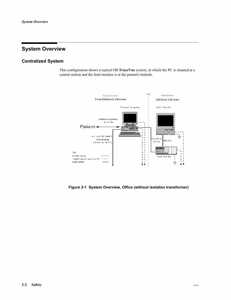
System Overview
2-2 Safety 8081318
System Overview
Centralized System
This configuration shows a typical OB TraceVue system, in which the PC is situated at a central station and the fetal monitor is at the patient's bedside.
Figure 2-1 System Overview, Office (without isolation transformer)
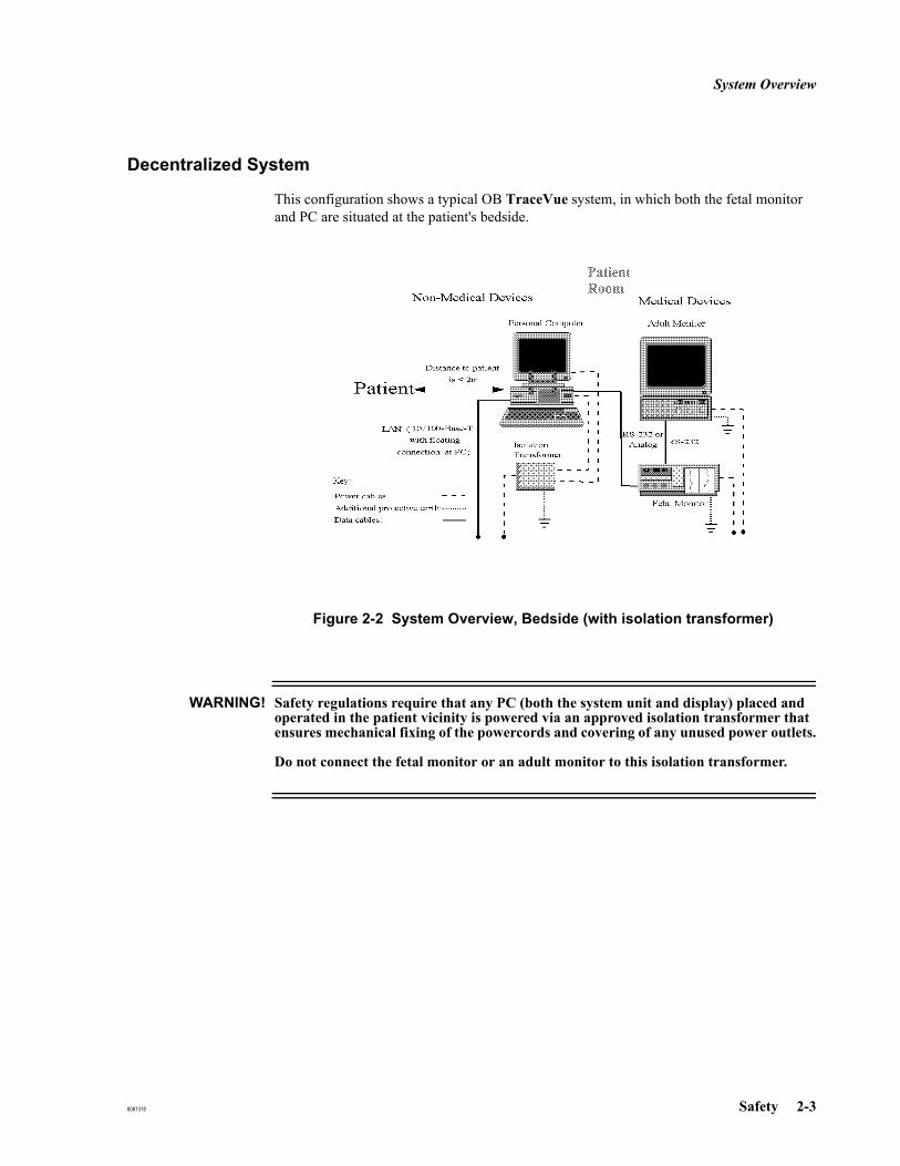
System Overview
8081318 Safety 2-3
Decentralized System
This configuration shows a typical OB TraceVue system, in which both the fetal monitor and PC are situated at the patient's bedside.
Figure 2-2 System Overview, Bedside (with isolation transformer)
WARNING! Safety regulations require that any PC (both the system unit and display) placed and operated in the patient vicinity is powered via an approved isolation transformer that ensures mechanical fixing of the powercords and covering of any unused power outlets.
Do not connect the fetal monitor or an adult monitor to this isolation transformer.
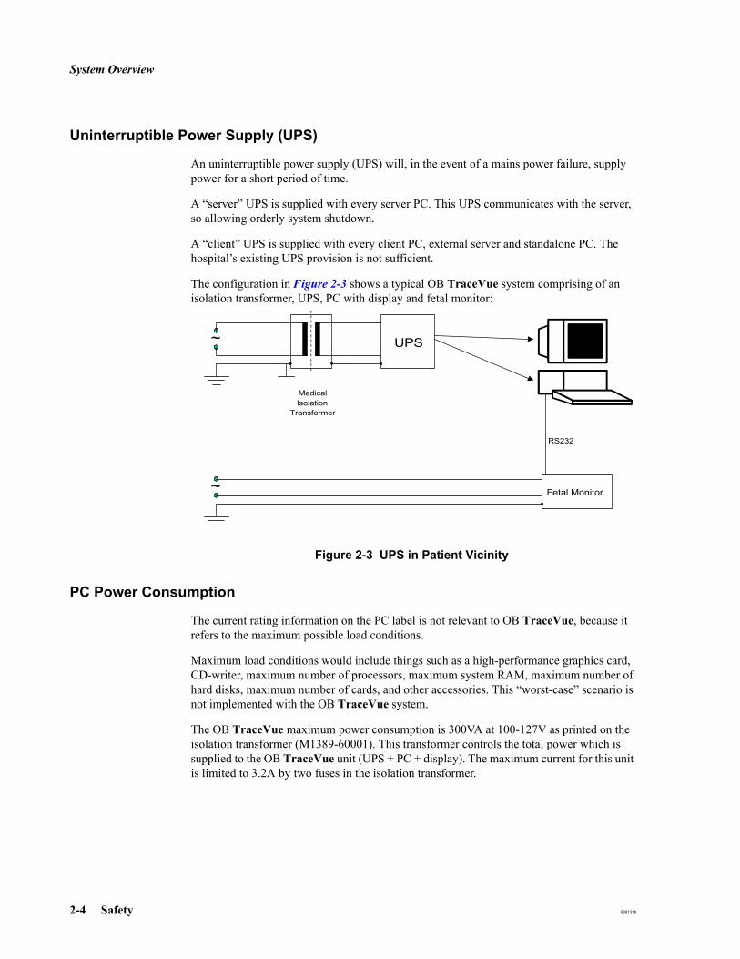
System Overview
2-4 Safety 8081318
Uninterruptible Power Supply (UPS)
An uninterruptible power supply (UPS) will, in the event of a mains power failure, supply power for a short period of time.
A “server” UPS is supplied with every server PC. This UPS communicates with the server, so allowing orderly system shutdown.
A “client” UPS is supplied with every client PC, external server and standalone PC. The hospital’s existing UPS provision is not sufficient.
The configuration in Figure 2-3 shows a typical OB TraceVue system comprising of an isolation transformer, UPS, PC with display and fetal monitor:
Figure 2-3 UPS in Patient Vicinity
PC Power Consumption
The current rating information on the PC label is not relevant to OB TraceVue, because it refers to the maximum possible load conditions.
Maximum load conditions would include things such as a high-performance graphics card, CD-writer, maximum number of processors, maximum system RAM, maximum number of hard disks, maximum number of cards, and other accessories. This “worst-case” scenario is not implemented with the OB TraceVue system.
The OB TraceVue maximum power consumption is 300VA at 100-127V as printed on the isolation transformer (M1389-60001). This transformer controls the total power which is supplied to the OB TraceVue unit (UPS + PC + display). The maximum current for this unit is limited to 3.2A by two fuses in the isolation transformer.
~ UPS
MedicalIsolation
Transformer
Fetal Monitor~
RS232

Safety Test, Verification, and Customer Acceptance Procedures
8081318 Safety 2-5
Safety Test, Verification, and Customer Acceptance ProceduresThis section defines the Test, Verification, and Customer Acceptance procedures applicable to this product.
Use these tables to determine what test and inspection results must be reported for an installation or repair, and to determine the format in which these results must be reported
WARNING! Apply the safety test limits set by the local standards and statutes applicable to the country of installation, such as IEC 601-1, UL2601, CAN/CSA-C22.2 No.601.1.M90
The safety test defined in this chapter is derived from local and international standards but may not be equivalent. It is NOT a substitute for local safety testing.
Caution: Successful completion of the patient safety tests does not ensure correct and accurate operation of the equipment.
When performing safety tests, you must use a standard safety tester. You can use testers complying with IEC 601-1 internationally. You may also use testers complying with any local standards and statutes applicable to the country of the installation. For safety test procedures see the operating instructions of the safety tester used.
When running safety tests on the peripheral components of the system, refer to the documentation included with those products.
Ground leakage current limits apply to the power cables between:Mains supply ↔ isolation transformer (required if PC & Display in patient vicinity) ↔ UPS ↔ PC and Display Monitor
Whenever you connect a patient monitor to the OB TraceVue system perform the Test, Inspection and Safety tests defined for that monitor. Refer to the documentation included with the patient monitor. If significant parts of the monitor have been exchanged, repaired, upgraded or worked on in any way you may be required to perform additional tests.

Test and Inspection Matrix
2-6 Safety 8081318
Test and Inspection Matrix
Test Procedure Name Test or “Inspection” to Perform Expected Test Results What to Record on
Service RecordVisual Inspect all system components for obvious damage.
Are they free of damage?
Is the optical drive environment clean and dust-free?
Expected answers are “yes”.
If so, Visual test is passed.
V:P or V:F
where P=Pass and F=Fail
Power On Power on the PC(s) and/or peripheral(s).
Does the self-test complete successfully?
Are user interface controls operational (for example, keyboard, lightpen, mouse, display, sound)?
Start OB TraceVue:
- Does the train engine icon animate without flashing?
- Is the OB TraceVue icon bar active and accessible?
Expected answers are “yes”.
If so, Power On test is passed.
PO:P or PO:F
where P=Pass and F=Fail
Performance Perform all individual Performance Tests detailed below.
Do all the individual Performance Tests pass?
Expected answer is “yes”.
If so, Performance Test is passed.
P:P or P:F
where P=Pass and F=Fail
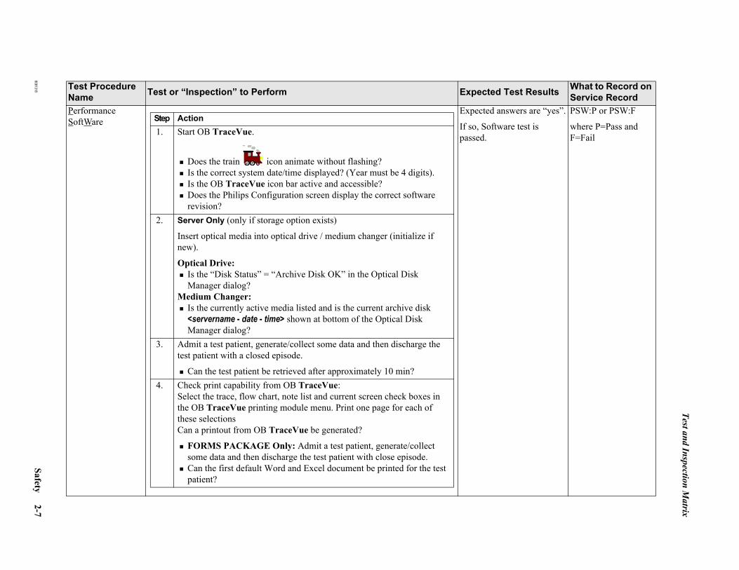
Test and Inspection Matrix
8081318 Safety 2-7
PerformanceSoftWare
Expected answers are “yes”.
If so, Software test is passed.
PSW:P or PSW:F
where P=Pass and F=Fail
Test Procedure Name Test or “Inspection” to Perform Expected Test Results What to Record on
Service Record
Step Action1. Start OB TraceVue.
Does the train icon animate without flashing?Is the correct system date/time displayed? (Year must be 4 digits).Is the OB TraceVue icon bar active and accessible?Does the Philips Configuration screen display the correct software revision?
2. Server Only (only if storage option exists)
Insert optical media into optical drive / medium changer (initialize if new).
Optical Drive:Is the “Disk Status” = “Archive Disk OK” in the Optical Disk Manager dialog?
Medium Changer:Is the currently active media listed and is the current archive disk <servername - date - time> shown at bottom of the Optical Disk Manager dialog?
3. Admit a test patient, generate/collect some data and then discharge the test patient with a closed episode.
Can the test patient be retrieved after approximately 10 min?4. Check print capability from OB TraceVue:
Select the trace, flow chart, note list and current screen check boxes in the OB TraceVue printing module menu. Print one page for each of these selectionsCan a printout from OB TraceVue be generated?
FORMS PACKAGE Only: Admit a test patient, generate/collect some data and then discharge the test patient with close episode.Can the first default Word and Excel document be printed for the test patient?

Test and Inspection Matrix
2-8 Safety 8081318
PerformanceSoftWare(continued)
Test Procedure Name Test or “Inspection” to Perform Expected Test Results What to Record on
Service Record
Step Action5. Check the OB TraceVue to OB TraceVue link.
Admit a test patient, generate/collect some data and then transfer the test patient to the destination OB TraceVue system.
Is the last episode of the test patient available on the destination system?
6. Check the HL7 ADT link.
Admit a test patient on the central hospital information system.
Is the test patient available on the OB TraceVue system?7. Check HL7 ORU (OB TraceVue notes) link.
In the System Manager’s Configuration, set up an HL7 route for Outgo-ing ORU messages.
Configure ORU (notes) messages for that route (for example Event and Remark).
Admit a test patient, go to the Flowchart and enter some test data (for example, Events, Remarks).
Is the test data available at the receiving Application?8. Check WEB/Terminal Server
At a PC connected to the hospital network:
Start Windows Internet Explorer, connect to the WEB/Terminal Server.Enter http://<ip address> (IP address of the WEB/Terminal server exter-nal NIC) or http://<server name> (WEB/Terminal server must be registered in the hostname locating service (eg DNS) of hospital network.
Does the OB TraceVue WEB page open?Does OB TraceVue WEB client start?
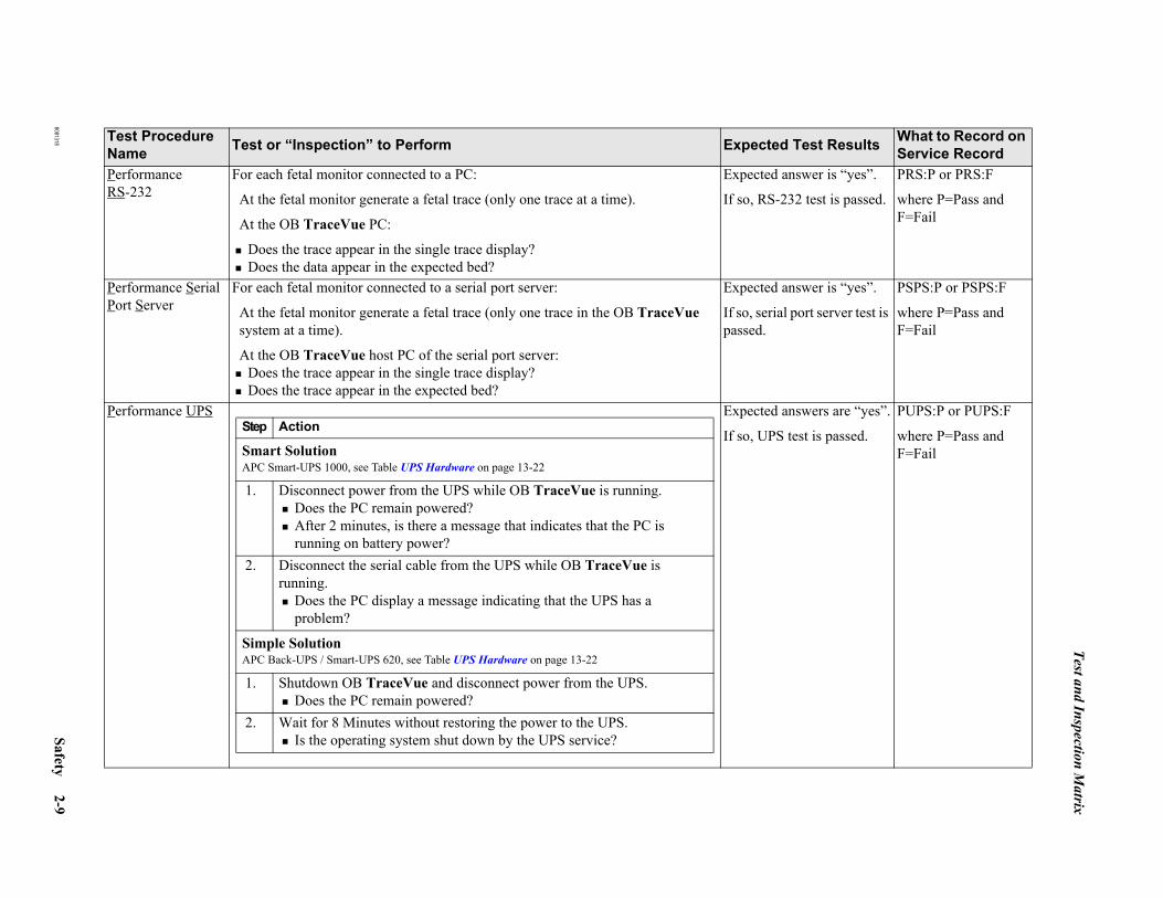
Test and Inspection Matrix
8081318 Safety 2-9
Performance RS-232
For each fetal monitor connected to a PC:
At the fetal monitor generate a fetal trace (only one trace at a time).
At the OB TraceVue PC:
Does the trace appear in the single trace display?Does the data appear in the expected bed?
Expected answer is “yes”.
If so, RS-232 test is passed.
PRS:P or PRS:F
where P=Pass and F=Fail
Performance Serial Port Server
For each fetal monitor connected to a serial port server:
At the fetal monitor generate a fetal trace (only one trace in the OB TraceVue system at a time).
At the OB TraceVue host PC of the serial port server:Does the trace appear in the single trace display?Does the trace appear in the expected bed?
Expected answer is “yes”.
If so, serial port server test is passed.
PSPS:P or PSPS:F
where P=Pass and F=Fail
Performance UPS Expected answers are “yes”.
If so, UPS test is passed.
PUPS:P or PUPS:F
where P=Pass and F=Fail
Test Procedure Name Test or “Inspection” to Perform Expected Test Results What to Record on
Service Record
Step Action
Smart Solution APC Smart-UPS 1000, see Table UPS Hardware on page 13-22
1. Disconnect power from the UPS while OB TraceVue is running.Does the PC remain powered?After 2 minutes, is there a message that indicates that the PC is running on battery power?
2. Disconnect the serial cable from the UPS while OB TraceVue is running.
Does the PC display a message indicating that the UPS has a problem?
Simple SolutionAPC Back-UPS / Smart-UPS 620, see Table UPS Hardware on page 13-22
1. Shutdown OB TraceVue and disconnect power from the UPS.Does the PC remain powered?
2. Wait for 8 Minutes without restoring the power to the UPS.Is the operating system shut down by the UPS service?
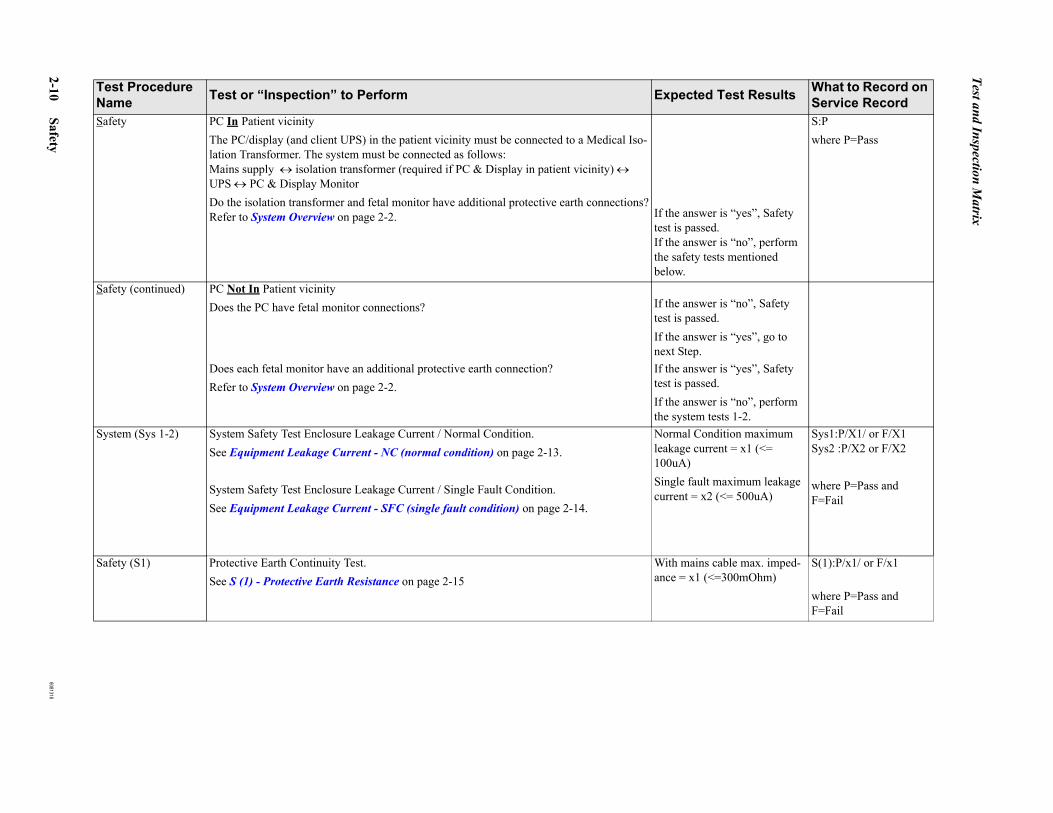
Test and Inspection Matrix
2-10 Safety 8081318
Safety PC In Patient vicinityThe PC/display (and client UPS) in the patient vicinity must be connected to a Medical Iso-lation Transformer. The system must be connected as follows:Mains supply ↔ isolation transformer (required if PC & Display in patient vicinity) ↔ UPS ↔ PC & Display MonitorDo the isolation transformer and fetal monitor have additional protective earth connections?Refer to System Overview on page 2-2. If the answer is “yes”, Safety
test is passed.If the answer is “no”, perform the safety tests mentioned below.
S:P where P=Pass
Safety (continued) PC Not In Patient vicinityDoes the PC have fetal monitor connections? If the answer is “no”, Safety
test is passed.If the answer is “yes”, go to next Step.
Does each fetal monitor have an additional protective earth connection? Refer to System Overview on page 2-2.
If the answer is “yes”, Safety test is passed.If the answer is “no”, perform the system tests 1-2.
System (Sys 1-2) System Safety Test Enclosure Leakage Current / Normal Condition.See Equipment Leakage Current - NC (normal condition) on page 2-13.
System Safety Test Enclosure Leakage Current / Single Fault Condition.See Equipment Leakage Current - SFC (single fault condition) on page 2-14.
Normal Condition maximum leakage current = x1 (<= 100uA)Single fault maximum leakage current = x2 (<= 500uA)
Sys1:P/X1/ or F/X1 Sys2 :P/X2 or F/X2
where P=Pass and F=Fail
Safety (S1) Protective Earth Continuity Test. See S (1) - Protective Earth Resistance on page 2-15
With mains cable max. imped-ance = x1 (<=300mOhm)
S(1):P/x1/ or F/x1
where P=Pass and F=Fail
Test Procedure Name Test or “Inspection” to Perform Expected Test Results What to Record on
Service Record

Test and Inspection Matrix
8081318 Safety 2-11
Safety Test Procedures
Use the test procedures outlined here only for verifying the safe installation or service of the product. The setups used for these tests and the acceptable ranges of values are derived from local and international standards but may not be equivalent. These tests are not a substitute for local safety testing where it is required for an installation or a service event. If using an approved safety tester, perform the tests in accordance with the information provided by the manufacturer of the tester and in accordance with your local regulations, for example IEC/EN 60601-1, UL60601-1 (US), IEC/EN 62353, and IEC/EN 60601-1-1. The safety tester should print results as detailed in this chapter together with other data.
Refer to Annex C of IEC/EN 62353 for requirements for the measurement equipment and for measurement circuits for protective earth resistance and leakage currents.
Supply mains Protective earth
L, N Supply mains terminals PE Protective earth terminal
Mains part Applied part
F-type applied part Measuring device
Resistance measuring deviceConnection to accessible conductive parts
......... Optional connection

Test and Inspection Matrix
2-12 Safety 8081318
Caution: After each service, maintenance or repair event:
Ensure that all fuses accessible from the outside comply with the manufacturer’s specification. Check:the integrity of mechanical parts, internally and externally.
any damage or contamination, internally and externally.
that no loose parts or foreign bodies remain in the device after servicing or repair.
the integrity of all relevant accessories.

Test and Inspection Matrix
8081318 Safety 2-13
Test Procedure Name Test or Inspection to perform
Sys 1 - System
Equipment Leakage Current - NC (normal condition)
Measures leakage current of exposed metal parts of Instrument under Test (IUT) and between parts of the system within the patient vicinity; normal and reversed polarity using S2.
Use CATI-program with all components connected (PC display - transformer system must be tested, the RS-232 and LAN connection must be made).
Apply test to point of patient contact: fetal monitor. The system test detects leakage problems caused by any compo-nent.
Run the test on each fetal monitor. If more than one fetal monitor is connected to the same PC or serial port server,disconnect the power cables of the fetal monitors not being tested.
In the patient vicinity: Run the test on each PC system (includes PC, display, UPS, transformer). The whole system is tested together.
Outside patient vicinity: No component tests.
This safety test is based on IEC 60601-1-1 (clause based on 19.201.1) Report largest value.
(*) Not present in Class 2.(**) Can be multiple different connections to different equipment at same time.
PE
Instrument under test
Applied part
(*)S4N (L)
S1
S2
L (N)
Signal parts
in- and/or
output
MD
Medical electrical system
Signal parts
in- and/or
output
Other
Instrument
(**)
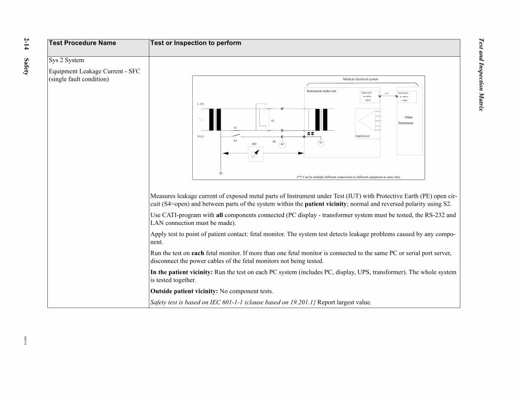
Test and Inspection Matrix
2-14 Safety 8081318
Sys 2 System
Equipment Leakage Current - SFC (single fault condition)
Measures leakage current of exposed metal parts of Instrument under Test (IUT) with Protective Earth (PE) open cir-cuit (S4=open) and between parts of the system within the patient vicinity; normal and reversed polarity using S2.
Use CATI-program with all components connected (PC display - transformer system must be tested, the RS-232 and LAN connection must be made).
Apply test to point of patient contact: fetal monitor. The system test detects leakage problems caused by any compo-nent.
Run the test on each fetal monitor. If more than one fetal monitor is connected to the same PC or serial port server,disconnect the power cables of the fetal monitors not being tested.
In the patient vicinity: Run the test on each PC system (includes PC, display, UPS, transformer). The whole system is tested together.
Outside patient vicinity: No component tests.
Safety test is based on IEC 601-1-1 (clause based on 19.201.1} Report largest value.
Test Procedure Name Test or Inspection to perform
(**) Can be multiple different connections to different equipment at same time.
PE
Instrument under test
Applied part
S4N (L)
S1
S2
L (N)
Signal parts
in- and/or
output
MD
Medical electrical system
Signal parts
in- and/or
output
OtherInstrument
(**)
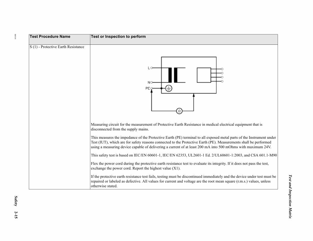
Test and Inspection Matrix
8081318 Safety 2-15
S (1) - Protective Earth Resistance
Measuring circuit for the measurement of Protective Earth Resistance in medical electrical equipment that is disconnected from the supply mains.
This measures the impedance of the Protective Earth (PE) terminal to all exposed metal parts of the Instrument under Test (IUT), which are for safety reasons connected to the Protective Earth (PE). Measurements shall be performed using a measuring device capable of delivering a current of at least 200 mA into 500 mOhms with maximum 24V.
This safety test is based on IEC/EN 60601-1, IEC/EN 62353, UL2601-1 Ed. 2/UL60601-1:2003, and CSA 601.1-M90
Flex the power cord during the protective earth resistance test to evaluate its integrity. If it does not pass the test, exchange the power cord. Report the highest value (X1).
If the protective earth resistance test fails, testing must be discontinued immediately and the device under test must be repaired or labeled as defective. All values for current and voltage are the root mean square (r.m.s.) values, unless otherwise stated.
Test Procedure Name Test or Inspection to perform

Test and Inspection Matrix
2-16 Safety 8081318
When to Perform Test Procedures
Service EventWhen performing.....
Test Procedure(s) RequiredComplete these tests
Installation Visual, Power On, Performance, Safety test procedures.Preventive Maintenance Customer responsibility.Repair - PC (display, internal PC components) Power On, Performance Software, Safety test procedures.
If replacing RS-232 card, also do Performance RS-232 test.
Repair - peripherals (printer, optical drive / medium changer)
Power On, Performance Software.
For printer, only do Performance Software (step 4).For optical drive, only do Steps 1-3 of Performance Soft-ware.
Repair - software reload (Operating system, OB TraceVue)
Power On, Performance.
Repair - RS-232 (cables, converters) Performance RS-232.Repair - Serial Port Server Performance Serial Port Server.Repair - switch/LAN Power On.Repair - UPS Visual, Performance UPS, Safety test procedures.Repair - isolation transformer Visual, Performance UPS, Safety test procedures.Upgrade - add display, memory, 2nd network card
Power On, Performance, Safety test procedures.
Upgrade - add JetDirect card Power On, Performance SoftWare (step 4).Upgrade - add optical (MO) drive Power On, Performance SoftWare (steps 1-3).Upgrade - add optical medium changer Power On, Performance SoftWare (steps 1-3).Upgrade - add RS-232 card Power On, Performance RS-232, Safety test procedures.Upgrade - add serial port server Power On, Performance Serial Port Server.All other Service Events Visual, Power On, Performance, Safety test procedures.
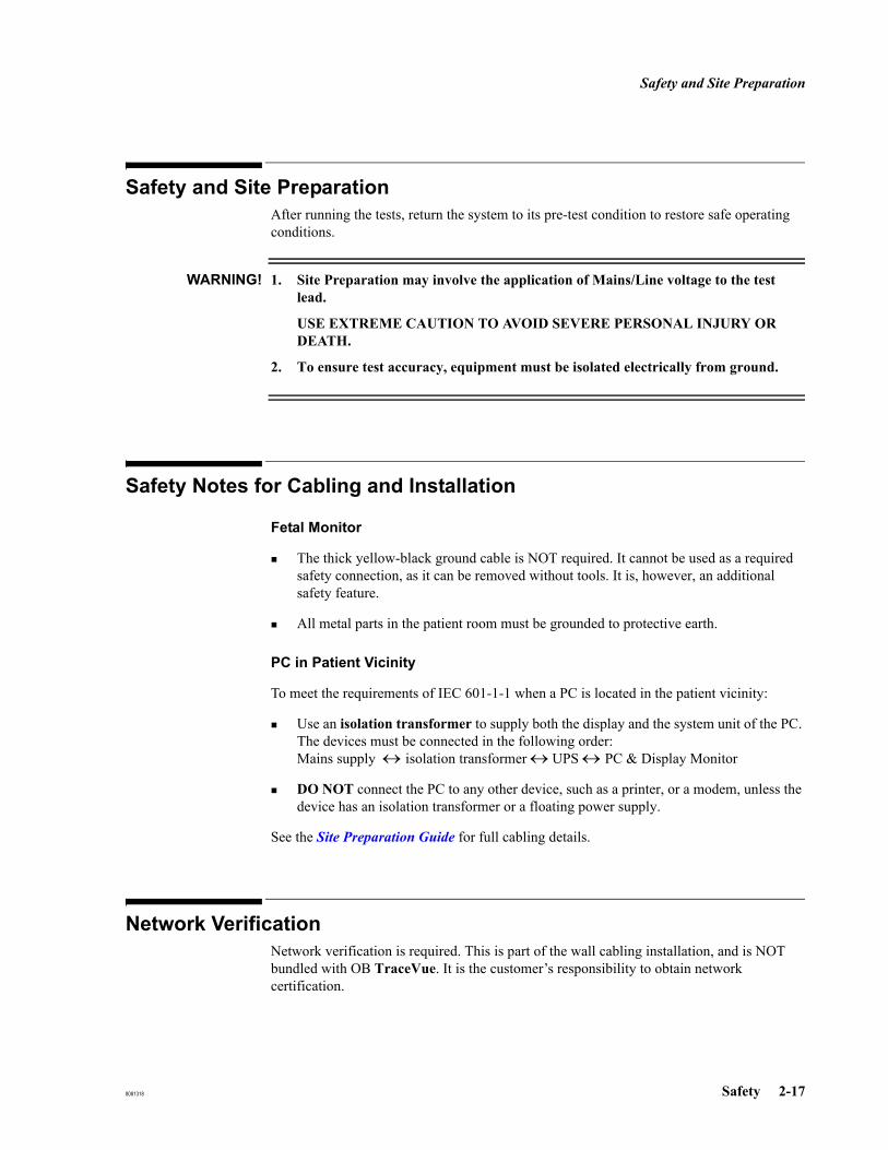
Safety and Site Preparation
8081318 Safety 2-17
Safety and Site Preparation
After running the tests, return the system to its pre-test condition to restore safe operating conditions.
WARNING! 1. Site Preparation may involve the application of Mains/Line voltage to the test lead.
USE EXTREME CAUTION TO AVOID SEVERE PERSONAL INJURY OR DEATH.
2. To ensure test accuracy, equipment must be isolated electrically from ground.
Safety Notes for Cabling and Installation
Fetal Monitor
The thick yellow-black ground cable is NOT required. It cannot be used as a required safety connection, as it can be removed without tools. It is, however, an additional safety feature.
All metal parts in the patient room must be grounded to protective earth.
PC in Patient Vicinity
To meet the requirements of IEC 601-1-1 when a PC is located in the patient vicinity:
Use an isolation transformer to supply both the display and the system unit of the PC. The devices must be connected in the following order:Mains supply ↔ isolation transformer ↔ UPS ↔ PC & Display Monitor
DO NOT connect the PC to any other device, such as a printer, or a modem, unless the device has an isolation transformer or a floating power supply.
See the Site Preparation Guide for full cabling details.
Network VerificationNetwork verification is required. This is part of the wall cabling installation, and is NOT bundled with OB TraceVue. It is the customer’s responsibility to obtain network certification.

Electrostatic Handling Precautions
2-18 Safety 8081318
Electrostatic Handling Precautions
Static electricity can damage electronic components. To prevent damage, observe the following handling precautions:
Use a grounding wrist strap, if available, connected to the metal frame of the computer. To dissipate static electricity, the power cord must be connected between the PC and the wall outlet (by way of the isolation transformer) with the system switched off. If there is no isolation transformer, you require a grounded work place.
Always touch the metal part of the computer frame just before handling a circuit board or disk drive.
Avoid directly touching components or edge connectors on the board. Handle circuit boards and disk drives by their metal brackets or frames.
Emissions and ImmunityThe product is designed and evaluated to comply with the emissions and immunity requirements of international and national EMC standards. See the following tables for detailed information regarding declaration and guidance.
The EMC standards state that manufacturers of patient-coupled equipment must specify immunity levels for their systems. See Table Electromagnetic Immunity - General on page 2-20 and Table Electromagnetic Immunity on page 2-21 for this detailed immunity information. See Table Recommended Separation Distances on page 2-22 for recommended minimum separation distances between portable and mobile communications equipment and the product.
Immunity is defined in the standard as the ability of a system to perform without degradation in the presence of an electromagnetic disturbance. Degradation in system performance is a qualitative assessment which can be subjective.
Caution should, therefore, be taken in comparing immunity levels of different devices. The criteria used for degradation is not specified by the standard and can vary with the manufacturer.
Guidance and Manufacturer’s Declaration
The product is intended for use in the electromagnetic environment specified in the following tables. The customer or the user of the product should assure that it is used in such an environment.

Emissions and Immunity
8081318 Safety 2-19
Table 2-1 Electromagnetic Emissions
Emissions Test Compliance Electromagnetic Environment Guidance
Radio Frequency (RF) emissions
CISPR 11
or
CISPR 22
Group 1
The product uses RF energy only for its internal function. Therefore, its RF emissions are very low and not likely to cause interference in nearby elec-tronic equipment.
RF emissions
CISPR 11
or CISPR 22
Class A
Harmonic emis-sions
IEC 61000-3-2
Class A The product is suitable for use in all establish-ments, other than domestic and those directly con-nected to the public low-voltage power supply network that supplies buildings used for domestic purposes.
Voltage fluctua-tions/flicker emis-sions
IEC 61000-3-3
Complies

Emissions and Immunity
2-20 Safety 8081318
Table 2-2 Electromagnetic Immunity - General
Immunity Test IEC 60601 Test Level
ComplianceLevel Electromagnetic Environment - Guidance
Electrostatic dis-charge (ESD)
IEC 61000-4-2
+ 6 kV contact
+ 8 kV air
+ 6 kV contact
+ 8 kV air
Floors should be wood, concrete, or ceramic tile. If floors are covered with synthetic material, the relative humidity should be at least 30%.
Electrical fast tran-sient/burst
IEC 61000-4-4
+ 2 kV for power supply lines
+1 kV for input/out-put lines
+ 2 kV for power supply lines
+1 kV for input/output lines
Mains power quality should be that of a typical commer-cial or hospital environment.
Surge
IEC 61000-4-5
+ 1 kV differential mode
+ 2 kV common mode
+ 1 kV differential mode
+ 2 kV common mode
Mains power quality should be that of a typical commer-cial or hospital environment.
Voltage dips, short interruptions, and voltage variations on power supply input lines
IEC 61000-4-11
< 5% UT a
(> 95% dip in UT) for 0,5 cycle
40% UT (60% dip in UT) for 5 cycles
70% UT (30% dip in UT) for 25 cycles
< 5% UT (> 95% dip in UT) for 5 sec
< 5% UT a
(> 95% dip in UT) for 0,5 cycle
40% UT (60% dip in UT) for 5 cycles
70% UT (30% dip in UT) for 25 cycles
< 5% UT (> 95% dip in UT) for 5 sec
Mains power quality should be that of a typical commer-cial or hospital environment. If the user of the product requires continued operation during power mains interrup-tions, it is recommended that the product be powered from an uninterruptible power supply or a battery.
Power frequency(50/60 Hz)magnetic field
IEC 61000-4-8
3 A/m 3 A/m Power frequency magnetic fields should be at levels char-acteristic of a typical location in a typical commercial or hospital environment.
a UT is the AC mains voltage prior to application of the test level.

Emissions and Immunity
8081318 Safety 2-21
Table 2-3 Electromagnetic Immunity
Immunity Test IEC 60601Test Level
ComplianceLevel Electromagnetic Environment - Guidance
Portable and mobile RF communications equipment should be used no closer to any part of the product, including cables, than the recommended separation dis-tance calculated from the equation applicable to the fre-quency of the transmitter.
Conducted RF
IEC 61000-4-6
3 Vrms
150 kHz to 80 MHz
3 Vrms
Recommended Separation Distance
Radiated RF
IEC 61000-4-3
3 V/m
80 MHz to 800 MHz
80 MHz to 2.5 GHz
3 V/m
where P is the maximum output power rating of the trans-mitter in watts (W) according to the transmitter’s speci-fied output power and d is the recommended separation distance in meters (m).
Field strengths from fixed RF transmitters, as determined by an electromagnetic site survey,a should be less than the compliance level in each frequency range.b
Interference may occur in the vicinity of equipment marked with the following symbol:
At 80 MHz and 800 MHz, the higher frequency range applies.
These guidelines might not apply in all situations. Electromagnetic propagation is affected by absorption and reflection from structures, objects and people.a Field strengths from fixed transmitters, such as base stations for radio (cellular/cordless) telephones and land mobile radios, amateur radio, AM and FM radio broadcast and TV broadcast cannot be predicted theoretically with accuracy. To assess the electromagnetic environment due to fixed RF transmitters, an electromagnetic site survey should be considered. If the measured field strength in the location in which the product is used exceeds the applicable RF compliance level above, the product should be observed to verify normal operation. If abnormal performance is observed, additional measures are necessary, such as re-orienting or relocating the product.b Over the frequency range 150 kHz to 80 MHz, field strengths should be less than 3 V/m.
Pd 2.1=
Pd 2.1=
Pd 3.2=

Emissions and Immunity
2-22 Safety 8081318
Recommended Separation Distances
The product is intended for use in an electromagnetic environment in which radiated RF disturbances are controlled. The customer or the user of the product can help prevent electromagnetic interference by maintaining a minimum distance between portable and mobile RF communications equipment (transmitters) and the product as recommended below, according to the maximum output power of the communications equipment.
Table 2-4 Recommended Separation Distances
Separation Distance According to Frequency of Transmitter (m)Rated Maximum OutputPower of Transmitter (W)
150 kHZ to 800 MHz 800 MHz to 2.5 GHz
0.01 0.1 m 0.2 m0.1 0.4 m 0.7 m1 1.2 m 2.3 m10 4 m 7 m100 12 m 23 mFor transmitters rated at a maximum output power not listed above, the recommended separation distance d in meters (m) can be determined using the equation applicable to the frequency of the transmitter, where P is the maximum output power rating of the transmitter in watts (W) according to the transmitter’s manufacturer.
At 80 MHz and 800 MHz, the higher frequency range applies.
These guidelines might not apply in all situations. Electromagnetic propagation is affected by absorption and reflection from structures, objects and people.
Pd 2.1= Pd 3.2=

8081318 Security 3-1
3Security
Introduction
OB TraceVue Security
The OB TraceVue configuration and the patient data stored by OB TraceVue are protected by assigning the required user rights such as System Manager and Super User permission and access rights such as Read or Write permissions.
For details refer to the Instructions for Use.
Operating System Security
To protect the OB TraceVue data files against modification, to ensure patient data safety, and to protect the OB TraceVue installation as well as the operating system against corruption only administrators have full access to OB TraceVue computers.
Although standard Windows users have only limited access to the computer they can fully operate OB TraceVue including all system management tasks if they have the corresponding OB TraceVue user rights.
General Security Rules
Do not assign administrator rights to the windows user group users or OBTV users.The standard Windows user log on should be member of the user group users and OBTV users.Windows administrator accounts should only be used for administration purposes.Do not change access rights of directories or shares.
Password Security
The default password for “user” is user4OBTV. It is the customer’s responsibility to change this to a secure password.If access to a PC is not controlled, you are recommended to set a BIOS password.Change administrator passwords on a regular basis.If you are changing the administrator passwords on a high availability system, refer to Changing the Default OB TraceVue User at an HA System.
Windows Security
3-2 Security 8081318
Windows Security
Installation / Configuration of MS Firewall
It is advisable to protect the system with a firewall. To use the MS firewall, execute c:\config\firewall.cmd. You can do this on all PCs except the HA server pair.
Caution: Do not use more than one firewall on a system.
Windows User Groups
OBTV Internal Created by the OB TraceVue setup.Do not add users to this group; do not change any setting of this group.
OBTV Users Created by the OB TraceVue setup.Users who are not members of Administrators must be member of this group in order to start OB TraceVue.Do not change any setting of this group.
Administrators Predefined by Windows.Members are able to grant themselves access to the computer.
Users Predefined by Windows.Members have limited access to the computer.
Windows Users
OBTV InternalOBTV Connect
For internal use by OB TraceVue only.It is not possible to log onto Windows using this account.Do not change any setting of these users.
OBTVAdministrator
For administration purposes, member of Administrators.Cannot grant full access to the computer.It is recommended to change the password after OB TraceVue installation.
Administrator Predefined by Windows, member of Administrators.Can grant full access to the computer.It is recommended to change the password after OB TraceVue installation.
User Default user account for running OB TraceVue, member of users and OBTV users.Limited access to the computer.It is not possible to run applications that require administrator rights using this user account.

Windows Security
8081318 Security 3-3
Table 3-1 Windows Users and Groups
UserUser Group
OBTV Internal Administrators Users OBTV Users
OBTV InternalOBTV ConnectOBTV AdministratorUserAdministrator

Windows Security
3-4 Security 8081318
Access Rights
Data on the hard disk of OB TraceVue PCs is protected by Windows access rights:
Members of the groups Administrators and OBTV Internal have full access to the OB TraceVue directories, shares, and registry settings.All other users have limited access:
DirectoriesTable 3-2 Directory Access Rights (of users not member of Administrators)
Directory Access Rights
C:\TV2 Read & ExecuteC:\TV2\cfg_exp Read & ExecuteC:\TV2\db No AccessC:\TV2\dbbackup No AccessC:\TV2\extdb1
1. External Server PC only
No AccessC:\TV2\hl7 Read & ExecuteC:\TV2\logdata Full ControlC:\TV2\patdata Read & ExecuteC:\TV2\prog Read & ExecuteC:\TV2\setup Read & ExecuteC:\TV2\sounds Read & ExecuteC:\TV2\sqlany Read & ExecuteC:\TV2\tools Read & ExecuteD:\TV22
2. Archive systems only (no RAID)
No AccessD:\TV2\db No AccessD:\TV2\dbbackup No Access
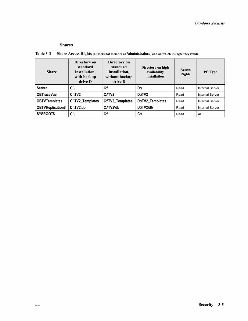
Windows Security
8081318 Security 3-5
Shares
Table 3-3 Share Access Rights (of users not member of Administrators) and on which PC type they reside
Share
Directory on standard
installation, with backup
drive D
Directory on standard
installation, without backup
drive D
Directory on high availability installation
Access Rights PC Type
Server C:\ C:\ D:\ Read Internal Server
OBTraceVue C:\TV2 C:\TV2 D:\TV2 Read Internal Server
OBTVTemplates C:\TV2_Templates C:\TV2_Templates D:\TV2_Templates Read Internal Server
OBTVReplication$ D:\TV2\db C:\TV2\db D:\TV2\db Read Internal Server
SYSROOT$ C:\ C:\ C:\ Read All
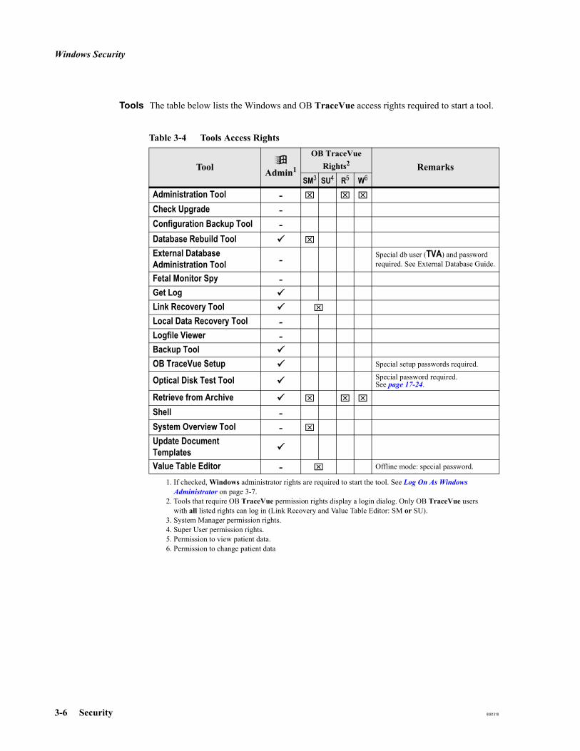
Windows Security
3-6 Security 8081318
Tools The table below lists the Windows and OB TraceVue access rights required to start a tool.
Table 3-4 Tools Access Rights
Tool Admin1
1. If checked, Windows administrator rights are required to start the tool. See Log On As Windows Administrator on page 3-7.
OB TraceVue Rights2
2. Tools that require OB TraceVue permission rights display a login dialog. Only OB TraceVue users with all listed rights can log in (Link Recovery and Value Table Editor: SM or SU).
RemarksSM3
3. System Manager permission rights.
SU4
4. Super User permission rights.
R5
5. Permission to view patient data.
W6
6. Permission to change patient data
Administration Tool - ⌧ ⌧ ⌧
Check Upgrade -Configuration Backup Tool -Database Rebuild Tool ⌧
External Database Administration Tool - Special db user (TVA) and password
required. See External Database Guide.
Fetal Monitor Spy -Get LogLink Recovery Tool ⌧
Local Data Recovery Tool -Logfile Viewer -Backup ToolOB TraceVue Setup Special setup passwords required.
Optical Disk Test Tool Special password required.See page 17-24.
Retrieve from Archive ⌧ ⌧ ⌧
Shell -System Overview Tool - ⌧
Update Document TemplatesValue Table Editor - ⌧ Offline mode: special password.
Windows Security
8081318 Security 3-7
Interrupting Auto Login
If Windows Auto Login (see Auto Login on page 18-9) is configured you need to interrupt that in order to login as a different Windows user.
Hold down the Shift key while Windows is booting.
Log On As Windows Administrator
If administrator rights are required (for example, to start a tool or to install drivers):
1. Shut down OB TraceVue.2. Log off Windows.3. Log on Windows as a user who is member of the Windows Adminstrators user group
(for example, OBTV Administrator or Administrator).4. Start the tool.5. When finished, log off, log on as user.6. Start OB TraceVue.
Modifying Access Rights
For some tasks (for example installation of Word/Excel service releases) it is not sufficient to log on as an administrator. Instead, the user user requires administrator rights:
After having finished driver installation remove the user user from the Administrators group to restore security.
Adding User toAdministrators
Group
1. Log on as Windows administrator.2. Start Computer Management → Local Users and Groups, select Users.3. Double-click user.4. Click the Member Of tab, click Add ...5. Select Administrators, click Add.6. Click OK.
Removing Userfrom
AdministratorsGroup
1. Start Computer Management → Local Users and Groups, select Users.2. Double-click user.3. Click the Member Of tab4. Select Administrators, click Remove.5. Click OK.

Windows Security
3-8 Security 8081318
8081318 System Description 4-1
4System Description
OverviewOB TraceVue is a PC-based network system for obstetrical surveillance, alarming, and patient data management. For system specifications (such as number of supported PCs or fetal monitors, see Hardware on page 20-2.
Key options include patient data storage to optical disk; an external server used, for example, to facilitate forms based patient records and statistical reporting; an optional HL7 link for Admission Discharge Transfer (ADT) messages and ORU (OB TraceVue notes) messages; and an optional WEB access.
Operating system: Microsoft Windows Server 2003 for a standalone PC, internal server, and (optional) external database and WEB/TS server PCs; Microsoft Windows XP Professional at client PCs.
Relational Database: Sybase Adaptive Server Anywhere 9
Optional forms based patient documentation and statistical reporting using Microsoft Word and Excel templates.
Network: Microsoft Windows 2003, client-server structure, with star topology, Ethertwist 100baseT cabling.
The cable between a fetal monitor and PC uses DB-9 connectors. Where necessary for the fetal monitor, an RS-232 protocol converter is used.
Centralized Implementation
4-2 System Description 8081318
Centralized Implementation
A centralized implementation includes:
An internal server.
Client PCs at Central Station, used for data acquisition.
An optional serial port server used to connect up to 16 fetal monitors.
An optional external server, never used for data acquisition.
Fetal monitors in patient rooms, connected to wallplates.
A switch, for PC to PC and other network connections, perhaps located at the Central Station.
Wall cabling: Serial (RS-232) connection between client PCs and fetal monitors:
Cable-type: Ethertwist UTP.
Connectors: 9 pin DSUB.
Installation: 865072, option K41 Serial wall-cable kit (kit for six Fetal Monitors).
Decentralized Implementation
A decentralized implementation includes:
An internal server in a secure location.
Client PCs at Central Station, not used for data acquisition.
An optional External server, never used for data acquisition.
An optional WEB/Terminal server, never used for data acquisition.
Client PCs in patient rooms next to fetal monitors allowing bedside data entry(Isolation transformer required in patient vicinity).
Fetal monitors in patient rooms connected directly to client PC.
One or more switches, for PC to PC and other network connections, typically located in cable room(s).
Wall cabling: LAN-connection between server, clients and switch.
Cable-type: Ethertwist UTP.Connectors: RJ45.Installation: 865072, opt K42 LAN wall-cable kit (kit for 6 PCs).

Shipment Status
8081318 System Description 4-3
Shipment Status
If the PC is an internal server or external server or standalone, the Microsoft Windows Server 2003 is pre-installed. If the PC is a client, Microsoft Windows XP Professional is pre-installed.
If the optional external server is ordered with the optional forms based patient record licence, Microsoft Word and Excel are pre-installed.
All the internal hardware components ordered for a PC are fitted by the factory. For example: a serial interface card, or the SCSI host adapter and additional hard disk required for an internal server with archiving.
Any software, such as additional drivers, required for the internal components fitted to a PC is pre-installed. Any settings required (such as IRQ allocation, address or DMA settings) are made by the factory.
An external component, such an optical drive, may require some setup.
For PCs supplied for new systems, the appropriate OB TraceVue software is pre-installed.
For upgrade PCs, the appropriate OB TraceVue application software must be installed on-site.
The printer driver is not installed. You may need to amend the PC BIOS to enable its parallel port, and install a printer driver. You may need to connect PCs to a printer that is shared with other PCs in the LAN, or to a printer that has been connected to the LAN using a JetDirect card.
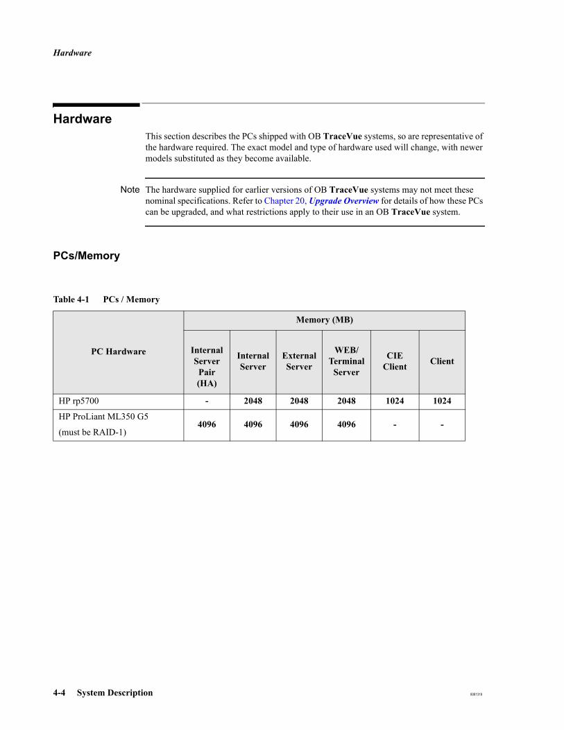
Hardware
4-4 System Description 8081318
Hardware
This section describes the PCs shipped with OB TraceVue systems, so are representative of the hardware required. The exact model and type of hardware used will change, with newer models substituted as they become available.
Note The hardware supplied for earlier versions of OB TraceVue systems may not meet these nominal specifications. Refer to Chapter 20, Upgrade Overview for details of how these PCs can be upgraded, and what restrictions apply to their use in an OB TraceVue system.
PCs/Memory
Table 4-1 PCs / Memory
PC Hardware
Memory (MB)
Internal Server Pair (HA)
Internal Server
External Server
WEB/Terminal
Server
CIE Client Client
HP rp5700 - 2048 2048 2048 1024 1024
HP ProLiant ML350 G5
(must be RAID-1)4096 4096 4096 4096 - -
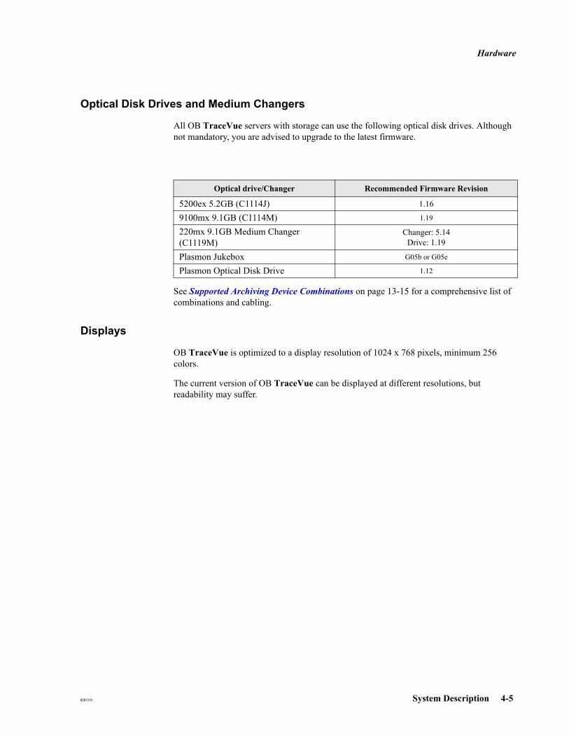
Hardware
8081318 System Description 4-5
Optical Disk Drives and Medium Changers
All OB TraceVue servers with storage can use the following optical disk drives. Although not mandatory, you are advised to upgrade to the latest firmware.
See Supported Archiving Device Combinations on page 13-15 for a comprehensive list of combinations and cabling.
Displays
OB TraceVue is optimized to a display resolution of 1024 x 768 pixels, minimum 256 colors.
The current version of OB TraceVue can be displayed at different resolutions, but readability may suffer.
Optical drive/Changer Recommended Firmware Revision
5200ex 5.2GB (C1114J) 1.16
9100mx 9.1GB (C1114M) 1.19
220mx 9.1GB Medium Changer (C1119M)
Changer: 5.14Drive: 1.19
Plasmon Jukebox G05b or G05e
Plasmon Optical Disk Drive 1.12
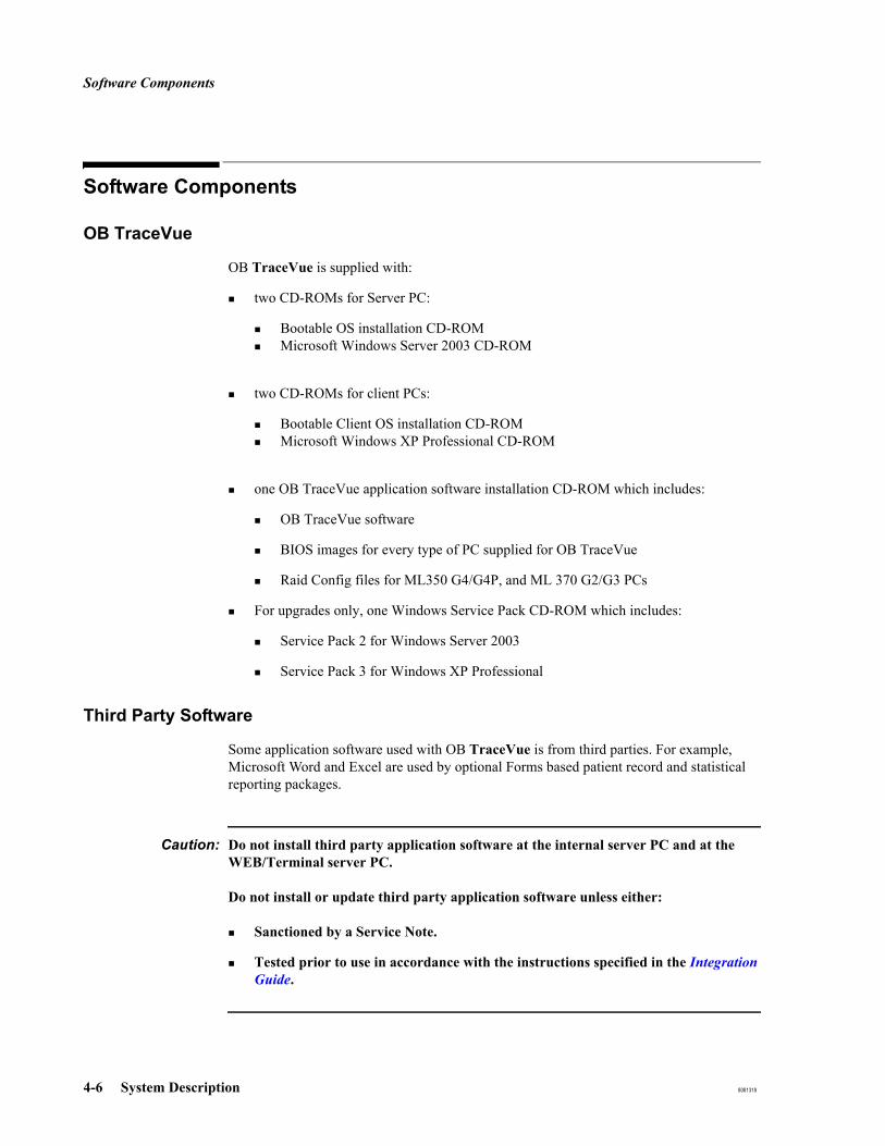
Software Components
4-6 System Description 8081318
Software Components
OB TraceVue
OB TraceVue is supplied with:
two CD-ROMs for Server PC:
Bootable OS installation CD-ROMMicrosoft Windows Server 2003 CD-ROM
two CD-ROMs for client PCs:
Bootable Client OS installation CD-ROMMicrosoft Windows XP Professional CD-ROM
one OB TraceVue application software installation CD-ROM which includes:
OB TraceVue software
BIOS images for every type of PC supplied for OB TraceVue
Raid Config files for ML350 G4/G4P, and ML 370 G2/G3 PCs
For upgrades only, one Windows Service Pack CD-ROM which includes:
Service Pack 2 for Windows Server 2003
Service Pack 3 for Windows XP Professional
Third Party Software
Some application software used with OB TraceVue is from third parties. For example, Microsoft Word and Excel are used by optional Forms based patient record and statistical reporting packages.
Caution: Do not install third party application software at the internal server PC and at the WEB/Terminal server PC.
Do not install or update third party application software unless either:
Sanctioned by a Service Note.
Tested prior to use in accordance with the instructions specified in the Integration Guide.

Wall Cabling and Faceplates
8081318 System Description 4-7
Wall Cabling and Faceplates
Refer to the Site Preparation Guide for this information.

System Limitations
4-8 System Description 8081318
System LimitationsOB TraceVue has certain implementation restrictions:1
Power
An isolation transformer is required for any PC operated in the patient vicinity, even when a UPS is used. The isolation transformer must be connected in the following order:Mains supply ↔ isolation transformer ↔ UPS ↔ PC & Display Monitor
Switches and serial port servers must have a stable power supply. If possible connect to UPS.
PCs and Fetal Monitors
Each PC supports a maximum of four local RS-232 serial ports2.
A small surveillance system (internal server, no forms based patient record and no more than 20 clients) may have up to 16 fetal monitors connected to the internal server, one COM port being used by the server UPS. If all COM ports are used to connect fetal monitors the server UPS must be used off-line. In the event of a power outage the server must be shut down manually.
If more than 20 clients are connected to the server, no fetal monitors may be connected to the internal server.
A maximum of 16 fetal monitors (FMs) may be connected directly to one PC.
A maximum of 150 clients may be online at any one time with the HA internal server pair. See also Maximum Number of Clients Per System on page 20-3.
We do not support using the Compaq ProLiant ML 370, or ML 350 PC as a workstation; it is intended as a server PC and must be installed in a secure area.
1. These restrictions apply to a new OB TraceVue system. Other restrictions may apply to hardware supplied for earlier an OB TraceVue version that has been upgraded to the current version.
2. An optional additional RS-232 PCI serial interface card is used to provide COM3 and COM4
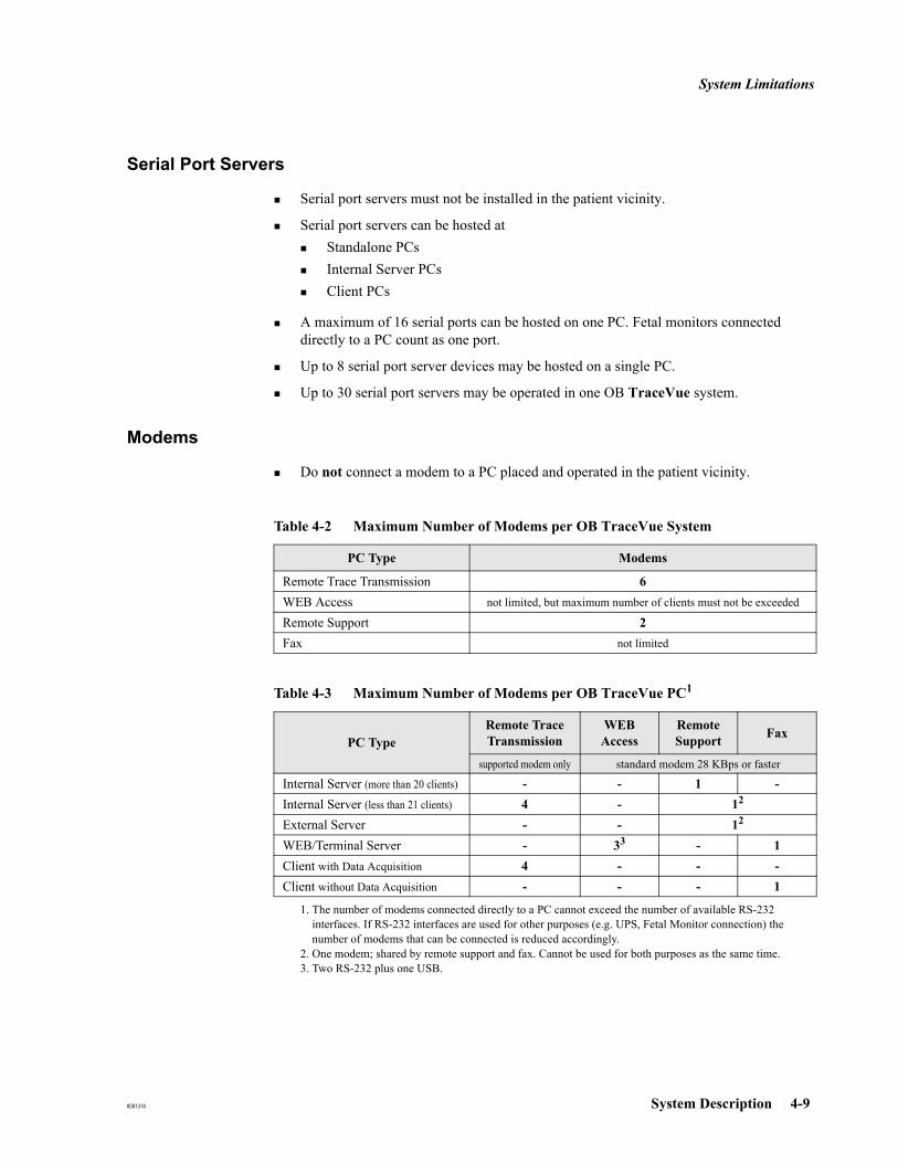
System Limitations
8081318 System Description 4-9
Serial Port Servers
Serial port servers must not be installed in the patient vicinity.
Serial port servers can be hosted at Standalone PCsInternal Server PCsClient PCs
A maximum of 16 serial ports can be hosted on one PC. Fetal monitors connected directly to a PC count as one port.
Up to 8 serial port server devices may be hosted on a single PC.
Up to 30 serial port servers may be operated in one OB TraceVue system.
Modems
Do not connect a modem to a PC placed and operated in the patient vicinity.
Table 4-2 Maximum Number of Modems per OB TraceVue System
PC Type Modems
Remote Trace Transmission 6WEB Access not limited, but maximum number of clients must not be exceeded
Remote Support 2Fax not limited
Table 4-3 Maximum Number of Modems per OB TraceVue PC1
1. The number of modems connected directly to a PC cannot exceed the number of available RS-232 interfaces. If RS-232 interfaces are used for other purposes (e.g. UPS, Fetal Monitor connection) the number of modems that can be connected is reduced accordingly.
PC TypeRemote Trace Transmission
WEB Access
Remote Support Fax
supported modem only standard modem 28 KBps or faster
Internal Server (more than 20 clients) - - 1 -Internal Server (less than 21 clients) 4 - 12
2. One modem; shared by remote support and fax. Cannot be used for both purposes as the same time.
External Server - - 12
WEB/Terminal Server - 33
3. Two RS-232 plus one USB.
- 1Client with Data Acquisition 4 - - -Client without Data Acquisition - - - 1

System Limitations
4-10 System Description 8081318
Interfacing
Additional network interface cards are allowed only on WEB/Terminal Server PCs, and client PCs without data acquisition.
The optional HL7 interface can be installed on a client PC not used for data acquisition (CIE client).
If the HL7 interface is used in ADT-only mode, the HL7 interface can be installed together with the CareVue Integration Engine (CIE) on one PC.
If the HL7 interface is used for ADT and ORU export, the CIE must be installed on a separate client PC.
Database export to the hospital network (optional) requires the optional external database server.
Network
The HA internal server pair allows a maximum 150 client PCs to be online at any one time. See also Maximum Number of Clients Per System on page 20-3.
A client PC used to facilitate the optional HL7 interface counts as a client connection.
The optional External server and each WEB/Terminal client session count as a client connection to the internal server.

Documentation
8081318 System Description 4-11
DocumentationThis documentation and software described here originates from Philips and third party suppliers.
This section describes the documentation that is supplied with the OB TraceVue hardware, depending on the options ordered. Documentation is available on the documentation CD-ROM for other manuals not mentioned in this list. The HP PC’s Service Manual, and Windows manuals are not supplied.
OB TraceVue:
Instructions for UseSystem Administration and Configuration GuideIntegration GuideSite Preparation GuideInstallation and Service Manual
Other Documentation:
Microsoft Windows Server documentation.(On CD-ROM - Paper documentation is not supplied)PC documentation CD ROMAny documentation supplied with PCI network cardAny documentation supplied with RS-232 serial interface cardSCSI host adapter documentationHP Optical Disk Drive documentationHP Optical Jukebox Model 125ex/220mx Service ManualDisplay User's GuideHP Switch Installation and Reference GuideAPC Back-UPS User’s Manual (with optional client UPS)HP documentation supplied with printer.Moxa NPort Server User’s ManualPlasmon Gx Libraries Gx24 - Gx80 - UDO/MO Driver User and Service ManualCareVue Integration Engine (CIE) Installation and Configuration Guide

Documentation
4-12 System Description 8081318
Introduction
8081318 New System Setup 5-1
5New System Setup
IntroductionThis chapter tells you how to get a new system up and running. Most hardware and software is pre-installed at the factory but you have to connect and configure the system.
You should also check the Technical Marketing Softserver for the latest OB TraceVue service pack and ensure that it is installed.
PC Types
There are different types of OB TraceVue PCs:
Internal Server PC (includes server without client PCs; formerly: Standalone)External Server PCWEB/Terminal Server PCHigh-end Data Acquisition ServerClient PCs used for data acquisition from fetal monitors (Client Data Acq.)Client PCs not used for data acquisition (Other Client)
This chapter consists of a sequence of tasks you must do to install all types of PCs. Each tasks starts with a small table indicating for which PC type(s) the task is relevant. To install an OB TraceVue PC, start with task number 1 and go through the tasks that are marked for your PC type.
A description of how to start WEB clients and install real-time WEB clients can be found at the end of this chapter.
Order in which to Perform Tasks
The order in which you perform the tasks is important. When installing a system (server and at least one client), please observe the following workflow:
1. Install the internal server.2. Install each client.
X Internal ServerExternal ServerWEB/Terminal ServerClient Data Acq.Other Client
X High-end Data Acquisition Server

Installation Checklists
5-2 New System Setup 8081318
Installation ChecklistsThe following pages are installation checklists, one for each PC type. To use the installation checklists:
For each PC in your installation:
1. Determine the type of PC (server, standalone, external server, WEB/Terminal server, client with data acquisition, or other client). Make a copy of the appropriate installation checklist.
2. Install the PC by performing the tasks in the checklist. If a check box is enclosed in parentheses, the task is optional or conditional.For each task, the task number refers to the tasks as described in this chapter. The page number(s) refer(s) to the page(s) where information on how to perform the task can be found. Page numbers in bold type refer to the pages with the greatest level of detail.
3. After completing a task, check the check box in the checklist. When you have finished installing all PCs, staple all the installation checklists together and store them.
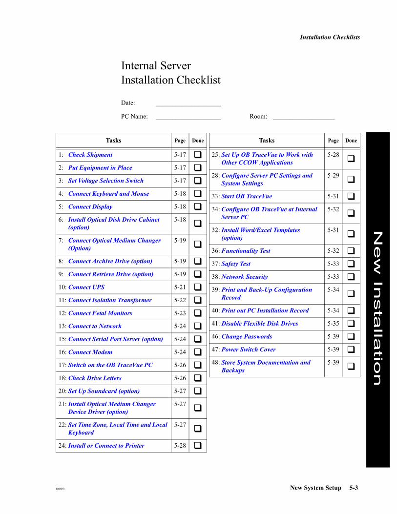
Installation Checklists
8081318 New System Setup 5-3
Internal ServerInstallation Checklist
Date: ____________________
PC Name: ____________________ Room: ___________________
Tasks Page Done
1: Check Shipment 5-17
2: Put Equipment in Place 5-17
3: Set Voltage Selection Switch 5-17
4: Connect Keyboard and Mouse 5-18
5: Connect Display 5-18
6: Install Optical Disk Drive Cabinet (option)
5-18
7: Connect Optical Medium Changer (Option)
5-19
8: Connect Archive Drive (option) 5-19
9: Connect Retrieve Drive (option) 5-19
10: Connect UPS 5-21
11: Connect Isolation Transformer 5-22
12: Connect Fetal Monitors 5-23
13: Connect to Network 5-24
15: Connect Serial Port Server (option) 5-24
16: Connect Modem 5-24
17: Switch on the OB TraceVue PC 5-26
18: Check Drive Letters 5-26
20: Set Up Soundcard (option) 5-27
21: Install Optical Medium Changer Device Driver (option)
5-27
22: Set Time Zone, Local Time and Local Keyboard
5-27
24: Install or Connect to Printer 5-28
25: Set Up OB TraceVue to Work with Other CCOW Applications
5-28
28: Configure Server PC Settings and System Settings
5-29
33: Start OB TraceVue 5-31
34: Configure OB TraceVue at Internal Server PC
5-32
32: Install Word/Excel Templates (option)
5-31
36: Functionality Test 5-32
37: Safety Test 5-33
38: Network Security 5-33
39: Print and Back-Up Configuration Record
5-34
40: Print out PC Installation Record 5-34
41: Disable Flexible Disk Drives 5-35
46: Change Passwords 5-39
47: Power Switch Cover 5-39
48: Store System Documentation and Backups
5-39
Tasks Page Done
New
Insta
llatio
n

Installation Checklists
5-4 New System Setup 8081318
This page intentionally left blank.
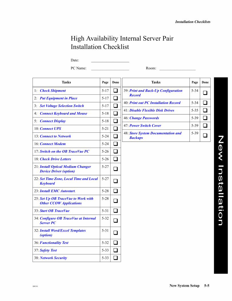
Installation Checklists
8081318 New System Setup 5-5
High Availability Internal Server PairInstallation Checklist
Date: ____________________
PC Name: ____________________ Room: ___________________
Tasks Page Done
1: Check Shipment 5-17
2: Put Equipment in Place 5-17
3: Set Voltage Selection Switch 5-17
4: Connect Keyboard and Mouse 5-18
5: Connect Display 5-18
10: Connect UPS 5-21
13: Connect to Network 5-24
16: Connect Modem 5-24
17: Switch on the OB TraceVue PC 5-26
18: Check Drive Letters 5-26
21: Install Optical Medium Changer Device Driver (option)
5-27
22: Set Time Zone, Local Time and Local Keyboard
5-27
23: Install EMC Autostart. 5-28
25: Set Up OB TraceVue to Work with Other CCOW Applications
5-28
33: Start OB TraceVue 5-31
34: Configure OB TraceVue at Internal Server PC
5-32
32: Install Word/Excel Templates (option)
5-31
36: Functionality Test 5-32
37: Safety Test 5-33
38: Network Security 5-33
39: Print and Back-Up Configuration Record
5-34
40: Print out PC Installation Record 5-34
41: Disable Flexible Disk Drives 5-35
46: Change Passwords 5-39
47: Power Switch Cover 5-39
48: Store System Documentation and Backups
5-39
Tasks Page Done
New
Insta
llatio
n

Installation Checklists
5-6 New System Setup 8081318
This page intentionally left blank.

Installation Checklists
8081318 New System Setup 5-7
External Database ServerInstallation Checklist
Date: ____________________
PC Name: ____________________ Room: _____________________
Tasks Page Done
1: Check Shipment 5-17
2: Put Equipment in Place 5-17
3: Set Voltage Selection Switch 5-17
4: Connect Keyboard and Mouse 5-18
5: Connect Display 5-18
6: Install Optical Disk Drive Cabinet (option). Only for HA server pair.
5-18
7: Connect Optical Medium Changer (Option). Only for HA server pair.
5-19
8: Connect Archive Drive (option). Only for HA server pair.
5-19
9: Connect Retrieve Drive (option). Only for HA server pair.
5-19
10: Connect UPS 5-21
13: Connect to Network 5-24
16: Connect Modem 5-24
17: Switch on the OB TraceVue PC 5-26
20: Set Up Soundcard (option) 5-27
22: Set Time Zone, Local Time and Local Keyboard
5-27
24: Install or Connect to Printer 5-28
25: Set Up OB TraceVue to Work with Other CCOW Applications
5-28
26: Software Engineering for 3rd Party Data Access
5-28
27: Software Engineering for HL7 Inter-face (option)
5-29
29: Configure External Server PC Set-tings
5-30
33: Start OB TraceVue 5-31
35: Configure OB TraceVue at Client PCs
5-32
36: Functionality Test 5-32
38: Network Security 5-33
40: Print out PC Installation Record 5-34
41: Disable Flexible Disk Drives 5-35
42: Prepare Backup of External Data-base
5-35
46: Change Passwords 5-39
47: Power Switch Cover 5-39
48: Store System Documentation and Backups
5-39
Tasks Page Done
New
Insta
llatio
n

Installation Checklists
5-8 New System Setup 8081318
This page intentionally left blank.

Installation Checklists
8081318 New System Setup 5-9
WEB/Terminal ServerInstallation Checklist
Date: ____________________
PC Name: ____________________ Room: _____________________
Tasks Page Done
1: Check Shipment 5-17
2: Put Equipment in Place 5-17
3: Set Voltage Selection Switch 5-17
4: Connect Keyboard and Mouse 5-18
5: Connect Display 5-18
10: Connect UPS 5-21
13: Connect to Network 5-24
14: Connect Second Network Card (option for Web/Terminal Server or client without data acquisition only)
5-24
16: Connect Modem 5-24
17: Switch on the OB TraceVue PC 5-26
22: Set Time Zone, Local Time and Local Keyboard
5-27
24: Install or Connect to Printer 5-28
30: Configure WEB/Terminal Server PC Settings (optional)
5-30
36: Functionality Test 5-32
38: Network Security 5-33
40: Print out PC Installation Record 5-34
41: Disable Flexible Disk Drives 5-35
43: License Balancing (optional) 5-36
44: Activate License Server 5-37
45: Install Terminal Server Client Access Licenses
5-38
46: Change Passwords 5-39
47: Power Switch Cover 5-39
48: Store System Documentation and Backups
5-39
Tasks Page Done
New
Insta
llatio
n

Installation Checklists
5-10 New System Setup 8081318
This page intentionally left blank.

Installation Checklists
8081318 New System Setup 5-11
Client with Data AcquisitionInstallation Checklist
Date: ____________________
PC Name: ____________________ Room: ____________________
Tasks Page Done
1: Check Shipment 5-17
2: Put Equipment in Place 5-17
3: Set Voltage Selection Switch 5-17
4: Connect Keyboard and Mouse 5-18
5: Connect Display 5-18
10: Connect UPS 5-21
11: Connect Isolation Transformer 5-22
12: Connect Fetal Monitors 5-23
13: Connect to Network 5-24
15: Connect Serial Port Server (option) 5-24
16: Connect Modem 5-24
17: Switch on the OB TraceVue PC 5-26
19: Install Touchscreen Driver (option) 5-26
20: Set Up Soundcard (option) 5-27
22: Set Time Zone, Local Time and Local Keyboard
5-27
24: Install or Connect to Printer 5-28
25: Set Up OB TraceVue to Work with Other CCOW Applications
5-28
31: Configure Client PC Settings 5-30
33: Start OB TraceVue 5-31
35: Configure OB TraceVue at Client PCs
5-32
36: Functionality Test 5-32
37: Safety Test 5-33
38: Network Security 5-33
40: Print out PC Installation Record 5-34
41: Disable Flexible Disk Drives 5-35
46: Change Passwords 5-39
47: Power Switch Cover 5-39
48: Store System Documentation and Backups
5-39
Tasks Page Done
New
Insta
llatio
n

Installation Checklists
5-12 New System Setup 8081318

Installation Checklists
8081318 New System Setup 5-13
High-end Data Acquisition ServerInstallation Checklist
Date: ____________________
PC Name: ____________________ Room: ____________________
Tasks Page Done
1: Check Shipment 5-17
2: Put Equipment in Place 5-17
3: Set Voltage Selection Switch 5-17
4: Connect Keyboard and Mouse 5-18
5: Connect Display 5-18
10: Connect UPS 5-21
12: Connect Fetal Monitors 5-23
13: Connect to Network 5-24
15: Connect Serial Port Server (option) 5-24
17: Switch on the OB TraceVue PC 5-26
19: Install Touchscreen Driver (option) 5-26
22: Set Time Zone, Local Time and Local Keyboard
5-27
31: Configure Client PC Settings 5-30
33: Start OB TraceVue 5-31
35: Configure OB TraceVue at Client PCs
5-32
36: Functionality Test 5-32
37: Safety Test 5-33
38: Network Security 5-33
40: Print out PC Installation Record 5-34
41: Disable Flexible Disk Drives 5-35
46: Change Passwords 5-39
48: Store System Documentation and Backups
5-39
New
Insta
llatio
n

Installation Checklists
5-14 New System Setup 8081318
This page intentionally left blank.

Installation Checklists
8081318 New System Setup 5-15
Other Client (including Remote Client)Installation Checklist
Date: ____________________
PC Name: ____________________ Room: _____________________
Tasks Page Done
1: Check Shipment 5-17
2: Put Equipment in Place 5-17
3: Set Voltage Selection Switch 5-17
4: Connect Keyboard and Mouse 5-18
5: Connect Display 5-18
10: Connect UPS 5-21
13: Connect to Network 5-24
14: Connect Second Network Card (option for Web/Terminal Server or client without data acquisition only)
5-24
16: Connect Modem 5-24
17: Switch on the OB TraceVue PC 5-26
19: Install Touchscreen Driver (option) 5-26
20: Set Up Soundcard (option) 5-27
22: Set Time Zone, Local Time and Local Keyboard
5-27
24: Install or Connect to Printer 5-28
25: Set Up OB TraceVue to Work with Other CCOW Applications
5-28
29: Configure External Server PC Set-tings
5-30
33: Start OB TraceVue 5-31
35: Configure OB TraceVue at Client PCs
5-32
36: Functionality Test 5-32
38: Network Security 5-33
40: Print out PC Installation Record 5-34
41: Disable Flexible Disk Drives 5-35
46: Change Passwords 5-39
47: Power Switch Cover 5-39
48: Store System Documentation and Backups
5-39
Tasks Page Done
New
Insta
llatio
n

Installation Checklists
5-16 New System Setup 8081318
This page intentionally left blank.
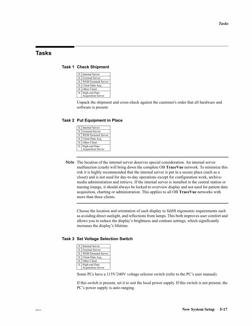
Tasks
8081318 New System Setup 5-17
Tasks
Task 1 Check Shipment
Unpack the shipment and cross-check against the customer's order that all hardware and software is present.
Task 2 Put Equipment in Place
Note The location of the internal server deserves special consideration. An internal server malfunction (crash) will bring down the complete OB TraceVue network. To minimize this risk it is highly recommended that the internal server is put in a secure place (such as a closet) and is not used for day-to-day operations except for configuration work, archive-media administration and retrieve. If the internal server is installed in the central station or nursing lounge, it should always be locked to overview display and not used for patient data acquisition, charting or administration. This applies to all OB TraceVue networks with more than three clients.
Choose the location and orientation of each display to fulfill ergonomic requirements such as avoiding direct sunlight, and reflections from lamps. This both improves user comfort and allows you to reduce the display’s brightness and contrast settings, which significantly increases the display’s lifetime.
Task 3 Set Voltage Selection Switch
Some PCs have a 115V/240V voltage selector switch (refer to the PC’s user manual).
If this switch is present, set it to suit the local power supply. If this switch is not present, the PC’s power supply is auto-ranging.
X Internal ServerX External ServerX WEB/Terminal ServerX Client Data Acq.X Other ClientX High-end Data
Acquisition Server
X Internal ServerX External ServerX WEB/Terminal ServerX Client Data Acq.X Other ClientX High-end Data
Acquisition Server
X Internal ServerX External ServerX WEB/Terminal ServerX Client Data Acq.X Other ClientX High-end Data
Acquisition Server
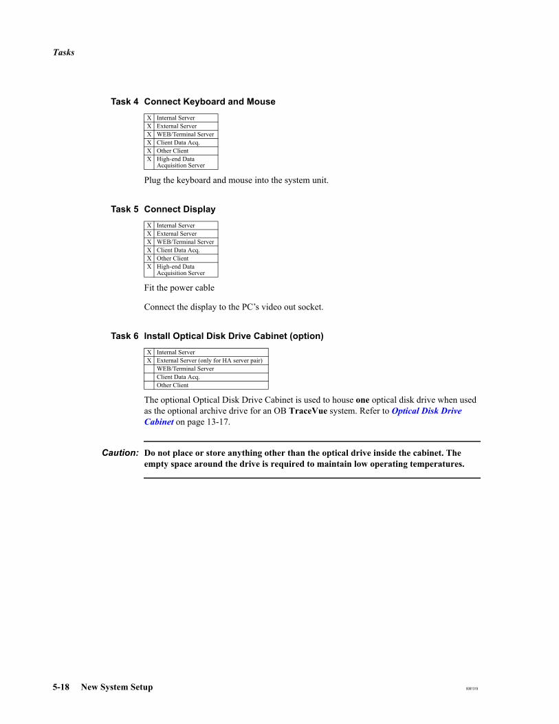
Tasks
5-18 New System Setup 8081318
Task 4 Connect Keyboard and Mouse
Plug the keyboard and mouse into the system unit.
Task 5 Connect Display
Fit the power cable
Connect the display to the PC’s video out socket.
Task 6 Install Optical Disk Drive Cabinet (option)
The optional Optical Disk Drive Cabinet is used to house one optical disk drive when used as the optional archive drive for an OB TraceVue system. Refer to Optical Disk Drive Cabinet on page 13-17.
Caution: Do not place or store anything other than the optical drive inside the cabinet. The empty space around the drive is required to maintain low operating temperatures.
X Internal ServerX External ServerX WEB/Terminal ServerX Client Data Acq.X Other ClientX High-end Data
Acquisition Server
X Internal ServerX External ServerX WEB/Terminal ServerX Client Data Acq.X Other ClientX High-end Data
Acquisition Server
X Internal ServerX External Server (only for HA server pair)
WEB/Terminal ServerClient Data Acq.Other Client
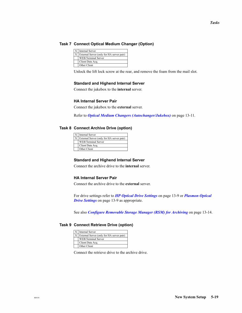
Tasks
8081318 New System Setup 5-19
Task 7 Connect Optical Medium Changer (Option)
Unlock the lift lock screw at the rear, and remove the foam from the mail slot.
Standard and Highend Internal ServerConnect the jukebox to the internal server.
HA Internal Server PairConnect the jukebox to the external server.
Refer to Optical Medium Changers (Autochanger/Jukebox) on page 13-11.
Task 8 Connect Archive Drive (option)
Standard and Highend Internal ServerConnect the archive drive to the internal server.
HA Internal Server PairConnect the archive drive to the external server.
For drive settings refer to HP Optical Drive Settings on page 13-9 or Plasmon Optical Drive Settings on page 13-9 as appropriate.
See also Configure Removable Storage Manager (RSM) for Archiving on page 13-14.
Task 9 Connect Retrieve Drive (option)
Connect the retrieve drive to the archive drive.
X Internal ServerX External Server (only for HA server pair)
WEB/Terminal ServerClient Data Acq.Other Client
X Internal ServerX External Server (only for HA server pair)
WEB/Terminal ServerClient Data Acq.Other Client
X Internal ServerX External Server (only for HA server pair)
WEB/Terminal ServerClient Data Acq.Other Client

Tasks
5-20 New System Setup 8081318
For drive settings refer to HP Optical Drive Settings on page 13-9 or Plasmon Optical Drive Settings on page 13-9 as appropriate.
See also Configure Removable Storage Manager (RSM) for Archiving on page 13-14
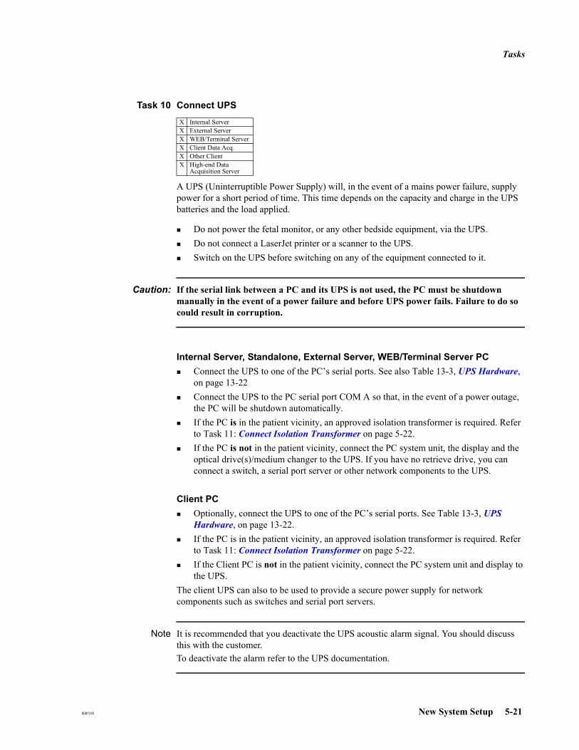
Tasks
8081318 New System Setup 5-21
Task 10 Connect UPS
A UPS (Uninterruptible Power Supply) will, in the event of a mains power failure, supply power for a short period of time. This time depends on the capacity and charge in the UPS batteries and the load applied.
Do not power the fetal monitor, or any other bedside equipment, via the UPS.Do not connect a LaserJet printer or a scanner to the UPS.Switch on the UPS before switching on any of the equipment connected to it.
Caution: If the serial link between a PC and its UPS is not used, the PC must be shutdown manually in the event of a power failure and before UPS power fails. Failure to do so could result in corruption.
Internal Server, Standalone, External Server, WEB/Terminal Server PCConnect the UPS to one of the PC’s serial ports. See also Table 13-3, UPS Hardware, on page 13-22Connect the UPS to the PC serial port COM A so that, in the event of a power outage, the PC will be shutdown automatically.If the PC is in the patient vicinity, an approved isolation transformer is required. Refer to Task 11: Connect Isolation Transformer on page 5-22.If the PC is not in the patient vicinity, connect the PC system unit, the display and the optical drive(s)/medium changer to the UPS. If you have no retrieve drive, you can connect a switch, a serial port server or other network components to the UPS.
Client PCOptionally, connect the UPS to one of the PC’s serial ports. See Table 13-3, UPS Hardware, on page 13-22.If the PC is in the patient vicinity, an approved isolation transformer is required. Refer to Task 11: Connect Isolation Transformer on page 5-22.If the Client PC is not in the patient vicinity, connect the PC system unit and display to the UPS.
The client UPS can also to be used to provide a secure power supply for network components such as switches and serial port servers.
Note It is recommended that you deactivate the UPS acoustic alarm signal. You should discuss this with the customer. To deactivate the alarm refer to the UPS documentation.
X Internal ServerX External ServerX WEB/Terminal ServerX Client Data Acq.X Other ClientX High-end Data
Acquisition Server
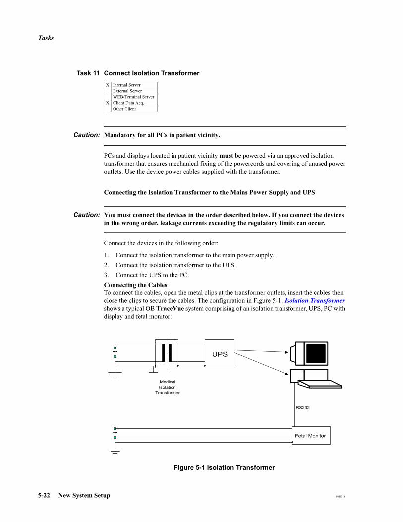
Tasks
5-22 New System Setup 8081318
Task 11 Connect Isolation Transformer
Caution: Mandatory for all PCs in patient vicinity.
PCs and displays located in patient vicinity must be powered via an approved isolation transformer that ensures mechanical fixing of the powercords and covering of unused power outlets. Use the device power cables supplied with the transformer.
Connecting the Isolation Transformer to the Mains Power Supply and UPS
Caution: You must connect the devices in the order described below. If you connect the devices in the wrong order, leakage currents exceeding the regulatory limits can occur.
Connect the devices in the following order:
1. Connect the isolation transformer to the main power supply.2. Connect the isolation transformer to the UPS.3. Connect the UPS to the PC.Connecting the CablesTo connect the cables, open the metal clips at the transformer outlets, insert the cables then close the clips to secure the cables. The configuration in Figure 5-1. Isolation Transformer shows a typical OB TraceVue system comprising of an isolation transformer, UPS, PC with display and fetal monitor:
Figure 5-1 Isolation Transformer
X Internal ServerExternal ServerWEB/Terminal Server
X Client Data Acq.Other Client
~ UPS
MedicalIsolation
Transformer
Fetal Monitor~
RS232

Tasks
8081318 New System Setup 5-23
Task 12 Connect Fetal Monitors
Fetal Monitors are connected to the OB TraceVue system
directly via PC COM Ports or through a serial port servervia Ethernet (for Avalon FM20/30/40/50)
There is no need to power a fetal monitor via either the server UPS, a client UPS, or an isolation transformer.
For Ethernet connections, Avalon FM20/30/40/50 monitors require a BOOTP Server to get a valid IP address. OB TraceVue server PCs are configured to serve both DHCP and BOOTP requests.
For details about cables and protocol converters, refer to Connecting Fetal Monitors on page 6-3.
The fetal monitor protocols do not support transmission of strings which require multibyte character sets (for languages such as Japanese and Chinese). Notes containing such characters are not sent correctly from/to the fetal monitor.
Caution: Do not connect a fetal monitor directly to the server except in a small system, that is a system with no more than 20 clients.
Caution: When connecting serial devices to the server and all four serial ports are in use, and the UPS is offline: In the event of a power failure, the UPS will power the server but the server will not shut down automatically.
In the event of a mains power failure, shut down the server manually.
Failure to do so could cause the OB TraceVue database to become corrupted.
X Internal ServerExternal ServerWEB/Terminal Server
X Client Data Acq.Other Client
X High-end Data Acquisition Server

Tasks
5-24 New System Setup 8081318
Task 13 Connect to Network
1. If there are two network interface cards installed locate the first network card: See NIC Assignment on page 19-27.
2. Plug the network cable into the socket on the back of the PC. See section Connecting to the Network on page 6-8 for details.
Task 14 Connect Second Network Card (option for Web/Terminal Server or client without data acquisition only)
1. Locate the second network card: See NIC Assignment on page 19-27.2. Connect to the card.3. Enable the second network card (default = disabled). Refer to Second Network
Interface Card on page 19-27.
Task 15 Connect Serial Port Server (option)
Refer to Installing and Setting up a Serial Port Server on page 6-13.
Task 16 Connect Modem
Refer to Modems on page 4-9 for limitations regarding the number of modems connected to OB TraceVue PCs.
Remote Trace TransmissionRefer to Setting up Remote Trace Transmission on page 6-38.
OB TraceVue Web Access through dial-up modems.Refer to Setting up Web Access Through Dial-Up Modem on page 6-38.
X Internal ServerX External ServerX WEB/Terminal ServerX Client Data Acq.X Other ClientX High-end Data
Acquisition Server
Internal ServerExternal Server
X WEB/Terminal ServerClient Data Acq.
X Other Client
X Internal ServerExternal ServerWEB/Terminal Server
X Client Data Acq.Other Client
X High-end Data Acquisition Server
X Internal ServerX External ServerX WEB/Terminal ServerX Client Data Acq.X Other Client

Tasks
8081318 New System Setup 5-25
Remote Access Support (internal and external server)See Remote Support Using Remote Desktop on page 11-3.
Fax TransmissionRefer to Setting Up Fax Transmission on page 6-39.

Tasks
5-26 New System Setup 8081318
Task 17 Switch on the OB TraceVue PC
Note Make sure the internal server PC is up and running before you start the client PCs.This allows the client to access the internal server’s CD-ROM drive if required.
1. Make sure there’s no floppy disk in the drive. At the internal server, make sure there’s no CD-ROM in the drive.
2. Switch on the optical drives (if fitted), the PC, and the display.
Logging on to Windows The Autologon option was set at the factory, so the Windows desktop loads automatically.
Task 18 Check Drive Letters
Check the drive letter assignment of the hard disk, the optical drives, and the CD-ROM drive. See Checking and Changing Drive Letters on page 19-22.
Task 19 Install Touchscreen Driver (option)
See ELO Touchscreen on page 19-31.
X Internal ServerX External ServerX WEB/Terminal ServerX Client Data Acq.X Other ClientX High-end Data
Acquisition Server
X Internal ServerExternal ServerWEB/Terminal ServerClient Data Acq.Other Client
Internal ServerExternal ServerWEB/Terminal Server
X Client Data Acq.X Other ClientX High-end Data
Acquisition Server

Tasks
8081318 New System Setup 5-27
Task 20 Set Up Soundcard (option)
The soundcard kit is pre-installed and ready to use.
Caution: The soundcard is used for audible alarming and has no other purpose.
Users must not play audio CDs since this may adversely affect audible alarming.
Do not install additional hardware for playback via the soundcard or install any additional external or internal speaker(s), or install software to control audio CD playback.
Highend PCs do not have soundcards.
Task 21 Install Optical Medium Changer Device Driver (option)
See Optical Medium Changers (Jukeboxes) on page 19-31.
Task 22 Set Time Zone, Local Time and Local Keyboard
You must set the time zone appropriate for the area in which you are installing this system.
1. On all PCs:Select the local time zone in the Control Panel.
2. Internal Server/Standalone only:Set the local date and time in the Control Panel. Do not set the local date and time at any other OB TraceVue PC. This information is received from the internal server.
3. If you have a non-US keyboard, set the language option accordingly. Refer to Regional Settings on page 19-25.
X Internal ServerX External Server
WEB/Terminal ServerX Client Data Acq.X Other Client
X Internal ServerX External Server (only for HA server pair)
WEB/Terminal ServerClient Data Acq.Other Client
X Internal ServerX External ServerX WEB/Terminal ServerX Client Data Acq.X Other ClientX High-end Data
Acquisition Server
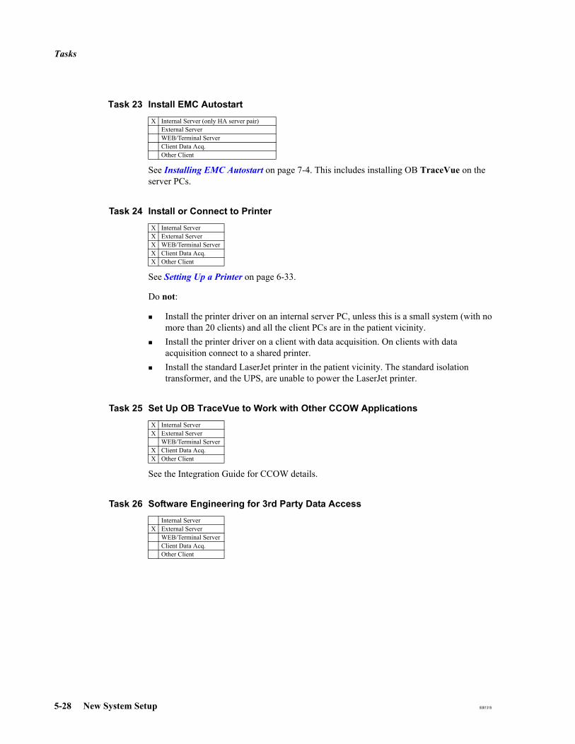
Tasks
5-28 New System Setup 8081318
Task 23 Install EMC Autostart
See Installing EMC Autostart on page 7-4. This includes installing OB TraceVue on the server PCs.
Task 24 Install or Connect to Printer
See Setting Up a Printer on page 6-33.
Do not:
Install the printer driver on an internal server PC, unless this is a small system (with no more than 20 clients) and all the client PCs are in the patient vicinity.Install the printer driver on a client with data acquisition. On clients with data acquisition connect to a shared printer.Install the standard LaserJet printer in the patient vicinity. The standard isolation transformer, and the UPS, are unable to power the LaserJet printer.
Task 25 Set Up OB TraceVue to Work with Other CCOW Applications
See the Integration Guide for CCOW details.
Task 26 Software Engineering for 3rd Party Data Access
X Internal Server (only HA server pair)External ServerWEB/Terminal ServerClient Data Acq.Other Client
X Internal ServerX External ServerX WEB/Terminal ServerX Client Data Acq.X Other Client
X Internal ServerX External Server
WEB/Terminal ServerX Client Data Acq.X Other Client
Internal ServerX External Server
WEB/Terminal ServerClient Data Acq.Other Client
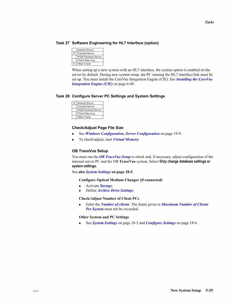
Tasks
8081318 New System Setup 5-29
Task 27 Software Engineering for HL7 Interface (option)
When setting up a new system with an HL7 interface, the system option is enabled on the server by default. During new system setup, the PC running the HL7 interface/link must be set up. You must install the CareVue Integration Engine (CIE). See Installing the CareVue Integration Engine (CIE) on page 6-49.
Task 28 Configure Server PC Settings and System Settings
Check/Adjust Page File SizeSee Windows Configuration, Server Configuration on page 19-9.To check/adjust, start Virtual Memory.
OB TraceVue SetupYou must run the OB TraceVue Setup to check and, if necessary, adjust configuration of the internal server PC and the OB TraceVue system. Select Only change database settings or system settings. See also System Settings on page 18-5.
Configure Optical Medium Changer (if connected)Activate Storage.Define Archive Drive Settings.
Check/Adjust Number of Client PCsEnter the Number of clients. The limits given in Maximum Number of Clients Per System must not be exceeded.
Other System and PC SettingsSee System Settings on page 18-5 and Configure Settings on page 18-6.
Internal ServerX External Server
WEB/Terminal ServerClient Data Acq.
X Other Client
X Internal ServerExternal ServerWEB/Terminal ServerClient Data Acq.Other Client

Tasks
5-30 New System Setup 8081318
Task 29 Configure External Server PC Settings
Note Do not configure the external server until you have completed configuring the internal server.
Check/Adjust Page File SizeSee Windows Configuration, External Database Server Configuration on page 19-12.To check/adjust, start Virtual Memory.
OB TraceVue SetupOn systems with HA server pair start OB TraceVue setup at the external server PC:
Define Archive Drive Settings (see also External Database Server (with HA Server) Configuration on page 19-13).Specify the internal server name. See Server Name (client only) on page 18-9.
You may also run the OB TraceVue Setup to check and, if necessary, adjust other settings such as use of Auto Login, or OB TraceVue Shell settings.
External Backup DeviceConnect external USB backup device at the rear panel USB port (rp5700 only).
Office ActivationFor systems that are not English, activate the Office software as described in Final Tasks on page 6-43, and install security updates as described in Installation Tasks on page 6-43.
Task 30 Configure WEB/Terminal Server PC Settings (optional)
Check/Adjust Page File SizeSee Windows Configuration, WEB/Terminal Server Configuration on page 19-14.To check/adjust, start Virtual Memory.
Terminal Services ConfigurationSee Terminal Services Configuration on page 19-19.
Internal ServerX External Server
WEB/Terminal ServerClient Data Acq.Other Client
Internal ServerExternal Server
X WEB/Terminal ServerClient Data Acq.Other Client

Tasks
8081318 New System Setup 5-31
OB TraceVue SetupOn systems with HA server pair start OB TraceVue setup at the WEB/Terminal server PC:
Specify the internal server name. See Server Name (client only) on page 18-9
Task 31 Configure Client PC Settings
Note Do not configure a client PC until you have completed configuring the internal server.
Check/Adjust Page File SizeSee Windows Configuration, Client Configuration on page 19-16.To check/adjust, start Virtual Memory.
OB TraceVue SetupOn systems with HA server pair start OB TraceVue setup at each client PC:
Specify the internal server name. See Server Name (client only) on page 18-9.
You may also run the OB TraceVue Setup to check and, if necessary, adjust other settings such as use of Auto Login, or OB TraceVue Shell settings.
Task 32 Install Word/Excel Templates (option)
For details see Installing Word and Excel Templates on page 6-46.
Task 33 Start OB TraceVue
In the Start menu click the OB TraceVue icon.
Note Do not start OB TraceVue at the WEB/Terminal server.
Internal ServerExternal ServerWEB/Terminal Server
X Client Data Acq.X Other ClientX High-end Data
Acquisition Server
X Internal ServerExternal ServerWEB/Terminal ServerClient Data Acq.Other Client
X Internal ServerX External Server
WEB/Terminal ServerX Client Data Acq.X Other ClientX High-end Data
Acquisition Server

Tasks
5-32 New System Setup 8081318
The WEB/Terminal server is dedicated to run only the terminal sessions initiated by terminal client PCs.
Task 34 Configure OB TraceVue at Internal Server PC
Finish configuring the internal server before configuring the client PCs.Each configuration screen builds on the information provided on the previous screen. Work through the configuration icons from left to right.Create at least one new superuser as the user Philips is only to give you initial access to the system and to the Philips-only configuration screen.
For details see the Instructions for Use
Note Do not use user Philips for regular operation.Never create/edit/delete patient related data when you are logged in as Philips user.
Task 35 Configure OB TraceVue at Client PCs
Do not configure a client PC until you have completed configuring the internal server.Leave OB TraceVue running at the internal server while you complete each client’s PC Configuration and Fetal Monitor Setup screens.
Task 36 Functionality Test
Perform the Functionality Test as described in Test and Inspection Matrix on page 2-6.
X Internal ServerExternal ServerWEB/Terminal ServerClient Data Acq.Other Client
Internal ServerX External Server
WEB/Terminal ServerX Client Data Acq.X Other ClientX High-end Data
Acquisition Server
X Internal ServerX External ServerX WEB/Terminal ServerX Client Data Acq.X Other ClientX High-end Data
Acquisition Server
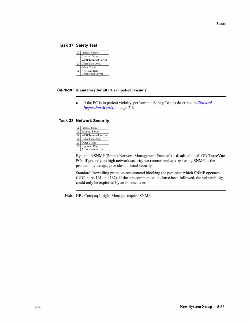
Tasks
8081318 New System Setup 5-33
Task 37 Safety Test
Caution: Mandatory for all PCs in patient vicinity.
If the PC is in patient vicinity, perform the Safety Test as described in Test and Inspection Matrix on page 2-6
Task 38 Network Security
By default SNMP (Simple Network Management Protocol) is disabled on all OB TraceVue PCs. If you rely on high network security we recommend against using SNMP as the protocol, by design, provides minimal security.
Standard firewalling practices recommend blocking the port over which SNMP operates (UDP ports 161 and 162). If these recommendations have been followed, the vulnerability could only be exploited by an intranet user.
Note HP / Compaq Insight Manager require SNMP.
X Internal ServerExternal ServerWEB/Terminal Server
X Client Data Acq.Other Client
X High-end Data Acquisition Server
X Internal ServerX External ServerX WEB/Terminal ServerX Client Data Acq.X Other ClientX High-end Data
Acquisition Server
Tasks
5-34 New System Setup 8081318
Task 39 Print and Back-Up Configuration Record
Backing-up the Configuration RecordStandalone PC: When you have finished configuring the OB TraceVue system create a configuration backup record at the server or standalone:
From OB TraceVue by clicking Configuration Backup can be made to floppy disk, hard disk or optical disk.
From Windows: Start the Configuration Backup Tool.Configuration Backup can be made to floppy disk or hard disk
Store a backup of the final configuration record in the system binder (on floppy disk).
For more information refer to Configuration Backup (Internal Server Only) on page 17-20.
Reviewing and Printing the Configuration RecordAlthough you cannot use the configuration text file to amend or set any installation or configuration parameters, you should print the file and review its content:
1. Start OB TraceVue.2. Go to System Manager’s Configuration → General.3. Click Copy of Configuration, in the ACSII Format section click Export (you may change
the default name of the configuration text file before clicking Export).4. Start NotePad, open the configuration text file.5. Print the file.6. Close NotePad.7. Review the printed file with the System Manager. Store a print of the final
configuration record with the configuration backup floppy disk.
Task 40 Print out PC Installation Record
Each OB TraceVue PC automatically maintains its own installation record. This record contains information such as the setup type (for example, network server), the installation path and system options. To review the installation record:
Go to OB TraceVue Support → Installation Record.
By default, the installation record opens as a .txt file in NotePad. You may print the installation record from NotePad.
X Internal ServerExternal ServerWEB/Terminal ServerClient Data Acq.Other Client
X Internal ServerX External ServerX WEB/Terminal ServerX Client Data Acq.X Other ClientX High-end Data
Acquisition Server

Tasks
8081318 New System Setup 5-35
Task 41 Disable Flexible Disk Drives
The floppy disk drives on all OB TraceVuePCs are disabled to prevent users attempting to run their own software on OB TraceVue.
To change flexible disk drive settings:
1. Restart the PC.2. Press F2 when prompted during power up to activate the BIOS SETUP.3. At BIOS paragraph Security Features enable or disable the following values:.
Start From Flexible DiskFlexible Disk Drives
For a reinstallation of the system, drive A has to be enabled.
Task 42 Prepare Backup of External Database
Remind the System Manager about setting up a backup schedule.
See also the System Administration and Configuration Guide.
X Internal ServerX External ServerX WEB/Terminal ServerX Client Data Acq.X Other ClientX High-end Data
Acquisition Server
Internal ServerX External Server
WEB/Terminal ServerClient Data Acq.Other Client
Tasks
5-36 New System Setup 8081318
Task 43 License Balancing (optional)
Note This is only required if there you are setting up more than one WEB/Terminal Server PC.
Factory installed OB TraceVue Web Client licenses may not suit the customer’s needs. Determine the total number of assigned client licenses, discuss the requirements with the customer and distribute the licenses as needed.
Determine Number of Client Licenses
Perform the following steps on all WEB/Terminal Server PCs and summarize the number of licenses.
1. Start the Terminal Services Configuration tool: Administrative Tools → Terminal Services Configuration.
2. In the left pane select Connections, in the right pane select OBTV Tcp.3. From the menu select Action → Properties.4. Choose the Network Adapter tab. The maximum number of connections is equivalent to
the number of configured Client Licenses.
Discuss Client License Distribution with CustomerWhen discussing the license distribution with the customer, consider the following issues:
How many users should be able to connect to which OB TraceVue system at the same time? This gives you the number of licenses that should be assigned to each system. The total number of licenses for all systems must equal the number of licenses ordered.For best performance licenses should be evenly distributed among the WEB/Terminal Server PCs of a single system.
Distribute Client Licenses
Client licenses must be adjusted at the following two places:
Terminal Services Configurationa. Start the Terminal Services Configuration tool as described in Determine Number
of Client Licenses on page 5-36.b. Adjust the maximum number of connections. The maximum number is 12.
Windows Client Access Licensesa. Open Licensing.b. In the Licensing Mode dialog select Per Device or Per User.
Internal ServerExternal Server
X WEB/Terminal ServerClient Data Acq.Other Client

Tasks
8081318 New System Setup 5-37
Task 44 Activate License Server
Use the Terminal Server License Manager to activate Terminal Server License Server. For detailed information about Terminal Service licensing refer to the help in the License Manager.
Note Without activation of the License Server the OB TraceVue Web Access will be deactivated after a grace period of 90 days.
Perform the following steps to activate the License Server:
1. Start the Terminal Server License Manager: Administrative Tools → Terminal Services Licensing.
2. Select the appropriate server (activation status: not activated) in the list of available license servers.
3. From the menu choose Action → Activate Server.4. The Licensing Wizard guides you through the process of activating the License Server.
Choose Telephone as connection method and call the Microsoft license clearing house for your region. The wizard will provide you with the appropriate telephone number.
5. Provide the clearing house with the information below:
6. The clearing house will provide you with the activation key that is required for activating the license server and finishing the wizard.
Note If activation by telephone fails (error message when finishing license server activation process) restart the Licensing Wizard and choose World Wide Web as connection method.
The activation must be performed for all OB TraceVue WEB/Terminal Server PCs.
Internal ServerExternal Server
X WEB/Terminal ServerClient Data Acq.Other Client
Licensing Program: OtherProduct ID: The product ID is displayed in the wizard.Company: Name of the institution where the license server is installed.Organizational Unit: Optional.Last Name: Last name of the responsible person of the institution.First Name: First name of the responsible person.Phone: Phone number of the responsible person.

Tasks
5-38 New System Setup 8081318
Task 45 Install Terminal Server Client Access Licenses
Access of PCs to OB TraceVue Web Access requires separate purchase and activation of Terminal Service Client Access Licenses (TSCALs). The licenses must be ordered through a Microsoft sales channel. It is the sole responsibility of the customer to order and activate these licenses. Refer to the help of the Terminal Server License Manager for details of the Terminal Server licensing model.
Note Clients can access OB TraceVue Web Access without TSCAL for a grace period of 120 days. After that period a valid TSCAL has to be installed for these clients.After activating new TSCALs in the license server clients should immediately connect to OB TraceVue Web Access to initiate automatic transfer of the license. This prevents unintended usage of the licenses by other clients.
Internal ServerExternal Server
X WEB/Terminal ServerClient Data Acq.Other ClientHigh-end Data Acquisition Server
Tasks
8081318 New System Setup 5-39
Task 46 Change Passwords
For security purposes, it is recommended to change the following passwords:
Windows Users (at all PCs)AdministratorOBTV Administratoruser
OB TraceVue User: Philips
Caution: Note the passwords and store in a safe place.If all administrator passwords are lost you need to reinstall Windows.If the Philips password is lost see Restoring the OB TraceVue Philips Password on page 18-10.
Task 47 Power Switch Cover
To help avoid the accidental uncontrolled shutdown of a PC, a plastic cover is provided which protects the power switch on the PC front panel. Not for rp5700 PC.
To fit the power switch cover1. Clean the surface around the PC’s power switch.2. Stick the power switch cover in place so its hole is over the center of the power switch.
To operate the power switchTo operate the switch, push a stiff wire (such as a bent paper-clip) into the hole in the center of the switch cover.
Task 48 Store System Documentation and Backups
Store all license sheets, password sheets, configuration printouts, the installation record, and emergency repair disks in a safe location.
X Internal ServerX External ServerX WEB/Terminal ServerX Client Data Acq.X Other ClientX High-end Data
Acquisition Server
X Internal ServerX External ServerX WEB/Terminal ServerX Client Data Acq.X Other Client
WEB Clients
5-40 New System Setup 8081318
WEB Clients
Starting a WEB Client
1. At a PC connected to the hospital network, start the Windows Internet Explorer1.2. In the Address Bar enter http://<ip address>2 or http://<server name>3.3. Click Start OB TraceVue Web Access.4. Select between small resolution or full screen resolution.Terminal server client sessions have a fixed display resolution of 800*600 (small.htm), 1024*768 (large.htm) or full screen (full.htm).
Real-Time WEB Client
Installation 1. At a PC connected to the hospital network start the Windows Internet Explorer1.2. Enter http://<ip address>/install.htm or http://<server name>/install.htm.3. Click one of the links in the Web page to download the Software Only Setup.4. In the File Download dialog click Run this program from its current location to start
TVWebSetup.exe.5. Follow the instructions on screen.
Check Real-TimeConnection
To check correct installation of a real-time client:
1. Start an OB TraceVue Web client (see Starting a WEB Client).2. Click on the alarming symbol and select the sounds you want to test.
Note If the alarming symbol is not visible check log file of the web client.
MS Vista for WEB TS Clients
OB TraceVue E.00.22 or higher supports WEB TS clients running Microsoft Vista. For details see the instructions displayed during the setup of real time alarming below. If the customer is not using real time alarming, you will not see the screenshot below, and no further configuration is required.
1. Windows NT, 2000, 2003 Server, XP: you must have Windows administrator rights if you start OB Trace-Vue Web Access for the first time.
2. IP address of WEB/Terminal server external NIC.3. WEB/Terminal server must be registered in the locating service (e.g. DNS) of hospital network.
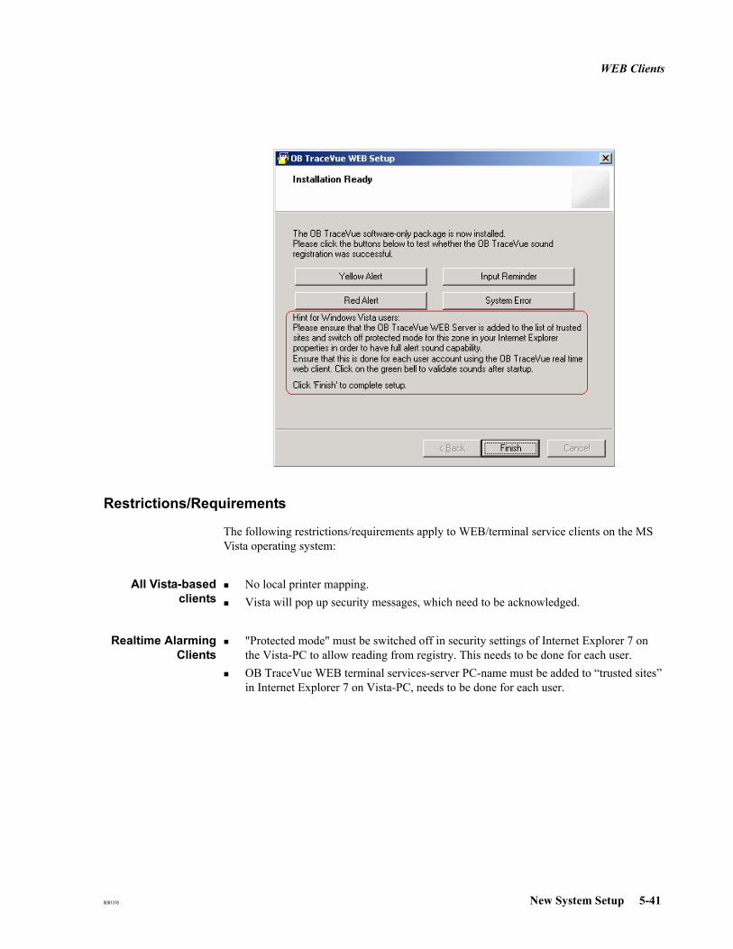
WEB Clients
8081318 New System Setup 5-41
Restrictions/Requirements
The following restrictions/requirements apply to WEB/terminal service clients on the MS Vista operating system:
All Vista-basedclients
No local printer mapping.Vista will pop up security messages, which need to be acknowledged.
Realtime AlarmingClients
"Protected mode" must be switched off in security settings of Internet Explorer 7 on the Vista-PC to allow reading from registry. This needs to be done for each user.OB TraceVue WEB terminal services-server PC-name must be added to “trusted sites” in Internet Explorer 7 on Vista-PC, needs to be done for each user.

WEB Clients
5-42 New System Setup 8081318
Manually Installing ActiveX Control of OB TraceVue Web Client
This step does not apply to Windows XP with SP3 and Vista.
This manual procedure should be used if a customer does not permit automatic download of ActiveX components to the web client. Temporary administrative rights are required on the web client for the installation.
1. On the OB TraceVue terminal server extract the files msrdp.ocx and msrdp.inf from the file c:\inetpub\wwwroot\msrdp.cab.In Explorer, double-click on the .cab file to view the content.Right-click on each file and select extract.Extract the files to e.g. C:\Temp.
2. Copy these two files into the directory <Windows Directory>\Downloaded Program Files of the Web client, using the command prompt. For example: copy msrdp.* C:\WINDOWS\Downloaded Program Files
3. Register the ActiveX control using regsvr32.exe. For example: regsvr32 “C:\WINDOWS\Downloaded Program Files\msrdp.ocx"
Installing OB TraceVue Real Time Alarming Software Without Connecting to Terminal Server
This manual procedure should be used if a customer does not want to connect to the terminal server in order to setup the real-time alarming function on the terminal service client. Temporary administrative rights are required on the web client for the installation.
1. Copy c:\inetpub\wwwroot\tvwebsetup.exe from OB TraceVue Web/Terminal Server to local directory of Web client.
2. Execute tvwebsetup.exe on Web client, follow instructions on screen.
8081318 Setup Details 6-1
6Setup Details
Introduction This chapter gives details on the following setup tasks:
Installing a Client on a Cart (Mobile Client).
Connecting Fetal Monitors.
Connecting to the Network.
Installing and Configuring Remote LAN Clients.
Installing and Setting up a Serial Port Server.
Setting Up a Printer.
Setting Up Remote Connectivity.
Installing and Configuring Microsoft Office 2007.
Installing Word and Excel Templates
Installing the CareVue Integration Engine (CIE)
The detailed descriptions in this chapter are referred to from Chapter 5, New System Setup.
Installing a Client on a Cart (Mobile Client)A client PC can be cart mounted with a Series 50 IX, XM, or XMO (M1350 A/B/C) Fetal/Maternal monitor.
Refer to the Carts Equipment Note M1325-9001D, Cart CX.
There is no provision for using the installed mouse; a touchscreen or lightpen option is required.
Do not cart mount an OB TraceVue client PC to a Model 80300A Mobile Cart. The CRT display is too heavy, and mounting brackets are not available.
Do NOT connect a printer to a cart mounted client.
Telemetry Unit
If telemetry is used, fix the M1310A receiving module to the top of the Cart CX, then fit the display to the top of the receiving module using the mounting brackets provided with the cart.
Installing a Client on a Cart (Mobile Client)
6-2 Setup Details 8081318
Client UPS
You must power the PC system unit and display via a UPS and an isolation transformer. The client UPS and isolation transformer fit onto the lowest shelf of a Cart CX, and the PC system unit on the shelf above.
Make the power connections as follows:
Mains ↔ Isolation Transformer ↔ UPS ↔ PC/Display
Do not power the fetal monitor via a UPS.
Do not attempt to leave OB TraceVue running at a client (supported by the client UPS) while the cart is disconnected from the LAN and moved to a new location.
If you move a mobile client into a storage room, reconnect the UPS to the power supply to recharge the UPS batteries. Never leave the UPS disconnected, because the batteries will drain down. Make sure that the system manager understands this.
Configuration
After starting OB TraceVue this client needs to be configured as Mobile. Refer to the Instructions for Use for configuration instructions.
Moving the Cart
Whenever the mobile client is moved to a different location you need to assign the new bed to the client PC.
To shut down a mobile client
1. Exit OB TraceVue. You must exit OB TraceVue before moving the cart, disconnecting from the LAN, or turning off the client.
2. Go to Start → Shutdown, select Shut down.
3. When prompted that it is safe to do so, turn off the computer.
4. Disconnect the power and LAN cables.
To start a mobile client
1. Connect the power and LAN cables.
2. Turn on the PC.
3. Log on to Windows as user (if no automatic login is setup).
4. Log on to OB TraceVue.
5. At the Fetal Monitor Setup screen verify the Fetal Monitor connections and select the correct bed labels. Assign the new bed to the new location.
6. A cart mounted PC is configured as a mobile client. The OB TraceVue startup screen for a mobile client is the Fetal Monitor Setup screen.
Connecting Fetal Monitors
8081318 Setup Details 6-3
Connecting Fetal Monitors
This section tells you how to connect fetal monitors to OB TraceVue.
Fetal monitors are connected to
the COM ports of the client PCs
the COM ports of the server PC (small systems only)
the COM ports of a standalone PC
the COM ports of a serial port server.
M1350, M1351/53 and Avalon FM20/FM30/40/50 Monitors
M13501, M1351/53, and Avalon FM20/30/40/50 fetal monitors are connected directly, using only the RS-232 FM-cable.
Other Fetal Monitors
All other fetal monitor cables come as a cable unit consisting of:
Small cable from Fetal Monitor to converter.
Converter box.
RS-232 cable to COM port or Wallplate SUB-D.
Network Type
Decentralized In a decentralized installation, client PCs are located in patient rooms next to the fetal monitors. The RS-232 cable from the fetal monitor connects directly to a COM port on the client PC.
Centralized In a centralized installation, client PCs are located at a central location next to the server. RS-232 cable from the FM cable kit plugs into the 9pin SUB-D wall plate (male) in the patient room. Wall cabling represent RS-232 connection (M1380x #K40).
Use the PC cable provided with the wall cabling option (M1380x #K41) to connect from wallplate 9pin SUB-D (female) at the central location to the PC COM port. This cable is wired straight through, do not use a crossed RS-232 cable. See the Site Preparation Guide for wall cable drawings.
1. Requires RS-232 Digital Systems Interface.

Connecting Fetal Monitors
6-4 Setup Details 8081318
Connecting Four Fetal Monitors
The PC must be fitted with an additional RS-232 serial interface card to support four fetal monitors.
The PCI RS-232 serial interface card provides two additional COM ports, both 9 pin.
Connecting More than Four Fetal Monitors
More than 4 fetal monitors can be connected using one or more serial port servers. For details see Installing and Setting up a Serial Port Server on page 6-13.
Protocol Conversion
OB TraceVue accepts the digital signal protocol used by Series 50 and Avalon FM20/FM30/40/50 fetal monitors. Other fetal monitor types, including others manufactured by HP/Agilent/Philips, use different cable connectors and signal protocols. To connect these to OB TraceVue you must use the appropriate adapter cables and protocol converters. A separate converter is required for each fetal monitor. Refer to Appendix A for details of how to use the protocol conversion kits, and data tables for supported fetal monitors and mounting instructions.
Mounting the Converter Box
Mount the converter box onto the fetal monitor housing using the velcro patch provided.

Connecting Fetal Monitors
8081318 Setup Details 6-5
Hewlett-Packard / Agilent / Philips Fetal Monitors
The following information will help you to connect standard HP/Agilent/Philips monitors. See the Site Preparation Guide for full details, including ordering information, for the system interface requirements and cable drawings.
M1351/53 Fetal Monitor
Use the OB TraceVue connection cable M1380-61613, (M1380x option K13), which has a 24pin connector to the monitor. Do not use the 9pin connector.
The RS-232 interface requires at least software version A.02.02 and M1353-69531(E).
Figure 6-1 OB TraceVue connection on M1351/53
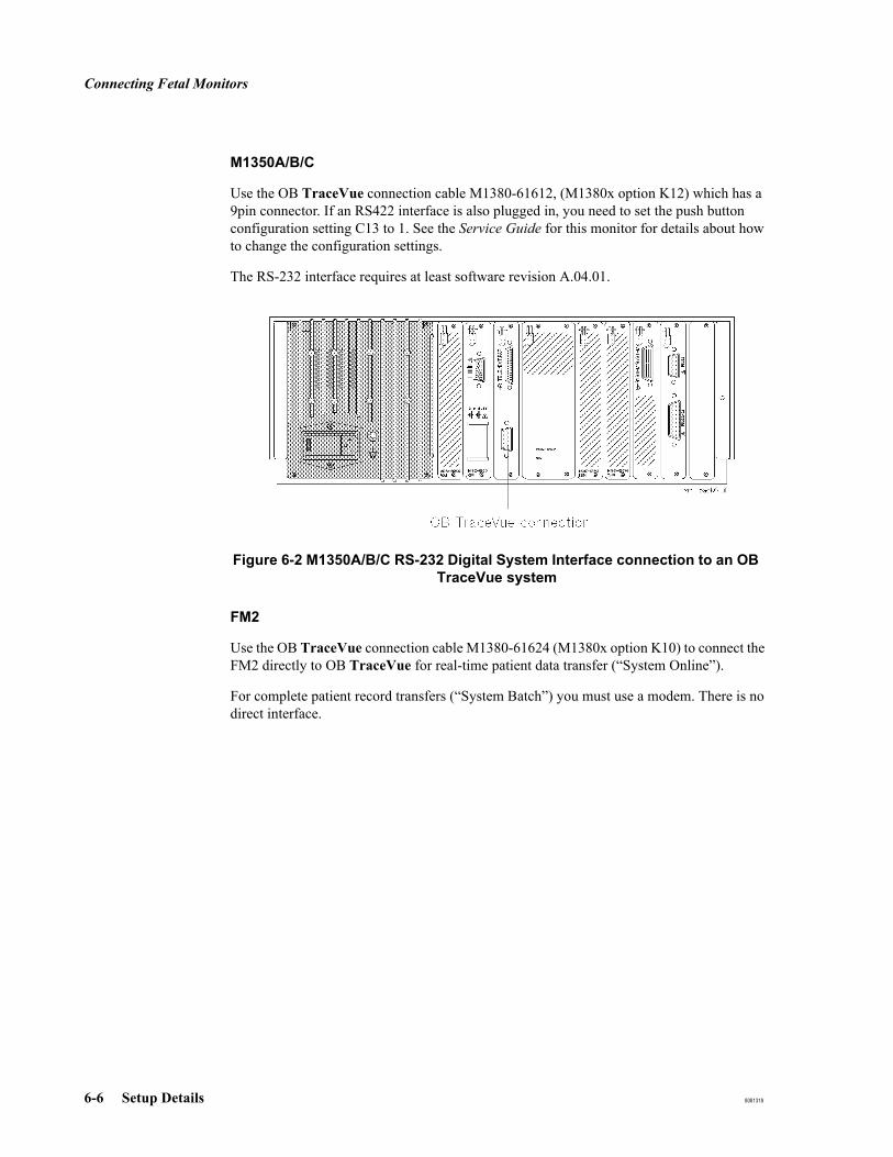
Connecting Fetal Monitors
6-6 Setup Details 8081318
M1350A/B/C
Use the OB TraceVue connection cable M1380-61612, (M1380x option K12) which has a 9pin connector. If an RS422 interface is also plugged in, you need to set the push button configuration setting C13 to 1. See the Service Guide for this monitor for details about how to change the configuration settings.
The RS-232 interface requires at least software revision A.04.01.
Figure 6-2 M1350A/B/C RS-232 Digital System Interface connection to an OB TraceVue system
FM2
Use the OB TraceVue connection cable M1380-61624 (M1380x option K10) to connect the FM2 directly to OB TraceVue for real-time patient data transfer (“System Online”).
For complete patient record transfers (“System Batch”) you must use a modem. There is no direct interface.

Connecting Fetal Monitors
8081318 Setup Details 6-7
Avalon FM20, FM30, FM40 and FM50
Use the OB TraceVue connection cable M1380-61612 (M1380x option K12) to connect via the RS-232 port. The interface connections are underneath the monitor. For connection to OB TraceVue, the Avalon FM requires:
Avalon FM software revision C.00 or greater for RS232 connection.
Avalon FM software revision D.00 or greater for LAN connection.
RS-232 interface connection LAN connection
Connecting to the Network
6-8 Setup Details 8081318
Connecting to the NetworkThe installation and maintenance of network cabling to a professional standard is the customer’s responsibility. This section describes how PCs in an OB TraceVue installation are connected to form a Local Area Network (LAN).
Note See also Integration Guide, chapter Network Guide.
Network Connections
The OB TraceVue PCs are connected to switches to form a LAN with star topology.
OB TraceVue PCs may be connected to the hospital network. Routing ports to the hospital backbone are preferred. Alternatively VLAN can be used.
In a decentralized installation, client PCs are located close to the bedside, so the wall cabling is the LAN connection. In centralized installations, much of the wall cabling is from fetal monitors to client PCs located, for example, at the Central Station.
When the FSE installs OB TraceVue all wall cabling must be in place. If additional clients are purchased, extensions to the LAN and any other fixed cabling must be in place before the FSE re-installs OB TraceVue.
Switches
The following switches are supported:
HP ProCurve Switch 2312 (12 port unmanaged 10/100 Base-TX autosensing switch)
HP ProCurve Switch 2324 (24 port unmanaged 10/100 Base-TX autosensing switch)
Detailed information on how to install these products is provided in the appropriate installation guide delivered with the switch.
Network Specifications
Networks withSwitch
The OB TraceVue Internal Server PC must be connected directly to the switch (100 Mbps). It is recommended to connect the External Server PC to the same switch.
It is possible to connect Avalon fetal monitors directly to the OB TraceVue switch.
Network devices can be connected directly to a switch port.Switches can be cascaded.Cascading switches can be used to extend the distance between OB TraceVue server and clients.
Serial Port Servers The network between the serial port server and the host PC must not be routed (same network segment).
See also Connect the Serial Port Server on page 6-16.

Connecting to the Network
8081318 Setup Details 6-9
Cable Specifications
All the cable used in the LAN must be twisted pair with at least 2 twists per foot or 6 twists per meter. This cable is also known as “EtherTwist”.
The customer must ensure cables are within the maximum length permitted for LAN cabling, including the lengths of cable between faceplates and hardware.
Do not use flat cable in the LAN, even if the cable length is very short.
100 Base-T CableTesting
Use a Wire Test Instrument to determine whether a cable is suitable for a Type 100Base-T network by testing attenuation, crosstalk, continuity and burst noise. Refer to the CAT-5 Specification
Table 6-1 Cable Type and Length
Connection Type
Cable must conform to
specifications defined in:
Cable Type Length Limits
100Base-TX IEEE 802.3u Type 100Base-TX stan-dard
Category 5 or 6 100Ω Unshielded Twisted Pair.
RJ-45 modular plugs.
• 100m switch ⇔ switch
100Base-FX
Switch only:for transceiver connection (optional)
ITU-T G.651 and ISO/IEC 793-2 Type A1b or A1a respectively.
62.5/125μm or 50/125μm (core/cladding) diameter, graded - index, multimode fiber-optic cables.Fitted with SC connectors.
2km1 for full duplex con-nections (the 100Base-FX transceiver only operates in full duplex mode).
1. 1.68 miles
RS-232 9-pin/25-pin SUB-D connec-tor.
8/16-port serial Port Server:
RJ45-10 / 9-pin SUB-D con-nectors.
100m
Attenuation 11.5dB attenuation between 5MHz and 10MHz(10dB in cable, 1.5dB in connectors)
Pair to Pair ≥30.5dB at 5MHz
Crosstalk ≥26dB at 10MHz
Connecting to the Network
6-10 Setup Details 8081318
Cabling a LAN
To connect a PC to the LAN cable
When connecting a PC to a LAN cable, ensure that the latch on the RJ-45 connector is clicked in place correctly.
Caution: When failing to secure the LAN cable properly the client may shut down or crash, and loss of data may occur.
1. Plug one end of the EtherTwist cable into the RJ-45 socket on the network card in the PC. Push the connector in as far as possible.
2. Gently pull the cable to test whether the catch is properly clicked in. If the connector cannot be pulled out, it is firm; continue with step 4. If it can be released by pulling, continue with step 3.
3. Take a closer look at the RJ-45 socket on the PC. If the hole is too close to the edge of the PC housing the latch on the connector cannot click in. To alleviate the problem:
a. Turn off the power.
b. Remove the PC housing.
c. Loosen the screw holding down the network adapter.
d. Move the network adapter until as much of the RJ-45 socket is uncovered to let the connector click in properly. If necessary, use a moderate amount of force.
e. Tighten the screw holding down the network adapter.
f. Replace the PC cover.
4. If the client is in a cart you must provide some form of strain relief for the LAN cable on the PC side, for example, a tie-wrap.
To connect a PC to a Switch
Ensure that mains power to all equipment is switched off before you start. See the Site Preparation Guide for wall cable drawings.
1. Connect the LAN cable to the PC (see To connect a PC to the LAN cable on page 6-10).
2. Plug the other end of the EtherTwist cable into an RJ-45 port on the LAN faceplate. For a centralized installation, plug it into the switch RJ-45 port directly.
3. Connect the switch to the faceplates.
4. Repeat the previous steps to connect the server, clients, printer (with JetDirect card).

Installing and Configuring Remote LAN Clients
8081318 Setup Details 6-11
Installing and Configuring Remote LAN ClientsA Remote LAN Client is an OB TraceVue PC that is connected to an OB TraceVue server that does not reside in the same physical network.The Remote LAN Client can be an OB TraceVue client, external server, or WEB/Terminal server PC. Remote LAN Clients operates in the same way as a “normal” OB TraceVue client.
Limitations and Prerequisites
Described in the Integration Guide, chapter Network Guide. All requirements and pre-requisites must be fulfilled.
Installation and Configuration
Note It is not permitted to install and configure a 2nd NIC in the OB TraceVue internal server and external server.
Prepare Network Hospital IT department should set access control lists in a way that allows only the Remote LAN Clients to access the Internal and External OB TraceVue servers. Router ports must be configured as OB TraceVue gateway.
Connect the OB TraceVue switch to the gateway (router port).
Prepare InternalServer PC
1. Assign the default gateway (IP address of router port).Control Panel → Network Protocols and Dial up Connections → Local Area Connections → Properties → TCP/IP Protocol
2. Start OB TraceVue Setup.Select Only change database settings or system settings.Select Do not change system settings.Configure IP Addresses of Servers for Remote Clients: Enter the IP addresses of the NICs that are connected to the hospital network.
3. Restart OB TraceVue.
Prepare RemoteLAN PC
1. If required, install the operating system1. See Windows New Installation, Installation from Internal Server PC on page 19-7. Do not install the OB TraceVue software automatically.
2. Assign IP address, subnet mask, and default gateway (IP address of the connected router port). Do not use DHCP.Control Panel → Network Protocols and Dial up Connections → Local Area Connections → Properties → TCP/IP Protocol
1. If the PC does not have a CD-ROM drive temporarily connect the PC to the same network segment as the OB TraceVue server PC.

Installing and Configuring Remote LAN Clients
6-12 Setup Details 8081318
3. Name resolution:Open %windir%\system32\drivers\etc\hosts and add the following line:
<IP Address of Internal Server PC> <Internal Server PC Name>Example: 172.16.1.2 FR71900243It is also possible to use name resolution provided by hospital servers (e.g. WINS).
4. Connect the NIC to the hospital network.
Test the Connection 1. At the Server DOS prompt enter
ping <Client IP address>In case of problems try ping <OBTV default gateway> and ping <HIS default gateway>
tracert <Client IP address>A route to the client must be found.
2. At the Client DOS prompt enter
ping <Server IP address>In case of problems try ping <HIS default gateway> and ping <OBTV default gateway>tracert <Server IP address>A route to the server must be found.ping <Server name>The Server PC should reply properly. This verifies correct name resolution.
Install OB TraceVueat the Remote LAN
PC
Ensure that there is an established network connection from the remote LAN client PC to the internal server PC before starting OB TraceVue setup. This can be done by opening a network drive to the internal server (do not select reconnect at startup).
1. Install OB TraceVue from the local CD-ROM or at the internal server PC. The “setup” directory is on the server share. \\server\TV2\setup
2. Perform a complete new OB TraceVue setup.
Note: You need to enter the server PC name manually; you cannot browse.
Note If the external IP addresses of the internal server or external server PC changed after Remote LAN Client installation you must reinstall OB TraceVue at the remote LAN client.
If setup finishes but reports an error when it tries to connect to the OB TraceVue server database try to ping the database:
dbping -c "CommLinks=tcpip{HOST=<Server IP Address>};ENG=<Internal Server PC Name>I"
(The last argument of this command is the DB service name, which is the internal server PC name appended with the uppercase letter I)
A connection to the database server should be established without error messages.
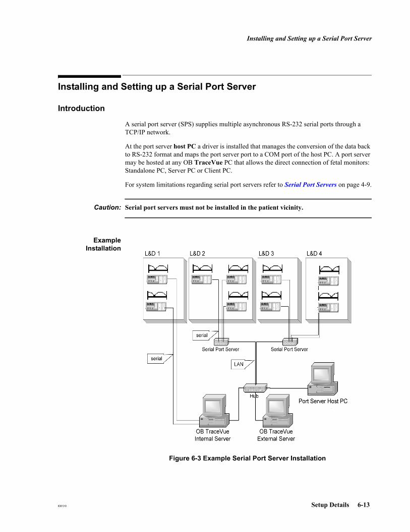
Installing and Setting up a Serial Port Server
8081318 Setup Details 6-13
Installing and Setting up a Serial Port Server
Introduction
A serial port server (SPS) supplies multiple asynchronous RS-232 serial ports through a TCP/IP network.
At the port server host PC a driver is installed that manages the conversion of the data back to RS-232 format and maps the port server port to a COM port of the host PC. A port server may be hosted at any OB TraceVue PC that allows the direct connection of fetal monitors: Standalone PC, Server PC or Client PC.
For system limitations regarding serial port servers refer to Serial Port Servers on page 4-9.
Caution: Serial port servers must not be installed in the patient vicinity.
ExampleInstallation
Figure 6-3 Example Serial Port Server Installation
Installing and Setting up a Serial Port Server
6-14 Setup Details 8081318
Installation Tasks To install serial port servers you must perform the following steps:
Note You must log onto Windows as Windows administrator.You must not host different series of NPort servers (DE-303 / DE-304 / DE-308 series and 5610 series) at one PC simultaneously.
Step 1. Configure Host PC Network Settings.
Step 2. Physically Connect Port Server to the network.
Step 3. Configure Port Server Network Settings.
Step 4. Install Software:NPort Server DE-303 / DE-304 / DE-308 seriesNPort Server 5610 series.
Step 5. Check Serial Port Server Firmware Revisions.
Step 6. Configure Serial Port Server (access control / ports):NPort Server DE-303 / DE-304 / DE-308 seriesNPort Server 5610 series
Repeat step 2, 3, 5 and 6 for each additional serial port server connected to the host PC.
Step 7. Configure OB TraceVue (serial ports, beds) at the host PC.Repeat step 1 through 6 for each additional host PC.
Step 8. Connect Fetal Monitors to the serial port servers and Check Fetal Monitor to Bed Connection.
Documentation It is strongly recommended to use the tables at the end of this section for documentation. Store the configuration sheets with all your other system documentation.

Installing and Setting up a Serial Port Server
8081318 Setup Details 6-15
Host PC Network Settings
Serial port server host PCs must not operate as DHCP clients. They must have a fixed IP address.
Therefore, when hosting a serial port server at an OB TraceVue client PC you must change the network configuration of the client PC.
Caution: Do not change the network settings of the OB TraceVue internal server PC.
Only change network settings at OB TraceVue client PCs that act as serial port server host.
Start Network and Dial-up Connection → Local Area Connection → Properties → Internet Protocol (TCP/IP) → Properties.
IP Address whenInstalling MultipleSerial Port Server
When installing multiple serial port server it is strongly recommended to assign IP address ranges that reflect the connection between host PC and port server:
Table 6-1 Host PC Network Settings
IP Address Recommended range:172.16.201.1 .. 172.16.201.254
Netmask 255.255.0.0
Default gateway none
DNS none
WINS none
172.16.201.10172.16.200.10 .. 172.16.200.19
first host PCserial port servers hosted by first host PC
172.16.201.20172.16.200.20 .. 172.16.200.29
second host PCserial port servers hosted by second host PC
172.16.201.30172.16.200.30 .. 172.16.200.39
third host PCserial port servers hosted by third host PC
... ...

Installing and Setting up a Serial Port Server
6-16 Setup Details 8081318
Connect Port Server
Connect the SerialPort Server
The serial port server can be connected
To the network via a network switch. It is possible to connect the serial port server to the hospital network. In such a case the serial port server and the serial port server host PC must be connected to the same network segment (not routed).
Directly to the network interface card of an OB TraceVue host PC using a cross-wired Ethernet cable (only one serial port server).
Caution: The serial port server must be connected to a 100 Mbps network1.
Note You must use a fail-safe power supply for the serial port server and for the network switches (e.g. UPS).If the network connection between OB TraceVue PC and the serial port server has been interrupted you should reboot the OB TraceVue PC to reconnect.
Maximum CableLength
To minimize side effects on the serial connection, the serial cable should be as short as possible, but the serial port server must not be installed in patient vicinity. The length is 100m per network node, plus 100m for RS232 connection to the fetal monitor.
See also Cable Specifications on page 6-9.
1. The network between serial port server, host PC, and internal server must be 100Mbps.

Installing and Setting up a Serial Port Server
8081318 Setup Details 6-17
Port Server Network Settings
Network Settings Serial port servers must have a fixed IP address. The following network settings must be used:
Configuring SerialPort Server
Network Settings
Depending on the serial port server model you must use different methods when initially configuring the network settings. Once the port server has an IP address that can be reached in the OB TraceVue network you can use telnet with all models.
LCD Panel
a. Use the buttons on top of the port server to configure network settings and name.
b. Follow the instructions given in the port server’s user manual.
Telnet Console (no LCD panel available)
a. Open a command prompt window, type telnet <IP address> where <IP address> is the IP address of the serial port server. Set the serial port server name and configure network settings.
b. Follow the instructions given in the port server’s user manual (see IP Address Configuration).
c. If the IP address of the serial port server is not within the OB TraceVue network address range (172.16.x.y) you must temporarily change the IP address of the OB TraceVue PC in order to access the serial port server.Example: If the default IP address of the serial port server is 192.168.n.m change the IP address of the OB TraceVue PC to 192.168.x.y (change only the first two numbers; avoid duplicate IP addresses). Do not change the subnet mask (255.255.0.0).
d. Restore the IP address of the OB TraceVue PC.
e. Document the IP address and host PC of the serial port server using the table Serial Port Server Installation Documentation on page 6-29.
Table 6-2 Serial Port Server Network Settings
IP Address Recommended range:172.16.200.1 .. 172.16.200.254
Netmask 255.255.0.0
DHCP disable

Installing and Setting up a Serial Port Server
6-18 Setup Details 8081318
IP Address whenInstalling MultipleSerial Port Server
See IP Address when Installing Multiple Serial Port Server on page 6-15.
Verify the NetworkConnection
At an OB TraceVue PC:
Open a command prompt window.
Type: ping <IP Address>where <IP Address> is the IP address of the serial port server.
The ping command must not report lost packets or time-outs. Otherwise check the network connection and the configuration of the serial port server.
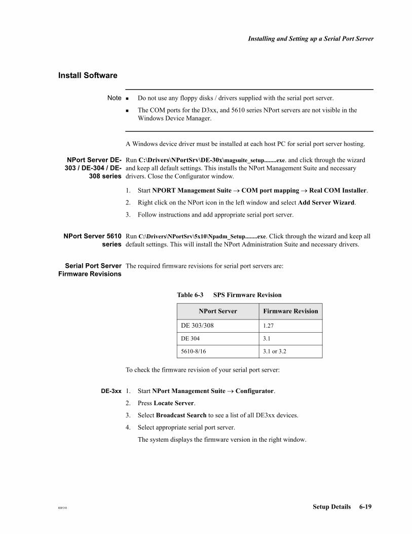
Installing and Setting up a Serial Port Server
8081318 Setup Details 6-19
Install Software
Note Do not use any floppy disks / drivers supplied with the serial port server.
The COM ports for the D3xx, and 5610 series NPort servers are not visible in the Windows Device Manager.
A Windows device driver must be installed at each host PC for serial port server hosting.
NPort Server DE-303 / DE-304 / DE-
308 series
Run C:\Drivers\NPortSrv\DE-30x\magsuite_setup........exe. and click through the wizard and keep all default settings. This installs the NPort Management Suite and necessary drivers. Close the Configurator window.
1. Start NPORT Management Suite → COM port mapping → Real COM Installer.
2. Right click on the NPort icon in the left window and select Add Server Wizard.
3. Follow instructions and add appropriate serial port server.
NPort Server 5610series
Run C:\Drivers\NPortSrv\5x10\Npadm_Setup........exe. Click through the wizard and keep all default settings. This will install the NPort Administration Suite and necessary drivers.
Serial Port ServerFirmware Revisions
The required firmware revisions for serial port servers are:
To check the firmware revision of your serial port server:
DE-3xx 1. Start NPort Management Suite → Configurator.
2. Press Locate Server.
3. Select Broadcast Search to see a list of all DE3xx devices.
4. Select appropriate serial port server.
The system displays the firmware version in the right window.
Table 6-3 SPS Firmware Revision
NPort Server Firmware Revision
DE 303/308 1.27
DE 304 3.1
5610-8/16 3.1 or 3.2

Installing and Setting up a Serial Port Server
6-20 Setup Details 8081318
5610-8/16 1. Start NPort Administration Suite → NPort Administrator.
2. Right click on Configuration in the left function window.
3. Select Broadcast Search.
4. Double click the appropriate serial port server to open the Configuration window, where the firmware version is visible.
Upgrading NPortServer Firmware for
DE-303/308/304
If you need to update the firmware:
1. Start NPORT Management Suite → COM port mapping → Real COM Installer.
2. Select NPORT SERVER in the left window.
3. Select the firmware upgrade button.
4. Browse to the folder C:\Drivers\NPortSrv\Firmware and select the appropriate firmware for your NPort server.
5. Start the upgrade.
Upgrading NPortServer Firmware for
5610-8/16
If you need to update the firmware:
1. Start NPORT Administration Suite → NPort Administrator.
2. Press the Search button.
3. Select NPort Server.
4. Right click on Configuration in the left function window.
5. Select Upgrade Firmware.
6. Browse to the folder C:\Drivers\NPortSrv\Firmware and select the appropriate firmware for your NPort server.
7. Start the upgrade.
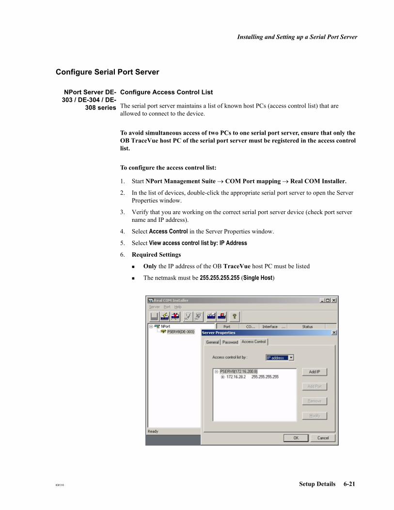
Installing and Setting up a Serial Port Server
8081318 Setup Details 6-21
Configure Serial Port Server
NPort Server DE-303 / DE-304 / DE-
308 series
Configure Access Control List
The serial port server maintains a list of known host PCs (access control list) that are allowed to connect to the device.
To avoid simultaneous access of two PCs to one serial port server, ensure that only the OB TraceVue host PC of the serial port server must be registered in the access control list.
To configure the access control list:
1. Start NPort Management Suite → COM Port mapping → Real COM Installer.
2. In the list of devices, double-click the appropriate serial port server to open the Server Properties window.
3. Verify that you are working on the correct serial port server device (check port server name and IP address).
4. Select Access Control in the Server Properties window.
5. Select View access control list by: IP Address
6. Required Settings
Only the IP address of the OB TraceVue host PC must be listed
The netmask must be 255.255.255.255 (Single Host)

Installing and Setting up a Serial Port Server
6-22 Setup Details 8081318
Configure Ports
The port configuration determines which ports of the serial port server(s) are mapped to which COM ports on the host PC.
1. Check COM ports:
To ensure that there is no conflict between COM ports, check whether serial port server ports [Moxa Communication Port x (COM y)] conflict with built-in COM ports [Communications Port (COM z)] or other port server ports.
2. Check COM port mapping and configure port server ports:
In case of duplicate COM ports or if you want to change COM port assignment for other reasons:
a. Start NPort Management Suite → COM Port mapping → Real COM Installer.
b. In the list of devices, click on the appropriate serial port server.
In the right window, the system displays the COM port mapping.
c. To change port settings for all ports select the appropriate port, and right click and select Port Properties.
d. In the Port Properties dialog adjust the port numbers. Do not change any other settings.
e. Ensure that the port server ports do not conflict with build-in COM ports.f. Document port settings using the table Serial Port Server Host PC Installation
Documentation on page 6-31.
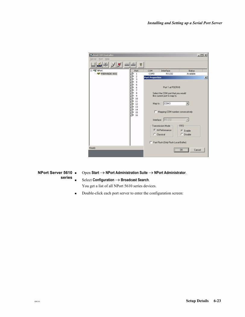
Installing and Setting up a Serial Port Server
8081318 Setup Details 6-23
NPort Server 5610series
Open Start → NPort Administration Suite → NPort Administrator.
Select Configuration → Broadcast Search.You get a list of all NPort 5610 series devices.
Double-click each port server to enter the configuration screen:
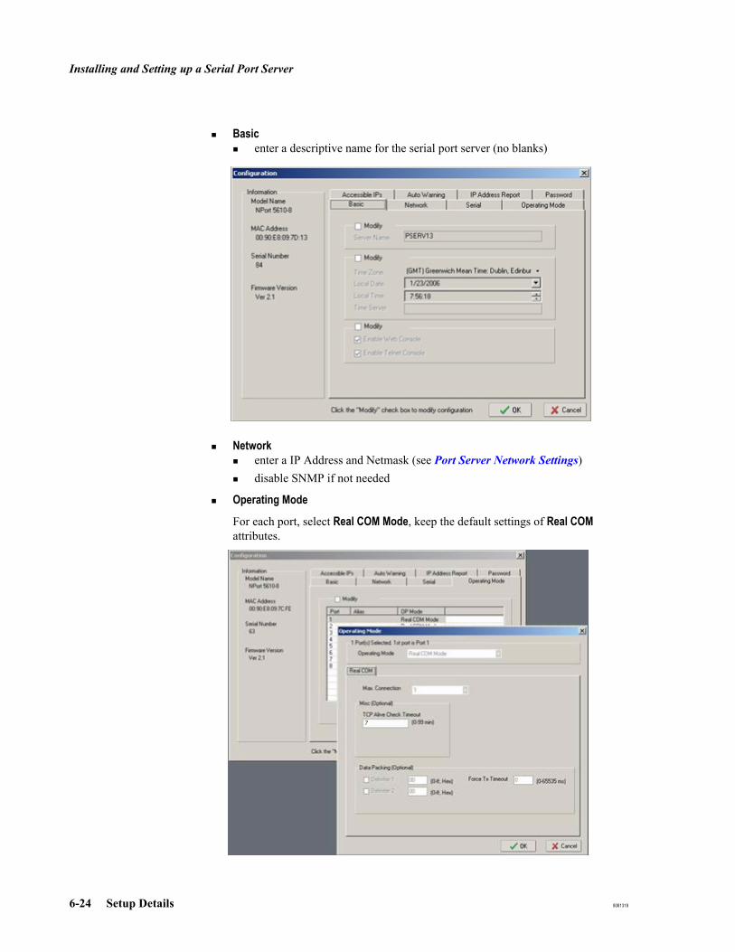
Installing and Setting up a Serial Port Server
6-24 Setup Details 8081318
Basicenter a descriptive name for the serial port server (no blanks)
Network enter a IP Address and Netmask (see Port Server Network Settings)disable SNMP if not needed
Operating Mode
For each port, select Real COM Mode, keep the default settings of Real COM attributes.
7
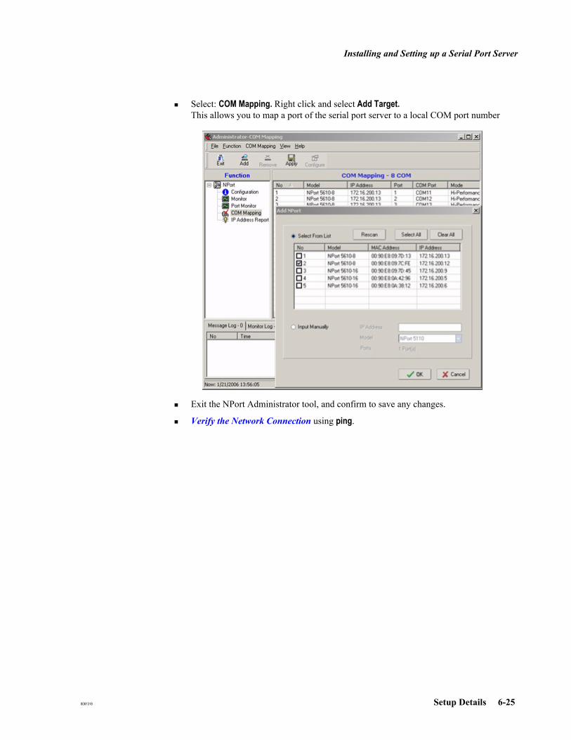
Installing and Setting up a Serial Port Server
8081318 Setup Details 6-25
Select: COM Mapping. Right click and select Add Target.This allows you to map a port of the serial port server to a local COM port number
Exit the NPort Administrator tool, and confirm to save any changes.
Verify the Network Connection using ping.

Installing and Setting up a Serial Port Server
6-26 Setup Details 8081318
Configure OB TraceVue
1. Verify Basic Serial Connection
Start the FMSpy (see Fetal Monitor Spy (FMSpy) on page 16-23) and select a mapped COM port. Start data transmission for this connection and check that data can be received.
2. Setup Serial Ports
Run the OB TraceVue setup on the host PC for the serial port server. In the setup program the COM ports can be selected as usual.
Run the OB TraceVue Setup:Only change database settings or system settingsDo not change system settings (no password required).Check Define port settings.
If not all COM ports are available verify the driver settings and check the access control lists. Restart the PC and run setup again.
3. Assign Beds
a. Start OB TraceVue.
b. In Fetal Monitor Setup assign the available ports to OB TraceVue beds. COM 1 .. COM4 are listed as FM 1 (A) .. FM 4 (D), all other ports as FM x.
Connect Fetal Monitors
Depending on the serial port server model different connectors are required for the RS-232 cables: See the Site Preparation Guide for pin assignments and cable layout is
Use adapter M1380-60610 for every fetal monitor connected to a 5610 SPS. Please refer to the Site Preparation Guide for the complete wiring scheme.
Check Fetal Monitor to Bed Connection
Perform the test described in Chapter 2, Safety, Performance Serial Port Server on page 2-9.
Table 6-4 Serial Port Server RS-232 Connectors
Port Server
Number of Ports
RS-232 Connector Remarks
5610-8 8 RJ45-8
5610-16 16 RJ45-8
DE304 4 9 pin SUB-D standard RS232 cable
DE308 8 RJ45-10
DE303 16 RJ45-10

Installing and Setting up a Serial Port Server
8081318 Setup Details 6-27
Using the Serial Port Server at a Different PC
NPort Server DE-303 / DE-304 / DE-
308 series
1. On the old host PC
a. Select Start → NPort Management Suite → Uninstall.
b. Run OB TraceVue setup to remove the serial port server ports.See also Configure OB TraceVue on page 6-26, step 2.
c. Start OB TraceVue and check port to bed assignment. See also Configure OB TraceVue on page 6-26, step 3.
2. On the new host PC
a. Install the device driver on the new host PC. See Install Software, NPort Server DE-303 / DE-304 / DE-308 series on page 6-19.
b. Check the access control list and check the port mapping of the serial port server. See NPort Server DE-303 / DE-304 / DE-308 series on page 6-21.
c. Configure OB TraceVue. See Configure OB TraceVue on page 6-26.
d. Check Fetal Monitor → bed connection. Perform the test described in Chapter 2, Safety, Performance Serial Port Server on page 2-9.
NPort Server 5610series
1. On the old host PC
a. Open Start → NPort Administration Suite → NPort Administrator.Select COM Mapping, select the serial port server and Remove Target.
b. Run OB TraceVue setup to remove the serial port server ports.See also Configure OB TraceVue on page 6-26, step 2.
c. Start OB TraceVue and check port to bed assignment. See also Configure OB TraceVue on page 6-26, step 3.
2. On the new host PC
a. Install the software (see Install Software, NPort Server 5610 series on page 6-19)
b. Configure the serial port server (see NPort Server 5610 series on page 6-23) and check the port mapping.
c. Configure OB TraceVue. See Configure OB TraceVue on page 6-26.
d. Check Fetal Monitor → bed connection. Perform the test described in Chapter 2, Safety, Performance Serial Port Server on page 2-9.
Replacing a Serial Port Server
NPort Server DE-303 / DE-304 / DE-
308 series
To replace a serial port server you must perform the following steps:

Installing and Setting up a Serial Port Server
6-28 Setup Details 8081318
Step 1. Physically connect the new port server device to the network. See Connect Port Server on page 6-16
Step 2. Configure the network settings of the serial port server. See Port Server Network Settings on page 6-17. The new serial port server must use the same IP Address as the defect port server. See Serial Port Server Installation Documentation on page 6-29.
Step 3. Configure the serial port server (access control / ports). See Configure Serial Port Server: NPort Server DE-303 / DE-304 / DE-308 series on page 6-21. The new must be hosted at the same host PC as the defect port server. See Serial Port Server Host PC Installation Documentation on page 6-31.
Step 4. Connect the fetal monitors to the serial port servers and check the connections.
NPort Server 5610series
To replace a serial port server you must perform the following steps:
Step 1. Physically connect the new port server device to the network. See Connect Port Server on page 6-16
Step 2. Open Start → NPort Administration Suite → NPort Administrator. Select COM Mapping, select the old serial port server and Remove Target.Select Configuration → Specify by IP Address. Enter the IP Address of the new serial port server device.
Step 3. Configure the serial port server (access control / ports). See Configure Serial Port Server: NPort Server 5610 series on page 6-23. The new must be hosted at the same host PC as the defect port server. See Serial Port Server Host PC Installation Documentation on page 6-31.
Step 4. Connect the fetal monitors to the serial port servers and check the connections.

Installing and Setting up a Serial Port Server
8081318 Setup Details 6-29
Serial Port ServerInstallation DocumentationList all serial port servers and their OB TraceVue host PC.
Date: ____________________
Table 6-5 Serial Port Server Installation Documentation
Port Server OB TraceVue Host PC Location/Remarks
Name IP Address Name IP Address
___.___.___.___ ___.___.___.___
___.___.___.___ ___.___.___.___
___.___.___.___ ___.___.___.___
___.___.___.___ ___.___.___.___
___.___.___.___ ___.___.___.___
___.___.___.___ ___.___.___.___
___.___.___.___ ___.___.___.___
___.___.___.___ ___.___.___.___
___.___.___.___ ___.___.___.___
___.___.___.___ ___.___.___.___
___.___.___.___ ___.___.___.___
___.___.___.___ ___.___.___.___
___.___.___.___ ___.___.___.___
___.___.___.___ ___.___.___.___
___.___.___.___ ___.___.___.___
___.___.___.___ ___.___.___.___
___.___.___.___ ___.___.___.___
___.___.___.___ ___.___.___.___
___.___.___.___ ___.___.___.___
___.___.___.___ ___.___.___.___

Installing and Setting up a Serial Port Server
6-30 Setup Details 8081318
This page intentionally left blank.

Installing and Setting up a Serial Port Server
8081318 Setup Details 6-31
Serial Port Server Host PCInstallation DocumentationUse one page for each serial port server host PC. List all serial port servers hosted at the PC and all port server ports mapped to local COM ports.
Date: ____________________
PC Name: ____________________ Location:____________________
IP Address: ____________________
Table 6-6 Serial Port Server Host PC Installation Documentation
Port Server Mapped to
COMRemarks
Name Port

Installing and Setting up a Serial Port Server
6-32 Setup Details 8081318
This page intentionally left blank.
Setting Up a Printer
8081318 Setup Details 6-33
Setting Up a PrinterYou can connect one printer to the system.
Note Additional printers can be used, but setup, driver installation, and support is the customer's responsibility. Alternative printers (different model than shipped with OB TraceVue) can also be used. Because of the different drivers this is considered 3rd-party integration as described in the Integration Guide. The customer is responsible for setup, driver installation, support and integration test of alternative printers.
You can connect a printer to:
A parallel printer port.The network by using an HP JetDirect card.
Note Do not connect a printer to a client PC in the patient vicinity.
Windows Printer Types
Local Printer A local printer is installed on one PC.
The PC runs the print spooler for the local printer and communicates with the printer using the parallel port or the network. A local printer can be shared so it can be accessed from other PCs. Local printers are PC specific (available to all users registered to the PC).
Network Printer A network printer is a shared printer.
On the PC that runs the print spooler for the network printer it appears as local printer. For all other PCs the printer can be accessed via the network. It is sufficient to connect to that printer. Shared printers are user specific (need to be added for each user).
Note Shared printing has an impact on the performance of the PC running the shared printer spooler if several print jobs are running.If possible you should install the shared printer on a client without data acquisition or on the External server PC.The print-server PC must be up and running 100% of the time.Avoid installing the shared printer on the internal server PC.
Setting Up a Printer
6-34 Setup Details 8081318
General Printer Setup Procedures
Note You must log on as Windows administrator to install a printer.
Installing a LocalPrinter
1. Log on as an administrator.
2. Run the driver from the OB TraceVue application software CD H:\Drivers\Printer\HP
3. The HP Universal Printing Installer runs automatically. If for any reason it is necessary to do this manually, run Install.exe in the unzipped directory.
4. Choose Traditional Mode and continue clicking Install.
5. The Printer Wizard opens.
6. Select Local Printer attached to this computer and click Next.
7. Follow the on-screen instructions for selecting a printer port.
8. On the Software selection window, HP Universal Printing is marked. Click Next.
9. Add a share name for the printer and, passing through all on-screen instructions, click Finish.
10. Files are copied, and on successful completion you see the confirmation Printer was successfully installed.
11. Click Finish to close Setup.
Connecting to aShared Printer
1. Start the Printer Wizard.
2. Select Network printer.
3. Follow the on-screen instructions.
Connect PrinterUsing TCP/IP
1. Reserve IP Address on the DHCP Server PC (if the printer is configured for DHCP)
To prevent the DHCP server offering different IP addresses to the printer the printer IP address has to be reserved. To do this:
a. Open Administrative Tools → DHCP.
b. Check if the printers' IP address is in the list of Address Leases.
c. Select Reservation → New Reservation...
d. Enter the information (see printer configuration printout):Reservation Name: <Host Name>IP Address: <IP Address>MAC Address: <MAC Address>Description: Printer
2. Log on as an administrator.

Setting Up a Printer
8081318 Setup Details 6-35
3. Run the driver from the OB TraceVue application software CD H:\Drivers\Printer\HP.
4. Unzip the file.
The HP Universal Printing Installer runs automatically. If, for any reason, it is necessary to do this manually, run Install.exe in the unzipped directory.
5. Choose Traditional Mode and continue clicking Install.
6. The Printer Wizard opens.
7. Select Local Printer attached to this computer.
8. Deselect Automatically detect and install my Plug and Play printer and click Next.
9. Select Create a new port and Standard TCP/IP Port as the type of port and click Next.
10. A new wizard opens. Click Next.
11. Enter Printer Name or IP Address of the printer you want to connect and Port Name, then click Next.
12. On the next window, click Finish.
13. On the software selection window, HP Universal Printing is marked. Click Next.
14. Enter Printer Name, Share name (optional; use this only if you want to share the printer in the network). Location, and Comment. Click Next.
15. Select Yes if you want to print a test page.
16. Click Finish to complete Setup.
17. Files are copied; on successful completion you see the confirmation message Printer was successfully installed.
18. Click Finish to close Setup.
Setting up a Printer 1. Right-click the printer you want to set up, select Printing Preferences.
2. To set the appropriate paper size click the Advanced... button.
Install the shared printer as Administrator on the terminal server; setting up a network share is not required.
Deleting a Printer 1. Right-click the printer you want to delete.
2. Select Delete.
3. Acknowledge the warning message with yes.
Sharing an ExistingPrinter
1. Right-click the printer you want to share, select Sharing...
2. Enter an appropriate Share Name.

Setting Up a Printer
6-36 Setup Details 8081318
Printer Connected to a PC’s Parallel Port
Note At the PC to which the printer is connected, make sure the parallel printer port is enabled and unlocked. Refer to the BIOS Settings for the PC model you are installing.
Follow the procedures described in General Printer Setup Procedures on page 6-34. When creating a printer select the LPT1 printer port.

Setting Up a Printer
8081318 Setup Details 6-37
Printer Connected to the Network using a HP JetDirect Card
Overview To use a network printer you must
Install Network Printer Hardware.
Add and Configure the JetDirect Port.
After that follow the procedures described in General Printer Setup Procedures on page 6-34. When creating a printer select the appropriate network printer port.
Installation andConfiguration
1. Install the Network Printer Hardware
a. Install the JetDirect card in the printer.
b. Refer to the User Manual supplied with the printer to print the printer’s configuration. This includes information you will need later, such as the JetDirect Card’s LAN HW (hardware) address.
c. Connect the printer to a network port on the switch using Ethertwist cable with RJ-45 connectors. This uses one port on the switch, which is no longer available for connection to another switch, PC, or network printer.
2. Configure Printer Configuration Menu
Set/confirm the following protocol settings in the printer configuration menu. You must do this online at the printer.
3. Print Configuration Settings
At the printer go to Printer Menu → Information Menu → Print Configuration
Connect PrinterUsing TCP/IP
For details on connecting a printer using TCP/IP, refer to Connect Printer Using TCP/IP (see page 6-34).
TCP/IP set to on (enabled)
IPX/SPX set to off (disabled)
AppleTalk set to off (disabled)
Setting Up Remote Connectivity
6-38 Setup Details 8081318
Setting Up Remote Connectivity
This section details setting up remote access to OB TraceVue for remote trace transmission, remote support purposes, and for transmitting faxed traces.
Note The customer site requires at least one dedicated analog (not digital) telephone line. It is recommended to have a second phone line installed near the PC where the remote support modem is installed for voice communication between the Response Center and customer.
It is recommended that you use a modem with a connection speed of at least 28k.
Setting up Remote Trace Transmission
Connect the modem(s).
Do not install a modem device driver.
Run OB TraceVue setup. Define Remote Monitor port settings. See also Fetal Monitor Connections (Ports) on page 18-7.
Note Do not connect remote trace transmission modems to a serial port server.
Setting up Web Access Through Dial-Up Modem
At the WEB/Terminal server:Install the modem and configure an incoming connection.
At the WEB client:Install the modem and configure an outgoing connection.
For details see Installing a Modem on page 6-40.
To start an OB TraceVue WEB client:
At the WEB client PC
establish a connection to the WEB/Terminal server (dial)
start Windows Internet Explorer
enter http://<ip address> or http://<server name>
Setting up Remote Access Support
Refer to Remote Support Using Remote Desktop on page 11-3.

Setting Up Remote Connectivity
8081318 Setup Details 6-39
Setting Up Fax Transmission
Install the modem.
When installing a modem a fax printer driver is installed automatically. Use the “Fax” printer from OB TraceVue to fax traces or documents.
Configure the Fax In the Printers dialog right-click the Fax printer, select Properties.To set the appropriate paper size click the Printing Preferences... button
Setting Up Remote Connectivity
6-40 Setup Details 8081318
Installing a Modem
Note You must log on as Windows administrator to install a modem.
You must install and configure a modem device in order to use
OB TraceVue Web Access (through dial-up modem)Remote Access Support Fax transmission
Note You must not install and configure a modem device driver for modems used with remote trace transmission.
Adding the ModemDevice
1. Connect modem to PC with modem serial cable and turn modem on.2. Open Control Panel, select Phone and Modem options.3. Select the Modem tab.4. Select Add...5. Follow the instructions on screen.
Configure theModem
1. Open Control Panel, double-click Phone and Modem options.2. Select your country/region location and enter your area code and outside line dialing
code.
Configure OutgoingConnections
(Windows 2003)
By creating an outgoing connection, a computer can connect to a remote access server. An outgoing connection is required for Fax transmission, Remote Access Support (support office) or WEB client.
1. Open Network and Dialup Connections (Control Panel).2. Click Make New Connection to start the Network Connection Wizard.3. Select Dial-up to private network.4. Follow the instructions on screen.
User name: user Password Security on page 3-1 for the default user password.5. Enable Routing and Remote Access Service (see Enable Routing and Remote
Access Service on page 6-41.

Setting Up Remote Connectivity
8081318 Setup Details 6-41
Configure IncomingConnections
By creating an incoming connection, a computer can act as a remote access server. An incoming connection is required for OB TraceVue Web Access (through dial-up modem) at the WEB/Terminal server and for Remote Access Support (customer’s site).
1. Open Network Connections (Control Panel).2. Click Create a New Connection to start the Network Connection wizard.3. Click Setup an advanced Connection.4. Select Accept incoming connection.5. Select required device for incoming connection.6. Select Allow virtual private connections.7. Users allowed to connect: user.8. Follow the instructions on screen.9. When setting up remote connections, make sure that the firewall is turned off.
Enable Routing andRemote Access
Service
1. Open Administrative Tools (Control Panel).2. Select Services.3. Select Routing and Remote Access, set the Startup Type to Automatic.
Installing and Configuring Microsoft Office 2007
6-42 Setup Details 8081318
Installing and Configuring Microsoft Office 2007
Caution: Microsoft Office must not be installed at the internal server PC.
Installing Microsoft Office Small Business 20071
Caution: Do not install any Office version other than 2007.
Do not mix Office versions within one OB TraceVue System.
Previous Office versions MUST be uninstalled.
Installing and operating Microsoft Office 2007 on a Web/Terminal Server requires you to be compliant with MS Licensing for Terminal Servers. For details please refer to Microsoft Corp.
Manual Installation
1. Uninstall previous Office versions.
2. Logon as Windows administrator.
3. Start the MS Office Small Business 2007 installation:
WEB/Terminal Server PC
MS Office must be installed from CD using Add/Remove Programs. Do not use the Explorer to start Setup.
Other PCs:
Start Setup on the MS Office CD. Follow the on-screen instructions.
4. Select Customize installation.
5. Select Word and Excel to Run from My Computer. Disable all other Office applications.
6. Select Office Shared Features and Office Tools to Run from My Computer.
7. Expand Microsoft Office Excel. Make sure that .NET Programmability Support is selected to Run from My Computer.
8. Expand Microsoft Office Word. Make sure that .NET Programmability Support is selected to Run from My Computer.
9. Accept the default path to install Office in File Location.
10. Click Install Now.
1. For Taiwan, Japan, and China, this must be Office Standard 2007.

Installing and Configuring Microsoft Office 2007
8081318 Setup Details 6-43
11. If the installation requests Check the Web... and Delete installation files, make sure that neither is selected.
12. Click Close to finish installation.
Final Tasks
After the office installation you must perform the following steps:
1. Apply custom settings by starting CustomConfig<your Office Edition>.MSP from \Utilities\MSOffice2007 on the OB TraceVue Application Installation CD-ROM, where <your Office Edition> is the custom settings file that matches your Office 2007 edition. Execution of the script is only required once (that is, it does not have to be performed not for various users). Choose the appropriate file from:
CustomConfig_SmallBusiness_Retail.MSP
CustomConfig_Standard_Retail.MSP
CustomConfig_Enterprise.MSP
CustomConfig_Professional.MSP
CustomConfig_SmallBusiness_OEM.MSP
2. Activate Office:
a. Logon to Windows as OBTV Administrator.
b. Start Word.
c. Enter User Name and Initials when prompted.
d. Office activation is depending on license model. Follow the on-screen instructions.
e. Disable all privacy options when prompted.
f. Close Word.
Installation Tasks
Install Service Pack The English service pack is available on the OB TraceVue Application Installation CD-ROM (\UtilitieMSOffice2007\Service Pack). You can down load localized versions of the service pack and Microsoft updates from the Microsoft WEB server. You should change the language as required for the customer, scroll down the page and download the appropriate file. In the quoted file names below, "XYZ" indicates you should select the appropriate language code.
http://www.microsoft.com/downloads/details.aspx?displaylang=en&FamilyID=9ec51594-992c-4165-a997-25da01f388f5
Download: office2007sp1-kb936982-fullfile-XYZ.exe
Installing MicrosoftOffice Updates
Install updates from \Utilities\MSOffice2007\Updates on the Application Installation CD-ROM. Run apply.cmd to install all updates at once.
Installing and Configuring Microsoft Office 2007
6-44 Setup Details 8081318
Additional updates may be available from Microsoft. For details please refer to the Integration Guide.
Checking Microsoft Office Version
1. Start Microsoft Word and Excel.
2. Click the Microsoft Office Button and then Word/Excel options.
3. Click Resources and check the version information. The required program versions have the identification codes shown here:
Microsoft Office Word 2007 (12.0.6311.5000) SP1
Microsoft Office Excel 2007 (12.0.6300.5000) SP1
MSO (12.0.6213.1000)
All three revisions have to match. They reflect the patch level (SP and security updates) as included on the OB TraceVue software media. If any of the revisions is later than those given above, an integration test is required. For details please refer to the Integration Guide.
Check for Publisher's Certificate Revocation List
This is a user specific setting and must be performed for all Windows users granted access to MS Office, such as OBTV Administrator, user, and the terminal services logon user (if you want to allow access to MS Office on Web client PCs).
Microsoft permits checking for a publisher's certificate revocation list. If the customer's internet connection does not allow this service to connect to the relevant server, this might cause delay in opening certificated MS-Office documents when Macro Security is enabled. Depending on the customer's infrastructure, the following steps might resolve this issue:
1. Open Internet Explorer to set the default internet connection settings.
2. If no full and permanent internet connection is available, disable the update of the certificate revocation list CRL:
a. Select Tools → Internet Options and click the Advanced tab.
b. Under the Security section of the tree view control, uncheck "Check for publisher's certificate revocation".
c. Close Internet Explorer.
Troubleshooting
Use this procedure if Word reports or Excel statistics do not print.
Check .NET Programmability Support
To check .NET Programmability:

Installing and Configuring Microsoft Office 2007
8081318 Setup Details 6-45
1. Start Control Panel → Administrative Tools → Microsoft .NET Framework Configuration.
2. Select My Computer → Assembly Cache.
3. Select Tasks → View List of Assemblies in the Assembly Cache.
4. Check if the following assemblies are available:
Microsoft.Office.Interop.Excel
Microsoft.Office.Interop.Word
Install .NET Programmability Support
Prerequisites: Microsoft Office must be installed.
1. Logon as Windows administrator.
2. Start the MS Office 2007 Setup.
WEB/Terminal Server PC.
The MS Office installation must be started using Add/Remove Programs. Select Microsoft Office, click Change.
Other PCs:
Start Setup on the MS Office CD
3. Select Add or Remove Features.
4. Click Continue.
5. Expand Microsoft Office Excel. Make sure that .NET Programmability Support is selected to Run from My Computer.
6. Expand Microsoft Office Word. Make sure that .NET Programmability Support is selected to Run from My Computer.
7. Click Continue.

Installing Word and Excel Templates
6-46 Setup Details 8081318
Installing Word and Excel Templates
Overview
Prerequisites OB TraceVue must be installed with the External Database option.Microsoft Office must be installed, see Installing and Configuring Microsoft Office 2007. You must be able to access the templates share (<server>\OBTVTemplates). The templates share is C:\Tv2_Templates at the internal server PC.
Directory Structure The initial installation of OB TraceVue installs templates and other files required for Word documents and Excel statistics in the C:\Tv2_Templates directory on the Internal Server PC. This directory is shared as OBTVTemplates.
..\codetemplates, macros and binary files for template supportdo not modify the contents of this directory
..\factorydirectory for factory-provided templatescontents may be overwritten or modified by future OB TraceVue releasesdo not modify the contents or store customized templates in this directory
..\customerdirectory for templates accessible by the printing moduledirectory for customized templatescontents will not be overwritten or modified by future OB TraceVue releases
..\maternal directory for templates used in maternal mode
..\newborn directory for templates used in newborn mode
..\..\excel Excel templates (*.xlt)
..\..\word Word templates (*.dot)
..\..\..\auto files in print in the background
..\..\..\manual files open Excel or Word

Installing Word and Excel Templates
8081318 Setup Details 6-47
Template RevisionsTemplate Latest layout change released
with OB TraceVue Rev. ... Comments
ReportsAdmission.dot F.00.10Antepartum.dot F.00.10Discharge.dot F.00.10DischargeRecord.dot F.00.10DischargeSummary.dot F.00.10FCAssessByTime.dot D.01.00FCAssessByType.dot D.01.00GYN All.dot new with F.00.10GYN Visit.dot new with F.00.10Inpatient Postpartum.dot F.00.10Labor and AlternateDelivery.dot F.00.10Labor and Delivery.dot F.00.10Labor&Delivery.dot F.00.10ObstetricAdmit.dot F.00.10PatientsPregnancyEpisodes.dot D.01.00PostpartumVisit.dot D.01.00PostpartumVisits.dot F.00.10ProgressNotes.dot D.01.00Teaching.dot D.01.00NST.dot E.00.00NST Overview.dot E.00.00NurseryAdmission.dot F.00.10NurseryDischarge.dot F.00.10NurseryFCAssessByTime.dot D.01.00NurseryFCAssessByType.dot D.01.00Empty TemplatesTVReportM.dot New with D.01.00TVReportN.dot New with D.01.00EpTVReportM.dot New with D.01.00EpTVReportN.dot New with D.01.00Statistics Admission Log.xlt E.00.00ChalkboardM Log.xlt E.00.00 Does not support the two chalk-
board columns that are defined in the value table editor (\\Maternal\Chalkboard).
ChalkboardN Log.xlt E.00.00 Does not support the two chalk-board columns that are defined in the value table editor (\\New-born\Chalkboard).
Delivery Log.xlt F.00.10Discharge Log.xlt E.00.00Fetal Death Log.xlt E.00.00Labor&Delivery Log.xlt F.00.10Live Birth Log.xlt F.00.10NurseryAdmission Log.xlt E.00.00NurseryDischargeLog.xlt E.00.00Obstetric Statistics.xlt E.00.00Open Cases 12 Month.xlt E.00.00Open Pregnancies.xlt E.00.00

Installing Word and Excel Templates
6-48 Setup Details 8081318
New Installation
Only templates stored in the auto and manual subdirectories of C:\Tv2_Templates\customer can be selected in the OB TraceVue printing module. These directories are empty after new installation.
You must therefore copy the factory provided templates the customer wants to use from C:\Tv2_Templates\factory to C:\Tv2_Templates\customer.
Patient Creation Log.xlt E.00.00Perinatal Death Log.xlt E.00.00Providers Log.xlt E.00.00Regular Admin Statistics.xlt E.00.00Scheduled Log.xlt E.00.00Stillborn Log.xlt E.00.00SystemAuditTrail Log.xlt E.00.00Transfer Log.xlt E.00.00Undelivered Log.xlt E.00.00Yearly Admin Statistics.xlt E.00.00Zip Log.xlt E.00.00

Installing the CareVue Integration Engine (CIE)
8081318 Setup Details 6-49
Installing the CareVue Integration Engine (CIE)CIE software revision must be A.00.06.
The CIE must not be installed at the internal server PC, external server PC, WEB/TS server PC, economic server PC, or on data acquisition clients.
If the CIE is used only for HL7 ADT messages, it may be installed on an OB TraceVue client PC with no data acquisition.
If the CIE is used for HL7 ADT messages and Observation, Result, Unsolicited (ORU) messages (notes), it must be installed on a separate PC.
For a list of supported clients, see CIE Client (Hosting CareVue Integration Engine) on page 20-7.
For instructions on how to install CIE, see the CareVue Integration Engine (CIE) Installation and Configuration Guide.
HL7 Mapping Defaults
OB TraceVue uses OB TraceVue-specific mapping defaults together with CIE, which are on the OB TraceVue application software CD.
1. Copy the folder \Utilities\OBTVHL7MapDefs\ from the OB TraceVue application software CD media to the CIE PC, folder \Program Files\Philips\CIS\ConfigFiles\MapDefs\OBTVHL7MapDefs\
2. Select the file CDSHL7InboundMsgs.ecc for OB TraceVue Routes Inbound mapping.
3. Select the file CDSHL7OutboundMsgs.ecc for OB TraceVue Routes Outbound mapping.

Installing the CareVue Integration Engine (CIE)
6-50 Setup Details 8081318
Introduction
8081318 High Availability Server 7-1
7High Availability Server
IntroductionThis chapter describes how to install and upgrade a high availability server pair.
High Availability (HA) is a combination of software and hardware solutions that work together to offer an immediate response to failure, either at the application or hardware level, to ensure minimal or no downtime.
EMC Autostart is a solution that operates at the connectivity, OS, application, and redundant hardware levels. When the application or environment fails, Autostart relocates the affected resources and restarts the protected applications. Autostart uses a technique called “synchronous mirroring” to protect production Windows data by creating a second copy on a connected Windows server, which can be used if the first copy is damaged or becomes unavailable.
OB TraceVue has a two node installation; once configured either node can host the application and use assigned resource. The active node performs the work, whilst the other node is in “hot-standby”.
The Management Console is the graphical interface that allows you to monitor and manage the Autostart domain from a central location.
The health status of a resource object is indicated by a status icon, which changes appearance according to the status of the object being monitored.
Directory Path for HA System
When instructions in the other chapters of this book refer to a directory path that contains either C:\TV2_xxxxxxxxx or C:\tv2\xxxxx\xxxxxx you need to replace the "C" with "D": when working with an HA system. The path for the HA system is not quoted explicitly.
For example
"C:\TV2_Templates" becomes "D:\TV2_Templates""Run c:\tv2\prog\UpdateArchive.exe" becomes Run d:\tv2\prog\UpdateArchive.exe"

Upgrading From Standard/High-end Internal Server to High Availability Server Pair
7-2 High Availability Server 8081318
Upgrading From Standard/High-end Internal Server to High Availability Server Pair
Prepare Old Internal Server
1. Make sure you have backed up the database as described in Preparing OB TraceVue on page 22-2.
2. Make sure you have backed up the OB TraceVue installation and saved Word and Excel templates using the Backup Tool. Store a copy of the backup file in network directory for later use.
3. Shut down the PC. Either use the old internal server name as network alias for the EMC Autostart installation or provide a new network alias with maximum of 15 digits. OB TraceVue will detect the name change automatically. If you provide a new network alias then you need to run setup on every client PC before they will be able to connect to the high-availability pair.
If you have a standard internal server, follow Installing EMC Autostart on the new HA Internal Server pair hardware.
If you have an existing high-end internal/spare server hardware (ML350 G4/G4p) follow Prepare Existing ML350G4/G4p or ML350 G5 Hardware.
Prepare Existing ML350G4/G4p or ML350 G5 Hardware
1. Remove additional SCSI controller.
2. Fit second NIC in slot 3.
3. Check the PC’s BIOS and its RAID BIOS (if available), and update them if required.
4. Make sure that you have installed six SCSI hot swap disks.
5. Create a Raid 1 HA Configuration, follow RAID Configuration for the HP ProLiant ML350 G4 on page 28-2 or RAID Configuration for the HP ProLiant ML350 G4P on page 29-2 or RAID Configuration for the HP ProLiant ML350 G5 on page 30-2 appropriate for your PC.
6. Continue with Installing EMC Autostart.
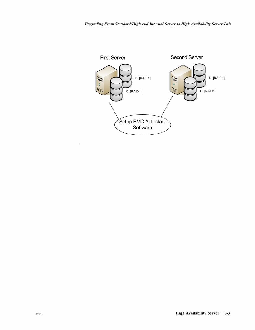
Upgrading From Standard/High-end Internal Server to High Availability Server Pair
8081318 High Availability Server 7-3
.
D: [RAID1]
First Server
C: [RAID1]
D: [RAID1]
Second Server
C: [RAID1]
Setup EMC AutostartSoftware
Installing EMC Autostart
7-4 High Availability Server 8081318
Installing EMC Autostart
New Setup and Upgrade from Existing Database
Prerequisites If upgrading from a previous OB TraceVue, store the office Backup files (OB TraceVue, and TV_Templates if applicable) from the internal server in a safe location and newly install the server to be upgraded. Two installed Windows Server 2003 based systems (two disks, two NICs available) are required.OB TraceVue must not be installed.The time difference between both server or servers and central time server must be below 24 hours.Firewall must be turned off on both servers.Cross wired LAN (mirroring) must be connected on both servers.1
OB TraceVue LAN must be connected on both servers.1
Separate partitions:C: Windows OS, swap file resides on C:D: empty NTFS partition, exactly the same size on both nodes.
Check the size of drive D: on both servers. If the size is not the same on each: Open disk management.
Delete drive D: partition.
On the server with the smaller D: capacity, create a new partition with the maximum available capacity. Note the number of Mbytes entered. Enter the following settings:
Primary partitionFile System: NTFSVolume Label: OBTVPerform a quick format
On the server with the larger D: capacity, create a new partition with the capacity you noted previously. Enter the following settings:
Primary partitionFile System: NTFSVolume Label: OBTVPerform a quick format
1. First NIC (OB TraceVue) is recognized by windows under Network Connections in the control panel as OBTV LAN Connection.The Second NIC (mirroring) is recognized by Windows under Network connections in the control panel as the default Local Area Connection - 2.

Installing EMC Autostart
8081318 High Availability Server 7-5
Preparation onEach Server
1. Perform and write down the network settings on the table EMC Autostart Installation Record on page 7-6. Store this record in the system binder.
2. You are recommended to provide friendly names (such as OBTV LAN for the first NIC and Mirroring LAN for the second NIC), for the network connections.
Right click My Network Places → Properties.Right click the connection and select Rename.
3. Set the network properties of both mirroring LAN interfaces
The mirroring LAN must only have TCP/IP enabled. Uncheck everything except TCP/IP. The HP Network config cannot be unchecked.
Select TCP/IP Properties; enter IP Address and Subnet mask
Click Advanced...At the DNS tab: disable Register this connection's addresses in DNSAt the WINS tab: disable Enable LMHOSTS lookup.
select Disable NetBIOS over TCP/IP
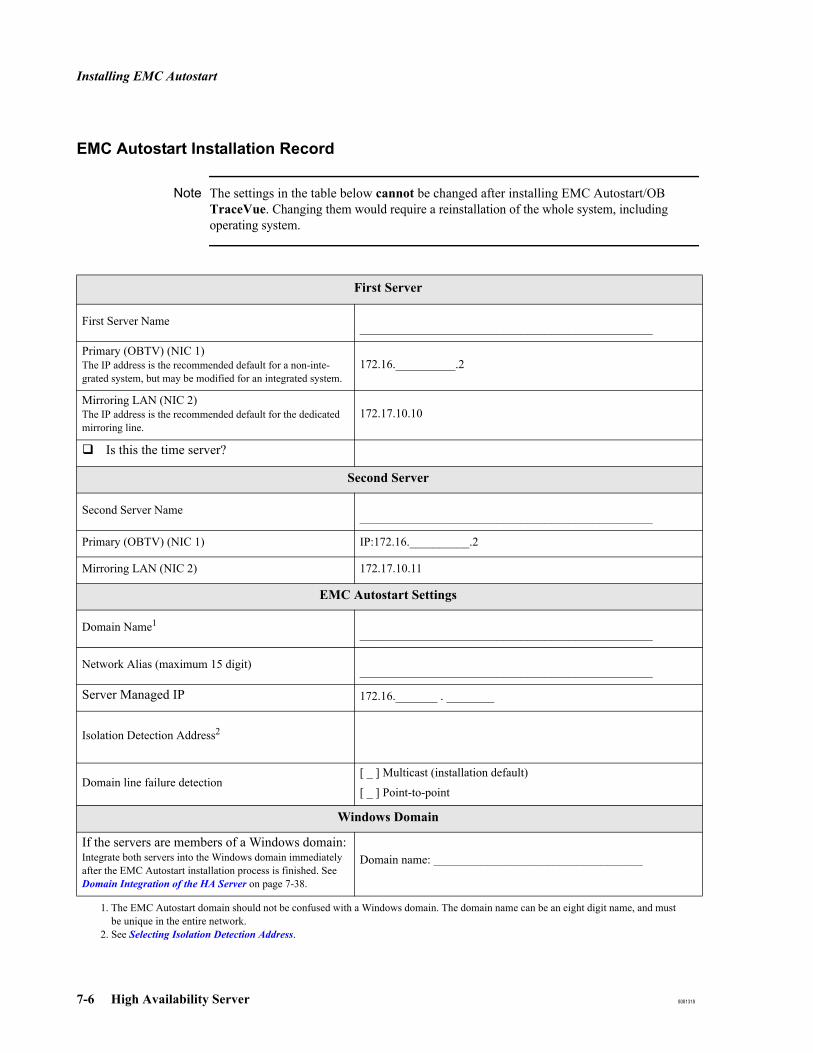
Installing EMC Autostart
7-6 High Availability Server 8081318
EMC Autostart Installation Record
Note The settings in the table below cannot be changed after installing EMC Autostart/OB TraceVue. Changing them would require a reinstallation of the whole system, including operating system.
First Server
First Server Name _________________________________________________
Primary (OBTV) (NIC 1)The IP address is the recommended default for a non-inte-grated system, but may be modified for an integrated system.
172.16.__________.2
Mirroring LAN (NIC 2)The IP address is the recommended default for the dedicated mirroring line.
172.17.10.10
Is this the time server?
Second Server
Second Server Name _________________________________________________
Primary (OBTV) (NIC 1) IP:172.16.__________.2
Mirroring LAN (NIC 2) 172.17.10.11
EMC Autostart Settings
Domain Name1_________________________________________________
Network Alias (maximum 15 digit) _________________________________________________
Server Managed IP 172.16._______ . ________
Isolation Detection Address2
Domain line failure detection[ _ ] Multicast (installation default)
[ _ ] Point-to-point
Windows Domain
If the servers are members of a Windows domain:Integrate both servers into the Windows domain immediately after the EMC Autostart installation process is finished. See Domain Integration of the HA Server on page 7-38.
Domain name: ___________________________________
1. The EMC Autostart domain should not be confused with a Windows domain. The domain name can be an eight digit name, and must be unique in the entire network.
2. See Selecting Isolation Detection Address.
Installing EMC Autostart
8081318 High Availability Server 7-7
Selecting IsolationDetection Address
Even though it is not required, it is highly recommended to implement isolation detection addresses.
EMC Autostart allows you to supply multiple addresses for isolation detection. The addresses are used to determine if the node is isolated from the network. Isolation detection determines if a network connection has been cut off. Its purpose is to protect a node from being unable to communicate with any other resource. The loss of communication is typically a result of network card failure or cable removal on the node.
Use static IP addresses for isolation detection. The IP addresses you provide can be other devices on the same network but they must also include a hardware router or a managed switch to ensure that isolation is detected only when the node is completely isolated from the network.
Rules
Choose hardware routers or managed switches as isolation detection addresses where traffic to both servers from the clients is combined. Remember to include all redundant paths on the same level.If no networking hardware with a static IP address is available, use one or more OB TraceVue PCs with static IP addresses and which are always operational. Use Web/Terminal Server and External Server. Do not use beside clients.
Note If none of the configured detection addresses can be reached from either of the two servers, the HA system becomes inoperable.For isolation detection, a ping signal is sent to the configured isolation detection addresses. If at least one ping is returned, no action is taken. Make sure your network setup allows “ping” to be sent from HA servers to the configured isolation detection addresses. For detailed network configuration of the isolation detection addresses please refer to the information on port numbers in the Integration Guide.
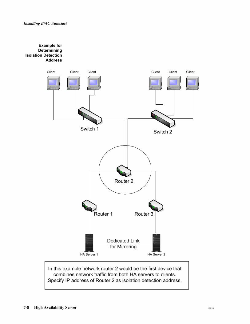
Installing EMC Autostart
7-8 High Availability Server 8081318
Example forDetermining
Isolation DetectionAddress
Client Client Client Client Client Client
Dedicated Linkfor Mirroring
In this example network router 2 would be the first device thatcombines network traffic from both HA servers to clients.
Specify IP address of Router 2 as isolation detection address.
UID
HP ProLiant ML350g5
HA Server 1
UID
HP ProLiant ML350g5
HA Server 2
Router 1 Router 3
Router 2
Switch 1 Switch 2
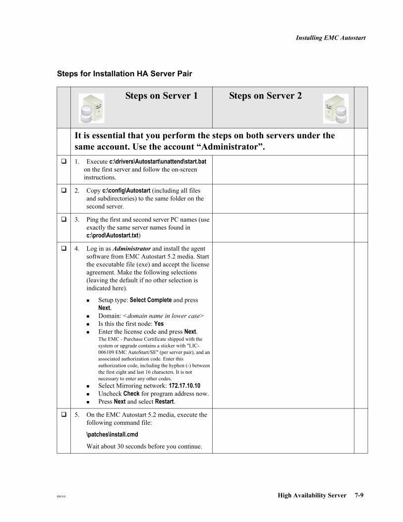
Installing EMC Autostart
8081318 High Availability Server 7-9
Steps for Installation HA Server Pair
Steps on Server 1 Steps on Server 2
It is essential that you perform the steps on both servers under the same account. Use the account “Administrator”.1. Execute c:\drivers\Autostart\unattend\start.bat
on the first server and follow the on-screen instructions.
2. Copy c:\config\Autostart (including all files and subdirectories) to the same folder on the second server.
3. Ping the first and second server PC names (use exactly the same server names found in c:\prod\Autostart.txt)
4. Log in as Administrator and install the agent software from EMC Autostart 5.2 media. Start the executable file (exe) and accept the license agreement. Make the following selections (leaving the default if no other selection is indicated here).
Setup type: Select Complete and press Next.Domain: <domain name in lower case>Is this the first node: YesEnter the license code and press Next.The EMC - Purchase Certificate shipped with the system or upgrade contains a sticker with "LIC-006109 EMC AutoStart/SE" (per server pair), and an associated authorization code. Enter this authorization code, including the hyphen (-) between the first eight and last 16 characters. It is not necessary to enter any other codes.Select Mirroring network: 172.17.10.10Uncheck Check for program address now.Press Next and select Restart.
5. On the EMC Autostart 5.2 media, execute the following command file:
\patches\install.cmd
Wait about 30 seconds before you continue.

Installing EMC Autostart
7-10 High Availability Server 8081318
6. If there is no dedicated timeserver in the network, configure this server as timeserver now by executing: C:\config\Autostart\MakeTimeServer.cmd.
If a dedicated timeserver exists in the network (for instance domain integration), setup the site-specific time synchronization AFTER completing the EMC Autostart installation process. See Windows Time Service on page 19-23.
If integrated into the domain, the domain controller is the time server and no further steps are necessary.
7. Execute the command file C:\config\Autostart\PrepSystem.cmd
8. Reboot.Login as AdministratorOpen the Management Console (Start → Programs → EMC Autostart Console) Wait until the node of the first server shows a green lightClose Management Console.
9. Add users. Execute: C:\config\Autostart\Users.cmd.
10. Stop services/set manual startup by executing C:\config\Autostart\Stopsrv.cmdProceed with Step a on the second server.
Steps on Server 1 Steps on Server 2
It is essential that you perform the steps on both servers under the same account. Use the account “Administrator”.
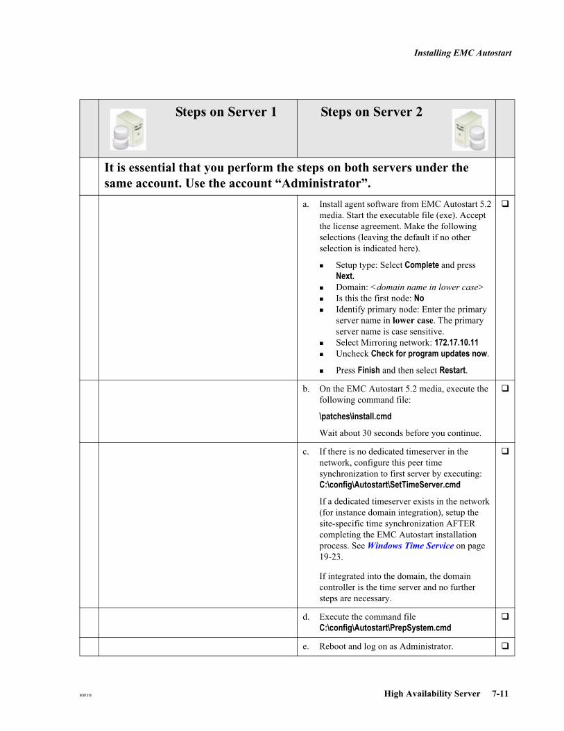
Installing EMC Autostart
8081318 High Availability Server 7-11
a. Install agent software from EMC Autostart 5.2 media. Start the executable file (exe). Accept the license agreement. Make the following selections (leaving the default if no other selection is indicated here).
Setup type: Select Complete and press Next.Domain: <domain name in lower case>Is this the first node: NoIdentify primary node: Enter the primary server name in lower case. The primary server name is case sensitive.Select Mirroring network: 172.17.10.11Uncheck Check for program updates now.
Press Finish and then select Restart.
b. On the EMC Autostart 5.2 media, execute the following command file:
\patches\install.cmd
Wait about 30 seconds before you continue.
c. If there is no dedicated timeserver in the network, configure this peer time synchronization to first server by executing: C:\config\Autostart\SetTimeServer.cmd
If a dedicated timeserver exists in the network (for instance domain integration), setup the site-specific time synchronization AFTER completing the EMC Autostart installation process. See Windows Time Service on page 19-23.
If integrated into the domain, the domain controller is the time server and no further steps are necessary.
d. Execute the command file C:\config\Autostart\PrepSystem.cmd
e. Reboot and log on as Administrator.
Steps on Server 1 Steps on Server 2
It is essential that you perform the steps on both servers under the same account. Use the account “Administrator”.

Installing EMC Autostart
7-12 High Availability Server 8081318
f. Open EMC autostart console. Under "Node" select 2nd server. Select Failure Detection and Mirroring. Under Remote Mirror Host, select "1st Server". Click Apply.
g. In the Management Console: Create Drive_D mirror.
Right-click Data Sources → Create New Data Source → EMC Mirroring for Windows. Data source name: Drive_D Source node: 2nd server nameTarget node: 1st Server nameClick ApplyClose the Management Console
h. Create the OBTVSetup Group (including alias, managed IP, Drive_D, registry mirror).
Execute C:\config\Autostart\OBTVPreparation.cmd
i. Stop services/set manual startup Execute C:\config\Autostart\StopSrv.cmd
j. Open the Management Console, right-click OBTVSetup in resource group and select bring online on the second server.
Wait until Drive D: mirror is synchronized (wait until the resynchronization window disappears). This operation takes approximately 45 minutes.
Steps on Server 1 Steps on Server 2
It is essential that you perform the steps on both servers under the same account. Use the account “Administrator”.

Installing EMC Autostart
8081318 High Availability Server 7-13
k. Install OB TraceVue from CD:select Install the OB TraceVue Software.if restoring from an existing backup, select Restore a previously saved TraceVue installation.select the HA option.activate General Settings → Storage.only if define storage settings is enabled:i. Select Define Storage settings.
ii. In the next screen (specify Archive and Retrieve settings), make sure that configure archiving and Retrieve running on this PC is not checked.
assign the managed IP address as the internal server IP address.disable auto-login, if it is not required.if using auto-login, change the user to the authenticated user defined in the EMC Autostart console for the OB TraceVue application (administrator).Caution: This means that a user with full OB TraceVue administrator privileges is permanently logged into the system.
These steps include an automatic reboot (initiating automatic relocation of OBTVSetup group to the first node/server). The Drive_D mirror status on Server 1 will turn yellow, and then green again, after the reboot of Server 2 is complete.
Proceed with Step 11 on the first server.
11. Open Management Console: Navigate to Resource Groups/OBTVSetup. Check if the group state in the right window pane says "online" and node is server 1.
Steps on Server 1 Steps on Server 2
It is essential that you perform the steps on both servers under the same account. Use the account “Administrator”.

Installing EMC Autostart
7-14 High Availability Server 8081318
12. If restoring a backup, including templates:
remove directory d:\tv2_templates
run Backup Tool from CD to restore tv2_templates directory and select D:\ as the location from which to restore the offline backup.
13. Install OB TraceVue from CD: (select install and do not change system settings). A system reboot is included automatically in this.
Disable auto-login, if it is not required.
If using auto-login, change the user to the authenticated user defined in the EMC Autostart console for the OB TraceVue application (administrator).
Caution: This means that a user with full OB TraceVue administrator privileges is permanently logged into the system
14. Log on as Administrator. Open Management Console: Take OBTVSetup resources offline (right click Resource Groups\ OBTVSetup → take offline)
Wait until status is offline (grey status icon).
15. Add EMC Autostart OB TraceVue information Execute: C:\config\Autostart\OBTVCfg.cmd)
16. Management Console: Stop monitoring for Group OBTVSetup and for OBTVTools(right click the resource group and select Stop Monitoring)
Steps on Server 1 Steps on Server 2
It is essential that you perform the steps on both servers under the same account. Use the account “Administrator”.
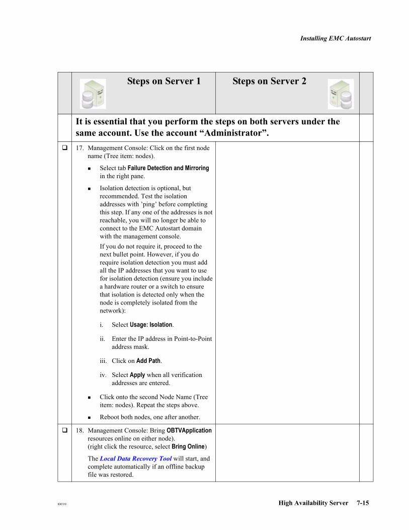
Installing EMC Autostart
8081318 High Availability Server 7-15
17. Management Console: Click on the first node name (Tree item: nodes).
Select tab Failure Detection and Mirroring in the right pane.
Isolation detection is optional, but recommended. Test the isolation addresses with ’ping’ before completing this step. If any one of the addresses is not reachable, you will no longer be able to connect to the EMC Autostart domain with the management console.If you do not require it, proceed to the next bullet point. However, if you do require isolation detection you must add all the IP addresses that you want to use for isolation detection (ensure you include a hardware router or a switch to ensure that isolation is detected only when the node is completely isolated from the network):
i. Select Usage: Isolation.
ii. Enter the IP address in Point-to-Point address mask.
iii. Click on Add Path.
iv. Select Apply when all verification addresses are entered.
Click onto the second Node Name (Tree item: nodes). Repeat the steps above.
Reboot both nodes, one after another.
18. Management Console: Bring OBTVApplication resources online on either node).(right click the resource, select Bring Online)
The Local Data Recovery Tool will start, and complete automatically if an offline backup file was restored.
Steps on Server 1 Steps on Server 2
It is essential that you perform the steps on both servers under the same account. Use the account “Administrator”.

Installing EMC Autostart
7-16 High Availability Server 8081318
19. Start OB TraceVue on any client. For a new installation, OB TraceVue must be installed on the client to perform this step. The Local Data Recovery Tool will start automatically if an offline backup file was restored and the external server is started.
In the Management Console:
Click on EMC Autostart domain name in the left pane, and click the Licensing/Security tab in the right pane.
Make sure that the domain name is visible in the "Product" pulldown list, and verify the following:
License Type: Site.Expires: Permanent License.
20. Test the installation, as described in Installation Test on page 7-25..
If the servers are part of a domain, integrate both servers into the Windows domain. See Domain Integra-tion of the HA Server in Chapter 7, on page 38.If multicast network communication between the first NIC of both servers is not 100% reliable (for example, if in the Legato console periodically changes occur in repeated cycles - that is the Node status (turns red) and associated NIC (turns yellow), for approximately 30 seconds and then returns to green, you can consider switching to "point-to-point" communication. Follow the process Switching Node Failure Detection to Point-to-point.
Steps on Server 1 Steps on Server 2
It is essential that you perform the steps on both servers under the same account. Use the account “Administrator”.
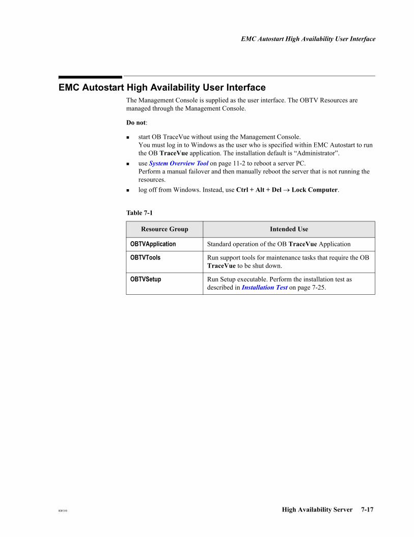
EMC Autostart High Availability User Interface
8081318 High Availability Server 7-17
EMC Autostart High Availability User InterfaceThe Management Console is supplied as the user interface. The OBTV Resources are managed through the Management Console.
Do not:
start OB TraceVue without using the Management Console.You must log in to Windows as the user who is specified within EMC Autostart to run the OB TraceVue application. The installation default is “Administrator”.use System Overview Tool on page 11-2 to reboot a server PC.Perform a manual failover and then manually reboot the server that is not running the resources.log off from Windows. Instead, use Ctrl + Alt + Del → Lock Computer.
Table 7-1
Resource Group Intended Use
OBTVApplication Standard operation of the OB TraceVue Application
OBTVTools Run support tools for maintenance tasks that require the OB TraceVue to be shut down.
OBTVSetup Run Setup executable. Perform the installation test as described in Installation Test on page 7-25.

EMC Autostart High Availability User Interface
7-18 High Availability Server 8081318
Taking ResourceGroups Online /
Offline
Have only one resource group online at a time. A green bullet in front of the resource group name indicates when this group is online. When you take one resource group offline, and bring another online wait until the bullet in front of the group you are taking offline turns gray. Only then continue with bringing the other resource group online.
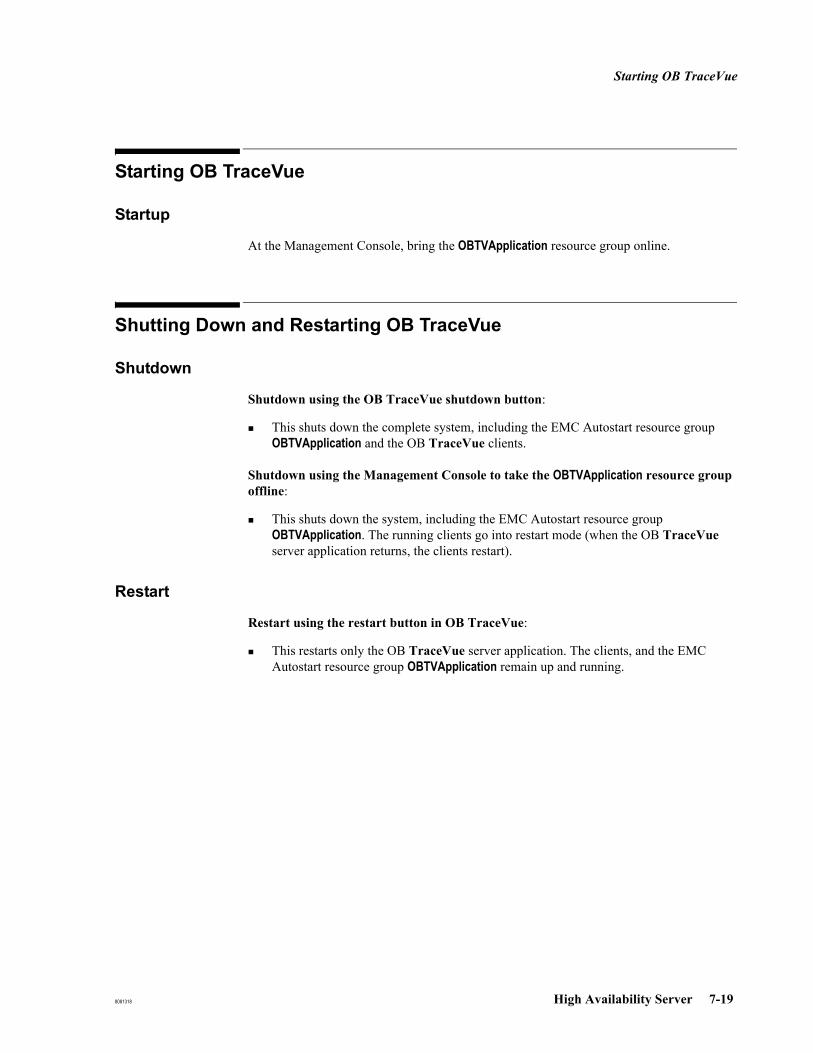
Starting OB TraceVue
8081318 High Availability Server 7-19
Starting OB TraceVue
Startup
At the Management Console, bring the OBTVApplication resource group online.
Shutting Down and Restarting OB TraceVue
Shutdown
Shutdown using the OB TraceVue shutdown button:
This shuts down the complete system, including the EMC Autostart resource group OBTVApplication and the OB TraceVue clients.
Shutdown using the Management Console to take the OBTVApplication resource group offline:
This shuts down the system, including the EMC Autostart resource group OBTVApplication. The running clients go into restart mode (when the OB TraceVue server application returns, the clients restart).
Restart
Restart using the restart button in OB TraceVue:
This restarts only the OB TraceVue server application. The clients, and the EMC Autostart resource group OBTVApplication remain up and running.
OB TraceVue SW-upgrade at HA-pair
7-20 High Availability Server 8081318
OB TraceVue SW-upgrade at HA-pair
Preparing for Upgrading
1. Take the OBTVApplication resource group offline.
2. Make an offline backup and store it in a safe location.
OS/EMC Upgrade
When upgrading from OB TraceVue E.00.00, E.00.10, or E.00.20 (not E.00.21 and higher):
Rename the network connection heartbeat to mirroring (see Preparation on Each Server on page 7-5)perform step 17 on page 7-15 (isolation detection)perform step 20 on page 7-16 (initiate an automatic failover).
If you are upgrading from E.xx.xx (including E.00.21 and higher) perform these steps.
1. In Legato console check for all green indicators before starting the upgrade, and correct as necessary.
2. Determine what Server was the last active node by selecting OBTV Application Resource Group and checking right pane for node name.
3. If not already done, as instructed in Upgrading the Operating System on page 21-6, Start upgrade\upgrade.cmd from OB TraceVue server CD-ROM on both nodes.

OB TraceVue SW-upgrade at HA-pair
8081318 High Availability Server 7-21
4. Upgrade Legato CSBSAA 5.1 to EMC Autostart 5.2:
a. Open the management console.
b. Take all resource groups offline.
c. Close the management console.
d. Use add/remove programs to uninstall the console on both nodes. Do not uninstall CSBSAA Agent. Restart both nodes and login as Administrator.
e. Upgrade the first node:
i. Insert the EMC Autostart 5.2 CD.
ii. Upgrade by executing the command \EAS52SP3.WIN.exe from the EMC Autostart CD media.
iii. Select to install the "complete" program.
iv. Continue the wizard screens with default selections, acknowledging any message to stop services.
v. Uncheck the option to check for updates now.
vi. Select NOT to reboot when the installation is finished.
vii. On the EMC Autostart 5.2 media, execute the following command file: \patches\install.cmd
viii. Wait about 30 seconds, then reboot the PC.
f. Upgrade the second node by repeating steps i-viii.
g. After the upgrade to EMC Autostart 5.2, leave the license key as it is. Keep the new license key in case it is required for a complete reinstallation.
h. Highlight the node aliases. In the properties page, uncheck Register with an enabled workstation service (required WINS server) and select Apply.
OB TraceVue Upgrade
1. Bring the resource group OBTV Setup online. (For an EMC upgrade, make sure you bring this online on the server whose name you noted.)
2. Run the OB TraceVue Setup from CD. Select:Install the OB TraceVue softwareKeep existing database and data files
3. Re-locate the OBTVSetup resource group to the other node.
4. Repeat Step 2.5. Take the OBTVSetup resource group offline.
6. Bring the OBTVApplication resource group online.

OB TraceVue SW-upgrade at HA-pair
7-22 High Availability Server 8081318
Testing the HA System
1. Perform the installation test as described in Installation Test on page 7-25.
Maintenance
8081318 High Availability Server 7-23
Maintenance
Performing a Manual Failover
1. In the Management Console right-click the resource group OBTVApplication.
2. Select Relocate Resource Group
3. Select the passive node.
Monitoring the Domain Daily
1. Open the console at least once a day.
2. Check the status of all resource items, all must be green.
If not all resource items are green, locate and repair the failed item.
Maintenance on the Passive Server
To perform maintenance on the operating system and avoid performance drawbacks for the active server, the EMC Autostart services must be stopped.
1. In the Management Console right-click the passive node.
2. Select Shutdown Agent.
3. Stop all EMC Autostart services still running (Mirror, Backbone, Cluster Transport)
4. Perform the maintenance tasks on the now isolated server
5. Reboot the server. In the Management Console the data source and node status should go back to the state OK.
Switching Node Failure Detection to Point-to-point
Installation default is node failure detection based on domain line multicast communication. This process switches to point-to-point communication.
1. Take resource group offline, wait until offline (gray icon).
2. Repeat these steps for both nodes:
Select one node on left pane.
Select "Failure detection and mirroring" tab on right pane.
Select (highlight) "Domain" path under "Network usage".
Change selection from "Multicast" to "point-to-point".
Enter the IP Address of the other server primary IP as the destination address in the fields that now become visible.

Maintenance
7-24 High Availability Server 8081318
Select "Edit path" and press "Apply" to apply changes.
Leave "Verification Path" as is.
Creating an Offline Backup
1. Take resource group OBTVApplication offline.
2. Bring resource group OBTVTools online.
The status of the messaging service will turn red temporarily while the tool is running. It will turn green again once the OBTVTools resource group has been taken offline and the OBTVApplication resource group has been brought online again.
3. Perform an offline back up of OB TraceVue using the Backup Tool and the template files (if applicable).
Restoring a TV Backup
1. Take resource group OBTVApplication offline.
2. Bring resource group OBTVSetup online on any of the two nodes.
3. Uninstall OB TraceVue (automatic reboot).It is not required to also run setup on the other node to uninstall OB TraceVue. The replication takes care of it.
4. Log in as Windows administrator.
5. Bring resource group OBTVSetup offline.
6. Bring resource group OBTVSetup online on any of the nodes.
7. Delete \TV2 directory from D: (and \TV2_Templates if applicable).
8. Run the Backup Tool from CD. Select D:\ as the location to restore the offline backup.
9. Run OB TraceVue Setup from CD: Select Install the OB TraceVue software Select Keep existing database and data files. Select the HA option.Activate General Settings -> Storage.Only if Define Storage settings is enabled:
Select Define Storage settingsIn the next screen (specify Archive and Retrieve settings) make sure that Configure Archiving and Retrieve running on this PC is not checked.
Assign the managed IP Address as the Internal Server IP.Disable auto-login, if it is not required.If using auto-login, change the user to the authenticated user defined in the EMC Autostart console for the OB TraceVue application (administrator).
Caution: This means that a user with full OB TraceVue administrator privileges is permanently logged into the system.
Maintenance
8081318 High Availability Server 7-25
10. Relocate the resource group OBTVSetup to other node.
11. Repeat Step 9 for that node.
12. Take resource group OBTVSetup offline.
13. Bring resource group OBTVApplication online and perform an installation test as described in Installation Test on page 7-25.
Installation Test
Execute this test after the Setup program has been used to either install software or change system settings on a High Availability system. Make sure that OBTV Application resource group is online and OB TraceVue is running on at least one client.
1. Create a quick admit patient in any bed, and note the generated patient name here:
Quick admit test patient name _______________________________________
2. Isolation detection:
If isolation detection is configured, unplug the OB TraceVue network cable at the online server.
If isolation detection is not configured, shut down Windows 2003 on the online server.
3. Make sure the following verification succeeds. Check each item off in the [ ] box:
[ ] OB TraceVue comes up on the other server. If the network cable has been unplugged, plug it back in and check if the node comes up in the Management Console again.
[ ] OB TraceVue restarts automatically on the client computer.
[ ] The noted quick admit test patient is available in OB TraceVue.
[ ] Clean up the database by deleting the quick admit test patient.
(Select "Identify/Search Patient" , and press Delete Patient.)
Changing the System Time
The system time must only be changed at the time server:
If one of the OB TraceVue High Availability Servers is the time server (check EMC Autostart Installation Record on page 7-6) then the time must be changed on that server.If an outside time server provides the time, the time must be corrected on that server.

EMC Autostart Server Recovery
7-26 High Availability Server 8081318
EMC Autostart Server RecoveryTo recover a failed high availability system, follow the procedure shown in the flowchart. The numbered boxes correspond with the numbered processes that follow the flowchart.
HA RecoveryDone
StartHA Recovery
(1) Open EMC Autostart console.Check OBTV Application resource group,
nodes & NICs
All green?
(2) Locate the failed component and repair it.
All green?
(5) Reinstall the failed server,Rejoin the EMC Autostart Domain according to procedure “Synchronizing a Re-Installed
Server”
All green?
TVBackupavailable ?
(6) New install theHA servers acc. to
upgrade procedure;which makes use ofTVBackup to restore
existing DB
(7) New install the HAservers.
Perform RFAprocess.
(3) Reboot both nodes.
All green?
No
No
Yes
Yes
Yes
No
Yes
Yes
No
(8) Performinstallation test
No
Yes
No
(4) Restart themirror.
All green?Yes
No
Data sourceyellow for more than
15 minutes?
EMC Autostart Server Recovery
8081318 High Availability Server 7-27
1. Open the EMC Autostart Management Console
1. Launch the Management Console on the active server:Start → Programs → EMC Autostart Console
2. Check the status of all resource items in Resource Group OBTVApplicationNodesNICs
If all items in the EMC Autostart Domain are green the HA software is ready for another failover.
2. Locating and Repairing the Failed Component
1. Open the Management Console on the active server.
2. Locate the failed component.
3. Determine the failure type:
a. If it is a software failure, follow OB TraceVue Repair on page 17-1. Remember:OB TraceVue Tools requires resource group OBTVTools to be onlineOB TraceVue Setup requires resource group OBTVSetup to be onlineAfter executing setup, run the Installation Test on page 7-25.
b. If it is a Hardware failure:
i. If the failed component is part of the active server, perform a manual failover.ii. Shutdown the standby server and replace the failed component. If you repair a
failed NIC or mainboard (with onboard NIC) follow How to Replace a NIC Card on page 7-27.
iii. Reboot the repaired standby server.
How to Replace aNIC Card
1. Replace the NIC (or mainboard if onboard NIC is defective).
2. Reboot the PC.
3. Set the previous IP Address (as noted on the EMC Autostart Installation Record on page 7-6) on the NIC.
4. Select No in warning message.
5. Reboot the PC.
3. Rebooting Both Nodes
1. Reboot one of the nodes. Open the Management Console on the other node.
2. Wait until the status of the rebooted node is green.
3. Wait until the resource group OBTVApplication has green (or gray) status.
4. Reboot the other node.

EMC Autostart Server Recovery
7-28 High Availability Server 8081318
4. Restart the Mirror
Note Do not continue with this procedure if the Data Source Drive_D is in yellow state and shows the caption Sync Complete xx%. Wait until the synchronization has finished. During the synchronization, the system performance may be decreased.
DeterminingCurrent Data Node
To determine which node contains the current data in case the Data Source Drive_D is in yellow or red state perform the following:
Manually resynching nodes, active node is known.
If the Data Source is in a yellow or red state but OB TraceVue is running on a node and serving clients, this node is more likely to have the most current patient data. It is strongly recommended that the customer validates the status of patient data before resynching the nodes.
1. On the active node, create an online backup of the OB TraceVue installation and the template files (if applicable) and store them in a safe location (not on the D: drive !).
2. In the Autostart console, right-click the data source Drive_D.
3. Select Restart Mirror, select Yes to continue. While the Drive_D mirror is synchronizing it is in yellow state and shows the caption Sync Complete xx%.
4. Wait until synchronization has finished (Drive_D is in green state).
Caution: Once you have initiated this procedure, avoid any activities for the next hour that might bring the data source down (for example, do not shut down OB TraceVue or the server).
If it is not possible to resynch the servers manually, continue with EMC Autostart Server Recovery step 5 whereas the inactive node needs re-installation.
Manually resynching nodes, active node is not known
If the Data Source is in yellow or red state but OB TraceVue is not running on any node and it is not clear which node has the up-to-date patient data, use the following procedure:
1. Completely shut down one of the nodes. This will be node B.
2. On node A bring the OBTVtools RG online and create an offline backup of the OB TraceVue installation and the template files (if applicable) and store them in a safe location (not on the D: drive !).
3. Take the OBTVtools RG offline and bring the OBTVApplication RG online.
4. Check with the customer the actuality of the patient data.
5. Stop OB TraceVue and completely shut down node A.
6. Boot up node B, bring the OBTVtools RG online and create an offline backup of the

EMC Autostart Server Recovery
8081318 High Availability Server 7-29
OB TraceVue installation and the template files (if applicable) and store them in a safe location (not on the D: drive !).
7. Take the OBTVtools RG offline and bring OBTVApplication RG online.
8. Check with the customer the actuality of the patient data.
9. Completely shut down the node that has the older data.
10. If applicable, boot the node that has the most current data and bring the OBTVApplication RG online (this will be the data source during synch).
11. Boot the other node and log on to Windows (this will be the data destination during synch).
12. In the Autostart console, right-click the data source Drive_D.
13. Select Restart Mirror, select Yes to continue. While the Drive_D mirror is synchronizing it is in yellow state and shows the caption Sync Complete xx%.
14. Wait until synchronization has finished (Drive_D is in green state).
Caution: Once you have initiated this procedure, avoid any activities for the next hour that might bring the data source down.
If it is not possible to resynch the servers manually, continue with EMC Autostart Server Recovery step 5 whereas the node with the older data needs re-installation.
5. Synchronizing a Re-Installed Server
When a single server in the domain needs to be reinstalled (recovered server) while the other is online (surviving server), it must be reinstalled and rejoined into the EMC Autostart Domain using the following procedure.
Retrieve the EMC Autostart Installation Record from System Binder as written down in EMC Autostart Installation Record on page 7-6. Reapply the IP Address and PC Name.
Caution: Create a backup of the surviving server and store it in a safe location.
Prerequisites OB TraceVue must not be installed on the recovered server.The time difference between both server or servers and central time server must be below 24 hours.Firewall must be turned off on both servers.Cross wired LAN (mirroring) must be connected on both servers.OB TraceVue LAN must be connected on both servers.Separate partitions:
C: Windows OS, swap file resides on C:

EMC Autostart Server Recovery
7-30 High Availability Server 8081318
D: empty NTFS partition, exactly the same size on both nodes.
i. See the partition size on the surviving server. At the Management Console, select Data Sources -> Drive D in the left pane. Then select settings in the right pane.
ii. Format D:\
Do not select quick format.

EMC Autostart Server Recovery
8081318 High Availability Server 7-31
Preparation All of the following steps are performed on the recovered server.
1. You are recommended to provide friendly names (such as OBTV for the first NIC and Mirroring for the second NIC), for the network connections.
Right click My Network Places → Properties.Right click the connection and select Rename.
2. Set the network properties of the mirroring LAN interface
The mirroring LAN must only have TCP/IP enabled. Uncheck everything except TCP/IP. The HP Network config cannot be unchecked.
Select TCP/IP Properties; enter IP Address and Subnet maskClick Advanced...At the DNS tab: disable Register this connection's addresses in DNSAt the WINS tab: disable Enable LMHOSTS lookup.
select Disable NetBIOS over TCP/IP
3. Copy the entire directory c:\config\Autostart (including all files and subdirectories) of the surviving server to the same folder on the recovered server.
4. Install agent software from EMC Autostart 5.2 CD and start the executable file (exe). Accept the license agreement. Make the following selections (leaving the default if no other selection is indicated here):
Select Complete and click Next..Domain: <enter domain name in lower case>.Is this the first node: No, there is an existing node...Identify primary node: <enter name of surviving server in lower case>.Select Mirroring network: <select IP of NIC connected to mirroring LAN>.Uncheck Check for program updates now.
Press Finish.
Restart and login as Administrator..
5. On the EMC Autostart 5.2 media, execute the following command file: \patches\install.cmd.
Wait about 30 seconds before you continue.
6. Re-establish time synchronization between both servers:
If the customer has a dedicated timeserver (for instance domain integration), then setup site-specific time synchronization.
If the customer has no time server in the network and:the recovered server was the first server previously, then executeC:\config\Autostart\MakeTimeServer.cmd.the recovered server was the second server previously, then executeC:\config\Autostart\SetTimeServer.cmd.
7. If your HA system is configured to use point-to-point communication for node failure

EMC Autostart Server Recovery
7-32 High Availability Server 8081318
detection, perform the following:
a. Select the recovered node in the left pane.
b. Select the Failure detection and mirroring tab in the right pane.
c. Select (by highlighting) Domain path under Network usage.
d. Change the selection from Multicast to point-to-point.
e. Enter the IP Address of the other server’s primary IP as the destination address in the fields that are now visible.
f. Select Edit path and press Apply to apply the changes.
g. Leave the Verification Path as is.
8. Execute the batch file PrepSystem.cmd.
9. Reboot the recovered server.
10. Login as Administrator.
11. Start the Management Console and take OBTVApplication offline. Make sure you inform the users about the downtime before you take OB TraceVue down.
12. If isolation detection was configured, check the isolation detection destination IP address.
RestartingSynchronization of
the Drive_D
1. At the Management Console: restart mirroring of Drive_D:
a. Delete Drive_D from the resource groups OBTVApplication, OBTVSetup, and OBTVTools. For each resource group:
Select the resource group in left pane.Select Settings tab in the right pane.For both startup and shutdown sequence select Drive_D, click Delete.Apply changes.
b. Delete the Drive_D mirror:
Select Data Sources → Drive_D in the left pane.Right-click and delete the data source.
c. Reboot both nodes (one after another). It does not matter in which order. Do not reboot the second node until Windows is running on the first node (ie, when the agent has turned green at the Management Console). After reboot, login as Administrator.
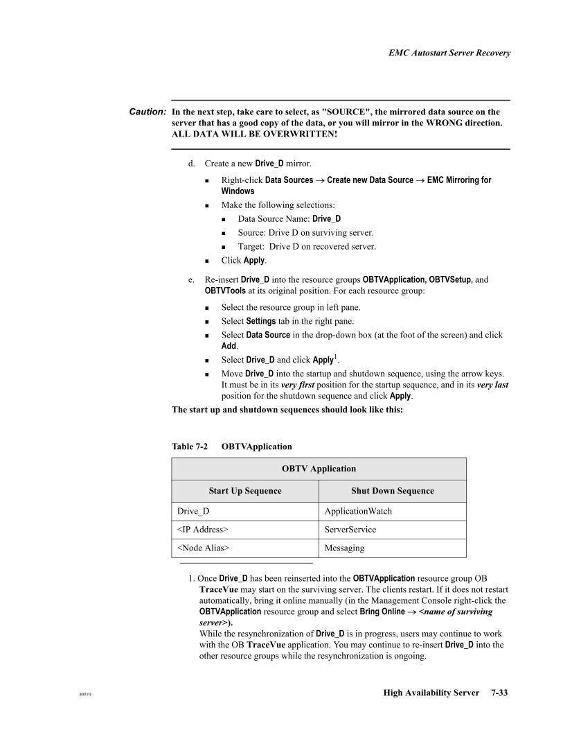
EMC Autostart Server Recovery
8081318 High Availability Server 7-33
Caution: In the next step, take care to select, as "SOURCE", the mirrored data source on the server that has a good copy of the data, or you will mirror in the WRONG direction. ALL DATA WILL BE OVERWRITTEN!
d. Create a new Drive_D mirror.
Right-click Data Sources → Create new Data Source → EMC Mirroring for WindowsMake the following selections:
Data Source Name: Drive_DSource: Drive D on surviving server.Target: Drive D on recovered server.
Click Apply.
e. Re-insert Drive_D into the resource groups OBTVApplication, OBTVSetup, and OBTVTools at its original position. For each resource group:
Select the resource group in left pane.Select Settings tab in the right pane.Select Data Source in the drop-down box (at the foot of the screen) and click Add. Select Drive_D and click Apply1. Move Drive_D into the startup and shutdown sequence, using the arrow keys. It must be in its very first position for the startup sequence, and in its very last position for the shutdown sequence and click Apply.
The start up and shutdown sequences should look like this:
1. Once Drive_D has been reinserted into the OBTVApplication resource group OB TraceVue may start on the surviving server. The clients restart. If it does not restart automatically, bring it online manually (in the Management Console right-click the OBTVApplication resource group and select Bring Online → <name of surviving server>).While the resynchronization of Drive_D is in progress, users may continue to work with the OB TraceVue application. You may continue to re-insert Drive_D into the other resource groups while the resynchronization is ongoing.
Table 7-2 OBTVApplication
OBTV Application
Start Up Sequence Shut Down Sequence
Drive_D ApplicationWatch
<IP Address> ServerService
<Node Alias> Messaging
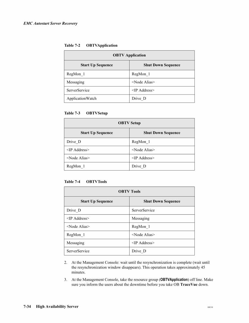
EMC Autostart Server Recovery
7-34 High Availability Server 8081318
2. At the Management Console: wait until the resynchronization is complete (wait until the resynchronization window disappears). This operation takes approximately 45 minutes.
3. At the Management Console, take the resource group (OBTVApplication) off line. Make sure you inform the users about the downtime before you take OB TraceVue down.
RegMon_1 RegMon_1
Messaging <Node Alias>
ServerService <IP Address>
ApplicationWatch Drive_D
Table 7-3 OBTVSetup
OBTV Setup
Start Up Sequence Shut Down Sequence
Drive_D RegMon_1
<IP Address> <Node Alias>
<Node Alias> <IP Address>
RegMon_1 Drive_D
Table 7-4 OBTVTools
OBTV Tools
Start Up Sequence Shut Down Sequence
Drive_D ServerService
<IP Address> Messaging
<Node Alias> RegMon_1
RegMon_1 <Node Alias>
Messaging <IP Address>
ServerService Drive_D
Table 7-2 OBTVApplication
OBTV Application
Start Up Sequence Shut Down Sequence
EMC Autostart Server Recovery
8081318 High Availability Server 7-35
4. Stop services/set manual: Execute C:\config\Autostart\StopSrv.cmd on the recovered server.
5. Management Console: Bring OBTVSetup resources online on the recovered server.
6. Install OB TraceVue from CD: (select the HA option, install software, keep settings and database. This includes a reboot).
7. Management Console: Take OBTVSetup resources offline.
8. Wait until status is offline (grey status icon).
9. Management Console: Bring OBTVApplication resources online.
6. New Installation of the HA Servers, OB TraceVue Backup Exists
1. Make sure the OB TraceVue Backup is stored in a safe location outside the HA Servers (for instance on a network share).
2. Reinstall both HA servers using the Windows 2003 installation process.
3. Reinstall the EMC Autostart Software according to Installing EMC Autostart on page 7-4.
7. New Installation of the HA Servers that Requires RFA
1. Reinstall both HA servers using the Windows 2003 installation process.
2. Reinstall the EMC Autostart Software according to Installing EMC Autostart on page 7-4.
3. Bring resource group OBTVTools online.
4. Start the RFA process at the external server according to Retrieve from Archive (RFA Wizard) on page 17-29.
5. After RFA is done, take resource group OBTVTools offline.
6. Bring resource group OBTVApplication online.
8. Performing an Installation Test
After the recovery of the HA system is done, perform an installation test as described in Installation Test on page 7-25.

Changing the Default OB TraceVue User at an HA System
7-36 High Availability Server 8081318
Changing the Default OB TraceVue User at an HA SystemThe default OB TraceVue user on a HA system is the Windows "Administrator". The following procedure let's you change it to another default user, which is not a Windows domain user.
1. Make sure you are logged on to Windows as the current default user "Administrator".
2. Make sure that no Resource group is online.
3. In Windows create a new user with a desired name, credentials and add it to the local user group "OBTV users". Perform this step equally on both nodes.
4. Register the new Windows user in the Management Console:
a. Start the Management Console as local administrator.
b. Select Domains -> [EMC Autostart Domain Name].
c. Select Tab "Licensing/Security".
d. Enter the user name, name of the first node, and access rights of "Operator".
e. Press Add.
f. Repeat step d. and e. with the second node name.
5. Set the new Windows user as the OB TraceVue application user.
a. Select Domains -> [EMC Autostart Domain Name] -> Processes -> Application Watch -> Default.
b. Make the following selection on the settings tab:
i. Domain: Do not erase the "." entered in this field. It determines that the new default user will be a local user and not a Windows domain user.
ii. Username: Enter the name of the new Windows user
iii. Password/Confirmation: Enter the appropriate password.
c. Apply the changes.
6. Step 6 is optional if a customer also would like to change the credentials of the

Changing the Default OB TraceVue User at an HA System
8081318 High Availability Server 7-37
Administrator account or rename it:
a. Select Domains -> [EMC Autostart Domain Name] -> Processes -> RegMon_1 -> Default.
b. Make the following selection on the settings tab:
i. Domain: Do not erase the "." entered in this field. It determines that the new default user will be a local user and not a Windows domain user.
ii. Username: Enter the name of the desired Windows user and make sure this user is member of the Windows user group "Administrators".
iii. Password/Confirmation: Enter the appropriate password.
c. Apply the changes.
7. Close the console.
8. Restart both servers, one after another and log on in Windows as the new default user.
9. Upon first start of the Management Console as the new Windows user, enter the name of the EMC Autostart domain in the "New Domain" window and click apply. This must be done on both servers.
10. Bring the OB TraceVue application online on the first server.
11. When the OB TraceVue login screen appears, perform a manual failover to the other server.
Changing Only Administrator Default Password
If a customer wants to change only the default password of the Administrator account, perform the following steps, which relate to the detailed steps given above. Make sure you have applied the same new password in Windows for the Administrator account on both nodes.
1.
2.
5. b. iii
5 c
6. b. iii
6 c
10.
11.

Domain Integration of the HA Server
7-38 High Availability Server 8081318
Domain Integration of the HA ServerTo enable the active directory integration, perform the following steps on a HA system that is installed, with the OB TraceVue application working on both nodes.
1. Take the resource groups offline (shut down OB TraceVue)
2. Integrate both servers of the HA system into the Windows domain.
a. Integrate the first server into the Windows domain.
b. Reboot the first server.
c. Integrate the second server into the Windows Domain.
d. Open the Management Console, and make sure that the first server agent is online again (green node).
e. Reboot the second server.
3. Register the HA server alias and the virtual IP in the DNS server.
4. Register the Windows domain user in the Management Console.
a. Start the Management Console on the HA server as local administrator.
b. Select Domains → [EMC Autostart Domain Name].
c. Select Tab "Licensing/Security".
d. Enter the user name, Windows domain name, and access rights of "Operator".
e. Press Add.
5. Set the Windows domain user as the OB TraceVue application user.
a. Start the Management Console.
b. Select Domains → [EMC Autostart Domain Name] → Processes → Application Watch → Default.
c. Make the following selection on the settings tab:
Domain: Enter the user domain name (Environment variable USERDOMAIN)..Username: Windows domain username that should be used as logon user for OB TraceVue (user requires group membership of local group "OBTV users" and of local group "Administrators" on both HA servers).Password/Confirmation: Enter the appropriate password.
d. Save the changes.
e. Close the console.
f. Restart both servers, one after another.
6. Bring the OB TraceVue application online on the first server.

Domain Integration of the HA Server
8081318 High Availability Server 7-39
7. Upon first start of the Management Console as domain user, enter the name of the EMC Autostart domain in the “New Domain” window and click apply. This must be done on both servers.
8. When the OB TraceVue login screen appears, perform a manual failover to the other server.
Health Status Icon Display
Occasionally, the EMC Autostart health status display icon may not be reliably refreshed. For example, when an unplugged network LAN is reconnected, the display may continue to show "failed". In such an instance, you can force a manual refresh by closing and restarting the complete system, including the OB TraceVue application. See Rebooting Both Nodes on page 7-27.

Domain Integration of the HA Server
7-40 High Availability Server 8081318

8081318 Network Based Storage 8-1
8Network Based Storage
IntroductionNetwork based storage (NBS) cannot be mixed with optical disk storage. Newly written archive files cannot be migrated to optical disks (including system merge). However, migration of existing data on optical media to the network storage is supported.
Network storage uses a directory path which is accessible by the PC on which these processes are running. This directory is accessible using the UNC (Universal Naming Convention) path or a local directory.
Prerequisites NBS requires sufficient free space for OB TraceVue to write the necessary data, which must be available for subsequent retrieval. If there is insufficient space, archiving of data is postponed until enough space is available. This may lead to filling up hard disk of internal server. Minimum initial space required is 50GB, plus the capacity of existing MO media.
Minimum access performance is 3MBytes/sec for read and write operation.
One storage location folder per system is needed. One location (directory) cannot be shared between multiple OB TraceVue systems.
The data on the network storage location must be secure from loss and corruption. OB TraceVue does not provide additional backup functionality. Any necessary additional backup must be provided by the hospital’s IT infrastructure.
Access Security The storage location must be secure from unauthorized access to ensure patient data confidentiality.
There are two possible models for the network location’s access security:
1. Implicit access using the interactive, and OBTV Internal user, access rights.
OB TraceVue and its tools access the network storage location using the credentials of the interactive logged in user and those of the 'OBTV Internal' windows user account.
To select this access model, do not enter user credentials in storage configuration page when running OB TraceVue setup.
When a local directory is used as a storage location or when a network device is used, it is necessary for the interactive logged-in user and the 'OBTV Internal' user account to have full control to the network storage location.
2. Explicit access by configuring a user/password in OB TraceVue
OB TraceVue setup provides the ability to configure a user and a password to access the network storage location. OB TraceVue and its tools will use this user credentials on connection to the network storage location.
To use this access model, the configured user account must meet the following requirements:
Must have full access to the network storage location.

Introduction
8-2 Network Based Storage 8081318
To change the password it is necessary to run setup on the PC where archiving is installed or use the Storage Service tool to change the credentials. This change will be active after restarting the archive PC.
Local Storage Directory
When a local directory is used as archive location, do not enter user credentials in storage configuration page when running OB TraceVue setup. (Even if this is done, the setting will be ignored). A local directory all files and all sub directories must have full access permission to the local Group 'Administrators'.
Location of the Network Based Storage
The storage functionality can reside on any PC in an OB TraceVue network except on the WEB/Terminal Server, the high availability internal server pair, and the data acquisition server.
Integration Testing
See the Integration Guide for details of integration tests required after NBS implementation.
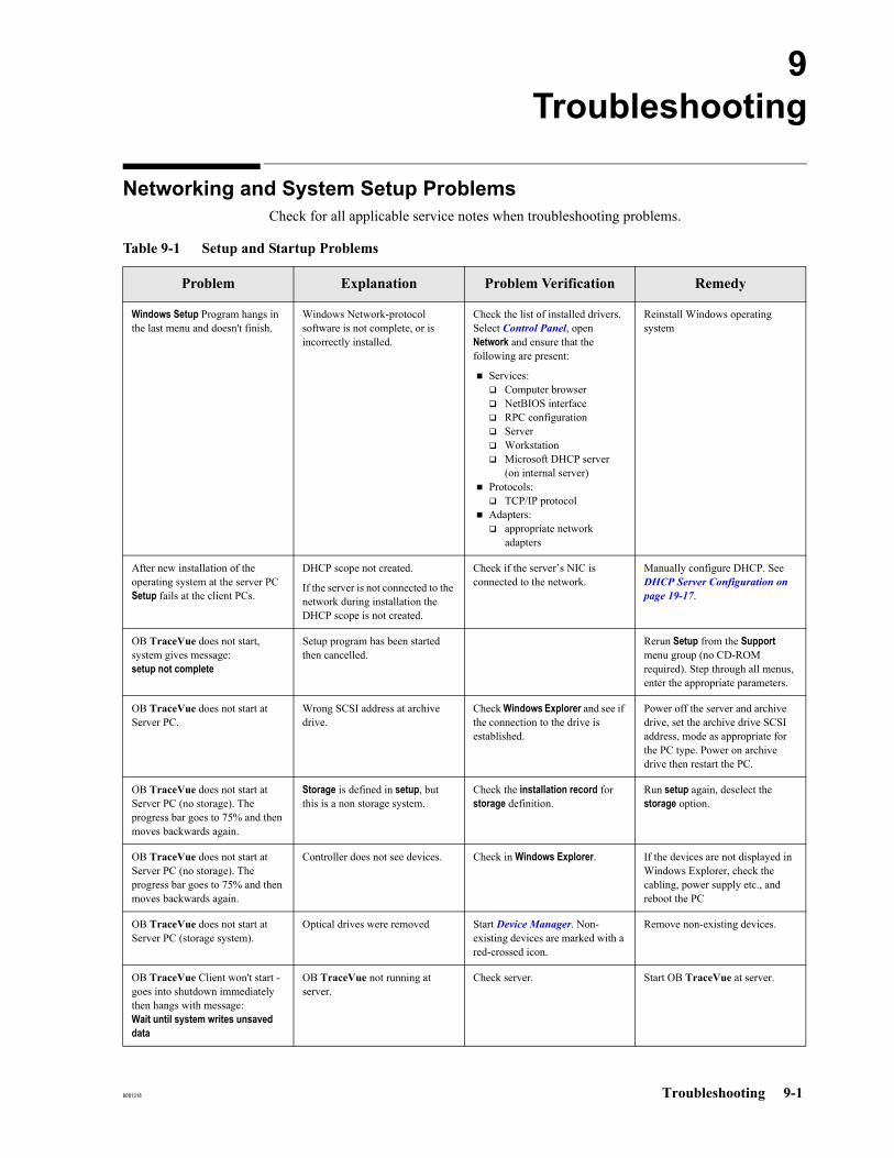
8081318 Troubleshooting 9-1
9Troubleshooting
Networking and System Setup ProblemsCheck for all applicable service notes when troubleshooting problems.
Table 9-1 Setup and Startup Problems
Problem Explanation Problem Verification Remedy
Windows Setup Program hangs in the last menu and doesn't finish.
Windows Network-protocol software is not complete, or is incorrectly installed.
Check the list of installed drivers. Select Control Panel, open Network and ensure that the following are present:
Services:Computer browser NetBIOS interfaceRPC configurationServerWorkstationMicrosoft DHCP server (on internal server)
Protocols:TCP/IP protocol
Adapters: appropriate network adapters
Reinstall Windows operating system
After new installation of the operating system at the server PC Setup fails at the client PCs.
DHCP scope not created.
If the server is not connected to the network during installation the DHCP scope is not created.
Check if the server’s NIC is connected to the network.
Manually configure DHCP. See DHCP Server Configuration on page 19-17.
OB TraceVue does not start, system gives message:setup not complete
Setup program has been started then cancelled.
Rerun Setup from the Support menu group (no CD-ROM required). Step through all menus, enter the appropriate parameters.
OB TraceVue does not start at Server PC.
Wrong SCSI address at archive drive.
Check Windows Explorer and see if the connection to the drive is established.
Power off the server and archive drive, set the archive drive SCSI address, mode as appropriate for the PC type. Power on archive drive then restart the PC.
OB TraceVue does not start at Server PC (no storage). The progress bar goes to 75% and then moves backwards again.
Storage is defined in setup, but this is a non storage system.
Check the installation record for storage definition.
Run setup again, deselect the storage option.
OB TraceVue does not start at Server PC (no storage). The progress bar goes to 75% and then moves backwards again.
Controller does not see devices. Check in Windows Explorer. If the devices are not displayed in Windows Explorer, check the cabling, power supply etc., and reboot the PC
OB TraceVue does not start at Server PC (storage system).
Optical drives were removed Start Device Manager. Non-existing devices are marked with a red-crossed icon.
Remove non-existing devices.
OB TraceVue Client won't start - goes into shutdown immediately then hangs with message: Wait until system writes unsaved data
OB TraceVue not running at server.
Check server. Start OB TraceVue at server.

Networking and System Setup Problems
9-2 Troubleshooting 8081318
Client does not connect to server. 1. Physical connection interrupted.
2. Server not working3. Wrong client PC name.4. Share on Server not
established.
1. Check Switch.2. Check Server.3. Check PC names - use
Control Panel/Network.4. Check share with
Windows Explorer.
1. Adjust workgroup name.2. Start server before clients.3. Adjust PC names.4. Establish server share.
OB TraceVue does not start after changing a PC name.
You didn't run OB TraceVue setup after changing the PC name. The new PC name must be entered into the database.
Check the installation record (OB TraceVue Support group icon). This shows the PC name used by OB TraceVue.
Power off, restart the PC, re run OB TraceVue Setup. Do not accept defaults, enter the correct parameters.
Windows hangs at server during startup, showing a blue screen.
Possible hardware problems, such as overheating.
CD-ROM light keeps flashing. Open CD-ROM drive, restart PC. Check devices.
Windows aborts in blue screen. Hardware incompatibility problems.
Check hardware and external devices such as adapter cards for version and compatibility.
Disconnect CD-ROM, restart. Reinstall Windows. Fix hardware problems.
Windows runs CHKDSK (CheckDisk) automatically.
File corruption detected and will be corrected automatically by CHKDSK.
Wait until CHKDSK has finished. If CHKDSK scans the archive media it can take over 20 minutes.
SHUTDOWN
(Server hangs)
One of the clients is waiting for input (such as acknowledgment of error-message).
Check clients. Acknowledge dialog-box at all clients.
DIALOG-box does not accept input.
You have multiple overlapping message boxes, and the active one is behind the one currently displayed.
Move current message box aside. Repeat this until you reach the active one that require input.
SYSTEM MESSAGE occurs during normal operation:serious error, restart PC No network messages displayed
Serious internal error. Press Restart to restart the PC. If this message keeps coming back then shutdown complete system (at server) and restart.
Make sure you restart the requested PC, and not the PC where you read the message!
External database cannot be installed on external server PC.
External server PC is already installed on the other PC.
Check all installed clients installation record.
De-install external database from other client. Install external database on desired PC.
Table 9-1 Setup and Startup Problems
Problem Explanation Problem Verification Remedy
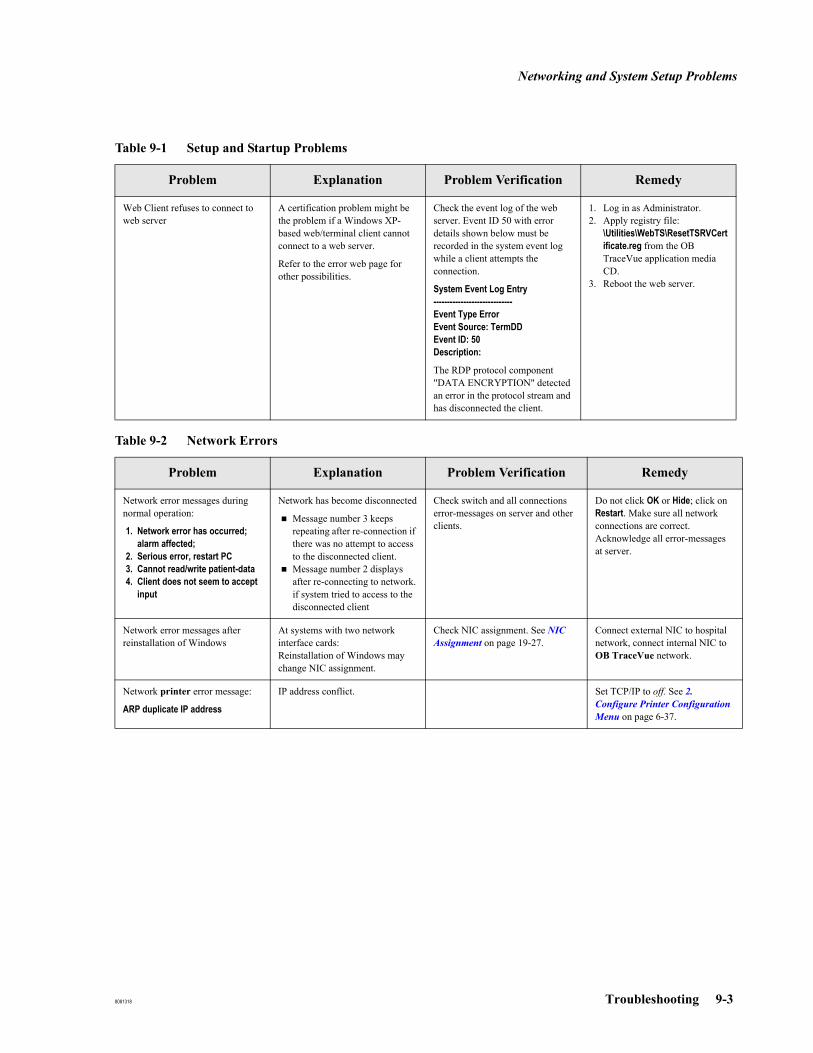
Networking and System Setup Problems
8081318 Troubleshooting 9-3
Web Client refuses to connect to web server
A certification problem might be the problem if a Windows XP-based web/terminal client cannot connect to a web server.
Refer to the error web page for other possibilities.
Check the event log of the web server. Event ID 50 with error details shown below must be recorded in the system event log while a client attempts the connection.
System Event Log Entry-----------------------------Event Type ErrorEvent Source: TermDDEvent ID: 50Description:
The RDP protocol component "DATA ENCRYPTION" detected an error in the protocol stream and has disconnected the client.
1. Log in as Administrator.2. Apply registry file:
\Utilities\WebTS\ResetTSRVCertificate.reg from the OB TraceVue application media CD.
3. Reboot the web server.
Table 9-2 Network Errors
Problem Explanation Problem Verification Remedy
Network error messages during normal operation:
1. Network error has occurred; alarm affected;
2. Serious error, restart PC3. Cannot read/write patient-data4. Client does not seem to accept
input
Network has become disconnected
Message number 3 keeps repeating after re-connection if there was no attempt to access to the disconnected client.Message number 2 displays after re-connecting to network.if system tried to access to the disconnected client
Check switch and all connections error-messages on server and other clients.
Do not click OK or Hide; click on Restart. Make sure all network connections are correct. Acknowledge all error-messages at server.
Network error messages after reinstallation of Windows
At systems with two network interface cards:Reinstallation of Windows may change NIC assignment.
Check NIC assignment. See NIC Assignment on page 19-27.
Connect external NIC to hospital network, connect internal NIC to OB TraceVue network.
Network printer error message:
ARP duplicate IP address
IP address conflict. Set TCP/IP to off. See 2. Configure Printer Configuration Menu on page 6-37.
Table 9-1 Setup and Startup Problems
Problem Explanation Problem Verification Remedy

Network Storage Access
9-4 Troubleshooting 8081318
Network Storage Access If there are access errors to the network storage location, perform these tests on the archive PC:
Checking NetworkConnectivity
Open a command prompt and type net use <network storage path> /user:<network storage user>
If network access is possible, then this connection can be made.
Checking FileAccess
Caution: Do not overwrite any existing file. After test is finished, do not remove any files created by the OB TraceVue system.
Start notepad.exe and try to write a txt file to the network storage location. This can be done in the base directory and in any subdirectory of the network storage location. Remove any files you create after the check.
Closing theNetwork
Connection
Open a command prompt and type net use /del <network storage path>

Hardware Problems
8081318 Troubleshooting 9-5
Hardware Problems
Table 9-3 Hardware Problems
Problem Explanation Problem Verification Remedy
FLOPPY drive error message displayed No disk inserted Yellow light is on for 30 s; drive is working; then stops with error.
Intermittent problem with drive mechanism.
When yellow light is on, slightly press eject button to fully engage drive carriage.
Intermittent errors with HDD and SCSI-devices.
Cable connection or SCSI termination incorrect.
Check that the external cable from SCSI card to drive is intact and correctly fitted. The pins at small connectors are very fragile.Check that the internal cable from SCSI card to HDD is intact and correctly fitted.
Connect cables correctly. Replace if necessary.
Intermittent errors with HDD and SCSI devices.
SCSI termination incorrect. Check internal bus termination:Terminator is connected to last connector of the ribbon-cable or termination jumper installed on last HDD (depends on HW)Check external bus termination:Terminator is installed at last external device.Check SCSI BIOS Setup. Make sure that the SCSI termination is set to Automatic.
Install terminators correctly.
Correct SCSI BIOS settings.
Intermittent errors with HDD and SCSI devices.
MO-drive settings incorrect. Check MO drive settings. Make sure that the mode and address settings are configured for the appropriate PC type.
Enter correct MO drive settings.
Soundcard not working. Cable connection, interrupt-conflict, alarm-configuration.
Verify interrupts (not critical at client; but could be a conflict with lightpen at server).Verify wire connection to speaker.Check Control Panel for volume setting and system sounds enabled. Verify sounds.Remove soundcard and check if internal speaker generates sound.
1. Adjust lightpen IRQ accordingly.
2. Replace speaker.3. Reinstall driver.
UPS not recognized. System error message: Cannot connect to UPS
Wrong cable, setup-parameters
PowerChute software must be available in program groupMake sure you use the correct cable. Use the cable that is in the UPS-box. Do NOT use general RS-232 fetal monitor cable.
Workaround if everything fails: Disable PowerChute software in program group, but leave the power-connections in place.
CD-ROM not working. Check that:The CD-ROM drive is connected.The jumper at the back of the CD-ROM drive is set to Cable Select.The CD-ROM drive is connected to the Master.
Serial Port Server not working.
Replace serial port server. See Replacing a Serial Port Server on page 6-27.
Unable to complete modem setup.
Modem not detected or malfunction.
Check using Add/Remove Hardware Troubleshooting Wizard in Control Panel.
Check device port; replace cable or modem; verify working analog phone line.

Fetal Monitor Connection / Data Acquisition Problems
9-6 Troubleshooting 8081318
Fetal Monitor Connection / Data Acquisition Problems
Table 9-4 Fetal Monitor / Data Acquisition Problems
Problem Explanation Problem Verification Remedy
No traces from M1350A after installing RS-232 System Interface.
1. RS422-I/F in fetal monitor is plugged in (and takes precedence).
2. Wrong connector used (Barcode 9pin D-sub on processor-board).
3. Wrong cable.
1. Check I/F-cards.2. Check connector:
Bar-code (wrong) is on processor board.System (correct) is on system board M1350-66536.
3. Cable: M1380-61612.
1. Remove RS422-card; so only RS-232-IF is plugged in or adjust system setting to RS-232-IF according to FM manual.
2. Use correct connector and cable.
3. Use correct connector and cable.
No traces from M1351/53A after installing RS-232Sys-IF.
Wrong I/F board, wrong firmware revision, wrong cable.
Check I-F board and firmware rev. (print error-log on fetal monitor).
Cable: M1380-61613.
Connector: HPIB-type 25pin.
Verify I/F: M1353-66531(E).
Verify firmware: A.02.02.
Use correct HW as described; no mode setting required.
No traces from non-HP/Agilent/Philips fetal monitor or from analog FMs.
Mode not adjusted at fetal monitor; see FM manual.
Wrong cable / converter.
1. Shutdown OB TraceVue at this client.
2. Start program FM-Spy from OBTV support group.
if monitor-ID is displayed correctly then cable/converter are ok.if no monitor-ID is displayed then cable problem or wrong converter.
Adjust mode at fetal monitor.
No traces from any type of Fetal Monitor.
Setup was run but port settings were not selected.
NA Re-run setup / select correct port settings.

Application Problems
8081318 Troubleshooting 9-7
Application Problems
Table 9-5 Application Problems
Problem Explanation Problem Verification Remedy
STORAGE does not work; message: cannot access optical disk drive.
MO-drive switched on after server-start.
Optical disk accessed viaWindows Explorer at server or client.
Check Windows Explorer: is connection to drive established?
Check all PCs for Windows Explorer accessing optical disk.
Shutdown Server. Power off optical drives. Switch optical drives back on. Start Server. Start clients.
Close all openWindows Explorers at all PCs.
Patient list does not display all beds.
You are logged-in as user Philips.
Note: Never create/edit/delete patient related data when you are logged on as an Philips user.
Verify user identify. Log-in as regular user with permission to see all beds.
A message is displayed saying that the external server PC is not running.
External server PC installed and configured but not started.
Does the external server run? Start up external server.
Cannot log in as Philips user Users can change the password Reinstall OB TraceVue at the sever. See Restoring the OB TraceVue Philips Password on page 18-10.
Documents or Statistics not enabled in the printing dialog
No external server PC Check if the external server PC is configured and running
Start external server
No template files available Check if the templates are available. In the Printing dialog, open Properties, click Documents or Statistics tab.
Copy templates. See Installing Word and Excel Templates on page 6-46.
Office not installed Check if Excel or Word is installed, and can be started
Install Office. See Installing and Configuring Microsoft Office 2007 on page 6-42.
Office .NET programmability support not installed
Check if .NET Programmability Support is installed.
Install .NET Programmability Support. See Install .NET Programmability Support on page 6-45.
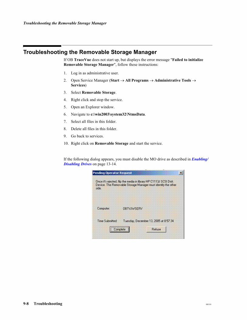
Troubleshooting the Removable Storage Manager
9-8 Troubleshooting 8081318
Troubleshooting the Removable Storage ManagerIf OB TraceVue does not start up, but displays the error message "Failed to initialize Removable Storage Manager", follow these instructions:
1. Log in as administrative user.
2. Open Service Manager (Start → All Programs → Administrative Tools → Services)
3. Select Removable Storage.
4. Right click and stop the service.
5. Open an Explorer window.
6. Navigate to c:\win2003\system32\NtmsData.
7. Select all files in this folder.
8. Delete all files in this folder.
9. Go back to services.
10. Right click on Removable Storage and start the service.
If the following dialog appears, you must disable the MO drive as described in Enabling/Disabling Drives on page 13-14.
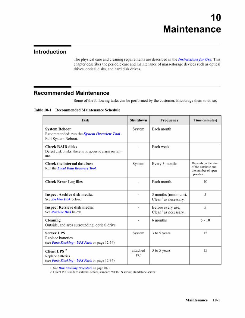
Maintenance 10-1
10Maintenance
IntroductionThe physical care and cleaning requirements are described in the Instructions for Use. This chapter describes the periodic care and maintenance of mass-storage devices such as optical drives, optical disks, and hard disk drives.
Recommended MaintenanceSome of the following tasks can be performed by the customer. Encourage them to do so.
Table 10-1 Recommended Maintenance Schedule
Task Shutdown Frequency Time (minutes)
System RebootRecommended: run the System Overview Tool - Full System Reboot.
System Each month
Check RAID disks Defect disk blinks; there is no acoustic alarm on fail-ure.
- Each week
Check the internal databaseRun the Local Data Recovery Tool.
System Every 3 months Depends on the size of the database and the number of open episodes.
Check Error Log files - Each month. 10
Inspect Archive disk media. See Archive Disk below.
- 3 months (minimum).Clean1 as necessary.
5
Inspect Retrieve disk media. See Retrieve Disk below.
- Before every use.Clean1 as necessary.
5
Cleaning Outside, and area surrounding, optical drive.
- 6 months 5 - 10
Server UPS Replace batteries(see Parts Stocking - UPS Parts on page 12-34)
System 3 to 5 years 15
Client UPS 2Replace batteries(see Parts Stocking - UPS Parts on page 12-34)
attached PC
3 to 5 years 15
1. See Disk Cleaning Procedure on page 10-32. Client PC, standard external server, standard WEB/TS server, standalone server

Caring for Optical Drives and Media
10-2 Maintenance
Caring for Optical Drives and MediaFor OB TraceVue Revision F onwards, network based storage is the exclusive method of data storage. The following information is provided for support purposes for systems prior to Revision F.
Caring for Optical Drives (standalone drives only)
Caution: DO NOT attempt to open an optical drive unit. It is a Class 1 Laser Product.
Allow a minimum clearance of 70-80mm (3 inches) behind the rear panel and in front of the optical disk drive, to allow air circulation.
Position the drive away from sources of particulate contamination such as the floor, frequently-used doors and walkways, printers, stacks of supplies that collect dust, and smoke filled rooms.
To avoid contamination building up in the drive, clean the drive’s surroundings and the exterior of its cover at least every three months, especially all airflow openings.
DO NOT use a drive lens cleaning kit.
If dust is a problem in the area where an OB TraceVue optical drive is installed, ensure that the optical disk drive cabinet is installed in the optical disk drive cabinet. Refer to Optical Disk Drive Cabinet on page 13-17.
Caring for Optical Disks
Storage andHandling
When storing or handling optical disks, follow the environmental precautions illustrated on the label sheet provided in their packaging.
Archive Disk To avoid contamination building up on the disk in the OB TraceVue archive drive, at least every three months inspect BOTH sides of the disk and clean as necessary. Follow the instructions given with the magneto-optical media cleaning kit provided.
No shutdown is required to complete this simple procedure.
Retrieve Disk A disk should not be left in the retrieve drive longer than is necessary. Remove the disk from the drive, make sure the drive’s door is shut, and store the disk in its card sleeve in a suitable environment.
Before use, inspect BOTH sides of the disk and clean as necessary. Follow the instructions given with the magneto-optical media cleaning kit provided.

Rebooting the WEB/Terminal Server
Maintenance 10-3
Disk CleaningProcedure
1. Start the OB TraceVue Optical Disk Manager
2. Select Change optical disk for archiving.
3. Select Insert the last disk for archiving.
4. The disk is ejected; clean the disk
5. Insert the cleaned disk, follow the on-screen instructions.
Optical DiskCleaning Kit
An appropriate cleaning kit, such as the kit supplied with an archiving system, is required to clean an optical disk. Be sure to follow the instructions included with the cleaning kit carefully.
Rebooting the WEB/Terminal ServerTo reboot the WEB/Terminal Server without rebooting the whole OB TraceVue system follow the steps below:
1. At the Terminal Server PC start the Terminal Services Manager.
2. Select all running sessions.
3. Use Action → Send Message to send a free text notification to the selected sessions.
4. Select Action → Disconnect.
5. Reboot the WEB/Terminal Server PC.
Virus ProtectionSee the Integration Guide for virus protection information.
External Database Performance
10-4 Maintenance
External Database Performance
Note This applies only to systems with an external database
To maintain or optimize the performance of the external database server the size of the external database must be kept under control. If the database becomes too large and the database server therefore becomes too slow, episodes must be removed.
Manual Purge Use the External Database Administration Tool to purge patient data.
Automatic Purge OB TraceVue D.01.00 (or later) supports automatic purge of closed episodes from the external database.
You may specify a time after which closed episodes are automatically removed from the external database in the System Manager’s Configuration screen, External DB tab at the internal server PC.
The default purge time is 2 years.
See also the External Database Guide.
Caution: When upgrading from D.00.02 or earlier: After you have upgraded the internal server PC make sure to set the purge time to the required value before starting the external database server PC. Once you have upgraded and started OB TraceVue at the external database server PC, closed episodes will be removed from the external database if they are older than the specified “purge time”.

8081318 System Support 11-1
11System Support
OverviewThe following picture shows an overview of the tools and methods that can be used to support an OB TraceVue system:
Ethernet
OB TraceVueExternal Server PC
OB TraceVueInternal Server PC
OBTV Client PCs
Modem
Modem
Serial
Serial
Remote SupportPC
Modem
Serial
OB TraceVue Product Remote Support via Terminal Service Client
TerminalServiceClient
SystemOverview
Tool
System Overview Tool
11-2 System Support 8081318
System Overview ToolUse the System Overview tool to:
see an overview of all PCs on one OB TraceVue system.
start, stop and reboot a complete system from one PC.
start, stop and reboot individual clients (including remote clients) from one PC.
A detailed description of how to use the System Overview Tool is in the System Administration and Configuration Guide.
The Integration Guide contains instructions on how to configure the DCOM service to allow the System Overview tool to pass a firewall.
RestrictionsOB TraceVue Web clients are not handled. They can only be viewed in the tool.OB TraceVue is not started automatically on WEB/Terminal server PCs. If required, select the WEB/Terminal server PC(s) and click Start OB TraceVue to start manually.
Using with OB TraceVue Remote LAN Clients / HA Server Pair
To remotely administer a PC connected to a different network segment name resolution and routing must be configured appropriately.
If no name resolution is available the host names (or alias name, for HA pair) can be configured manually:For each client connected to a different network segment, enter a line containing the IP address and the hostname (or alias name, for HA pair) in the file %WINDIR%\system32\drivers\etc\hosts.
To verify, that routing and name resolution is configured correctly, use the command ping <host> where <host> is the hostname (or alias name, for HA pair) of the remote PC without domain extensions.

Remote Support Using Remote Desktop
8081318 System Support 11-3
Remote Support Using Remote Desktop
Overview
Remote support via Remote Desktop connection allows to connect to OB TraceVue servers for administration purposes. To use remote administration:
1. Go to Control Panel -> System -> Remote (tab).
2. Enable the Enable Remote Desktop on this Computer checkbox.
It is possible to connect to the servers by using a Terminal Services Client.
On the remote support PC the Remote Desktop Client displays a new desktop of the connected server. It is not possible to share the screen of the connected server. Although OB TraceVue may be running on that PC it is not visible in the Remote Desktop session.
Supported PCs The Remote Desktop is prepared onOB TraceVue internal server andOB TraceVue external server
Note The preferred PC for the Remote Desktop Server is the OB TraceVue external server. This has least impact on system stability and performance.Do not set up a modem for remote support on the Web Terminal Server PC.
Licences A license is not required for remote administration.
Operating Systems Remote Desktop Clients are available for computers running Windows 2000, Windows NT, Windows ME, Windows 98, Windows 95 and others.
Remote Support Using Remote Desktop
11-4 System Support 8081318
Installation To install remote support
At the customer’s site:
At the Terminal Services Server, open System (Control Panel).Click on the tab Remote.Enable Remote Desktop on this computer and add “user” to the remote users.Configure and install an incoming modem connection,
At the support office:
Install Terminal Services Client when using Windows NT, Windows 2000, Windows 9x or Windows ME.Configure and install an outgoing modem connection.
Enabling Terminal Services Server Remote Support on a Server PC
The Terminal Services Server is initially disabled and must be enabled to allow a connection. At the selected OB TraceVue server:
Go to Services.
Start Terminal Services.
Caution: When ending the remote support session stop the Terminal Services Server at the OB TraceVue server PC to avoid unauthorized access.
Modem Setup
Note Remote support modems are usually connected to serial port B (COM2).
Add a modem device.
Configure the modem.
Customer’s site: Configure an incoming connection.
Support office: Configure an outgoing connection.
For details refer to Installing a Modem on page 6-40.
Remote Support Using Remote Desktop
8081318 System Support 11-5
Installing Terminal Services Client
The OB TraceVue Client CD-ROM contains the Windows NT4 / Windows 2000 and Windows 9x / Windows ME version of the Windows Terminal Services Client software.
To install the Terminal Services Client software run \Utilities\TerminalServerClient\msrdpcli.exe from OB TraceVue Client CD-ROM.
Follow the on-screen instructions.
Note The Windows Terminal Services Client software is only required for remote support via Terminal Services. Do not use for WEB clients.
Remote Support Using Remote Desktop
11-6 System Support 8081318
Using Terminal Services Client
The Terminal Services Client displays a new desktop of the connected server. To avoid mixing up the remote support PC desktop and the Terminal Services Client desktop do not use full screen mode for the terminal session. Alternatively use a different display scheme on the remote support PC.
To Connect to theOB TraceVue
Server
Establish a network connection between the remote support PC and the OB TraceVue internal or external server PC. Use a standard LAN or dialup network (modem and telephone line) connection. Refer to Installing a Modem on page 6-40 and to the Windows help.
Start new Remote Desktop connection:
On Windows Server 2003 or Windows XP: Go to Start → Programs → Accessories → Communication → Remote Desktop Connection.
On other operating systems: Go to Start → Programs → Remote Desktop Connection.
Select a screen area for the terminal session which is less than the resolution of the remote support PC.
To Disconnect fromthe OB TraceVueServer and Close
the Connection
In the Terminal Services Client window click Start → Shut Down.
In the Shutdown Windows dialog select Log off user.
Caution: Do not choose Shutdown or Restart. This shuts down the OB TraceVue server PC.
Using SystemOverview Tool
within TerminalServices Client
It is possible to use the System Overview Tool within a Terminal Services Client session.
If the tool is used to
start or stop OB TraceVue
reboot a client
reboot the whole system
Inform the customer in advance. A service person must be available at the OB TraceVue site to perform local actions if required.
Using OB TraceVuewithin Terminal
Services Clients
Starting OB TraceVue within a Terminal Services Client session adds a Web Client with the name of the remote support PC to the OB TraceVue system.

Log Files
8081318 System Support 11-7
Log FilesThe following table lists all OB TraceVue log files.
You can use GetLog to archive all log files in a single file. See GetLog on page 16-27.
Table 11-1 OB TraceVue Log Files
Log Location Size Comment
PC log Internal server PC:C:\tv2\logdata\<hostname>.log
≤ 6MB per file
Successes, warnings and errors during execution of OB TraceVue.
Startup log All PCs:C:\TraceVue.log
≤ 6MB
Typical: < 1KB
Check if OB TraceVue does not start.
Overwritten at each start of OB TraceVue.
WEB/Terminal server PC:C:\<hostname>.log (for each WEB/Terminal client)
≤ 6MB per file
Typical: < 1KB
HL7 log Internal server PC:C:\tv2\logdata\<hl7server>.hl7
≤ 6MB Successes, warnings and errors of the HL7 module.
Setup Error log
All PCs:C:\traceset.txt
Typical: < 2KB
Errors, that occurred in exe-cution of OB TraceVue Setup.
Overwritten at each start of OB TraceVue Setup.
Only available if Setup failed.
Configuration Backup log
Internal server PC:C:\tv2\logdata\CfgBkup.log
≤ 6MB Successes, warnings and errors of the offline Configu-ration Backup tool.
Local Recovery log
Internal server PC:C:\tv2\logdata\RecoveryTool.log
≤ 6MB Activity log of the recovery tool.
For a high availability sys-tem, there is a file with the same name on the Archive server (eg the external server), which contains the results of the ’optical recov-ery’ part of the Local Data Recovery.
Retrieve from Archive log
Internal server PC:C:\tv2\logdata\RFAWiz.txt
Typical:< 5KBadded per execution.
Activity log of the Retrieve from Archive Tool.

Log Files
11-8 System Support 8081318
System Overview Tool log
On the PC where SysView was started:C:\tv2\tools\sysview.txt
≤ 2MB
per file
If limit is reached, sys-view.txt is renamed to sysview_old.txt and a new sysview.txt is created.
Link Recovery log
On the Master PC:C:\tv2\tools\LinkRecover\ LinkRecoverMaster_Log.txt
Typical:< 5KB
Master activity log.
Overwritten at each start of the tool.
Master PC (direct connection) or Slave PC:C:\tv2\tools\LinkRecover\ Agent_<hostname>.txt
Typical:< 5KB
Agent activity log (steps per-formed on each PC)
Overwritten at each start of the tool.
Master PC:C:\tv2\tools\LinkRecover\ RecoveryMonitor.txt
Typical:< 5KB
Log file for the agent moni-toring process. Overwritten at each start of the tool.
Upgrade log Internal server PC:C:\obtv_upgrade.log
Typical:< 5KB
Migration of 1.64 Database.
Lists patients and configura-tion items which could not be upgraded.
Optical Disk Check log
Internal server PC:C:\disktool.log
Typical:< 10KB
Activity log.
Office Tem-plates
Office client(s):C:\doctemplates.log
Typical:≤ 6MB
Word and Excel Templates
Table 11-1 OB TraceVue Log Files
HP / Compaq Insight Management Software
8081318 System Support 11-9
HP / Compaq Insight Management Software
Note HP / Compaq Insight Manager is supplied with the ProLiant ML370 G2/G3 and ProLiant ML350 G4/G4P/ G5 PCs only.HP / Compaq Insight Manager requires the SNMP service. See Task 35: Network Security on page 5-33.
Introduction
HP / Compaq Insight Manager provides rapid access to detailed fault and performance information gathered by the Management Agents. Insight Manager helps maximize system uptime and performance and reduces the cost of maintaining the IT infrastructure by providing proactive notification of problems before those problems result in costly downtime.
Though Insight Manager may help you to manage the server hardware, it is not necessary for running OB TraceVue. It should be installed and maintained by qualified IT personnel only.
For detailed installation and configuration instructions and minimum system requirements refer to the HP / Compaq Management CDROM.
Management Agents
OB TraceVue is prepared for, and has been tested with, the HP ProLiant Support Pack preinstalled with OB TraceVue.
The Agents run on the PC to be monitored by the device manager software.
Due to operating system incompatibilities, the management agents must not be installed on internal servers, external servers, the servers of a high availability system and the corresponding PC that hosts the archive device.
On the OB TraceVue client PCs and the Web/Terminal PCs, the Management Agent software may be installed upon third party integration testing. Select DMI support during installation.
HP / Compaq Insight Manager
This software may be installed on a dedicated PC in the OB TraceVue network but it must not be on a PC running any OB TraceVue software. It lets you manage and review devices over the network.

HP / Compaq Insight Management Software
11-10 System Support 8081318
HP Insight Diagnostics Online Edition for Windows
This tool is pre-installed on the highend servers.
Configuration: To configure the Diagnostics software:
1. Launch the “HP System Management Homepage” shortcut from the desktop.
2. Go through the internet connection wizard (if it comes up).
set it up for LAN
leave the defaults for the proxy discovery
do not setup internet mail accounts
3. Click on yes if a ’security alarm’ is displayed.
4. Add https://127.0.0.1 to the trusted sites zone when prompted.
5. Logon using any local Windows administrator account.
6. Under “other agents” click on “HP Insight Diagnostics”.
7. In the “Survey” tab click on “Schedule Survey Capture”.
8. Set it to the desired interval, e.g. weekly, check all days and set the time to 23:55.
From now on, a report is generated automatically at the specified times. The output file is stored in C:\hp\hpdiags and has the following format:
survey<YYYY>-<MM>-<DD>-<HH>-<mm>-<ss>.xml
You can view this file using any XML viewer. You can also load the file from the Management Homepage in order to compare different logfiles to check for configuration changes.
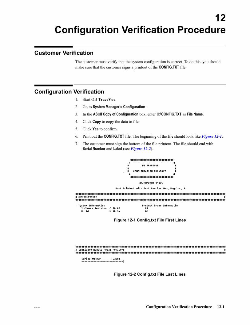
8081318 Configuration Verification Procedure 12-1
12Configuration Verification Procedure
Customer VerificationThe customer must verify that the system configuration is correct. To do this, you should make sure that the customer signs a printout of the CONFIG.TXT file.
Configuration Verification1. Start OB TraceVue.
2. Go to System Manager’s Configuration.
3. In the ASCII Copy of Configuration box, enter C:\CONFIG.TXT as File Name.
4. Click Copy to copy the data to file.
5. Click Yes to confirm.
6. Print out the CONFIG.TXT file. The beginning of the file should look like Figure 12-1.
7. The customer must sign the bottom of the file printout. The file should end with Serial Number and Label (see Figure 12-2).
Figure 12-1 Config.txt File First Lines
Figure 12-2 Config.txt File Last Lines

Configuration Verification
12-2 Configuration Verification Procedure 8081318

8081318 Component Installation (Upgrade/Repair) 13-1
13Component Installation (Upgrade/Repair)
IntroductionThis chapter provides brief installation instructions for hardware components. These components are supplied to upgrade or repair existing systems.
Any hardware settings or software procedures given are generic. Refer to the chapter in this manual that describes the particular PC you are working on.
For details about installing components such as a hard drive or CD-ROM drive, consult the User's Guide that comes with the PC you are working on. This tells you how to safely remove and replace items such the PC’s cover, or power supply. Instructions given here are OB TraceVue specific requirements and are additional to instructions given in the PC’s User’s Guide.
Static electricity can damage electronic components. To prevent damage, observe standard handling precautions. Refer to Electrostatic Handling Precautions on page 2-18.
When you have installed the hardware component you may have to install the driver software required to allow the PC to communicate with that component.
If the OB TraceVue shell is switched on, you cannot access the desktop. You must temporarily disable the Shell while you perform the repair or upgrade. Remember to switch it back on afterwards.
Software DistributionDriver software for OB TraceVue components is distributed on the OB TraceVue CD-ROM. For new components, driver software may be temporarily distributed on floppy disk until the OB TraceVue CD-ROM is updated.
Note Do not install driver software from another source (such as a printer CD-ROM or the web) unless specifically instructed to do so by, for example, a Service Note.
Floppy Disk The floppy drive fitted to an OB TraceVue PC is disabled after software installation.
To enable (or disable) floppy disk drives see Disable Flexible Disk Drives on page 5-35.

PC System Board Replacement
13-2 Component Installation (Upgrade/Repair) 8081318
PC System Board ReplacementIf you exchange the PC system board, you must flash the BIOS, if:
The BIOS revision is less than the revision originally shipped with the OB TraceVue PC or
If the original BIOS version shipped cannot be determined, and the current BIOS version on the PC is less than the revision on the OB TraceVue server CD-ROM for the specific PC model.
Note After you have flashed the BIOS, follow the instructions in the OB TraceVue Test and Inspection Matrix (Repair - PC (display, internal PC components) on page 2-16).Only use BIOS revisions on the OB TraceVue server CD-ROM (do not download BIOS revisions from the HP website).Check that the BIOS settings are correct: Refer to the appropriate chapter in this manual for the PC you are using.
Additional Memory For instructions on the installation of additional memory refer to the User’s Guide for the PC on which you are working.

Network Interface (LAN) Card
8081318 Component Installation (Upgrade/Repair) 13-3
Network Interface (LAN) CardFit the network interface card into the appropriate PC slot. The slot numbers are listed in the chapter for the appropriate PC type. When replacing a LAN card, you do not have to re- install its driver.
Refer to Second Network Interface Card on page 19-27.
PCI RS-232 Serial I/F Card
The PCI RS-232 Serial Interface card:
Is suitable for all PCs. It provides two additional RS-232 ports, COM3 and COM4.Has no switches, or jumpers. All settings are made using the software driver.Requires one PC IRQ. This IRQ is automatically selected by the PCI system.Provides two identical 9-pin D-type serial ports.
M1380-66501 is used for all PCs except for the dc7600/7700/rp5700, which require M1380-60501.
Fitting the PCI RS-232 Serial Interface Card
1. Power down the PC and fit the PCI Serial Interface card in the correct PCI slot. Refer to the section in this manual for the PC you are working on.
2. Windows should detect the new hardware and ensure that the driver is installed. If it does not, and you have to install the driver manually Windows 2003 will ask for the path to the driver so it can automatically select the required files and install the device. The path is: C:\Drivers\Serial
3. Test the port using FMSpy.

PCI RS-232 Serial I/F Card
13-4 Component Installation (Upgrade/Repair) 8081318
Using FMSpy to Test the COM Ports
You can use the FMSpy utility to test each COM port on a PC, and test signal transmission from the fetal monitor(s) connected to that PC.
At the PC where you wish to run FMSpy:
1. Exit OB TraceVue (if this is an OB TraceVue client, there is no need to exit OB TraceVue at the server or at other clients).
2. Go to OB TraceVue Support → Spy
3. Select each port in turn then from the drop-down list.The field next to the Port field is color coded to show you the current status of the port.
For more information about the FMSpy utility, refer to Fetal Monitor Spy (FMSpy) on page 16-23.
CD-ROM Drive
8081318 Component Installation (Upgrade/Repair) 13-5
CD-ROM Drive
Caution: When installing or replacing the CD-ROM drive check drive letter assignment after you have installed the new drive. Refer to Checking and Changing Drive Letters on page 19-22.
The CD-ROM drive fits on a mass-storage device shelf.
For general instructions on the installation of mass-storage devices refer to the User’s Guide for the PC on which you are working. More detailed information is available in the PC’s Service Manual.
Make sure that:
The CD-ROM drive is connected to the special CD-ROM ribbon cable (red connector), rather than the same IDE port as the IDE hard disk.
The jumper at the back of the CD-ROM drive is set to Cable Select
The CD-ROM drive is connected to the Master connector.
Primary Hard Disk Drive
Caution: When installing or replacing a hard disk check drive letter assignment after you have installed the new disk. Refer to Checking and Changing Drive Letters on page 19-22.
The primary hard disk drive fits on a mass-storage device shelf.
For general instructions on the installation of mass-storage devices refer to the User’s Guide for the PC on which you are working. More detailed information is available in the PC’s Service Manual.
When you have installed the hardware, start a new installation or recovery, as appropriate.
Caution: All data on the hard disk will be lost.
SCSI Host Adapter
13-6 Component Installation (Upgrade/Repair) 8081318
SCSI Host AdapterThis applies only to a server with storage, and to the highend external server ML 350 G4/G4p and ML350 G5.
Host Adapter Types
M1381-66404 (EVO D510, D530)This card supports the SCSI Ultra2 protocol. The card is fitted with HDTS68 Wide internal and external bus connectors.
M1381-66405 (ProLiant ML 350G4, dc7100)This card supports the SCSI Ultra2 protocol. The card is fitted with HDTS68 Wide internal and external bus connectors.
ProLiant ML 370The PC has an onboard SCSI host adapter.
M1381-66403 (ProLiant ML 350G4P/G5, dc7600/7700/rp5700)This card supports the SCSI Ultra 160 and Ultra2 protocol. The card is fitted with HDTS68 (LVD/SE) internal and external bus connectors.
Slot Assignment
Refer to the appropriate chapter for the PC you are installing:
Slot Assignments for Compaq Evo D510 on page 24-2Slot Assignments for HP Compaq D530 on page 25-2Slot Assignments for HP Compaq dc7100 on page 31-2Slot Assignments for HP Compaq dc7600 on page 32-2Slot Assignments for HP Compaq dc7700 on page 33-2Slot Assignments for HP rp5700 on page 34-2Slot Assignments for Compaq ProLiant ML370 G2 on page 26-1Slot Assignments for HP ProLiant ML370 G3 on page 27-1Slot Assignments for HP ProLiant ML350 G4 on page 28-1Slot Assignments for HP ProLiant ML350 G4P on page 29-1Slot Assignments for HP ProLiant ML350 G5 on page 30-1
SCSI BIOS
Refer to the appropriate chapter for the PC you are installing:
SCSI BIOS Settings for Compaq Evo D510 on page 24-5SCSI BIOS Settings for HP Compaq D530 on page 25-5SCSI BIOS Settings for HP Compaq dc7100 on page 31-5SCSI BIOS Settings for HP Compaq dc7600 on page 32-6SCSI BIOS Settings for HP Compaq dc7700 on page 33-5SCSI BIOS Settings for HP rp5700 on page 34-5SCSI BIOS Settings for Compaq ProLiant ML370 G2 on page 26-3
Secondary Hard Disk Drive (for Storage Systems)
8081318 Component Installation (Upgrade/Repair) 13-7
SCSI BIOS Settings for HP ProLiant ML370 G3 on page 27-3SCSI BIOS Settings for HP Proliant ML350 G4 on page 28-5SCSI BIOS Settings for HP Proliant ML350 G4P on page 29-4SCSI BIOS Settings for HP Proliant ML350 G5 on page 30-6
Secondary Hard Disk Drive (for Storage Systems)
Caution: When installing or replacing a hard disk check drive letter assignment after you have installed the new drive. Refer to Checking and Changing Drive Letters on page 19-22.
When upgrading from a non-storage system to a storage system, you must install a second hard disk. For general instructions on the installation of mass-storage devices refer to the User’s Guide for the PC on which you are working. More detailed information is available in the PC’s Service Manual.
Note The secondary disk drive discussed in this section is the D:Drive!
Disk Installation
IDE Hard Disk(Evo D530)/SATA
Hard Disk (dc7100/dc7600/dc7700/
rp5700)
The second drive should be jumpered to Cable Select (CS), and fitted into the next free mass storage device shelf.
Refer to the appropriate chapter for the PC you are installing:
IDE Configuration for HP Compaq D530 on page 25-4.SATA Configuration for HP Compaq dc7100 on page 31-4.SATA Configuration for HP Compaq dc7600 on page 32-4.SATA Configuration for HP Compaq dc7700 on page 33-4SATA Configuration for HP rp5700 on page 34-4
Windows Installation
1. After restart run Disk Management.
2. If the Write Signature and Upgrade Wizard appears, close it by pressing the Esc button.
3. Click Disk 1 in the lower part of the Disk Manager window with the right mouse button and select Write Signature. Acknowledge.
4. Click graphical representation of the unallocated partition of Disk 1 with the right mouse button and select New Partition… from the dropdown box.

Secondary Hard Disk Drive (for Storage Systems)
13-8 Component Installation (Upgrade/Repair) 8081318
5. The Create Partition Wizard appears, click Next.
6. Select Primary Partition, click Next
7. Keep the maximum as default value for the partition size, click Next
8. Assign D: as drive letter for the new HD, click Next
9. The Format Partition window appears. Enter the following settings:File System to use: NTFSAllocation unit size: DefaultVolume label: TV BackupCheck the selection box Perform Quick Format
10. Click Next and Finish to start formatting the disk. Close the Computer Management console. It takes a few minutes until the disk is formatted and you can install OB TraceVue.
Optical Drives
8081318 Component Installation (Upgrade/Repair) 13-9
Optical Drives
Caution: When installing or replacing optical drives check drive letter assignment after you have installed the drives. Refer to Checking and Changing Drive Letters on page 19-22.
Optical drives are external devices. These devices are “daisy-chained” on the SCSI bus.
In case the SCSI host adapter has a wide connector the cable between the PC and the first narrow optical drive must be a special cable with active termination.
The SCSI host adapter automatically detects when external SCSI devices are installed.
Caution: The final optical drive must have a termination resistor installed.
Ensure that the maximum length of the SCSI cables is not exceeded. See Cable Lengths below.
HP Optical DriveSettings
On the back panel of the drive, make sure:
SCSI address: archive drive: 1; retrieve drive: 25.2 or 9.1 GB drives: Device Mode: 3 - Direct Access / Verify On.
Put a terminator on the archive drive if there is no retrieve drive, otherwise put a terminator on the retrieve drive.
Plasmon OpticalDrive Settings
On the back panel of the drive make sure:
SCSI address (switch 1-3): archive drive: 1; retrieve drive: 2
Force verify (switch 4) : on
Enable fast SCSI (switch 5): on
Device Type (switch 6): on (direct access)
Put a terminator on the archive drive if there is no retrieve drive, otherwise put a terminator on the retrieve drive.
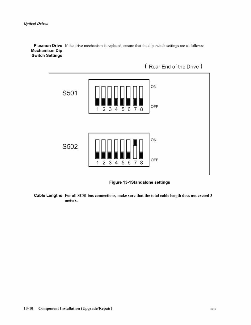
Optical Drives
13-10 Component Installation (Upgrade/Repair) 8081318
Plasmon DriveMechamism DipSwitch Settings
If the drive mechanism is replaced, ensure that the dip switch settings are as follows:
Figure 13-1Standalone settings
Cable Lengths For all SCSI bus connections, make sure that the total cable length does not exceed 3 meters.
Optical Medium Changers (Autochanger/Jukebox)
8081318 Component Installation (Upgrade/Repair) 13-11
Optical Medium Changers (Autochanger/Jukebox)Optical medium changers and optical drives are external devices. These devices are "daisy-chained" on the SCSI bus.
An optical medium changer consists of three separate devices:
the changerthe first optical drive andthe second optical drive
Each device maintains its own SCSI address.
OB TraceVue supports one optical medium changer plus an additional standalone optical drive.
Caution: HP Jukebox: Do not turn power to STANDBY in the HP jukebox until you are sure the SCSI bus is inactive. Removing power from a SCSI peripheral when the bus is active can result in data loss and/or indeterminate bus states.
Shutdown server PC and switch off before placing jukebox standby/on switch to STANDBY. To shut jukebox off completely, unplug power cord.
Plug the jukebox into power and place the standby/on switch to ON before powering on server PC.
Caution: Ensure that you do not use write-protected media in a medium changer.
Installation HP Jukebox: Remove the shipping screw and mailslot shipping bracket. Store the screw in a safe place for later use if the changer needs to be re-shipped.Plasmon library: Unlock the lift lock screw at the rear, and remove the foam from the mail slot.Check the SCSI address of the changer and the optical drives (see Changer Settings for HP and Plasmon Autochanger (SCSI ID)).Connect SCSI cables.
For HP Jukeboxes only: connect terminator. Plasmon jukeboxes are autoterminated internally and do not require external termination.
The final optical drive must have a terminator installed, (except the Plasmon autochanger which has an integrated terminator) and must always be installed at the end of the SCSI bus.
Ensure that the maximum length of the SCSI cables is not exceeded. See Cable Lengths below.

Optical Medium Changers (Autochanger/Jukebox)
13-12 Component Installation (Upgrade/Repair) 8081318
Changer Settingsfor HP and PlasmonAutochanger (SCSI
ID)
Autochanger: SCSI ID 4Optical disk drive 1: SCSI ID 5Optical disk drive 2: SCSI ID 6
You must manually change the shipped defaults of the SCSI IDs of both the HP and Plasmon medium changers to those IDs shown above.
Refer to the Optical Autochanger users guide on how to change the SCSI IDs:
HP Optical Jukebox Model 125ex/220mx Service Manual.
Plasmon Gx Libraries Gx24 - Gx80 - UDO/MO Driver User and Service Manual.
Note You do not need to change the default drive letters assigned by the operating system.You do not need to change any other factory defaults for either autochanger. It is necessary to cycle the autochanger power after the addresses have been changed.
Combination ofStandalone OpticalDrive and Medium
Changer
HP: If an HP optical medium changer is installed in combination with an HP optical drive, the cable between the medium changer and the drive requires active termination.
Plasmon: A Plasmon optical medium changer can be combined with only a Plasmon optical drive. The first device on the SCSI bus is the Plasmon drive. The second device is the autochanger. The optical disk drive’s SCSI address is 1. The other addresses are as shown in Plasmon Optical Drive Settings.
The LVD cables 453564054001 (5m) and HP C7522A (10m) may be used to connect a Plasmon medium changer. If either of these cables is fitted, no MO drive may be connected to the SCSI bus.
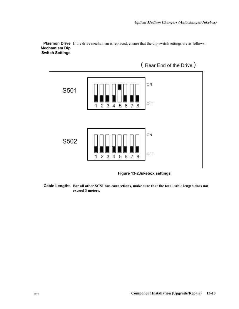
Optical Medium Changers (Autochanger/Jukebox)
8081318 Component Installation (Upgrade/Repair) 13-13
Plasmon DriveMechamism DipSwitch Settings
If the drive mechanism is replaced, ensure that the dip switch settings are as follows:
Figure 13-2Jukebox settings
Cable Lengths For all other SCSI bus connections, make sure that the total cable length does not exceed 3 meters.
Configure Removable Storage Manager (RSM) for Archiving
13-14 Component Installation (Upgrade/Repair) 8081318
Configure Removable Storage Manager (RSM) for Archiving
General Configuration
Remove unused devices (applicable to stand alone drives and jukebox).
Open the Removable Storage Manager configuration:
1. Press Start.
2. Select All Programs → Administrative Tools → Computer Management.
3. In the left tree view, select Storage → Removable Storage.
4. Expand Removable Storage (press "+" in the left tree view).
5. Expand Libraries.
6. Delete all unavailable drives/libraries from Removable Storage Manager:
a. Right click on the library or drive which is marked with a cross, and select Delete.
b. Confirm the deletion.
Configuration of RSM for Plasmon and HP Jukeboxes
No special configuration of RSM is required if a Jukebox is being used. OB TraceVue operates with the defaults of RSM, which are:
The library is enabled.
The drives of the library are enabled.
Configuration of RSM for Plasmon and HP Standalone MO Drives
Ensure that all connected drives are disabled. See Enabling/Disabling Drives.
Enabling/Disabling Drives
To enable/disable drives in Removable Storage Manager:
1. Open Removable Storage Manager configuration and expand the item "libraries".
2. Right click on the drive to configure and select Properties → General.
3. Check/uncheck Enable drive to enable/disable the drive.

Supported Archiving Device Combinations
8081318 Component Installation (Upgrade/Repair) 13-15
Supported Archiving Device CombinationsMake sure that wide SCSI devices are connected as the first device, and narrow devices as the second.
Older hardware with a VHDCI SCSI connector require the additional adapter cable (453563471631) to connect to the first device.
Continue installation of stand-alone MO drives, see OB TraceVue Setup on page 18-2.
Table 13-1 Supported Archiving Device Combinations
First Device Second Device
Hewlett-Packard Devices
HP 5.2 or 9.1 MO Drive
with 1.0m SCSI cable (453563279291)
none
HP 5.2 or 9.1 MO Drive
with 1.0m SCSI cable (453563279291)
HP 5.2 or 9.1 MO Drive
with 1.0m SCSI cable (453563199431)
HP Jukebox
with 1.5m SCSI cable (453564026431)
none
HP Jukebox
with 1.5m SCSI cable (453564026431)
HP 5.2 or 9.1 MO Drive
with 1.0m SCSI cable (453563279291)
Plasmon Devices
Plasmon MO Drive
with 1.5m SCSI cable (453564026431)
none
Plasmon MO Drive
with 1.5m SCSI cable (453564026431)
Plasmon MO Drive
with 1.0m SCSI cable (453563477251)
Plasmon Jukebox
with 1.5m SCSI cable (453564026431)
none
Plasmon MO Drive
with 1.5m SCSI cable (453564026431)
Plasmon Jukebox
with 1.0m SCSI cable (453563477251)
Plasmon Jukebox
with 5.0m SCSI cable (453564054001)
None
Mixed Devices
Plasmon MO Drive
with 1.5m SCSI cable (453564026431)
HP 5.2 or 9.1 MO Drive
with 1.0m SCSI cable (453563279291)

Supported Archiving Device Combinations
13-16 Component Installation (Upgrade/Repair) 8081318
Continue installation of optical Medium changer, see Optical Medium Changers (Jukeboxes) on page 19-31.

Optical Disk Drive Cabinet
8081318 Component Installation (Upgrade/Repair) 13-17
Optical Disk Drive CabinetThe Optical Disk Drive Cabinet is designed to protect the archiving disk and archive drive from gradual contamination by dust and other particulates.
The Optical Disk Drive Cabinet is used to house one optical disk drive when used as the optional archive drive for an OB TraceVue system.
Caution: Do not place or store anything other than the optical drive and its current disk inside the cabinet.
The empty space around the drive is required to maintain low operating temperatures.
Before Installing the Optical Disk Drive Cabinet
Plan where the Optical Disk Drive Cabinet will be installed.
Do not extend the standard SCSI cables supplied with the optical drive.Clear sufficient space close to the OB TraceVue server for the cabinet. Do not install the cabinet where it will be exposed to direct sunlight. The Optical Disk Drive Cabinet is not intended to house both the archive and the optional retrieve drive. The retrieve drive cabinet may be stacked on top of the archiving drive cabinet.
If the OB TraceVue archiving system is running:1. Make sure that no optical disks are loaded in the drive(s).2. Shut down OB TraceVue at the server. Client PCs will automatically shut down.3. Shut down the server PC.4. Switch off the archiving disk drive and, if fitted, the retrieve drive. 5. Disconnect all cabling, and put the drive(s) to one side out of the way.

Optical Disk Drive Cabinet
13-18 Component Installation (Upgrade/Repair) 8081318
Installing the Optical Disk Drive Cabinet
1. Place the drive cabinet as close to its final location as you can.The cabinet weighs about 11.5 kg (25.5 lbs) empty.
2. Feed all the cabling to the drive into the cabinet through the foam lined slot in its rear panel.This cabling could include:
The SCSI cable from the PC to the archive drive. The SCSI cable to the retrieve drive, if present.The power cable for the drive.
3. Connect the SCSI cabling to the drive, then connect the power cable.
4. If the optical disk drive's power switch is located on its rear panel, set the power switch to on. The switch is not accessible from the rear of the Optical Disk Drive cabinet.
5. Place the drive centrally on the floor of the cabinet, so allowing space for air circulation around the optical drive.
6. Place the cabinet in its final location.Make sure the cabling leaves the cabinet neatly, with no or minimal gaps in the foam seal.
7. Switch on power to the optical disk drive.
8. Restart OB TraceVue.
MaintenanceThe drive cabinet requires no maintenance except occasional external cleaning.
Before cleaning the drive cabinet:
Eject the disk from the drive.Make sure that you have read Caring for Optical Drives (standalone drives only) on page 10-2 and Caring for Optical Disks on page 10-2.
Caution: Do not use under-diluted or strong solvents.
The foam lined cable slot in the rear of the drive cabinet and the door seal cannot withstand abuse by such agents.
These components are not available as separate parts.
Clean the drive cabinet as described in the Instructions for Use.
Repair
The drive cabinet has no exchangeable or repairable parts. If the cabinet is damaged, full unit replacement is required.
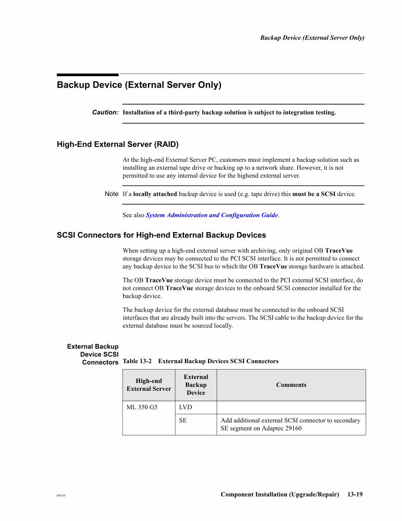
Backup Device (External Server Only)
8081318 Component Installation (Upgrade/Repair) 13-19
Backup Device (External Server Only)
Caution: Installation of a third-party backup solution is subject to integration testing.
High-End External Server (RAID)
At the high-end External Server PC, customers must implement a backup solution such as installing an external tape drive or backing up to a network share. However, it is not permitted to use any internal device for the highend external server.
Note If a locally attached backup device is used (e.g. tape drive) this must be a SCSI device.
See also System Administration and Configuration Guide.
SCSI Connectors for High-end External Backup Devices
When setting up a high-end external server with archiving, only original OB TraceVue storage devices may be connected to the PCI SCSI interface. It is not permitted to connect any backup device to the SCSI bus to which the OB TraceVue storage hardware is attached.
The OB TraceVue storage device must be connected to the PCI external SCSI interface, do not connect OB TraceVue storage devices to the onboard SCSI connector installed for the backup device.
The backup device for the external database must be connected to the onboard SCSI interfaces that are already built into the servers. The SCSI cable to the backup device for the external database must be sourced locally.
External BackupDevice SCSIConnectors Table 13-2 External Backup Devices SCSI Connectors
High-end External Server
External Backup Device
Comments
ML 350 G5 LVD
SE Add additional external SCSI connector to secondary SE segment on Adaptec 29160

Backup Device (External Server Only)
13-20 Component Installation (Upgrade/Repair) 8081318
SCSI Bus LengthMaximum
LVD: Maximum SCSI bus length = 12m.
SE: Maximum SCSI bus length = 3m
Standard External Server
RequiredComponents
To replace a defective internal tape drive, make sure you have the following components:
Internal tape drive.Mounting screws.Kit containing mounting rails and screws.
Installation 1. Put the jumper in the position CS (cable select).For Compaq Evo D510, and HP Compaq D530 PC only; the tape drive is connected to IDE bus 2, and you must put the jumper in the position Cable select (CS).
For HP Compaq dc7100/7600 PCs; both the CD-ROM and the tape drive are connected to the single IDE bus (identified as “primary IDE bus”). You must put the jumper in the position Cable select (CS).
2. Replace the defective tape drive.3. Connect the drive to the Slave connector:
a. Find the CD-ROM device inside the computer.b. Locate the cable that connects the CD-ROM to the motherboard.c. Attach the open connector to the tape drive.
ML 350 G4p LVD Add additional external SCSI connector to primary SCSI connector on the motherboard. Maximum SCSI bus length = 12m.
SE Add additional external SCSI connector to secondary SE segment on Adaptec 29160.
ML 350 G4 LVD Add additional external SCSI connector to primary SCSI connector on the motherboard.
SE Replace Symbios SYM8953U to Adaptec 29160 SCSI controller. Add additional external SCSI con-nector to secondary SE segment on Adaptec 29160.
ML 370 G3 LVD Add additional external SCSI connector to SCSI con-nector Port 1 on motherboard.
SE
ML 370 G2 LVD Add additional external SCSI connector to SCSI con-nector B on motherboard.
SE
Table 13-2 External Backup Devices SCSI Connectors
High-end External Server
External Backup Device
Comments

Backup Device (External Server Only)
8081318 Component Installation (Upgrade/Repair) 13-21
4. Connect the power cable:a. Locate your computers power supply and find an unused power cable.b. Plug the power cable into the back of the tape drive, with the beveled edge up.
5. For the dc7700 only:
a. Replace defective SATA tape drive.
b. Connect the power cable.
c. Connect the SATA cable to the SATA bus (identified as SATA 2 connector on the motherboard).
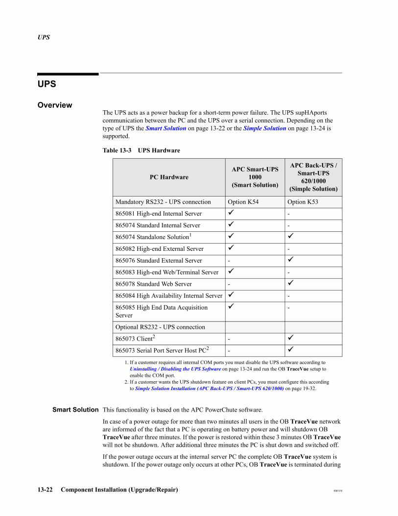
UPS
13-22 Component Installation (Upgrade/Repair) 8081318
UPS
OverviewThe UPS acts as a power backup for a short-term power failure. The UPS supHAports communication between the PC and the UPS over a serial connection. Depending on the type of UPS the Smart Solution on page 13-22 or the Simple Solution on page 13-24 is supported.
Smart Solution This functionality is based on the APC PowerChute software.
In case of a power outage for more than two minutes all users in the OB TraceVue network are informed of the fact that a PC is operating on battery power and will shutdown OB TraceVue after three minutes. If the power is restored within these 3 minutes OB TraceVue will not be shutdown. After additional three minutes the PC is shut down and switched off.
If the power outage occurs at the internal server PC the complete OB TraceVue system is shutdown. If the power outage only occurs at other PCs, OB TraceVue is terminated during
Table 13-3 UPS Hardware
PC HardwareAPC Smart-UPS
1000(Smart Solution)
APC Back-UPS / Smart-UPS
620/1000(Simple Solution)
Mandatory RS232 - UPS connection Option K54 Option K53
865081 High-end Internal Server -
865074 Standard Internal Server -
865074 Standalone Solution1
1. If a customer requires all internal COM ports you must disable the UPS software according to Uninstalling / Disabling the UPS Software on page 13-24 and run the OB TraceVue setup to enable the COM port.
865082 High-end External Server -
865076 Standard External Server -
865083 High-end Web/Terminal Server -
865078 Standard Web Server -
865084 High Availability Internal Server -
865085 High End Data Acquisition Server
-
Optional RS232 - UPS connection
865073 Client2
2. If a customer wants the UPS shutdown feature on client PCs, you must configure this according to Simple Solution Installation (APC Back-UPS / Smart-UPS 620/1000) on page 19-32.
-
865073 Serial Port Server Host PC2 -

UPS
8081318 Component Installation (Upgrade/Repair) 13-23
shutdown of the operating system at these PCs.
UPS
13-24 Component Installation (Upgrade/Repair) 8081318
Simple Solution This functionality is based on the Windows XP Professional built-in UPS service.
In case of a power outage for more than eight minutes the PC is shut down.
OB TraceVue gets terminated during shutdown of the operating system.
Connecting the UPS
Refer to Connect UPS on page 5-21.
UPS Driver Software
This software must be installed at OB TraceVue server PCs.
Installing the UPSSoftware
Refer to UPS Software:Smart Solution Installation (APC Smart-UPS 1000) on page 19-32.Simple Solution Installation (APC Back-UPS / Smart-UPS 620/1000) on page 19-32
Uninstalling /Disabling the UPS
Software
You may need to disable the UPS driver software if you have a standalone PC with 4 fetal monitors connected, and no UPS connected. If you do not disable the driver software, error messages may be displayed at regular intervals.
Smart Solution
1. Open Control Panel, click Add/Remove Programs.
2. Select PowerChute plus 5.2 from the list.
3. Click Add/Remove...
4. Click Yes to confirm you want to remove the driver.
5. Click No to all for “remove shared file ...."
6. Reboot the PC.
Simple Solution
1. Open Control Panel, select Power Options.
2. Select the UPS tab, click the Select… button.
3. Select (none) from the Select manufacturer: combo box.
4. Commit the new settings.
Network Based Storage
8081318 Component Installation (Upgrade/Repair) 13-25
Network Based StorageFor details on network based storage, see the chapter Network Based Storage.
Upgrading from Optical Disks to Network Based Storage
When upgrading an OB TraceVue system to use network based storage, use the optical disk migration tool to copy the content of all needed optical disks to the network storage location.
Preparation Do not remove optical disk hardware from archive PC until all needed optical disk are migrated.
Upgrade to NetworkStorage Location:
1. Create a backup using Backup Tool
2. Use OB TraceVue setup to configure the network storage location.
3. Startup OB TraceVue (this is to create an Archive Index on Storage location)
4. Start optical disk migration tool.
Select the optical disk to copy
Select the destination location
Run copy process
Select a new disk to copy if necessary
All disk data that are copied to the network storage location are now available for retrieve or RFA tool.
Optical Disk Migration Tool
The Optical Disk Migration tool is a wizard-based tool that allows you to copy the data stored on OB TraceVue optical disks to the network storage location. The tool supports standalone optical drives, and optical auto-changers where it is possible to select more than one disk.
Overview You use the wizard to select the disk for copying and the destination directory. The tool copies the data to the destination. If a directory already exists for the selected optical disk at the destination, the copy process is rejected. If an error occurs during copy or the user interrupts file copy process, the whole destination directory will be removed.
The Optical Disk Migration tool allows specifying a destination path and it allows entering user credentials that are used to access this location.
The Optical Disk Migration tool and the process of disk migration to a network storage location can run in parallel with OB TraceVue.
You are recommended to copy as many disks as possible during an upgrade in order to

Network Based Storage
13-26 Component Installation (Upgrade/Repair) 8081318
minimize the chance that old records required for retrieval are unavailable, remaining on as yet uncopied disks.

8081318 Repairing/Replacing Hardware and Media 14-1
14Repairing/Replacing Hardware and
Media
Repair Strategy
This section describes the full unit exchange or board-assembly exchange strategy applied to OB TraceVue.
Caution: When replacing harddisks, optical drives or CD-ROM drives check drive letter assignment after you have replaced the drives. Refer to Checking and Changing Drive Letters on page 19-22.
Hardware Defects
Hardware defects can be dealt with in the following ways:
Table 14-1 Repair methods and when to use them
Repair Method When to use it
Component Exchange or Replacement
For parts that are identified by exchange/replacement numbers (such as power-supply, fan, connectors, cables).
Full Unit Exchange Exchange an entire unit if you cannot identify an exchange or replacement part as the cause of the prob-lem, and for compact devices that should not be opened (such as transformer, modem).
Other Loose connections, wiring problems, mechanical mounts, installation problems.
Client PCs can be interchanged to temporarily substi-tute a defective PC.
A client PC can be upgraded to a server PC. This requires installation of special server equipment (e.g. additional memory). If patient data storage is required the PC also requires a SCSI host adapter and addi-tional HDD.

Repair Strategy
14-2 Repairing/Replacing Hardware and Media 8081318
Table 14-2 Repair Method
Equipment Repair Method
Peripheral Devices Component exchange/replacement as described in full unit exchange. Use part numbers printed on the component to help identify parts listed in this manual. Note that the UPS, transformer, and modem are only available as full unit exchange. You must not replace components or perform onsite repair.
Optical Medium Changers
1. Remove all media (do not use the Windows Explorer):
Eject the media through the OB TraceVue Optical Disk Manager.
If that does not work:Shut down OB TraceVue and eject the media through the Removable Storage Manager (RSM) (Computer Management → Storage → Removable Storage).
If that does not work:Shut down the PC and eject the media via the jukebox front panel.
If that does not work:Mechanical disassembly is required.
2. Install the shipping screw and mailslot shipping bracket (HP) or engage the lift lock screw (Plasmon) prior to shipping or relocating the medium changer/library.
Magneto Optical Drives
HP standalone drives: complete exchangePlasmon standalone drives: component repair (for example, internal drive mechanism)
PC Boards and Internal Components (soundcard, RS-232 card)
Component exchange/replacement as described in Component Exchange or Replacement. Use part numbers printed on component.
Assembly Kits (lightpen, soundcard-kit)
Replacement parts are available for individual components of the kit. For example, from the lightpen kit, you can order a lightpen card, or the lightpen stick plus holder plus cable.
OEM Parts Replacement parts are available for individual components.
Fuses Provide replacement fuses locally. The isolation transformer is supplied with extra fuses.
Batteries Replace these according to the part number printed on the batter-ies. Batteries in the client and server UPS can be replaced on site.

Repair Strategy
8081318 Repairing/Replacing Hardware and Media 14-3
Cable and Connec-tors
Replace these according to the part number printed on the cable or connector.
Wall Cabling Replace the cable by ordering a new cabling kit.
Table 14-2 Repair Method
Equipment Repair Method
Repair Strategy
14-4 Repairing/Replacing Hardware and Media 8081318
Replaceable Partsof Server and Client
PCs
Power supplyMotherboard and processorYou must exchange the complete board if any of the integrated connectors break.MemoryFloppy disk driveProcessor coolerHDD (Hard Disk Drive)Front panelRibbon cable to floppy disk driveRibbon cable to CD-ROM drivePower cablesBatteryDisplay
Additional Parts ofServer PC
CD-ROM driveSCSI-host adapterSCSI-HDD or IDE/SATA drive (type depends on PC model).Internal SCSI ribbon cable (type depends on HW):
SCSI bus terminated at the end of the cable (make sure to apply the terminator)SCSI bus terminated at last internal drive (make to apply the termination jumper)
All SCSI items on this list are for storage systems only.
Optional Parts forClient PC and
Server PC
LightpenLightpen board (PCI)RS-232 board (PCI)SpeakerNIC
Substituting a PC
When using a spare client (e.g. PC name SPARE) as a substitute for a defective client (e.g. PC name ORIGINAL) you must ensure that the spare client has the same settings and alarm distribution as the original client. Simply renaming SPARE to ORIGINAL is not permitted.
1. Uninstall OB TraceVue on the SPARE client.
2. Rename the spare PC to ORIGINAL and reboot.
3. Reinstall OB TraceVue on the client. This ensures that the substitute client has the same settings as the original client PC.
See Changing a Client PC Name on page 15-1 for details.
Software Media Defects
If an OB TraceVue CD-ROM breaks, or cannot be read you must order a replacement OB TraceVue media kit. The Windows operating systems are included in the CD media kit on separate media from the OB TraceVue application.

Parts Stocking
8081318 Repairing/Replacing Hardware and Media 14-5
Parts Stocking
12-digit part numbers (12NC) are Philips part numbers. Depending on the repair strategy they may not be orderable (e.g. the 12NCs for complete PCs or servers are typically not set up as oderable parts).Mxxxx-xxxxx are old Philips part numbers (can be translated to 12-digit part numbers).
Note: Internal Philips numbering (non-orderable; for reference only)HP = HP Spare Part number.Plasmon = Plasmon Spare Part number.EX = Exchange if appended as a suffix to HP Spare Part number.
Fetal Monitor Connections
Power Supply
Table 14-3 Parts Stocking - Fetal Monitor Connections
DescriptionPart Number
RemarksExchange New
Fetal Monitor Connection
See Fetal Monitor Connections, Available Protocol Conversion Kits and Cables
Table 14-4 Parts Stocking - Power Supply
DescriptionPart Number
RemarksExchange New
Power Supply
UPS and batteries See UPS Parts on page 14-30
Isolation Transformer 110V n/a 453563279351 M1389-60001
Isolation Transformer 220V n/a 453563279361 M1389-60002
Power cable adapter(PWR-CD-ADPTR 18-AWG 3-COND)
n/a 453563199391 to connect power-plug to isolation transformer outlet8120-5440
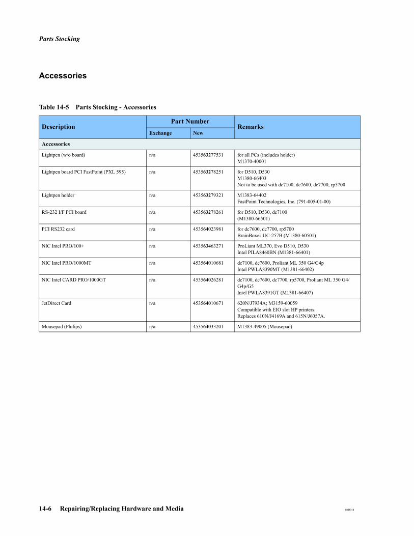
Parts Stocking
14-6 Repairing/Replacing Hardware and Media 8081318
Accessories
Table 14-5 Parts Stocking - Accessories
DescriptionPart Number
RemarksExchange New
Accessories
Lightpen (w/o board) n/a 453563277531 for all PCs (includes holder)M1370-40001
Lightpen board PCI FastPoint (PXL 595) n/a 453563278251 for D510, D530M1380-66403Not to be used with dc7100, dc7600, dc7700, rp5700
Lightpen holder n/a 453563279321 M1383-64402FastPoint Technologies, Inc. (791-005-01-00)
RS-232 I/F PCI board n/a 453563278261 for D510, D530, dc7100 (M1380-66501)
PCI RS232 card n/a 453564023981 for dc7600, dc7700, rp5700BrainBoxes UC-257B (M1380-60501)
NIC Intel PRO/100+ n/a 453563463271 ProLiant ML370, Evo D510, D530Intel PILA8460BN (M1381-66401)
NIC Intel PRO/1000MT n/a 453564010681 dc7100, dc7600, Proliant ML 350 G4/G4pIntel PWLA8390MT (M1381-66402)
NIC Intel CARD PRO/1000GT n/a 453564026281 dc7100, dc7600, dc7700, rp5700, Proliant ML 350 G4/G4p/G5Intel PWLA8391GT (M1381-66407)
JetDirect Card n/a 453564010671 620N/J7934A; M3159-60059Compatible with EIO slot HP printers.Replaces 610N/J4169A and 615N/J6057A.
Mousepad (Philips) n/a 453564033201 M1383-49005 (Mousepad)
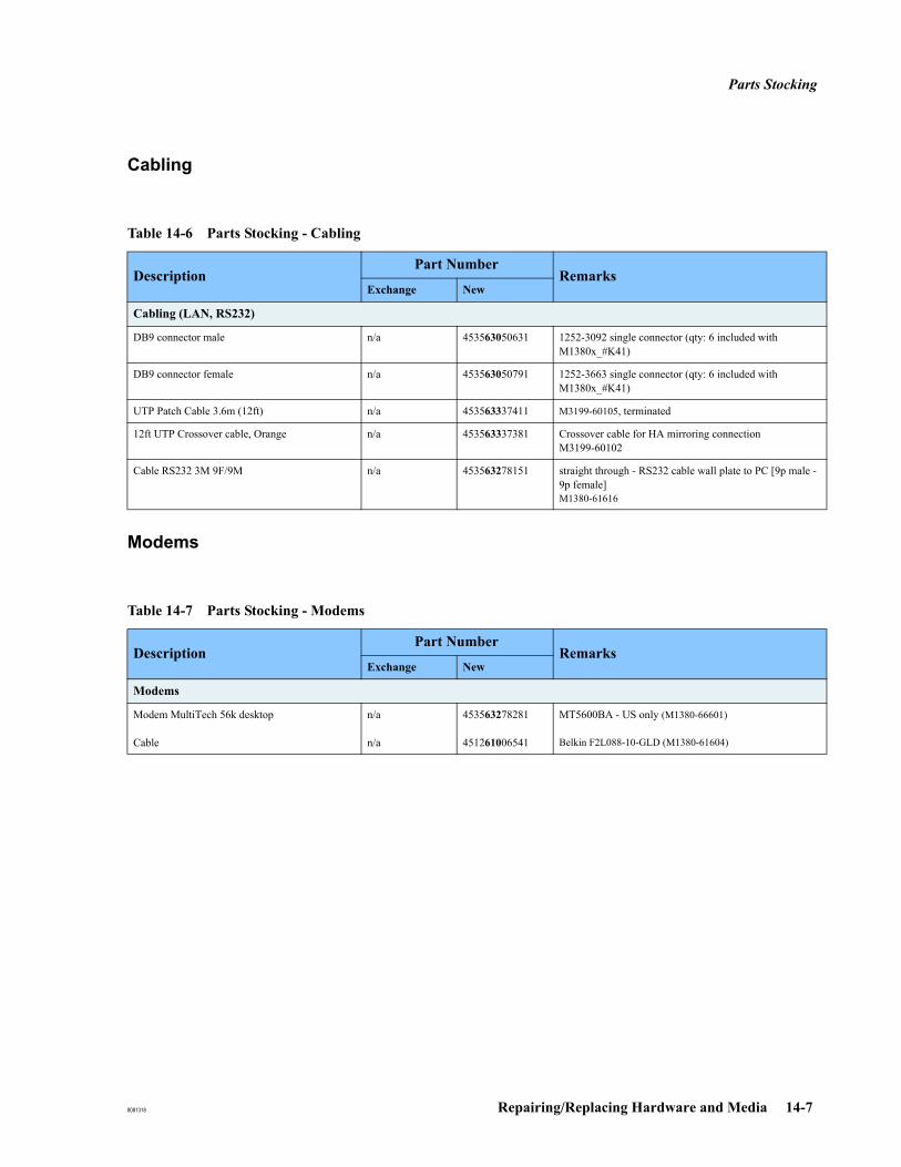
Parts Stocking
8081318 Repairing/Replacing Hardware and Media 14-7
Cabling
Modems
Table 14-6 Parts Stocking - Cabling
DescriptionPart Number
RemarksExchange New
Cabling (LAN, RS232)
DB9 connector male n/a 453563050631 1252-3092 single connector (qty: 6 included with M1380x_#K41)
DB9 connector female n/a 453563050791 1252-3663 single connector (qty: 6 included with M1380x_#K41)
UTP Patch Cable 3.6m (12ft) n/a 453563337411 M3199-60105, terminated
12ft UTP Crossover cable, Orange n/a 453563337381 Crossover cable for HA mirroring connectionM3199-60102
Cable RS232 3M 9F/9M n/a 453563278151 straight through - RS232 cable wall plate to PC [9p male -9p female]M1380-61616
Table 14-7 Parts Stocking - Modems
DescriptionPart Number
RemarksExchange New
Modems
Modem MultiTech 56k desktop
Cable
n/a
n/a
453563278281
451261006541
MT5600BA - US only (M1380-66601)
Belkin F2L088-10-GLD (M1380-61604)

Parts Stocking
14-8 Repairing/Replacing Hardware and Media 8081318
Switches
Table 14-8 Parts Stocking - Switches
DescriptionPart Number
RemarksExchange New
Switches
Switch HP ProCurve 2312 453564056751 453564057021 12 port (HP J4817A) non-routing, unmanagedJ4817-69101 (exch)J4817A-#ABA (new)
Switch HP ProCurve 2324 453564056541 453564057031 24 port (HP J4818A) non-routing, unmanagedJ4818-69001 (exch)J4818A-#ABA (new)
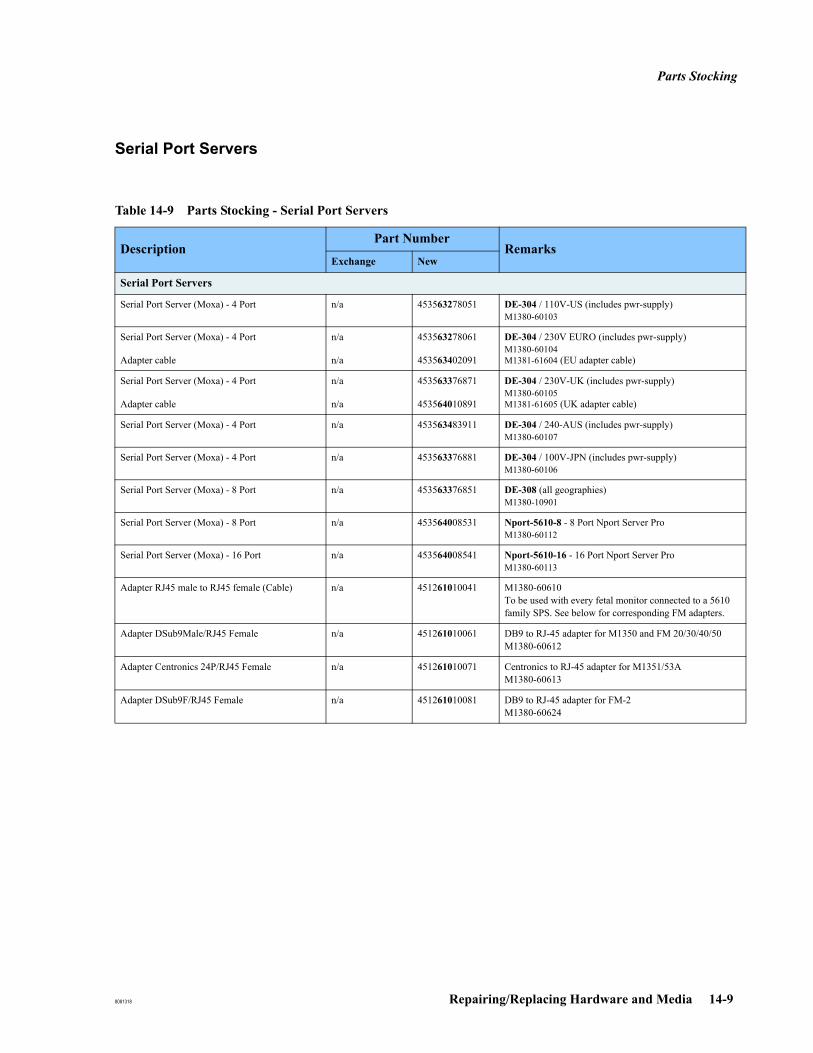
Parts Stocking
8081318 Repairing/Replacing Hardware and Media 14-9
Serial Port Servers
Table 14-9 Parts Stocking - Serial Port Servers
DescriptionPart Number
RemarksExchange New
Serial Port Servers
Serial Port Server (Moxa) - 4 Port n/a 453563278051 DE-304 / 110V-US (includes pwr-supply)M1380-60103
Serial Port Server (Moxa) - 4 Port
Adapter cable
n/a
n/a
453563278061
453563402091
DE-304 / 230V EURO (includes pwr-supply)M1380-60104M1381-61604 (EU adapter cable)
Serial Port Server (Moxa) - 4 Port
Adapter cable
n/a
n/a
453563376871
453564010891
DE-304 / 230V-UK (includes pwr-supply)M1380-60105M1381-61605 (UK adapter cable)
Serial Port Server (Moxa) - 4 Port n/a 453563483911 DE-304 / 240-AUS (includes pwr-supply)M1380-60107
Serial Port Server (Moxa) - 4 Port n/a 453563376881 DE-304 / 100V-JPN (includes pwr-supply)M1380-60106
Serial Port Server (Moxa) - 8 Port n/a 453563376851 DE-308 (all geographies)M1380-10901
Serial Port Server (Moxa) - 8 Port n/a 453564008531 Nport-5610-8 - 8 Port Nport Server ProM1380-60112
Serial Port Server (Moxa) - 16 Port n/a 453564008541 Nport-5610-16 - 16 Port Nport Server ProM1380-60113
Adapter RJ45 male to RJ45 female (Cable) n/a 451261010041 M1380-60610To be used with every fetal monitor connected to a 5610 family SPS. See below for corresponding FM adapters.
Adapter DSub9Male/RJ45 Female n/a 451261010061 DB9 to RJ-45 adapter for M1350 and FM 20/30/40/50M1380-60612
Adapter Centronics 24P/RJ45 Female n/a 451261010071 Centronics to RJ-45 adapter for M1351/53AM1380-60613
Adapter DSub9F/RJ45 Female n/a 451261010081 DB9 to RJ-45 adapter for FM-2M1380-60624

Parts Stocking
14-10 Repairing/Replacing Hardware and Media 8081318
Tape Drives
Table 14-10 Parts Stocking - Tape Drives
DescriptionPart Number
RemarksExchange New
Tape Drives
Tape Drive (Travan TR5; 20GB Int. IDE) n/a 453563464351 HP 480081-001 for D510
Certance/Seagate 20GB Travan Tape Drive (white)
3.5 inch black face plate5.25 inch black bezel (tape cover)
n/a
n/an/a
453564000011
453564000021453564000031
M3167-69016 (STT220000A-RDT)
M3167-69017 (for color correction)M3167-69018 (for color correction)
for D510, D530, dc7100, dc7600
Sony Tape Drive n/a 453564053981 Sony 40GB AIT turbo SATA Tape Drive int. for dc7700Appropriate media: Sony TAIT140C
HP Storage Works DAT72 USB External Drive n/a 453564079041 External HP USB Tape Drive for rp5700HP DW027A (USB Tape Drive)HP C8010A (DAT 72 Data Cartridge)HP C5709A (DDS cleaning cartridge)
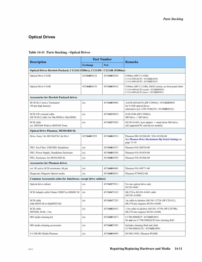
Parts Stocking
8081318 Repairing/Replacing Hardware and Media 14-11
Optical Drives
Table 14-11 Parts Stocking - Optical Drives
DescriptionPart Number
RemarksExchange New
Optical Drives Hewlett-Packard, C1114J (5200ex), C1114M / C1114R (9100mx)
Optical Drive 9.1GB 453564030121 453564030101 9100mx (HP C1114M)C1114-69014(CP) / 453563210301C1114-60014(CP) / 453563210231
Optical Drive 9.1GB 453564030151 453564030141 9100mx (HP C1114R); OEM version, no front panel labelC1114-69016(CP) (exch) / 453563399821C1114-60016(CP) (new) / 453563399811
Accessories for Hewlett-Packard drives
SE SCSI-2 Active Terminator(50-pin high density)
n/a 453564030091 A1658-62016(CP) (HP C2904A) / 453563208091 for 9.1GB optical drives (alternative p/n 1250-2548(CP) / 453563048341)
SCSI UW external cable(SE SCSI-2 cable 1m 50p HDM to 50p HDM)
n/a 453563199431 8120-5548 (HP C2908A)MO drive -> MO drive
SCSI cableext. HDTS68 Wide to HDTS50 Term.
n/a 453563279291 M1383-61601, host adapter -> stand alone MO-drive (all supported PC and Server models)
Optical Drive Plasmon, MO561RD-SL
Drive, Sony 14x MO Dr(F561 Int Drv) 453564043521 453564043511 Plasmon 900-101268-00 / 910-101268-00See Plasmon Drive Mechamism Dip Switch Settings on page 13-10
FRU, Fan Filter, UDO30D, Standalone n/a 453564043571 Plasmon 910-100736-00
FRU, Power Supply, Standalone Enclosure n/a 453564043581 Plasmon 910-101839-00
FRU, Enclosure, for MO561RD-SL n/a 453564043591 Plasmon 910-101966-00
Accessories for Plasmon drives
ext. SE active SCSI terminator, 68 pin n/a 453564049401 Plasmon 910-100771-00
Diagnostic Magneto Optical media n/a 453564049411 Plasmon 97706822-00
Common Accessories (also for Jukeboxes. except drive cabinet)
Optical drive cabinet n/a 453563279311 For one optical drive onlyM1383-64401
SCSI Adapter cable 0.8mm VHDCI to HD68F/1ft n/a 453563471631 ML370 to M1381-61601 cable (M1381-61608)
SCSI cable(68p HDTS M to 68pHDTS M)
n/a 453563477251 1m cable to jukebox (M1381-13724; HP C2911C).ML370 also requires M1381-61608.
SCSI cableHDTS68, M/M, 1.5m
n/a 453564026431 1.5m cable to jukebox (M1381-13750; HP C2979B),ML370 also requires M1381-61608.
MO media cleaning kit n/a 453564033671 C1700-88800CP / 453563210931Do not use C1700-88802(CP) lens cleaning disk!
MO media cleaning accessories n/a 453564027451 Includes cleaning fluid and cloth.C1700-88801(CP) / 453563210941
9.1 GB MO Media Plasmon n/a 453564044991 M1380-19301, Plasmon P9100E
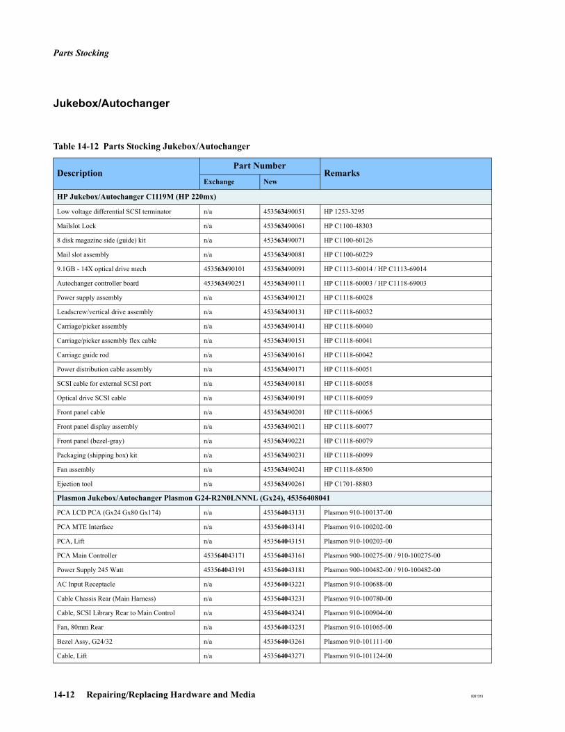
Parts Stocking
14-12 Repairing/Replacing Hardware and Media 8081318
Jukebox/Autochanger
Table 14-12 Parts Stocking Jukebox/Autochanger
DescriptionPart Number
RemarksExchange New
HP Jukebox/Autochanger C1119M (HP 220mx)
Low voltage differential SCSI terminator n/a 453563490051 HP 1253-3295
Mailslot Lock n/a 453563490061 HP C1100-48303
8 disk magazine side (guide) kit n/a 453563490071 HP C1100-60126
Mail slot assembly n/a 453563490081 HP C1100-60229
9.1GB - 14X optical drive mech 453563490101 453563490091 HP C1113-60014 / HP C1113-69014
Autochanger controller board 453563490251 453563490111 HP C1118-60003 / HP C1118-69003
Power supply assembly n/a 453563490121 HP C1118-60028
Leadscrew/vertical drive assembly n/a 453563490131 HP C1118-60032
Carriage/picker assembly n/a 453563490141 HP C1118-60040
Carriage/picker assembly flex cable n/a 453563490151 HP C1118-60041
Carriage guide rod n/a 453563490161 HP C1118-60042
Power distribution cable assembly n/a 453563490171 HP C1118-60051
SCSI cable for external SCSI port n/a 453563490181 HP C1118-60058
Optical drive SCSI cable n/a 453563490191 HP C1118-60059
Front panel cable n/a 453563490201 HP C1118-60065
Front panel display assembly n/a 453563490211 HP C1118-60077
Front panel (bezel-gray) n/a 453563490221 HP C1118-60079
Packaging (shipping box) kit n/a 453563490231 HP C1118-60099
Fan assembly n/a 453563490241 HP C1118-68500
Ejection tool n/a 453563490261 HP C1701-88803
Plasmon Jukebox/Autochanger Plasmon G24-R2N0LNNNL (Gx24), 45356408041
PCA LCD PCA (Gx24 Gx80 Gx174) n/a 453564043131 Plasmon 910-100137-00
PCA MTE Interface n/a 453564043141 Plasmon 910-100202-00
PCA, Lift n/a 453564043151 Plasmon 910-100203-00
PCA Main Controller 453564043171 453564043161 Plasmon 900-100275-00 / 910-100275-00
Power Supply 245 Watt 453564043191 453564043181 Plasmon 900-100482-00 / 910-100482-00
AC Input Receptacle n/a 453564043221 Plasmon 910-100688-00
Cable Chassis Rear (Main Harness) n/a 453564043231 Plasmon 910-100780-00
Cable, SCSI Library Rear to Main Control n/a 453564043241 Plasmon 910-100904-00
Fan, 80mm Rear n/a 453564043251 Plasmon 910-101065-00
Bezel Assy, G24/32 n/a 453564043261 Plasmon 910-101111-00
Cable, Lift n/a 453564043271 Plasmon 910-101124-00
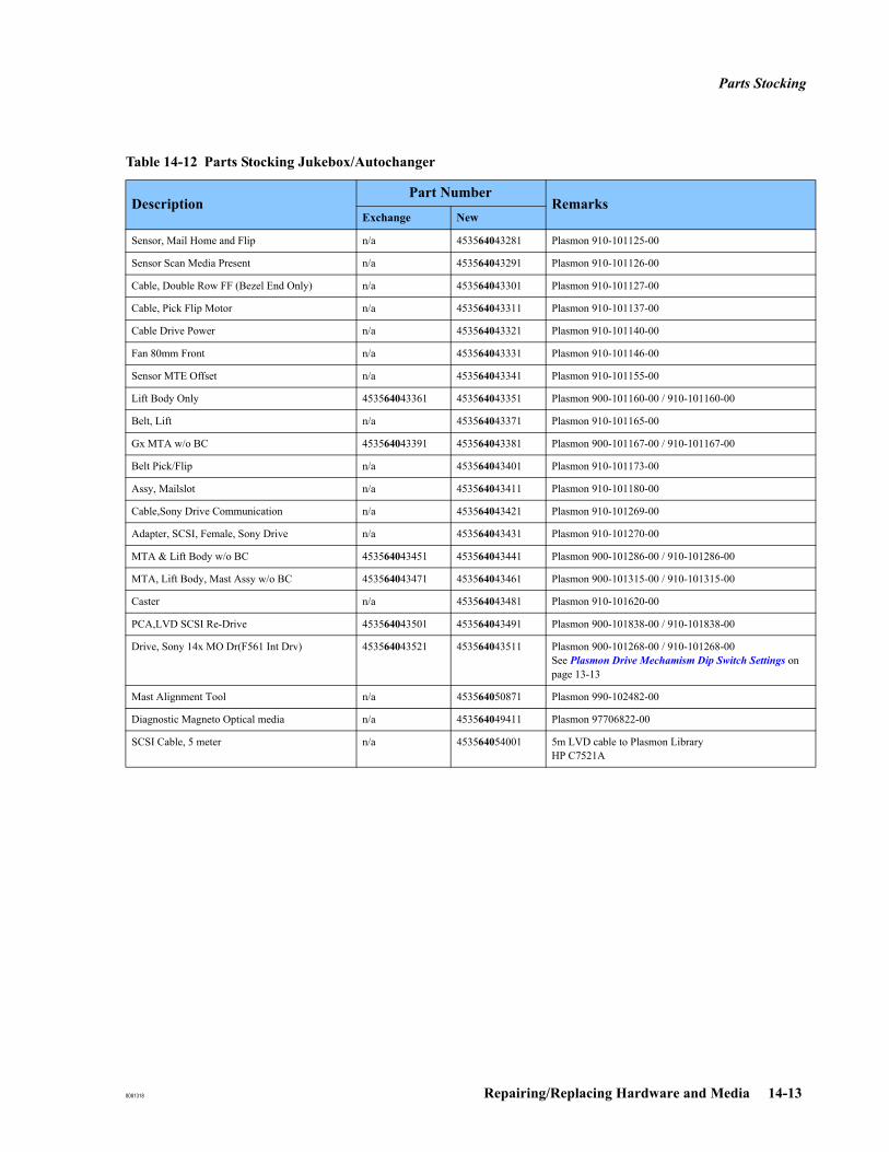
Parts Stocking
8081318 Repairing/Replacing Hardware and Media 14-13
Sensor, Mail Home and Flip n/a 453564043281 Plasmon 910-101125-00
Sensor Scan Media Present n/a 453564043291 Plasmon 910-101126-00
Cable, Double Row FF (Bezel End Only) n/a 453564043301 Plasmon 910-101127-00
Cable, Pick Flip Motor n/a 453564043311 Plasmon 910-101137-00
Cable Drive Power n/a 453564043321 Plasmon 910-101140-00
Fan 80mm Front n/a 453564043331 Plasmon 910-101146-00
Sensor MTE Offset n/a 453564043341 Plasmon 910-101155-00
Lift Body Only 453564043361 453564043351 Plasmon 900-101160-00 / 910-101160-00
Belt, Lift n/a 453564043371 Plasmon 910-101165-00
Gx MTA w/o BC 453564043391 453564043381 Plasmon 900-101167-00 / 910-101167-00
Belt Pick/Flip n/a 453564043401 Plasmon 910-101173-00
Assy, Mailslot n/a 453564043411 Plasmon 910-101180-00
Cable,Sony Drive Communication n/a 453564043421 Plasmon 910-101269-00
Adapter, SCSI, Female, Sony Drive n/a 453564043431 Plasmon 910-101270-00
MTA & Lift Body w/o BC 453564043451 453564043441 Plasmon 900-101286-00 / 910-101286-00
MTA, Lift Body, Mast Assy w/o BC 453564043471 453564043461 Plasmon 900-101315-00 / 910-101315-00
Caster n/a 453564043481 Plasmon 910-101620-00
PCA,LVD SCSI Re-Drive 453564043501 453564043491 Plasmon 900-101838-00 / 910-101838-00
Drive, Sony 14x MO Dr(F561 Int Drv) 453564043521 453564043511 Plasmon 900-101268-00 / 910-101268-00See Plasmon Drive Mechamism Dip Switch Settings on page 13-13
Mast Alignment Tool n/a 453564050871 Plasmon 990-102482-00
Diagnostic Magneto Optical media n/a 453564049411 Plasmon 97706822-00
SCSI Cable, 5 meter n/a 453564054001 5m LVD cable to Plasmon LibraryHP C7521A
Table 14-12 Parts Stocking Jukebox/Autochanger
DescriptionPart Number
RemarksExchange New
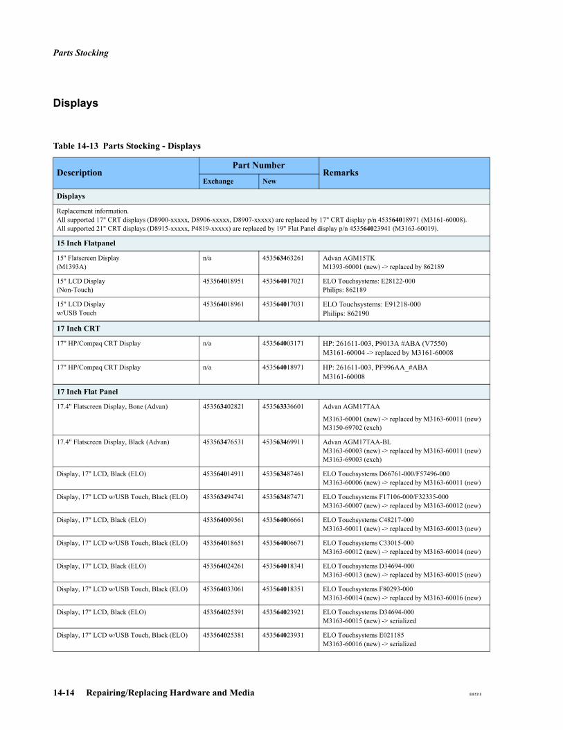
Parts Stocking
14-14 Repairing/Replacing Hardware and Media 8081318
Displays
Table 14-13 Parts Stocking - Displays
DescriptionPart Number
RemarksExchange New
Displays
Replacement information. All supported 17" CRT displays (D8900-xxxxx, D8906-xxxxx, D8907-xxxxx) are replaced by 17" CRT display p/n 453564018971 (M3161-60008).All supported 21" CRT displays (D8915-xxxxx, P4819-xxxxx) are replaced by 19" Flat Panel display p/n 453564023941 (M3163-60019).
15 Inch Flatpanel
15'' Flatscreen Display (M1393A)
n/a 453563463261 Advan AGM15TKM1393-60001 (new) -> replaced by 862189
15" LCD Display (Non-Touch)
453564018951 453564017021 ELO Touchsystems: E28122-000Philips: 862189
15" LCD Displayw/USB Touch
453564018961 453564017031 ELO Touchsystems: E91218-000Philips: 862190
17 Inch CRT
17" HP/Compaq CRT Display n/a 453564003171 HP: 261611-003, P9013A #ABA (V7550)M3161-60004 -> replaced by M3161-60008
17" HP/Compaq CRT Display n/a 453564018971 HP: 261611-003, PF996AA_#ABAM3161-60008
17 Inch Flat Panel
17.4" Flatscreen Display, Bone (Advan) 453563402821 453563336601 Advan AGM17TAA
M3163-60001 (new) -> replaced by M3163-60011 (new) M3150-69702 (exch)
17.4" Flatscreen Display, Black (Advan) 453563476531 453563469911 Advan AGM17TAA-BLM3163-60003 (new) -> replaced by M3163-60011 (new)M3163-69003 (exch)
Display, 17" LCD, Black (ELO) 453564014911 453563487461 ELO Touchsystems D66761-000/F57496-000M3163-60006 (new) -> replaced by M3163-60011 (new)
Display, 17" LCD w/USB Touch, Black (ELO) 453563494741 453563487471 ELO Touchsystems F17106-000/F32335-000M3163-60007 (new) -> replaced by M3163-60012 (new)
Display, 17" LCD, Black (ELO) 453564009561 453564006661 ELO Touchsystems C48217-000M3163-60011 (new) -> replaced by M3163-60013 (new)
Display, 17" LCD w/USB Touch, Black (ELO) 453564018651 453564006671 ELO Touchsystems C33015-000 M3163-60012 (new) -> replaced by M3163-60014 (new)
Display, 17" LCD, Black (ELO) 453564024261 453564018341 ELO Touchsystems D34694-000M3163-60013 (new) -> replaced by M3163-60015 (new)
Display, 17" LCD w/USB Touch, Black (ELO) 453564033061 453564018351 ELO Touchsystems F80293-000 M3163-60014 (new) -> replaced by M3163-60016 (new)
Display, 17" LCD, Black (ELO) 453564025391 453564023921 ELO Touchsystems D34694-000M3163-60015 (new) -> serialized
Display, 17" LCD w/USB Touch, Black (ELO) 453564025381 453564023931 ELO Touchsystems E021185M3163-60016 (new) -> serialized
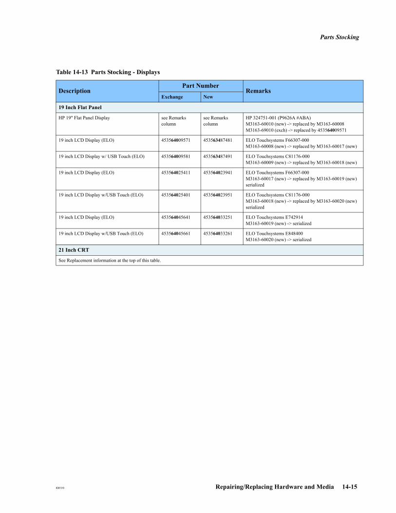
Parts Stocking
8081318 Repairing/Replacing Hardware and Media 14-15
19 Inch Flat Panel
HP 19" Flat Panel Display see Remarks column
see Remarks column
HP 324751-001 (P9626A #ABA)M3163-60010 (new) -> replaced by M3163-60008M3163-69010 (exch) -> replaced by 453564009571
19 inch LCD Display (ELO) 453564009571 453563487481 ELO Touchsystems F66307-000M3163-60008 (new) -> replaced by M3163-60017 (new)
19 inch LCD Display w/ USB Touch (ELO) 453564009581 453563487491 ELO Touchsystems C81176-000M3163-60009 (new) -> replaced by M3163-60018 (new)
19 inch LCD Display (ELO) 453564025411 453564023941 ELO Touchsystems F66307-000M3163-60017 (new) -> replaced by M3163-60019 (new) serialized
19 inch LCD Display w/USB Touch (ELO) 453564025401 453564023951 ELO Touchsystems C81176-000M3163-60018 (new) -> replaced by M3163-60020 (new) serialized
19 inch LCD Display (ELO) 453564045641 453564033251 ELO Touchsystems E742914M3163-60019 (new) -> serialized
19 inch LCD Display w/USB Touch (ELO) 453564045661 453564033261 ELO Touchsystems E848400M3163-60020 (new) -> serialized
21 Inch CRT
See Replacement information at the top of this table.
Table 14-13 Parts Stocking - Displays
DescriptionPart Number
RemarksExchange New
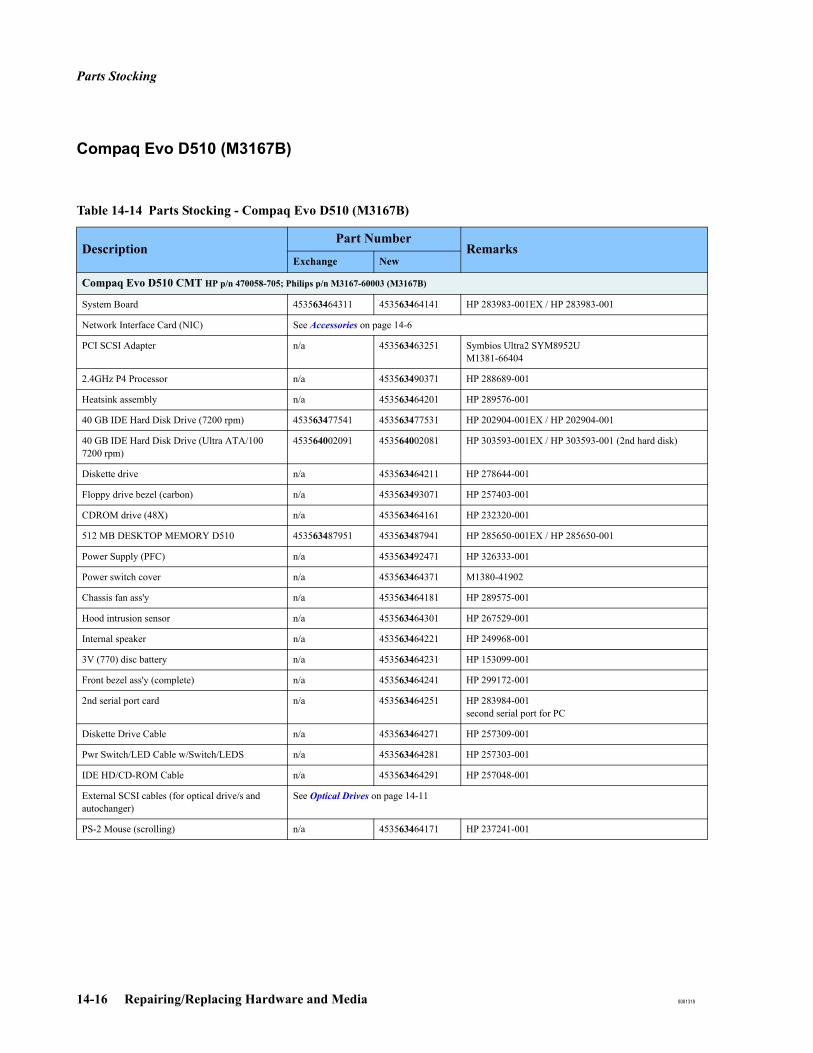
Parts Stocking
14-16 Repairing/Replacing Hardware and Media 8081318
Compaq Evo D510 (M3167B)
Table 14-14 Parts Stocking - Compaq Evo D510 (M3167B)
DescriptionPart Number
RemarksExchange New
Compaq Evo D510 CMT HP p/n 470058-705; Philips p/n M3167-60003 (M3167B)
System Board 453563464311 453563464141 HP 283983-001EX / HP 283983-001
Network Interface Card (NIC) See Accessories on page 14-6
PCI SCSI Adapter n/a 453563463251 Symbios Ultra2 SYM8952UM1381-66404
2.4GHz P4 Processor n/a 453563490371 HP 288689-001
Heatsink assembly n/a 453563464201 HP 289576-001
40 GB IDE Hard Disk Drive (7200 rpm) 453563477541 453563477531 HP 202904-001EX / HP 202904-001
40 GB IDE Hard Disk Drive (Ultra ATA/100 7200 rpm)
453564002091 453564002081 HP 303593-001EX / HP 303593-001 (2nd hard disk)
Diskette drive n/a 453563464211 HP 278644-001
Floppy drive bezel (carbon) n/a 453563493071 HP 257403-001
CDROM drive (48X) n/a 453563464161 HP 232320-001
512 MB DESKTOP MEMORY D510 453563487951 453563487941 HP 285650-001EX / HP 285650-001
Power Supply (PFC) n/a 453563492471 HP 326333-001
Power switch cover n/a 453563464371 M1380-41902
Chassis fan ass'y n/a 453563464181 HP 289575-001
Hood intrusion sensor n/a 453563464301 HP 267529-001
Internal speaker n/a 453563464221 HP 249968-001
3V (770) disc battery n/a 453563464231 HP 153099-001
Front bezel ass'y (complete) n/a 453563464241 HP 299172-001
2nd serial port card n/a 453563464251 HP 283984-001second serial port for PC
Diskette Drive Cable n/a 453563464271 HP 257309-001
Pwr Switch/LED Cable w/Switch/LEDS n/a 453563464281 HP 257303-001
IDE HD/CD-ROM Cable n/a 453563464291 HP 257048-001
External SCSI cables (for optical drive/s and autochanger)
See Optical Drives on page 14-11
PS-2 Mouse (scrolling) n/a 453563464171 HP 237241-001

Parts Stocking
8081318 Repairing/Replacing Hardware and Media 14-17
HP D530 (M3167C and M3167D)
Table 14-15 Parts Stocking - HP D530 (M3167C and M3167D)
DescriptionPart Number
RemarksExchange New
HP D530 HP p/n: DR476C #ABA; Philips p/n: M3167-60004 (M3167C)
Front bezel assembly with sub panel, 5.25" bezel 453564002231 453564002221 HP 336443-001EX / HP 336443-001
Network Interface Card (NIC) See Accessories on page 14-6
Power supply, PFC n/a 453564002241 HP 308615-001
System board with alcohol pad and thermal grease
453564002261 453564002251 HP 323091-001EX / HP 323091-001
PCI SCSI Adapter see Compaq Evo D510 (M3167B) on page 14-16
Heatsink for Pentium 4 processors n/a 453564002271 HP 333866-001
Pentium 2.66 GHz processor 453564002291 453564002281 HP 305579-001EX / HP 305579-001
256 MB/333 MHz FSB SDRAM DIMM Memory n/a 453564002311 HP 314793-001
512 MB/333 MHz FSB SDRAM DIMM Memory n/a 453564002321 HP 314796-001
40 GB IDE Hard Disk Drive (7200 rpm) 453564002341 453564002331 HP 286692-001EX / HP 286692-001 (1st hard disk)
40 GB IDE Hard Disk Drive (Ultra ATA/100 7200 rpm)
453564002091 453564002081 HP 303593-001EX / HP 303593-001 (2nd hard disk)
1.44MB, 3.5" Diskette drive with mounting screws
n/a 453564002351 HP 333505-001
48X CD-ROM drive with mounting screws n/a 453564002361 HP 326773-001
Chassis fan n/a 453564002371 HP 330457-001
IDE cable, 15.25", two device (108950-047) n/a 453564002381 HP 336448-001
Power switch/LED cable with switch holder n/a 453564002391 HP 336447-001
Diskette drive cable (143218-006) n/a 453564002401 HP 333875-001
IDE cable, 12.5", two device (108950-046) n/a 453564002411 HP 333876-001
Hood intrusion sensor n/a 453563464301 HP 267529-001
3V (770) disc battery n/a 453563464231 HP 153099-001
Power Switch Cover n/a 453564002431 M3180-40202
2nd serial port w/ribbon cable n/a 453564026211 HP 341899-001
External SCSI cables (for optical drive/s and autochanger)
See Optical Drives on page 14-11
HP D530 HP p/n: PF949UC #ABA; Philips p/n: M3167-60006 (M3167D) (common parts see M3167-60004)
2.8 GHZ Processor n/a 453564010831 HP 359573-001
80GB Hard Disk Drive n/a 453564008481 HP A276356 (for Philips)M3167-69019 (2nd hard disk)
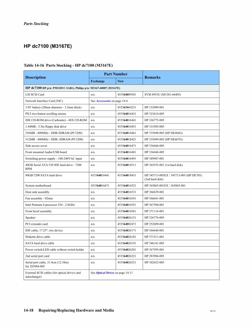
Parts Stocking
14-18 Repairing/Replacing Hardware and Media 8081318
HP dc7100 (M3167E)
Table 14-16 Parts Stocking - HP dc7100 (M3167E)
DescriptionPart Number
RemarksExchange New
HP dc7100 HP p/n: PM110UC #ABA; Philips p/n: M3167-60007 (M3167E)
LSI SCSI Card n/a 453564009301 SYM 8953U (M1381-66405)
Network Interface Card (NIC) See Accessories on page 14-6
3.0V battery (20mm diameter - 3.2mm thick) n/a 453563464231 HP 153099-001
PS/2 two-button scrolling mouse n/a 453564016431 HP 323614-005
IDE CD-ROM drive (Carbonite) - 48X CD-ROM n/a 453564016441 HP 326773-005
1.44MB - 3.5in floppy disk drive n/a 453564016451 HP 333505-005
256MB - 400MHz - DDR-SDRAM (PC3200) n/a 453564016461 HP 335698-005 (HP DE466G)
512MB - 400MHz - DDR- SDRAM (PC3200) n/a 453564018421 HP 335699-005 (HP DE467G)
Side access cover n/a 453564016471 HP 336444-005
Front mounted Audio/USB board n/a 453564016481 HP 336446-005
Switching power supply - 100-240VAC input n/a 453564016491 HP 349987-001
40GB Serial ATA/150 IDE hard drive - 7200 RPM
n/a 453564016511 HP 365555-001 (1st hard disk)
80GB\7200 SATA hard drive 453564018441 453564018431 HP 345713-005EX / 345713-005 (HP DE705) (2nd hard disk)
System motherboard 453564016671 453564016521 HP 365865-001EX / 365865-001
Heat sink assembly n/a 453564016531 HP 366639-001
Fan assembly - 92mm n/a 453564016541 HP 366641-001
Intel Pentium 4 processor 520 - 2.8GHz n/a 453564016551 HP 367594-001
Front bezel assembly n/a 453564016561 HP 371116-001
Speaker n/a 453564026151 HP 326776-005
PCI extender card n/a 453564002471 HP 252609-001
IDE cable, 17.25", two device n/a 453564026171 HP 366640-001
Diskette drive cable n/a 453564026181 HP 371511-001
SATA hard drive cable n/a 453564026191 HP 346141-005
Power switch/LED cable without switch holder n/a 453564026201 HP 367595-001
2nd serial port card n/a 453564026221 HP 283984-005
Serial port cable, 31.4cm (12.38in)for 283984-005
n/a 453564026231 HP 302652-005
External SCSI cables (for optical drive/s and autochanger)
See Optical Drives on page 14-11

Parts Stocking
8081318 Repairing/Replacing Hardware and Media 14-19
HP dc7600 (M3167F and M3167G)
Table 14-17 Parts Stocking - HP dc7600 (M3167F and M3167G)
DescriptionPart Number
RemarksExchange New
HP dc7600 HP p/n: EH618UC #ABA; Philips p/n: M3167-60009 (M3167F)
PCI SCSI card n/a 453564023991 Adaptec 29160; 1821900 (M1381-66403)
Network Interface Card (NIC) See Accessories on page 14-6
3.0V battery (20mm diameter - 3.2mm thick) n/a 453563464231 HP 153099-001
PS/2 two-button scrolling mouse n/a 453564026451 HP 390937-001
IDE CD-ROM drive (Carbonite) - 48X CD-ROM n/a 453564016441 HP 326773-005
1.44MB - 3.5in floppy disk drive n/a 453564026461 HP 392415-001
512MB - 533MHz - DDR2 SDRAM (PC4200) n/a 453564026471 HP 393393-001 (HP PV560AA)
Side access cover n/a 453564026481 HP 392405-001
Front mounted Audio/USB board n/a 453564026491 HP 392408-001
Switching power supply - 100-240VAC input n/a 453564026501 HP 381023-001
40GB Serial ATA/150 IDE hard drive - 7200 RPM
n/a 453564016511 HP 365555-001 (client, standard servers)
80GB SATA II HDD For DC7600 n/a 453564037451 391945-001 (HP PY276AA)(2nd hard disk - standard server w/storage)
System motherboard n/a 453564026511 HP 380356-001
Heat sink assembly n/a 453564026531 HP 382023-001
Chassis Fan n/a 453564026541 HP 392412-001
Intel Pentium4 3.0 GHz, 800 MHz FSB, type 531, 1MB cache
n/a 453564026551 HP 394642-001
Front bezel assembly n/a 453564016561 HP 371116-001
Speaker n/a 453564026561 HP 392413-001
Second Serial Port n/a 453564026571 HP 392414-001
IDE cable, ODD, 17.25", two device n/a 453564026581 HP 392286-001
Diskette drive cable n/a 453564026591 HP 392288-001
SATA hard drive cable, 13" n/a 453564026601 HP 391738-001
Power switch/LED cable without switch holder n/a 453564026611 HP 392285-001
External SCSI cables (for optical drive/s and autochanger)
See Optical Drives on page 14-11
HP dc7600 HP p/n: EN824UC #ABA; Philips p/n: M3167-60013 (M3167G) (common parts see M3167-60009)
Intel Pentium4 3.0 GHz, 800 MHz FSB, type 630, 2MB cache
n/a 453564038461 HP 392273-001
80GB SATA II HDD For DC7600 n/a 453564026641 391945-001 (HP PY276AA)(client, standard servers 1st and 2nd HDD)
DVD ROM 16/48X n/a 453564038451 HP 391946-001 (HP PU660AV)
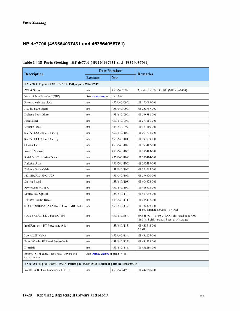
Parts Stocking
14-20 Repairing/Replacing Hardware and Media 8081318
HP dc7700 (453564037431 and 453564056761)
Table 14-18 Parts Stocking - HP dc7700 (453564037431 and 453564056761)
DescriptionPart Number
RemarksExchange New
HP dc7700 HP p/n: RR202UC #ABA; Philips p/n: 453564037431
PCI SCSI card n/a 453564023991 Adaptec 29160; 1821900 (M1381-66403)
Network Interface Card (NIC) See Accessories on page 14-6
Battery, real-time clock n/a 453564050951 HP 153099-001
5.25 in. Bezel Blank n/a 453564050961 HP 335937-005
Diskette Bezel Blank n/a 453564050971 HP 336581-005
Front Bezel n/a 453564050981 HP 371116-001
Diskette Bezel n/a 453564050991 HP 371119-001
SATA HDD Cable, 13-in. lg n/a 453564051001 HP 391738-001
SATA HDD Cable, 19-in. lg n/a 453564051011 HP 391739-001
Chassis Fan n/a 453564051021 HP 392412-001
Internal Speaker n/a 453564051031 HP 392413-001
Serial Port Expansion Device n/a 453564051041 HP 392414-001
Diskette Drive n/a 453564051051 HP 392415-001
Diskette Drive Cable n/a 453564051061 HP 395967-001
512 MB, PC2-5300, CL5 n/a 453564051071 HP 396520-001
System Board n/a 453564051081 HP 404673-001
Power Supply, 365W n/a 453564051091 HP 416535-001
Mouse, PS2 Optical n/a 453564051101 HP 417966-001
16x/48x Combo Drive n/a 453564051111 HP 419497-001
80-GB\7200RPM SATA Hard Drive, 8MB Cache n/a 453564051121 HP 432392-001(client, standard servers 1st HDD)
80GB SATA II HDD For DC7600 n/a 453564026641 391945-001 (HP PY276AA), also used in dc7700(2nd hard disk - standard server w/storage)
Intel Pentium 4 HT Processor, #915 n/a 453564051131 HP 433843-0012.8 GHz
Power/LED Cable n/a 453564051141 HP 435257-001
Front I/O with USB and Audio Cable n/a 453564051151 HP 435258-001
Heatsink n/a 453564051161 HP 435259-001
External SCSI cables (for optical drive/s and autochanger)
See Optical Drives on page 14-11
HP dc7700 HP p/n: GF894UC#ABA; Philips p/n: 453564056761 (common parts see 453564037431)
Intel® E4300 Duo Processor - 1.8GHz n/a 453564061981 HP 444050-001
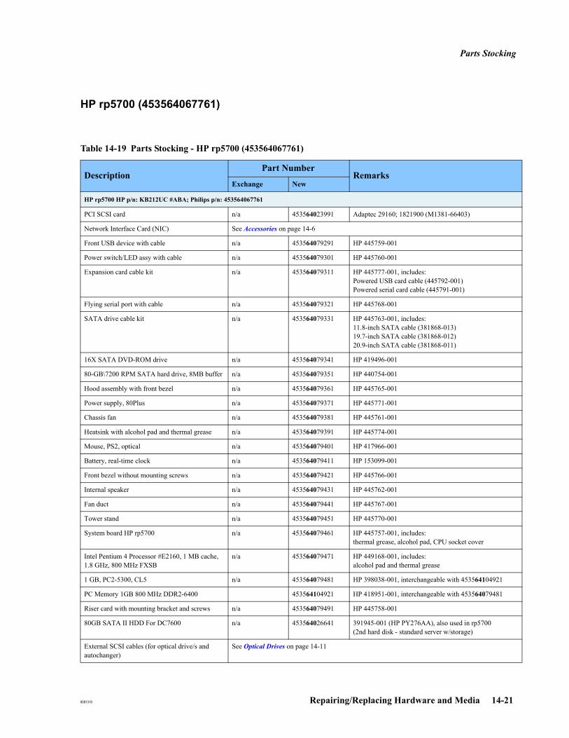
Parts Stocking
8081318 Repairing/Replacing Hardware and Media 14-21
HP rp5700 (453564067761)
Table 14-19 Parts Stocking - HP rp5700 (453564067761)
DescriptionPart Number
RemarksExchange New
HP rp5700 HP p/n: KB212UC #ABA; Philips p/n: 453564067761
PCI SCSI card n/a 453564023991 Adaptec 29160; 1821900 (M1381-66403)
Network Interface Card (NIC) See Accessories on page 14-6
Front USB device with cable n/a 453564079291 HP 445759-001
Power switch/LED assy with cable n/a 453564079301 HP 445760-001
Expansion card cable kit n/a 453564079311 HP 445777-001, includes:Powered USB card cable (445792-001)Powered serial card cable (445791-001)
Flying serial port with cable n/a 453564079321 HP 445768-001
SATA drive cable kit n/a 453564079331 HP 445763-001, includes:11.8-inch SATA cable (381868-013)19.7-inch SATA cable (381868-012)20.9-inch SATA cable (381868-011)
16X SATA DVD-ROM drive n/a 453564079341 HP 419496-001
80-GB\7200 RPM SATA hard drive, 8MB buffer n/a 453564079351 HP 440754-001
Hood assembly with front bezel n/a 453564079361 HP 445765-001
Power supply, 80Plus n/a 453564079371 HP 445771-001
Chassis fan n/a 453564079381 HP 445761-001
Heatsink with alcohol pad and thermal grease n/a 453564079391 HP 445774-001
Mouse, PS2, optical n/a 453564079401 HP 417966-001
Battery, real-time clock n/a 453564079411 HP 153099-001
Front bezel without mounting screws n/a 453564079421 HP 445766-001
Internal speaker n/a 453564079431 HP 445762-001
Fan duct n/a 453564079441 HP 445767-001
Tower stand n/a 453564079451 HP 445770-001
System board HP rp5700 n/a 453564079461 HP 445757-001, includes:thermal grease, alcohol pad, CPU socket cover
Intel Pentium 4 Processor #E2160, 1 MB cache, 1.8 GHz, 800 MHz FXSB
n/a 453564079471 HP 449168-001, includes:alcohol pad and thermal grease
1 GB, PC2-5300, CL5 n/a 453564079481 HP 398038-001, interchangeable with 453564104921
PC Memory 1GB 800 MHz DDR2-6400 453564104921 HP 418951-001, interchangeable with 453564079481
Riser card with mounting bracket and screws n/a 453564079491 HP 445758-001
80GB SATA II HDD For DC7600 n/a 453564026641 391945-001 (HP PY276AA), also used in rp5700(2nd hard disk - standard server w/storage)
External SCSI cables (for optical drive/s and autochanger)
See Optical Drives on page 14-11
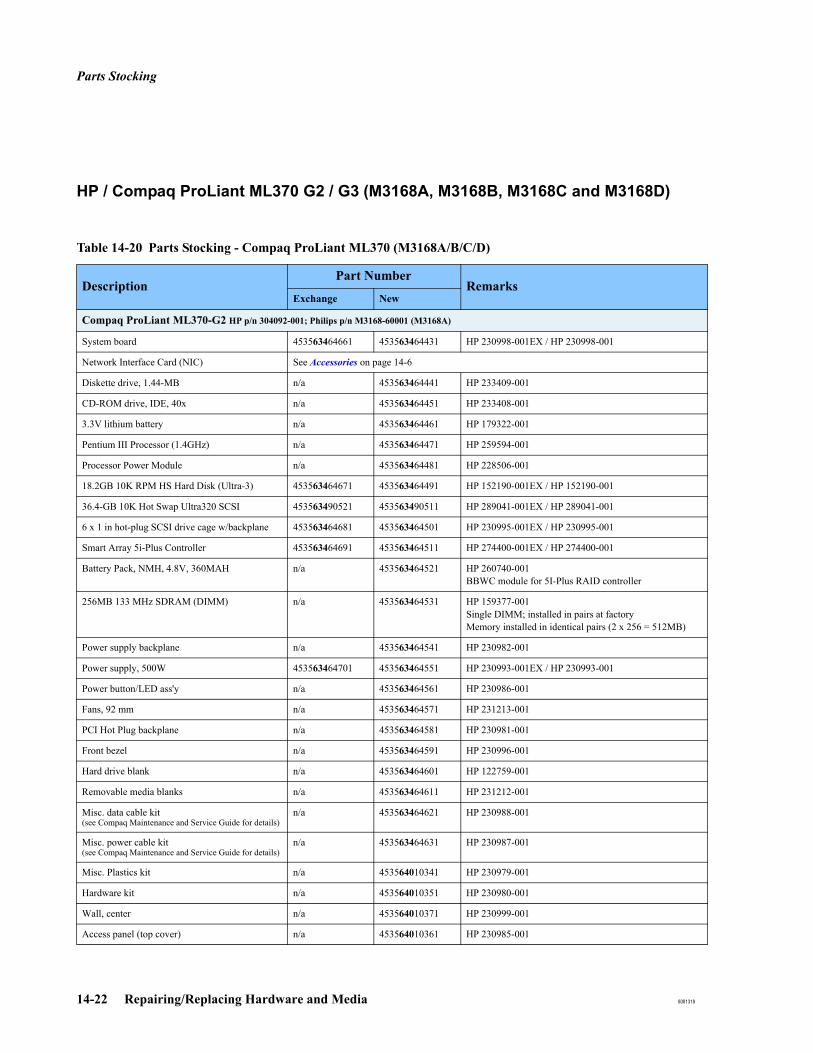
Parts Stocking
14-22 Repairing/Replacing Hardware and Media 8081318
HP / Compaq ProLiant ML370 G2 / G3 (M3168A, M3168B, M3168C and M3168D)
Table 14-20 Parts Stocking - Compaq ProLiant ML370 (M3168A/B/C/D)
DescriptionPart Number
RemarksExchange New
Compaq ProLiant ML370-G2 HP p/n 304092-001; Philips p/n M3168-60001 (M3168A)
System board 453563464661 453563464431 HP 230998-001EX / HP 230998-001
Network Interface Card (NIC) See Accessories on page 14-6
Diskette drive, 1.44-MB n/a 453563464441 HP 233409-001
CD-ROM drive, IDE, 40x n/a 453563464451 HP 233408-001
3.3V lithium battery n/a 453563464461 HP 179322-001
Pentium III Processor (1.4GHz) n/a 453563464471 HP 259594-001
Processor Power Module n/a 453563464481 HP 228506-001
18.2GB 10K RPM HS Hard Disk (Ultra-3) 453563464671 453563464491 HP 152190-001EX / HP 152190-001
36.4-GB 10K Hot Swap Ultra320 SCSI 453563490521 453563490511 HP 289041-001EX / HP 289041-001
6 x 1 in hot-plug SCSI drive cage w/backplane 453563464681 453563464501 HP 230995-001EX / HP 230995-001
Smart Array 5i-Plus Controller 453563464691 453563464511 HP 274400-001EX / HP 274400-001
Battery Pack, NMH, 4.8V, 360MAH n/a 453563464521 HP 260740-001BBWC module for 5I-Plus RAID controller
256MB 133 MHz SDRAM (DIMM) n/a 453563464531 HP 159377-001Single DIMM; installed in pairs at factoryMemory installed in identical pairs (2 x 256 = 512MB)
Power supply backplane n/a 453563464541 HP 230982-001
Power supply, 500W 453563464701 453563464551 HP 230993-001EX / HP 230993-001
Power button/LED ass'y n/a 453563464561 HP 230986-001
Fans, 92 mm n/a 453563464571 HP 231213-001
PCI Hot Plug backplane n/a 453563464581 HP 230981-001
Front bezel n/a 453563464591 HP 230996-001
Hard drive blank n/a 453563464601 HP 122759-001
Removable media blanks n/a 453563464611 HP 231212-001
Misc. data cable kit(see Compaq Maintenance and Service Guide for details)
n/a 453563464621 HP 230988-001
Misc. power cable kit(see Compaq Maintenance and Service Guide for details)
n/a 453563464631 HP 230987-001
Misc. Plastics kit n/a 453564010341 HP 230979-001
Hardware kit n/a 453564010351 HP 230980-001
Wall, center n/a 453564010371 HP 230999-001
Access panel (top cover) n/a 453564010361 HP 230985-001

Parts Stocking
8081318 Repairing/Replacing Hardware and Media 14-23
Tower hood cover n/a 453564010381 HP 233410-001
2 button mouse n/a 453563464641 HP 113907-001
External SCSI cables (for optical drive/s and autochanger)
See Optical Drives on page 14-11
HP ProLiant ML370-G3 HP p/n: 341419-001; Philips p/n: M3168-60002 (M3168B) (common parts see M3168-60001)
36.4-GB 10K Hot Swap Ultra320 SCSI 453563490521 453563490511 HP 289041-001EX / HP 289041-001
SCSI Backplane w/6 x 1-inch drive cage n/a 453563494591 HP 262171-001
CD-ROM drive - IDE - 48X n/a 453563494601 HP 288894-001
Processor power module (PPM) n/a 453563494611 HP 289564-001
Intel Xeon 2.4-GHz proc w/heatsink 453563494631 453563494621 HP 290558-001EX / HP 290558-001
System board with proc cage 453563494651 453563494641 HP 290559-001EX / HP 290559-001
Miscellaneous data cable kit n/a 453563494661 HP 292229-001
256-MB DDR DIMM PC2100 - 1.2-in 453563494681 453563494671 HP 300699-001EX / HP 300699-001Single DIMM; installed in pairs at factory
Smart Array 641 Controller 453563494701 453563494691 HP 305414-001EX / HP 305414-001
64MB battery backed write cache (BBWC) n/a 453563494711 HP 305416-001 (includes battery; Mem -DDR -40bit w/Battery)
3.6-V battery pack - 500mAH (NiMH) n/a 453564025451 HP 307132-001 (for BBWC module)
Hard drive blank n/a 453564010391 HP 313046-001
Mouse - CB n/a 453563494721 HP 311060-001
HP ProLiant ML370-G3 HP p/n: 351371-001; Philips p/n: M3168-60003 (M3168C) (common parts see M3168-60002)
Intel Xeon 2.8-GHz proc w/heatsink 453564001191 453564001181 HP 307103-001EX / HP 307103-001
HP ProLiant ML370-G3 HP p/n: 371920-001; Philips p/n: M3168-60004 (M3168D) (common parts see M3168-60002)
Processor, Intel Xeon 3.06-GHz 453564006591 453564005531 HP 314669-001EX / HP 314669-001
72.8-GB HS Ultra 320 SCSI HDD - New n/a 453564010331 HP 289042-001 (for ref only: M3168-69019)
PC2100 - 512MB - DDR DIMM(ML370) 453564003261 453563495491 HP 300700-001EX / HP 300700-001Single DIMM; installed in pairs at factory
1-GB PC2100 DDR Memory n/a 453564008451 HP 300701-001Single DIMM; installed in pairs at factory
Front bezel (tower model only) n/a 453564010421 HP 319600-001
System board w/proc cage 453564010411 453564010401 HP 316864-001EX / 316864-001
Table 14-20 Parts Stocking - Compaq ProLiant ML370 (M3168A/B/C/D)
DescriptionPart Number
RemarksExchange New
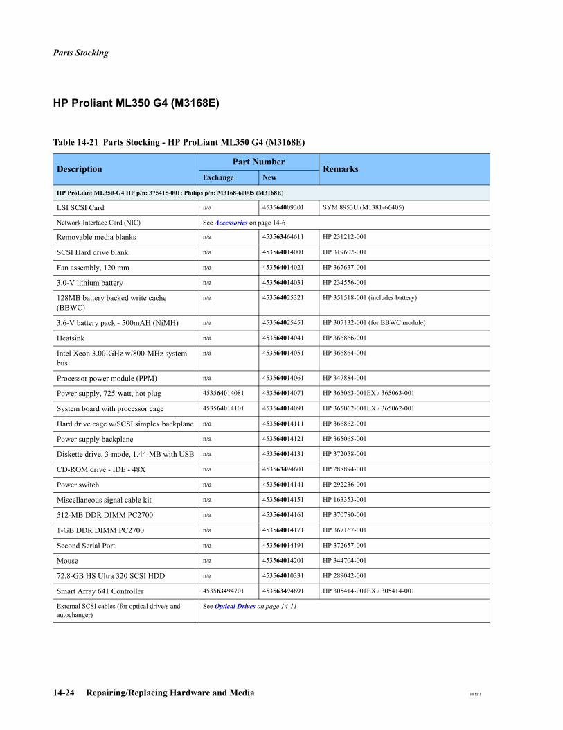
Parts Stocking
14-24 Repairing/Replacing Hardware and Media 8081318
HP Proliant ML350 G4 (M3168E)
Table 14-21 Parts Stocking - HP ProLiant ML350 G4 (M3168E)
DescriptionPart Number
RemarksExchange New
HP ProLiant ML350-G4 HP p/n: 375415-001; Philips p/n: M3168-60005 (M3168E)
LSI SCSI Card n/a 453564009301 SYM 8953U (M1381-66405)
Network Interface Card (NIC) See Accessories on page 14-6
Removable media blanks n/a 453563464611 HP 231212-001
SCSI Hard drive blank n/a 453564014001 HP 319602-001
Fan assembly, 120 mm n/a 453564014021 HP 367637-001
3.0-V lithium battery n/a 453564014031 HP 234556-001
128MB battery backed write cache (BBWC)
n/a 453564025321 HP 351518-001 (includes battery)
3.6-V battery pack - 500mAH (NiMH) n/a 453564025451 HP 307132-001 (for BBWC module)
Heatsink n/a 453564014041 HP 366866-001
Intel Xeon 3.00-GHz w/800-MHz system bus
n/a 453564014051 HP 366864-001
Processor power module (PPM) n/a 453564014061 HP 347884-001
Power supply, 725-watt, hot plug 453564014081 453564014071 HP 365063-001EX / 365063-001
System board with processor cage 453564014101 453564014091 HP 365062-001EX / 365062-001
Hard drive cage w/SCSI simplex backplane n/a 453564014111 HP 366862-001
Power supply backplane n/a 453564014121 HP 365065-001
Diskette drive, 3-mode, 1.44-MB with USB n/a 453564014131 HP 372058-001
CD-ROM drive - IDE - 48X n/a 453563494601 HP 288894-001
Power switch n/a 453564014141 HP 292236-001
Miscellaneous signal cable kit n/a 453564014151 HP 163353-001
512-MB DDR DIMM PC2700 n/a 453564014161 HP 370780-001
1-GB DDR DIMM PC2700 n/a 453564014171 HP 367167-001
Second Serial Port n/a 453564014191 HP 372657-001
Mouse n/a 453564014201 HP 344704-001
72.8-GB HS Ultra 320 SCSI HDD n/a 453564010331 HP 289042-001
Smart Array 641 Controller 453563494701 453563494691 HP 305414-001EX / 305414-001
External SCSI cables (for optical drive/s and autochanger)
See Optical Drives on page 14-11
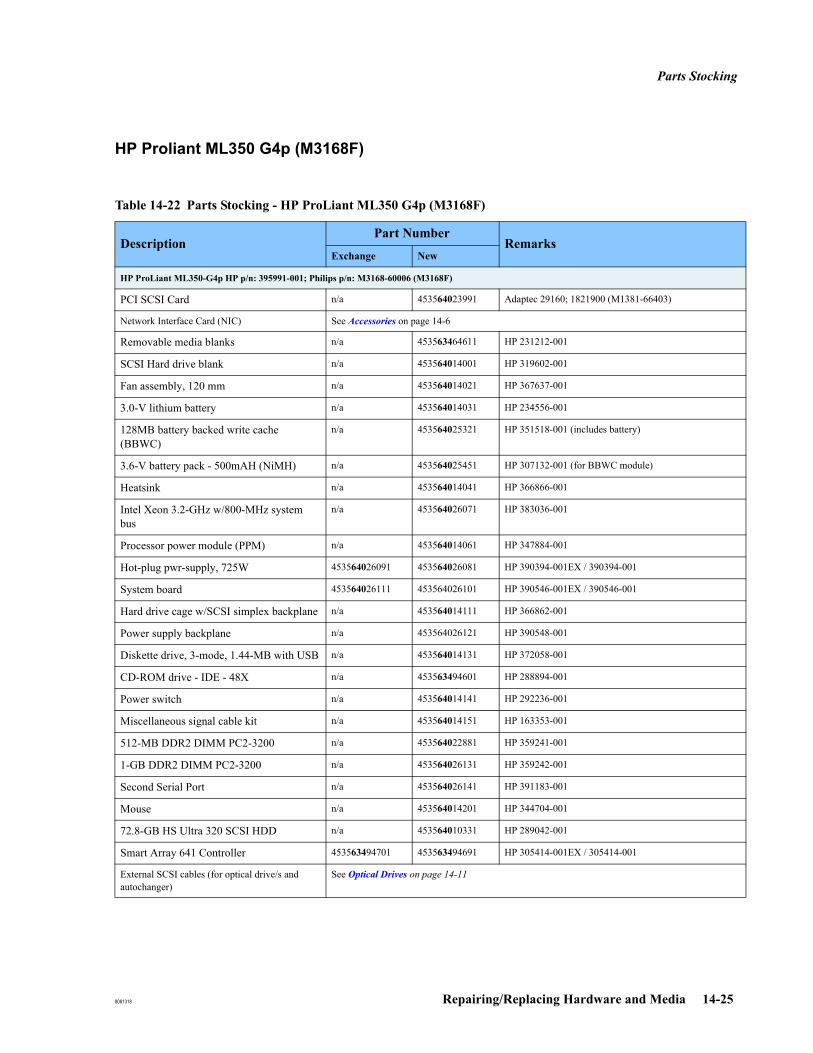
Parts Stocking
8081318 Repairing/Replacing Hardware and Media 14-25
HP Proliant ML350 G4p (M3168F)
Table 14-22 Parts Stocking - HP ProLiant ML350 G4p (M3168F)
DescriptionPart Number
RemarksExchange New
HP ProLiant ML350-G4p HP p/n: 395991-001; Philips p/n: M3168-60006 (M3168F)
PCI SCSI Card n/a 453564023991 Adaptec 29160; 1821900 (M1381-66403)
Network Interface Card (NIC) See Accessories on page 14-6
Removable media blanks n/a 453563464611 HP 231212-001
SCSI Hard drive blank n/a 453564014001 HP 319602-001
Fan assembly, 120 mm n/a 453564014021 HP 367637-001
3.0-V lithium battery n/a 453564014031 HP 234556-001
128MB battery backed write cache (BBWC)
n/a 453564025321 HP 351518-001 (includes battery)
3.6-V battery pack - 500mAH (NiMH) n/a 453564025451 HP 307132-001 (for BBWC module)
Heatsink n/a 453564014041 HP 366866-001
Intel Xeon 3.2-GHz w/800-MHz system bus
n/a 453564026071 HP 383036-001
Processor power module (PPM) n/a 453564014061 HP 347884-001
Hot-plug pwr-supply, 725W 453564026091 453564026081 HP 390394-001EX / 390394-001
System board 453564026111 453564026101 HP 390546-001EX / 390546-001
Hard drive cage w/SCSI simplex backplane n/a 453564014111 HP 366862-001
Power supply backplane n/a 453564026121 HP 390548-001
Diskette drive, 3-mode, 1.44-MB with USB n/a 453564014131 HP 372058-001
CD-ROM drive - IDE - 48X n/a 453563494601 HP 288894-001
Power switch n/a 453564014141 HP 292236-001
Miscellaneous signal cable kit n/a 453564014151 HP 163353-001
512-MB DDR2 DIMM PC2-3200 n/a 453564022881 HP 359241-001
1-GB DDR2 DIMM PC2-3200 n/a 453564026131 HP 359242-001
Second Serial Port n/a 453564026141 HP 391183-001
Mouse n/a 453564014201 HP 344704-001
72.8-GB HS Ultra 320 SCSI HDD n/a 453564010331 HP 289042-001
Smart Array 641 Controller 453563494701 453563494691 HP 305414-001EX / 305414-001
External SCSI cables (for optical drive/s and autochanger)
See Optical Drives on page 14-11
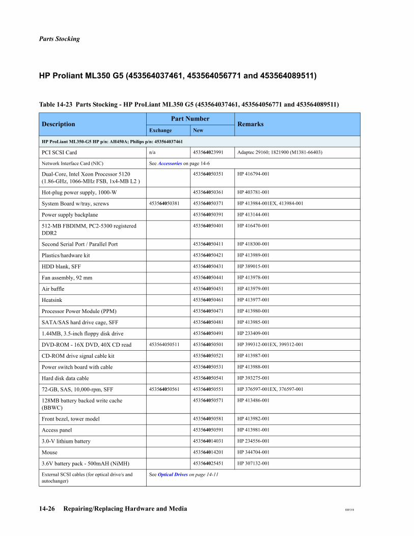
Parts Stocking
14-26 Repairing/Replacing Hardware and Media 8081318
HP Proliant ML350 G5 (453564037461, 453564056771 and 453564089511)
Table 14-23 Parts Stocking - HP ProLiant ML350 G5 (453564037461, 453564056771 and 453564089511)
DescriptionPart Number
RemarksExchange New
HP ProLiant ML350-G5 HP p/n: AH450A; Philips p/n: 453564037461
PCI SCSI Card n/a 453564023991 Adaptec 29160; 1821900 (M1381-66403)
Network Interface Card (NIC) See Accessories on page 14-6
Dual-Core, Intel Xeon Processor 5120 (1.86-GHz, 1066-MHz FSB, 1x4-MB L2 )
453564050351 HP 416794-001
Hot-plug power supply, 1000-W 453564050361 HP 403781-001
System Board w/tray, screws 453564050381 453564050371 HP 413984-001EX, 413984-001
Power supply backplane 453564050391 HP 413144-001
512-MB FBDIMM, PC2-5300 registered DDR2
453564050401 HP 416470-001
Second Serial Port / Parallel Port 453564050411 HP 418300-001
Plastics/hardware kit 453564050421 HP 413989-001
HDD blank, SFF 453564050431 HP 389015-001
Fan assembly, 92 mm 453564050441 HP 413978-001
Air baffle 453564050451 HP 413979-001
Heatsink 453564050461 HP 413977-001
Processor Power Module (PPM) 453564050471 HP 413980-001
SATA/SAS hard drive cage, SFF 453564050481 HP 413985-001
1.44MB, 3.5-inch floppy disk drive 453564050491 HP 233409-001
DVD-ROM - 16X DVD, 40X CD read 453564050511 453564050501 HP 399312-001EX, 399312-001
CD-ROM drive signal cable kit 453564050521 HP 413987-001
Power switch board with cable 453564050531 HP 413988-001
Hard disk data cable 453564050541 HP 393275-001
72-GB, SAS, 10,000-rpm, SFF 453564050561 453564050551 HP 376597-001EX, 376597-001
128MB battery backed write cache (BBWC)
453564050571 HP 413486-001
Front bezel, tower model 453564050581 HP 413982-001
Access panel 453564050591 HP 413981-001
3.0-V lithium battery 453564014031 HP 234556-001
Mouse 453564014201 HP 344704-001
3.6V battery pack - 500mAH (NiMH) 453564025451 HP 307132-001
External SCSI cables (for optical drive/s and autochanger)
See Optical Drives on page 14-11
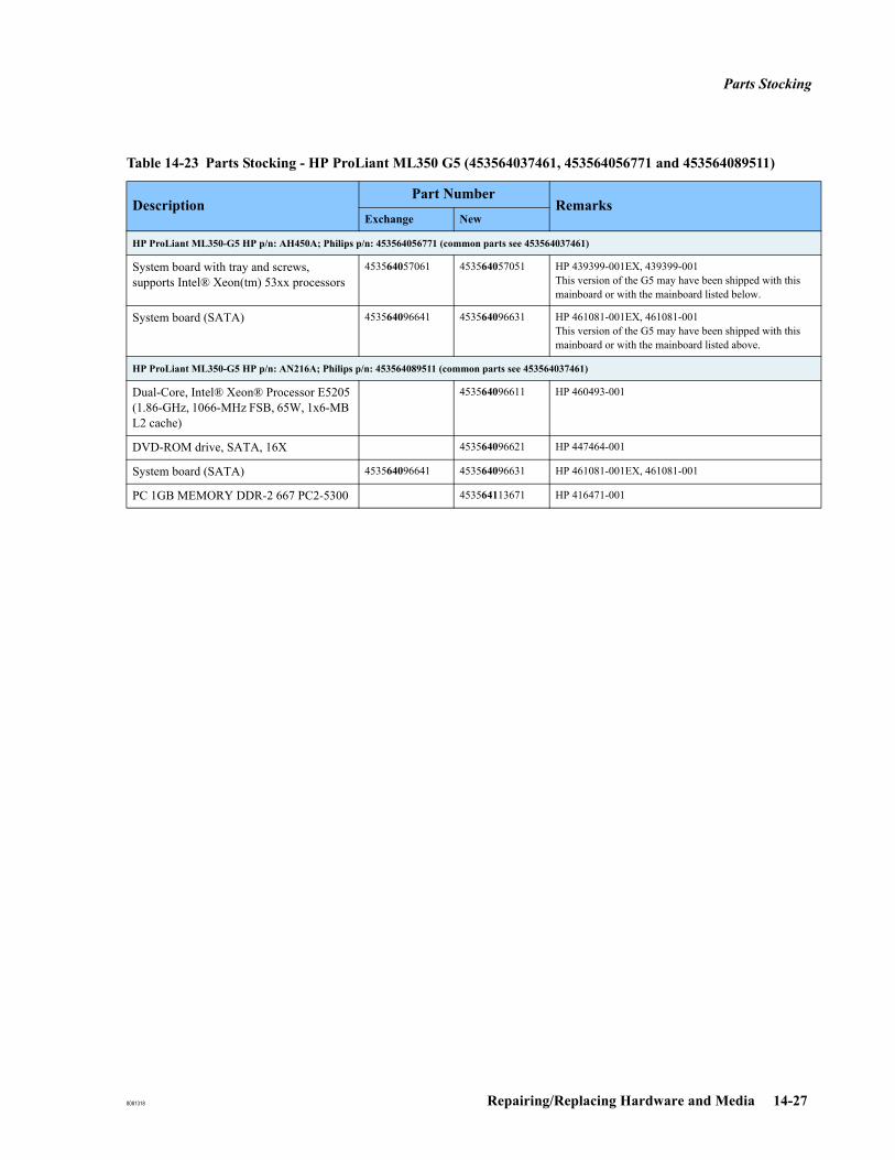
Parts Stocking
8081318 Repairing/Replacing Hardware and Media 14-27
HP ProLiant ML350-G5 HP p/n: AH450A; Philips p/n: 453564056771 (common parts see 453564037461)
System board with tray and screws, supports Intel® Xeon(tm) 53xx processors
453564057061 453564057051 HP 439399-001EX, 439399-001This version of the G5 may have been shipped with this mainboard or with the mainboard listed below.
System board (SATA) 453564096641 453564096631 HP 461081-001EX, 461081-001This version of the G5 may have been shipped with this mainboard or with the mainboard listed above.
HP ProLiant ML350-G5 HP p/n: AN216A; Philips p/n: 453564089511 (common parts see 453564037461)
Dual-Core, Intel® Xeon® Processor E5205(1.86-GHz, 1066-MHz FSB, 65W, 1x6-MB L2 cache)
453564096611 HP 460493-001
DVD-ROM drive, SATA, 16X 453564096621 HP 447464-001
System board (SATA) 453564096641 453564096631 HP 461081-001EX, 461081-001
PC 1GB MEMORY DDR-2 667 PC2-5300 453564113671 HP 416471-001
Table 14-23 Parts Stocking - HP ProLiant ML350 G5 (453564037461, 453564056771 and 453564089511)
DescriptionPart Number
RemarksExchange New
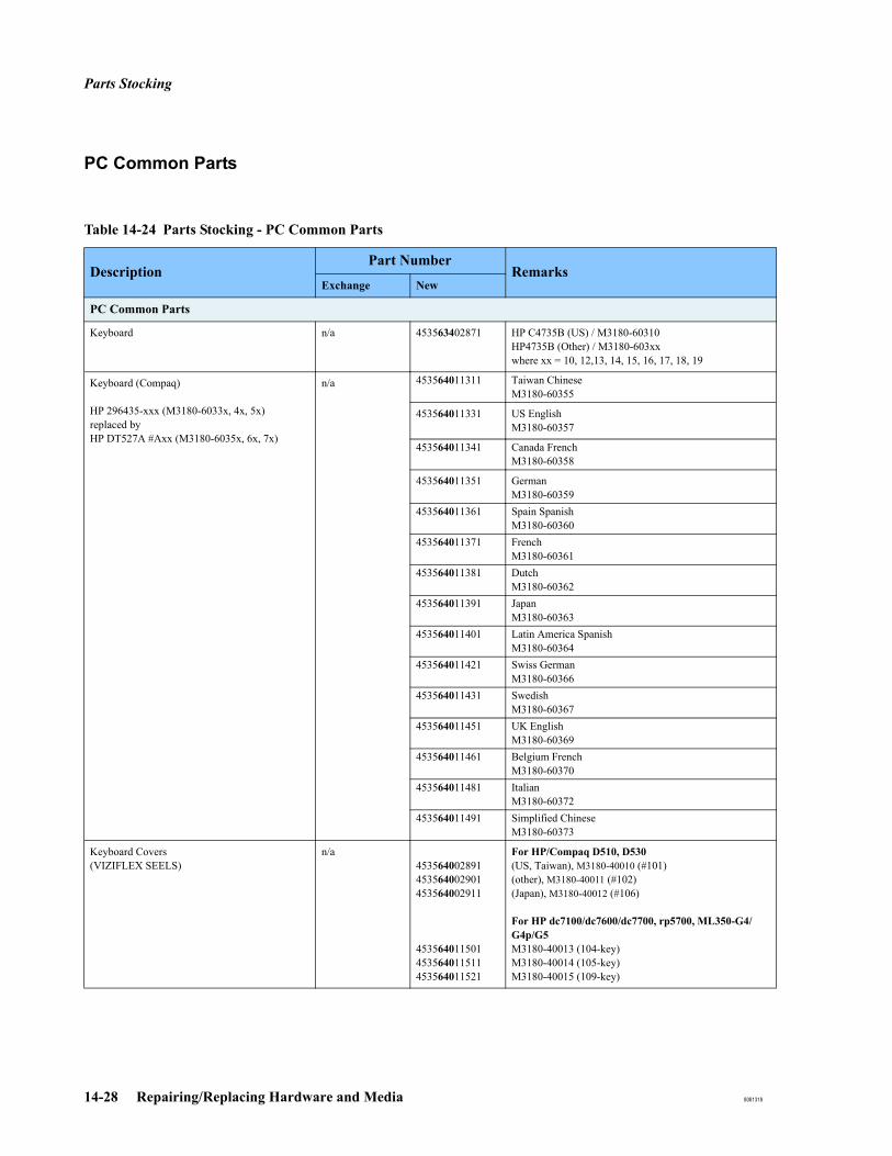
Parts Stocking
14-28 Repairing/Replacing Hardware and Media 8081318
PC Common Parts
Table 14-24 Parts Stocking - PC Common Parts
DescriptionPart Number
RemarksExchange New
PC Common Parts
Keyboard n/a 453563402871 HP C4735B (US) / M3180-60310HP4735B (Other) / M3180-603xxwhere xx = 10, 12,13, 14, 15, 16, 17, 18, 19
Keyboard (Compaq)
HP 296435-xxx (M3180-6033x, 4x, 5x)replaced byHP DT527A #Axx (M3180-6035x, 6x, 7x)
n/a 453564011311 Taiwan Chinese M3180-60355
453564011331 US English M3180-60357
453564011341 Canada French M3180-60358
453564011351 German M3180-60359
453564011361 Spain Spanish M3180-60360
453564011371 FrenchM3180-60361
453564011381 DutchM3180-60362
453564011391 JapanM3180-60363
453564011401 Latin America SpanishM3180-60364
453564011421 Swiss GermanM3180-60366
453564011431 SwedishM3180-60367
453564011451 UK EnglishM3180-60369
453564011461 Belgium FrenchM3180-60370
453564011481 ItalianM3180-60372
453564011491 Simplified ChineseM3180-60373
Keyboard Covers(VIZIFLEX SEELS)
n/a453564002891453564002901453564002911
453564011501453564011511453564011521
For HP/Compaq D510, D530(US, Taiwan), M3180-40010 (#101)(other), M3180-40011 (#102)(Japan), M3180-40012 (#106)
For HP dc7100/dc7600/dc7700, rp5700, ML350-G4/G4p/G5M3180-40013 (104-key)M3180-40014 (105-key)M3180-40015 (109-key)
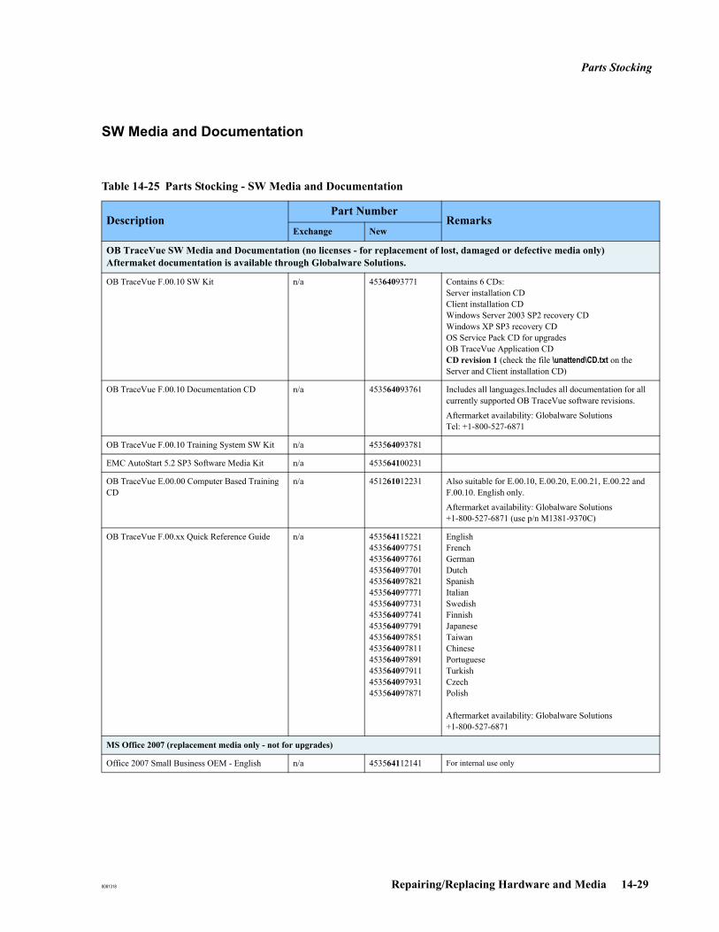
Parts Stocking
8081318 Repairing/Replacing Hardware and Media 14-29
SW Media and Documentation
Table 14-25 Parts Stocking - SW Media and Documentation
DescriptionPart Number
RemarksExchange New
OB TraceVue SW Media and Documentation (no licenses - for replacement of lost, damaged or defective media only)Aftermaket documentation is available through Globalware Solutions.
OB TraceVue F.00.10 SW Kit n/a 45364093771 Contains 6 CDs:Server installation CDClient installation CDWindows Server 2003 SP2 recovery CDWindows XP SP3 recovery CDOS Service Pack CD for upgradesOB TraceVue Application CDCD revision 1 (check the file \unattend\CD.txt on the Server and Client installation CD)
OB TraceVue F.00.10 Documentation CD n/a 453564093761 Includes all languages.Includes all documentation for all currently supported OB TraceVue software revisions.
Aftermarket availability: Globalware Solutions Tel: +1-800-527-6871
OB TraceVue F.00.10 Training System SW Kit n/a 453564093781
EMC AutoStart 5.2 SP3 Software Media Kit n/a 453564100231
OB TraceVue E.00.00 Computer Based Training CD
n/a 451261012231 Also suitable for E.00.10, E.00.20, E.00.21, E.00.22 and F.00.10. English only.
Aftermarket availability: Globalware Solutions+1-800-527-6871 (use p/n M1381-9370C)
OB TraceVue F.00.xx Quick Reference Guide n/a 453564115221453564097751453564097761453564097701453564097821453564097771453564097731453564097741453564097791453564097851453564097811453564097891453564097911453564097931453564097871
EnglishFrenchGermanDutchSpanishItalianSwedishFinnishJapaneseTaiwanChinesePortugueseTurkishCzechPolish
Aftermarket availability: Globalware Solutions+1-800-527-6871
MS Office 2007 (replacement media only - not for upgrades)
Office 2007 Small Business OEM - English n/a 453564112141 For internal use only

Parts Stocking
14-30 Repairing/Replacing Hardware and Media 8081318
UPS Parts
Table 14-26 Parts Stocking - UPS Parts
US1
1. Other geographies may also use the UPS. Internal factory rules determine what ships to a particular geography.
Europe, AP1 Japan1
Standard (networked) Internal Server
Highend Servers (All)(mandatory RS-232 cable connection)
Smart-UPS 1000SUA1000 (120V)Repl. UPS p/n: M3882-60001453563403801
Battery:RBC6-APC (453563356571)
Cable:M3180-60194 (453563336981)APC p/n 940-0024C
Smart-UPS 1000ISUA1000I (230V)Repl. UPS p/n: M3883-60001453563378591
Battery: RBC6-APC (453563356571)
Cable:M3180-60194 (453563336981)APC p/n 940-0024C
Smart-UPS 1000J SUA1000J (120V)Repl. UPS p/n: M3884-60001453563498211
Battery:RBC6-APC (453563356571)
Cable:M3180-60194 (453563336981)APC p/n 940-0024C
Standalone Internal Server
Standard External Server
Standard WEB/Ter-minal Server
Clients(optional RS-232 cable connection)
Smart-UPS 620SC620 (120V)Repl. UPS p/n: M3156-60014(453564017071)
Battery:RBC4-APC (453563356561)
Cable:M3180-60194 (453563336981)APC p/n 940-0024C
Smart-UPS 620SC620I (230V)Repl. UPS p/n: M3158-60016(453564017081)
Battery:RBC4-APC (453563356561)
Cable:M3180-60194 (453563336981)APC p/n 940-0024C
Smart-UPS 1000JSUA1000J (120V)Repl. UPS p/n: M3884-60001(453563498211)
Battery:RBC6-APC (453563356571)
Cable:M3180-60194 (453563336981)APC p/n 940-0024C
8081318 Renaming a PC 15-1
15Renaming a PC
Changing a Server PC Name1. Shutdown OB TraceVue.
2. In the Windows operating system, change the name of the PC.
You can enter the complete PC serial number (FRXXXXXXXX) as the PC name.
3. Reboot the PC.
4. On the server PC, run OB TraceVue setup (see OB TraceVue Setup on page 18-2) and accept using the new PC name.
5. Run OB TraceVue setup on all client PCs
a. Select Only change database settings or system settings.
b. Settings for this PC: Uncheck all check boxes in order to not change any settings.
c. Specify the new Server PC Name.
Changing a Client PC Name
Note If you have changed the server PC name you must complete all steps given above (including 5. Run OB TraceVue setup on all client PCs) before you rename a client PC.
1. Shutdown the OB TraceVue client PC.
2. In the Windows operating system, change the name of the PC.
You can enter the complete PC serial number (FRXXXXXXXX) as the PC name.
3. Reboot the PC.
4. Run OB TraceVue setup on the client PC and accept using the new PC name.
Replacement ClientClient PCs may be interchanged to substitute temporarily for a defective PC. If you rename a spare client PC, in order to use it as a substitute PC on the network, please see Substituting a PC on page 12-3.

Replacement Client
15-2 Renaming a PC 8081318
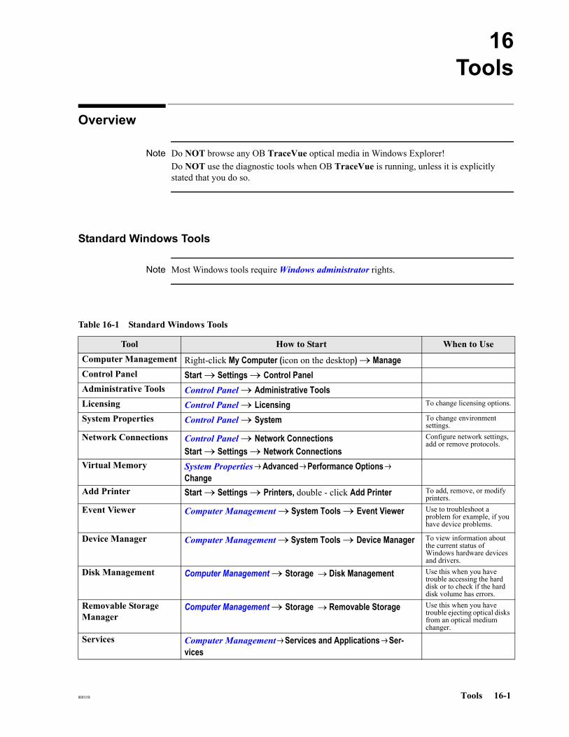
8081318 Tools 16-1
16Tools
Overview
Note Do NOT browse any OB TraceVue optical media in Windows Explorer! Do NOT use the diagnostic tools when OB TraceVue is running, unless it is explicitly stated that you do so.
Standard Windows Tools
Note Most Windows tools require Windows administrator rights.
Table 16-1 Standard Windows Tools
Tool How to Start When to UseComputer Management Right-click My Computer (icon on the desktop) → Manage Control Panel Start → Settings → Control PanelAdministrative Tools Control Panel → Administrative ToolsLicensing Control Panel → Licensing To change licensing options.
System Properties Control Panel → System To change environment settings.
Network Connections Control Panel → Network ConnectionsStart → Settings → Network Connections
Configure network settings, add or remove protocols.
Virtual Memory System Properties → Advanced → Performance Options → Change
Add Printer Start → Settings → Printers, double - click Add Printer To add, remove, or modify printers.
Event Viewer Computer Management → System Tools → Event Viewer Use to troubleshoot a problem for example, if you have device problems.
Device Manager Computer Management → System Tools → Device Manager To view information about the current status of Windows hardware devices and drivers.
Disk Management Computer Management → Storage → Disk Management Use this when you have trouble accessing the hard disk or to check if the hard disk volume has errors.
Removable Storage Manager
Computer Management → Storage → Removable Storage Use this when you have trouble ejecting optical disks from an optical medium changer.
Services Computer Management → Services and Applications → Ser-vices
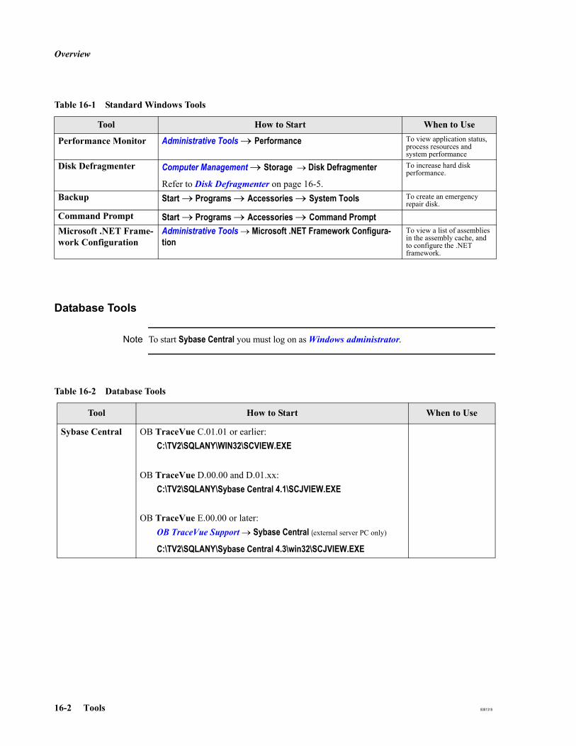
Overview
16-2 Tools 8081318
Database Tools
Note To start Sybase Central you must log on as Windows administrator.
Performance Monitor Administrative Tools → Performance To view application status, process resources and system performance
Disk Defragmenter Computer Management → Storage → Disk Defragmenter
Refer to Disk Defragmenter on page 16-5.
To increase hard disk performance.
Backup Start → Programs → Accessories → System Tools To create an emergency repair disk.
Command Prompt Start → Programs → Accessories → Command PromptMicrosoft .NET Frame-work Configuration
Administrative Tools → Microsoft .NET Framework Configura-tion
To view a list of assemblies in the assembly cache, and to configure the .NET framework.
Table 16-1 Standard Windows Tools
Tool How to Start When to Use
Table 16-2 Database Tools
Tool How to Start When to Use
Sybase Central OB TraceVue C.01.01 or earlier:C:\TV2\SQLANY\WIN32\SCVIEW.EXE
OB TraceVue D.00.00 and D.01.xx:C:\TV2\SQLANY\Sybase Central 4.1\SCJVIEW.EXE
OB TraceVue E.00.00 or later:OB TraceVue Support → Sybase Central (external server PC only)
C:\TV2\SQLANY\Sybase Central 4.3\win32\SCJVIEW.EXE

Overview
8081318 Tools 16-3
OB TraceVue Tools
Note Some tools require Windows administrator rights. In addition some of the tools require an OB TraceVue user account with special access rights. See Tools on page 3-6 for details.
Program Group Most tools are available in the OB TraceVue support program group:Start → Programs → OB TraceVue Support
Table 16-3 OB TraceVue Tools
Tool How to Start / Refer to When to Use
Administration Tool
(Patient Data Administra-tion Tool)
OB TraceVue Support → Administration Tool
Patient Data Administration Tool on page 16-6.
Note: Data administration functionality has been moved to other parts of OB TraceVue. See Other Patient Data Administration Functionality on page 16-7
After a training session, to delete “practice patients”.To delete data for patients which you do not expect to have any more episodes at the hospital. For example: patient has moved away, patient has died.
Configuration Backup Tool
OB TraceVue Support → Configuration BackupConfiguration Backup (Internal Server Only) on page 17-20
Backup: After finishing a user configuration, so that you can recover in case the configuration gets lost. Always do a backup after a software upgrade or after applying a service pack.
Reload: Directly after OB TraceVue software is reinstalled.
Database Rebuild Tool OB TraceVue Support → Database Rebuild Tool
Database Rebuild Tool on page 16-9
To optimize the database data organization.
External Database Administration Tool
OB TraceVue Support → Export Database Administration Tool
See the External Database Guide.
To purge patient data from the external database in order to reduce its size.
Fetal Monitor Spy (FMSpy)
OB TraceVue Support → SpyFetal Monitor Spy (FMSpy) on page 16-23
When you first set up a system to check that you have the correct cabling and connections to all fetal monitors.
This works for fetal monitors connected via RS232 (“Classic”) only, not for LAN-based (“Network”) monitors.

Overview
16-4 Tools 8081318
GetLog OB TraceVue Support→ Get LogGetLog on page 16-27
When the response center has requested all the system information available on an OB TraceVue system.
NetTest NetTest on page 16-28 Network analysisLogfile Viewer for OB TraceVue Error Logs
OB TraceVue Support → Logfile ViewerLogFile Viewer for OB TraceVue Error Logs on page 16-17
When the system or PC hangs.After re-start for problem diagnosis.If you have problems starting the PC. Whenever the system messages indicate any error situation.If the archive is not working properly.
Backup Tool OB TraceVue Support → Backup ToolBackup Tool on page 16-11
Online, and offline, backup
Regular backup.Backup before repair.Backup before upgrade.Backup if exchanging hardware.Backup TV2_Templates directory.Restore.Validation
System Overview Tool OB TraceVue Support → System Overview Tool
System Overview Tool on page 11-2
To check the status of OB TraceVue PCs.To reboot selected PCs or the complete OB TraceVue system.To start OB TraceVue on selected PCs or to start the complete OB TraceVue system.
Update Document Tem-plates
OB TraceVue Support → Update Document Templates
To update document templates.
SQL Editor for Office Templates
\\<Server>\OBTVTemplates\code\SQLedit.xls To edit Word Report form fields and statistic queries.
Link Recovery Tool OB TraceVue Support → Link Recovery Tool
Link Recovery Tool on page 17-18
To identify and repair inconsistent patient records on linked OB TraceVue systems.
Update Archive Tool Run c:\tv2\prog\UpdateArchive.exe
Update Archive Tool on page 16-8
As final step after upgrading.As a preparation step when planning a System Merge.Before moving an archive as part of a System Merge.
Active Directory Test Tool
Active Directory Test Tool on page 16-30 To test an existing domain user integration.To check if an upcoming integration will work.
Table 16-3 OB TraceVue Tools
Tool How to Start / Refer to When to Use

Windows Tools
8081318 Tools 16-5
Windows Tools
Disk Defragmenter
Defragmentation increases hard disk performance and therefore reduces overall OB TraceVue response times.
Defragmentation can be performed after upgrade, re-installation or on a regular basis for system maintenance.
Note Only defragment hard disks of OB TraceVue Internal Server and External Server PCs.
Process 1. Stop OB TraceVue.
2. Log in as a Windows user having administrator rights.
3. Depending on which server you are defragmenting:
On the External server, stop the OB TraceVue database server service using Sybase Central on page 16-2.
On the internal server, stop NetMsg Service (which stops the database service). OB TraceVue:
Select MyComputer → Manage → Services and Applications → Services → NetMsgService → Stop.
4. Start the Disk Defragmenter on page 16-5.
5. Select the disk to be defragmented.
Caution: Never defragment an optical disk.
6. Click the Defragment button.
7. Defragmentation may take from minutes to hours depending on the amount of data, free space and fragmentation rate of the hard disk.
8. After successful defragmentation reboot the PC.
9. Start OB TraceVue.
OB TraceVue Tools
16-6 Tools 8081318
OB TraceVue Tools This section details the diagnostic tools developed specially for use with OB TraceVue.
Database Administration Tools.
For details on how to use the External Database Administration Tool, refer to the External Database Guide.
Patient Data Administration Tool
Prerequisites If episodes have been closed or deleted prior to starting the tool, make surethat the archiving process has finished (archiving systems only)OB TraceVue has cleaned up the patient record (may take up to 10 minutes)
If you want to remove patient data: shutdown OB TraceVue
Functionality Search for patient recordsThe search criteria can be
on one or more items of the patient identification orthe state of the patient record (enabled / disabled)a time range of the last episode close
Remove patient dataWhen removing patient data from the internal database the data is no longer available via OB TraceVue, except via Retrieve from Archive (RFA Wizard). The following data items can be removed:
One or more patient pregnancy / newborn cases, including all the episode and child cases belonging to that pregnancy.One or more patient cases, including all the pregnancy / newborn, episode and child cases belonging to that patient(s).

OB TraceVue Tools
8081318 Tools 16-7
Other Patient DataAdministration
Functionality
Patient Administration
Patient data administration functionality that was available in the Patient Data Administration Tool prior to version E.00.20 has been integrated into OB TraceVue.
Use the Patient Administration feature to:
Change the patient identifierChange HIS ownershipEnable / disable records
a. Enter the Administrative operating mode of OB TraceVue:
Log offSelect a user who has
System Manager permission rightspermission to change patient data
Hold-down the Shift key while logging on
The administrative operating mode of OB TraceVue is visualized by an icon.
b. Start the Patient Administration dialog:
Go to Identify / Search PatientSelect a patient (highlight the patient and click the Select Patient button)The administration dialog allows changes if the patient record token is on the local system.
Lock/Unlock Patient Records
To lock and unlock patient records you can use:
The Link Recovery Tool.
The Token Overview dialog in the Identify/Search patient screen (Rolodex). This is described in the System Administration and Configuration Guide.

OB TraceVue Tools
16-8 Tools 8081318
Update Archive Tool
How the Tool Works The tool automatically creates, and closes, episodes which OB TraceVue requires for internal administration purposes and then reports the system’s progress in archiving. The system must be running when you use this tool.
The system can be used while this tool is running. Performance of some portions of OB TraceVue may decrease, such as retrieval and reports printing.
Using UpdateArchive Tool
1. Start the OB TraceVue system.
2. Run c:\tv2\prog\UpdateArchive.exe on any OB TraceVue PC.
3. Update Archive must run at least until it has created all necessary episodes (if any). Archiving of the created episodes is done by OB TraceVue in the background. The Update Archive Tool reports the progress in its status window:
Waiting for X closed episode(s) to be archived, (Y open), press 'Stop' to cancel wait.
Where:
X is the number of episodes that have been closed, but not yet written to the archive (eg the optical disk). In a correctly working system, this number will decrease to zero (0). In a live system it may increase temporarily if users are closing episodes.
Y is the number of episodes that are opened at that time.
Update Archive Tool automatically terminates if both numbers are 0.
When to Use theTool
The tool is executed for two purposes:
a. Eliminating potential differences between the database and the archive.
This is done after an upgrade or as a preparation step when planning to merge systems. This is described in Update Archive on page 23-12.
It is not necessary to close open episodes before using this tool in this context. If there are open episodes when you use the tool, the tool will not terminate; it will report the number of open episodes. This is normal behavior. You can safely stop the tool as soon as it enters the "Waiting for X closed episodes…." status.
b. Making sure all data from the database is written to the archive.
As part of a system merge, this is the last step before terminating a system.
All data of a discontinued system must be archived first. This includes potential differences between database and the archive and all episode data. Therefore all open episodes must be closed. See Merging Systems on page 23-14.

OB TraceVue Tools
8081318 Tools 16-9
Database Rebuild Tool
The database rebuild tool is used to optimize the data organization of the internal and external database and therefore increase database performance. It can also repair database discrepancies that are detected by the Local Data Recovery Tool’s database validation.
After rebuilding the database, when the external server restarts all open episodes are resynchronized to the external database. This might delay document printing. An attempt to open a new episode for a patient whose latest episode was recently closed could also be delayed. The performance decrease may last for up to several hours.
Prerequisites Before starting the tool:
Backup the internal database (if running the tool on the internal server).Backup the external database (if running the tool on the external server).Shutdown OB TraceVue.
Note The amount of free space available on the hard disk must be at least the size of the internal / external database.
Functionality The Database Rebuild Tool re-organizes the internal or external database by
Creating a new empty database (tvtemp.db)Unloading the data from existing databaseReloading the data into the new databaseReplacing the old database by the new database
Using the tool To rebuild the internal database, start the Database Rebuild Tool at the internal server PC. To rebuild the external database, start the Database Rebuild Tool at the external server PC.
Note A database rebuild can take up to hours depending on the amount of data to copy.
Final Steps After the rebuild has finished:
Start OB TraceVue.If no errors occur delete the old database files (tvold.db, tvold.log). The location of the files is given in the log (dbrebuild.log).

OB TraceVue Tools
16-10 Tools 8081318
Troubleshooting If you cannot run the database rebuild tool successfully on the standard external database server PC due to a limitation of free hard disk space, follow this procedure to back up the database file directly to tape and upgrade the hard disk.
Perform a tape backup as described in the System Administration and Configuration Guide (emergency tape backup procedure “Storing Backup Files to Tape Device”).
Print out a copy of the installation record of the external database server.
Upgrade the external database server to a larger hard disk.
Install the external database server as a completely new installation. See Recovery Process: External Database Server on page 17-13.
Restore the external database files as described in the System Administration and Configuration Guide (emergency tape backup procedure “Restoring Backup Files from the Tape Device”).
Run the Database Rebuild Tool on the external database server PC. See Using the tool and Final Steps.

OB TraceVue Tools
8081318 Tools 16-11
Backup Tool
The Backup Tool comprises:
an Online Backup tool
an Offline Backup tool.
The tool backs up a complete OB TraceVue installation (including database, patient data files and configuration data), or the contents of the TV2_Templates directory. It does not backup the operating system, Microsoft Office or any other third party software. In order to backup all current available system and patient data, it must be run on the internal server PC. To backup patient data in the external database, it must be run on the external server PC.
It is available on all OB TraceVue PCs (internal server, external server, terminal server and all clients).
This tool can be used as an offline backup, in which case OB TraceVue must be shutdown, or it can be used online in parallel to OB TraceVue. In this case, it creates an online backup of the OB TraceVue application directory at the PC on which it is running.
You can use the tool for:
Regular backup of OB TraceVue system and all its data.
Backup in case of defect before any repair actions take place.
Backup before upgrading to newer software or if exchanging hardware.
Backup before 3rd party software integration.
Backup before modifying MS Office templates.
Restoration of a previously backed up OB TraceVue installation.
Restoration of a previously backed up TV2_Templates directory.
Validation of the database of a previously generated backup.
Caution: Do not store a backup on an optical disk that is used by OB TraceVue for archiving.
GeneralInformation
The backup is stored in a single zip file or in a directory, the location of which you can specify. An existing backup at this location is overwritten, after confirmation. Information about the backup process is logged into a log window, which you may print out and/or store to a file.
The following data is stored:
Internal server
Patient data files (notes, FM traces, audit trail, scanned (attached) documents).
OB TraceVue registry information.

OB TraceVue Tools
16-12 Tools 8081318
OB TraceVue internal database (including patient and configuration data).
OB TraceVue log files.
External server:
External database
OB TraceVue registry information.
OB TraceVue log files.
All other PCs
OB TraceVue registry information.
OB TraceVue log files.
Store the backup file securely (for example, on a network drive, on an optical disk1, or on a backup tape).
Offline Backup
The offline backup stops the database service, including the database file. It copies patient data files to the backup location and writes any additional information that is required, such as registry data, to the backup location.
No changes occur while the backup takes place; therefore the backup contains a real snapshot of the OB TraceVue installation.
Prerequisites forOffline Backup
OB TraceVue must be shutdown.
You must log on to Windows as Windows administrator.
The OB TraceVue software version must be C.00.00 or higher.
Restore: The OB TraceVue installation you want to restore must have the same software revision as the currently installed OB TraceVue installation. Only if no episodes were archived with the newer revision, it is possible to restore an older software version.
Starting an OfflineBackup
The offline backup tool can be started at any PC:
OB TraceVue D.00.00 or higher:If the tool is not installed on your system, insert the latest OB TraceVue server CD-ROM and select \\TraceVue\tools\tvbackup.exe.
After a backup, you can restart OB TraceVue without rebooting.
1. Do not store on an optical disk that is used by OB TraceVue for archiving.
OB TraceVue Tools
8081318 Tools 16-13
Online Backup
The online backup copies patient data files to the backup location, writes any additional information that is required, such as registry data, to the backup location, and creates a backup of the database. It validates the database backup (full validation is optional), copies the database backup to the online backup location and additionally copies any files newly generated since the first copy of the files was made.
When running in online mode, you must ensure that only one instance of the backup tool is running.
If database validation is omitted when creating a backup, it is possible to run the database validation as a later step. To do this, you must have a backup in the directory. It is not possible to validate a database inside the zip backup. Full database validation is used.
Prerequisites forOnline Backup
The backup location uses a directory path which is accessible using a drive letter or Universal Naming Convention (UNC) path.
The backup location must have enough free space so that the backup tool can write the necessary data.
One backup location folder per system is needed. It is not possible to share one location (directory) among multiple (linked) OB TraceVue systems.
The local system needs enough free disk space (TEMP directory) to hold a database copy; this copy is used to validate the database before storing to the backup location.
The storage location needs to be secure from unauthorized access to ensure patient data confidentiality.
OB TraceVue F.00.10 or higher.
Command LineInterface
You can create a backup of an OB TraceVue installation without using the user interface. All settings can be provided by the command line.
Synopsis:
tvbackup /tv|/templ|/validatedb [/novalid] directory
Options:
/tvCreates a backup of the OB TraceVue installation, directory specifies the location where to create the tvbackup directory.
/templCreates a backup of the \tv2_templates directory, directory specifies the location where to create the templatebackup.zip file.
/validatedbvalidates the database in the given backup directory, this can be an online or offline generated backup directory

OB TraceVue Tools
16-14 Tools 8081318
/novaliddoes not validate database when creating a backup, it is recommended to validate the database later using the /validatedb option.
Return Value:The tools return 0 in case of successful backup/validate and 1 in case of failure, for more information see log file tvbackup.log.
Example: start /w c:\tv2\prog\tvbackup /tv c:\temp
This command stores a backup of the OB TraceVue installation into c:\temp\tvbackup.
Integrating OnlineBackup into Task
Scheduler
The following command file is a sample of how you can integrate tvbackup into the task scheduler. The sample creates a network connection to the PC on which it is running, but you can change this to use another network location.
See Windows help on how to set up a scheduled task.
@echo offREM This script starts the OB TraceVue backup toolREM Use Task Scheduler of Windows to create a scheduled taskREM which executes this command file in an user account with REM administrative rights.REM The user account also need write access to the destination location
REM Here create a new network connection for the batch file to |REM store the backupREM This sample will use a share called 'TVBACKUP' on the local machine
set DESTINATION=\\%COMPUTERNAME%\TVBACKUP
net use y: %DESTINATION%
REM removes older marker filesdel %DESTINATION%\tvbackup.*REM remove old backup directoryrd %DESTINATION%\tvbackup /s /q
REM run the backup toolstart /w c:\tv2\prog\tvbackup /tv %DESTINATION%
REM check return valueif ERRORLEVEL 1 goto :FAILED
REM Write a success marker
echo success >%DESTINATION%\tvbackup.success
GOTO :END
:FAILEDREM write a failed markerecho failed >%DESTINATION%\tvbackup.failed

OB TraceVue Tools
8081318 Tools 16-15
:ENDREM remove previously generated network drive letternet use y: /del

OB TraceVue Tools
16-16 Tools 8081318
Restore an OBTraceVue
InstallationCaution: Do not restore a backup of an older OB TraceVue software revision if any
episodes were archived after the backup with a newer OB TraceVue software.
If you want to restore on a PC that contains an OB TraceVue installation you must uninstall that installation first. Run the OB TraceVue Setup to Uninstall OB TraceVue.
On a High Availability system, follow Restoring a TV Backup on page 7-24.
Run OB TraceVue Setup using the following selections:
Restore a previously saved OB TraceVue installation (from the Backup Tool on page 16-11.)
Specify the backup to restore OB TraceVue from (path.)
Install OB TraceVue software, select Install the OB TraceVue Software, Keep existing database and data files. Do not change any settings.
Apply existing OB TraceVue Service Packs if available (and backup the configuration afterwards).
Execute the Local Data Recovery Tool on the archiving server (could be internal or external server PC).Do not skip the Optical Disk Recovery.
Restore aTV2_Templates
Directory
You can restore a templates directory independently of whether c:\TV2_Templates (or D: on an HA system) exists. The restore process asks you to confirm whether to overwrite the old templates.
The backup is stored in a zip file, the location of which you can specify. You may also select the drive to which the restoration is made.
Run OBTV Setup, keeping the existing database and datafiles. Do no change any settings.

OB TraceVue Tools
8081318 Tools 16-17
LogFile Viewer for OB TraceVue Error Logs
The LogFile Viewer is an on-line support tool. Each OB TraceVue PC automatically produces a unique log file containing diagnostic error messages. The LogFile Viewer allows you to review these log files. You can view log files for all PCs from the server. You do not have to go to a local client PC. Log file entries may be filtered. Files can be merged. A condensed log file set can be generated with many log files in binary format.
The user interface is intuitive, and only Logfile-specific buttons and selections are described.
Files Read andWritten by the
LogFile Viewer
OB TraceVue log file (read only): The log file viewer reads the log files generated by OB TraceVue and shows the data in an easily readable format.
HL7 (read only): Log files generated by the HL7 engine can be viewed.
Evl - Event Files (read only): Evl - event log files generated by older versions of the OB TraceVue GetLog utility.
Lfs - Log file set is a set of log files generated by or for the log file viewer. Each Lfs can contain one or more log files. It can contain both OB TraceVue log files, and Event log files generated in binary format.
When to UseLogFile Viewer
See Table 16-3, OB TraceVue Tools, on page 16-3.
Starting LogFileViewer
Go to OB TraceVue Support → Logfile Viewer
Toolbar Buttons
Generate a new Log File Set file.
Open a Log File Set file.
Save the currently opened files as a Log File Set file format.
In the main Logfile Viewer toolbar, use the filter dialog to filter entries from the log file, and also to merge log files in a new window.
Find a word in all currently opened files.
Unload the current log file from the loaded file set.

OB TraceVue Tools
16-18 Tools 8081318
Refresh the content from the source. This is effective for OB TraceVue logs, HL7 logs that were read directly from a file (not from an lfs file), and Windows Event Logs.
Include/exclude Windows Event Log. The base name of the file is used as host name. This merges Windows Event Logs (application and system). Typically used when opening log files in c:\tv2\logdata
Shows all files loaded in the current compressed file.

OB TraceVue Tools
8081318 Tools 16-19
Using the Filters Filters allow you to search the log files. You can create a query, for example, to find all events that occurred at a particular time within specified modules, grouped by the error level “Warning”.
When you have defined a filter, you can save it for future reuse.
Save the current filter settings as <filename>.lff
Load a previously saved filter
Selections here determine what to include in the filter
Selections here determine what to exclude from the filter
Choose which files to merge
Controls Values
Include/Exclude Lines Tab Page
Error Levels Check the error level by which you want to group results

OB TraceVue Tools
16-20 Tools 8081318
Modules Check the modules to include in the search
Details C = ContainsR = Regular ExpressionE = ExactValue - Contents of string on which to filter
Error Code String value - error code in the entry
Date Time picker Specify the date and time range of the entries
Comment Enter a text comment to describe the filter, if required.
Controls Values
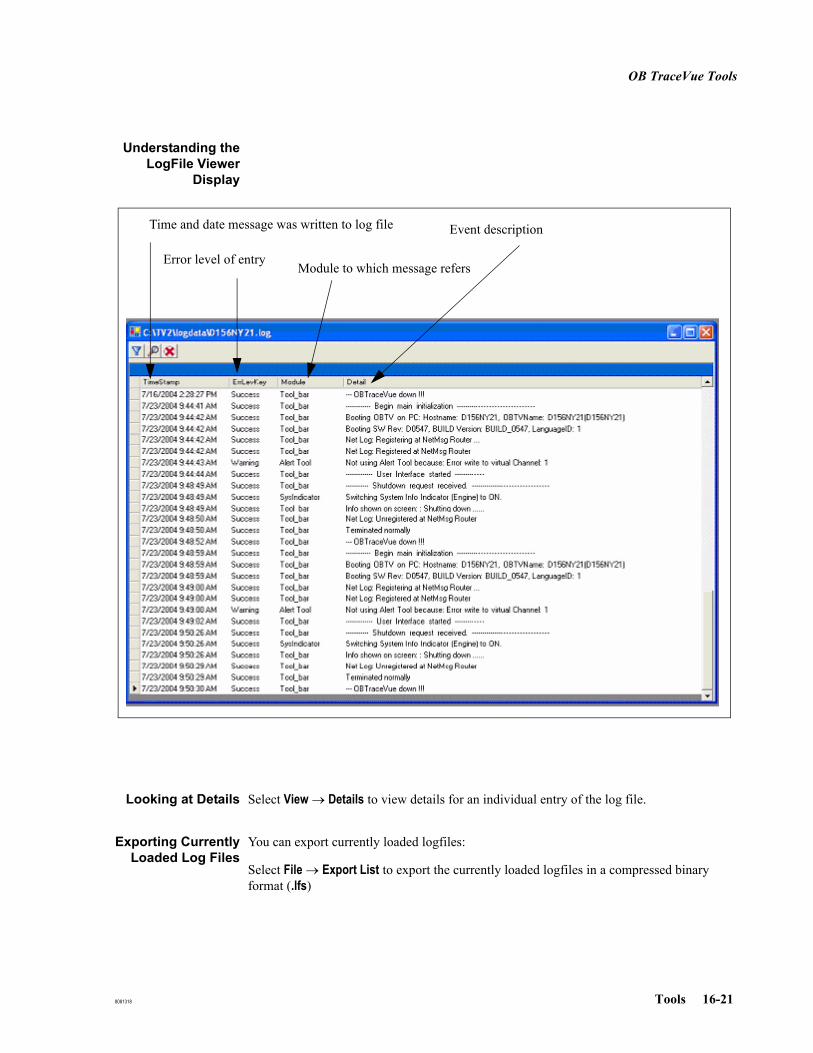
OB TraceVue Tools
8081318 Tools 16-21
Understanding theLogFile Viewer
Display
Looking at Details Select View → Details to view details for an individual entry of the log file.
Exporting CurrentlyLoaded Log Files
You can export currently loaded logfiles:
Select File → Export List to export the currently loaded logfiles in a compressed binary format (.lfs)
Time and date message was written to log file
Error level of entryModule to which message refers
Event description
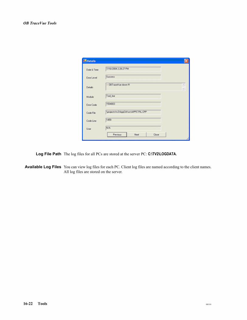
OB TraceVue Tools
16-22 Tools 8081318
Log File Path The log files for all PCs are stored at the server PC: C:\TV2\LOGDATA.
Available Log Files You can view log files for each PC. Client log files are named according to the client names. All log files are stored on the server.
OB TraceVue Tools
8081318 Tools 16-23
Installation Record
Go to OB TraceVue Support → Installation Record
The installation log file is opened in Notepad as a .TXT file.
Fetal Monitor Spy (FMSpy)
FMSpy is a software diagnostic tool for fetal monitors, connected in the “Classic” (RS232) method, that allows you to check:
The physical connection between a fetal monitor and the PC to which it is connected.
Data transfer between a fetal monitor and the PC to which it is connected.
You cannot use FMSpy to test data transfer over the OB TraceVue network.
When to Use FMSpy See Table 16-1, Standard Windows Tools, on page 16-1.
Starting FMSpy At the PC where you wish to run FMSpy:
1. Exit OB TraceVue.
If this is an OB TraceVue client, there is no need to exit OB TraceVue at the server or at any other client.
When you exit OB TraceVue at the server, all OB TraceVue clients will shut down automatically. FMSpy running at the server cannot test data transfer from a fetal monitor connected to a client.
2. Go to OB TraceVue Support → Spy
Quitting FMSpy When you have finished using FMSpy, click the END SPY button. You can also exit by pressing ALT and then E on the keyboard.
Selecting the Port Select the Port field. The system displays a list showing the available digital channels.
Select the port Digital COM 1 through Digital COM 20 directly using the Port dropdown box. If you need to select a higher COM port then type #<number>#, for example #45# for COM 45.

OB TraceVue Tools
16-24 Tools 8081318
Initializing the Port When you select a port, FMSpy initializes that port and the monitor connected to that port. If the data that FMSpy displays does not appear to be current it is probably showing old data contained in a buffer. Reselect the port.
The field next to the Port field is color coded to show you at a glance the current status of the port.
Interpreting Data FMSpy can obtain more data from a digital connection than it can from an analog connection. The following describes all the information it is possible to obtain digitally.
Monitor Info Fields After detecting a monitor, FMSpy displays information about the monitor itself in the Monitor Info fields:
Received DataFields
Heart Rate
FMSpy reports the same type of information for HR1 (heart rate1), HR2 (heart rate 2, used for twins monitoring) and MHR (maternal heart rate). This information is displayed in the Received Data section beneath the headings HR1, HR2, and MHR.
1. Number of beats per minute.
2. Signal quality. This can be:
Black Port does not physically exist. Perhaps there is no card for this port in the PC, or it has been disabled during PC setup.
Red Port is in use, but not by this FMSpy.
Yellow FMSpy is trying to detect a fetal monitor at this port.
Green FMSpy has successfully established a connection to the fetal monitor.
Field Monitor DataMonitor ID Monitor typeSerial Number Monitor's serial numberSoftware Rev Revision number of the monitor software, if available
NO_TRAN no transducer presentext external monitoringIUP internal monitoringunknown method of monitoring is unknown
Red Signal not validYellow Signal quality goodGreen Signal quality very good

OB TraceVue Tools
8081318 Tools 16-25
3. Mode. This is the mode in which the transducer is being used. The possible values are:
Toco
This indicates the way in which Toco is being monitored. The possible values for Toco are:
SpO2
The data is valid only when the monitor is equipped to measure the oxygen saturation of the blood and the check box below this field is green. A gray checkbox indicates that current data is not available (any data is from an old measurement).
Fetal Mov
If this Check Box is green, it indicates that fetal movement is detected.
Message Box FMSpy displays all the messages received from the monitor, together with the time and date so that you can verify the monitor’s operation FMSpy appends messages to a file named acqcom<comport-number>.LOG in the current directory only if the Save active button is checked.
Recorder Status Displays status information from the recorder.
AppTrace Level The AppTrace Level allows FMSpy to write messages to the acqcom<comport-number>.LOG file.
Monitor Status The status boxes display the monitor’s known condition. If the box contains a cross, the value is true. For example, if the HR 1 Twin offset box contains a cross this indicates that the Twin Offset is enabled.
NO_TRAN no transducer presentUS ultrasoundDECG direct ECGMEGC maternal ECGext MECG external maternal ECGAECG abdominal ECGUnknown transducer mode unknown
NO_TRAN no transducer presentext external monitoringIUP internal monitoringunknown method of monitoring is unknown

OB TraceVue Tools
16-26 Tools 8081318
Request and SendButtons
Some monitors can receive messages sent by FMSpy and send back answers. A request message tries to obtain a specified message from the monitor. A send message tries to send a message to the monitor. The messages received from the monitor are displayed in the Message Box.
Request Buttons Use these buttons to make the monitor display information in the Message Box. You can use this information to diagnose problems.
Test Note SendButton
Use Send Note to print a user defined test message on the monitor’s own paper.
Request Meaning
Timer Stat Not Used.
Record Stat Not Used.
Serial Stat Displays statistical data of bytes both transferred to, and received from, the monitor.
Date-Time Displays the monitor’s internal date and time.
Monitor ID Refreshes the Monitor ID field, where possible. Not all monitors can send this information to FMSpy.

OB TraceVue Tools
8081318 Tools 16-27
GetLog
GetLog compresses all available OB TraceVue log files plus some additional system information including event log data. The compressed data is stored in a single archive file. If running GetLog directly, use \tv2\prog\GetLogUI.exe. The command line version \tv2\prog\GetLogCmd.exe is used internally only.
For HA servers, run GetLog on both servers.
On active server: run GetLog using the Start menu.On standby server: run command \\<EMC Autostart Alias Name>\server\tv2\prog\GetLogUI.exe
When to useGetLog
See Table 16-3, OB TraceVue Tools, on page 16-3.
Creating andCopying an Archive
Log File
Run: OB TraceVue Support → Get Log. GetLog compresses the log files into a single archive file named c:\temp\transfer\<hostname>_log.zip.
Decompressing anArchive Log File
Any standard ZIP utility can be used to extract files from <hostname>_log.zip.
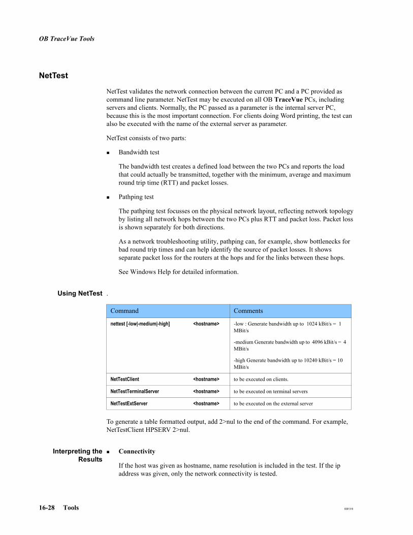
OB TraceVue Tools
16-28 Tools 8081318
NetTest
NetTest validates the network connection between the current PC and a PC provided as command line parameter. NetTest may be executed on all OB TraceVue PCs, including servers and clients. Normally, the PC passed as a parameter is the internal server PC, because this is the most important connection. For clients doing Word printing, the test can also be executed with the name of the external server as parameter.
NetTest consists of two parts:
Bandwidth test
The bandwidth test creates a defined load between the two PCs and reports the load that could actually be transmitted, together with the minimum, average and maximum round trip time (RTT) and packet losses.
Pathping test
The pathping test focusses on the physical network layout, reflecting network topology by listing all network hops between the two PCs plus RTT and packet loss. Packet loss is shown separately for both directions.
As a network troubleshooting utility, pathping can, for example, show bottlenecks for bad round trip times and can help identify the source of packet losses. It shows separate packet loss for the routers at the hops and for the links between these hops.
See Windows Help for detailed information.
Using NetTest .
To generate a table formatted output, add 2>nul to the end of the command. For example, NetTestClient HPSERV 2>nul.
Interpreting theResults
Connectivity
If the host was given as hostname, name resolution is included in the test. If the ip address was given, only the network connectivity is tested.
Command Comments
nettest [-low|-medium|-high] <hostname> -low : Generate bandwidth up to 1024 kBit/s = 1 MBit/s
-medium Generate bandwidth up to 4096 kBit/s = 4 MBit/s
-high Generate bandwidth up to 10240 kBit/s = 10 MBit/s
NetTestClient <hostname> to be executed on clients.
NetTestTerminalServer <hostname> to be executed on terminal servers
NetTestExtServer <hostname> to be executed on the external server

OB TraceVue Tools
8081318 Tools 16-29
Bandwidth Test
The first line shows the performance for less frequent and small packages. The last line shows the performance for frequent and large packages.
For bandwidth > 2048 kBit/s (2 MBit/s) the packet size has reached its maximum and instead the time between the packets is decreased. Good networks don't show a significant increase of RTT for these bandwidths. See the network specifications in the Integration Guide for an explanation of why there are no sharp limits.
The test has passed if:
measured bandwidths do not differ significantly from the requested bandwidth. (first - last line)round trip times match the specifications of the Integration Guide.
In general, good network application performance can be achieved if RTT is:
< 2 msec for small packets (first line) (1 kBit/s)~ 8 msec for packets around 32000 bytes (1 MBit/s)~ 14 msec for large packets around 65500 bytes (4 - 10 MBit/s)
and there is no packet loss for bandwidths <100 kBit/s.
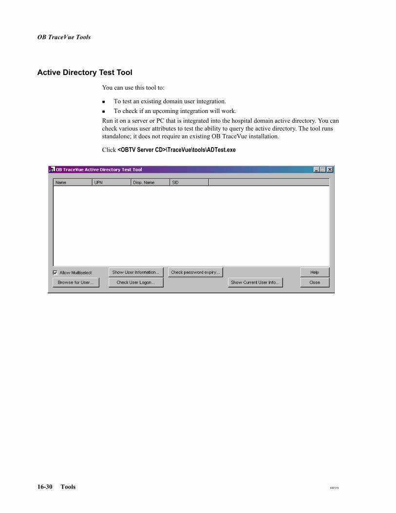
OB TraceVue Tools
16-30 Tools 8081318
Active Directory Test Tool
You can use this tool to:
To test an existing domain user integration.To check if an upcoming integration will work.
Run it on a server or PC that is integrated into the hospital domain active directory. You can check various user attributes to test the ability to query the active directory. The tool runs standalone; it does not require an existing OB TraceVue installation.
Click <OBTV Server CD>\TraceVue\tools\ADTest.exe
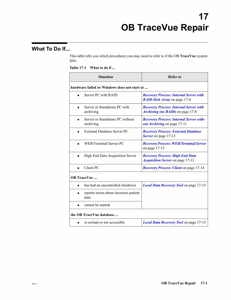
8081318 OB TraceVue Repair 17-1
17OB TraceVue Repair
What To Do If...This table tells you which procedures you may need to refer to if the OB TraceVue system fails.
Table 17-1 What to do if ...
Situation Refer to
hardware failed or Windows does not start at ...
Server PC with RAID Recovery Process: Internal Server with RAID Disk Array on page 17-4
Server or Standalone PC with archiving
Recovery Process: Internal Server with Archiving (no RAID) on page 17-8
Server or Standalone PC without archiving
Recovery Process: Internal Server with-out Archiving on page 17-11
External Database Server PC Recovery Process: External Database Server on page 17-13
WEB/Terminal Server PC Recovery Process: WEB/Terminal Server on page 17-13
High End Data Acquisition Server Recovery Process: High End Data Acquisition Server on page 17-11
Client PC Recovery Process: Client on page 17-14
OB TraceVue ...
has had an uncontrolled shutdown Local Data Recovery Tool on page 17-15
reports errors about incorrect patient data
cannot be started
the OB TraceVue database ...
is corrupt or not accessible Local Data Recovery Tool on page 17-15

What To Do If...
17-2 OB TraceVue Repair 8081318
systems with OB TraceVue Link ...
have been reinstalled from archive disks using RFA.
Link Recovery Tool on page 17-18
have been merged using the RFA merge feature
report errors when patient records are to be transferred between systems
information about archived patients is no longer available
after new system installation (no database backup available)
Retrieve from Archive (RFA Wizard) on page 17-29
after patient data was deleted using the Administration Tool
optical disks ...
are contaminated with dust Optical Disk Test Tool on page 17-23
report write errors while patient data is archived
report read errors while patient data is retrieved
the configuration of OB TraceVue ...
must be reloaded (for example, after software reinstallation with a new database)
Configuration Backup (Internal Server Only) on page 17-20
must be backed-up (for example, after changing the configuration or after new system setup, or after applying a service pack).
Table 17-1 What to do if ...
Situation Refer to
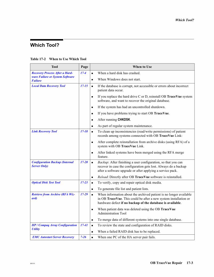
Which Tool?
8081318 OB TraceVue Repair 17-3
Which Tool?
Table 17-2 When to Use Which Tool
Tool Page When to Use
Recovery Process After a Hard-ware Failure or System Software Failure
17-4 When a hard disk has crashed.
When Windows does not start.
Local Data Recovery Tool 17-15 If the database is corrupt, not accessible or errors about incorrect patient data occur.
If you replace the hard drive C or D, reinstall OB TraceVue system software, and want to recover the original database.
If the system has had an uncontrolled shutdown.
If you have problems trying to start OB TraceVue.
After running CHKDSK.
As part of regular system maintenance.Link Recovery Tool 17-18 To clean up inconsistencies (read/write permissions) of patient
records among systems connected with OB TraceVue Link:
After complete reinstallation from archive disks (using RFA) of a system with OB TraceVue Link.
After linked systems have been merged using the RFA merge feature.
Configuration Backup (Internal Server Only)
17-20 Backup: After finishing a user configuration, so that you can recover in case the configuration gets lost. Always do a backup after a software upgrade or after applying a service pack.
Reload: Directly after OB TraceVue software is reinstalled.Optical Disk Test Tool 17-23 To verify, copy and repair optical disk media.
To generate file list and patient lists.Retrieve from Archive (RFA Wiz-ard)
17-29 When information about the archived patient is no longer available in OB TraceVue. This could be after a new system installation or hardware defect if no backup of the database is available.
When patient data was deleted using the OB TraceVue Administration Tool
To merge data of different systems into one single database.HP / Compaq Array Configuration Utility
17-41 To review the state and configuration of RAID disks.
When a failed RAID disk has to be replaced. EMC Autostart Server Recovery 7-26 When one PC of the HA server pair fails.
Recovery Process After a Hardware Failure or System Software Failure
17-4 OB TraceVue Repair 8081318
Recovery Process After a Hardware Failure or System Software FailureThis section describes the process used to recover an OB TraceVue system after a hardware failure or corruption of the Windows operating system.
Note Using the CHKDSK utility to repair files after a system server crash could result in archiving of corrupt files. Always run the Local Data Recovery Tool after running CHKDSK.
Recovery Process: Internal Server with RAID Disk Array
The OB TraceVue server with RAID disk array has three hard disks per logical drive. Every logical drive has spare disk and the array is configured to RAID level 1.
Caution: Before any operating system reinstallation is performed on an internal server with RAID, the customer must be warned that data loss will occur. A decision must be made about the most appropriate way to proceed.
If system uptime is the most important consideration, and a set of replacement RAID drives is not immediately available, accept any open episode data loss. Service personnel can then attempt reinstallation of the operating system on existing RAID drives to see if the server can be made operational.
If potential data loss from open episodes is more critical than having a running system, service personnel should remove existing RAID drives for data recovery (for example, performed by a third party company). The server is left non-operational. Replacement RAID drives should be obtained as soon as possible to get the system running again.
If a third party data recovery company is consulted by the customer, it is important that the operating system is not reinstalled and the system used again with the existing RAID drives before this can occur. This would have a significant negative impact on the chance of successfully recovering data. And, even if data could be recovered from the former RAID drives, it might not be possible to reintegrate into the system for later retrieval. Evaluation must be made on a case-by-case basis after factory analysis of recovered data. Philips cannot guarantee that lost data is recoverable. The Response Centre can consult with the factory regarding what data is most important for any data recovery attempt.

Recovery Process After a Hardware Failure or System Software Failure
8081318 OB TraceVue Repair 17-5
Single Hard DiskFailure
In case of a single hard disk failure, just replace the failed disk (indicated by a flashing red light). It is not necessary to shutdown OB TraceVue or to reboot the server PC.
Caution: Compaq ProLiant ML370 G2 / HP ProLiant ML370 G3 / HP ProLiant ML350 G4 / HP Proliant ML350 G4P:
The configuration for the replacement disk is applied automatically.
Caution: There is no default system alarm if disks fail. You need to check on a regular basis as preventive maintenance or use HP / Compaq Insight Manager for alarm distribution.
Refer to HP / Compaq Insight Management Software on page 11-9
Multiple Hard DiskFailure
In the improbable case that two or more hard disks failed at the same time and therefore the server PC does not start any more, replace the defective hardware and refer to the procedure Complete Server Reinstallation (both hard disks failed).
Other HardwareFailure (no spareserver available)
If you do not have a spare server, replace the failed components and restart the PC.
Other HardwareFailure (spare
server available)
If you have an identically configured spare server, you can use the spare hardware to restart the system within several minutes:
1. Turn off the failed server and disconnect peripheral devices (optical drives)
2. Connect the peripheral devices, network and power cables to the spare server.
3. Remove the hot swap disk drives from the failed server and install them carefully in the slots of the spare server.
Caution: Keep the drives in the same order! Do not mix the drives! Do not add any other disks.
4. Turn on the spare server and the external devices such as optical drives and UPS.
5. Run the Local Data Recovery Tool.
6. Check the system time of the PC.
7. Start OB TraceVue on the new server and on the client PCs.
8. Make sure that the revision of the PC and the RAID BIOS are up to date. Update them if necessary. For details, refer to:
BIOS Version for Compaq ProLiant ML370 G2 on page 26-3

Recovery Process After a Hardware Failure or System Software Failure
17-6 OB TraceVue Repair 8081318
BIOS Version for HP ProLiant ML370 G3 on page 27-3
BIOS Version for HP ProLiant ML350 G4 (3.0 GHz) on page 28-4
BIOS Version for HP ProLiant ML350 G4P (3.2 GHz) on page 29-3
Recovery Process After a Hardware Failure or System Software Failure
8081318 OB TraceVue Repair 17-7
Windows Does NotStart
To repair a corrupted Windows installation, try to use the "safe mode" for booting up the operating system.
Caution: In case of a corrupted Windows installation, you must NOT perform a new installation on drive C, because this will erase all your data. Servers with RAID array do not have a backup disk D!
For the repair process you need:
The Windows Server 2003 CD-ROM
To do the repair, follow these steps:
1. Press F8 while starting the PC, to enter the boot menu.
2. Select "Safe Mode with Networking" boot option.
3. Run the Backup Tool to save the existing OB TraceVue installation and data files and templates to a secure place, such as a network location.
4. Perform a new installation on the server PC, without automatic OB TraceVue installation. See OB TraceVue Installation on page 18-1.
5. Recover the templates using the Backup Tool.
6. Recover the backup using the OB TraceVue Setup.
Recovery Process After a Hardware Failure or System Software Failure
17-8 OB TraceVue Repair 8081318
Recovery Process: Internal Server with Archiving (no RAID)
The OB TraceVue Server with archiving has two hard disks:
The C: drive represents the server’s first hard disk.The D: drive represents the server’s backup hard disk.
Primary Hard DiskFailure
It is possible to recover the system from the backup disk.
1. Replace defective hardware
a. Identify the hard disks. Refer to IDE Hard Disk (Evo D530)/SATA Hard Disk (dc7100/dc7600/dc7700/rp5700) on page 13-7.
b. Install the new primary hard disk.
2. Remove the backup harddisk to prevent erasure of backup data.
It is essential to remove the D:\ drive (that is, to unplug the power and the data cable), otherwise the recovery process will not succeed.
3. Install Windows as described in Windows Server 2003 / XP Professional Installation.
a. Locate the file or printout of the installation record. This should have been saved after the initial installation of the server. See Reviewing and Printing the Configuration Record. This file specifies the PC name which is required when you reinstall the operating system.
Caution: Do not install OB TraceVue automatically in this step.
4. Re-install the backup harddisk.
Recovery Process After a Hardware Failure or System Software Failure
8081318 OB TraceVue Repair 17-9
5. Install OB TraceVue
a. Start Windows Explorer and check drive letters. See Checking and Changing Drive Letters
b. Rename the directory D:\TV2 to D:\TV2OLD. This is now your recovery source. If it is not possible to rename the directory, reboot the PC.
c. Copy D:\TV2OLD to C:\TV2OLD. This is now your backup.
d. Install OB TraceVue. Configure the system with the options and setting specified in the installation record file or printout (see Print and Back-Up Configuration Record on page 5-34.
e. Reboot the PC, but do not start OB TraceVue.
f. Stop the NetMsgService: MyComputer → Manage → Services and Applications → Services → select NetMsgService → Stop.
g. Delete the directory D:\TV2. If it is not possible to delete the directory, reboot the PC and try again.
h. Rename the directory D:\TV2OLD to D:\TV2.
i. Delete the file C:\TV2\DB\TRACEVUE.DB (This is an empty database.)
j. Start the NetMsgService: MyComputer → Manage → Services and Applications → Services → select NetMsgService → Start.
k. Run the Local Data Recovery Tool.
l. Start OB TraceVue. The systems should now be working correctly, with all data visible.
m. Delete C:\TV2OLD.
Secondary HardDisk Failure
1. Start PC in Safe Mode.
2. Verify that the page file size for drive C: is at least 80 MB.(Control Panel → System → Advanced → Performance Options).
3. Install, partition and format the new secondary hard disk as described in Secondary Hard Disk Drive (for Storage Systems) on page 13-7.
4. Verify the Virtual Memory settings. See Virtual Memory on page 19-9.
5. Run the Local Data Recovery Tool.
6. Reboot the Server PC.
Recovery Process After a Hardware Failure or System Software Failure
17-10 OB TraceVue Repair 8081318
Complete ServerReinstallation (both
hard disks failed)
In summary, to reinstall OB TraceVue for the purpose of system recovery the following tasks must be completed:
Install and format the new hard disks.Install Windows.Reinstall OB TraceVue with a new database.Reload archived data.
Caution: You must follow the steps exactly in the order they are set out in these procedures. If you fail to do so, archived data may be lost, and recovery may not be possible.
1. Locate the file or printout of the installation record, which should have been saved after the initial installation of the server (see Reviewing and Printing the Configuration Record on page 5-34). The file specifies the PC name which is needed when you reinstall the operating system.
2. Install Windows as described in Windows New Installation on page 19-5 using the PC name specified in the installation record.
3. Install OB TraceVue with a new database. Use the old installation record printout to select exactly the same configuration as before. After Setup, verify the configuration by comparing the new and the old installation record printout.
Note Make sure that the OB TraceVue Shell Autostart option is not set.
4. Reboot, but do not start OB TraceVue.
5. Run the Configuration Backup tool to reload the most recent configuration back up. See also Configuration Backup (Internal Server Only) on page 17-20.
6. The password for connecting a network based storage share is not backed up for security reasons. If such a password is required, it must be re-entered manually after configuration reload. Run setup on the archiving PC.
7. Use RFA to recover patient data from archive, going from more recent to less recent. For details on how use the RFA tool, please refer to Retrieve from Archive (RFA Wizard) on page 17-29.
8. Start OB TraceVue at the server.
9. Start OB TraceVue at each client. The client setup program runs automatically and reboots the PC when finished.
10. Use a new optical disk for archiving.
Windows does notStart
Install Windows and OB TraceVue according to the process described in Primary Hard Disk Failure on page 17-8. Start with 3. Install Windows as described in Windows Server 2003 / XP Professional Installation.
Recovery Process After a Hardware Failure or System Software Failure
8081318 OB TraceVue Repair 17-11
Recovery Process: High End Data Acquisition Server
Complete High EndData Acquisition
ServerReinstallation
1. Locate the file or printout of the installation record, which should have been saved after the initial installation of the server (see Reviewing and Printing the Configuration Record on page 5-34). The file specifies the PC name which is needed when you reinstall Windows.
2. Install Windows as described in Windows New Installation on page 19-5 using the PC name specified in the installation record.
3. If applicable, install the serial port server device driver as described in Installing and Setting up a Serial Port Server on page 6-13.
4. Install the OB TraceVue client software. Use the old installation record printout to select exactly the same configuration as before. After Setup, verify the configuration by comparing the new and the old installation record printout.
Windows does notStart
Repair of a corrupt Windows installation is not supported on the high end data acquisition server. Reinstall the server, refer to Complete High End Data Acquisition Server Reinstallation.
Recovery Process: Internal Server without Archiving
Caution: All data is erased when you use this procedure.
The server does not have a backup disk. You must, therefore, replace the hard disk, and then you must reinstall Windows and OB TraceVue.
Complete ServerReinstallation
1. Locate the file or printout of the installation record, which should have been saved after the initial installation of the server (see Reviewing and Printing the Configuration Record on page 5-34). The file specifies the PC name which is needed when you reinstall Windows.
2. Install Windows as described in Windows New Installation on page 19-5 using the PC name specified in the installation record.
3. Install OB TraceVue. Use the old installation record printout to select exactly the same configuration as before. After Setup, verify the configuration by comparing the new and the old installation record printout.
Note Make sure that the OB TraceVue Shell Autostart option is not set.
4. Reboot, but do not start OB TraceVue.
5. Run the Configuration Backup tool to reload the most recent configuration back up. See also Configuration Backup (Internal Server Only) on page 17-20.
6. The password for connecting a network based storage share is not backed up for

Recovery Process After a Hardware Failure or System Software Failure
17-12 OB TraceVue Repair 8081318
security reasons. If such a password is required, it must be re-entered manually after configuration reload. Run setup on the archiving PC.
7. Start the OB TraceVue Server.
8. Start OB TraceVue at each client. The client setup program runs automatically and reboots the PC when finished.
Windows does notStart
Repair of a corrupt Windows installation is not supported on systems without archiving. Reinstall the server, refer to Complete Server Reinstallation.
Recovery Process After a Hardware Failure or System Software Failure
8081318 OB TraceVue Repair 17-13
Recovery Process: External Database Server
Caution: All data on the external database server is erased when you use this procedure. The database can be restored from a customer’s backup.
Complete ExternalDatabase Server
Reinstallation
1. Locate the file or printout of the installation record, which should have been saved after the initial installation of the server (see Reviewing and Printing the Configuration Record on page 5-34). The file specifies the PC name which is needed when you reinstall Windows.
2. Install Windows as described in Windows New Installation on page 19-5 using the PC name specified in the installation record.
3. Install the OB TraceVue client software. Use the old installation record printout to select exactly the same configuration as before. After Setup, verify the configuration by comparing the new and the old installation record printout.
4. Restore the external database, (see the External Database Guide).
Windows does notStart
Repair of a corrupt Windows installation is not supported on the external database server. Reinstall the server, refer to Complete External Database Server Reinstallation.
Recovery Process: WEB/Terminal Server
Complete WEB/Terminal Server
Reinstallation
1. Locate the file or printout of the installation record, which should have been saved after the initial installation of the server (see Reviewing and Printing the Configuration Record on page 5-34). The file specifies the PC name which is needed when you reinstall Windows.
2. Install Windows as described in Windows New Installation on page 19-5 using the PC name specified in the installation record.
Note The OB TraceVue client software must be installed from CD using Add/Remove Programs. Do not use the Explorer to start setup.exe.
3. Install the OB TraceVue client software. Use the old installation record printout to select exactly the same configuration as before. After Setup, verify the configuration by comparing the new and the old installation record printout.
Windows does notStart
Repair of a corrupt Windows installation is not supported on the WEB/Terminal server. Reinstall the server, refer to Complete WEB/Terminal Server Reinstallation.
Recovery Process After a Hardware Failure or System Software Failure
17-14 OB TraceVue Repair 8081318
Recovery Process: Client
Complete ClientReinstallation
1. Locate the file or printout of the installation record, which should have been saved after the initial installation of the system (see Reviewing and Printing the Configuration Record on page 5-34).
2. Install Windows as described in Windows XP Professional New Installation on page 19-7. When you are prompted for the PC name, use the name given to the client during initial installation (see printout of installation record).
3. Install the OB TraceVue client software. Use the old installation record printout to select exactly the same configuration as before. After Setup, verify the configuration by comparing the new and the old installation record printout.
Windows does notStart
Repair of a corrupt Windows installation is not supported on a client PC. Reinstall the server, refer to Complete Client Reinstallation.

Local Data Recovery Tool
8081318 OB TraceVue Repair 17-15
Local Data Recovery ToolThis tool is available at the Internal Server PC. On high availability systems, this tool is also available at the external database server PC.
The Local Data Recovery tool repairs and validates as much of the OB TraceVue database as possible from uncorrupted backup database and backup patient files.
The tool is launched automatically if the most recent system shutdown was not performed correctly - for example, if the server crashed.
Note The length of time needed for data recovery depends on the size of the database and the number of open episodes. It can take from minutes to hours.
Using the Local Data Recovery Tool
Running the LocalData Recovery Tool
Do not stop this tool while it is working. Some operations may take several minutes to several hours, depending on the amount of data in the database.
1. Shutdown OB TraceVue at the server
2. Go to Start → Programs → TraceVue Support, choose Local Recovery Tool.
3. In the TraceVue Local Data Recovery Tool window choose Start.
To minimize the risks of data loss, the tool automatically performs a full database validation.
Follow the instructions on screen. You can click Show Log to see a more detailed progress status.
From Rev F.00, the tool finds the archive index without user interaction. It is no longer necessary to insert the most recent archiving disk.
Logfile The Local Data Recovery Tool creates a recovery log file (C:\TV2\logdata\RecoveryTool.log) that you can open with the OB TraceVue Log File browser.
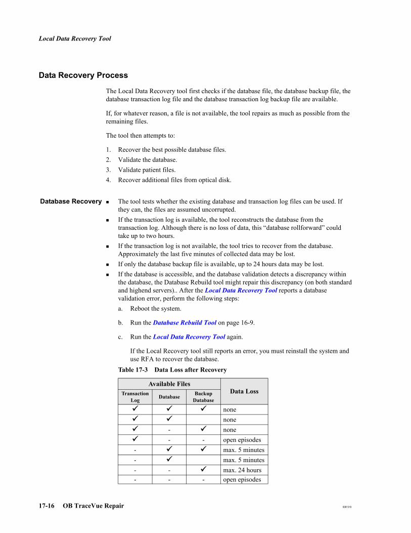
Local Data Recovery Tool
17-16 OB TraceVue Repair 8081318
Data Recovery Process
The Local Data Recovery tool first checks if the database file, the database backup file, the database transaction log file and the database transaction log backup file are available.
If, for whatever reason, a file is not available, the tool repairs as much as possible from the remaining files.
The tool then attempts to:
1. Recover the best possible database files. 2. Validate the database.3. Validate patient files.4. Recover additional files from optical disk.
Database Recovery The tool tests whether the existing database and transaction log files can be used. If they can, the files are assumed uncorrupted. If the transaction log is available, the tool reconstructs the database from the transaction log. Although there is no loss of data, this “database rollforward” could take up to two hours.If the transaction log is not available, the tool tries to recover from the database. Approximately the last five minutes of collected data may be lost.If only the database backup file is available, up to 24 hours data may be lost.If the database is accessible, and the database validation detects a discrepancy within the database, the Database Rebuild tool might repair this discrepancy (on both standard and highend servers).. After the Local Data Recovery Tool reports a database validation error, perform the following steps:a. Reboot the system.
b. Run the Database Rebuild Tool on page 16-9.
c. Run the Local Data Recovery Tool again.
If the Local Recovery tool still reports an error, you must reinstall the system and use RFA to recover the database.
Table 17-3 Data Loss after Recovery
Available FilesData Loss Transaction
Log Database Backup Database
nonenone
- none- - open episodes
- max. 5 minutes- max. 5 minutes- - max. 24 hours- - - open episodes

Local Data Recovery Tool
8081318 OB TraceVue Repair 17-17
Database Validation The validation process tests the integrity of the database. Indexes, foreign key constraints and primary keys are examined. The tool reports any errors found and is able to correct some errors automatically.
Patient FileRecovery
This validation process examines each patient trace file held on the server. Any trace file found to be corrupted is replaced by a copy of its (uncorrupted) backup.
When a trace file is replaced by its backup all associated files (for example the notes file) are also replaced.
When a patient is discharged her files are deleted from the server. The patient file validation process completes any failed patient file deletions so freeing wasted space on the hard disk(s).
Archive Recovery This process recovers data from episodes that were closed after the last database backup, but are available because they are stored in the archive.
Optical Disks
You must provide the most recent disk when running the archive recovery. This determines which episodes need to be recovered.
Caution: Ensure you provide the correct disk.
Network Based Storage
The tool finds the archive index without user interaction, and recovers the patient data automatically from the archive location.

Link Recovery Tool
17-18 OB TraceVue Repair 8081318
Link Recovery ToolThe Link Recovery Tool helps to identify and repair inconsistent patient records on linked OB TraceVue systems.
It was originally developed for use exclusively with linked systems. The “Link Recovery” tool is also used when merging systems or creating new links between systems. The purpose of the tool in this case is to generate the reports, which help to create a successful system “merge” or “link”.
It can run on any OB TraceVue PC that has a network connection to each group of linked systems to be merged. The other systems do not have to have the OBTV-link option installed. It can also run on a standalone system.
When to Use the Link Recovery Tool
Use this tool when OB TraceVue Link patient record transfer fails due to invalid or inconsistent patient record state among connected systems.
The Link Recovery Tool must be used after complete reinstallation from archive disks (using RFA) of a system that is connected to other OB TraceVue systems with OB TraceVue Link and participated in patient record transfer.
The Link Recovery Tool must be used before and after performing a merge of two systems with RFA Index Merge Tool. See also System Upgrades, Merging or Linking Systems on page 23-6.
Run this tool to identify inconsistencies of unique patient identifier usage across linked systems. These inconsistencies can prevent OB TraceVue Link from working properly. Inconsistencies with unique patient identifiers must be cleaned up manually.
Prerequisites
Before starting the Link Recovery tool, make sure that:
a network connects the internal server PCs of the involved systems.
the close process is finished for all episodes that have been transferred to other systems. Wait for 15 minutes until the data is written to the optical disk (until optical disk activity has finished) and exported to the external database.
Execute the update archive tool (see Using Update Archive Tool on page 16-8) choosing the option "no".
OB TraceVue is shut down on all PCs on which the Link engine is installed (normally the external server PCs). This prevents further OB TraceVue link transfers during the time of link status assessment and recovery. Do not restart OB TraceVue again on these PCs until the link recovery is finished.
Link Recovery Tool
8081318 OB TraceVue Repair 17-19
Using the Link Recovery Tool
Where to Run theLink Recovery Tool
Link Recovery needs to run on a PC that has a direct network connection to all internal servers of the linked systems.
Running the LinkRecovery Tool
1. Shutdown OB TraceVue at all PCs where the Link engine is installed. This is normally the external server of an OB TraceVue system.
2. Start the Link Recovery Tool.
3. Follow the instructions on screen. Configure all involved systems. You can always cancel or restart the recovery process using the Cancel or Back buttons.
4. Complete the link recovery. Follow the instructions on screen.
5. Restart OB TraceVue on all PCs where it has been previously shut down.
Caution: Ensure that all linked internal servers are configured. Failure to do so will result in incorrect patient states. Double charting could result.
Generated Reportsand Log Files
The tool generates reports during the link recovery process. The reports can be found in the directory C:\Tv2\tools\LinkRecover.
To review the reports open c:\tv2\tools\LinkRecoverReports.xls (Office 2003). The file also contains a description of the reports.
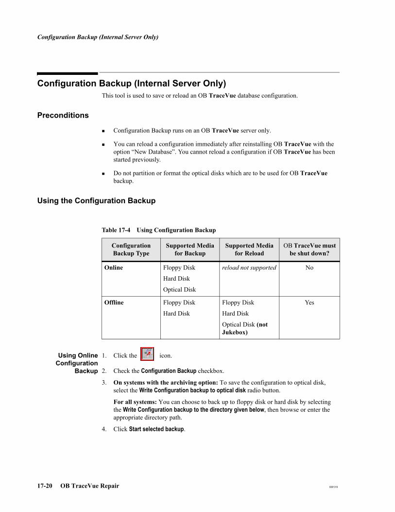
Configuration Backup (Internal Server Only)
17-20 OB TraceVue Repair 8081318
Configuration Backup (Internal Server Only)This tool is used to save or reload an OB TraceVue database configuration.
Preconditions
Configuration Backup runs on an OB TraceVue server only.
You can reload a configuration immediately after reinstalling OB TraceVue with the option “New Database”. You cannot reload a configuration if OB TraceVue has been started previously.
Do not partition or format the optical disks which are to be used for OB TraceVue backup.
Using the Configuration Backup
Using OnlineConfiguration
Backup
1. Click the icon.
2. Check the Configuration Backup checkbox.
3. On systems with the archiving option: To save the configuration to optical disk, select the Write Configuration backup to optical disk radio button.
For all systems: You can choose to back up to floppy disk or hard disk by selecting the Write Configuration backup to the directory given below, then browse or enter the appropriate directory path.
4. Click Start selected backup.
Table 17-4 Using Configuration Backup
Configuration Backup Type
Supported Media for Backup
Supported Media for Reload
OB TraceVue must be shut down?
Online Floppy Disk
Hard Disk
Optical Disk
reload not supported No
Offline Floppy Disk
Hard Disk
Floppy Disk
Hard Disk
Optical Disk (not Jukebox)
Yes
Configuration Backup (Internal Server Only)
8081318 OB TraceVue Repair 17-21
Using OfflineConfiguration
Backup
1. Start the Configuration Backup Tool.
2. Browse the appropriate directory path.
3. Click Start Backup.
Using OfflineConfiguration
Reload
Prerequisites:
You can only reload a full configuration immediately after reinstalling OB TraceVue with the option New Database. You cannot reload a full configuration if OB TraceVue has been started previously.
You must be logged in as Administrator.
The system must have been installed with exactly the same settings (version and options) and Service Packs as were previously installed. Use the printout of the configuration record (see Reviewing and Printing the Configuration Record on page 5-34) to select the same options.
To reload a configuration from floppy disk, hard disk, or optical disk:
1. Go to Start → Programs → OB TraceVue Support → Configuration Backup
2. Click Start Reload. Browse the appropriate directory path.
To reloading from optical disk select <drive_letter>:\DBBACKUP\OBTVCFG.BAK
3. Click OK
The configuration is reloaded from the file into the database.
4. Start each client. Setup will be started automatically.
The configuration reload is audited in install.txt. The entry shows the creation time, revision and OB TraceVue service pack level of the backup file.
Using OfflineConfiguration
Import
If OB TraceVue was already started after an installation with a new database, you can reload some, but not all, of the configuration data. The intended use for this feature is to copy configuration data entered into a separate system to a running system of the same revision during an upgrade.
Prerequisites:
Backup files must have been generated with the same database version.
OB TraceVue must be offline (ie, not running)

Configuration Backup (Internal Server Only)
17-22 OB TraceVue Repair 8081318
Table 17-5
Configuration EntityAdding
new entries
Update matching
entries
Delete un matching
entries
Fetal Monitor connections (serial or network)
No No No
System Configuration No No No
System Manager’s Configura-tion
Yes Yes No
Remote Fetal Monitors Yes Yes No
Users (including Active Direc-tory integration)
Yes Yes No
Overviews Yes Yes No
PC Configuration No No No
PC Defaults Sets Yes Yes No
Locations Yes Yes No
Alarm Settings/Default Sets/ NST
Yes Yes No
Charting Configuration Maps Yes Yes No
Forms Page configuration Yes Yes No
Printing Maps Yes Yes No
Value Table Data (can be done with the value table editor)
No No No
Optical Disk Test Tool
8081318 OB TraceVue Repair 17-23
Optical Disk Test ToolThe Optical Disk Test Tool should only be used by FSEs and by trained biomedical engineers at the customer site to check a customer’s OB TraceVue optical disk.
Note Severe dust contamination could cause the optical disk media to become corrupted. This could mean that some patient files can no longer be retrieved. If the disk became corrupt during archiving, then cleaning the media later on does not solve the problem.
Use the Optical Disk Test Tool to:
Low Level Check - Check each data block on the optical disk for errors.
Disk Copy - Copy a disk block by block so that it is possible to create a “refreshed” (that is, easier to read) copy of all readable blocks of a source disk.
File System Check - Starts chkdsk, which repairs the disk file system.
File Check - Check each archive file on the optical disk after the file system has been repaired. The file check creates two list files containing the names of the files with errors and the names of the files without errors.
Create Patient List - Creates two lists of patient names containing the names patient records with errors and the names of the patient records without errors.
Requirements
SCSI interface with at least two optical disk drives connected for disk copy, or one optical disk drive for the other functions.
OB TraceVue must not be running.
No application which accesses the optical disk must be running.
To create patient lists:
The database file that corresponds to the optical disk.
OB TraceVue server or standalone PC with archiving.

Optical Disk Test Tool
17-24 OB TraceVue Repair 8081318
Using the Disk Test Tool
Using with OpticalDrives
Select an optical drive in the combobox.If you want to change disks, use the Eject button.
Using with MediumChanger (Jukebox)
Click the Select disk… button,In the dialog, select an optical disk.
Optical DiskRecovery Process
1. Run a Low Level Check. If the test tool reports errors, continue with step 2.
2. Copy the optical disk using Disk Copy. Perform the following steps on the copied disk.
3. Repair the file system of the disk by running File System Check.
4. Generate a list of defect files using File Check.
5. At the server or standalone generate lists of patients using Create Patient List.
To run the Disk TestTool
1. Shut down OB TraceVue.
2. Standalone drives: write-protect the optical disk media! If the disk is not write-protected, the disk tool reports an error, and the optical disk is ejected.Medium changers: the optical disks must not be write-protected.
3. Inspect / clean the optical disk media as necessary. Instruct the customer on how to clean the media.
4. Run: C:\TV2\PROG\DISKTOOL.EXE
5. Enter password. Two passwords are accepted by the tool:
6. Select the optical drive:If running on medium changer select the disk you want to check.
Viewing ErrorStates
The Traffic Light in the main window shows the current error state. The states are:
Password Type Functionality Enabled
Biomed password Low Level CheckCreate Patient Lists
FSE/Response Center password All functionality
Traffic Light Color Meaning
Green No errorsYellow One or more error(s) occurred, but these errors could be
recovered using one or more retriesRed One or more unrecoverable error(s) occurred.
Traffic Light not visible Disk Test Tool is idle.

Optical Disk Test Tool
8081318 OB TraceVue Repair 17-25
Error Log Window You can also view errors in the error log window. Double click a message to get a more detailed description of a particular message.Click <<Hide Log if you do not wish to display the error log window.Click Show Log>> to display the error log window.
Disk Test ToolProgress and
Status
The disk icon in the main window rotates when a Disk Test Tool function is running.
The progress bar in the main window displays the percentage complete of a Disk Test Tool function.
Log File The Disk Test Tool writes a general event log file C:\DISKTOOL.LOG. This file contains the following information from the error log window:
Which action started.Action result.User interrupts.Chkdsk output.
Low Level Check
1. Start the Disk Test Tool, click Start Disk Check.
The verification process starts; this can take up to one hour. Errors are displayed in the error window.
2. Click Eject Disk to remove the optical disk from the drive.
Disk Copy
Use Disk Copy to create a working copy of an archive disk when the Low Level Check reports errors. Later recovery steps may change the data on the archive disk. Do not use Disk Copy as a backup mechanism.
This function is available only when you enter the FSE/Response Center password.
Requirements At least two optical disk drives must be connected.
The source disk must be write protected.
The destination disk must be the same type and format as the source disk.
Note Disk copy can take hours depending on the number of retries. For example, a customer disk with 600 bad blocks, of which 300 are not readable, copied with 15 external retries, takes about 14 hours.
1. Label the destination disk, for example, Copy of HP SERV, <date/time>.

Optical Disk Test Tool
17-26 OB TraceVue Repair 8081318
2. Make sure that disks are inserted in the source and destination drives.
3. Start the Disk Test Tool, click the Disk Copy tab.
4. Select the destination disk drive in the Select Destination Disk Drive field.The source disk drive is already selected in the Select Disk Drive field in the Optical Disk Test Tool main window.
5. Specify the number of external retries the tool should make if it cannot read a block on the source disk. To do this enter a value in the Read Retries field. The minimum number of retries is one, the maximum number is 30.
6. Click Start Disk Copy to start the low level disk copy.
7. When the disk copy function has successfully been completed, the label file of the copy is modified. The section [DISKTOOL] with the value COPY=TRUE is added. From this you are able to identify a disk copy.
File System Check
This function is only available when you enter the FSE/Response Center password.
Caution: Avoid using this tool with the original customer disk! This is because chkdsk may exclude blocks from the file system by marking them as bad. This can result in patient data loss!
Use the working copy you created using Disk Copy in the previous steps
1. Start the Disk Test Tool, click the File System Check tab.
2. Click Start Disk Check.
The chkdsk program starts.
Errors are displayed in the error log window. The Disk Test Tool itself is unable to detect whether chkdsk found any errors on the disk, therefore you must check the error log window to see if errors were detected.
Sometimes chkdsk does not fix the errors in one run. In this case run chkdsk until it does not show any error or any message about a repair action it performed. Each run of chkdsk usually takes less than one minute.

Optical Disk Test Tool
8081318 OB TraceVue Repair 17-27
Archive File Check
This function is available only when you enter the FSE/Response Center password.
1. Start the Disk Test Tool, click the Archive File Check tab.
2. Click Start File Check.
3. The Archive File Check function decompresses and checks the following files:
A message is displayed if an error occurs during decompression.
The file check creates the hidden directory \FILELIST on the optical disk. It writes to the following hidden files in the directory:
Do not manipulate these files manually. These files contain the source data out of which the patients lists are created (see Checking Patient Data on page 17-28).
4. Click the Show the file lists button to display the result lists of the file check. If no files were found an error message is displayed.
OB TraceVue Version Files Checked Files NOT Checked
A.01.xx disks Archive files:Trace Datathe NotesAudit TrailNST Report
Patient database files in the directory:\TRACEVUE\DBBACKUP
A.02.xx (or higher) disks
Archive files:Trace Datathe NotesAudit TrailNST ReportPatient database dataArchive index is checked using CRC.
BADFILE.TXT List of files where an error occurred during decompression
GOODFILE.TXT List of files successfully decompressed.
MISSING.TXT List of missing files.
UNREFERENCED.TXT List of files not referenced in the database.

Optical Disk Test Tool
17-28 OB TraceVue Repair 8081318
Checking Patient Data
After the data recovery process has been performed, you can create two lists of patient names:
A list of patient names with errors.
A list of patient names without errors.
Creating PatientLists
1. Start the Disk Test Tool on the internal server PC.
2. Click the Create Patient Lists tab.
3. Select which type of list you wish to create (bad files or good files).
4. Select Create Patient Information to generate the following files in the optical disk \FILELIST directory (both files are read only and hidden):
5. Select Show Patient Information to start a Notepad which displays the patient list files. Use Notepad to save or print the data as required.
BADPAT.TXT List of patients with errors in the archive files.
GOODPAT.TXT List of patients without errors in the archive files.
MISSINGPAT.TXT List of patients with missing archive files.
Retrieve from Archive (RFA Wizard)
8081318 OB TraceVue Repair 17-29
Retrieve from Archive (RFA Wizard)The RFA tool is able to restore patient data, stored on an optical disk, to the OB TraceVue internal and external database. This means that you are able to retrieve the archived patient episodes when you run OB TraceVue or run statistics using the external database.
You can retrieve single or multiple patients from the optical disk or a whole set of available archived patients.
It is also possible to merge archived data from different OB TraceVue systems into a single database. This can be necessary when multiple OB TraceVue systems should be merged to one system with more client PCs.
It can restore transfer information from linked systems after recovery.
The medical record number, social security number and patient identification must be unique. If imported patients have the same patient identification on another system, the older patient record is marked with a red cross in the Identify/Search Patient (Rolodex) screen and new episodes cannot be added for this patient record. Merging optical disks from different systems may result in “disabled patient-records” if there are patient records with conflicting identifiers.
The external database does not require unique patient identifiers. Therefore, patient records which have duplicate identifiers are not marked as a disabled record (with a red cross). In reports and statistics, these count as separate patients.
Caution: In case of hardware failures or system corruptions check Recovery Process After a Hardware Failure or System Software Failure on page 17-4 before reinstalling OB TraceVue.
RFA should only be used as the last resort if recovery of the OB TraceVue database is not possible from a backup database.
Requirements Optical disk drive (to read data from optical disk).
Storage enabled in OB TraceVue software.
OB TraceVue database engine is running.

Retrieve from Archive (RFA Wizard)
17-30 OB TraceVue Repair 8081318
Limitations The RFA tool can only be used with the current release of OB TraceVue. However, the tool can be used with media written by previous OB TraceVue versions.
The RFA tool does not run if OB TraceVue or other support tools are running.
OB TraceVue does not run if the RFA tool is running.
Caution: On a system without Newborn option, you must not use Retrieve from Archive (RFA Wizard) to retrieve data from optical disks archived on a system installed with Newborn option. Retrieving newborn episodes in a system without Newborn option may lead to unpredictable results.

Retrieve from Archive (RFA Wizard)
8081318 OB TraceVue Repair 17-31
Checks Before Running the RFA Tool
The RFA tool reads all patient data directly from the network storage location. Therefore it is necessary that all optical disks are migrated to the network storage location before running patient data import from this location.
Before you run the RFA tool you must do the following at the OB TraceVue server:
1. Not required for new installations. For linked systems only: Run the Link Recovery Tool to check the uniqueness of patient identification fields among the linked systems before carrying out the RFA merge.
2. Not required for new installations: Run the Local Data Recovery Tool to verify that the current database has no errors (see page 17-15).
3. Not required for new installations: Backup the OB TraceVue database and save the backup file to a secure location:
a. Run OB TraceVue.
b. In the Configuration Toolbar click the Backup icon.
c. Select Backup of Main Database and press Start selected backup.
d. Shut down OB TraceVue.
e. Copy the database backup file to a safe location:
i. Create <drive>1:\SAVEDB\
ii. Copy <drive>:\TV2\DBBACKUP\TRACEVUE.DB and TRACEVUE.LOG to <drive>:\SAVEDB
For more information refer to the System Administration and Configuration Guide.
4. Make a backup of the external database (see the External Database Guide).
5. Shut down OB TraceVue on the internal server.
6. Close all applications that may access the optical disks, such as Windows Explorer.
7. Verify the customer’s optical disks. To do this run the Optical Disk Test Tool: Insert the OB TraceVue CD-ROM and run C:\TV2\PROG\DISKTOOL.EXE
For more information refer to: Optical Disk Test Tool on page 17-23.
1. D on systems with 2 hard disks, C on systems with RAID

Retrieve from Archive (RFA Wizard)
17-32 OB TraceVue Repair 8081318
Special Considerations When Using RFA on Linked Systems
If you use RFA to restore an internal database of a system that is part of a group of linked systems, the tokens belonging to patient records received from other systems may get lost.
If this occurs, it means that no system has the patient record token, and therefore it is not possible to create new episodes for the patient. The patient documentation cannot be continued until the token is repaired.
The following methods are available to repair the token:
1. Full Token Repair
This repairs the tokens of all affected patient records. The tokens are restored to the system where they resided before the RFA database restore was carried out.
a. Run RFA Recovering Lost Transfer States (Recovering Lost Transfer States on page 17-36) on the restored system. You need optical disks of ALL linked systems.
b. Run the Link Recovery Tool.
2. Quick Token Repair
This repairs the tokens of all affected patient records. Usually, the tokens are restored to the system where the last episode of the affected records was closed. You may need to transfer patient records to the repaired system using "Pull from Link" at the Identify/Search Patient screen (Rolodex).
Use the Link Recovery Tool.
3. Individual Token Repair
This repairs the tokens of selected patient records. You may need to transfer the patient records to the repaired system using the Pull from Link feature.
Use the Token Overview and Repair dialog in the Identify/Search Patient screen (Rolodex).

Retrieve from Archive (RFA Wizard)
8081318 OB TraceVue Repair 17-33
Using the RFA Tool
The tool is password-protected. Only OB TraceVue users with System Manager permission and the permission to change patient data can login.
At the OB TraceVue server:
1. Start the RFA tool. (Go to OB TraceVue Support → Retrieve from Archive).
On a high availability server pair, you must bring the "tools" resources group online before starting the tool at the external server.
2. Click Next > to step through the wizard. Follow the on-screen instructions.
3. Only if the database is empty, you will be prompted to insert the most recent optical disk to restore the archive index. This is independent from further actions.

Retrieve from Archive (RFA Wizard)
17-34 OB TraceVue Repair 8081318
Importing Patient Data Created by OB TraceVue A.02.00 or Higher
Select the corresponding option in the Wizard to be able to import patient data created by OB TraceVue A.02.00 or higher. The patient selection dialog will appear showing all known patients (OB TraceVue A.01.x patients are not included).
Enter any required data to identify a single or several patients. It is possible to enter a time range in which the last episode of a patient was closed.
Select the patients you want to make retrievable with OB TraceVue by clicking on them, or use the buttons on the right to select and deselect them.
Pressing Start Import Data will prompt the user to insert the disk, which contains the selected data.

Retrieve from Archive (RFA Wizard)
8081318 OB TraceVue Repair 17-35
Note Be sure to have all optical disks available, because the selected data might be spread over several disks. Double click on a patient to see the name of the optical disk(s) on which the patient’s data is stored.
The data is read from the optical disk and imported into the OB TraceVue database using the OB TraceVue-Link mechanism.
If the selected data is spread over several disks, the tool will prompt the user to insert the required disk. The tool optimizes disk changes.
Importing Patient Data Created by OB TraceVue A.01.64
Importing into aSystem UsingOptical Disks
Select the corresponding option in the Wizard to be able to import patient data created by OB TraceVue A.01.64. The tool will request the disk with the required data, the patient selection dialog will appear showing all patients of the inserted disk.
Select the patients you want to make retrievable with OB TraceVue by clicking on them, or use the buttons on the right to select and deselect them.
Pressing Start Import Data will import the selected patient data into the OB TraceVue database.
Importing into aSystem Using
Network BasedStorage
When retrieving data from A.01.xx media into OB TraceVue, you must:
1. Copy the content of the optical disk to the network storage location using the optical disk migration tool, as detailed above.
2. Run Retrieve from Archive (RFA Wizard).
a. Select retrieve from A.01.xx disks.
b. Select the optical disk.
c. restore the data.
Finalizing Imported Patient Data
After importing data to the internal database on linked systems, an additional step is required to restore the patient state across linked systems. See Recovering Lost Transfer States.
Merging Patient Data
When merging two systems, there are different processes when merging from optical disks into network storage, or when merging from network storage to network storage.
If you have a whole set of “foreign” disks (e.g. because you want to merge two independent systems to one server) it is again very important to use the most recently used disk with the Merge feature.

Retrieve from Archive (RFA Wizard)
17-36 OB TraceVue Repair 8081318
Merging OpticalDisks into Network
Storage Location
Use the Optical Disk Migration Tool to copy all needed optical disks to the destination network location.
Use the RFA tool to read the archive index from the last optical disk (select optical disks) of the system to merge.
1. Use the Optical Disk Migration Tool to copy the data on the optical disks to your network based storage destination location.
2. Use the RFA tool to import the patient data:
a. Select Merge.
b. Select Optical Disk as your archive loaction (Choose this, even though you just migrated (copied) the optical disks to the network based storage location.)
c. Insert the most recent optical disk of the set to be merged. Only a small amount of data (the archive index) is read from the optical disk.
d. Select the patients to import, and start the import process.Data is read from the network based storage location because the migration tool did the copy work from the optical disks.
Merging NetworkStorage to Network
Storage
Manually copy all disk directories (that is, all directories in the storage location except the index) from the source network location to the destination network location.
Use the RFA tool to read the archive index from the source network storage location (select network path).
Recovering Lost Transfer States
When a patient is transferred between systems, the sending system transfers the patient record, together with the token to the receiving system. The token indicates on which system the responsibility for the patient record lies. If, for example, the receiving system’s database is restored before a new episode is created for that patient, the token is lost.
Recovery in OpticalDisk Based Storage
System
To repair tokens in such a case, the RFA "Recover Lost Transfer States" uses the archive disks of the linked system(s) to identify patient records where the last action was a transfer to the local system.
To recover lost transfer states:
1. Select Recover lost transfer states after RFA.
2. Click Next and follow the on-screen instructions.
3. Insert the latest archive disk of a linked system and import transfer data.
Only patient records transferred to the location displayed in the edit box are imported. The edit field should be altered only if the system name was changed and older records referring to the old system name have to be imported.
4. Click I want to import more data to import transfer data from another, linked, system. When all linked systems have been processed, exit the wizard.
Retrieve from Archive (RFA Wizard)
8081318 OB TraceVue Repair 17-37
5. Run the Link Recovery Tool to finish the token repair.
Recovery inNetwork Based
Storage System
To recover lost transfers:
1. Import data from the optical disks:
a. Insert the most recent disk of the other system
b. Insert disks as requested.
2. Import data from other network storage location, specify the path to the network storage location of the other system. The RFA tool can read all necessary data from this location.
Restoring the External Database
This feature allows the user to complete the contents of the external database by importing archived episodes (created with OB TraceVue Rev. A.02.00 or higher) from the optical disk. The intended use is to restore single or multiple patients that are missing on the external database, for example, in case of a temporary downtime of the external database server or if systems were merged.
Due to the complex process of restoring the data, it may take several hours to restore the complete data of one optical disk. The dialog shows a rough time estimation based on the data already processed.
If a customer does not need statistical reports from notes data, it is possible to exclude notes data from the restore process. This will reduce the required time for operation considerably.
It is recommended to specify a time range using Search for patients with last episode closed.... The time range should not start earlier as displayed in RFA. Episodes that were closed earlier are purged automatically.
After Running the RFA Tool
In linked systems, after restoring the database on an internal server, you must run the Link Recovery tool to set the correct patient states.Check the log file and the report files for errors.After merging disks OB TraceVue requests a new archiving disk.You may need to initiate a media change to eject the disk from the hardware.

Retrieve from Archive (RFA Wizard)
17-38 OB TraceVue Repair 8081318
Log File
The RFA tool automatically generates a log file: C:\TV2\LOGDATA\RFAWiz.txt. This file records information about:
Each action performed by the user.Each action performed by the RFA tool.Errors during operation.
Report Files
The RFA tool automatically generates the following report files:
C:\TV2\LOGDATA\RFAIntDBReport.txtC:\TV2\LOGDATA\RFAExtDBReport.txt
The report files contain records about:
Successfully imported patient recordsPatient records which could not be importedPatient records which were disabled because of patient identifiers not being unique (MRN, SSN, ID).
Full Reinstallation with New Database
When a system is fully reinstalled using a new database, the RFA tool is used to restore patient data from archive.
The internal ID of the system changes after new installation. Consequently, the new system will not accept the network storage location of the previous system for archiving. The file ID.XML in the network storage location identifies the system that is allowed to write archive data to this storage location.
After creating a new database:
1. Ensure that the current archive index from the network storage location was imported into the database using the RFA tool, as described in Importing Patient Data Created by OB TraceVue A.02.00 or Higher.
2. Delete file ID.XML in the network storage location using Windows Explorer.
Caution: If the archive index was not imported into the database, all data are lost after deleting the ID.XML file.
When OB TraceVue receives a request to archive data, the archive module writes a new archive index and a new ID.XML file marking the storage location for usage by the new system.

Retrieve from Archive (RFA Wizard)
8081318 OB TraceVue Repair 17-39
Error Messages
At Start-up
In the Main Window
Error Message Reason/Solution
The executable file is not valid. Please install correct version.
The executable file was modified after compila-tion. A possible reason is error during a copy
Invalid password Re-enter using correct password.
Another part of OB TraceVue is already running. Press OK to exit
Only one support tool or OB TraceVue can be running at any one time.
Unable to connect to TraceVue data-base
OB TraceVue database is not running. Reboot server PC and try again. Verify whether the OB TraceVue software was installed correctly if the problem persists.
Error Message Reason/Solution
Errors occurred during operation! See logfile C:\TV2\LOGDATA\RFAWiz.txt for details
An error occurred when the patient data was being imported into the OB TraceVue data-base. Affected patients are listed in the log file.
Wrong Disk! Insert Disk created with OB TraceVue Rev. A.0x.xx
The inserted disk has the wrong format. Insert correct disk.

Retrieve from Archive (RFA Wizard)
17-40 OB TraceVue Repair 8081318
In the Log File
Error Message Reason/Solution
ERROR: Importing Patient <patient_name> into TraceVue database failed
The selected patient data could not be imported into the TraceVue database. Possible reasons:
The patient is already in the database. Data import is not necessary.
Solution: Check if the patient is already in the database. Exit the RFA tool, restart OB TraceVue, and search for the patient via the patient identification screen.
You are using an incomplete backup disk.
Solution: Restart RFA and insert the original archive disk when requested.
There is already another patient in the database who has identical values entered either in the Patient ID, Medical Record Number, or Social Security Number fields.
Solution:
1. Have a look at these fields in the RFA tool main window.
2. Exit the RFA tool, start OB TraceVue.
3. Search for the patient in the patient identification page.
4. Change the conflicting items to another value or delete them.
5. Exit OB TraceVue, then restart the RFA tool and try to reimport the patient data.
INFO: Inserting Archive Loca-tion into DB failed (disk already known)orArchive Location <name of disk> could not be migrated!
The current disk is probably already known in the database.
No action is required. Ignore the message
WARNING: Duplicate records were detected in datafiles! Some patient demographics may be lost!
Patient demographics are lost because of corrupted data records. The patient records affected are marked with XXX
HP / Compaq Array Configuration Utility
8081318 OB TraceVue Repair 17-41
HP / Compaq Array Configuration UtilityFrom the internal server or a remote PC, this utility let you review and change settings for the disk array.
Locating the ArrayConfiguration Tool
1. Start Programs → HP / Compaq System Tools
2. Choose HP / Compaq Array Configuration Utility
For further information, see the HP Array Configuration Utility User Guide.
Configuring aReplacement Disk
No manual configuration is necessary:
If a disk in the array fails, the dedicated spare disk is included into the active array automatically.
If installing a replacement disk, the disk is included into the active array automatically. The former spare disk is excluded and its status is re-set to spare.

HP / Compaq Array Configuration Utility
17-42 OB TraceVue Repair 8081318

8081318 OB TraceVue Installation 18-1
18OB TraceVue Installation
IntroductionThis chapter tells you how to completely install the OB TraceVue software. This is different from the setup you perform on a new system that has come straight from the factory. A new system from the factory already has OB TraceVue pre-installed (except on the HA pair) and you can change factory defaults.
OB TraceVue setup guides you through the Setup process. Instructions at each screen tell you exactly what you need to do at that point. This chapter gives a brief outline of all possible Setup screens. The configuration you choose, however, determines exactly which screens you see.
When to Reinstall OB TraceVue You will need to reinstall OB TraceVue under the circumstances described in:
Chapter 9, Troubleshooting
Chapter 12, Repairing/Replacing Hardware and MediaIf you have installed the Windows operating system after installing a new hard disk, or because the operating system was corrupt.
Chapter 17, OB TraceVue Repair
Chapter 21, Software Only UpgradesChapter 22, Hardware and Software UpgradesChapter 23, System UpgradesAfter an upgrade that involves installing or reinstalling the operating system.
Restoring the OB TraceVue Philips Password on page 18-10If the password of the Philips user must be reset to its defaults value.
Note When you reinstall OB TraceVue and the previously installed system was enabled for Newborn, it is not possible to unselect Newborn and Forms based patient record. To remove the Newborn system setting you must completely uninstall and then reinstall OB TraceVue.

OB TraceVue Setup
18-2 OB TraceVue Installation 8081318
OB TraceVue SetupOB TraceVue setup allows you to install the software and to change system options.
Installing OB TraceVue
Prerequisites Before you can install OB TraceVue, the Windows operating system must be correctly installed.
Starting Setup You must run Setup on the internal server PC before you setup any clients.
Note On the internal server PC you must run Setup from the Installation CD. On all other PCs you can run Setup from the internal server share or from the Installation CD.
1. Logon to Windows as Windows administrator.
2. Run OB TraceVue Setup
a. Internal Server PCRun \TRACEVUE\SETUP.EXE from the Server Installation CD.
b. Client / External Server PCRun \\<server name>\server\tv2\setup\setup.exe.
c. WEB/Terminal Server PCi. In the Control Panel, start Add/Remove Programs.ii. Select Add New Programs, click the button labeled CD or Floppy.iii. Open \\<server name>\server\tv2\setup\setup.exe.
d. High Availability Server
i. Check Install internal server high availability solution if the high availability software is installed on the internal pair.
The system displays the OBTV_HOSTNAME in the dialog. The high availability server must be checked during setup on both servers in the pair.

Running Setup
8081318 OB TraceVue Installation 18-3
Changing OB TraceVue System Options
Prerequisites OB TraceVue must be correctly installed.
Starting Setup You can start the OB TraceVue Setup at any PC.
Go to Start → Programs → OB TraceVue Support → OB TraceVue Setup
It is possible to change System Settings only during a server or a standalone setup because these settings can be changed/defined only at a server.
Local settings such as Ports, Server Drives, External Interface settings, Auto Login, and Shell settings must be changed at each PC individually.
Running Setup
The following describes all the screens you may see during setup.
1. In the first screen, enter the setup password. Click Next.
2. The second setup screen is the Welcome screen. It shows the copyright notice. You do not need to make any input at this screen. Click Next to confirm that you want to continue with the setup.
3. Screen 3 is displayed. This box shows which version of OB TraceVue you are about to install. Click Next to confirm that you want to continue with the setup.
4. If Setup finds that you are trying to install the version number of OB TraceVue that is already installed on the system, it displays the Found System Screen. You must decide:
Select the option and click Next to continue.
Install the OB TraceVue software
The new system software is installed. (Refer to the section Install the OB TraceVue Software on page 18-4).
Only change database settings or system settings.
Change only port settings and/or system options, no files are overwritten. (Refer to the section System Settings on page 18-5).
Note: If you select this option, the correct port settings must be selected. If not, the port settings will reset to the default settings (that is disabled).
Uninstall OB TraceVue
Deletes existing software from PC. Use this only if you are removing OB TraceVue from the PC, but not wanting to reinstall it on this PC. (Refer to the section Uninstalling OB TraceVue on page 18-12).

Running Setup
18-4 OB TraceVue Installation 8081318
Install the OB TraceVue Software
If you select to install the OB TraceVue software you must do the following:
1. Specify whether the system you are installing is:
Network Server.Standalone.Network Client (includes external server and WEB/Terminal server).
2. Click Next to continue.
If you select a type that is different to the currently installed system type, you must confirm the change. If you install a server or standalone version where there was previously a client, you will not be able to use this PC to access the data that was previously on this PC.
Caution: If you install a client where there was previously a standalone or server, all patient data from the old server/standalone will be lost.
Click Next to confirm a change and continue.
3. Server/Standalone only
If you have told setup to install OB TraceVue over an existing version of itself you have to decide whether to keep the existing database and data files and reuse them.
Normally you select Keep existing database and data files if you decide to upgrade an existing installation. Delete an existing database only if you want to reinstall OB TraceVue with completely new settings and patient data.
Caution: If you select Delete existing database and data files all patient data will be lost.
Click Next to continue.
Option Patient Data Optical Disk Client PCs
Keep existing database and data files
Patient and configu-ration data remain.
Use current disk (current side)
No client setup required.
Delete existing data-base and data files
Patient data, and configuration data, are DELETED!
Change Optical Disk - use new disk (or second side of current disk if not yet used)
Run setup on all clients.
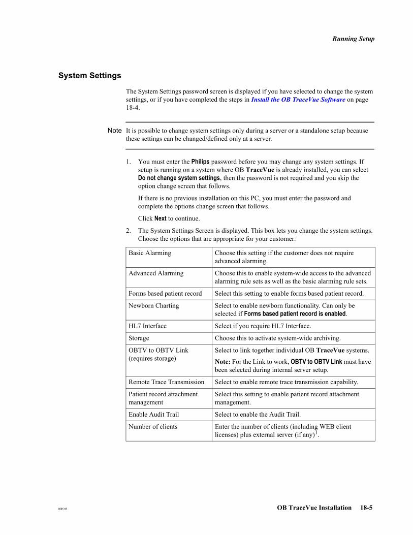
Running Setup
8081318 OB TraceVue Installation 18-5
System Settings
The System Settings password screen is displayed if you have selected to change the system settings, or if you have completed the steps in Install the OB TraceVue Software on page 18-4.
Note It is possible to change system settings only during a server or a standalone setup because these settings can be changed/defined only at a server.
1. You must enter the Philips password before you may change any system settings. If setup is running on a system where OB TraceVue is already installed, you can select Do not change system settings, then the password is not required and you skip the option change screen that follows.
If there is no previous installation on this PC, you must enter the password and complete the options change screen that follows.
Click Next to continue.
2. The System Settings Screen is displayed. This box lets you change the system settings. Choose the options that are appropriate for your customer.
Basic Alarming Choose this setting if the customer does not require advanced alarming.
Advanced Alarming Choose this to enable system-wide access to the advanced alarming rule sets as well as the basic alarming rule sets.
Forms based patient record Select this setting to enable forms based patient record.
Newborn Charting Select to enable newborn functionality. Can only be selected if Forms based patient record is enabled.
HL7 Interface Select if you require HL7 Interface.
Storage Choose this to activate system-wide archiving.
OBTV to OBTV Link (requires storage)
Select to link together individual OB TraceVue systems.
Note: For the Link to work, OBTV to OBTV Link must have been selected during internal server setup.
Remote Trace Transmission Select to enable remote trace transmission capability.
Patient record attachment management
Select this setting to enable patient record attachment management.
Enable Audit Trail Select to enable the Audit Trail.
Number of clients Enter the number of clients (including WEB client licenses) plus external server (if any)1.
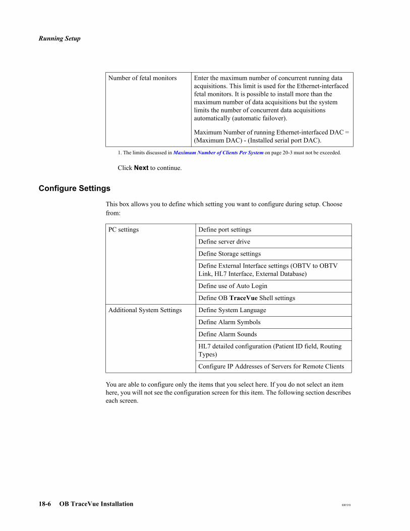
Running Setup
18-6 OB TraceVue Installation 8081318
Click Next to continue.
Configure Settings
This box allows you to define which setting you want to configure during setup. Choose from:
You are able to configure only the items that you select here. If you do not select an item here, you will not see the configuration screen for this item. The following section describes each screen.
Number of fetal monitors Enter the maximum number of concurrent running data acquisitions. This limit is used for the Ethernet-interfaced fetal monitors. It is possible to install more than the maximum number of data acquisitions but the system limits the number of concurrent data acquisitions automatically (automatic failover).
Maximum Number of running Ethernet-interfaced DAC = (Maximum DAC) - (Installed serial port DAC).
1. The limits discussed in Maximum Number of Clients Per System on page 20-3 must not be exceeded.
PC settings Define port settings
Define server drive
Define Storage settings
Define External Interface settings (OBTV to OBTV Link, HL7 Interface, External Database)
Define use of Auto Login
Define OB TraceVue Shell settings
Additional System Settings Define System Language
Define Alarm Symbols
Define Alarm Sounds
HL7 detailed configuration (Patient ID field, Routing Types)
Configure IP Addresses of Servers for Remote Clients

Running Setup
8081318 OB TraceVue Installation 18-7
Fetal MonitorConnections
(Ports)
This screen lets you define for which type of data acquisition the existing ports will be used. It is available on network clients, standalone PCs and internal server PCs (up to 20 clients).
Local: Fetal Monitor connected directly to the PC (RS-232) or via serial port server.Remote: Remote trace transmission via modem. The modem must be connected
directly to the PC (RS-232).
Ethernet: Fetal Monitors connected directly via Ethernet.
Note If serial ports are used for other purposes (e.g. UPS or modems), then the ports do not appear in the list. The maximum number of Fetal Monitor connections may be decreased.
Table 18-1 Number of Fetal Monitor Connections
Port Connection TypeNumber of FM Connection at
PCs
Localdirect RS-232 4
serial port server 16
Remote modem direct RS-232 4
Ethernet directly connected to the Ethernet 16
Maximum per PC 16

Running Setup
18-8 OB TraceVue Installation 8081318
Server Disk Drive(Backup Drive)
Specify the backup drive for the server PC. You can specify local drives only.
Archive DriveSettings
To configure Archiving on the local PC (internal server or external server), please check the box Configure Archiving and Retrieve running on this PC.
Then configure the optical disk drive(s) or the Optical Medium Changer. To use a connected medium changer (jukebox) for archiving, check Use the installed Autochanger.
Note It is not possible to assign the internal disk drives of the optical medium changer.
HL7 DetailedConfiguration
Select a Patient Identification field from the list and configure routing types. Each routing type requires an appropriate HL7 license.
System Language Select a language for the whole OB TraceVue system.
Alarm Symbols Select the alarm symbols used by the whole OB TraceVue system, corresponding either to Alarm Standard IEC 606010-1-8 or OB TraceVue classic symbols.
Alarm Sounds Select the alarm sounds used by the whole OB TraceVue system, corresponding either to Alarm Standard IEC 606010-1-8 or OB TraceVue classic sounds.
External InterfaceSettings
You must make sure that the corresponding options are enabled during server setup. Select from the following options.
System Type
without RAID with RAID
High Availability Server
Storage system No Yes Yes Yes
Backup drive C D C D
Optical Drives 1 2
Archive Drive E E
Retrieve Drive E F
Install HL7 Interface/OBTV to OBTV Link on this PC.
Only possible to select when optional HL7 interface or OB TraceVue Link is enabled.
Only one PC can have HL7 Interface.
HL7 and OBTV to OBTV Link always reside on one PC.

Running Setup
8081318 OB TraceVue Installation 18-9
Auto Login This determines whether automatic login onto Windows will occur any time the PC is switched back on. If you specify this, you must provide the “user” password. See Password Security on page 3-1 for the default user password.
If you need to interrupt auto login: see Interrupting Auto Login on page 3-7.If you need to set or reset a password: start Administrative Tools.
OB TraceVue Shell This option allows you to exchange the standard windows shell for an OB TraceVue specific shell. This shell only allows you to start OB TraceVue, and no other applications.
OB TraceVue Shell is automatically DE-INSTALLED if:The OB TraceVue shell is already installed, and you do not check the install shell check box in this Install OB TraceVue Shell setup screen.
Word and ExcelTemplates
If you reinstall OB TraceVue and Setup finds already installed Word or Excel templates, it asks whether to keep these existing templates, or install new ones.
If you upgrade OB TraceVue Setup moves the existing templates to a backup directory and installs the new templates.
See also Upgrading Word and Excel Templates on page 21-10.
Configure IPAddresses of
Servers for RemoteClients
Specify the addresses of the internal and external server to be accessed by remote clients. For more information refer to Installing and Configuring Remote LAN Clients on page 6-11.
Server Name (clientonly)
OB TraceVue clients need to know their server PC. Enter the PC name of the internal server into the edit field.
Install External Database on this PC
Only available on client PC if no data acquisition is configured.
Install a new External Database All data is deleted in current external database.
Keep installed External Database
Finishing Setup
18-10 OB TraceVue Installation 8081318
Finishing SetupSetup copies the files and configures the installed system and database.
If you select database settings which do not match, a screen is displayed informing you that you must redefine them. To do this click Next.
If setup cannot find the files to copy, a screen is displayed. You must browse and select the directory in which the files are stored. Setup does not continue until you have selected the correct directory.
After setup has copied the files and configured the system and database, a screen is displayed telling you that setup is successful. You must reboot the PC to run OB TraceVue. To do this click Finish.
If setup has been run on any node of a high availability system, perform the Installation Test.
If setup fails a message is displayed. Click OK to return to the Windows main screen. Contact your local support.
Restoring the OB TraceVue Philips PasswordUsers can change the password of the Philips user.
To restore the password of the Philips user you must reinstall the OB TraceVue software:
1. Run the OB TraceVue Setup from the current CD-ROM at the internal server:Install the OB TraceVue SoftwareKeep settings Network Server or Standalone PC as is. Keep existing Database and Data Files.Do not change system settings (no password required).Uncheck all check boxes in order to not change any settings. Select Leave the current installed document template directory as it is.
2. Press Finish to reboot the PC.3. Apply available OB TraceVue service packs for this revision (and backup the
configuration).
Installing / Upgrading Word and Excel TemplatesWhen you select Install the OB TraceVue Software for reinstallation you can choose to Leave the current installed document template directory as it is. No further action is required in such a case.
If you installed new templates see Installing Word and Excel Templates on page 6-46.

Installing / Upgrading Word and Excel Templates
8081318 OB TraceVue Installation 18-11
If you need to upgrade customized templates see Upgrading Word and Excel Templates on page 21-10.
Uninstalling OB TraceVue
18-12 OB TraceVue Installation 8081318
Uninstalling OB TraceVue
To uninstall OB TraceVue, run OB TraceVue Setup. Select Uninstall the existing OB TraceVue Software.
The uninstall routine deletes all program files.
It does not remove the ODBC components because these may be used by other applications.
Internal Server Be careful when you uninstall the internal server. The uninstall routine deletes all program files, all data files and the entire database.
All data will be lost.
Clients A client that must be removed permanently from the OB TraceVue system must have a network connection to the OB TraceVue internal server. The client will then be removed from the list of OB TraceVue clients automatically.
If the client has no connection the OB TraceVue internal server PC while running uninstall remove the client PC from the PC Configuration manually after uninstall has finished.
Caution: When replacing a client do not uninstall OB TraceVue while the client is connected to the internal server. This ensures that the client data remains in the database and the replacement client (with same PC name) gets the same settings.
Uninstalling OB TraceVue to OB TraceVue Link
8081318 OB TraceVue Installation 18-13
Uninstalling OB TraceVue to OB TraceVue Link1. Delete all other systems in the OB TraceVue Link configuration. If there are transfers
pending for any of these systems, the other system cannot be deleted. In this case, uncheck the permissions to receive maternal and newborn patients (at the OB TraceVue Link screen in the General Configuration setting), wait for a few minutes and retry to delete the other system. If it still cannot be deleted, the pending transfer cannot be executed because the other system might be disconnected already. You must wait until that pending transfer is abandoned, i.e. 48 hours after it was started. You can use the OB TraceVue system during this interval.
2. Once all other systems are successfully deleted from the configuration, shutdown the system.
a. Run OB TraceVue Setup at the internal server.
b. Select Change System Options.
c. Uncheck OBTV to OBTV link, but leave all other check boxes unchanged.
d. Restart the system.

Uninstalling OB TraceVue to OB TraceVue Link
18-14 OB TraceVue Installation 8081318
8081318 Windows Server 2003 / XP Professional Installation 19-1
19Windows Server 2003 / XP Professional
Installation
IntroductionThis chapter describes how to install the Windows Server 2003 and Windows XP Professional operating system on PCs to be used with OB TraceVue.
Note If you are upgrading an earlier version of OB TraceVue, see Chapter 20, Upgrade Overview before you begin.
The procedure for setting up servers, standalone, and client PCs is very similar. You must have a knowledge of Windows.
Install Windows Server 2003 at the OB TraceVue server first. You can then install Windows XP Professional at the OB TraceVue clients.
This chapter describes
Windows 2003 and Windows XP Professional New InstallationWindows 2003 and Windows XP Professional Upgrade Installation Windows 2003 and Windows XP Professional ConfigurationTroubleshootingComponent Installation
– Second Network Interface Card– Additional RS-232 Interface Card (J02)– SCSI Host Adapter– Optical Medium Changers (Jukeboxes)– UPS Software
Hardware Configuration
Requirements
To install Windows Server 2003, you require:
OB TraceVue server OS installation CD-ROM to start the installation of an internal server, external server, WEB/TS, data acquisition server PC.
Windows Server 2003 with SP2 CD-ROM to install the operating system.
Microsoft Office CD-ROM (Forms Based Patient Record option only).
OB TraceVue application installation CD-ROM.
To install Windows XP Professional, you require:
OB TraceVue client OS installation CD-ROM to start the installation of a client.
When to Install Windows
19-2 Windows Server 2003 / XP Professional Installation 8081318
Windows XP Professional with SP3 CD-ROM to install the operating system.
Microsoft Office CD-ROM (only for the forms based patient record option).
When to Install WindowsYou should perform a complete Windows installation after you exchange the internal server C-drive, a client PC hard drive, or if the Windows operating system has become corrupt.
If the PC hangs at the blue screen when you power on, the operating system may be corrupt, although the cause may be a problem with a hardware component.
Caution: When reinstalling Windows all data on the hard drive will be lost!
Before reinstalling Windows refer to Chapter 17, OB TraceVue Repair.

Preliminary Work
8081318 Windows Server 2003 / XP Professional Installation 19-3
Preliminary WorkThis section describes how to prepare your PC to install Windows. The procedure for preparing different types of PC, as well as servers, standalone, and client PCs is very similar.
Additional Drivers
Windows automatically finds the drivers it needs during installation. Additional drivers that are needed for re-installation after upgrades are on the server CD-ROM and are copied to C:\Drivers.
Pre-installation Checks
Before installing Windows, you should:
Check BIOS settings.
Enable boot from CD-ROM.
Load the default SCSI BIOS (servers with archiving option only).
Check hard disk drive settings(if you are fitting a new hard disk to a server with archiving option only).
Before working inside the PC, refer to the detailed instructions for removing and replacing the PC’s cover and other items given in the PC User’s Guide as listed in the table below:
PC ManualCompaq Evo D510 Compaq Evo Documentation Library CD [279380-001]HP Compaq D530 HP Compaq business desktop documentation library
CD [319828-001]HP Compaq dc7100 HP Compaq business desktop documentation library
CD [359537-DN1]Compaq ProLiant ML370 G2 Compaq ProLiant ML370 G2 Documentation CD
[203518-001]HP ProLiant ML370 G3 HP ProLiant ML370 G3 Documentation CD [281777-022]HP ProLiant ML350 G4 HP ProLiant ML350 G4 Documentation CD [356696-021]HP Compaq dc7600 HP Compaq dc 7600 Documentation and diagnostics
CD [383755-DN1]HP ProLiant ML350 G4P HP ProLiant ML350 G4P Documentation CD [382581-
021]HP Compaq dc7700 HP dc7700 Documentation and diagnostics CD [419481-
DN2]HP Proliant ML350 G5 HP Proliant ML 350 Documentation CD [405045-021]HP rp5700 HP rp5700 Documentation and Diagnostics CD 4400726-
B22

Preliminary Work
19-4 Windows Server 2003 / XP Professional Installation 8081318
BIOS Version andBIOS Settings
Make sure the PC's BIOS version and BIOS settings and are as shown in the appropriate chapter for the PC you are using:
BIOS Version for Compaq Evo D510BIOS Settings for HP Compaq D530BIOS Settings for HP Compaq dc7100BIOS Settings for HP Compaq dc7600BIOS Version for HP Compaq dc7700
BIOS Version for HP rp5700
BIOS Version for Compaq ProLiant ML370 G2BIOS Settings for HP ProLiant ML370 G3BIOS Settings for HP ProLiant ML350 G4BIOS Settings for HP ProLiant ML350 G4PBIOS Settings for HP ProLiant ML350 G5
To Enable Bootfrom CD-ROM:
In the BIOS settings make sure that start from CD-ROM is enabled.
Note:On some PC types it may be necessary to press <F8> during the boot process to select Start from CD-ROM.
Load SCSI BIOS This applies only to a PC fitted with a SCSI host adapter.
The SCSI BIOS is separate from the PC BIOS. Its settings are stored on the SCSI host adapter board.
OB TraceVue requires the default SCSI BIOS settings for all PCs.
To ensure that the correct SCSI BIOS settings are used refer to:
SCSI BIOS Settings for Compaq Evo D510SCSI BIOS Settings for HP Compaq D530SCSI BIOS Settings for HP Compaq dc7100SCSI BIOS Settings for HP Compaq dc7600SCSI BIOS Settings for HP Compaq dc7700
SCSI BIOS Settings for HP rp5700
SCSI BIOS Settings for Compaq ProLiant ML370 G2SCSI BIOS Settings for HP ProLiant ML370 G3SCSI BIOS Settings for HP Proliant ML350 G4SCSI BIOS Settings for HP Proliant ML350 G4PSCSI BIOS Settings for HP Proliant ML350 G5
Windows New Installation
8081318 Windows Server 2003 / XP Professional Installation 19-5
Windows New Installation Installation takes approximately one hour per PC. If the PC appears not to be working just wait for a few minutes - the setup should still be running in the background!If you use the serial number as the PC name: The system suggests the serial number as PC name. Accept this.
Preparations 1. If you are installing a PC with second network interface card refer to Second Network Interface Card on page 19-27 for information on NIC installation types.
2. Connect the onboard network interface card to the OB TraceVue network.3. If you have a server with storage option:
Connect the standalone optical drive(s) and turn the power on. Connect the medium changer but do not turn the power on.
Note Standalone drives: Remove any optical media from the drives otherwise the installation procedure may hang.
Medium Changer: Switch the medium changer to standby.
4. Start installation:
a. Boot from the OB TraceVue server installation CD-ROM.
b. Select Continue Installation and delete all existing data.
c. Follow the on screen instructions.
d. Repeat this for all PCs in the network.
5. Follow the instructions below appropriate for the PC you are installing.
Notes Order of InstallationIt is a prerequisite that the internal server must be installed, up and running before installing any other OB TraceVue PC. All PCs (except Standalone) you are installing must have a network connection:
servers PCs must be connected to a switchclient PCs must have a network connection to the server PC.
PasswordsIf you change the default password of the Windows user OBTV Administrator at the internal server PC, the automatic OB TraceVue installation does not work for
external database server PCs client PCs.
Start the OB TraceVue setup manually in such a case.
Windows Server 2003 New Installation
19-6 Windows Server 2003 / XP Professional Installation 8081318
Windows Server 2003 New Installation
Internal Server
1. Boot from the OB TraceVue server OS installation CD.2. Select Continue Installation and delete all existing data.3. Select appropriate OB TraceVue Server and enter options.4. Follow the on-screen instructions.
Accept the default IP address, with LAN subnect number of 1.
5. Insert the CD-ROMs when requested.
6. If this PC hosts standalone optical drives, Configure Removable Storage Manager (RSM) for Archiving.
External Database Server
1. HP rp5700: Switch off the external USB backup device during installation.2. Boot from the OB TraceVue server OS installation CD.
3. Select Continue Installation and delete all existing data.4. Select appropriate OBTV External Server and enter options.5. Follow the on-screen instructions.6. If this PC hosts standalone optical drives, Configure Removable Storage Manager
(RSM) for Archiving.
WEB/Terminal Server
1. Boot from the OB TraceVue server OS installation CD.2. Select Continue Installation and delete all existing data
3. Select appropriate OBTV WEB/Terminal Server and enter options.4. Follow the on-screen instructions.
High End Data Acquisition Server
1. Boot from the OB TraceVue server OS installation CD.2. Select Continue Installation and delete all existing data.3. Select OB TraceVue High End Data Acquisition Server and enter options.4. Follow the on-screen instructions.
Windows XP Professional New Installation
8081318 Windows Server 2003 / XP Professional Installation 19-7
Windows XP Professional New Installation
Installation from Internal Server PC
The installation procedure for the internal server PC automatically copies the client installation files to C:\Installation. If the required installation sources can be found there, the installation is done from the internal server PC. Otherwise, the installation continues from local CD-ROM and the user is requested to change CDs as required.
Client Installation
1. Boot from the OB TraceVue client OS installation CD.
2. Select Continue Installation and delete all existing data.3. Select Client and enter options.4. Follow the on-screen instructions.If the client PC can find the required installation sources on the internal sever PC (network share name: OSInstallation), it will copy the files automatically from there. This is the default for new installations; otherwise the installation will proceed from the local CD-ROM drive and you will be requested to insert the required installation CD-ROMs.
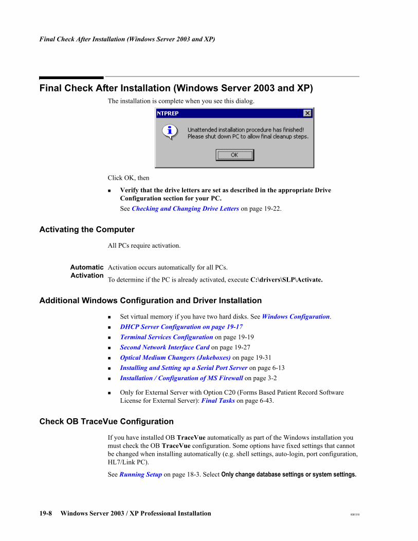
Final Check After Installation (Windows Server 2003 and XP)
19-8 Windows Server 2003 / XP Professional Installation 8081318
Final Check After Installation (Windows Server 2003 and XP)The installation is complete when you see this dialog.
Click OK, then
Verify that the drive letters are set as described in the appropriate Drive Configuration section for your PC.See Checking and Changing Drive Letters on page 19-22.
Activating the Computer
All PCs require activation.
AutomaticActivation
Activation occurs automatically for all PCs.
To determine if the PC is already activated, execute C:\drivers\SLP\Activate.
Additional Windows Configuration and Driver Installation
Set virtual memory if you have two hard disks. See Windows Configuration.DHCP Server Configuration on page 19-17Terminal Services Configuration on page 19-19Second Network Interface Card on page 19-27Optical Medium Changers (Jukeboxes) on page 19-31Installing and Setting up a Serial Port Server on page 6-13Installation / Configuration of MS Firewall on page 3-2
Only for External Server with Option C20 (Forms Based Patient Record Software License for External Server): Final Tasks on page 6-43.
Check OB TraceVue Configuration
If you have installed OB TraceVue automatically as part of the Windows installation you must check the OB TraceVue configuration. Some options have fixed settings that cannot be changed when installing automatically (e.g. shell settings, auto-login, port configuration, HL7/Link PC).
See Running Setup on page 18-3. Select Only change database settings or system settings.
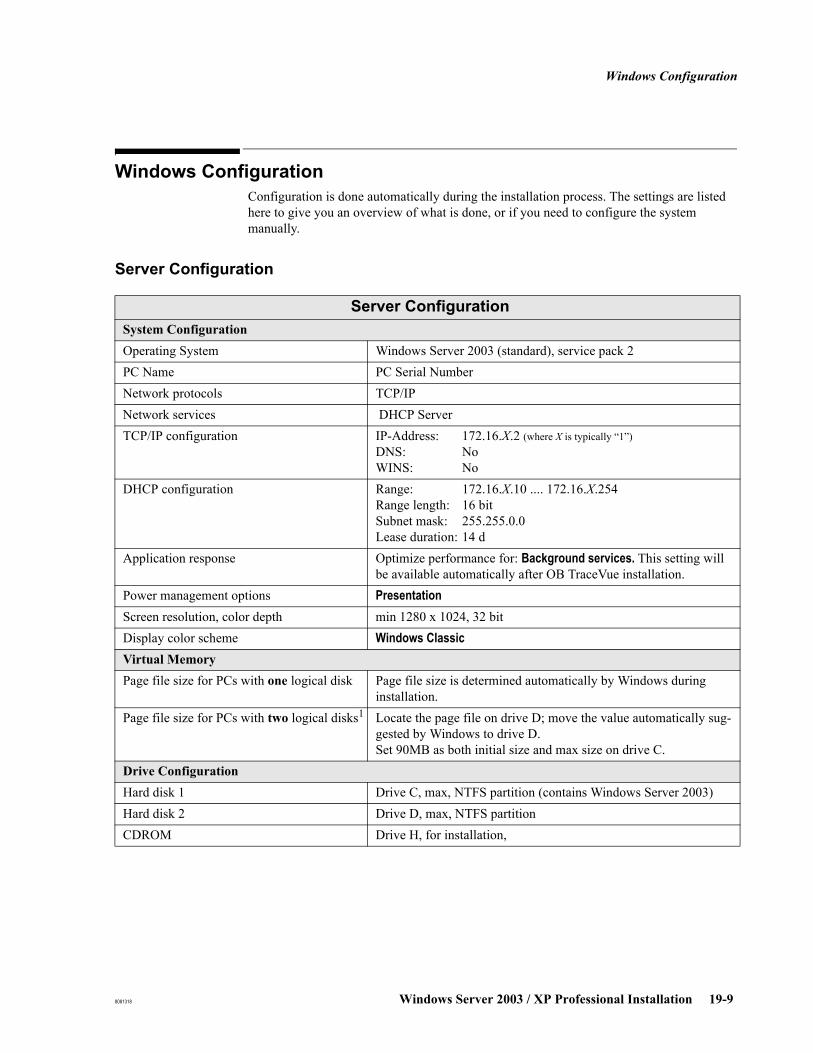
Windows Configuration
8081318 Windows Server 2003 / XP Professional Installation 19-9
Windows ConfigurationConfiguration is done automatically during the installation process. The settings are listed here to give you an overview of what is done, or if you need to configure the system manually.
Server Configuration
Server ConfigurationSystem ConfigurationOperating System Windows Server 2003 (standard), service pack 2PC Name PC Serial NumberNetwork protocols TCP/IPNetwork services DHCP ServerTCP/IP configuration IP-Address: 172.16.X.2 (where X is typically “1”)
DNS: NoWINS: No
DHCP configuration Range: 172.16.X.10 .... 172.16.X.254Range length: 16 bitSubnet mask: 255.255.0.0Lease duration: 14 d
Application response Optimize performance for: Background services. This setting will be available automatically after OB TraceVue installation.
Power management options PresentationScreen resolution, color depth min 1280 x 1024, 32 bitDisplay color scheme Windows ClassicVirtual MemoryPage file size for PCs with one logical disk Page file size is determined automatically by Windows during
installation.Page file size for PCs with two logical disks1 Locate the page file on drive D; move the value automatically sug-
gested by Windows to drive D.Set 90MB as both initial size and max size on drive C.
Drive ConfigurationHard disk 1 Drive C, max, NTFS partition (contains Windows Server 2003)Hard disk 2 Drive D, max, NTFS partitionCDROM Drive H, for installation,
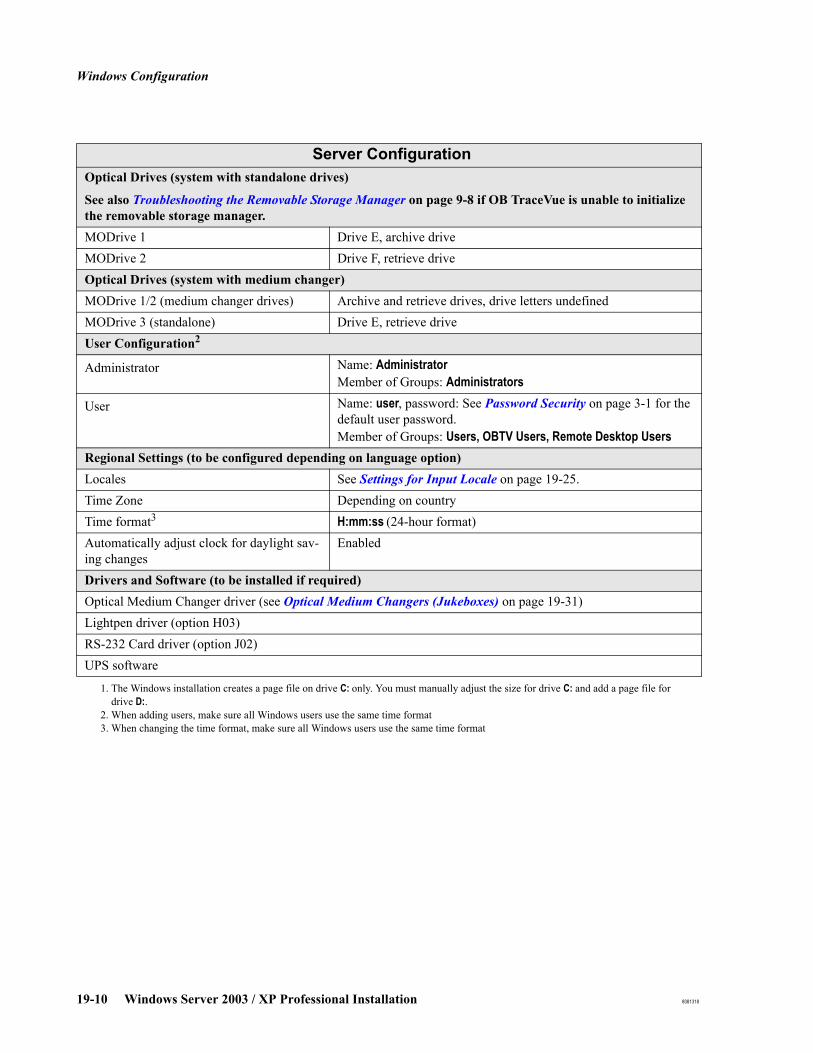
Windows Configuration
19-10 Windows Server 2003 / XP Professional Installation 8081318
Optical Drives (system with standalone drives)
See also Troubleshooting the Removable Storage Manager on page 9-8 if OB TraceVue is unable to initialize the removable storage manager.MODrive 1 Drive E, archive driveMODrive 2 Drive F, retrieve drive Optical Drives (system with medium changer)MODrive 1/2 (medium changer drives) Archive and retrieve drives, drive letters undefinedMODrive 3 (standalone) Drive E, retrieve driveUser Configuration2
Administrator Name: AdministratorMember of Groups: Administrators
User Name: user, password: See Password Security on page 3-1 for the default user password.Member of Groups: Users, OBTV Users, Remote Desktop Users
Regional Settings (to be configured depending on language option)Locales See Settings for Input Locale on page 19-25.Time Zone Depending on countryTime format3 H:mm:ss (24-hour format)Automatically adjust clock for daylight sav-ing changes
Enabled
Drivers and Software (to be installed if required)Optical Medium Changer driver (see Optical Medium Changers (Jukeboxes) on page 19-31)Lightpen driver (option H03)RS-232 Card driver (option J02)UPS software
1. The Windows installation creates a page file on drive C: only. You must manually adjust the size for drive C: and add a page file for drive D:.
2. When adding users, make sure all Windows users use the same time format3. When changing the time format, make sure all Windows users use the same time format
Server Configuration
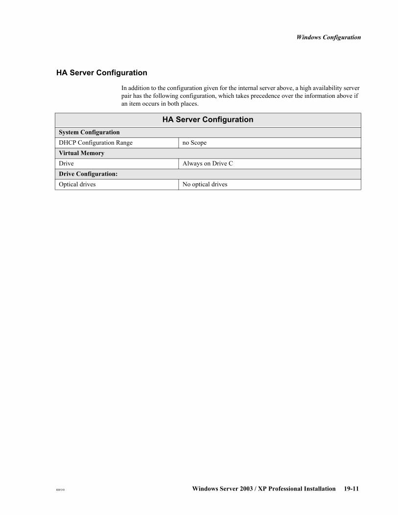
Windows Configuration
8081318 Windows Server 2003 / XP Professional Installation 19-11
HA Server Configuration
In addition to the configuration given for the internal server above, a high availability server pair has the following configuration, which takes precedence over the information above if an item occurs in both places.
HA Server ConfigurationSystem ConfigurationDHCP Configuration Range no ScopeVirtual MemoryDrive Always on Drive CDrive Configuration:Optical drives No optical drives

Windows Configuration
19-12 Windows Server 2003 / XP Professional Installation 8081318
External Database Server Configuration
External Database Server ConfigurationSystem ConfigurationOperating system Windows Server 2003 (standard), service pack 2PC Name PC Serial numberNetwork protocols TCP/IPNetwork services DHCP clientTCP/IP configuration DHCP client, all information provided by serverApplication response Optimize performance for: Background services. This setting will
be available automatically after OB TraceVue installation.Power management options PresentationDefault screen resolution, color depth 1280 x 1024, 32 bitDisplay color scheme Windows ClassicVirtual MemoryPage file size Page file size is automatically determined by Windows on installa-
tion.Drive Configuration:Hard disk 1 Drive C, max. NTFS partition (contains Windows Server 2003)CDROM Drive H, enabled.User Configuration1
1. When adding users, make sure all Windows users use the same time format
Administrator Name: AdministratorMember of Groups: Administrators
User Name: user, password: See Password Security on page 3-1 for the default user password.Member of Group: Users, OBTV Users, Remote Desktop Users
Regional Settings (to be configured depending on language option)Locales Settings for Input Locale on page 19-25.Time Zone Depending on country.Time format2
2. When changing the time format, make sure all Windows users use the same time format
H:mm:ss (24-hour format)Automatically adjust clock for daylight sav-ing changes
Enabled
Drivers & Software (to be installed if required)Lightpen driver (option H03)
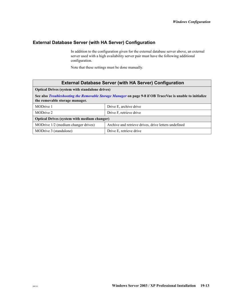
Windows Configuration
8081318 Windows Server 2003 / XP Professional Installation 19-13
External Database Server (with HA Server) Configuration
In addition to the configuration given for the external database server above, an external server used with a high availability server pair must have the following additional configuration.
Note that these settings must be done manually.
External Database Server (with HA Server) ConfigurationOptical Drives (system with standalone drives)
See also Troubleshooting the Removable Storage Manager on page 9-8 if OB TraceVue is unable to initialize the removable storage manager.MODrive 1 Drive E, archive driveMODrive 2 Drive F, retrieve driveOptical Drives (system with medium changer)MODrive 1/2 (medium changer drives) Archive and retrieve drives, drive letters undefinedMODrive 3 (standalone) Drive E, retrieve drive
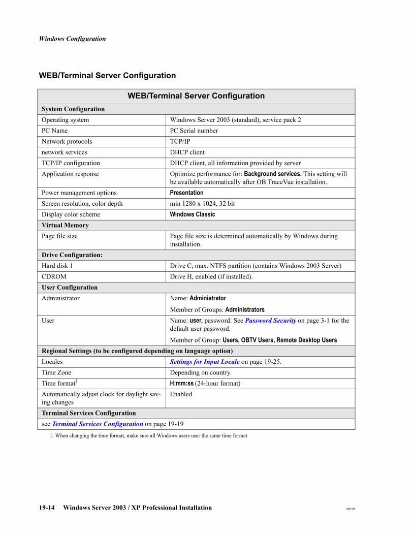
Windows Configuration
19-14 Windows Server 2003 / XP Professional Installation 8081318
WEB/Terminal Server Configuration
WEB/Terminal Server ConfigurationSystem ConfigurationOperating system Windows Server 2003 (standard), service pack 2PC Name PC Serial numberNetwork protocols TCP/IPnetwork services DHCP clientTCP/IP configuration DHCP client, all information provided by serverApplication response Optimize performance for: Background services. This setting will
be available automatically after OB TraceVue installation.Power management options PresentationScreen resolution, color depth min 1280 x 1024, 32 bitDisplay color scheme Windows ClassicVirtual MemoryPage file size Page file size is determined automatically by Windows during
installation.Drive Configuration:Hard disk 1 Drive C, max. NTFS partition (contains Windows 2003 Server)CDROM Drive H, enabled (if installed).User ConfigurationAdministrator Name: Administrator
Member of Groups: AdministratorsUser Name: user, password: See Password Security on page 3-1 for the
default user password.
Member of Group: Users, OBTV Users, Remote Desktop UsersRegional Settings (to be configured depending on language option)Locales Settings for Input Locale on page 19-25.Time Zone Depending on country.Time format1
1. When changing the time format, make sure all Windows users user the same time format
H:mm:ss (24-hour format)Automatically adjust clock for daylight sav-ing changes
Enabled
Terminal Services Configurationsee Terminal Services Configuration on page 19-19

Windows Configuration
8081318 Windows Server 2003 / XP Professional Installation 19-15
High End Data Acquisition Server Configuration
High End Data Acquisition Server ConfigurationSystem ConfigurationOperating system Windows Server 2003 (standard), service pack 2PC Name PC Serial numberNetwork protocols TCP/IPNetwork services DHCP clientTCP/IP configuration DHCP client, all information provided by serverApplication response Optimize performance for: Background services. This setting will
be available automatically after OB TraceVue installation.Power management options PresentationDefault screen resolution, color depth 1280 x 1024, 32 bitDisplay color scheme Windows ClassicVirtual MemoryPage file size Page file size is automatically determined by Windows on installa-
tion.Drive Configuration:Hard disk 1 Drive C, max. NTFS partition (contains Windows Server 2003)CDROM Drive H, enabled.User Configuration1
1. When adding users, make sure all Windows users use the same time format
Administrator Name: AdministratorMember of Groups: Administrators
User Name: user, password: See Password Security on page 3-1 for the default user password.Member of Group: Users, OBTV Users, Remote Desktop Users
Regional Settings (to be configured depending on language option)Locales Settings for Input Locale on page 19-25.Time Zone Depending on country.Time format2
2. When changing the time format, make sure all Windows users use the same time format
H:mm:ss (24-hour format)Automatically adjust clock for daylight sav-ing changes
Enabled
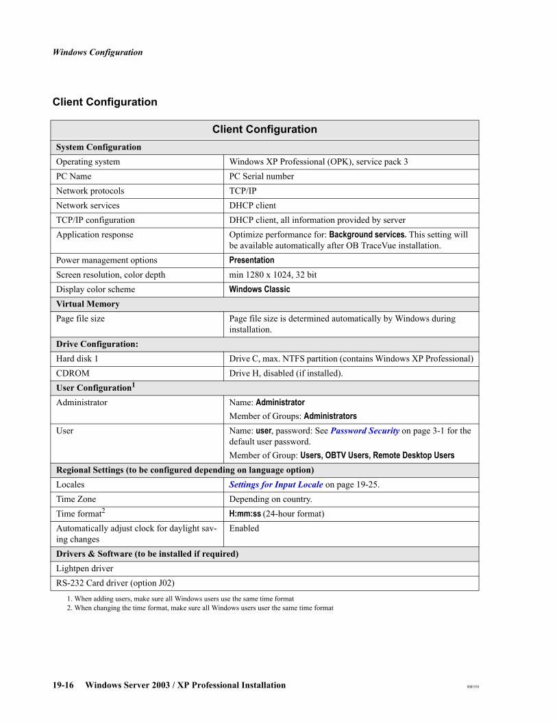
Windows Configuration
19-16 Windows Server 2003 / XP Professional Installation 8081318
Client Configuration
Client ConfigurationSystem ConfigurationOperating system Windows XP Professional (OPK), service pack 3PC Name PC Serial numberNetwork protocols TCP/IPNetwork services DHCP clientTCP/IP configuration DHCP client, all information provided by serverApplication response Optimize performance for: Background services. This setting will
be available automatically after OB TraceVue installation.Power management options PresentationScreen resolution, color depth min 1280 x 1024, 32 bitDisplay color scheme Windows ClassicVirtual MemoryPage file size Page file size is determined automatically by Windows during
installation.Drive Configuration:Hard disk 1 Drive C, max. NTFS partition (contains Windows XP Professional)CDROM Drive H, disabled (if installed).User Configuration1
1. When adding users, make sure all Windows users use the same time format
Administrator Name: AdministratorMember of Groups: Administrators
User Name: user, password: See Password Security on page 3-1 for the default user password.Member of Group: Users, OBTV Users, Remote Desktop Users
Regional Settings (to be configured depending on language option)Locales Settings for Input Locale on page 19-25.Time Zone Depending on country.Time format2
2. When changing the time format, make sure all Windows users user the same time format
H:mm:ss (24-hour format)Automatically adjust clock for daylight sav-ing changes
Enabled
Drivers & Software (to be installed if required)Lightpen driverRS-232 Card driver (option J02)
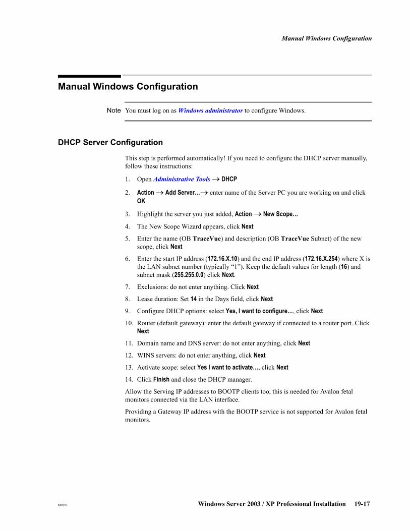
Manual Windows Configuration
8081318 Windows Server 2003 / XP Professional Installation 19-17
Manual Windows Configuration
Note You must log on as Windows administrator to configure Windows.
DHCP Server Configuration
This step is performed automatically! If you need to configure the DHCP server manually, follow these instructions:
1. Open Administrative Tools → DHCP
2. Action → Add Server…→ enter name of the Server PC you are working on and click OK
3. Highlight the server you just added, Action → New Scope…
4. The New Scope Wizard appears, click Next
5. Enter the name (OB TraceVue) and description (OB TraceVue Subnet) of the new scope, click Next
6. Enter the start IP address (172.16.X.10) and the end IP address (172.16.X.254) where X is the LAN subnet number (typically “1”). Keep the default values for length (16) and subnet mask (255.255.0.0) click Next.
7. Exclusions: do not enter anything. Click Next
8. Lease duration: Set 14 in the Days field, click Next
9. Configure DHCP options: select Yes, I want to configure…, click Next
10. Router (default gateway): enter the default gateway if connected to a router port. Click Next
11. Domain name and DNS server: do not enter anything, click Next
12. WINS servers: do not enter anything, click Next
13. Activate scope: select Yes I want to activate…, click Next
14. Click Finish and close the DHCP manager.
Allow the Serving IP addresses to BOOTP clients too, this is needed for Avalon fetal monitors connected via the LAN interface.
Providing a Gateway IP address with the BOOTP service is not supported for Avalon fetal monitors.

Manual Windows Configuration
19-18 Windows Server 2003 / XP Professional Installation 8081318
Fast User Switching
It is not permitted to enable fast user switching. It is disabled by default. These settings are not available for PCs integrated into a domain.
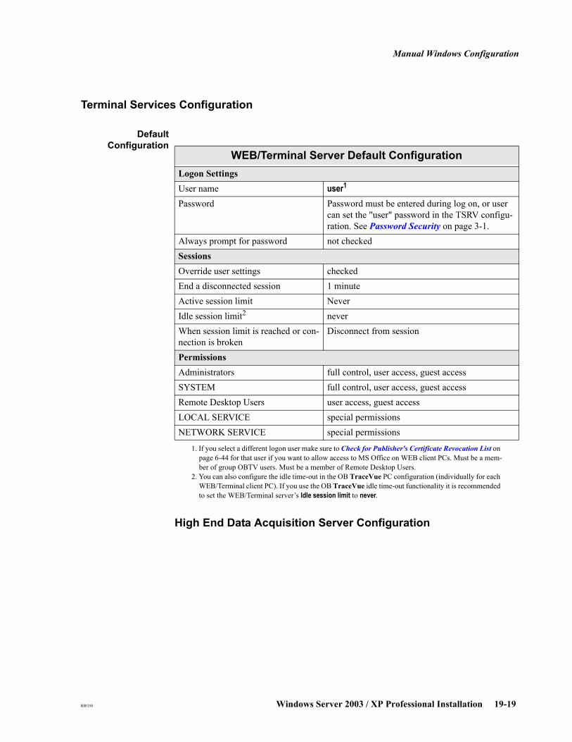
Manual Windows Configuration
8081318 Windows Server 2003 / XP Professional Installation 19-19
Terminal Services Configuration
DefaultConfiguration
WEB/Terminal Server Default ConfigurationLogon SettingsUser name user1
1. If you select a different logon user make sure to Check for Publisher's Certificate Revocation List on page 6-44 for that user if you want to allow access to MS Office on WEB client PCs. Must be a mem-ber of group OBTV users. Must be a member of Remote Desktop Users.
Password Password must be entered during log on, or user can set the "user" password in the TSRV configu-ration. See Password Security on page 3-1.
Always prompt for password not checkedSessionsOverride user settings checkedEnd a disconnected session 1 minuteActive session limit NeverIdle session limit2
2. You can also configure the idle time-out in the OB TraceVue PC configuration (individually for each WEB/Terminal client PC). If you use the OB TraceVue idle time-out functionality it is recommended to set the WEB/Terminal server’s Idle session limit to never.
High End Data Acquisition Server Configuration
neverWhen session limit is reached or con-nection is broken
Disconnect from session
PermissionsAdministrators full control, user access, guest accessSYSTEM full control, user access, guest accessRemote Desktop Users user access, guest accessLOCAL SERVICE special permissionsNETWORK SERVICE special permissions
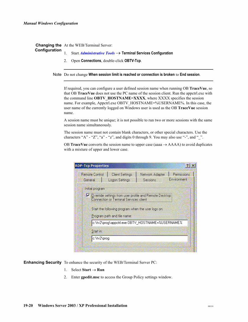
Manual Windows Configuration
19-20 Windows Server 2003 / XP Professional Installation 8081318
Changing theConfiguration
At the WEB/Terminal Server:
1. Start Administrative Tools → Terminal Services Configuration
2. Open Connections, double-click OBTV-Tcp.
Note Do not change When session limit is reached or connection is broken to End session.
If required, you can configure a user defined session name when running OB TraceVue, so that OB TraceVue does not use the PC name of the session client. Run the appctrl.exe with the command line OBTV_HOSTNAME=XXXX, where XXXX specifies the session name. For example, Appctrl.exe OBTV_HOSTNAME=%USERNAME%. In this case, the user name of the currently logged on Windows user is used as the OB TraceVue session name.
A session name must be unique; it is not possible to run two or more sessions with the same session name simultaneously.
The session name must not contain blank characters, or other special characters. Use the characters “A” - “Z”, “a” - “z”, and digits 0 through 9. You may also use “-”, and “_”.
OB TraceVue converts the session name to upper case (aaaa → AAAA) to avoid duplicates with a mixture of upper and lower case.
Enhancing Security To enhance the security of the WEB/Terminal Server PC:
1. Select Start → Run
2. Enter gpedit.msc to access the Group Policy settings window.

Manual Windows Configuration
8081318 Windows Server 2003 / XP Professional Installation 19-21
3. In the Group Policy settings window:
a. Select User Configuration.
b. Select Administrative Templates.
c. Select System.
d. Select Ctrl+Alt+Delete options.
e. Select Remove Task Manager.
f. Double-click the Remove Task Manager option.
g. Select Enabled.

Manual Windows Configuration
19-22 Windows Server 2003 / XP Professional Installation 8081318
Checking and Changing Drive LettersWhen installing Windows or when replacing harddisks, CD-ROM drives, or optical drives Windows automatically assigns drives letters. The drive letters may not match the OB TraceVue requirements.
Refer to the configuration table for the appropriate PC (section Drive configuration):Server Configuration on page 19-9HA Server Configuration on page 19-11External Database Server Configuration on page 19-12WEB/Terminal Server Configuration on page 19-14Client Configuration on page 19-16
If you need to change drive letters:
1. Start Disk Management.2. Right-click a drive, select Change Drive Letter and Path.3. Click Edit to assign the new drive letter.
Time Zone
Double-click on the displayed time on the toolbar and select the tab time zone.
1. Select your Time Zone in the drop down list box.
2. Select the date / time tab and set the current time and date.
3. Make sure the automatically adjust daylight saving flag is enabled on all PCs. Exit with OK.
Manual Windows Configuration
8081318 Windows Server 2003 / XP Professional Installation 19-23
Windows Time Service
OB TraceVue’s time can be set using the Windows time service. This means that daylight savings time changes are handled automatically and you do not have to program them manually.
The time service sets the time on the internal server. All PCs take their time from the internal server automatically. The time difference between the time server and the internal server must be less than 12 hours. If it is not, change the internal server manually.
The time server PC can be either the IP address of the time server or the name of the time server PC itself.
If an external time server is being used for a high availability pair, make sure that both nodes are connected to the same time source.
If integrated into the domain, the domain controller is the time server and no further steps are necessary.
Setting TimeSynchronization
Automatically
The internal server PC must be connected to the timer server PC (TSPC) using the Windows Time Service (w32time). Automatically adjust clock for daylight saving changes must be enabled on all PCs.
1. At the internal server, login as Administrator.
2. Double click the system clock.
3. Select the tab "Internet Time".
4. Enter the qualified time server name or IP address (if name resolution is not available).
5. Press apply, then press update now to test the time service functionality.
6. Below the update now button, the following message should appear:
"The time has been successfully synchronized with [Timeserver] on [Date] at [Time]"
If a time server has been specified for the internal server, then all other PCs in the OB TraceVue system must have either no time server specified or the same time server as the internal server.
Setting TimeSynchronization
Manually
To synchronize the time immediately, without waiting for an automatic synchronization:
1. At the internal server, login as Administrator.
2. Double click the system clock.
3. Select the tab "Internet Time".
4. Press update now.
5. Below the update now button, the following message should appear:
"The time has been successfully synchronized with [Timeserver] on [Date] at [Time]"
Changing the Time If a time server has been specified for the internal server, or for the OB TraceVue system then the time must be corrected on the time server.

Manual Windows Configuration
19-24 Windows Server 2003 / XP Professional Installation 8081318

Manual Windows Configuration
8081318 Windows Server 2003 / XP Professional Installation 19-25
Regional Settings
When installing OB TraceVue, the appropriate regional settings are applied automatically, depending on the ordered language option. However, if you need to apply these manually:
1. In the Control Panel select Regional Options.
2. General:
a. Select Your locale (location) for which the system is ordered. This setting applies to the way the numbers, times, date and currency are displayed. It is independent of the OB TraceVue language.
b. Language settings for the system: select the languages the operating system must support.
c. Click the Set default... button. In the dialog select the default system locale. The default system locale must match the language of OB TraceVue. This setting ensures that the correct code page and fonts are used by OB TraceVue.
3. Input Locales: This setting applies to the input language and keyboard layout and Input Method Editor (IME)
a. In the Add Input Locale dialog, select the input locale from the table below, based on ordered localization option and close the window.
b. Select the locale that was just added and click Set as Default to make this the default input locale for this system.
Settings for InputLocale OB TraceVue
language settingUser Locale
System LocaleInput Language
Keyboard Layout / IME
English English (US) English (Unites States) - US
Troubleshooting Windows Server 2003 / XP Professional Installation
19-26 Windows Server 2003 / XP Professional Installation 8081318
Troubleshooting Windows Server 2003 / XP Professional Installation
Windows 2003 Works but Final Message Box Does Not Appear
If Windows Server 2003 or XP Professional seem to be installed, but
the PC appears to do nothing for more than five minutes and the final message box saying that the installation procedure has finished has not yet appeared
reboot the PC. This will solve the problem in most cases and the installation procedure will continue automatically.
If this does not help, open the Explorer and start the file C:\CONFIG\NTPREP.EXE on the local hard disk. This file starts the automatic Windows 2003 configuration for your installation. Wait until the final message box appears (the PC will reboot several times).
The directory C:\CONFIG is deleted automatically when you reboot after the successful installation and configuration of Windows Server 2003 / XP Professional.
After installation, check the configuration as described in Windows Configuration on page 19-9.
Unable to Boot PC or Install Windows Server 2003 / XP Professional
In case of severe BIOS problems (POST errors) clear the CMOS memory and load the default BIOS configuration.
Refer to the User’s Guide for the PC for details of how to access the system board switches, and which switch is used to clear the CMOS.
The procedure is summarized below:
1. Shutdown and power down the PC. Unplug the power cord, remove the PC cover.
2. Set the according system board switch to clear the CMOS.
3. Refit the cover, and reconnect only the power cable.
4. Switch on the PC. This erases the CMOS memory. A message will be displayed.
5. Switch off the PC, disconnect the power cable, and remove the cover.
6. Set the system board switch to retain the CMOS.
7. Refit the PC's power supply and the PC cover, and reconnect the power cable and LAN connection.
8. Switch on the PC. It displays an error message.
9. Run BIOS setup. Default values are automatically loaded.
10. When you are satisfied that the BIOS settings are as required (see BIOS sections in the appropriate PC chapter) save the configuration and exit from BIOS setup.
Component Installation
8081318 Windows Server 2003 / XP Professional Installation 19-27
Component Installation
Second Network Interface Card
A second NIC must not be installed in either the internal server PC, or the external server PC. It is permitted only at a client PC, and a WEB/TS server.
Note See also Integration Guide, chapter Network Guide
Caution: Two network cards of a single PC must not be connected to a single physical subnet (must not be in a single broadcast domain) for the configuration used with OB TraceVue. That means you must not plug two NICs of a single PC into the same switch. Failure to do so will cause booting problems and errors with certain protocols.
Overview To install a second network interface card (NIC) you must perform the following tasks:
1. Shut down the PC.
2. Install the second NIC. Do not connect the LAN cable.
3. Power-up the PC. Log in as Windows administrator.
4. Windows automatically detects and installs the necessary drivers.
5. After the automatic installation is complete, check the NIC assignment.
6. Configure the second NIC.
7. Connect the LAN cable.
NIC Assignment The first NIC is always the onboard NIC and named as OBTV LAN.
Caution: Upgrade of a system with a second NIC may change NIC assignment.
Component Installation
19-28 Windows Server 2003 / XP Professional Installation 8081318
NIC Configuration You can access the properties of the network interface cards in Control Panel → Network and Dial-up Connections. The first network card that is used and pre-configured for the internal connection within an OB TraceVue system is normally named OBTV LAN. An additionally installed NIC is called Local Area Connection 2. Perform the following configuration steps for the additional NIC:
1. Rename Network Connections
For better identification of the two network cards you should rename them in the Network and Dial-up Connection view.
OBTV LAN should be named Internal Connection.Local Area Connection 2 should be named External Connection.
2. Label Network Interface Cards on PC Housing
For easier assignment of the NICs installed in the PC you should label the connector on the back of the PC according to NIC Assignment on page 19-27. You can verify the correct labeling by connecting and disconnecting the NICs to the OB TraceVue network and view the status of the connection in the Network and Dial-up Connection view.
3. Configure TCP/IP Protocol
Get TCP/IP configuration settings from the hospital IT department. It is recommended to use a static IP address for the second NIC. Update the Installation Checklist for the PC according to the settings used.
TCP/IP configuration is performed in Network and Dial-up Connection → <Name of External Connection> → Properties → Internet Protocol (TCP/IP) → Properties.
Note The first two components of the IP address for the second network card must not be identical to the first two components of the IP address for the first network card (the network address must be different).
Type of Hospital Network TCP/IP ConfigurationHospital with own IP address range: Use hospital network infrastructure for connections.
Get the TCP/IP configuration settings from local IT department. It is recommended to use a static IP address for the second NIC.
A hospital without own IP address range wants to connect multiple OB TraceVue systems with OB Trace-Vue Link.
Only external server PC has a second NIC.
Use a dedicated switch to connect OB TraceVue systems.
Assign IP address to second NIC of external server as follows:
172.17.1.2 (first OB TraceVue system)
172.17.1.3 (second OB TraceVue system)
172.17.1.4 (third system....and so on.)
Subnet Mask: 255.255.0.0 (all each systems)
Default Gateway: not used

Component Installation
8081318 Windows Server 2003 / XP Professional Installation 19-29
4. Enable Network Connections
In the Network and Dial-up Connection view, select the connection and choose Enable from the file menu.
5. Connect the second NIC to the hospital network.

Component Installation
19-30 Windows Server 2003 / XP Professional Installation 8081318
Light Pen PXL 595 (PCI)
Note dc7600 and later PCs do not support light pens.
If you need to manually reinstall the light pen driver:1. Start the Device Manager.
2. Open Mice and other pointing device.
3. Double click PCI Input Device (marked with a yellow exclamation mark).
4. Select the tab Driver.
5. Click the Update button.
6. Select the driver from the local disks and specify the following directory:C:\DRIVERS\LPN595
7. Click Yes to accept the missing signature.
8. After next reboot, you must calibrate the light pen.
Additional RS-232 Interface Card (J02)
A new PC with PCI RS-232 I/F card, requires the plug and play PCI RS-232 driver. This is installed automatically during Windows Server 2003 / XP Professional setup.
Manual procedure to install the driver:
Windows Server 2003 / XP Professional automatically selects the required files and installs the device.
SCSI Host Adapter
Windows Server 2003 / XP Professional detects the new hardware automatically and installs the correct driver without user interaction.
Component Installation
8081318 Windows Server 2003 / XP Professional Installation 19-31
Optical Medium Changers (Jukeboxes)
The HP and Plasmon jukeboxes have different installation procedures.
HP Sure Store 1. Connect the medium changer, turn the power on.
2. Power up / reboot the PC. Log in as Windows administrator.
Windows automatically detects and installs the necessary driver (HP Sure Store Optical Library).
Plasmon 1. Connect the medium changer, turn the power on.
2. Power up / reboot the PC. Log in as Windows administrator.
3. Open the Device Manager
4. Select Medium Changers.
5. Right click Unknown Medium Changer Device and select Properties.
6. On the Driver page, click Update Driver...
7. The Wizard starts; on the first page select No, not this time and click Next.
8. Select Install from a list or specific location (Advanced) and click Next.
9. Select Don’t search. I will choose the driver to install and click Next.
10. Click on have a disk.
11. Enter the following directory C:\DRIVERS\Plasmon and click OK.
12. Select Plasmon Medium Changer.
13. Click Next to start the device installation.
14. Click Finish to end the installation.
15. Close the Properties box.
16. Close the Device Manager.
17. Continue installation of optical Medium changer see OB TraceVue Setup on page 18-2.
ELO Touchscreen
1. Start C:\Drivers\Elotouch\setup.cmd
the setup runs unattended until calibration is necessary.manually set the desired display settings
2. Hit the targets using the soft pen when requested.
Component Installation
19-32 Windows Server 2003 / XP Professional Installation 8081318
UPS Software
The software is installed and configured automatically during the OB TraceVue Windows installation.
The software is not installed and configured on upgrade PCs; you must do this manually.
If you need to manually install the driver connect the UPS to the PC and follow the procedures below. See also UPS on page 13-22.
Smart SolutionInstallation (APC
Smart-UPS 1000)
1. Connect the serial interface of the UPS to a free COM port of your PC and switch it on.
2. Execute the program C:\Drivers\PCPlus52\setup.exe and make the following selections:
Select Continue with installation now.Select Yes to accept the software license agreement
Select Typical installation.
Select Yes to let the setup program select automatically the correct COM port.
Enable PowerChute plus remote monitoring
3. Copy the .ini1 file either from the HDD (C:\Drivers\PCPlus52) or from the server CD (H:\Drivers\PCPlus52) to the directory C:\Program files\PwrChute.
4. Restart the computer to activate the PowerChute software.
Simple SolutionInstallation (APCBack-UPS / Smart-
UPS 620/1000)
Client PC only: run OB TraceVue setup to free up COM1.
Open Control Panel, select Power Options.
Select the UPS tab, click the Select… button.
Select American Power Conversion from the Select manufacturer: combo box.
Model: Back UPS is connected: Back-UPSSmart UPS 620/1000 is connected: Smart-UPS
Click Finish, click Configure… Settings:
Enable all notifications: uncheckedMinutes on battery before critical alarm: checked value: 8 When the alarm occurs, run this program: uncheckedNext, instruct the computer to: ShutdownSmart UPS 620/1000 only: Finally turn off the UPS: checked
Commit the new settings.
1. Internal Server PC: pwrchute.iniHigh-end External Server PC: pwrchut2.iniHigh-end Web/Terminal Server PC: pwrchut2.iniHigh-end Data Acquisition Server PC pwrchut2.iniHigh Availability Server PC pwrchut3.ini
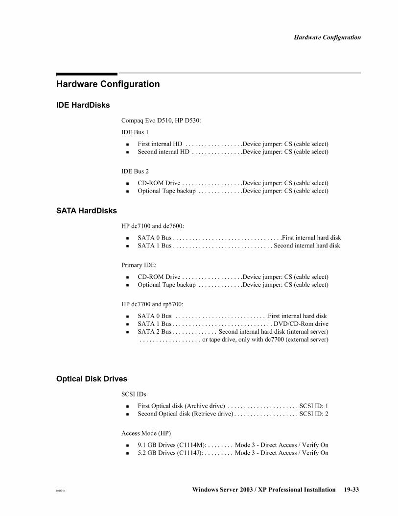
Hardware Configuration
8081318 Windows Server 2003 / XP Professional Installation 19-33
Hardware Configuration
IDE HardDisks
Compaq Evo D510, HP D530:
IDE Bus 1
First internal HD . . . . . . . . . . . . . . . . . .Device jumper: CS (cable select)Second internal HD . . . . . . . . . . . . . . . .Device jumper: CS (cable select)
IDE Bus 2
CD-ROM Drive . . . . . . . . . . . . . . . . . . .Device jumper: CS (cable select)Optional Tape backup . . . . . . . . . . . . . .Device jumper: CS (cable select)
SATA HardDisks
HP dc7100 and dc7600:
SATA 0 Bus . . . . . . . . . . . . . . . . . . . . . . . . . . . . . . . . . .First internal hard disk SATA 1 Bus . . . . . . . . . . . . . . . . . . . . . . . . . . . . . . . Second internal hard disk
Primary IDE:
CD-ROM Drive . . . . . . . . . . . . . . . . . . .Device jumper: CS (cable select)Optional Tape backup . . . . . . . . . . . . . .Device jumper: CS (cable select)
HP dc7700 and rp5700:
SATA 0 Bus . . . . . . . . . . . . . . . . . . . . . . . . . . . . .First internal hard disk SATA 1 Bus . . . . . . . . . . . . . . . . . . . . . . . . . . . . . . . DVD/CD-Rom driveSATA 2 Bus . . . . . . . . . . . . . . Second internal hard disk (internal server) . . . . . . . . . . . . . . . . . . . or tape drive, only with dc7700 (external server)
Optical Disk Drives
SCSI IDs
First Optical disk (Archive drive) . . . . . . . . . . . . . . . . . . . . . . SCSI ID: 1Second Optical disk (Retrieve drive) . . . . . . . . . . . . . . . . . . . . SCSI ID: 2
Access Mode (HP)
9.1 GB Drives (C1114M): . . . . . . . . Mode 3 - Direct Access / Verify On5.2 GB Drives (C1114J): . . . . . . . . . Mode 3 - Direct Access / Verify On
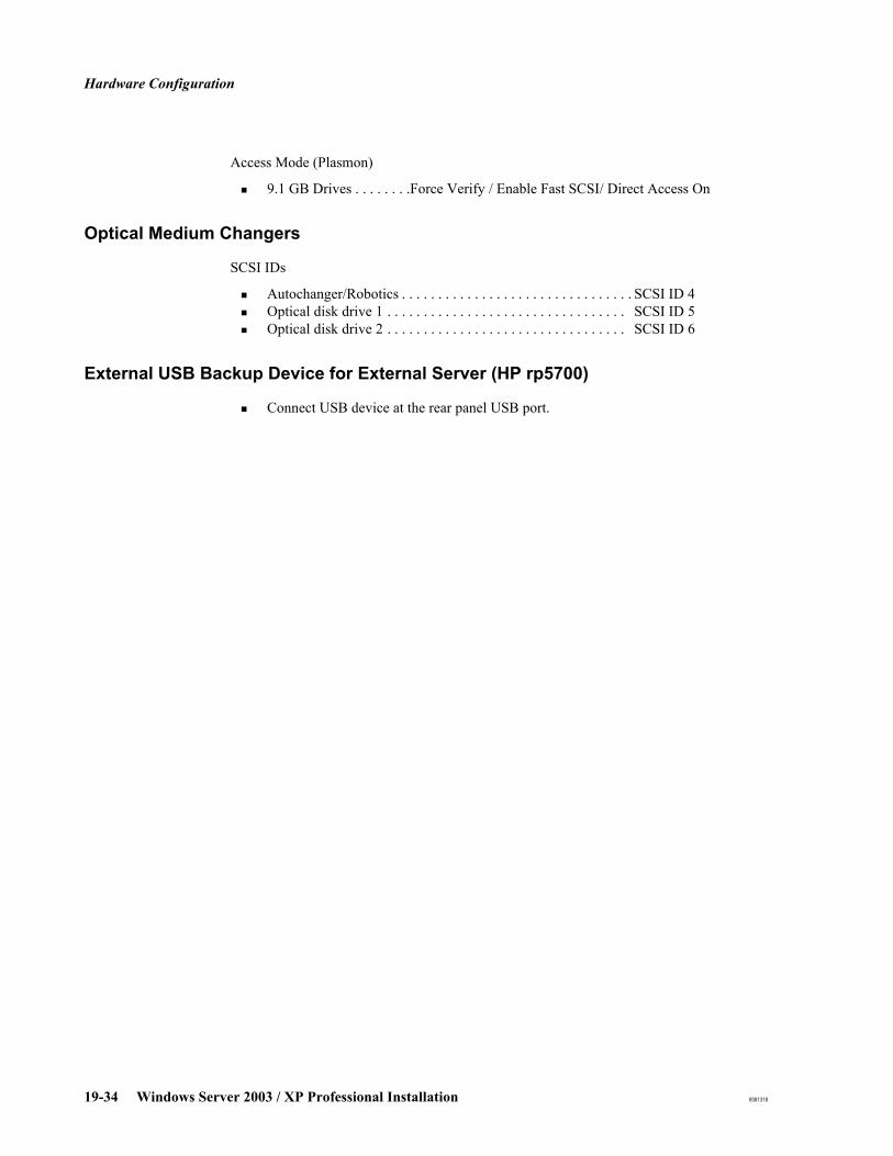
Hardware Configuration
19-34 Windows Server 2003 / XP Professional Installation 8081318
Access Mode (Plasmon)
9.1 GB Drives . . . . . . . .Force Verify / Enable Fast SCSI/ Direct Access On
Optical Medium Changers
SCSI IDs
Autochanger/Robotics . . . . . . . . . . . . . . . . . . . . . . . . . . . . . . . . SCSI ID 4Optical disk drive 1 . . . . . . . . . . . . . . . . . . . . . . . . . . . . . . . . . SCSI ID 5Optical disk drive 2 . . . . . . . . . . . . . . . . . . . . . . . . . . . . . . . . . SCSI ID 6
External USB Backup Device for External Server (HP rp5700)
Connect USB device at the rear panel USB port.
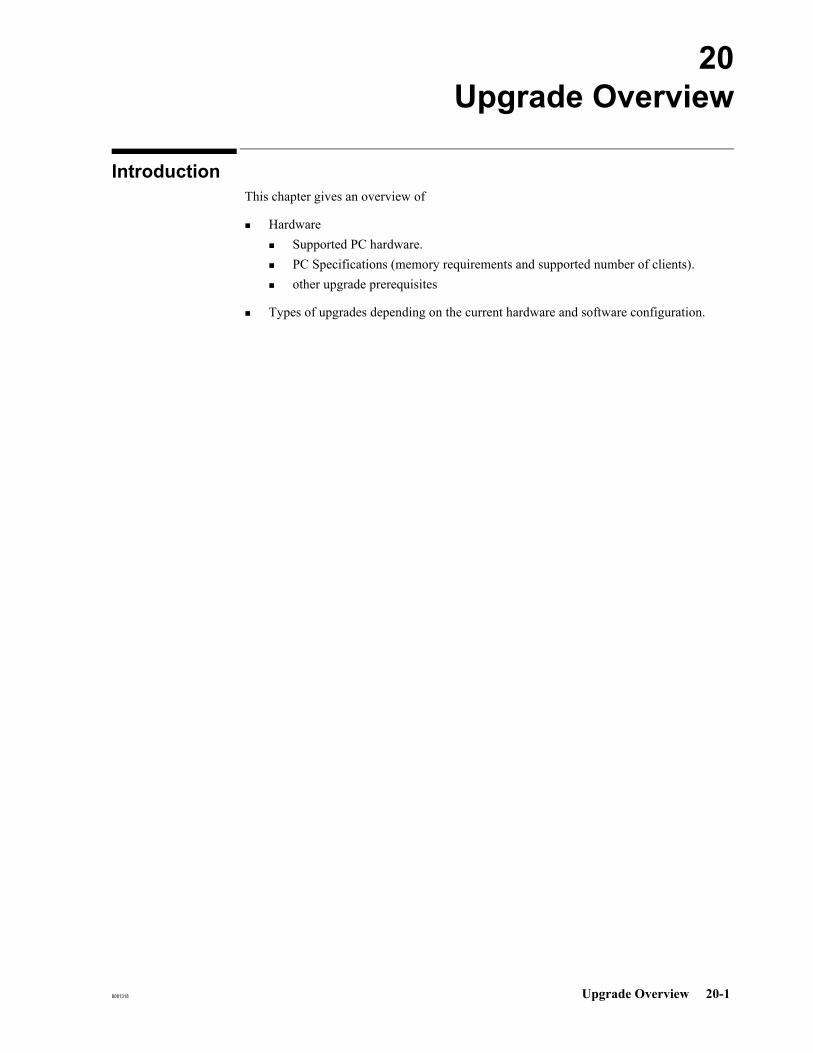
8081318 Upgrade Overview 20-1
20Upgrade Overview
IntroductionThis chapter gives an overview of
HardwareSupported PC hardware.PC Specifications (memory requirements and supported number of clients).other upgrade prerequisites
Types of upgrades depending on the current hardware and software configuration.

Hardware
20-2 Upgrade Overview 8081318
Hardware
Supported PCs
The following table lists the supported OB TraceVue PC hardware.
Existing PC’s can be reused if the appropriate column is checked. RAID-5 PCs (ML370x and ML 350x) must be upgraded to RAID-1.For memory requirements and supported number of clients also refer to Memory Requirements on page 20-3. The type of upgrade required is described in Upgrade Types on page 20-10.
Table 20-1 Supported PCs 1
PC Hardware
Server PCs Client PCs
Seri
al P
ort S
erve
r H
ost
Eco
nom
ic In
tern
al
Hig
h Av
aila
bilit
yPa
ir
Inte
rnal
Ext
erna
l
WE
B/T
erm
inal
CIE
Clie
nt
Clie
nt
Evo D510 (M3167-60003)D530 (M3167C, M3167D)dc7100 (M3167E)dc7600 (M3167F, M3167G)dc7700 rp5700
- -
rp 5700 (as economic internal server ) - - - - - -
ML370 G2 (RAID-1)ML370 G3 (M3168B, M3168C) (RAID-1)
- - - - - -
ML370 G3 (M3168D) (RAID-1) - - - - -ML350 G4 (RAID-1)ML350 G4p (RAID-1)ML350 G5 (RAID-1)
- - - -
1. The standalone MO drive may be operated only in a horizontal plane.

Hardware
8081318 Upgrade Overview 20-3
PC Specifications
MemoryRequirements
Memory Requirements The tables describe the minimum memory required for OB TraceVue.
Purchase required memory upgrades locally. You may have to discard existing memory. Use only memory upgrades that are tested and supported.
The requirements for upgrading the memory in a PC are:Total memory must be at least as specified in the table below.PC memory must be recognized at bootup with no errors.
Maximum Numberof Clients Per
System
The maximum number of clients in an OB TraceVue system is determined by which ever server (internal or external) has the lower performance specification.
For example, if a dc 7700 internal server is coupled with an ML 350 external server, only 30 clients are supported. However, if an ML 350 G5 internal server is coupled with and ML 350 external server, 150 clients are supported.
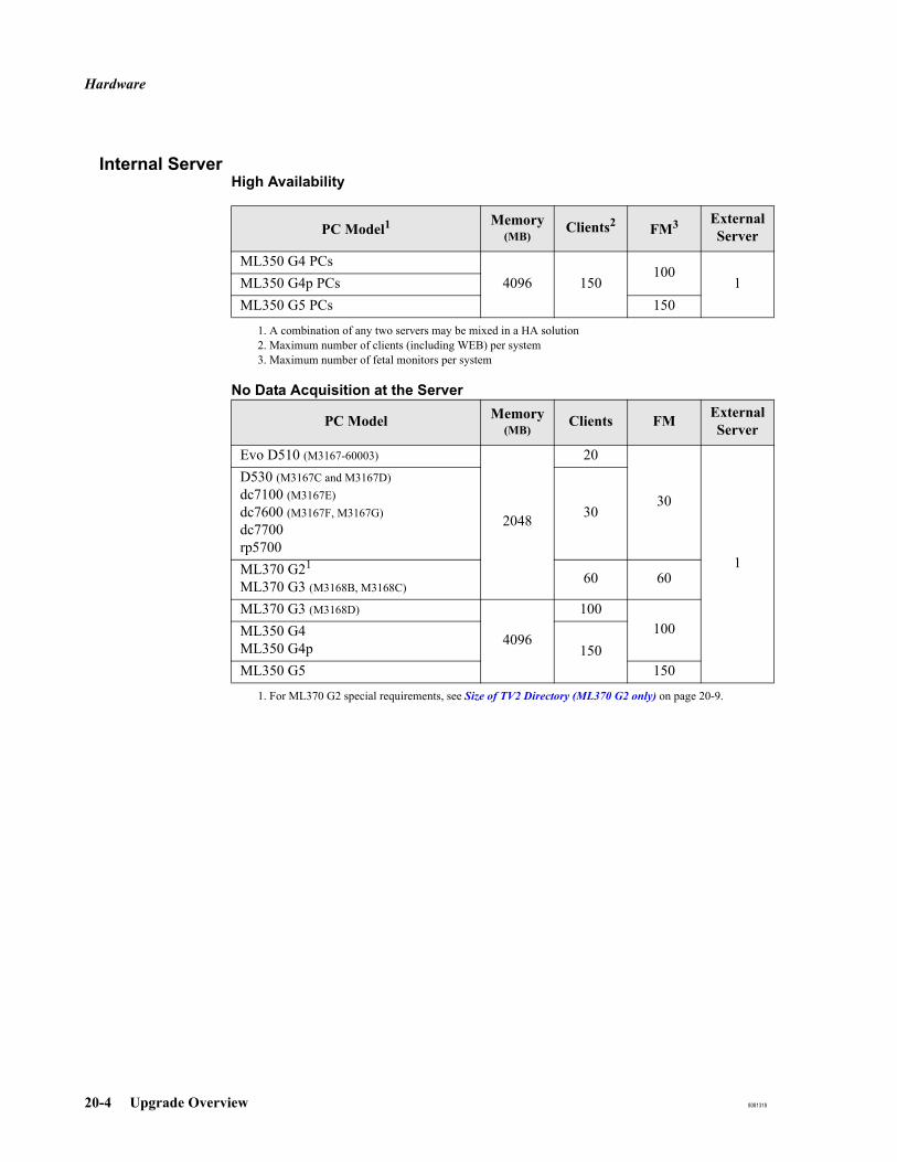
Hardware
20-4 Upgrade Overview 8081318
Internal ServerHigh Availability
No Data Acquisition at the Server
PC Model1
1. A combination of any two servers may be mixed in a HA solution
Memory (MB)
Clients2
2. Maximum number of clients (including WEB) per system
FM3
3. Maximum number of fetal monitors per system
External Server
ML350 G4 PCs4096 150
1001ML350 G4p PCs
ML350 G5 PCs 150
PC Model Memory (MB)
Clients FM External Server
Evo D510 (M3167-60003)
2048
20
30
1
D530 (M3167C and M3167D)dc7100 (M3167E)dc7600 (M3167F, M3167G)dc7700rp5700
30
ML370 G21
ML370 G3 (M3168B, M3168C)
1. For ML370 G2 special requirements, see Size of TV2 Directory (ML370 G2 only) on page 20-9.
60 60
ML370 G3 (M3168D)
4096
100100ML350 G4
ML350 G4p 150ML350 G5 150
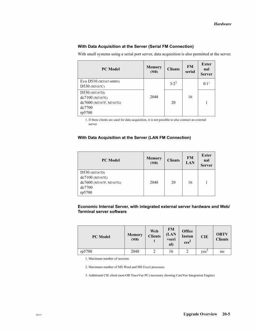
Hardware
8081318 Upgrade Overview 20-5
With Data Acquisition at the Server (Serial FM Connection)
With small systems using a serial port server, data acquisition is also permitted at the server.
With Data Acquisition at the Server (LAN FM Connection)
Economic Internal Server, with integrated external server hardware and Web/Terminal server software
PC Model Memory (MB)
Clients FMserial
External
Server
Evo D510 (M3167-60003)D530 (M3167C)
2048
3/21
1. If three clients are used for data acquisition, it is not possible to also connect an external server.
16
0/11
D530 (M3167D)dc7100 (M3167E)dc7600 (M3167F, M3167G)dc7700rp5700
20 1
PC Model Memory (MB)
Clients FM LAN
External
Server
D530 (M3167D)dc7100 (M3167E)dc7600 (M3167F, M3167G)dc7700rp5700
2048 20 16 1
PC Model Memory (MB)
Web Clients
1
1. Maximum number of sessions
FM (LAN+seri
al)
Office Instan
ces2
2. Maximum number of MS Word and MS Excel processes
CIE OBTVClients
rp5700 2048 2 16 2 yes3
3. Additional CIE client (non-OB TraceVue PC) necessary (hosting CareVue Integration Engine)
no
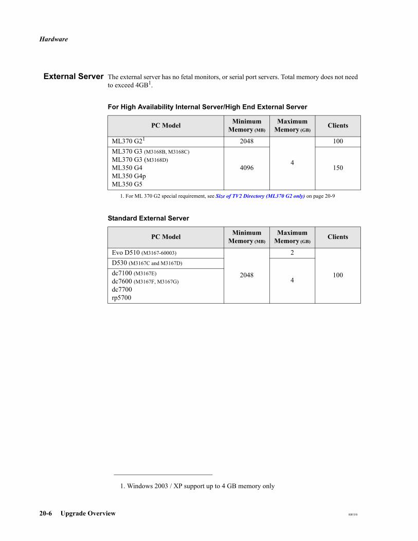
Hardware
20-6 Upgrade Overview 8081318
External Server The external server has no fetal monitors, or serial port servers. Total memory does not need to exceed 4GB1.
For High Availability Internal Server/High End External Server
Standard External Server
1. Windows 2003 / XP support up to 4 GB memory only
PC Model Minimum Memory (MB)
Maximum Memory (GB)
Clients
ML370 G21
1. For ML 370 G2 special requirement, see Size of TV2 Directory (ML370 G2 only) on page 20-9
2048
4
100ML370 G3 (M3168B, M3168C)ML370 G3 (M3168D)ML350 G4 ML350 G4pML350 G5
4096 150
PC Model Minimum Memory (MB)
Maximum Memory (GB)
Clients
Evo D510 (M3167-60003)
2048
2
100
D530 (M3167C and M3167D)
4dc7100 (M3167E)dc7600 (M3167F, M3167G)dc7700rp5700

Hardware
8081318 Upgrade Overview 20-7
WEB/TerminalServer
High-end DataAcquisition Server
CIE Client(Hosting CareVue
Integration Engine)
PC Model Memory (MB)
Web Clients1
1. Maximum number of sessions per WEB/TS server
Office Instances2
2. Maximum number of MS Word and MS Excel processes per WEB/TS server.
Evo D510 (M3167-60003)D530 (M3167C)
2048 12 -
D530 (M3167D)dc7100 (M3167E)dc7600 (M3167F, M3167G)dc7700rp5700
2048 20 4
ML370 G3 (M1368D)ML 350 G4ML370 G4pML350 G5
4096 50 5
PC Model Memory (MB)
FM DACSerial/LAN
ML350 G5 4096 50
PC Model Memory (MB)
Evo D510 (M3167-60003)D530 (M3167C and M3167D)dc7100 (M3167E)dc7600 (M3167F, M3167G)dc7700rp5700
1024

Hardware
20-8 Upgrade Overview 8081318
Client
PC Model Memory (MB)
LAN FM(Avalon
FM 20/30/40/50
permitted at PC)
FM1
(with MS Office)
1. Maximum number of FM ports concurrently receiving data per client PC, including:FMs connected directly (RS 232) or via modemFMs connected to a serial port server hosted by the client PCLAN-based FMs (Avalon FM20/30/40/50)
FMs (no MS Office)
Evo D510 (M3167-60003)D530 (M3167C and M3167D)
256 no
4 16
Evo D510 (M3167-60003)D530 (M3167C and M3167D)dc7100 (M3167E)dc7600 (M3167F, M3167G)dc7700rp5700
1024 yes
Hardware
8081318 Upgrade Overview 20-9
Upgrade Prerequisites
Size of TV2Directory (ML370
G2 only)
Prior to upgrading make sure that, if the PC has a total disk space of 18 GB, the size of the TV2 Directory does not exceed:
4 GB on the internal server PC6 GB on the external server PC
Serial Port Servers When upgrading from D.xx.xx or E.xx.xx to the current version of OB TraceVue, a serial port server firmware upgrade is necessary. See Serial Port Server Firmware Revisions on page 6-19.
UPS Client PCs originally supplied for earlier versions of OB TraceVue may not include a client UPS. When upgrading to the current version of OB TraceVue a client UPS should be fitted.
Upgrade Types
20-10 Upgrade Overview 8081318
Upgrade Types Depending on the existing hardware and software configurations and the required number of clients different types of upgrades must be performed:
Software Upgrade
The software version is D.xx.xx, or E.xx.xx.The existing hardware is supported by the current release of OB TraceVue.
Refer to Chapter 21, Software Only Upgrades.
Hardware Upgrade
The software version is F.00.10.The existing hardware must be upgraded due to performance reasons or the required number of clients.
Refer to Chapter 22, Hardware and Software Upgrades.
Software and Hardware Upgrade
The software version is D.xx.xx, or Exx.xx.Existing hardware is not supported by this OB TraceVue version or must be upgraded due to performance reasons or the required number of clients.
Refer to Chapter 22, Hardware and Software Upgrades.
System Upgrade
The software version is F.00.10.The system must be upgraded (archiving, standalone to server, adding PCs or Web client licenses).
Refer to Chapter 23, System Upgrades.
Upgrade to HA Server Pair
See New Setup and Upgrade from Existing Database on page 7-4.
Upgrading from D.xx.xx
8081318 Software Only Upgrades 21-1
21Software Only Upgrades
Upgrading from D.xx.xx
Introduction
This chapter describes how to upgrade all OB TraceVue PCs running under Windows 2000 to the latest software version.
To upgrade from Revision D.xx you must remove Windows 2000 and reinstall Windows Server 2003 /XP Professional.
If the system has an HL7 ADT interface you must create a copy of the configuration in ASCII format as a backup. You can use the contents of this file to configure the routes of the CIE after upgrade.
When you restore from offline backup, and then run Setup, the latest revision of OB TraceVue is automatically installed onto the PC.
Caution: The upgrade process deletes all temporary patients in the HIS-buffer. Therefore the customer should cleanup any patients in the HIS-buffer (at the Rolodex) by creating new OB TraceVue patients, merging into existing patients, or deleting them, as appropriate.
Overview
The upgrade procedure consists of five steps:
1. Backup installations of the internal server/standalone and external server PCs using the offline Backup Tool.
2. Install Windows Server 2003 on all server PCs.3. Restore the backup of OB TraceVue on the internal server/standalone and external
server PCs.4. Upgrade the OB TraceVue software on the internal server/standalone and external
server PCs.5. Reinstall the OB TraceVue clients and the WEB/TS server PC (if available).
Upgrading from D.xx.xx
21-2 Software Only Upgrades 8081318
Preparations
You must make these preparations before starting the upgrade.
Preparing All PCs 1. Ensure that the customer has backup copies of documentation and files created by third party applications, because ALL software is removed when you install the new operating system.
Print out the current installation record of the clients and the WEB/terminal server PCs.
2. Check the network configuration. Write down the:a. TCP/IP settings (of both network adapters if installed)b. host namec. DHCP server settings (address range)
3. Remove the second network interface (if installed) from the internal server PC (except when upgrading to a high availability server pair), and from the external server or client PC.
4. Check the revisions of the PC’s BIOS and its RAID BIOS (if available), and update them if required.
5. Check the BIOS settings (in PC sections) and adjust them if required.
Preparing OBTraceVue
1. Start OB TraceVue at the external server (if available) and backup the external database (see the External Database Guide for details).
2. Shutdown OB TraceVue on the internal server and run the Local Data Recovery Tool to ensure that the database has no corruption.
3. Backup OB TraceVue at the internal server using the Backup Tool.4. Backup the Word and Excel templates (if available) on the internal server using the
Backup Tool.5. Backup OB TraceVue at the external server (if available) using the Backup Tool.6. Copy all offline backup files to a safe location outside the server (for example, to a
client PC, a dedicated MO media, or the FSE’s laptop).
Upgrading to Windows Server 2003 (All Servers)
1. Make sure you have backed up the installations of the internal and external servers as described in Preparing All PCs and Preparing OB TraceVue.
2. If the server has a RAID array, you must reconfigure it. Follow the procedure described in the appropriate sections listed below:
RAID Configuration for the Compaq ProLiant ML370 G2 on page 26-2
RAID Configuration for the HP ProLiant ML370 G3 on page 27-2
RAID Configuration for the HP ProLiant ML350 G4 on page 28-2
RAID Configuration for the HP ProLiant ML350 G4P on page 29-2
After the reconfiguration, the RAID array will be a RAID1 (mirroring) and one hot spare drive.

Upgrading from D.xx.xx
8081318 Software Only Upgrades 21-3
3. Install windows as described in Chapter 19, Windows Server 2003 / XP Professional Installation and perform a new installation.
Upgrading the Server/Standalone Software1. Run the OB TraceVue setup from the local CD-ROM, using the following selections:
Restore a previously saved OB TraceVue installation (from the Backup Tool).
Specify the backup to restore OB TraceVue from (path).
Install OB TraceVue software.
Keep Network server selection as it currently is.
Keep existing database and datafiles.
Do NOT delete the existing database and files.
Caution: If you delete the existing database, all patient data and configuration is lost.
Do not change system settings (no password is required).
If you want to change the system language, choose "Define System Language".
2. Click Finish to reboot the PC, or reboot manually.3. Restore the backup of Word/Excel templates files (if available); start Backup Tool and
restore TV2_Templates directory. Confirm the overwrite of the template directory.4. Start the Database Rebuild Tool.5. Create a backup of the internal database (from the Configuration Toolbar on the
internal server).6. Make sure you set the external database automatic purge time. See Automatic Purge
on page 10-4.7. If this is an internal server of a linked system, specify the server names and IP
addresses of the other internal servers of the link in the System Manager’s Configuration screen, OB TraceVue Link page.
8. Apply any available OB TraceVue service packs for this revision.9. Print and backup the configuration record (Task 40 Print and Back-Up Configuration
Record on page 5-34)10. Print the installation record (Task 41 Print out PC Installation Record on page 5-34)11. To install new templates, if required, see Installing Word and Excel Templates on
page 6-46.
Upgrading from D.xx.xx
21-4 Software Only Upgrades 8081318
Upgrading the External Server Software1. Run the OB TraceVue Setup from the local CD-ROM, using the following selections:
Restore a previously saved OB TraceVue installation (from Backup Tool).
Specify the backup from which to restore OB TraceVue (path).
Install OB TraceVue software.
Keep Network Client PC selection as it currently is.
Do not change system settings (no password required).
If prompted: Keep existing external database.
2. Click Finish to reboot the PC, or reboot manually.3. Start the Database Rebuild Tool.4. Apply any available OB TraceVue service packs for this revision.5. If this system has optional Forms Based Charting, install Microsoft Office 2007, see
Installing and Configuring Microsoft Office 2007 on page 6-42.6. To update customized templates, follow the procedure give in Upgrading Word and
Excel Templates on page 21-10.7. Start OB TraceVue, and backup the external database.8. Print the installation record (Task 41 Print out PC Installation Record on page 5-34).
Upgrading the WEB/Terminal Server Software1. Make sure that OB TraceVue on the internal server is up and running.2. Install Windows Server 2003 as described in Windows Server 2003 New Installation
on page 19-6 and perform a new installation.3. Select the automatic OB TraceVue installation and enter the settings from the
previously printed installation record.4. Apply available OB TraceVue service packs for this software revision.5. For optional MS Office printing, uninstall Office 2003 and perform a manual
installation of Microsoft Office 2007, including the Serivce Pack. See Installing and Configuring Microsoft Office 2007 on page 6-42.

Upgrading from D.xx.xx
8081318 Software Only Upgrades 21-5
Upgrading the Client Software1. Make sure that OB TraceVue on the internal server is up and running.2. Install Windows XP Professional as described in Chapter 19, Windows Server 2003 /
XP Professional Installation and perform a new installation.3. Select the automatic OB TraceVue installation and enter the settings from the
previously printed installation record.4. Apply available OB TraceVue service packs for this software revision.5. For optional MS Office printing, uninstall Office 2003 and perform a manual
installation of Microsoft Office 2007, including the Service Pack. See Installing and Configuring Microsoft Office 2007 on page 6-42.
Final Steps
If Moxa Serial Port servers are part of the system, check the firmware and driver. Upgrade if necessary. See Installing and Setting up a Serial Port Server on page 6-13.
After the system upgrade is complete, and the OB TraceVue system is restarted, run the Update Archive Tool on one OB TraceVue PC.
Upgrading from Rev E.00.00 or Higher
21-6 Software Only Upgrades 8081318
Upgrading from Rev E.00.00 or HigherThe complete installation and setup process for OB TraceVue is described in OB TraceVue Installation on page 18-1.
Preparation
Preparing all PCs Check the revisions of the PC BIOS and RAID BIOS (if available), and update them if required.
Check the BIOS settings (in PC sections) and adjust them if required
Preparing OBTraceVue
Serial port servers should be switched on and connected to the network while upgrading.
Check the BIOS settings (given in the PC-specific chapters of this book) and adjust them if necessary.
1. Shutdown OB TraceVue and run the Local Data Recovery Tool on page 17-15 to ensure that the database has no corruption.
2. Start OB TraceVue at the internal server and backup the internal database. The Instructions for Use contains instructions for backing up the internal database.
3. Start OB TraceVue at the external server (if applicable), and backup the external database. See the External Database Guide for details.
4. Shutdown OB TraceVue and backup OB TraceVue at the internal server and at the external server using the Backup Tool on page 16-11.
Upgrading theOperating System
Start upgrade\upgrade.cmd from the OB TraceVue CD ROM. This command exists on the server and client CD for the appropriate PCs, according to the installed operating system. Use the server CD for server operating systems, and the client CD for client operating systems.
Upgrading the Server/Standalone Software
Install OBTraceVue.
This procedure applies to only standard and highend servers. For High Availability servers, see OB TraceVue SW-upgrade at HA-pair on page 7-20.
1. Run the OB TraceVue setup from the application CD-ROM using the following selections:
Install OB TraceVue software.Keep network server selection as it currently is.Keep existing database and data files. Do NOT delete the existing database and files.
Caution: If you delete the existing database, all patient data and configuration is lost.

Upgrading from Rev E.00.00 or Higher
8081318 Software Only Upgrades 21-7
Do not change system settings (no password required).If you want to change the system language, choose Define System Language.Uncheck all check boxes, so that you do not change any settings.
2. Click Finish to reboot the PC, or reboot manually.3. Start the database rebuild. See Database Rebuild Tool (see page 16-9).
Final Steps 1. Apply available OB TraceVue service packs for this revision.2. Start OB TraceVue, backup the internal database.3. Backup the configuration.4. To install new templates, if required, see Installing Word and Excel Templates on
page 6-46.
Upgrading the External Server
Install OB TraceVue To start the upgrade process automatically, start OB TraceVue. This automatically starts the OB TraceVue setup.
To apply service packs automatically (if necessary), start OB TraceVue a second time.
Start the database rebuild. See Database Rebuild Tool (see page 16-9).
If the setup failed after the upgrade of the external database:
1. Reboot the PC.2. Restore the external database from the backup.3. Start the OB TraceVue setup from the internal server share:
a. Go to Start → Run.b. Type \\<server name>\server\tv2\setup\setup.exec. Select Install the OB TraceVue software.
4. Select Network Client PC5. Do not change any settings.6. If prompted: Keep the existing external database.7. Start OB TraceVue to apply service pack(s), if necessary.8. To update customized templates, see Upgrading Word and Excel Templates on page
21-10.Ensure that NetBEUI network protocol is uninstalled on all network adapters.
For optional MS Office printing, uninstall Office 2003 and perform a manual installation of Microsoft Office 2007, including the Service Pack. See Installing and Configuring Microsoft Office 2007 on page 6-42.
Upgrading the WEB/Terminal Server Software
Install OB TraceVue To start the upgrade process automatically, start OB TraceVue on the console of the WEB/

Upgrading from Rev E.00.00 or Higher
21-8 Software Only Upgrades 8081318
Terminal Server. This automatically starts the OB TraceVue setup.
To apply service packs automatically (if necessary), start OB TraceVue on the console of the WEB/Terminal Server a second time. Then stop OB TraceVue on the console of the WEB/Terminal Server.
Ensure that NetBEUI network protocol is uninstalled on all network adapters.
For optional MS Office Web printing, uninstall Office 2003 and perform a manual installation of Microsoft Office 2007, including the Service Pack. See Installing and Configuring Microsoft Office 2007 on page 6-42.
Upgrading Web Pages
Web pages are upgraded automatically.
To upgrade the web pages manually, copy the file with the appropriate country code from the OB TraceVue Server OS Installation CD H:\X$OEM$\$1\config\Web to C:\inetpub\wwwroot\ of the Web/Terminal Server PC and execute the file.
Upgrading the Client Software
To start the upgrade process automatically, start OB TraceVue. This automatically starts the OB TraceVue setup.
To apply service packs automatically (if necessary), start OB TraceVue a second time.
For optional MS Office printing, uninstall Office 2003 and perform a manual installation of Microsoft Office 2007, including the Service Pack. See Installing and Configuring Microsoft Office 2007 on page 6-42.
If a client PC hosts the CIE application, upgrade the CIE mapping files to the latest revision. For details see Installing the CareVue Integration Engine (CIE) on page 6-49.
Setup Details - Installing the CareVue Integration Engine (CIE) - HL7 Mapping Defaults.
Upgrading a Real-Time WEB Client
To upgrade real-time WEB clients, see Real-Time WEB Client on page 5-40.
Final Steps After Upgrade is Complete
If Moxa Serial Port servers are part of the system, check the firmware and driver, and upgrade if necessary. See Installing and Setting up a Serial Port Server on page 6-13
After the system upgrade is complete, and the OB TraceVue system is restarted, run the Update Archive Tool on one OB TraceVue PC.
Install the latest printer driver and delete the old printer. Setting Up a Printer (see page 6-33)
Upgrade.cmd generates an installation folder on the internal server PC and opens a network

Upgrading from Rev E.00.00 or Higher
8081318 Software Only Upgrades 21-9
share for it. This folder (c:\ installation) is used by client upgrades and may be deleted after all client upgrades are finished.
Check Windows Time Service settings for automatic time synchronization.(Windows Time Service (see page 19-23). You may want to disable the timer service for PCs that are not within reach of a time server, in order to avoid unnecessary Windows System Event Log entries.
If the system is configured to use HL7 ORU out, then check in the ORU outbound messages configuration that all messages the system needs to send out are configured (checked). There are new and modified notes after upgrade and these messages are not selected by default.
If at least one notes message of a particular type is checked, ensure that you check all notes messages of that type. For example, Medication or Infusion (NTE207, NTE288, NTE290 for maternal, NTE207, NTE234, NTE236, NTE288, NTE290 for newborn).
Do this for both maternal and newborn, if applicable.

Upgrading Word and Excel Templates
21-10 Software Only Upgrades 8081318
Upgrading Word and Excel Templates
Prerequisites
OB TraceVue must be installed with the External Database option.Microsoft Office 2007 must be installed and configured on the OB TraceVue external server PC, refer Installing and Configuring Microsoft Office 2007 on page 6-42.You must be able to access the templates share (\\<InternalServer>\OBTVTemplates) from the external server PC.
Upgrading Customized Templates
When you upgrade templates, any customization the customer may have made to the template styles (such as paragraph style, character style, paragraph formatting and so forth) will need to be reapplied. This is the customer’s responsibility.
Customized SQL statements must be manually updated after an upgrade. This is the customer’s responsibility. Refer to the System Administration and Configuration Guide for further details.
OB TraceVueSoftware Revision
Upgrade
When you upgrade OB TraceVue to the current revision, the existing templates are backed up in a directory C:\Tv2_Templates.xxx (where xxx is an incrementing number for each new installation).
New templates are installed in C:\Tv2_Templates. This directory is shared as \\<server>\OBTVTemplates.
If the hospital already has customized Word or Excel templates only the customized templates may be upgraded to the current revision. You can also upgrade templates which were customized on another OB TraceVue system.
Follow the Template Upgrade Procedure on page 21-11.
You may also copy new templates from C:\Tv2_Templates\factory to C:\Tv2_Templates\customer.
For details see Installing Word and Excel Templates on page 6-46.
Factory TemplateRevision Upgrade
The template revision (including package revision) is not necessarily dependent on the OB TraceVue software revisions. If new templates become available, for download via Softserver, you can install them without having to re-install OB TraceVue.
Follow the Template Upgrade Procedure on page 21-11.
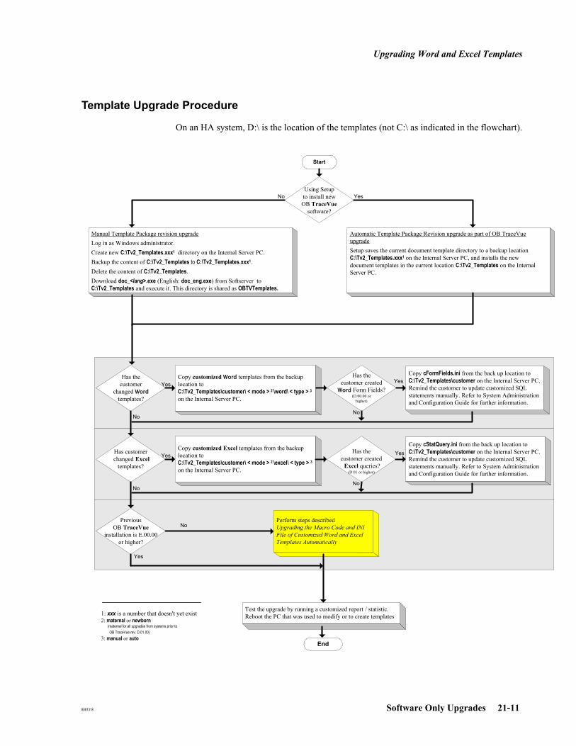
Upgrading Word and Excel Templates
8081318 Software Only Upgrades 21-11
Template Upgrade Procedure
On an HA system, D:\ is the location of the templates (not C:\ as indicated in the flowchart).
Has the customer
changed Word templates?
Start
Copy customized Word templates from the backup location toC:\Tv2_Templates\customer\ < mode > 2 \word\ < type > 3on the Internal Server PC.
Using Setupto install new OB TraceVue
software?
Manual Template Package revision upgradeLog in as Windows administrator.Create new C:\Tv2_Templates.xxx1 directory on the Internal Server PC. Backup the content of C:\Tv2_Templates to C:\Tv2_Templates.xxx1.Delete the content of C:\Tv2_Templates. Download doc_<lang>.exe (English: doc_eng.exe) from Softserver to C:\Tv2_Templates and execute it. This directory is shared as OBTVTemplates.
End
Test the upgrade by running a customized report / statistic. Reboot the PC that was used to modify or to create templates
Has the customer created
Word Form Fields?(D.00.00 or
higher)
Automatic Template Package Revision upgrade as part of OB TraceVue upgrade Setup saves the current document template directory to a backup location C:\Tv2_Templates.xxx1 on the Internal Server PC, and installs the new document templates in the current location C:\Tv2_Templates on the Internal Server PC.
Copy cFormFields.ini from the back up location toC:\Tv2_Templates\customer on the Internal Server PC.Remind the customer to update customized SQL statements manually. Refer to System Administration and Configuration Guide for further information.
Yes
No
YesNo
1: xxx is a number that doesn't yet exist2: maternal or newborn
(maternal for all upgrades from systems prior to OB TraceVue rev. D.01.00)
3: manual or auto
Perform steps described Upgrading the Macro Code and INI File of Customized Word and Excel Templates Automatically
Has customer changed Excel
templates?
Copy customized Excel templates from the backup location toC:\Tv2_Templates\customer\ < mode > 2 \excel\ < type > 3on the Internal Server PC.
Has the customer created Excel queries?
(D.01 or higher)
Copy cStatQuery.ini from the back up location toC:\Tv2_Templates\customer on the Internal Server PC.Remind the customer to update customized SQL statements manually. Refer to System Administration and Configuration Guide for further information.
Yes
No
No
Yes
Yes
PreviousOB TraceVue
installation is E.00.00 or higher?
No
Yes
No

Upgrading Word and Excel Templates
21-12 Software Only Upgrades 8081318
Upgrading the Macro Code and INI File of Customized Word and Excel Templates Automatically
The following single procedure automatically upgrades both Word and Excel templates for software revision D.01.xx.
1. Use the flow chart shown in Template Upgrade Procedure on page 21-11 to determine which upgrade procedure to follow. This procedure is the yellow colored box.
2. Shut down OB TraceVue at the external database PC.3. Log in as Windows administrator.4. Start Update Document Templates on the external server PC. (Start → Programs → OB
TraceVue Support). Verify that no error messages appear. If no errors occur, the automatic upgrade has been successful. If errors occur you must update the templates manually. See Upgrading the Macro Code of Customized Word Templates Manually on page 21-12 and Upgrading Customized Excel Templates Manually on page 21-13, and Upgrading the INI Files of Customized Form Fields and Statistic Queries Manually on page 21-13.
5. Verify that any customization to the template’s paragraph and character styles, formatting and so forth is preserved. Update it if necessary.
Upgrading theMacro Code of
Customized WordTemplates Manually
The following procedure lets you manually upgrade the macro code of customized Word templates. Use it if errors occur during the automatic upgrade procedure.
1. Login as Windows administrator on the external server PC or on any other PC with MS-Office installed. Do not start OB TraceVue.
2. Connect to the Internal Server PC, select the customized file (for example, \\<server>\OBTVTemplates\customer\maternal\word\manual\MyTemplate.dot).
3. Remove the Read-Only attribute, then open the file.4. Select the contents of the template and copy the selection to the clipboard.5. Open a suitable empty factory template under the path
\\<server>\OBTVTemplates\factory\<mode>1\word\*.dot as a template, for example TVReportM.dot. (Within Word use File → Open.) "1" equals either maternal or newborn.
6. Paste the contents of the clipboard to the empty template.Note: the template you wish to copy must be open during paste to preserve page header/footer and other formatting information.
7. Close the original template.8. Overwrite the original template with the newly created template.
(for example \\<server>\OBTVTemplates\customer\maternal\word\manual\MyTemplate.dot)
9. Close the updated file (File → Close).10. Re-apply the Read-Only attribute.
Upgrading Word and Excel Templates
8081318 Software Only Upgrades 21-13
UpgradingCustomized Excel
Templates Manually
The following procedure lets you manually upgrade the customized Excel templates. Use it if errors occur during the automatic upgrade procedure.
1. Login as Windows administrator on the external server PC or on any other PC with MS-Office installed. Do not start OB TraceVue.
2. Connect to the Internal Server PC, create the directory \\<server>\OBTVTemplates\customer\maternal\excel\temp.
3. Copy *.xlt from \\<server\OBTVTemplates\factory\maternal\excel\manual to \\<server\OBTVTemplates\factory\maternal\excel\temp.
4. Re-customize maternal Excel templates in the folder \\<server\OBTVTemplates\customer\maternal\excel\temp.
5. Update the SQL statements of customized queries manually. See the System Administration and Configuration Guide for instructions.
6. Copy the re-customized Excel templates from \\<server\OBTVTemplates\customer\maternal\excel\temp to \\<server\OBTVTemplates\customer\maternal\excel\manual
7. Delete \\<server\OBTVTemplates\customer\maternal\excel\temp.8. Recustomize Newborn Excel templates; follow the steps given above making sure you
use the newborn directory.
Upgrading the INIFiles of Customized
Form Fields andStatistic Queries
Manually
Perform the following procedure if errors occur during the automatic upgrade have occurred.
Perform this step, updating the customized INI files if you are manually upgrading from software revision D.xx to F.xx (it is not necessary for an E to F upgrade) or a customer who has already customized statistic queries or form fields. Otherwise, skip to the next step.
Updating the customized INI files shifts the contents of columns (SQL, Description) to its correct place. Default values in new columns (Mode, Obsolete) may be entered.
1. Open \\<server>\OBTVTemplates\code\SQLedit.xls.
2. Click the tab Report Form Fields (customized).3. Select the whole customized range.4. Select a cell below (outside of) the customized range.5. In the red range:
a. Move Description-cells to the Description column
b. Move SQL-cells to the SQL column
c. Enter the default cell values for Obsolete column: “N” (uppercase)
d. Enter the default cell values for Mode column: “M” (uppercase)
6. Click the tab Statistic Queries (customized) and repeat steps 3 - 5 inclusive.7. Save the workbook.

Upgrading Word and Excel Templates
21-14 Software Only Upgrades 8081318
Introduction
8081318 Hardware and Software Upgrades 22-1
22Hardware and Software Upgrades
IntroductionThis chapter describes how to upgrade the OB TraceVue PC hardware and software to the latest version.
Prerequisites (All Upgrades)
Make sure that the PCs you are usingare supported by OB TraceVue (see Supported PCs on page 20-2)meet the memory requirements (see Memory Requirements on page 20-3)
Make sure that the network topology and cabling meets the requirements of this OB TraceVue revision. See Network Specifications on page 6-8 and Cable Specifications on page 6-9.
Consider network security issues. See Task 38: Network Security on page 5-33.Remove the second network interface (if installed) from the internal server PC (except when upgrading to a high availability server pair), and from the external server and client PC.
Upgrading or Exchanging the Hardware with Software at Revision D.00.00 or Higher
22-2 Hardware and Software Upgrades 8081318
Upgrading or Exchanging the Hardware with Software at Revision D.00.00 or Higher
Use this process when upgrading to a different PC or when exchanging the current PC for support purposes.
Upgrading the hardware also requires upgrading the software to the latest version. The software upgrade is also described in this chapter.
Restrictions
You cannot merge two databases during this upgrade.
Preparing all PCs
Check the revisions of the PC BIOS and RAID BIOS (if available), and update them if required.
Check the BIOS settings (in PC sections) and adjust them if required.
Preparing OB TraceVue
Check the BIOS settings (given in the PC-specific chapters of this book) and adjust them if necessary.
Shutdown OB TraceVue and run the Local Data Recovery Tool to ensure that the database has no corruption.
Start OB TraceVue at the internal server and backup the internal database (see the Instructions for Use for details).
Start OB TraceVue at the external server (if available) and backup the external database (see the External Database Guide for details).
Shutdown OB TraceVue and backup OB TraceVue at the internal server and at the external server using the Backup Tool.
Backup the Word and Excel templates (if available) using the Backup Tool.
Print out the installation records of the clients and the WEB/Terminal server if they are to be upgraded.
Upgrading the Internal Server Hardware
UpgradeRequirements
Αn existing internal server with:
Windows 2000 or Windows 2003OB TraceVue D.00.00 or higher
A new internal server with:

Upgrading or Exchanging the Hardware with Software at Revision D.00.00 or Higher
8081318 Hardware and Software Upgrades 22-3
Windows 2003 installed, according to the OB TraceVue installation process for the current OB TraceVue revision.
Prepare Old InternalServer
1. Make sure you have backed up the internal database as described in Preparing OB TraceVue on page 22-2.
2. Make sure you have backed up the internal server using the Backup Tool. Copy all offline backup files to a safe location outside the server (for example, to a client PC, a dedicated MO media, or the FSE’s laptop).
Install New InternalServer
1. Connect the PC to the network.
2. Start Windows.
3. Rename the new PC to the original name of the old internal server.
4. Reboot the PC.
5. Configure the TCP/IP and DHCP Server Configuration on page 19-17 according to the installation process for this revision.
6. Reboot the PC.
7. Copy the offline backup files to the new server.
8. Run OB TraceVue setup from the local CD ROM using the following selections:
Restore a previously saved OB TraceVue installation (from Backup tool).Specify the backup path from which to restore OB TraceVue.Install the OB TraceVue software.Keep network server selection as it currently is.Keep the existing database and datafiles.Do NOT delete the existing database and files.
Caution: If you delete the existing database, all patient data and configuration is lost.
Do not change system settings (no password required).If you want to change the system language, choose “Define System Language”.
Click Finish to reboot the PC, or reboot manually..
9. Restore the backup of the Word/Excel templates file (if available) from x:\Temp.
10. Start the Backup Tool and restore TV2_Templates directory. Confirm overwrite of the template directory.
11. Start the Database Rebuild Tool.
12. Make a backup of the internal database (Configuration Toolbar on the internal server).
13. Apply available OB TraceVue service packs for this software revision.
14. Make sure you set the external database automatic purge time. See Automatic Purge on page 10-4.

Upgrading or Exchanging the Hardware with Software at Revision D.00.00 or Higher
22-4 Hardware and Software Upgrades 8081318
15. If this is an internal server of a linked system, specify the server names and IP addresses of the other internal servers of the link in the System Manager’s Configuration screen, OB TraceVue Link page.
16. Print and backup the configuration record (see Task 40: Print and Back-Up Configuration Record on page 5-34).
17. Print the installation record (see Task 41: Print out PC Installation Record on page 5-34).
18. Re-label the upgraded PC.
Complete the system serial number label (supplied with the upgrade shipment) with the product number and serial number of the replacement PC. Stick the label onto the right side of the new PC; see the existing PC for the exact location.
19. To install new templates, if required, see Installing Word and Excel Templates on page 6-46.
Cleanup Old Server If you have upgraded using new PC hardware, you must make sure you delete the contents of the old PC’s hard disk when you have finished upgrading. This is required as you no longer have software licenses for the old PC.
Use the installation boot floppies to format drive C and D.
Upgrading or Exchanging the Hardware with Software at Revision D.00.00 or Higher
8081318 Hardware and Software Upgrades 22-5
Upgrading the External Database Server Hardware
UpgradeRequirements
Αn existing external database server with:
Windows 2000 or windows 2003OB TraceVue D.00.00 or higher
A new external database server with:
Windows 2003 installed, according to the OB TraceVue installation process for the current OB TraceVue revision.
Prepare OldExternal Server
1. Make sure you have backed up the external database as described in Preparing OB TraceVue on page 22-2.
2. Make sure you have backed up the external server using the Backup Tool. Copy all offline backup files to a safe location outside the server (for example, to a client PC, a dedicated MO media, or the FSE’s laptop).
Install New ExternalServer
1. Connect the PC to the network.
2. Start Windows.
3. Rename the new PC to original name of the old external server.
4. Reboot the PC.
5. Configure the TCP/IP and DHCP Server Configuration on page 19-17 according to the installation process for this revision.
6. Reboot the PC
7. Copy the offline backup files to the new server.
8. Run OB TraceVue setup from the local CD ROM using the following selections:
Restore a previously saved OB TraceVue installation (from Backup tool).Specify the backup path from which to restore OB TraceVue.Install the OB TraceVue software.Keep network client PC selection as it currently is.Do not change system settings (no password required).If prompted: Keep existing external database.
Click Finish to reboot the PC, or reboot manually.
9. Start the Database Rebuild Tool.
10. Perform a manual installation of Microsoft Office. See Installing and Configuring Microsoft Office 2007 on page 6-42.
11. Apply any available OB TraceVue service packs for this software revision.
12. To update customized templates, follow the procedure given in Upgrading Customized Templates on page 21-10.
13. Start OB TraceVue, backup the external database.

Upgrading or Exchanging the Hardware with Software at Revision D.00.00 or Higher
22-6 Hardware and Software Upgrades 8081318
14. Make a backup of the internal database (Configuration Toolbar on the internal server).
15. Print and backup the configuration record (see Task 39: Print and Back-Up Configuration Record on page 5-34).
16. Print the installation record (see Task 40: Print out PC Installation Record on page 5-34).
17. Relabel the upgraded PC:Complete the system serial number label (supplied with the upgrade shipment) with the product number and serial number of the replacement PC. Stick the label onto the right side of the new PC; see the existing PC for the exact location.
Cleanup Old Server If you have upgraded using new PC hardware, you must make sure you delete the contents of the old PCs hard disk when you have finished upgrading. This is required as you no longer have software licenses for the old PC.
Use the installation boot CDs to format drive C and D.
Upgrading or Exchanging the Hardware with Software at Revision D.00.00 or Higher
8081318 Hardware and Software Upgrades 22-7
Upgrading the WEB/Terminal Services Server PC Hardware
1. Make sure that OB TraceVue is up and running on the internal server.
2. Connect the new PC hardware to the network and boot it up.
3. Install OB TraceVue as described in OB TraceVue Installation on page 18-1 and enter the settings from the previously printed installation record.
Note You must install OB TraceVue software using add/remove programs. Do not use the Explorer to start setup.exe.
4. Apply available OB TraceVue service packs for this software revision.
Cleanup Old PC If you have upgraded using new PC hardware, you must make sure you delete the contents of the old PCs hard disk when you have finished upgrading. This is required as you no longer have software licenses for the old PC.
Use the installation boot floppies to format drive C and D.
Upgrading Client PC Hardware
1. Make sure that OB TraceVue is up and running on the internal server.
2. Connect the new PC hardware to the network and boot it up.
3. Install OB TraceVue as described in OB TraceVue Installation on page 18-1 and enter the settings from the previously printed installation record.
4. Apply available OB TraceVue service packs for this software revision.
Cleanup Old PC If you have upgraded using new PC hardware, you must make sure you delete the contents of the old PCs hard disk when you have finished upgrading. This is required as you no longer have software licenses for the old PC.
Use the installation boot floppies to format drive C and D.
Upgrading Real-Time WEB Client
To upgrade real-time WEB clients, see Real-Time WEB Client on page 5-40.
Final Steps After Upgrade is Complete
If Moxa 5610 Serial Port servers are part of the system, check the firmware and upgrade if necessary. See Installing and Setting up a Serial Port Server on page 6-13.
After the system upgrade is complete, and the OB TraceVue system is restarted, run the Update Archive Tool on one OB TraceVue PC.

Upgrading or Exchanging the Hardware with Software at Revision D.00.00 or Higher
22-8 Hardware and Software Upgrades 8081318

Introduction
8081318 System Upgrades 23-1
23System Upgrades
IntroductionThis chapter describes how to upgrade an entire OB TraceVue system:
Upgrading to Storage System (Standalone Drives)
Upgrading To Storage System (Medium Changers)
Upgrading From Standard/High-end Internal Server to High Availability Server Pair
Adding a Retrieve Drive
Adding an Optical Medium Changer (Jukebox)
From Standalone to Network Server
From Small Network to Larger Network
Adding Web Client Licenses
Adding WEB/Terminal Server PC
Adding External Database Server PC
Merging or Linking Systems
Remember, when you add (or delete) PCs you must make a new configuration backup record (see Print and Back-Up Configuration Record on page 5-34) and installation record printout (see Print out PC Installation Record on page 5-34).
Upgrading to Storage System (Standalone Drives)
23-2 System Upgrades 8081318
Upgrading to Storage System (Standalone Drives)
1. If required, install SCSI host adapter. See SCSI Host Adapter on page 13-6.
2. Install secondary hard disk (not on RAID systems). See Secondary Hard Disk Drive (for Storage Systems) on page 13-7.
3. Connect the optical drive(s). See Optical Drives on page 13-9 4. Start OB TraceVue setup.
Select Change database settings or System Options. See System Settings on page 18-5.Select Storage.Select Define Server Drives settings. See Server Name (client only) on page 18-9.
Upgrading To Storage System (Medium Changers)
1. If required, install SCSI host adapter. See SCSI Host Adapter on page 13-6.
2. Install secondary hard disk (not on RAID systems). See Secondary Hard Disk Drive (for Storage Systems) on page 13-7.
3. Connect the changer. See Optical Medium Changers (Autochanger/Jukebox) on page 13-11.
4. Power-up the medium changer and boot the server PC.
5. Install the Windows device driver. See Optical Medium Changers (Jukeboxes) on page 19-31.
6. Start OB TraceVue setup.
Select Only change database settings or System Options. See System Settings on page 18-5.Activate Storage.In the Assign disk drives dialog, select the backup drive and check Use the installed Autochanger. See Archive Drive Settings on page 18-8.
7. Start OB TraceVue.
8. Feed the optical media into disk changer via the optical disk dialog of OB TraceVue.
See Troubleshooting the Removable Storage Manager on page 9-8 if OB TraceVue is unable to initialize the removable storage manager.

Adding a Retrieve Drive
8081318 System Upgrades 23-3
Adding a Retrieve Drive
1. Shut down OB TraceVue, and switch off the PC.
2. Connect the second optical drive. See Optical Drives, HP Optical Drive Settings on page 13-9.
3. Power on the optical drive.
4. Switch on the PC.
5. Start OB TraceVue setup.
Select Change database settings or System Options. See System Settings on page 18-5.Select Define Server Drives settings. See Server Name (client only) on page 18-9.
Adding an Optical Medium Changer (Jukebox)
Note OB TraceVue supports one optical medium changer plus one standalone optical drive.
1. Connect the changer. See Optical Medium Changers (Autochanger/Jukebox) on page 13-11.
2. Power-up the medium changer and boot the server PC.
3. Install the device driver. See Optical Medium Changers (Jukeboxes) on page 19-31.
4. Stop 'Removable Storage' Service (RSM) ( All programs →Administrative Tools → Services)
5. Delete all files in the directory c:\win2003\system32\NtmsData.
6. Restart the RSM service. The RSM detects that all devices are correct.
7. Start OB TraceVue setup.
Select Only change database settings or System Options. See System Settings on page 18-5.Activate Storage.In the Assign disk drives dialog, select the backup drive and in the Archive settings dialog, check Use installed Autochanger. See Archive Drive Settings on page 18-8.
8. Feed optical media into disk changer.
9. Start OB TraceVue.
See Troubleshooting the Removable Storage Manager on page 9-8 if OB TraceVue is unable to initialize the removable storage manager.
From Standalone to Network Server
23-4 System Upgrades 8081318
From Standalone to Network Server
1. Connect the standalone to the network.2. If required, change the name of the PC in the operating system (Control Panel).3. In the operating system, install the DHCP server service. See also Manual Windows
Configuration on page 19-17.4. Share the CD-ROM drive as CDROM.5. Check the PC’s BIOS and update it if required.
6. Run OB TraceVue server setup. 7. Update Windows licenses and OB TraceVue licenses as described in Updating OB
TraceVue Licenses on page 23-4.
8. Run OB TraceVue setup on all client PCs.9. Connect and install the printer to a client and then share it.
From Small Network to Larger NetworkIf a customer increases the size of the network you must add and set up clients following the Windows and OB TraceVue installation instructions.
Updating OB TraceVue Licenses1. Run the OB TraceVue setup on the server PC.2. Select Only change database settings or system settings.
3. Select Change System Settings.4. Increase the number of clients.5. Finish Setup to reboot the server PC.
Adding Web Client Licenses
8081318 System Upgrades 23-5
Adding Web Client LicensesIf a customer wants to add additional OB TraceVue Web Client licenses, these can be ordered separately.
For the maximum number of Web Client licenses supported on a single WEB/Terminal Server PC see WEB/Terminal Server on page 20-7.
If more licenses are required additional WEB/Terminal Server PCs have to be installed. Additionally the total number of client PC’s (Web clients and network clients) must not exceed the limits for the currently used internal server hardware.
The number of client licenses must be increased at the following places:
1. Updating Terminal Services Configuration on WEB/Terminal Server PC
a. Start the Terminal Services Configuration tool: Start → Programs → Administrative Tools → Terminal Services Configuration.
b. In the left pane select Connections, in the right pane select OBTV Tcp.
c. From the menu select Action → Properties.
d. Choose the Network Adapter tab.
e. Increase the maximum number of connections entry box by the number of additional licenses. Refer to WEB/Terminal Server on page 20-7 for the maximum number that can be entered here.
2. Updating License Information at Internal Server PC
Follow the instructions in From Small Network to Larger Network on page 23-4 to increase the licenses at the internal server PC. Web Client licenses are handled and counted at the internal server as normal OB TraceVue client licenses.
Adding WEB/Terminal Server PCFor adding WEB/Terminal Server PC follow the Windows and OB TraceVue installation instructions for that PC type. Refer to the according chapters in “New System Installation”.
Additionally the licenses at the internal server PC have to be updated. Follow the instructions in From Small Network to Larger Network on page 23-4 to increase the number of licenses according to the Web Client licenses that come pre installed with the WEB/Terminal Server PC.
Check the PC BIOS and RAID BIOS (if available), and update them if required.
Adding External Database Server PC
23-6 System Upgrades 8081318
Adding External Database Server PCAfter the installation of an External Database Server PC on an existing system you have to restart OB TraceVue on the internal server.
Merging or Linking Systems
Introduction
The following diagram gives an overview of the process for merging or linking systems.
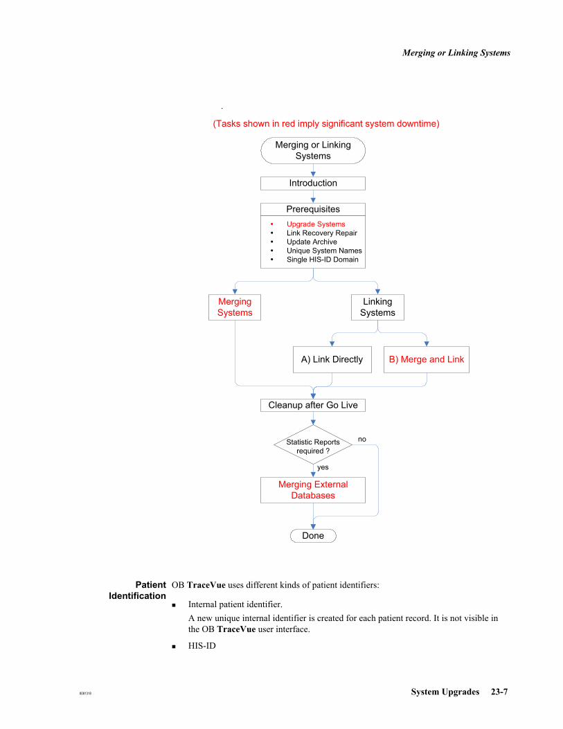
Merging or Linking Systems
8081318 System Upgrades 23-7
PatientIdentification
OB TraceVue uses different kinds of patient identifiers:
Internal patient identifier.A new unique internal identifier is created for each patient record. It is not visible in the OB TraceVue user interface.
HIS-ID
Merging or LinkingSystems
Introduction
PrerequisitesUpgrade SystemsLink Recovery RepairUpdate ArchiveUnique System NamesSingle HIS-ID Domain
MergingSystems
LinkingSystems
B) Merge and LinkA) Link Directly
Cleanup after Go Live
Merging ExternalDatabases
Statistic Reportsrequired ?
Done
yes
no
(Tasks shown in red imply significant system downtime)
p

Merging or Linking Systems
23-8 System Upgrades 8081318
Medical Record Number, Social Security Number or Patient Identification are referred to as HIS ID. HIS-IDs are used by HL7/HIS systems to identify patients. Only one can be designated as the HIS ID for the ADT interface.
Patient DemographicsWhen searching for a patient record in the Identify/Search Patient screen, demographic data can also be used to identify a patient.
MultipleAdmissions
A patient should have exactly one HIS-ID and should be admitted to OB TraceVue exactly once.
However, it is possible to create multiple patient records for the same physical patienton a single system (if the HIS-ID is misspelled)on linked systems, even if an identical HIS-ID is entered.on separate systems.
Note A single OB TraceVue patient record can be distributed over multiple OB TraceVue systems by transferring the record via OB TraceVue Link. It may have different documentations and episodes on different systems, but is still a single record. The so called Link token ensures that the record can only be continued on one system. A new episode can only be created on that system, that currently owns the token.
Merging/LinkingSystems
When linking or merging previously unrelated systems, multiple patient records with identical HIS-ID are handled as follows:
the records are considered to belong to the same physical patientthe record with the latest episode is enabledall other records are disabled
This is required to guarantee uniqueness of HIS-IDs within one single system.
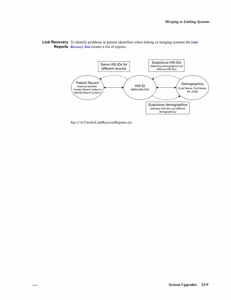
Merging or Linking Systems
8081318 System Upgrades 23-9
Link RecoveryReports
To identify problems in patient identifiers when linking or merging systems the Link Recovery Tool creates a list of reports:
See c:\tv2\tools\LinkRecoverReports.xls
Patient Record(Internal identifier.
“Create Patient” button in Identify/Search screen)
HIS-ID(MRN,SSN,PID)
Demographics(Last Name, First Name,
MI, DOB)
Same HIS-IDs for different records
Suspicious HIS-IDs(Matching demographics but
different HIS-IDs)
Suspicious demographics(Identical HIS-IDs, but different
demographics)

Merging or Linking Systems
23-10 System Upgrades 8081318
Prerequisites (for Merging and for Linking)
Upgrade Systems Upgrade each system to the latest software version separately. Do not create new OB TraceVue links.
See Chapter 20, Upgrade Overview.
Note It is sufficient to upgrade the internal server and archiving server. Client PCs can be upgraded and used in parallel independent of the merge/link process.
Run Link Recovery Run the Link Recovery Tool separately on each cluster of linked systems.

Merging or Linking Systems
8081318 System Upgrades 23-11
See Link Recovery Tool for full details of the PCs on which the tool should be run.
When you run the Link Recovery Tool:
Do not select Reporting Only Do not skip Repair.
System 2
Cluster A
Cluster B
System 5
S5
L
System 4
S4
L
SRV2
Cli
Cli
CliLinkPC
Cli
System 1
SRV1
Cli
Cli
Cli
LinkPC
Cli
Example of a new OB TraceVue LinkSystem 4 and System 5 are linked toSystem 1 and 2 to combinecluster A and B to a single cluster
Archive
System 3
S3
L
Archive
Example of a mergeSystem 3 is discontinuedIts data is merged into System 1

Merging or Linking Systems
23-12 System Upgrades 8081318
Update Archive On all systems:
Start OB TraceVue at the internal server PC, the external server PC, and at the HL7 client PC.Run c:\tv2\prog\UpdateArchive.exe.
This automatically creates, and closes, episodes which OB TraceVue requires for internal administration purposes. It could be rather time consuming. The system can be used while this is taking place. Performance of some portions of OB TraceVue may decrease, such as retrieving, and reports printing.
Update Archive tool can be stopped safely as soon as it enters the "Waiting for X closed episodes...." status. In the background, the system automatically archives the closed episodes.
Link and Merge can be done later during a separate downtime of the affected system(s). This allows an uptime period where necessary manual patient identification cleanup tasks can be made (e.g. systematic changes of HIS-IDs, correcting misspelled HIS-IDs, …)
Unique SystemNames
Configure unique system names for all affected systems in the System Managers Configuration, page OB TraceVue Link.
Note the previous system names and store in a safe place. They might be requested by the Retrieve from Archive (RFA Wizard) in the future.
The system name is used in the Link Recovery Tool to configure and identify the systems. It is also shown in the reports to indicate which system currently has the responsibility for a patient record.

Merging or Linking Systems
8081318 System Upgrades 23-13
Single HIS-IDDomain
HIS-IDs (MRN, SSN or PID) are usually created by a HIS System. The "pool" of the HIS-IDs is called HIS-ID domain. HIS-IDs created within one HIS-ID domain are unique. Other HIS-ID domains (e.g. of a different hospital) may use the same HIS-ID for a different patient.
When merging or linking previously unrelated systems it is required that the systems have a single HIS-ID domain.
A HIS-ID must be unique and refer to exactly one physical patient.
If this is not the case because either of the unrelated systems was using a different HIS-ID domain containing HIS ID's overlapping with the other system, the HIS-IDs on one of the systems must be changed:
Manually using the Patient Administration dialog for closed episodes Manually using the demographics form for open episodes Automated using HL7 A47 messages.
Before using A47, Run the Link Recovery Tool and create the report Records without HIS ownership. This report lists all records, that would not be affected by a A47 message. Verify that the record has the correct HIS-ID and establish the HIS ownership. HIS ownership can be established using the Patient Administration dialog (only for closed episodes).
Note There is no need to handle multiple admissions of the same physical patient with identical HIS-ID at this point in time. This will be handled automatically by OB TraceVue.
Note. Sending an A01 message with IDENTICAL patient demographics will reassign HIS ownership for open and closed episodes.

Merging or Linking Systems
23-14 System Upgrades 8081318
Merging Systems
Ensure that a new (empty) optical disk is available. It is required immediately after the merge.
Preparing AllSystems for
Merging
1. Run the Link Recovery Tool on a PC that has connections to all internal server PCs of all OB TraceVue link clusters that will participate in the merge. Include all internal server PCs of all the OB TraceVue link clusters that will participate in the merge.
For previously unlinked systems, select Reporting Only.
For previously linked systems, do not select Reporting Only.
2. Create the report Same HIS-IDs for different records.
Let a clinical person review the results and correct wrong HIS-IDs in all cases where the same HIS-ID refers to physically different patients (e.g. misspelled HIS-IDs). To easily change HIS-IDs for closed episodes, use the OB TraceVue Patient Administration Dialog.
For open episodes, this must be done at the demographic forms page.
Note There is no need to handle multiple admissions of the same physical patient at this time. During import, RFA resolves conflicts of all HIS-IDs.If the same MRN or SSN or Patient Identification is found for another record, the record that has the newest episode will remain unmodified. The other record gets disabled1 and is later shown with a red cross in the Identify/Search screen.
Preparing theDiscontinued
System
1. On the source system (ie the system that will be merged and then discontinued):
a. Close all open episodes.
Use Identify/Search screen filter Open Episodes to find all of them.
b. Execute c:\tv2\prog\UpdateArchive.exe.
Wait until the tool displays:
Waiting for 0 closed episode(s) to be archived, (0 open), press ’Stop’ to cancel wait.
Update Archive successfully finished.
Press Close to exit the tool.
In rare cases, the numbers might not decrease to 0. This could be due to past recovery situations. In such cases, keep the offline backup in a safe place and contact your local Philips support engineer. As the tool will not automatically terminate, you must terminate it manually when there is no further activity on the optical disk.
1. Disabled record means that the record cannot have new episodes, but all data is available.
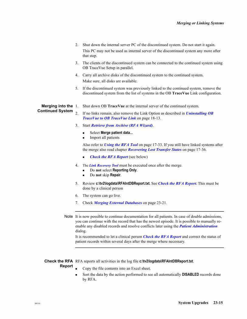
Merging or Linking Systems
8081318 System Upgrades 23-15
2. Shut down the internal server PC of the discontinued system. Do not start it again.This PC may not be used as internal server of the discontinued system any more after that step.
3. The clients of the discontinued system can be connected to the continued system using OB TraceVue Setup in parallel.
4. Carry all archive disks of the discontinued system to the continued system.Make sure, all disks are available.
5. If the discontinued system was previously linked to the continued system, remove the discontinued system from the list of systems in the OB TraceVue Link configuration.
Merging into theContinued System
1. Shut down OB TraceVue at the internal server of the continued system.
2. If no links remain, also remove the Link Option as described in Uninstalling OB TraceVue to OB TraceVue Link on page 18-13.
3. Start Retrieve from Archive (RFA Wizard).
Select Merge patient data... Import all patients
Also refer to Using the RFA Tool on page 17-33. If you still have linked systems after the merge also read chapter Recovering Lost Transfer States on page 17-36.
Check the RFA Report (see below)
4. The Link Recovery Tool must be executed once after the merge.Do not select Reporting Only. Do not skip Repair.
5. Review c:\tv2\logdata\RFAIntDBReport.txt. See Check the RFA Report. This must be done by a clinical person
6. The system can go live.
7. Check Merging External Databases on page 23-21.
Note It is now possible to continue documentation for all patients. In case of double admissions, you can continue with the record that has the newest episode. It is possible to manually re-enable any disabled records and resolve conflicts later using the Patient Administration dialog. It is recommended to let a clinical person Check the RFA Report and correct the status of patient records within several days after the merge where necessary.
Check the RFAReport
RFA reports all activities in the log file c:\tv2\logdata\RFAIntDBReport.txt.
Copy the file contents into an Excel sheet.Sort the data by the action performed to see all automatically DISABLED records done by RFA.

Merging or Linking Systems
23-16 System Upgrades 8081318
Check if the correct record has been disabled; if not use the Patient Administration dialog to correct it.It is recommended to save the excel file for documentation.

Merging or Linking Systems
8081318 System Upgrades 23-17
Linking Systems
A network connection between systems to be linked is a prerequisite.
Link Methods There are two ways to establish a link between previously unlinked systems. Deciding which is easier to implement during upgrade depends on the use model of the previously unlinked systems. To decide, execute the following:
1. Run the Link Recovery Tool on a PC that has connections to all affected internal servers.
Select Reporting Only.Configure all internal servers to be linked.Create the report Same HIS-IDs for different records.
2. Correct the HIS-ID in all cases where the same HIS-ID refers to physically different patients. Use the Patient Administration dialog to change HIS-IDs for closed episodes. Use the Demographics form for open episodes.Ignore multiple admissions.
3. Run the Link Recovery Tool again.Create the report Same HIS-IDs for different records.It should only show multiple admissions of same physical patients now.
Is it possible to clean up the multiple admissions manually?Yes, cleanups can be done manuallyThis is the quickest way to establish the new OB TraceVue link.Continue with A) Link Directly
No, there are too many multiple admissionsCleaning up the multiple admissions manually will take longer than the system merge.Continue with B) Merge and Link
A) Link Directly
1. Configure the OB TraceVue link between the systems.
2. Run the Link Recovery Tool.Do not select Reporting Only. Do not skip Repair.Configure all internal servers.Create all reports
3. Cleanup the patient records listed in report Same HIS-IDs for different records.For each group of identical HIS-IDs the topmost record is the one with the newest episode. Determine the record, that should be continued and disable all other records using the Patient Administration dialog on the system that is indicated in the first column (e.g. via OB TraceVue TS client).
4. The system can go live, once you cleaned up all current patient records.To avoid potential admission conflicts in the future, you should execute the Cleanup

Merging or Linking Systems
23-18 System Upgrades 8081318
after Go-Live within several days after the new link.
B) Merge and Link
This alternative merges one of the systems to the other according to previous chapter.
The linked system is re-installed with an empty internal database. All old patient records reside in one system after the link. Please note, that with Revision E you can easily pull records from one system to the other for continuation. Therefore, it is not important any more on which of the systems the record currently resides.
1. Execute the merge process described in Merging Systems on page 23-14.
2. Install the second system with a new (empty) database and configure OB TraceVue Link.
3. The system can go live immediately after the merge process.
Upgrading from Optical Disks to Network Based Storage
When upgrading to network based storage, use the optical disk migration tool to copy the content of all needed optical disks to the network storage location. Do not remove optical disk hardware from archive PC until all optical disks are migrated.
Upgrade to NetworkStorage Location:
1. Create a backup using Backup Tool
2. Use OB TraceVue setup to configure the network storage location.
3. Startup OB TraceVue (this is to create an Archive Index on Storage location)
4. Start optical disk migration tool.
a. Select the optical disk to copy.
b. Select the destination location.
c. Run copy process.
d. Select a new disk to copy if necessary.
All disk data that are copied to the network storage location are now available for retrieve or running the RFA tool.
Optical DiskMigration Tool
The Optical Disk Migration tool is a wizard-based tool that allows you to copy the data stored on OB TraceVue optical disks to the network storage location. The tool supports standalone optical drives, and optical auto-changers where it is possible to select more than one disk.
You use the wizard to select the disk for copying and the destination directory. The tool copies the data to the destination. If a directory already exists for the selected optical disk at the destination, the copy process is rejected. If an error occurs during copy or the you interrupt the file copy process, the whole destination directory will be removed.
The Optical Disk Migration tool allows you to specify a destination path and it allows you to

Merging or Linking Systems
8081318 System Upgrades 23-19
enter user credentials that are used to access this location.
The Optical Disk Migration tool and the process of disk migration to a network storage location can run in parallel with OB TraceVue.
You are recommended to copy as many disks as possible during an upgrade in order to minimize the chance that old records required for retrieval are unavailable, remaining on as yet uncopied disks.

Merging or Linking Systems
23-20 System Upgrades 8081318
Cleanup after Go-Live
To go-live it is only necessary to cleanup current patient records. To avoid conflicts in the future it is recommended to cleanup all patient records within a short period of time after the link.
Recommendations Use one single MRN for all previous records of a physical patient.The older records are disabled to protect them from unintended continuation. It is possible to retrieve, review and print episodes of disabled records.Change records with HIS-IDs such as DO NOT USE xxx to a disabled record with the correct HIS-ID and demographic data.
Use consistent demographics for all records of a physical patient.This helps when searching for old records of the patient.
To create reports run the Link Recovery Tool on a PC that has connections to all affected internal servers. Configure all affected internal servers.
Generate all reports, especially the report Suspicious demographics or HIS-IDs.
The reports cannot detect multiple records that differ in both HIS-ID and demographics. They are treated as separate patients.
Use Identify/Search screen search capabilities of OB TraceVue Administration Tool and the report AllRecords.txt generated by the Link Recovery Tool to identify these records.
The goal is, that all reports finally are empty (except AllRecords of course).
The report Same HIS-IDs for different records is strongly recommended to be empty to avoid unexpected conflicts in the running OB TraceVue system e.g. at night or if the person trying to admit a patient does not have the skills to resolve the conflict.
The customer might want to have a remaining reviewed list of records (e.g. of test patients) in the report “Patient records that are disabled on all systems”.

Merging or Linking Systems
8081318 System Upgrades 23-21
Merging External Databases
Notes Retrieved episodes can be printed normally without merging the external databases.A merge of external databases solely makes sense for statistical reports.Records of the same patient that were created independently on different systems are interpreted as two patients by statistics. For example, if a pregnancy was documented in parallel in two records, it counts twice. However, a pregnancy started on one system, sent over to the other system and completed there, counts once.
If many patients were documented in parallel on the previously unrelated systems, re-starting with a new external database instead of a merged database could produce better results.
It is also possible to continue with the external database of the first system without restoring the external database of the merged system.
To merge external databases, refer to Restoring the External Database on page 17-37.
Merging external databases can be very time consuming. It can be postponed to a later downtime of the system. The statistics will analyze all data of the other system that was restored by RFA “Restore External Database”.

Merging or Linking Systems
23-22 System Upgrades 8081318

8081318 Compaq Evo D510 PC 24-1
24Compaq Evo D510 PC
Specifications
This chapter refers to the Compaq Evo D510 CMT PC (M3167-60003):
All Configurations:
All Compaq Evo D510 PCs supplied for OB TraceVue include:
A sound card onboard.
A 10/100 BaseT LAN adapter onboard.
Two RS-232 serial ports (COM ports).
Optional Configurations:
Compaq Evo D510 PCs supplied for OB TraceVue may be fitted with:
A PCI RS-232 Serial Interface that provides two additional COM ports, COM3 and COM4.
A Lightpen card. The lightpen option adds the lightpen, lightpen holder, and lightpen extension lead.
A second network interface card (only if PC is used as a WEB/Terminal Services PC or a non-data acquisition client).
Server only: A PCI SCSI adapter card. The patient data storage option adds an internal 2nd IDE hard disk, and either one, or two external optical disk drive(s).
Removing the PC Cover
Before working inside the PC, refer to the detailed instructions for removing and replacing the PC's cover and other items (such as the PC's power supply) given in the:
Compaq Evo D510 PC Hardware Reference Guide on the Documentation Library CD.

Specifications
24-2 Compaq Evo D510 PC 8081318
Slot Assignments for Compaq Evo D510
Note Slot numbers marked on the backpanel or on the system board of the PC may differ from the slot numbering used in this chapter: Slot numbering in this chapter: Slot 1 is closest to the left of the computer (rear view).
* It is not possible to have all due to mechanical conflicts.
Lightpen Settings for Compaq Evo D510
For detailed information about the lightpen, refer to FTG Data Systems’ PXL-595 (PCI) User’s Guide.
The IRQ is auto-assigned. No manual configuration is necessary.
Soundcard Settings for Compaq Evo D510
The IRQ is auto-assigned. No manual configuration is necessary.
RS-232 I/F Card for Compaq Evo D510
Two RS-232 COM Ports, Serial A and Serial B are built into the PC. A PCI RS-232 serial interface may be fitted to provide a total of four COM ports.
Table 24-1 Slots for Compaq Evo D510 PCs
Accessory Card and Type Slot Number
Network Interface Onboard
Display adapter Onboard
RS-232 Serial I/F Onboard
Add. RS-232 Serial I/F 2
SCSI Interface (internal Server) 3
2nd Network Interface (Web/TerminalServer or non-dataacquisition client)
3
Lightpen (PCI) 4*
Sound Card Onboard

Configuration and Setup Tables
8081318 Compaq Evo D510 PC 24-3
Configuration and Setup Tables
This section provides configuration and setup tables for Compaq Evo D510 PCs.
BIOS Version for Compaq Evo D510
The required BIOS version is v2.21.
If you need to update the BIOS: On the OB TraceVue application software installation CD-ROM, start Firmware\D510_Bios.bat
BIOS Settings for Compaq Evo D510
To view or change a PC's BIOS settings:
1. Power down the PC using its on/off switch.2. Turn on the PC.3. During the Compaq welcome screen, press F10 (Setup). Select the language and press
Enter.4. Follow the on-screen instructions to view and change different screens and settings.
To load the OB TraceVue default BIOS settings:
1. Follow steps 1 through 4 described above (To view or change a PC’s BIOS settings).
2. Select Set Defaults and Exit. Press Enter and follow the instructions.
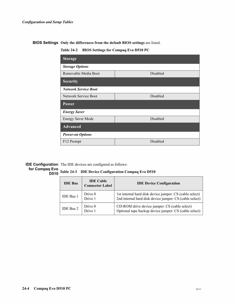
Configuration and Setup Tables
24-4 Compaq Evo D510 PC 8081318
BIOS Settings Only the differences from the default BIOS settings are listed.
IDE Configurationfor Compaq Evo
D510
The IDE devices are configured as follows:
Table 24-2 BIOS Settings for Compaq Evo D510 PC
Storage
Storage Options
Removable Media Boot Disabled
Security
Network Service Boot
Network Service Boot Disabled
Power
Energy Saver
Energy Saver Mode Disabled
Advanced
Power-on Options
F12 Prompt Disabled
Table 24-3 IDE Device Configuration Compaq Evo D510
IDE Bus IDE Cable Connector Label IDE Device Configuration
IDE Bus 1 Drive 0Drive 1
1st internal hard disk device jumper: CS (cable select)2nd internal hard disk device jumper: CS (cable select)
IDE Bus 2 Drive 0Drive 1
CD-ROM drive device jumper: CS (cable select)Optional tape backup device jumper: CS (cable select)

Configuration and Setup Tables
8081318 Compaq Evo D510 PC 24-5
SCSI BIOS Settings for Compaq Evo D510
This section applies to server and standalone PCs fitted with the storage option. The SCSI BIOS is separate from the PC BIOS.
OB TraceVue requires the default SCSI BIOS settings. To ensure that these defaults are loaded:
1. Reboot the PC. Early in the Compaq welcome screen press ESC to get to the startup screen. Watch the screen carefully.
2. When the Symbios screen prompts you, early in the startup procedure, press F6.
3. In the main menu make sure SYM53C895 is selected, then press Enter.
4. Select Adapter Setup, then press Enter.
5. Select Restore Default Setup, then press Enter.
6. Save Changes.
Interrupt Adjustments for Compaq Evo D510
All IRQs are auto-assigned. No manual configuration is necessary.

Configuration and Setup Tables
24-6 Compaq Evo D510 PC 8081318

8081318 HP Compaq D530 PC 25-1
25HP Compaq D530 PC
Specifications
This chapter refers to the HP Compaq D530 CMT PC (M3167D):
All Configurations:
All HP Compaq D530 PCs supplied for OB TraceVue include:
A sound card onboard.
A 10/100 BaseT LAN adapter onboard.
Two RS-232 serial ports (COM ports).
Optional Configurations:
HP Compaq D530 PCs supplied for OB TraceVue may be fitted with:
A PCI RS-232 Serial Interface that provides two additional COM ports, COM3 and COM4.
A Lightpen card. The lightpen option adds the lightpen, lightpen holder, and lightpen extension lead.
A second network interface card (only if PC is used as a WEB/Terminal Services PC or a non-data acquisition client).
Server only: A PCI SCSI adapter card. The patient data storage option adds an internal 2nd IDE hard disk, and either one, or two external optical disk drive(s).
Removing the PC Cover
Before working inside the PC, refer to the detailed instructions for removing and replacing the PC's cover and other items (such as the PC's power supply) given in the:
HP Compaq D530 Hardware Reference Guide on the Documentation Library CD.

Specifications
25-2 HP Compaq D530 PC 8081318
Slot Assignments for HP Compaq D530
Note Slot numbers marked on the backpanel or on the system board of the PC may differ from the slot numbering used in this chapter: Slot numbering in this chapter: Slot 1 is closest to the left of the computer (rear view).
* It is not possible to have all due to mechanical conflicts.
Lightpen Settings for HP Compaq D530
For detailed information about the lightpen, refer to FTG Data Systems’ PXL-595 (PCI) User’s Guide.
The IRQ is auto-assigned. No manual configuration is necessary.
Soundcard Settings for HP Compaq D530
The IRQ is auto-assigned. No manual configuration is necessary.
RS-232 I/F Card for HP Compaq D530
Two RS-232 COM Ports, Serial A and Serial B are built into the PC. A PCI RS-232 serial interface may be fitted to provide a total of four COM ports.
Table 25-1 Slots for HP Compaq D530 PCs
Accessory Card and Type Slot Number
Network Interface Onboard
Display adapter Onboard
RS-232 Serial I/F Onboard
Add. RS-232 Serial I/F 2
SCSI Interface (internal Server) 3
2nd Network Interface (Web/TerminalServer or non-dataacquisition client)
3
Lightpen (PCI) 4*
Sound Card Onboard
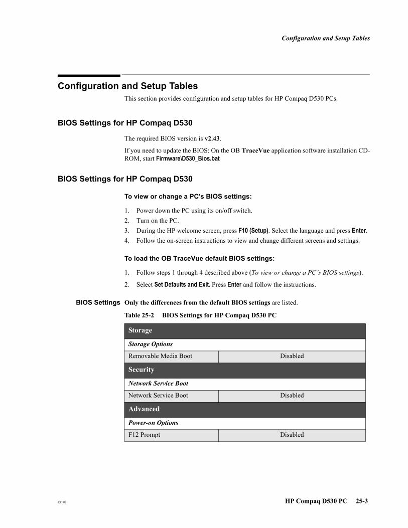
Configuration and Setup Tables
8081318 HP Compaq D530 PC 25-3
Configuration and Setup Tables
This section provides configuration and setup tables for HP Compaq D530 PCs.
BIOS Settings for HP Compaq D530
The required BIOS version is v2.43.
If you need to update the BIOS: On the OB TraceVue application software installation CD-ROM, start Firmware\D530_Bios.bat
BIOS Settings for HP Compaq D530
To view or change a PC's BIOS settings:
1. Power down the PC using its on/off switch.2. Turn on the PC.3. During the HP welcome screen, press F10 (Setup). Select the language and press Enter.4. Follow the on-screen instructions to view and change different screens and settings.
To load the OB TraceVue default BIOS settings:
1. Follow steps 1 through 4 described above (To view or change a PC’s BIOS settings).
2. Select Set Defaults and Exit. Press Enter and follow the instructions.
BIOS Settings Only the differences from the default BIOS settings are listed.
Table 25-2 BIOS Settings for HP Compaq D530 PC
Storage
Storage Options
Removable Media Boot Disabled
Security
Network Service Boot
Network Service Boot Disabled
Advanced
Power-on Options
F12 Prompt Disabled
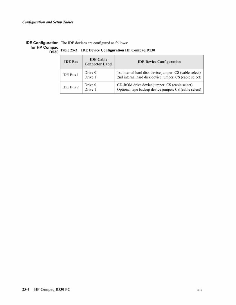
Configuration and Setup Tables
25-4 HP Compaq D530 PC 8081318
IDE Configurationfor HP Compaq
D530
The IDE devices are configured as follows:
Table 25-3 IDE Device Configuration HP Compaq D530
IDE Bus IDE Cable Connector Label IDE Device Configuration
IDE Bus 1 Drive 0Drive 1
1st internal hard disk device jumper: CS (cable select)2nd internal hard disk device jumper: CS (cable select)
IDE Bus 2 Drive 0Drive 1
CD-ROM drive device jumper: CS (cable select)Optional tape backup device jumper: CS (cable select)

Configuration and Setup Tables
8081318 HP Compaq D530 PC 25-5
SCSI BIOS Settings for HP Compaq D530
This section applies to server and standalone PCs fitted with the storage option. The SCSI BIOS is separate from the PC BIOS.
OB TraceVue requires the default SCSI BIOS settings. To ensure that these defaults are loaded:
1. Reboot the PC. Early in the HP welcome screen press ESC to get to the startup screen. Watch the screen carefully.
2. When the Symbios screen prompts you, early in the startup procedure, press F6.
3. In the main menu make sure SYM53C895 is selected, then press Enter.
4. Select Adapter Setup, then press Enter.
5. Select Restore Default Setup, then press Enter.
6. Save Changes.
Interrupt Adjustments for HP Compaq D530
All IRQs are auto-assigned. No manual configuration is necessary.

Configuration and Setup Tables
25-6 HP Compaq D530 PC 8081318
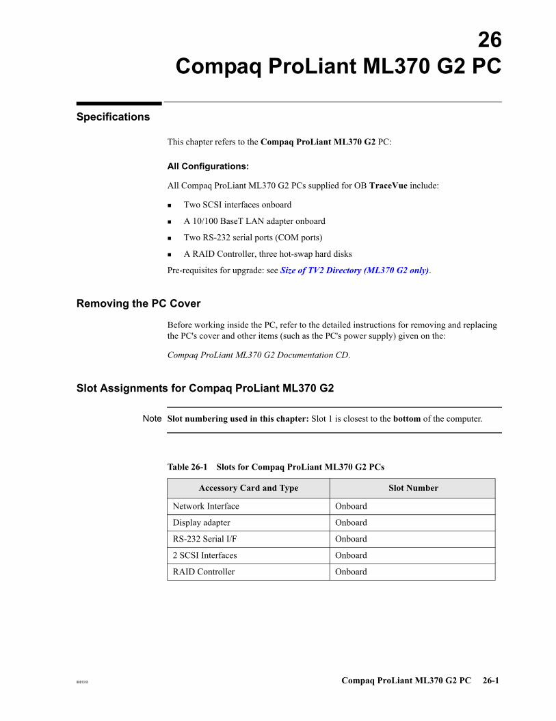
8081318 Compaq ProLiant ML370 G2 PC 26-1
26Compaq ProLiant ML370 G2 PC
Specifications
This chapter refers to the Compaq ProLiant ML370 G2 PC:
All Configurations:
All Compaq ProLiant ML370 G2 PCs supplied for OB TraceVue include:
Two SCSI interfaces onboard
A 10/100 BaseT LAN adapter onboard
Two RS-232 serial ports (COM ports)
A RAID Controller, three hot-swap hard disks
Pre-requisites for upgrade: see Size of TV2 Directory (ML370 G2 only).
Removing the PC Cover
Before working inside the PC, refer to the detailed instructions for removing and replacing the PC's cover and other items (such as the PC's power supply) given on the:
Compaq ProLiant ML370 G2 Documentation CD.
Slot Assignments for Compaq ProLiant ML370 G2
Note Slot numbering used in this chapter: Slot 1 is closest to the bottom of the computer.
Table 26-1 Slots for Compaq ProLiant ML370 G2 PCs
Accessory Card and Type Slot Number
Network Interface Onboard
Display adapter Onboard
RS-232 Serial I/F Onboard
2 SCSI Interfaces Onboard
RAID Controller Onboard
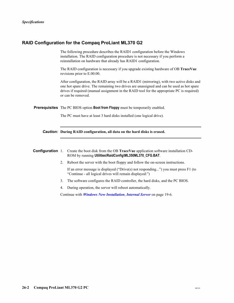
Specifications
26-2 Compaq ProLiant ML370 G2 PC 8081318
RAID Configuration for the Compaq ProLiant ML370 G2
The following procedure describes the RAID1 configuration before the Windows installation. The RAID configuration procedure is not necessary if you perform a reinstallation on hardware that already has RAID1 configuration.
The RAID configuration is necessary if you upgrade existing hardware of OB TraceVue revisions prior to E.00.00.
After configuration, the RAID array will be a RAID1 (mirroring), with two active disks and one hot spare drive. The remaining two drives are unassigned and can be used as hot spare drives if required (manual assignment in the RAID tool for the appropriate PC is required) or can be removed.
Prerequisites The PC BIOS option Boot from Floppy must be temporarily enabled.
The PC must have at least 3 hard disks installed (one logical drive).
Caution: During RAID configuration, all data on the hard disks is erased.
Configuration 1. Create the boot disk from the OB TraceVue application software installation CD-ROM by running Utilities\RaidConfig\ML350ML370_CFG.BAT.
2. Reboot the server with the boot floppy and follow the on-screen instructions.
If an error message is displayed (“Drive(s) not responding...”) you must press F1 (to “Continue - all logical drives will remain displayed:”)
3. The software configures the RAID controller, the hard disks, and the PC BIOS.
4. During operation, the server will reboot automatically.
Continue with Windows New Installation, Internal Server on page 19-6.

Configuration and Setup Tables
8081318 Compaq ProLiant ML370 G2 PC 26-3
Configuration and Setup Tables
This section provides configuration and setup tables for Compaq ProLiant ML370 G2 PCs.
BIOS Version for Compaq ProLiant ML370 G2
The required PC BIOS version is 4.07A (P25 05/01/2004).
The required RAID BIOS version is 2.62.
If necessary, create a BIOS update floppy from the OB TraceVue application software installation CD-ROM and install the required BIOS.
To upgrade the RAID BIOS, start the upgrade tool directly from the client CD in the folder Firmware\SmartArray_5i.
BIOS Settings for Compaq ProLiant ML370 G2
To view or change a PC's BIOS settings:
1. Power down the PC using its on/off switch.2. Turn on the PC.3. After the self-test, press F9.4. Follow the on-screen instructions to view and change different screens and settings
SCSI BIOS Settings for Compaq ProLiant ML370 G2
It is not possible to change SCSI BIOS settings.
Interrupt Adjustments for Compaq ProLiant ML370 G2
All IRQs are auto-assigned. No manual configuration is necessary.
PC and RAID BIOS Settings for Proliant ML370 G2
Do NOT change any BIOS settings.
Caution: If you change the RAID configuration settings, data on the ML370 will be lost.

Configuration and Setup Tables
26-4 Compaq ProLiant ML370 G2 PC 8081318
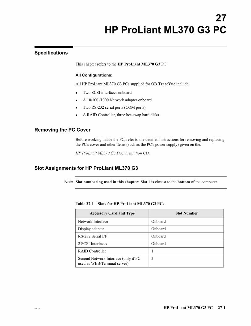
8081318 HP ProLiant ML370 G3 PC 27-1
27HP ProLiant ML370 G3 PC
Specifications
This chapter refers to the HP ProLiant ML370 G3 PC:
All Configurations:
All HP ProLiant ML370 G3 PCs supplied for OB TraceVue include:
Two SCSI interfaces onboard
A 10/100 /1000 Network adapter onboard
Two RS-232 serial ports (COM ports)
A RAID Controller, three hot-swap hard disks
Removing the PC Cover
Before working inside the PC, refer to the detailed instructions for removing and replacing the PC's cover and other items (such as the PC's power supply) given on the:
HP ProLiant ML370 G3 Documentation CD.
Slot Assignments for HP ProLiant ML370 G3
Note Slot numbering used in this chapter: Slot 1 is closest to the bottom of the computer.
Table 27-1 Slots for HP ProLiant ML370 G3 PCs
Accessory Card and Type Slot Number
Network Interface Onboard
Display adapter Onboard
RS-232 Serial I/F Onboard
2 SCSI Interfaces Onboard
RAID Controller 1
Second Network Interface (only if PC used as WEB/Terminal server)
5
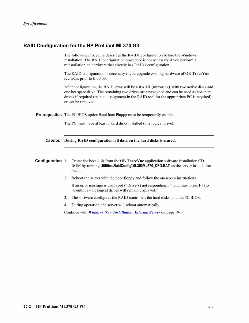
Specifications
27-2 HP ProLiant ML370 G3 PC 8081318
RAID Configuration for the HP ProLiant ML370 G3
The following procedure describes the RAID1 configuration before the Windows installation. The RAID configuration procedure is not necessary if you perform a reinstallation on hardware that already has RAID1 configuration.
The RAID configuration is necessary if you upgrade existing hardware of OB TraceVue revisions prior to E.00.00.
After configuration, the RAID array will be a RAID1 (mirroring), with two active disks and one hot spare drive. The remaining two drives are unassigned and can be used as hot spare drives if required (manual assignment in the RAID tool for the appropriate PC is required) or can be removed.
Prerequisites The PC BIOS option Boot from Floppy must be temporarily enabled.
The PC must have at least 3 hard disks installed (one logical drive).
Caution: During RAID configuration, all data on the hard disks is erased.
Configuration 1. Create the boot disk from the OB TraceVue application software installation CD-ROM by running Utilities\RaidConfig\ML350ML370_CFG.BAT on the server installation media.
2. Reboot the server with the boot floppy and follow the on-screen instructions.
If an error message is displayed (“Drive(s) not responding...”) you must press F1 (to “Continue - all logical drives will remain displayed:”)
3. The software configures the RAID controller, the hard disks, and the PC BIOS.
4. During operation, the server will reboot automatically.
Continue with Windows New Installation, Internal Server on page 19-6.
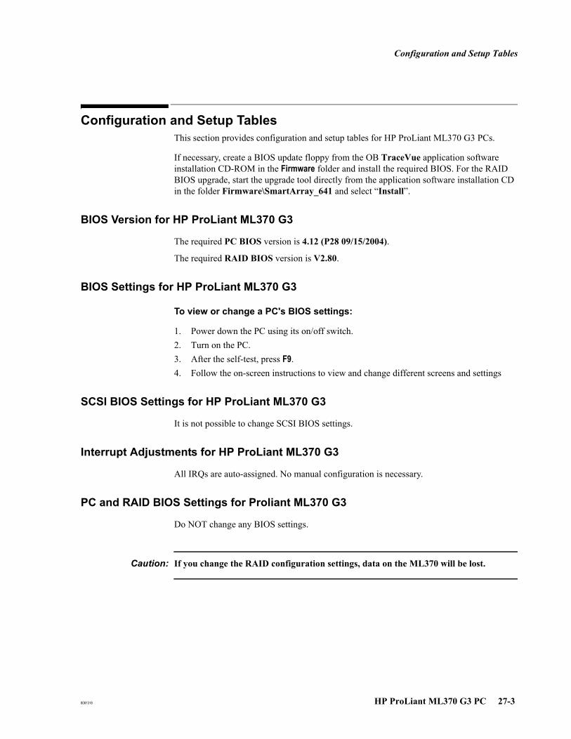
Configuration and Setup Tables
8081318 HP ProLiant ML370 G3 PC 27-3
Configuration and Setup Tables
This section provides configuration and setup tables for HP ProLiant ML370 G3 PCs.
If necessary, create a BIOS update floppy from the OB TraceVue application software installation CD-ROM in the Firmware folder and install the required BIOS. For the RAID BIOS upgrade, start the upgrade tool directly from the application software installation CD in the folder Firmware\SmartArray_641 and select “Install”.
BIOS Version for HP ProLiant ML370 G3
The required PC BIOS version is 4.12 (P28 09/15/2004).
The required RAID BIOS version is V2.80.
BIOS Settings for HP ProLiant ML370 G3
To view or change a PC's BIOS settings:
1. Power down the PC using its on/off switch.2. Turn on the PC.3. After the self-test, press F9.4. Follow the on-screen instructions to view and change different screens and settings
SCSI BIOS Settings for HP ProLiant ML370 G3
It is not possible to change SCSI BIOS settings.
Interrupt Adjustments for HP ProLiant ML370 G3
All IRQs are auto-assigned. No manual configuration is necessary.
PC and RAID BIOS Settings for Proliant ML370 G3
Do NOT change any BIOS settings.
Caution: If you change the RAID configuration settings, data on the ML370 will be lost.

Configuration and Setup Tables
27-4 HP ProLiant ML370 G3 PC 8081318
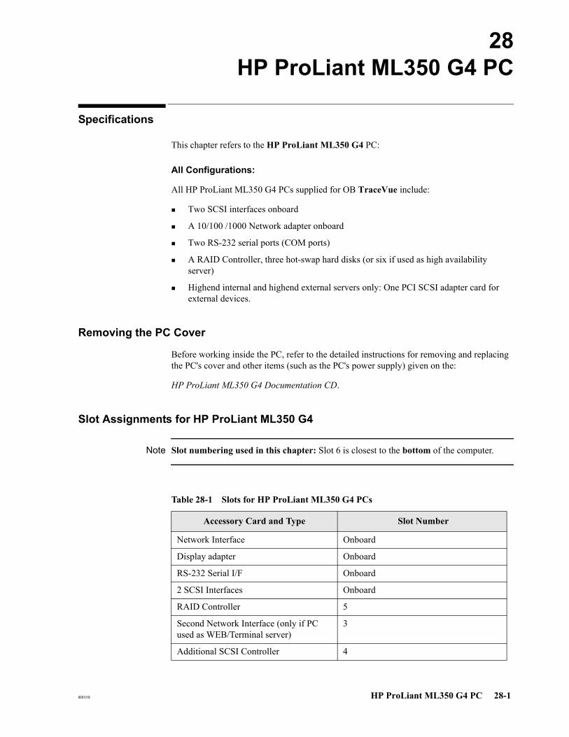
8081318 HP ProLiant ML350 G4 PC 28-1
28HP ProLiant ML350 G4 PC
Specifications
This chapter refers to the HP ProLiant ML350 G4 PC:
All Configurations:
All HP ProLiant ML350 G4 PCs supplied for OB TraceVue include:
Two SCSI interfaces onboard
A 10/100 /1000 Network adapter onboard
Two RS-232 serial ports (COM ports)
A RAID Controller, three hot-swap hard disks (or six if used as high availability server)
Highend internal and highend external servers only: One PCI SCSI adapter card for external devices.
Removing the PC Cover
Before working inside the PC, refer to the detailed instructions for removing and replacing the PC's cover and other items (such as the PC's power supply) given on the:
HP ProLiant ML350 G4 Documentation CD.
Slot Assignments for HP ProLiant ML350 G4
Note Slot numbering used in this chapter: Slot 6 is closest to the bottom of the computer.
Table 28-1 Slots for HP ProLiant ML350 G4 PCs
Accessory Card and Type Slot Number
Network Interface Onboard
Display adapter Onboard
RS-232 Serial I/F Onboard
2 SCSI Interfaces Onboard
RAID Controller 5
Second Network Interface (only if PC used as WEB/Terminal server)
3
Additional SCSI Controller 4
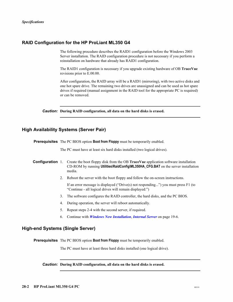
Specifications
28-2 HP ProLiant ML350 G4 PC 8081318
RAID Configuration for the HP ProLiant ML350 G4
The following procedure describes the RAID1 configuration before the Windows 2003 Server installation. The RAID configuration procedure is not necessary if you perform a reinstallation on hardware that already has RAID1 configuration.
The RAID1 configuration is necessary if you upgrade existing hardware of OB TraceVue revisions prior to E.00.00.
After configuration, the RAID array will be a RAID1 (mirroring), with two active disks and one hot spare drive. The remaining two drives are unassigned and can be used as hot spare drives if required (manual assignment in the RAID tool for the appropriate PC is required) or can be removed.
Caution: During RAID configuration, all data on the hard disks is erased.
High Availability Systems (Server Pair)
Prerequisites The PC BIOS option Boot from Floppy must be temporarily enabled.
The PC must have at least six hard disks installed (two logical drives).
Configuration 1. Create the boot floppy disk from the OB TraceVue application software installation CD-ROM by running Utilities\RaidConfig\ML350HA_CFG.BAT on the server installation media.
2. Reboot the server with the boot floppy and follow the on-screen instructions.
If an error message is displayed (“Drive(s) not responding...”) you must press F1 (to “Continue - all logical drives will remain displayed:”)
3. The software configures the RAID controller, the hard disks, and the PC BIOS.
4. During operation, the server will reboot automatically.
5. Repeat steps 2-4 with the second server, if required.
6. Continue with Windows New Installation, Internal Server on page 19-6.
High-end Systems (Single Server)
Prerequisites The PC BIOS option Boot from Floppy must be temporarily enabled.
The PC must have at least three hard disks installed (one logical drive).
Caution: During RAID configuration, all data on the hard disks is erased.

Specifications
8081318 HP ProLiant ML350 G4 PC 28-3
Configuration 1. Create the boot floppy disk from the OB TraceVue application software installation CD-ROM by running Utilities\RaidConfig\ML350ML370_CFG.BAT on the server installation media.
2. Reboot the server with the boot floppy and follow the on-screen instructions.
If an error message is displayed (“Drive(s) not responding...”) you must press F1 (to “Continue - all logical drives will remain displayed:”)
3. The software configures the RAID controller, the hard disks, and the PC BIOS.
4. During operation, the server will reboot automatically.
Continue with Windows New Installation, Internal Server on page 19-6.

Configuration and Setup Tables
28-4 HP ProLiant ML350 G4 PC 8081318
Configuration and Setup Tables
This section provides configuration and setup tables for HP ProLiant ML350 G4 PCs.
If necessary, create a BIOS update floppy from the OB TraceVue application software installation CD-ROM in the Firmware folder and install the required BIOS. For the RAID BIOS upgrade, start the upgrade tool directly from the application software installation CD in the folder Firmware\SmartArray_641 and select “Install”.
BIOS Version for HP ProLiant ML350 G4 (3.0 GHz)
The required PC BIOS version is D17 02/15/2006).
The required RAID BIOS version is V2.80.
BIOS Settings for HP ProLiant ML350 G4
To view or change a PC's BIOS settings:
1. Power down the PC using its on/off switch.2. Turn on the PC.3. After the self-test, press F9.4. Follow the on-screen instructions to view and change different screens and settings.

Configuration and Setup Tables
8081318 HP ProLiant ML350 G4 PC 28-5
SCSI BIOS Settings for HP Proliant ML350 G4
This section applies to a high-end internal and highend external server fitted with an additional PCI SCSI controller. The SCSI BIOS is separate from the PC BIOS.
OB TraceVue requires the default SCSI BIOS settings. To ensure that these defaults are loaded:
1. Reboot the PC. Watch the screen carefully.
2. When the Symbios screen prompts you, at the end of the startup procedure, press Ctrl + C.
3. In the main menu make sure SYM53C895A is selected, then press Enter.
4. Select Restore Default Setup, then press Enter.
5. Press Esc and save the changes.
Interrupt Adjustments for HP ProLiant ML350 G4
All IRQs are auto-assigned. No manual configuration is necessary.
PC and RAID BIOS Settings for Proliant ML350 G4
Do NOT change any BIOS settings.
Caution: If you change the RAID configuration settings, data on the ML350 will be lost.

Configuration and Setup Tables
28-6 HP ProLiant ML350 G4 PC 8081318
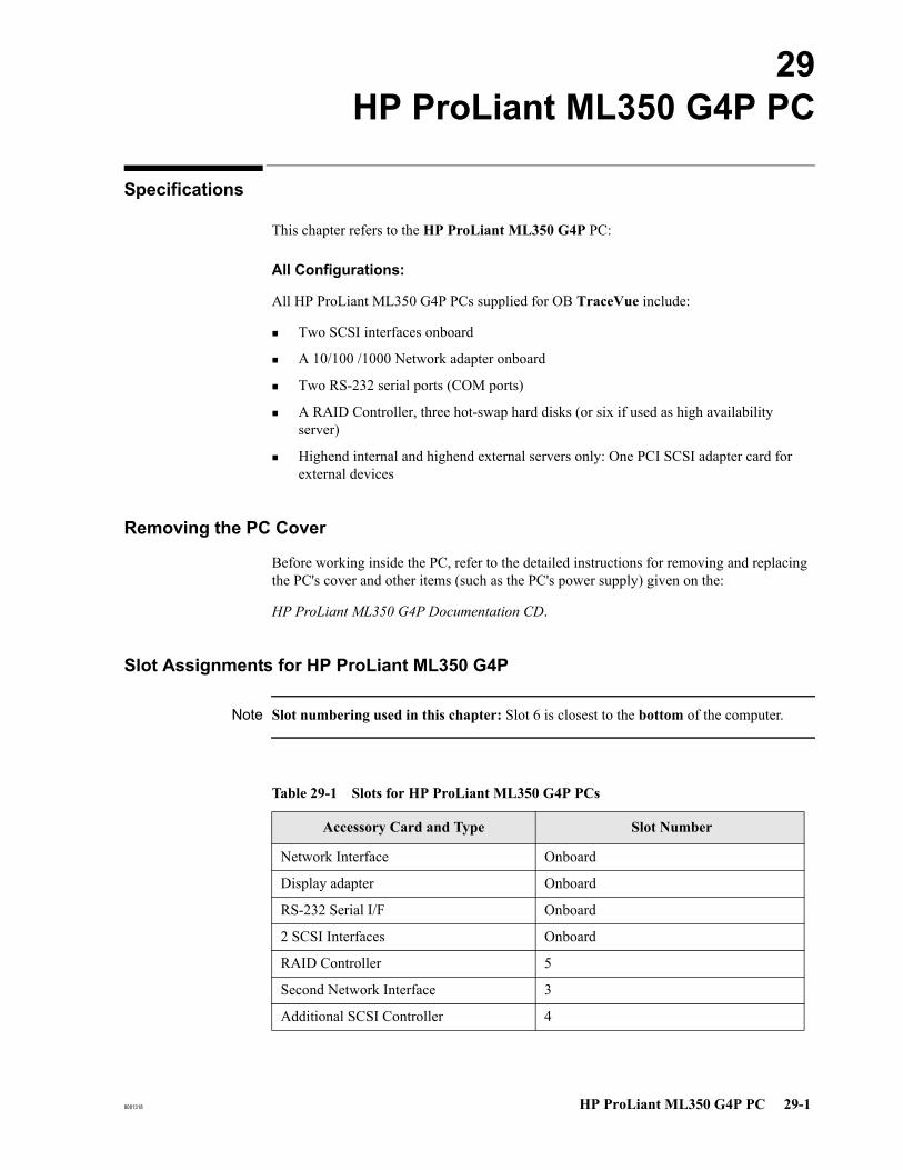
8081318 HP ProLiant ML350 G4P PC 29-1
29HP ProLiant ML350 G4P PC
Specifications
This chapter refers to the HP ProLiant ML350 G4P PC:
All Configurations:
All HP ProLiant ML350 G4P PCs supplied for OB TraceVue include:
Two SCSI interfaces onboard
A 10/100 /1000 Network adapter onboard
Two RS-232 serial ports (COM ports)
A RAID Controller, three hot-swap hard disks (or six if used as high availability server)
Highend internal and highend external servers only: One PCI SCSI adapter card for external devices
Removing the PC Cover
Before working inside the PC, refer to the detailed instructions for removing and replacing the PC's cover and other items (such as the PC's power supply) given on the:
HP ProLiant ML350 G4P Documentation CD.
Slot Assignments for HP ProLiant ML350 G4P
Note Slot numbering used in this chapter: Slot 6 is closest to the bottom of the computer.
Table 29-1 Slots for HP ProLiant ML350 G4P PCs
Accessory Card and Type Slot Number
Network Interface Onboard
Display adapter Onboard
RS-232 Serial I/F Onboard
2 SCSI Interfaces Onboard
RAID Controller 5
Second Network Interface 3
Additional SCSI Controller 4
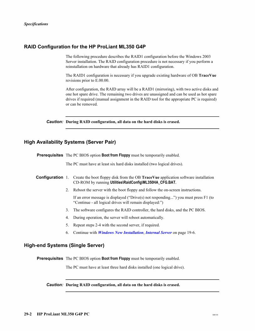
Specifications
29-2 HP ProLiant ML350 G4P PC 8081318
RAID Configuration for the HP ProLiant ML350 G4P
The following procedure describes the RAID1 configuration before the Windows 2003 Server installation. The RAID configuration procedure is not necessary if you perform a reinstallation on hardware that already has RAID1 configuration.
The RAID1 configuration is necessary if you upgrade existing hardware of OB TraceVue revisions prior to E.00.00.
After configuration, the RAID array will be a RAID1 (mirroring), with two active disks and one hot spare drive. The remaining two drives are unassigned and can be used as hot spare drives if required (manual assignment in the RAID tool for the appropriate PC is required) or can be removed.
Caution: During RAID configuration, all data on the hard disks is erased.
High Availability Systems (Server Pair)
Prerequisites The PC BIOS option Boot from Floppy must be temporarily enabled.
The PC must have at least six hard disks installed (two logical drives).
Configuration 1. Create the boot floppy disk from the OB TraceVue application software installation CD-ROM by running Utilities\RaidConfig\ML350HA_CFG.BAT.
2. Reboot the server with the boot floppy and follow the on-screen instructions.
If an error message is displayed (“Drive(s) not responding...”) you must press F1 (to “Continue - all logical drives will remain displayed:”)
3. The software configures the RAID controller, the hard disks, and the PC BIOS.
4. During operation, the server will reboot automatically.
5. Repeat steps 2-4 with the second server, if required.
6. Continue with Windows New Installation, Internal Server on page 19-6.
High-end Systems (Single Server)
Prerequisites The PC BIOS option Boot from Floppy must be temporarily enabled.
The PC must have at least three hard disks installed (one logical drive).
Caution: During RAID configuration, all data on the hard disks is erased.
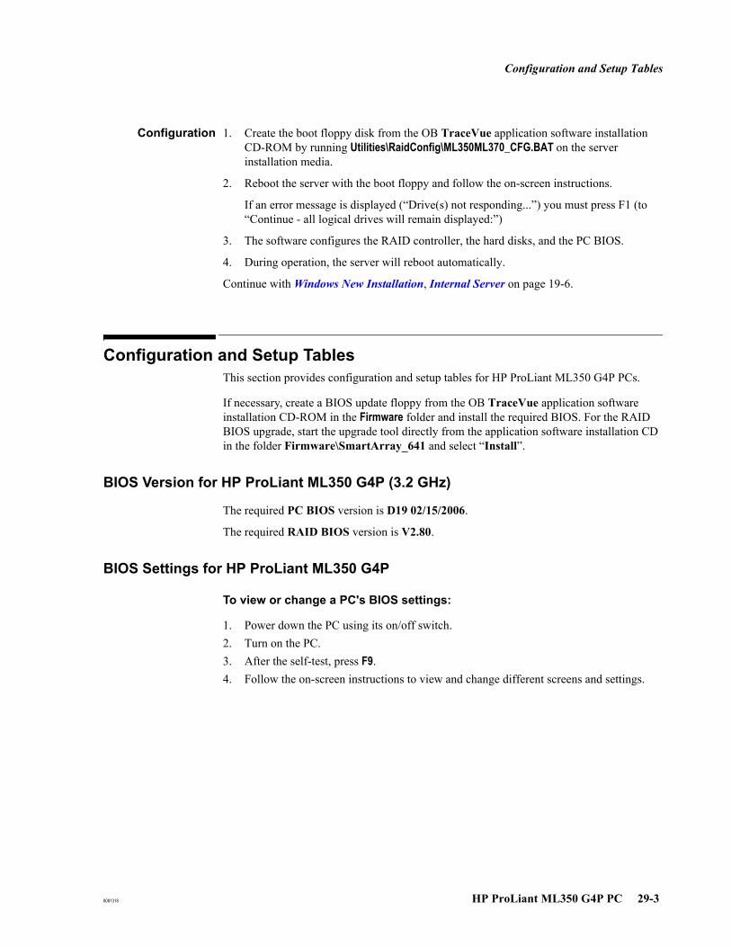
Configuration and Setup Tables
8081318 HP ProLiant ML350 G4P PC 29-3
Configuration 1. Create the boot floppy disk from the OB TraceVue application software installation CD-ROM by running Utilities\RaidConfig\ML350ML370_CFG.BAT on the server installation media.
2. Reboot the server with the boot floppy and follow the on-screen instructions.
If an error message is displayed (“Drive(s) not responding...”) you must press F1 (to “Continue - all logical drives will remain displayed:”)
3. The software configures the RAID controller, the hard disks, and the PC BIOS.
4. During operation, the server will reboot automatically.
Continue with Windows New Installation, Internal Server on page 19-6.
Configuration and Setup Tables This section provides configuration and setup tables for HP ProLiant ML350 G4P PCs.
If necessary, create a BIOS update floppy from the OB TraceVue application software installation CD-ROM in the Firmware folder and install the required BIOS. For the RAID BIOS upgrade, start the upgrade tool directly from the application software installation CD in the folder Firmware\SmartArray_641 and select “Install”.
BIOS Version for HP ProLiant ML350 G4P (3.2 GHz)
The required PC BIOS version is D19 02/15/2006.
The required RAID BIOS version is V2.80.
BIOS Settings for HP ProLiant ML350 G4P
To view or change a PC's BIOS settings:
1. Power down the PC using its on/off switch.2. Turn on the PC.3. After the self-test, press F9.4. Follow the on-screen instructions to view and change different screens and settings.
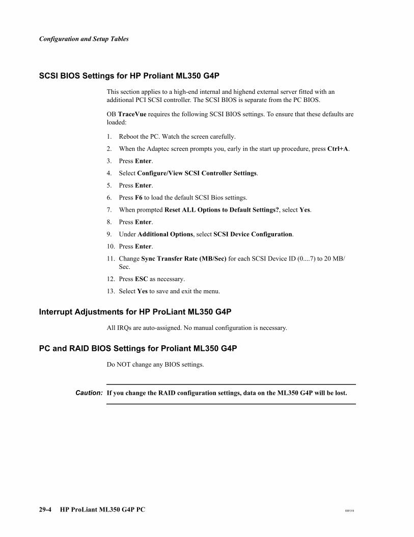
Configuration and Setup Tables
29-4 HP ProLiant ML350 G4P PC 8081318
SCSI BIOS Settings for HP Proliant ML350 G4P
This section applies to a high-end internal and highend external server fitted with an additional PCI SCSI controller. The SCSI BIOS is separate from the PC BIOS.
OB TraceVue requires the following SCSI BIOS settings. To ensure that these defaults are loaded:
1. Reboot the PC. Watch the screen carefully.
2. When the Adaptec screen prompts you, early in the start up procedure, press Ctrl+A.
3. Press Enter.
4. Select Configure/View SCSI Controller Settings.
5. Press Enter.
6. Press F6 to load the default SCSI Bios settings.
7. When prompted Reset ALL Options to Default Settings?, select Yes.
8. Press Enter.
9. Under Additional Options, select SCSI Device Configuration.
10. Press Enter.
11. Change Sync Transfer Rate (MB/Sec) for each SCSI Device ID (0....7) to 20 MB/Sec.
12. Press ESC as necessary.
13. Select Yes to save and exit the menu.
Interrupt Adjustments for HP ProLiant ML350 G4P
All IRQs are auto-assigned. No manual configuration is necessary.
PC and RAID BIOS Settings for Proliant ML350 G4P
Do NOT change any BIOS settings.
Caution: If you change the RAID configuration settings, data on the ML350 G4P will be lost.

8081318 HP ProLiant ML350 G5 PC 30-1
30HP ProLiant ML350 G5 PC
Specifications
This chapter refers to the HP ProLiant ML350 G5 PC:
All Configurations:
All HP ProLiant ML350 G5 PCs supplied for OB TraceVue include:
A 10/100 /1000 Network adapter onboard
Two RS-232 serial ports (COM ports)
A RAID Controller, three hot-swap hard disks (or six if used as high availability server)
Highend internal and highend external servers only: One PCI SCSI adapter card for external devices
Removing the PC Cover
Before working inside the PC, refer to the detailed instructions for removing and replacing the PC's cover and other items (such as the PC's power supply) given on the:
HP ProLiant ML350 G5 Documentation CD.
Slot Assignments for HP ProLiant ML350 G5
Note Slot numbering used in this chapter: See slot numbering on the rear panel of the computer.
Table 30-1 Slots for HP ProLiant ML350 G5 PCs
Accessory Card and Type Slot Number
Network Interface Onboard
Display adapter Onboard
RS-232 Serial I/F Onboard
RAID Controller Onboard
Second Network Interface 3
Additional SCSI Controller 2

Specifications
30-2 HP ProLiant ML350 G5 PC 8081318
RAID Configuration for the HP ProLiant ML350 G5
The following procedure describes the RAID1 configuration before the Windows 2003 Server installation. The RAID configuration procedure is not necessary if you perform a reinstallation on hardware that already has RAID1 configuration.
High-end Systems(Single Server)
Prerequisites
The PC must have at least three hard disks installed (one logical drive). Disk bays 1, 2, and 3 must be used.
Disk bays 4, 5, 6, 7, and 8 are equipped with hard drive blanks.
Caution: During RAID configuration, all data on the hard disks is erased.
Configuration 1. Start the PC, after the self-test when the screen shows Slot 0 HP Smart Array E200i Controller, and press F8.
2. Select Delete Logical Drive, and press Enter.
3. Press F8 to delete the logical drive and follow the instructions.
4. Select Create Logical Drive, and press Enter.
5. Under Available Physical Drives, uncheck Port 1I, Box 1, Bay 3.... by pressing the space bar.
6. Under RAID Configurations, select RAID 1+0.
7. Under Spare, select Use one drive as spare by pressing the space bar.
8. Under Maximum Boot partition, select Disable (4GB maximum). Press Enter and press F8 to save the configuration.
9. Continue with Windows New Installation, Internal Server on page 19-6.
Table 30-2 RAID Configuration
Disk Port Port 1I Port 2I
Disk Bay Bay 1 Bay 2 Bay 3 Bay 4 Bay 5 Bay 6 Bay 7 Bay 8
Logical Drive 1 Disk1 Disk2 Disk3
Spare
Drive
blank
Drive
blank
Drive blank
Drive blank
Drive blank
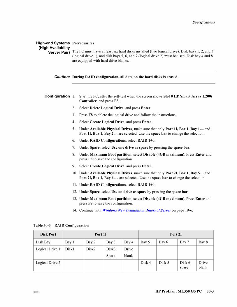
Specifications
8081318 HP ProLiant ML350 G5 PC 30-3
High-end Systems(High Availability
Server Pair)
Prerequisites
The PC must have at least six hard disks installed (two logical drive). Disk bays 1, 2, and 3 (logical drive 1), and disk bays 5, 6, and 7 (logical drive 2) must be used. Disk bay 4 and 8 are equipped with hard drive blanks.
Caution: During RAID configuration, all data on the hard disks is erased.
Configuration 1. Start the PC, after the self-test when the screen shows Slot 0 HP Smart Array E200i Controller, and press F8.
2. Select Delete Logical Drive, and press Enter.
3. Press F8 to delete the logical drive and follow the instructions.
4. Select Create Logical Drive, and press Enter.
5. Under Available Physical Drives, make sure that only Port 1I, Box 1, Bay 1.... and Port 1I, Box 1, Bay 2.... are selected. Use the space bar to change the selection.
6. Under RAID Configurations, select RAID 1+0.
7. Under Spare, select Use one drive as spare by pressing the space bar.
8. Under Maximum Boot partition, select Disable (4GB maximum). Press Enter and press F8 to save the configuration.
9. Select Create Logical Drive, and press Enter.
10. Under Available Physical Drives, make sure that only Port 2I, Box 1, Bay 5.... and Port 2I, Box 1, Bay 6..... are selected. Use the space bar to change the selection.
11. Under RAID Configurations, select RAID 1+0.
12. Under Spare, select Use on drive as spare by pressing the space bar.
13. Under Maximum Boot partition, select Disable (4GB maximum). Press Enter and press F8 to save the configuration.
14. Continue with Windows New Installation, Internal Server on page 19-6.
Table 30-3 RAID Configuration
Disk Port Port 1I Port 2I
Disk Bay Bay 1 Bay 2 Bay 3 Bay 4 Bay 5 Bay 6 Bay 7 Bay 8
Logical Drive 1 Disk1 Disk2 Disk3
Spare
Drive
blank
Logical Drive 2 Disk 4 Disk 5 Disk 6 spare
Drive blank
Configuration and Setup Tables
30-4 HP ProLiant ML350 G5 PC 8081318
Configuration and Setup Tables This section provides configuration and setup tables for HP ProLiant ML350 G5P PCs.
If necessary, create a BIOS update floppy from the OB TraceVue application software installation CD-ROM in the Firmware folder and install the required BIOS. For the RAID BIOS upgrade, start the upgrade tool directly from the application software installation CD in the folder Firmware\ML350G5\SmartArray_E200i and select “Install”.
BIOS Version for HP ProLiant ML350 G5
The required PC BIOS version is D21 01/24/2008.
The required RAID BIOS version is V1.72.
BIOS Settings for HP ProLiant ML350 G5
To view or change a PC's BIOS settings:
1. Power down the PC using its on/off switch.2. Turn on the PC.3. After the self-test, press F9.4. Follow the on-screen instructions to view and change different screens and settings.
To reset the BIOS settings to the Default Settings:
1. Follow steps 1 through 3 described above (To view or change a PC’s BIOS settings).
2. Select Advanced Option and press Enter.
3. Select Restore Default System Settings and press Enter twice.
4. Select Yes, Select to Restore and press Enter.
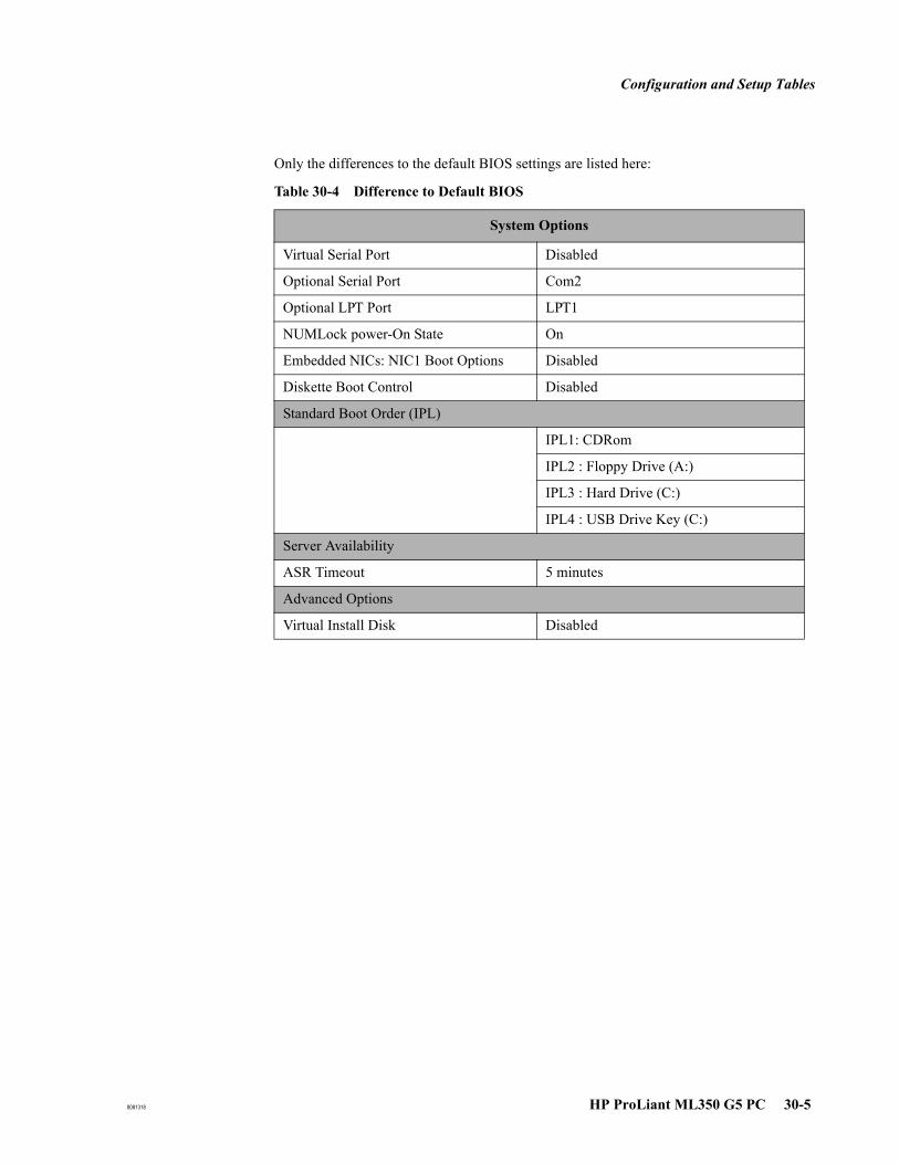
Configuration and Setup Tables
8081318 HP ProLiant ML350 G5 PC 30-5
Only the differences to the default BIOS settings are listed here:
Table 30-4 Difference to Default BIOS
System Options
Virtual Serial Port Disabled
Optional Serial Port Com2
Optional LPT Port LPT1
NUMLock power-On State On
Embedded NICs: NIC1 Boot Options Disabled
Diskette Boot Control Disabled
Standard Boot Order (IPL)
IPL1: CDRom
IPL2 : Floppy Drive (A:)
IPL3 : Hard Drive (C:)
IPL4 : USB Drive Key (C:)
Server Availability
ASR Timeout 5 minutes
Advanced Options
Virtual Install Disk Disabled
Configuration and Setup Tables
30-6 HP ProLiant ML350 G5 PC 8081318
SCSI BIOS Settings for HP Proliant ML350 G5
This section applies to a high-end internal and highend external server fitted with an additional PCI SCSI controller. The SCSI BIOS is separate from the PC BIOS.
OB TraceVue requires the following SCSI BIOS settings. To ensure that these defaults are loaded:
1. Reboot the PC. Watch the screen carefully.
2. When the Adaptec screen prompts you, early in the start up procedure, press Ctrl+A.
3. Press Enter.
4. Select Configure/View SCSI Controller Settings.
5. Press Enter.
6. Press F6 to load the default SCSI Bios settings.
7. When prompted Reset ALL Options to Default Settings?, select Yes.
8. Press Enter.
9. Under Additional Options, select SCSI Device Configuration.
10. Press Enter.
11. Change Sync Transfer Rate (MB/Sec) for each SCSI Device ID (0....7) to 20 MB/Sec.
12. Press ESC as necessary.
13. Select Yes to save and exit the menu.
Interrupt Adjustments for HP ProLiant ML350 G5
All IRQs are auto-assigned. No manual configuration is necessary.
PC and RAID BIOS Settings for Proliant ML350 G5
Do NOT change any BIOS settings.
Caution: If you change the RAID configuration settings, data on the ML350 G5 will be lost.

8081318 HP Compaq dc7100 PC 31-1
31HP Compaq dc7100 PC
Specifications
This chapter refers to the HP Compaq dc7100 CMT PC (M3167E)
All Configurations:
All HP Compaq dc7100 PCs supplied for OB TraceVue include:
A sound card onboard.
A 10/100/1000 BaseT LAN adapter onboard.
Two RS-232 serial ports (COM ports).
Optional Configurations:
HP Compaq dc7100 PCs supplied for OB TraceVue may be fitted with:
A PCI RS-232 Serial Interface that provides two additional COM ports, COM3 and COM4.
A second network interface card (only if PC is used as a WEB/Terminal Services PC or a non-data acquisition client).
Server only: A PCI SCSI adapter card. The patient data storage option adds an internal 2nd SATA hard disk, and either one, or two external optical disk drive(s).
Removing the PC Cover
Before working inside the PC, refer to the detailed instructions for removing and replacing the PC's cover and other items (such as the PC's power supply) given in the:
HP Compaq dc7100 Hardware Reference Guide on the Documentation Library CD.

Specifications
31-2 HP Compaq dc7100 PC 8081318
Slot Assignments for HP Compaq dc7100
Note Slot numbers marked on the backpanel or on the system board of the PC may differ from the slot numbering used in this chapter: Slot numbering in this chapter: Slot 1 is closest to the left of the computer (rear view).
.
Soundcard Settings for HP Compaq dc7100
The IRQ is auto-assigned. No manual configuration is necessary.
RS-232 I/F Card for HP Compaq dc7100
Two RS-232 COM Ports, Serial A and Serial B are built into the PC. A PCI RS-232 serial interface may be fitted to provide a total of four COM ports.
Table 31-1 Slots for HP Compaq dc7100 PCs
Accessory Card and Type Slot Number
Network Interface Onboard
Display adapter Onboard
RS-232 Serial I/F Onboard
Add. RS-232 Serial I/F 3
SCSI Interface (internal Server) 6
Second Network Interface (Web/Terminal
Server or non-dataacquisition client)
7
Sound Card Onboard

Configuration and Setup Tables
8081318 HP Compaq dc7100 PC 31-3
Configuration and Setup Tables
This section provides configuration and setup tables for HP Compaq dc7100 PCs.
BIOS Settings for HP Compaq dc7100
The required BIOS version is v2.14.
If you need to update the BIOS: On the OB TraceVue application software installation CD-ROM start Firmware\DC7100_Bios.bat
BIOS Settings for HP Compaq dc7100
To view or change a PC's BIOS settings:
1. Power down the PC using its on/off switch.2. Turn on the PC.3. During the HP welcome screen, press F10 (Setup). Select the language and press Enter.4. Follow the on-screen instructions to view and change different screens and settings.
To load the OB TraceVue default BIOS settings:
1. Follow steps 1 through 4 described above (To view or change a PC’s BIOS settings).
2. Select Apply Defaults and Exit. Press Enter and follow the instructions.
BIOS Settings Only the differences from the default BIOS settings are listed.
Table 31-2 BIOS Settings for HP Compaq dc7100 PC
Storage
Storage Options
Removable Media Boot Disabled
Security
Device Security
Front UsB Ports Device Hidden
Network Service Boot
Network Service Boot Disabled
Advanced
Power-on Options
F12 Prompt Disabled
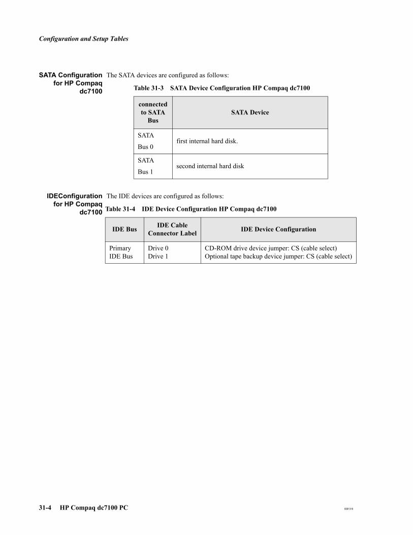
Configuration and Setup Tables
31-4 HP Compaq dc7100 PC 8081318
SATA Configurationfor HP Compaq
dc7100
The SATA devices are configured as follows:
IDEConfigurationfor HP Compaq
dc7100
The IDE devices are configured as follows:
Table 31-3 SATA Device Configuration HP Compaq dc7100
connected to SATA
BusSATA Device
SATA
Bus 0first internal hard disk.
SATA
Bus 1second internal hard disk
Table 31-4 IDE Device Configuration HP Compaq dc7100
IDE Bus IDE Cable Connector Label IDE Device Configuration
Primary IDE Bus
Drive 0Drive 1
CD-ROM drive device jumper: CS (cable select)Optional tape backup device jumper: CS (cable select)

Configuration and Setup Tables
8081318 HP Compaq dc7100 PC 31-5
SCSI BIOS Settings for HP Compaq dc7100
This section applies to server and standalone PCs fitted with the storage option. The SCSI BIOS is separate from the PC BIOS.
OB TraceVue requires the default SCSI BIOS settings. To ensure that these defaults are loaded:
1. Reboot the PC. Early in the HP welcome screen press ESC to get to the startup screen. Watch the screen carefully.
2. When the Symbios screen prompts you, early in the startup procedure, press Ctrl+C.
3. In the main menu make sure SYM53C895A is selected, then press Enter.
4. Select Restore Default Setup, then press Enter.
5. Press Esc and Save Changes.
Interrupt Adjustments for HP Compaq dc7100
All IRQs are auto-assigned. No manual configuration is necessary.

Configuration and Setup Tables
31-6 HP Compaq dc7100 PC 8081318
8081318 HP Compaq dc7600 PC 32-1
32HP Compaq dc7600 PC
Specifications
This chapter refers to the HP Compaq dc7600 CMT PC (M3167F, M3167G):
All Configurations:
All HP Compaq dc7600 PCs supplied for OB TraceVue include:
A sound card onboard.
A 10/100/1000 BaseT LAN adapter onboard.
Two RS-232 serial ports (COM ports).
Optional Configurations:
HP Compaq dc7600 PCs supplied for OB TraceVue may be fitted with:
A PCI RS-232 Serial Interface that provides two additional COM ports, COM3 and COM4.
A second network interface card (only if PC is used as a WEB/Terminal Services PC or a non-data acquisition client).
Server only: A PCI SCSI adapter card. The patient data storage option adds an internal 2nd SATA hard disk, and either one, or two external optical disk drive(s).
Removing the PC Cover
Before working inside the PC, refer to the detailed instructions for removing and replacing the PC's cover and other items (such as the PC's power supply) given in the:
HP Compaq dc7600 Hardware Reference Guide on the Documentation Library CD.

Specifications
32-2 HP Compaq dc7600 PC 8081318
Slot Assignments for HP Compaq dc7600
Note Slot numbers marked on the backpanel or on the system board of the PC may differ from the slot numbering used in this chapter: Slot numbering in this chapter: Slot 1 is closest to the left of the computer (rear view).
Soundcard Settings for HP Compaq dc7600
The IRQ is auto-assigned. No manual configuration is necessary.
RS-232 I/F Card for HP Compaq dc7600
Two RS-232 COM Ports, Serial A and Serial B are built into the PC. A PCI RS-232 serial interface may be fitted to provide a total of four COM ports.
Table 32-1 Slots for HP Compaq dc7600 PCs
Accessory Card and Type Slot Number
Network Interface Onboard
Display adapter Onboard
RS-232 Serial I/F Onboard
Add. RS-232 Serial I/F 31
1. It is not possible to have both due to mechanical conflicts
SCSI Interface (internal Server) 4
2nd Network Interface (Web/TerminalServer or non-dataacquisition client)
31
Sound Card Onboard

Configuration and Setup Tables
8081318 HP Compaq dc7600 PC 32-3
Configuration and Setup Tables
This section provides configuration and setup tables for HP Compaq dc7600 PCs.
BIOS Settings for HP Compaq dc7600
The required BIOS version is v1.59.
If you need to update the BIOS: Using Windows Explorer, start Firmware\DC7600\HPQFlash.exe from the OB TraceVue application software installation CD-ROM.
BIOS Settings for HP Compaq dc7600
To view or change a PC's BIOS settings:
1. Power down the PC using its on/off switch.2. Turn on the PC.3. During the HP welcome screen, press F10 (Setup). Select the language and press Enter.4. Follow the on-screen instructions to view and change different screens and settings.
To load the OB TraceVue default BIOS settings:
1. Follow steps 1 through 4 described above (To view or change a PC’s BIOS settings).
2. Select Apply Defaults and Exit. Press Enter and follow the instructions.

Configuration and Setup Tables
32-4 HP Compaq dc7600 PC 8081318
BIOS Settings Only the differences from the default BIOS settings are listed.
SATA Configurationfor HP Compaq
dc7600
The SATA devices are configured as follows:
Table 32-2 BIOS Settings for HP Compaq dc7600 PC
Storage
Storage Options
Removable Media Boot Disabled
Boot Order
Diskette Drive
ATAPI CD-ROM Drive
Hard Drive - Integrated SATA
Hard Drive - Integrated IDE
Broadcom Ethernet controller Disabled
Optional Intel Ethernet controller Disabled
USB device Disabled
Security
Device Security
Front UsB Ports Device Hidden
Network Service Boot
Network Service Boot Disabled
Advanced
Power-on Options
F12 Prompt Hidden
Table 32-3 SATA Device Configuration HP Compaq dc7600
connected to SATA
BusSATA Device
SATA
Bus 0first internal hard disk.
SATA
Bus 1second internal hard disk
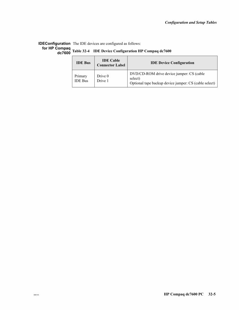
Configuration and Setup Tables
8081318 HP Compaq dc7600 PC 32-5
IDEConfigurationfor HP Compaq
dc7600
The IDE devices are configured as follows:
Table 32-4 IDE Device Configuration HP Compaq dc7600
IDE Bus IDE Cable Connector Label IDE Device Configuration
Primary IDE Bus
Drive 0Drive 1
DVD/CD-ROM drive device jumper: CS (cable select)Optional tape backup device jumper: CS (cable select)
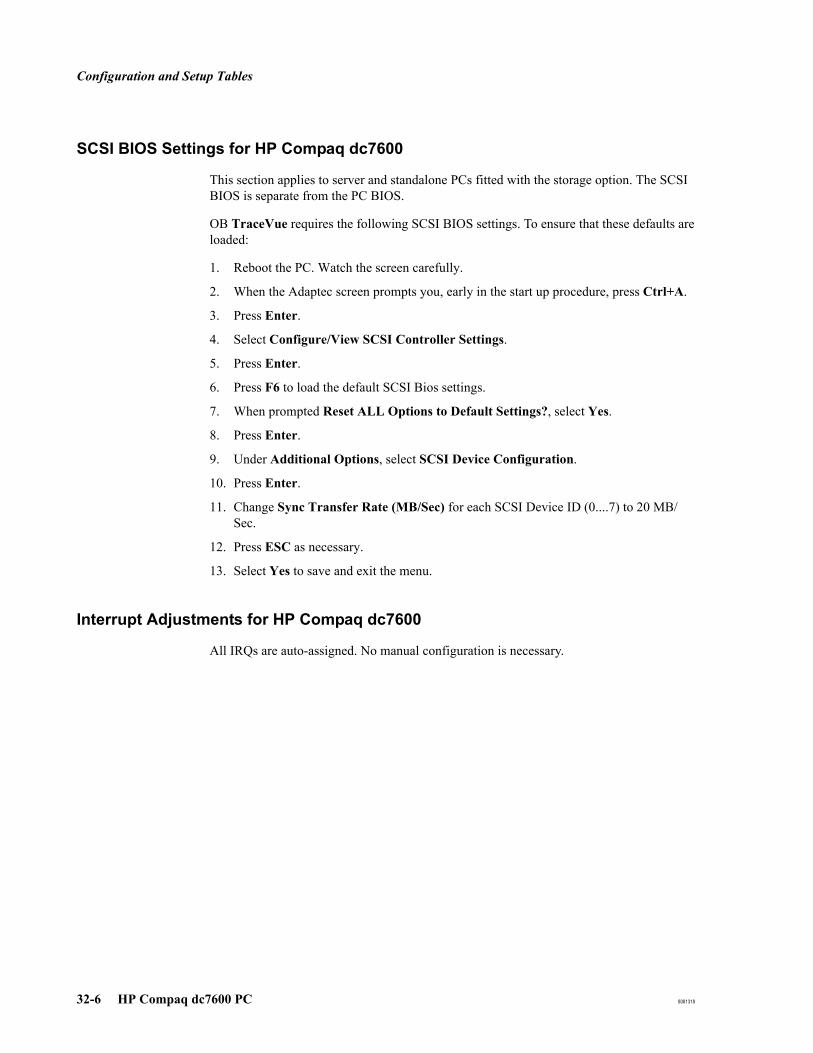
Configuration and Setup Tables
32-6 HP Compaq dc7600 PC 8081318
SCSI BIOS Settings for HP Compaq dc7600
This section applies to server and standalone PCs fitted with the storage option. The SCSI BIOS is separate from the PC BIOS.
OB TraceVue requires the following SCSI BIOS settings. To ensure that these defaults are loaded:
1. Reboot the PC. Watch the screen carefully.
2. When the Adaptec screen prompts you, early in the start up procedure, press Ctrl+A.
3. Press Enter.
4. Select Configure/View SCSI Controller Settings.
5. Press Enter.
6. Press F6 to load the default SCSI Bios settings.
7. When prompted Reset ALL Options to Default Settings?, select Yes.
8. Press Enter.
9. Under Additional Options, select SCSI Device Configuration.
10. Press Enter.
11. Change Sync Transfer Rate (MB/Sec) for each SCSI Device ID (0....7) to 20 MB/Sec.
12. Press ESC as necessary.
13. Select Yes to save and exit the menu.
Interrupt Adjustments for HP Compaq dc7600
All IRQs are auto-assigned. No manual configuration is necessary.
8081318 HP Compaq dc7700 PC 33-1
33HP Compaq dc7700 PC
Specifications
This chapter refers to the HP Compaq dc7700 CMT PC:
All Configurations:
All HP Compaq dc7700 PCs supplied for OB TraceVue include:
A sound card onboard.
A 10/100/1000 BaseT LAN adapter onboard.
Two RS-232 serial ports (COM ports).
Optional Configurations:
HP Compaq dc7700 PCs supplied for OB TraceVue may be fitted with:
A PCI RS-232 Serial Interface that provides two additional COM ports, COM3 and COM4.
A second network interface card (only if PC is used as a WEB/Terminal Services PC or a non-data acquisition client).
Server only: A PCI SCSI adapter card. The patient data storage option adds an internal 2nd SATA hard disk, and either one, or two external optical disk drive(s).
Removing the PC Cover
Before working inside the PC, refer to the detailed instructions for removing and replacing the PC's cover and other items (such as the PC's power supply) given in the:
HP Compaq dc7700 Hardware Reference Guide on the Documentation and Diagnostics CD.
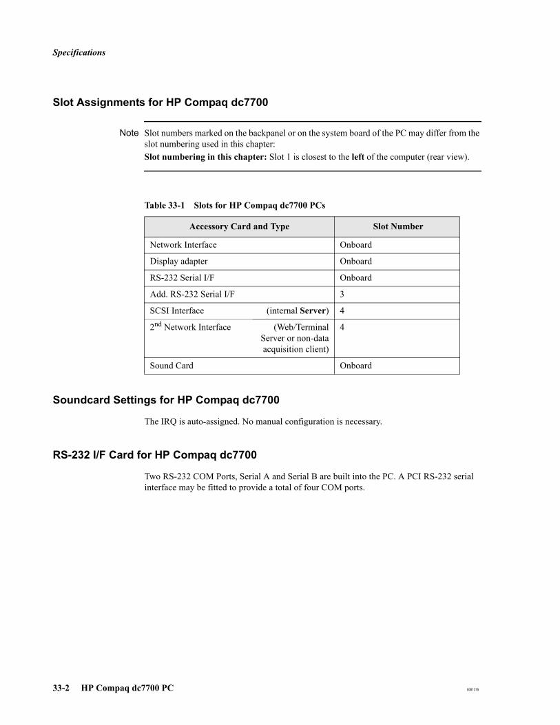
Specifications
33-2 HP Compaq dc7700 PC 8081318
Slot Assignments for HP Compaq dc7700
Note Slot numbers marked on the backpanel or on the system board of the PC may differ from the slot numbering used in this chapter: Slot numbering in this chapter: Slot 1 is closest to the left of the computer (rear view).
Soundcard Settings for HP Compaq dc7700
The IRQ is auto-assigned. No manual configuration is necessary.
RS-232 I/F Card for HP Compaq dc7700
Two RS-232 COM Ports, Serial A and Serial B are built into the PC. A PCI RS-232 serial interface may be fitted to provide a total of four COM ports.
Table 33-1 Slots for HP Compaq dc7700 PCs
Accessory Card and Type Slot Number
Network Interface Onboard
Display adapter Onboard
RS-232 Serial I/F Onboard
Add. RS-232 Serial I/F 3
SCSI Interface (internal Server) 4
2nd Network Interface (Web/TerminalServer or non-dataacquisition client)
4
Sound Card Onboard
Configuration and Setup Tables
8081318 HP Compaq dc7700 PC 33-3
Configuration and Setup Tables
This section provides configuration and setup tables for HP Compaq dc7700 PCs.
BIOS Version for HP Compaq dc7700
The required BIOS version is v1.14.
If you need to update the BIOS: Using Windows Explorer, start Firmware\DC7700\HPQFlash.exe from the OB TraceVue application software installation CD-ROM.
BIOS Settings for HP Compaq dc7700
To view or change a PC's BIOS settings:
1. Power down the PC using its on/off switch.2. Turn on the PC.3. During the HP welcome screen, press F10 (Setup). Select the language and press Enter.4. Follow the on-screen instructions to view and change different screens and settings.
To load the OB TraceVue default BIOS settings:
1. Follow steps 1 through 4 described above (To view or change a PC’s BIOS settings).
2. Select Apply Defaults and Exit. Press Enter and follow the instructions.
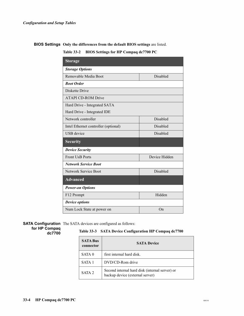
Configuration and Setup Tables
33-4 HP Compaq dc7700 PC 8081318
BIOS Settings Only the differences from the default BIOS settings are listed.
SATA Configurationfor HP Compaq
dc7700
The SATA devices are configured as follows:
Table 33-2 BIOS Settings for HP Compaq dc7700 PC
Storage
Storage Options
Removable Media Boot Disabled
Boot Order
Diskette Drive
ATAPI CD-ROM Drive
Hard Drive - Integrated SATA
Hard Drive - Integrated IDE
Network controller Disabled
Intel Ethernet controller (optional) Disabled
USB device Disabled
Security
Device Security
Front UsB Ports Device Hidden
Network Service Boot
Network Service Boot Disabled
Advanced
Power-on Options
F12 Prompt Hidden
Device options
Num Lock State at power on On
Table 33-3 SATA Device Configuration HP Compaq dc7700
SATA Bus connector SATA Device
SATA 0 first internal hard disk.
SATA 1 DVD/CD-Rom drive
SATA 2 Second internal hard disk (internal server) or backup device (external server)

Configuration and Setup Tables
8081318 HP Compaq dc7700 PC 33-5
Sata Backup Devicedc7700
Do not use the backup software included with the tape drive. Use the Windows backup software as described in the External Database Guide.
SCSI BIOS Settings for HP Compaq dc7700
This section applies to server and standalone PCs fitted with the storage option. The SCSI BIOS is separate from the PC BIOS.
OB TraceVue requires the following SCSI BIOS settings. To ensure that these defaults are loaded:
1. Reboot the PC. Watch the screen carefully.
2. When the Adaptec screen prompts you, early in the start up procedure, press Ctrl+A.
3. Press Enter.
4. Select Configure/View SCSI Controller Settings.
5. Press Enter.
6. Press F6 to load the default SCSI Bios settings.
7. When prompted Reset ALL Options to Default Settings?, select Yes.
8. Press Enter.
9. Under Additional Options, select SCSI Device Configuration.
10. Press Enter.
11. Change Sync Transfer Rate (MB/Sec) for each SCSI Device ID (0....7) to 20 MB/Sec.
12. Press ESC as necessary.
13. Select Yes to save and exit the menu.
Interrupt Adjustments for HP Compaq dc7700
All IRQs are auto-assigned. No manual configuration is necessary.

Configuration and Setup Tables
33-6 HP Compaq dc7700 PC 8081318
8081318 HP rp5700 PC 34-1
34HP rp5700 PC
Specifications
This chapter refers to the HP rp5700 PC:
All Configurations:
All HP rp5700 PCs supplied for OB TraceVue include:
A sound card onboard.
A 10/100 BaseT LAN adapter onboard.
Two RS-232 serial ports (COM ports).
Optional Configurations:
HP rp5700 PCs supplied for OB TraceVue may be fitted with:
A PCI RS-232 Serial Interface that provides two additional COM ports, COM3 and COM4.
A second network interface card.
Internal Server with archiving only: A PCI SCSI adapter card. The patient data storage option adds an internal 2nd SATA hard disk, and either one, or two external optical disk drive(s).
Removing the PC Cover
Before working inside the PC, refer to the detailed instructions for removing and replacing the PC's cover and other items (such as the PC's power supply) given in the:
HP rp5700 Documentation and Diagnostics CD.
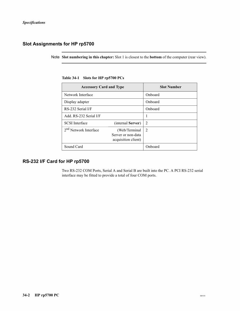
Specifications
34-2 HP rp5700 PC 8081318
Slot Assignments for HP rp5700
Note Slot numbering in this chapter: Slot 1 is closest to the bottom of the computer (rear view).
RS-232 I/F Card for HP rp5700
Two RS-232 COM Ports, Serial A and Serial B are built into the PC. A PCI RS-232 serial interface may be fitted to provide a total of four COM ports.
Table 34-1 Slots for HP rp5700 PCs
Accessory Card and Type Slot Number
Network Interface Onboard
Display adapter Onboard
RS-232 Serial I/F Onboard
Add. RS-232 Serial I/F 1
SCSI Interface (internal Server) 2
2nd Network Interface (Web/TerminalServer or non-dataacquisition client)
2
Sound Card Onboard
Configuration and Setup Tables
8081318 HP rp5700 PC 34-3
Configuration and Setup Tables
This section provides configuration and setup tables for HP rp5700 PCs.
BIOS Version for HP rp5700
The required BIOS version is V1.03 or v1.05.
If you need to update the BIOS: Using Windows Explorer, start Firmware\RP5700\HPQFlash.exe from the OB TraceVue application software installation CD-ROM.
BIOS Settings for HP rp5700
To view or change a PC's BIOS settings:
1. Power down the PC using its on/off switch.2. Turn on the PC.3. During the HP welcome screen, press F10 (Setup). Select the language and press Enter.4. Follow the on-screen instructions to view and change different screens and settings.
To reset the BIOS settings to the default settings:
1. Follow steps 1 through 4 described above (To view or change a PC’s BIOS settings).
2. Select Apply Defaults and Exit. Press Enter and follow the instructions.
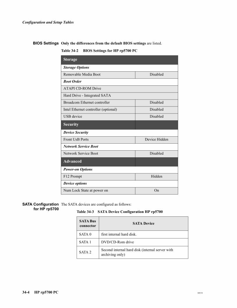
Configuration and Setup Tables
34-4 HP rp5700 PC 8081318
BIOS Settings Only the differences from the default BIOS settings are listed.
SATA Configurationfor HP rp5700
The SATA devices are configured as follows:
Table 34-2 BIOS Settings for HP rp5700 PC
Storage
Storage Options
Removable Media Boot Disabled
Boot Order
ATAPI CD-ROM Drive
Hard Drive - Integrated SATA
Broadcom Ethernet controller Disabled
Intel Ethernet controller (optional) Disabled
USB device Disabled
Security
Device Security
Front UsB Ports Device Hidden
Network Service Boot
Network Service Boot Disabled
Advanced
Power-on Options
F12 Prompt Hidden
Device options
Num Lock State at power on On
Table 34-3 SATA Device Configuration HP rp5700
SATA Bus connector SATA Device
SATA 0 first internal hard disk.
SATA 1 DVD/CD-Rom drive
SATA 2 Second internal hard disk (internal server with archiving only)

Configuration and Setup Tables
8081318 HP rp5700 PC 34-5
External ServerUSB Backup Device
rp5700
Do not use the backup software included with the tape drive. Use the Windows backup software as described in the External Database Guide.
SCSI BIOS Settings for HP rp5700
This section applies to server and standalone PCs fitted with the storage option. The SCSI BIOS is separate from the PC BIOS.
OB TraceVue requires the following SCSI BIOS settings. To ensure that these defaults are loaded:
1. Reboot the PC. Watch the screen carefully.
2. When the Adaptec screen prompts you, early in the start up procedure, press Ctrl+A.
3. Press Enter.
4. Select Configure/View SCSI Controller Settings.
5. Press Enter.
6. Press F6 to load the default SCSI Bios settings.
7. When prompted Reset ALL Options to Default Settings?, select Yes.
8. Press Enter.
9. Under Additional Options, select SCSI Device Configuration.
10. Press Enter.
11. Change Sync Transfer Rate (MB/Sec) for each SCSI Device ID (0....7) to 20 MB/Sec.
12. Press ESC as necessary.
13. Select Yes to save and exit the menu.
Interrupt Adjustments for HP rp5700
All IRQs are auto-assigned. No manual configuration is necessary.

Configuration and Setup Tables
34-6 HP rp5700 PC 8081318

8081318 A-1
AFetal Monitor Connections
Overview
OB TraceVue accepts the digital signal protocol used by HP/Agilent/Philips Series 50 and Avalon FM20/FM30/FM40/FM50 Fetal Monitors. Connecting these monitors to OB TraceVue is detailed in Chapter 5, New System Setup.
You can connect many other types of fetal monitor to OB TraceVue but they require special cable connectors to convert their signals to the digital protocol accepted by OB TraceVue. This is called a Protocol Conversion Kit. When OB TraceVue recognizes the monitor it can accept its data and even identify the monitor model and manufacturer. Every fetal monitor connected to OB TraceVue requires its own protocol converter. Cables and converters supplied by Philips have full Philips support, as defined in the Integration Guide.
OB TraceVue supports only those features that are part of the Series 50/Avalon Fetal Monitor. If your customer has a monitor that measures parameters other than those measured by Series 50/Avalon monitors, OB TraceVue cannot display them.
If a third party manufacturer claims compliance with the Philips digital signal protocol, responsibility for this compliance lies with that manufacturer. Connection of any third party fetal monitor is subject to “unapproved limited support” and requires integration testing. See the Integration Guide for further details.
Conversion Kits
Protocol Conversion Kits are available for many fetal monitors. The kit consists of:
Protocol Converter Box - to modify protocol.
Adapter Cable to identify manufacturer.
If for any reason you customize an adapter cable, this may prevent the manufacturer's identity being transmitted accurately.
A general purpose protocol conversion kit is also available. This converts analog signals to digital but does allow OB TraceVue to identify the monitor type.
Protocol Converter Box
This is a small box that contains the signal protocol converter. The DIL switch settings identify the model of fetal monitor to the protocol converter.
A digital to digital converter box has a single row of DIL switches. An analog to digital converter has a double row of DIL switches. This second row specifies the voltage range and offset necessary for correct conversion.
The protocol converter connects to a serial port on an OB TraceVue PC using a cable fitted with 9-pin sub-D connectors.

Conversion Kits
A-2 8081318
Adapter Cable
A 250mm (10 inch) adapter cable connects the fetal monitor to the protocol converter. This cable identifies the manufacturer of the fetal monitor to the protocol converter, and is fitted at the factory with the correct connectors. The adapter cable is necessary because even monitors from the same manufacturer may use different analog protocols which means that you cannot just have a manufacturer specific converter box.
Available Protocol Conversion Kits and Cables
The following kits are available. Note that cable part numbers are printed on the cables.
Table 34-4 Protocol Conversion Kits and Cables
Monitor Type Option No Cabling Replacement
part number Kit Contents
FM 2 #K10 M1380-61624 453563278221 RS-232 bedside cable
M1380-60624 451261010081 Adapter: Dsub 9 female to RJ45 female
HP 8040A #K11 M1380-63201 453563278231 Digital converter
M1380-61612 453563278111 RS-232 cable
M1380-60612 451261010061 Adapter: Dsub 9 male to RJ45 female
M1380-61609 453563278091 8040 adapter cable
0510-1334 453563023441 (Velcro) Fastener
Series 50 IX/XM/XMO (M1350A/B/C) (with RS232 interface only)
Avalon FM20 / FM30 / FM40 / FM50
#K12 M1380-61612 453563278111 RS-232 bedside cable
M1380-60612 451261010061 Adapter: Dsub 9 male to RJ45 female
Series 50 A/IP (M1351A/53A)
#K13 M1380-61613 453563278121 RS-232 bedside cable
M1380-60613 451261010071 Adapter: Centronics to RJ45 female

Conversion Kits
8081318 A-3
All settings are already adjusted at the factory.
Mounting the Protocol Converter
Find a convenient position to mount the protocol converter. The best place to mount the converter is on the fetal monitor itself, because the adapter cable and protocol converter are set to the fetal monitor type, and should remain with it. Make sure the fetal monitor’s ventilation holes are not obscured and the cabling is not strained or kinked. Mount the protocol converter using the velcro patch provided.
Corometrics 116, 118 #K21 M1380-63201 453563278231 Digital converter
M1380-61612 453563278111 RS-232 cable
M1380-60612 451261010061 Adapter: Dsub 9 male to RJ45 female
M1380-61618 453563278161 Corometrics digital adapter cable
0510-1334 453563023441 (Velcro) Fastener
Sonicaid Meridian 800 and Team
#K22 M1380-63201 453563278231 Digital converter
M1380-61612 453563278111 RS-232 cable
M1380-60612 451261010061 Adapter: Dsub 9 male to RJ45 female
M1380-61619 453563278171 Sonicaid digital adapter cable
0510-1334 453563023441 (Velcro) Fastener
Corometrics 129 or
Corometrics Series 120
#K23 M1380-61622 453563278201 RS-232 bedside cable
Corometrics 111, 112, 115, 115D, 145
#K31 M1380-63202 453563278241 Analog converter
M1380-61612 453563278111 RS-232 cable
M1380-60612 451261010061 Adapter: Dsub 9 male to RJ45 female
M1380-61614 453563278131 Corometrics analog adapter cable
0510-1334 453563023441 (Velcro) Fastener
Table 34-4 Protocol Conversion Kits and Cables
Monitor Type Option No Cabling Replacement
part number Kit Contents

Conversion Kits
A-4 8081318
Disconnecting a Fetal Monitor from OB TraceVue
If you need to disconnect the fetal monitor from the OB TraceVue PC, disconnect only one end of the RS-232 cable. It does not matter which. In this way, the adapter cable and protocol converter (if fitted) remain with the fetal monitor for which they are setup.

Data Tables for Supported Fetal Monitors
8081318 A-5
Data Tables for Supported Fetal MonitorsAll monitors listed support C-Request, GO mode, Halt, and I/D Request. In the following tables, s means that the switch should be set to up (on). t means it should be set to down (off). X indicates that the setting is not important.
There is only one bank of DIL switches on a digital protocol converter. There are two banks of switches on an analog protocol converter. The following diagram indicates the position of the banks of DIL switches.
Figure 34-1DIL Switch Location
HP 8040A
Use Protocol Conversion Kit 865072 #K11.
The supported data are:
FHR1 (red, yellow and green quality).
FHR2 or MECG (red and green quality).
TOCO.
Marker pressed.
Recorder on/off, paper speed, paper type.
<Figure entity=dilswitch>

Data Tables for Supported Fetal Monitors
A-6 8081318
Special requirements:
Digital interface must be fitted.
Table 34-5 HP 8040A - Digital Protocol Converter DIL Switch Settings
DIL Switch Settings
1 2 3 4 5 6 7 8
X X X X X X X X

Data Tables for Supported Fetal Monitors
8081318 A-7
Corometrics FM 115
Use Protocol Conversion Kit 865072 #K31.
The supported data are:
HR1 (red and green quality).
TOCO.
Marker pressed.
Corometrics FM 115D
Use Protocol Conversion Kit 865072 #K31.
The supported data are:
HR1 (red and green quality).
HR2 or MECG (red and green quality).
TOCO.
Marker pressed.
Table 34-6 Corometrics 115 - Analog Protocol Converter DIL Switch Settings
DIL Switch
Switch Settings
1 2 3 4 5 6 7 8
1 X X X t s s t s
2 s t t t s t s t
Table 34-7 Corometrics 115 twin (with dual HR) - Analog Protocol Converter DIL Switch Settings
DIL Switch
Switch Settings
1 2 3 4 5 6 7 8
1 X X X t t t s s
2 s t s t s t t t

Data Tables for Supported Fetal Monitors
A-8 8081318
Corometrics FM 116
Use Protocol Conversion Kit 865072 #K21.
The supported data are:
HR1 (red and green quality).
HR2 or MECG (red and green quality).
TOCO.
Notes; data from external maternal monitors.
Marker pressed.
Special Requirements
Configure the interface to 115 update mode, 9600 baud, no parity. See the service manual for the monitor for details about how to configure the interface.
Corometrics FM 118
Use Protocol Conversion Kit 865072 #K21.
The supported data are:
HR1 (red and green quality).
HR2 or MECG (red and green quality).
TOCO.
Notes; data from internal and external maternal monitors.
Marker pressed.
Table 34-8 Corometrics 116 - Digital Protocol Converter DIL Switch Settings
DIL Switch Settings
1 2 3 4 5 6 7 8
X X X t t t s t
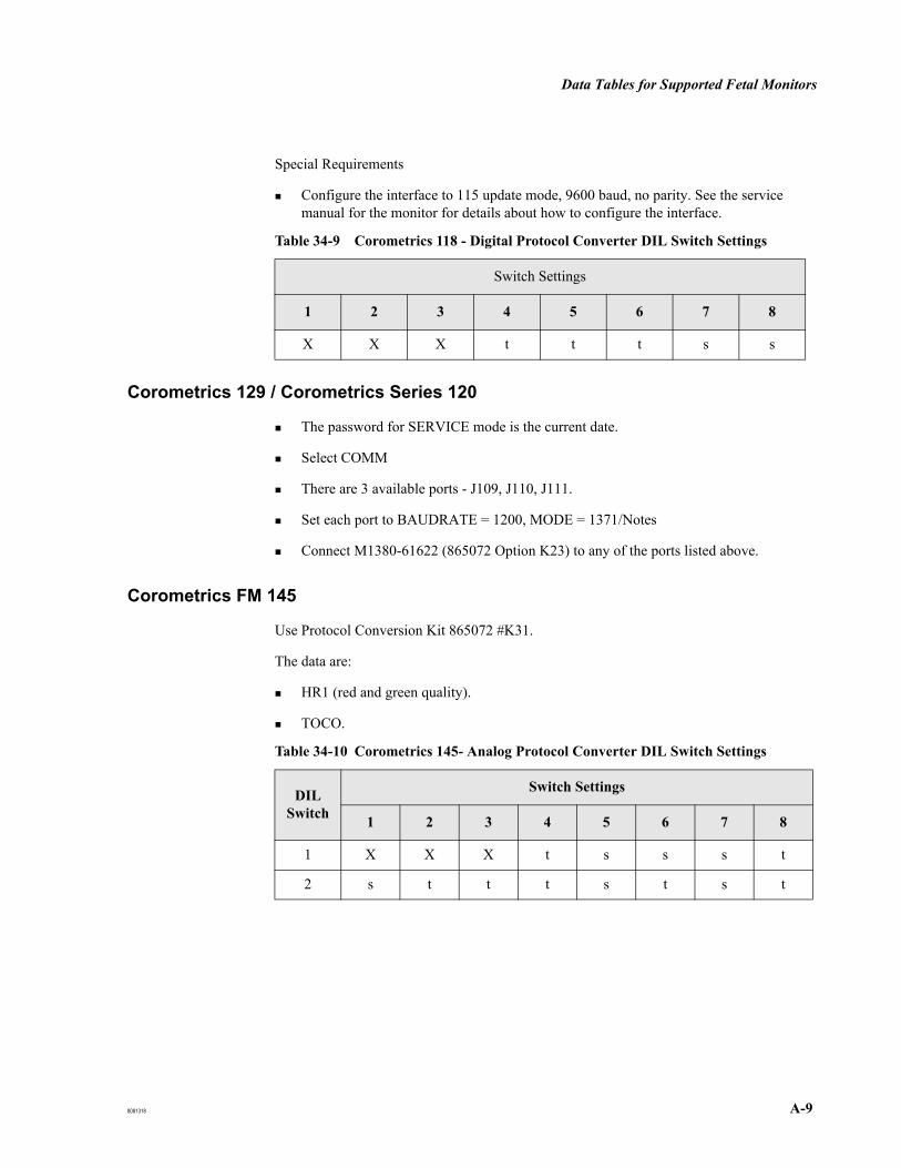
Data Tables for Supported Fetal Monitors
8081318 A-9
Special Requirements
Configure the interface to 115 update mode, 9600 baud, no parity. See the service manual for the monitor for details about how to configure the interface.
Corometrics 129 / Corometrics Series 120
The password for SERVICE mode is the current date.
Select COMM
There are 3 available ports - J109, J110, J111.
Set each port to BAUDRATE = 1200, MODE = 1371/Notes
Connect M1380-61622 (865072 Option K23) to any of the ports listed above.
Corometrics FM 145
Use Protocol Conversion Kit 865072 #K31.
The data are:
HR1 (red and green quality).
TOCO.
Table 34-9 Corometrics 118 - Digital Protocol Converter DIL Switch Settings
Switch Settings
1 2 3 4 5 6 7 8
X X X t t t s s
Table 34-10 Corometrics 145- Analog Protocol Converter DIL Switch Settings
DIL Switch
Switch Settings
1 2 3 4 5 6 7 8
1 X X X t s s s t
2 s t t t s t s t

Data Tables for Supported Fetal Monitors
A-10 8081318
Corometrics FM 112
Use Protocol Conversion Kit 865072 #K31.
The supported data are:
HR1 (red and green quality).
TOCO.
Corometrics FM 111
Use Protocol Conversion Kit 865072 #K31.
The supported data are:
HR1 (red and green quality).
TOCO.
Table 34-11 Corometrics 112 - Analog Protocol Converter DIL Switch Settings
DIL Switch
Switch Settings
1 2 3 4 5 6 7 8
1 X X X s s s t t
2 s t t t s t s t
Table 34-12 Corometrics 111 - Analog Protocol Converter DIL Switch
DIL Switch
Switch Settings
1 2 3 4 5 6 7 8
1 X X X s s s s s
2 s t t t s t s t
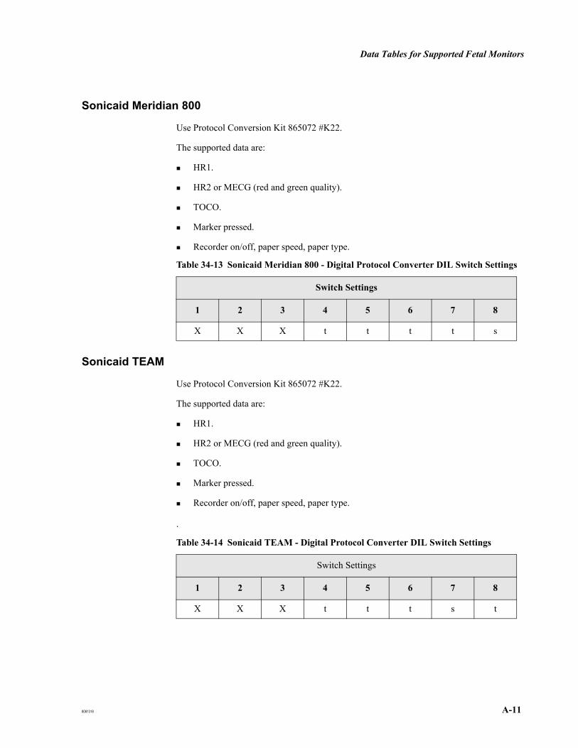
Data Tables for Supported Fetal Monitors
8081318 A-11
Sonicaid Meridian 800
Use Protocol Conversion Kit 865072 #K22.
The supported data are:
HR1.
HR2 or MECG (red and green quality).
TOCO.
Marker pressed.
Recorder on/off, paper speed, paper type.
Sonicaid TEAM
Use Protocol Conversion Kit 865072 #K22.
The supported data are:
HR1.
HR2 or MECG (red and green quality).
TOCO.
Marker pressed.
Recorder on/off, paper speed, paper type.
.
Table 34-13 Sonicaid Meridian 800 - Digital Protocol Converter DIL Switch Settings
Switch Settings
1 2 3 4 5 6 7 8
X X X t t t t s
Table 34-14 Sonicaid TEAM - Digital Protocol Converter DIL Switch Settings
Switch Settings
1 2 3 4 5 6 7 8
X X X t t t s t

Data Tables for Supported Fetal Monitors
A-12 8081318
Toitu MT332
The supported data are:
HR1 (red and green quality).
TOCO.
Special Requirements
Analog Interface required.
Locally resourced power supply.
You need to wire the following signals to the appropriate pins on the Toitu interface connector. See the Toitu manual for the pinouts for the appropriate connector:
Hr1_sig
Toc_sig
GND
See 25-pin sub D-type Connector to Protocol Converter - Analog Versions on page A-18.
Toitu MT333
The supported data are:
HR1 (red and green quality).
TOCO.
Special Requirements
Analog Interface required.
Locally resourced power supply.
You need to wire the following signals to the appropriate pins on the Toitu interface connector. See the Toitu manual for the pinouts for the appropriate connector:
Hr1_sig
Table 34-15 Toitu MT332 - Analog Protocol Converter DIL Switch Settings
DIL Switch
Switch Settings
1 2 3 4 5 6 7 8
1 X X X t t t t s
2 t t t t t t s t

Data Tables for Supported Fetal Monitors
8081318 A-13
Toc_sig
GND
See 25-pin sub D-type Connector to Protocol Converter - Analog Versions on page A-18.
Toitu MT430
The supported data are:
HR1 (red and green quality).
HR2 (red and green quality).
TOCO.
Special Requirements
Analog Interface required.
You need to wire the following signals to the appropriate pins on the Toitu interface connector. See the Toitu manual for the pinouts for the appropriate connector:
Hr1_sig
Hr2_sig
Toc_sig
+V in
GND
See 25-pin sub D-type Connector to Protocol Converter - Analog Versions on page A-18.
Note that the protocol converter can draw its power from the MT430 and therefore does not require a locally resourced power supply (unlike the other Toitu monitors mentioned above).
Table 34-16 Toitu MT333 - Analog Protocol Converter DIL Switch Settings
DIL Switch
Switch Settings
1 2 3 4 5 6 7 8
1 X X X t t t s t
2 t t t t t t s t
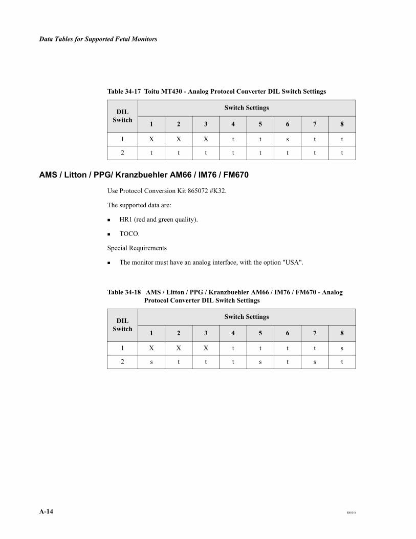
Data Tables for Supported Fetal Monitors
A-14 8081318
AMS / Litton / PPG/ Kranzbuehler AM66 / IM76 / FM670
Use Protocol Conversion Kit 865072 #K32.
The supported data are:
HR1 (red and green quality).
TOCO.
Special Requirements
The monitor must have an analog interface, with the option "USA".
Table 34-17 Toitu MT430 - Analog Protocol Converter DIL Switch Settings
DIL Switch
Switch Settings
1 2 3 4 5 6 7 8
1 X X X t t s t t
2 t t t t t t t t
Table 34-18 AMS / Litton / PPG / Kranzbuehler AM66 / IM76 / FM670 - Analog Protocol Converter DIL Switch Settings
DIL Switch
Switch Settings
1 2 3 4 5 6 7 8
1 X X X t t t t s
2 s t t t s t s t

General Purpose Kit
8081318 A-15
General Purpose KitIf you need to connect a fetal monitor that is not listed in the data tables above, you will need a general purpose kit. This provides for an analog to digital conversion, where the analog signal protocol can be sufficiently defined.
1. Consult technical marketing to check whether this type of fetal monitor has ever been successfully connected to OB TraceVue. If so, you will be provided with instructions. If not, you must take the measurements necessary to define the analog signal protocol used before instructions can be provided.
2. Modify the adapter cable specified in any or all of the following ways:
a. Locally source, and fit an appropriate connector to the adapter cable for the fetal monitor.
b. Modify the male connector to the protocol converter to accept the output from a separate, locally sourced, power supply (and isolation transformer).Refer to “Power Supply” on page A-18
c. Code the male connector of the adapter cable to the protocol converter UNIV1 (1000 - bipolar protocol) or UNIV2 (1001 - unipolar protocol).Refer to “Customizing Adapter Cables” on page A-18
3. Set up the protocol converter.
a. Set DIL switches as instructed. These depend on the definition of the fetal monitor signal protocol.Refer to “Setting Up the Converter” on page A-18
b. Load any of resistor pairs R107 and R108 (heart rate 1); R109 and R110 (heart rate 2); and R111 and R112 (TOCO) to adjust input voltage ranges, using values as instructed.
4. Validate the protocol conversion using FM Spy.Refer to “Fetal Monitor Spy (FMSpy)” on page 12-6
5. Mount the protocol converter, and connect it to OB TraceVue.

General Purpose Kit
A-16 8081318
Customizing Adapter Cables
The adapter cable in the general purpose kit cannot identify the manufacturer of the fetal monitor. However, you must customize the cable so that it has a manufacturer “identity” of either UNIV1 for bipolar analog signal or UNIV2 for an analog unipolar signal.
The identity is signified by a four character binary code. The code is formed by bridging between PINs 10 to 13 and GND (PINs 23 to 25) in the 25-pin sub D-type male connector to the protocol converter.
Coding the Identity Code a “0” by bridging the pin to GND
Code a “1” by leaving open, or snipping out, an existing bridge.
Fitting the General Purpose Protocol Conversion Kit
Power Supply Typically power is drawn from the fetal monitor. However, some monitors require a separate, locally sourced power supply that must deliver 6 to 15 VDC, 30 mA, and either conform to medical grade standards, or be powered via an isolation transformer, such as the one available in #K51.
If the PC is located at the bedside, any protocol converter (not just locally sourced) must also be connected to the isolation transformer. To connect the power feed, modify the adapter cable's 25-pin sub D-type male connector to the protocol converter: +Vin to PIN 17; GND to PINs 23, 24 or 25.
Setting Up theConverter
1. Remove the four screws on the top of the cover.
2. Remove the cover.
3. The protocol converter software is held in ROM. If this ROM is mounted in a socket, ensure the latest version of the ROM is fitted, and that the ROM is seated correctly.
4. Ensure the settings of the DIL switches inside the protocol converter are correct.
5. Replace the cover.
6. Replace the four screws in the cover.
PIN coding Identity
1000 UNIV1 (bipolar)
1001 UNIV2 (unipolar)

General Purpose Kit
8081318 A-17
Adapter Cable Pin Assignments
Table 34-19 25-pin sub-D Connector to Protocol Converter - Digital Versions
PIN Signal Name Remarks
1 2 TxD Standard RS-232 transmit 3 RxD Standard RS-232 receive 4 RTS Standard RS-232 5 CTS Standard RS-232 6 DSR Standard RS-232 7 GND Standard RS-232 8 DCD Standard RS-232 910 Code 1 Bridge to GND (PINs 23 to 25) to code 0, open to
code 1 11 Code2 Bridge to GND (PINs 23 to 25) to code 0, open to
code 1 12 Code3 Bridge to GND (PINs 23 to 25) to code 0, open to
code 1 13 Code 4 Bridge to GND (PINs 23 to 25) to code 0, open to
code 1 14 Tx + 20mA current loop transmit output 15 GND 16 Rx + 20mA current loop receive input 17 +V in +5V to +15V. Power supply for protocol converter. 18 19 20 DTR Standard RS-232 21 22 RI Standard RS-23223 GND 24 GND 25 GND

General Purpose Kit
A-18 8081318
Table 34-20 25-pin sub D-type Connector to Protocol Converter - Analog Versions
PIN Signal Name Remarks
1 PEN1 Digital CMOS active high 2 nPEN1 Digital CMOS active low 3 PEN2 Digital CMOS active high 4 nPEN2 Digital CMOS active low 5 DIG in Reserved digital CMOS input 6 GND 7 Hr1_Sig -1.2V to +2.4V analog input 8 Hr2_Sig -1.2V to +2.4V analog input 9 Toco_Sig -1.2V to +10V analog input 10 Code 1 Bridge to GND (PINs 23 to 25) to code 0, open to
code 1 11 Code2 Bridge to GND (PINs 23 to 25) to code 0, open to
code 1 12 Code3 Bridge to GND (PINs 23 to 25) to code 0, open to
code 1 13 Code 4 Bridge to GND (PINs 23 to 25) to code 0, open to
code 1 14 GND 15 1617 +V in +5V to +15V. Power supply for protocol converter. 18 19 20 Hr1_Mode -10V to +10V analog mode input 21 Hr2_Mode -10V to +10V analog mode input 22 Toco_Mode -10V to +10V analog mode input 23 GND 24 GND 25 GND
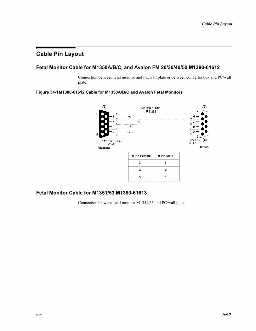
Cable Pin Layout
8081318 A-19
Cable Pin Layout
Fetal Monitor Cable for M1350A/B/C, and Avalon FM 20/30/40/50 M1380-61612
Connection between fetal monitor and PC/wall plate or between converter box and PC/wall plate.
Figure 34-1M1380-61612 Cable for M1350A/B/C and Avalon Fetal Monitors
Fetal Monitor Cable for M1351/53 M1380-61613 Connection between fetal monitor M1351/53 and PC/wall plate.
9 Pin Female 9 Pin Male
2
3
5
3
2
5
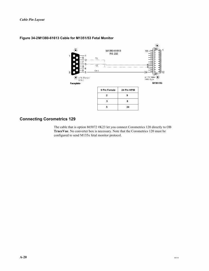
Cable Pin Layout
A-20 8081318
Figure 34-2M1380-61613 Cable for M1351/53 Fetal Monitor
Connecting Corometrics 129
The cable that is option 865072 #K23 let you connect Corometrics 120 directly to OB TraceVue. No converter box is necessary. Note that the Corometrics 120 must be configured to send M135x fetal monitor protocol.
9 Pin Female 24 Pin HPIB
2
3
5
9
8
24

Index-i
IndexAAccess rights
directories, 3-4modifying, 3-7shares, 3-5tools, 3-6
Activating the PC, 19-8active directory integration, 7-38ActiveX
real time alarming, 5-42web client, 5-42
Adapter cablepin assignments (protocol converter), 35-17protocol converter, 35-2
Additional drivers, 19-3Additional memory, 13-2Admin tool for internal database, 16-6Administrative episodes, update archive tool, 16-8ADT interface
setup, 18-5Agilent Series 50 monitors
See Series 50 monitorsAMS
protocol converter, 35-14Archive disk
care for, 10-2Auto login
interrupting, 3-7setup, 18-9
AutochangerSCSI ID, 13-12see Optical medium changers, 13-11
automatic time synchronization, 19-23Avalon fetal monitor, protocol conversion, 6-4Avalon FM connection, 6-7Avalon FM20/30 fetal monitors
connecting, 6-3
BBackup
configuration, 17-20integrating online into task scheduler, 16-14offline, 16-11, 16-12online, 16-11
Backup Tape Drive, 13-19BADFILE.TXT, 17-27Battery
replacement in client UPS, 10-1replacement in server UPS, 10-1
BIOSSettings, 19-4
Compaq Evo D510, 24-3Compaq ProLiant ML370 G2, 26-3HP Compaq D530, 25-3HP Compaq dc7100, 31-3HP Compaq dc7600, 32-3HP Compaq dc7700, 33-3HP ProLiant ML350 G4, 28-4HP ProLiant ML350 G4P, 29-3HP ProLiant ML350 G5, 30-4HP ProLiant ML370 G3, 27-3HP rp5700, 34-3
Version, 19-4Compaq Evo D510, 24-3Compaq ProLiant ML370 G2, 26-3HP Compaq D530, 25-3HP ProLiant ML350 G4, 28-4HP ProLiant ML350 G4P, 29-3HP ProLiant ML350 G5, 30-4HP ProLiant ML370 G3, 27-3
when to flash, 13-2
CC drive, see primary hard disk drive, 13-5Cabinet for optical disk drives, 13-17Cables
length limits, 6-9100Base-FX, 6-9100Base-TX, 6-9RS-232, 6-9serial port server, 6-9
CablingSpecifications, 6-9Fetal monitor, 2-17LAN, 6-10M1380-16613 fetal monitor cable for M1351/53, 35-19M1380-61612 fetal monitor cable for Avalon FM20/30, 35-19M1380-61612 fetal monitor cable for M1350A/B/C, 35-19PC, 2-17pin assignment fetal monitor cable for M1350A/B/C, 35-19pin assignment fetal monitor cable for M1351/53, 35-19safety, 2-17testing network cables, 6-9wall, 4-7
Cart mountmoving, 6-2power supplies, 6-2
Cat 5 Cable Specification, 6-9CCOW applications, 5-28CD ROM drive
installation, 13-5Centralized implementation, 2-3, 4-2certificate revocation list, 6-44Changing PC name
client, 15-1server, 15-1
Checklistinternal server installation, 5-3standalone PC installation, 5-6external server installation, 5-7WEB/Terminal server installation, 5-9client installation (data acquisition), 5-11, 5-13client installation (no data acquisition), 5-15
CIEmapping defaults, 6-49
Clientconfiguring, 5-30, 5-31connecting UPS, 5-21defining number of clients during setup, 18-5installation checklist (data acquisition), 5-11, 5-13installation checklist (no data acquisition), 5-15maximum per system, 20-3shell autostart with A.02.00, 18-9UPS, 6-2Windows new installation, 19-5
Client Setup, 19-7Cluster, of linked systems, 23-10Compaq Array Configuration Utility software, 17-41Compaq Evo D510 PC
BIOS settings, 24-3BIOS version, 24-3configuration, 24-3IDE configuration, 24-4, 25-4interrupts, 24-5lightpen settings, 24-2removing the PC cover, 24-1RS-232 card settings, 24-2SCSI BIOS, 24-5slot assignments, 24-2soundcard settings, 24-2specifications, 24-1
Compaq Insight management software, 11-9Compaq ProLiant ML370 G2 PC
BIOS settings, 26-3
Index

Index-ii
BIOS version, 26-3configuration, 26-3interrupts, 26-3RAID settings, 26-2removing the PC cover, 26-1SCSI BIOS, 26-3slot assignments, 26-1specifications, 26-1
Component Installation, 19-272nd NIC, 19-27additional RS-232, 19-30light pen, 19-30SCSI host adapter, 19-30UPS software, 19-32
Computer Management, 16-1CONFIG.TXT file, 12-1Configuration
Hardware, 19-33IDE hard disks, 19-33optical disk drives, 19-33optical medium changers, 19-34SCSI hard disks, 19-33
PCsCompaq Evo D510, 24-3Compaq ProLiant ML370 G2, 26-3HP Compaq D530, 25-3HP Compaq dc7100, 31-3HP Compaq dc7600, 32-3HP Compaq dc7700, 33-3HP ProLiant ML350 G4, 28-4HP ProLiant ML350 G4P, 29-3HP ProLiant ML350 G5, 30-4HP ProLiant ML370 G3, 27-3HP rp5700, 34-3
RSM, 13-14Serial Port Server
5210 / 5410 / 5610, 6-23DE-303 / DE-304 / DE-308, 6-21
Configuration backup, 17-20import, 17-21offline backup, 17-21online backup, 17-20reload, 17-21to optical disk (server with archiving only), 17-20, 17-21
Configuration recordCONFIG.TXT, 12-1printing, 5-34storing, 5-39
Connecting Avalon FMs to OB TraceVue, 6-7Control Panel, 16-1Conventions
caution, 1-3note, 1-3warning, 1-3
Conversion kits, 35-1Corometrics
129, 35-9FM 111, 35-10FM 112, 35-10FM 115, 35-7FM 115D, 35-7FM 116, 35-8FM 118, 35-8FM 145, 35-9
Creating a printer, 6-34CRL, 6-44Customer acceptance procedures, 2-5Customer verification, 12-1
DD530, see HP Compaq D530Data access
software engineering for 3rd party access, 5-28Data acquisition
problems, 9-6Database
admin tool for external database, 16-6admin tool for internal database, 16-6administration tools, 16-6importing data from multiple A.01.xx disks, 17-31regular maintenance, 10-1
Database rebuild tool, 16-9Database repair
archive recovery, 17-17patient file validation, 17-17validation, 17-17
dc7100, see HP Compaq dc7100dc7600, see HP Compaq dc7600dc7700, see HP Compaq dc7700DCOM service, 11-2Decentralized implementation, 2-2, 4-2Default "user" password, 3-1Defects
hardware, 14-1software media, 14-4
De-installing driver (PowerChute), 13-24DHCP
server configuration, 19-9, 19-17dip switch settings, Plasmon drive, 13-10, 13-13Directory paths, HA sysstem, 7-1Disk copy
optical disk test tool, 17-25Display
connecting, 5-18specifications, 4-5
DMI support, 11-9Documentation, 4-11domain integration, 7-38Double charting, 17-19Drive letters, 19-22
EEarth Terminal symbol, 2-1Electrostatic handling precautions, 2-18EMC Autostart
domain integration, 7-6domain integration of HA server, 7-38domain monitoring, 7-23health status icon, 7-39installation record, 7-6installing, 7-2lock computer, 7-17Management Console, 7-17manual failover, 7-23OB TraceVue software upgrade, 7-20, 7-21offline backup creation, 7-24offline backup restoration, 7-24passive server maintenance, 7-23server recovery, 7-26, 7-29shutting down OB TraceVue, 7-19stalled server synchronization, 7-31starting OB TraceVue, 7-19status display refresh, 7-39timeserver, 7-10upgrade from existing database, 7-4
Emergency boot floppy disksee boot disk

Index-iii
Equipotential Terminal symbol, 2-1Error log files
recommended maintenance, 10-1Error messages
RFA, 17-39Event viewer, 16-1Evo D510, see Compaq Evo D510External database
backup, 13-19defining at setup, 18-6
External database admin tool, 16-3External database server
backup device, 13-19installation checklist, 5-7Windows new installation, 19-5
External Database Server Setup, 19-6External server
USB backup device, 19-34External time server, 19-23
FFaceplates, 4-7Fast user switching, 19-18Fax
setting up, 6-39fetal monitor
cabling, 2-17Fetal monitors
cable for M1350A/B/C, 35-19cable for M1351/53, 35-19connecting, 5-23, 6-3connecting four monitors, 6-4connection, 19-25, 35-1connection problems, 9-6conversion kits, 35-1data tables for types supported, 35-5disconnecting from PC, 35-4general purpose conversion kit, 35-15HP 8040A, 35-5M1350A, 6-6M1350B, 6-6M1351/53, 6-5protocol converter kits, 35-2signal protocols, 19-25, 35-1system limitations, 4-8types supported, 35-2
FileLog files, 11-7BADFILE.TXT, 17-27BADPAT.TXT, 17-28CONFIG.TXT, 12-1DISKTOOL.LOG, 17-25GOODFILE.TXT, 17-27GOODPAT.TXT, 17-28MISSING.TXT, 17-27RFAWIZ.TXT, 17-38UNREFERENCED.TXT, 17-27
File system checkoptical disk test tool, 17-26
Firewall, System Overview tool configuration, 11-2Flashing
BIOS, 13-2Floppy disk drive
disabling, 5-35unlocking/locking, 13-1
FM670protocol converter, 35-14
FMSpy, 16-23closing, 16-23digital interpretation, 16-24monitor data, 16-24port initialization, 16-24
starting, 16-23using, 16-23
Functionality test, 5-32
GGetLog, 16-27
HHA system directory paths, 7-1Hard disk
IDE, 13-7secondary hard disk, 13-7
Hardwarecomponents, 4-4defects, 14-1installing, 3-1, 6-1PC specifications, 4-4problems, 9-5replacement parts, 14-1
High availabilityCo-StandbyServer AAdvanced, 7-1hardware upgrade, 7-2installing EMC Autostart, 7-2management console, 7-1
HIS, 4-1HIS-ID domain, 23-13HL7
inbound mapping, 6-49mapping defaults, 6-49outbound mapping, 6-49setting up, 5-29
Hospital Information System, see HISHost adapter
SCSI, 13-6HP 8040A protocol converter, 35-5HP Array Configuration Utility software, 17-41HP Compaq D530 PC
BIOS settings, 25-3BIOS version, 25-3configuration, 25-3interrupts, 25-5lightpen settings, 25-2removing the PC cover, 25-1RS-232 card settings, 25-2SCSI BIOS, 25-5slot assignments, 25-2soundcard settings, 25-2specifications, 25-1
HP Compaq dc7100 PCBIOS settings, 31-3configuration, 31-3removing the PC cover, 31-1specifications, 31-1
HP Compaq dc7600 PCBIOS settings, 32-3configuration, 32-3removing the PC cover, 32-1specifications, 32-1
HP Compaq dc7700 PCBIOS settings, 33-3configuration, 33-3removing the PC cover, 33-1specifications, 33-1
HP Insight management software, 11-9HP Optical Drive Settings, 13-9HP ProCurve Switch 2312, 6-8HP ProCurve Switch 2324, 6-8HP ProLiant ML350 G4
SCSI BIOS, 28-5HP ProLiant ML350 G4 PC
BIOS settings, 28-4BIOS version, 28-4

Index-iv
configuration, 28-4interrupts, 28-5, 29-4RAID settings, 28-2, 29-2removing the PC cover, 28-1slot assignments, 28-1specifications, 28-1
HP ProLiant ML350 G4PSCSI BIOS, 29-4
HP ProLiant ML350 G4P PCBIOS settings, 29-3BIOS version, 29-3configuration, 29-3removing the PC cover, 29-1slot assignments, 29-1specifications, 29-1
HP ProLiant ML350 G5SCSI BIOS, 30-6
HP ProLiant ML350 G5 PCBIOS settings, 30-4BIOS version, 30-4configuration, 30-4interrupts, 30-6RAID settings, 30-2removing the PC cover, 30-1slot assignments, 30-1specifications, 30-1
HP ProLiant ML370 G3 PCBIOS settings, 27-3BIOS version, 27-3configuration, 27-3interrupts, 27-3RAID settings, 27-2removing the PC cover, 27-1SCSI BIOS, 27-3slot assignments, 27-1specifications, 27-1
HP rp5700 PCBIOS settings, 34-3removing the PC cover, 34-1specifications, 34-1
HP rp700 PCconfiguration, 34-3
HP Series 50 monitorsSee Series 50 monitors
IIDE configuration
Compaq Evo D510, 24-4, 25-4HP Compaq dc7100, 31-4HP Compaq dc7600, 32-5
IDE hard disk, 13-7IM76
protocol converter, 35-14Incoming connection, 6-41Input Locale, 19-25inspection matrix, see Test and Inspection matrixinstall.txt, see also Installation Record, 16-23Installation
check shipment, 5-17client UPS, 5-21connect 2nd network card, 5-24connect modem, 5-24, 5-27connect to network, 5-24display, 5-18external server UPS, 5-21fetal monitors, 5-23functionality test, 5-32isolation transformer, 5-22
keyboard and mouse, 5-18light pen, 19-30OB TraceVue software, 18-4optical disk drive cabinet, 5-18Optical medium changers, 13-11power switch cover, 5-39put equipment in place, 5-17remote client, 6-11retrieve drive, 5-19safety tests, 5-33serial port server software (5210 / 5410 / 5610), 6-19serial port server software (DE-303 / DE-304 / DE-308), 6-19server UPS, 5-21set timezone and local time, 5-27, 5-28set up OB TraceVue to work with CCOW applications, 5-28set up soundcard, 5-27software engineering for 3rd party data access, 5-28storage drive, 5-19switch on PC, 5-26touchscreen driver, 5-26UPS, 5-21virus protection software, 10-3voltage selection switch, 5-17warning label, 5-39Web terminal server UPS, 5-21
Installation checklistinternal server, 5-3standalone PC, 5-6external server, 5-7WEB/Terminal server, 5-9client (data acquisition), 5-11high-end (data acquisition), 5-13client (no data acquisition), 5-15
Installation recordinstall.txt, 16-23printing, 5-34
Interfaces, 4-10interfacing
additional network interface, 4-10ADT and ORU, 4-10ADT only, 4-10HL7 interface, 4-10
Internal database admin tool, 16-6functionality, 16-6, 16-7, 16-9when to use, 16-3
Internal serverC drive, 13-5CD-ROM drive, 13-5configuring, 5-29connecting UPS, 5-21how to change PC name, 15-1installation checklist, 5-3SCSI host adapter, 13-6Windows new installation, 19-5
International Caution symbol, 2-1Interrupting Auto Login, 3-7Interrupts
Compaq Evo D510, 24-5, 25-5Compaq ProLiant ML370 G2, 26-3HP ProLiant ML350 G4, 28-5, 29-4HP ProLiant ML350 G5, 30-6HP ProLiant ML370 G3, 27-3
IP AddressDHCP server, 19-17second NIC, 19-28serial port server, 6-17serial port server host PC, 6-15
Isolation transformer, 4-8

Index-v
connecting, 5-22connecting to UPS, 5-22safety when connecting a PC, 2-17with UPS in patient vicinity, 2-4
JJetDirect card
using, 6-37Jukebox
see Optical medium changers, 13-11
KKeyboard
connecting, 5-18Kranzbuehler AM66
protocol converter, 35-14
LLAN
see networkLAN card, see Network I/F card, 13-3Language
define system language (OB TraceVue setup), 18-8License
balancing (WEB/Terminal server), 5-36OB TraceVue, 23-4storing, 5-39Windows, 23-4
Lightpen, 19-30settings for Compaq Evo D510, 24-2settings for HP Compaq D530, 25-2
LimitationsRFA tool, 17-30
Limitations, see System LimitationsLink
see OBTV to OBTV linkLink recovery tool, 17-18
log files, 17-19using, 17-19
Linking systems, 23-6, 23-17direct link, 23-17merge and link, 23-18
Littonprotocol converter, 35-14
Local Data Recovery tool, 17-15recovery process, 17-16using, 17-15
Locale, 19-25Log files, 11-7
available logs, 16-22GetLog, 16-27link recovery tool, 17-19local data recovery tool, 17-15optical disk test tool, 17-25path, 16-22RFA, 17-38tool to collect all available log files (GetLog), 16-27
LogFile Viewer, 16-17starting, 16-17using, 16-17
MM1350A, 6-6
cable pin assignment, 35-19M1350B, 6-6
cable pin assignment, 35-19M1350C
cable pin assignment, 35-19M1351
cable pin assignment, 35-19M1351/53 fetal monitor, 6-5M1353
cable pin assignment, 35-19M1380-16612
fetal monitor cable for M1350A/B/C pin assignment, 35-19M1380-16613
fetal monitor cable for M1351/53 pin assignment, 35-19M1380-60501, 13-3M1380-66501, 13-3Maintenance
checking the internal database, 10-1client UPS, 10-1error log files, 10-1optical disk drive, 10-1optical disks, 10-1recommended, 10-1
Management SoftwareHP / Compaq Insight Manager, 11-9
Manualorganization, 1-1readership, 1-1
Manual failover, performing, 7-23mapping defaults, 6-49Maximum clients per system, 20-3Memory
additional, 13-2requirements, 20-3
Web/Terminal server, 20-7, 20-8Merging systems, 23-6, 23-14
multiple admissions, 23-8RFA report, 23-15
Merging/linking systemsarchive update, 23-12configuring unique system names, 23-12HIS-ID domain, 23-13link recovery reports, 23-9link recovery tool, 23-10patient identification, 23-7
Mergingl/linking systemsprerequisites, 23-10
MicrosoftExcel
template installation, 6-46updating templates (prior to B.00.00), 21-12upgrading templates, 21-10
Wordtemplate installation, 6-46upgrading templates, 21-10
Microsoft Vista, 5-40MO drive, standalone
operating plane, 20-2Mobile client
shutting down, 6-2Modem
connecting, 5-24, 5-27incoming connection, 6-41installing (Windows administrator), 6-40outgoing connection, 6-40system limitations, 4-9
Mouseconnecting, 5-18
NNetwork
specifications, 6-8cable specifications, 6-9cable testing, 6-9cabling a LAN, 6-10connecting, 5-24, 6-8connecting 2nd network card, 5-24connecting a PC to a switch, 6-10connecting the PC to the LAN cable, 6-10errors, 9-3examples with 2 switches, 6-10

Index-vi
installing a printer, 6-37printing, 6-37problems, 9-3security, 5-33serial port server settings, 6-17supported switches, 6-8system description, 4-10wall cable types, 6-9with switch, 6-8
Network based storage, troubleshooting, 9-4Network I/F card
installing, 13-3Network verification, 2-17NIC
second, 19-27NIC assignment, 19-27
OOB TraceVue
configuring at client PCs, 5-32Configuring at Internal Server PC, 5-32definition, 1-1documentation, 4-11installing the software, 18-4license updates, 23-4reinstalling, 18-1starting, 5-31tools, 16-6uninstalling, 18-12
OB TraceVue CD ROM, 19-1OB TraceVue Setup, 18-2OB TraceVue shell
installing at setup, 18-9OBTV to OBTV link, 18-5
uninstalling, 18-13Office 2007, 6-42Offline backup tool, 16-4Optical disk
care, 10-2care for archive disk, 10-2care for retrieve disk, 10-2cleaning kit, 10-3recommended maintenance, 10-1test tool, 17-23
Optical disk drive, 13-9cabinet, 13-17care, 10-2connecting archive drive, 5-19connecting retrieve drive, 5-19installing a retrieve drive, 23-3SCSI ID, 19-33supported drive combinations, 4-5
Optical disk drive cabinet, 13-17installing, 5-18
Optical disk recovery process, 17-24Optical disk test tool, 17-23
archive file check, 17-27BADFILE.TXT, 17-27BADPAT.TXT, 17-28checking patient data, 17-28disk copy, 17-25error log, 17-25file system check, 17-26GOODFILE.TXT, 17-27GOODPAT.TXT, 17-28log file, 17-25low level check, 17-25MISSING.TXT, 17-27
progress and status, 17-25recovery process, 17-24requirements, 17-23UNREFERENCED.TXT, 17-27using, 17-24
Optical Drive SettingsHP, 13-9Plasmon, 13-9
Optical drivesSCSI cable lengths, 13-10
Optical medium changer, 13-11Installation, 13-11SCSI cable lengths, 13-13SCSI ID, 19-34Windows device driver installation, 19-31
Outgoing connection, 6-40overview of all PCs, 11-2
PParallel printing, 6-33, 6-36Parts, 14-5
hardware, 14-4how to obtain replacement parts, 14-5software media, 14-4
Passwordfor change system options during setup, 18-5
Password security, 3-1Patient safety, 2-1PC
activation, 19-8cabling, 2-17Compaq Evo D510, 24-1Compaq ProLiant ML370 G2, 26-1HP Compaq D530, 25-1HP Compaq dc7100, 31-1HP Compaq dc7600, 32-1HP Compaq dc7700, 33-1HP ProLiant ML350 G4, 28-1HP ProLiant ML350 G4P, 29-1HP ProLiant ML350 G5, 30-1HP ProLiant ML370 G3, 27-1HP rp5700, 34-1power consumption, 2-4specifications, 4-4supported PCs, 20-2
PC Management SoftwareHP / Compaq Insight, 11-9
PC Name, 15-1how to rename a client PC, 15-1how to rename a server PC, 15-1
PC serial number, 15-1PC system board
replacement, 13-2PCI RS-232 card
see RS-232 cardPerformance monitor, 16-2Performance tests
RS-232, 2-9RS232, 2-9software, 2-7UPS, 2-9
Philips Series 50 monitorsSee Series 50 monitors
Plasmon Optical Drive Settings, 13-9Port server
see Serial port serverPort settings
defining at setup, 18-6

Index-vii
Power consumption, 2-4Power supply
protocol converter, 35-16Power switch cover, 5-39PowerChute
de-installing, 13-24PPG
protocol converter, 35-14Primary hard disk drive
installation, 13-5Printer, 6-33
creating, 6-34creating a network printer, 6-37installing a network printer, 6-37network port, 6-37parallel port, 6-36protocol settings, 6-37using an HP JetDirect Card, 6-37
Printer Configuration Menu, 6-37Printing
configuration record, 5-34installation record, 5-34
ProLiant G2see Compaq ProLiant ML370 G2
ProLiant G3see HP ProLiant ML370 G3
ProLiant G4see HP ProLiant ML350 G4see HP ProLiant ML350 G4P
Protocol conversionoverview, 6-4converter box, 35-1kit description, 35-1
Protocol converteradapter cable, 35-2AMS, 35-14Corometrics FM 111, 35-10Corometrics FM 112, 35-10Corometrics FM 115, 35-7Corometrics FM 115D, 35-7Corometrics FM 116, 35-8Corometrics FM 118, 35-8Corometrics FM 145, 35-9customizing adapter cables, 35-16DIL switches, 35-5, 35-6disconnecting, 35-4fitting, 35-16FM670, 35-14general purpose kit, 35-15HP 8040A, 35-5IM76, 35-14kits available, 35-2Kranzbuehler AM66, 35-14Litton, 35-14mounting, 6-4, 35-3power supply, 35-16PPG, 35-14Sonicaid Meridian 800, 35-11Sonicaid TEAM, 35-11Toitu MT332, 35-12Toitu MT333, 35-12Toitu MT430, 35-13
RRAID
configurationCompaq ProLiant ML370 G2, 26-2HP ProLiant ML350 G4, 28-2, 29-2HP ProLiant ML350 G5, 30-2HP ProLiant ML370 G3, 27-2
HP / Compaq Array Configuration Utility, 17-41Rebuild tool
external database, 16-9internal database, 16-9
Recommended maintenance, see maintenanceRecovery, 17-8, 17-11, 17-13
client, 17-14database recovery, 17-15external database server, 17-13internal server with archiving, 17-8linked systems, 17-18local data recovery tool, 17-15optical disk test tool, 17-23optical disks, 17-24server with archiving, 17-8server with RAID array, 17-4server without archiving, 17-11Web terminal server, 17-13
Recovery process, 17-4recovering client’s hard disk, 17-14recovering external server’s hard disk, 17-13recovering server’s backup (secondary) hard disk, 17-9reinstalling the server, 17-11, 17-13
registry mirror, 7-12Reinstalling
OB TraceVue, 18-1server (recovery process), 17-11, 17-13
RemoteFax, 6-39Support, 6-38Trace transmission, 6-38Web access, 6-38
Remote Clientconfigure IP address of server, 18-9installing and configuring, 6-11
Remote connectivity, 6-38Remote Desktop, 11-3Remote LAN Client
limitations, 6-11prerequisites for installing and configuring, 6-11
Remote Support, 11-3Remote support, 11-3
enabling, 11-4modem setup, 11-4terminal services client installation, 11-5using terminal services client, 11-6
Removable Storage Manager (RSM), 13-14Renaming
client PC, 15-1server PC, 15-1
Repair, 14-1Optical Medium Changers, 14-2
Replaceable parts, see Parts, 14-4Retrieve
connecting drive, 5-19Retrieve disk
care for, 10-2RFA tool, 17-29
checks before running, 17-31error messages, 17-39importing A.01.64 data, 17-35limitations, 17-30log file, 17-38merging archive index, 17-35requirements, 17-29rimporting A.02.10 or higher data, 17-34using, 17-33
RS-232cable specifications, 6-9M1380-66501, 13-3manual driver installation, 13-3serial port server connectors, 6-9, 6-26settings for Compaq Evo D510, 24-2settings for HP Compaq D530, 25-2

Index-viii
testing ports using FMSpy, 13-4RSM, 13-14RSM configuration, 13-14
SSafety
cabling, 2-17electrostatic handling precautions, 2-18installation, 2-17symbols, 2-1
Safety tests, 2-5, 5-33enclosure leakage current/normal condition, 2-10enclosure leakage current/single fault condition, 2-10PC in patient vicinity, 2-10PC not in patient vicinity, 2-10performance RS-232, 2-9performance RS232, 2-9performance serial port server, 2-9performance software, 2-7performance tests, 2-6power on test, 2-6procedures, 2-11protective earth, 2-16site preparation, 2-17UPS, 2-9visual inspection, 2-6when to perform, 2-16
SATA configurationHP Compaq dc7100, 31-4HP Compaq dc7600, 32-4HP Compaq dc7700, 33-4HP rp5700, 34-4
SCSIaddress
archive drive, 19-33retrieve drive, 19-33medium changers, 19-34
BIOSloading, 19-4Compaq Evo D510, 24-5Compaq ProLiant ML370 G2, 26-3HP Compaq D530, 25-5HP Proliant ML350, 28-5HP Proliant ML350 G4P, 29-4HP Proliant ML350 G5, 30-6HP ProLiant ML370 G3, 27-3
cable lengthsoptical drives, 13-10optical medium changers, 13-13
host adapterM1381-66404, 13-6
SCSI ID, autochanger, 13-12Second network interface card, 19-27Second NIC, 19-27Secondary hard disk
Compaq Evo D510, 13-7HP Vectra VL 400, 13-7HP Vectra VL 420, 13-7IDE disk, 13-7recovery after failure, 17-9replacing, 13-7upgrade installation, 13-7
Security, 3-1Windows, 3-2
securityWEB/Terminal Server enhancements, 19-20
Send Note, 16-26Serial port server, 6-13
configuration, 6-21connecting, 6-16device driver, 6-19example installation, 6-13host PC, 6-15installation, 6-14installation documentation
host PC, 6-31port server, 6-29
network settings, 6-17OB TraceVue configuration, 6-26replacing, 6-27
Serial Port Server 5610, 6-23serial port server firmware upgrade, 20-9Series 120, 35-9Series 50 monitors, 6-3Server
See internal server, 5-3Server Recovery
EMC Autostart, 7-29Server/Standalone Setup, 19-6Service pack
OB TraceVue, 1-2session name
WEB/Terminal server, 19-20Settings
HP Optical Drive, 13-9Plasmon Optical Drive, 13-9
Setupadvanced alarming, 18-5advanced alerting, 18-5auto login, 18-9basic alarming, 18-5basic alerting, 18-5change options screen, 18-5change PC options, 18-5configure IP addresses of servers for Remote Clients, 18-9define alarm sounds, 18-8define alarm symbols, 18-8define system language, 18-8drive settings, 18-6external database, 18-6external interface settings (for HL7), 18-8finish, 18-10found system screen, 18-3HL7 detailed configuration, 18-8HL7 interface, 18-5installing OB TraceVue shell, 18-9number of clients, 18-5OB Tracevue software, 18-2, 18-3OBTV to OBTV link, 18-5password for change options, 18-5port screen, 18-7port settings, 18-6remote support modem, 11-4screens, 18-3starting OB TraceVue software setup, 18-2, 18-3storage options, 18-5welcome screen, 18-3
Setup failure during upgrade, 21-7Shell
installing OB TraceVue shell, 18-10Shipment status, 4-3Single HIS-ID domain, 23-13Slot assignment
Compaq Evo D510, 24-2Compaq ProLiant ML370 G2, 26-1HP Compaq D530, 25-2

Index-ix
HP ProLiant ML350 G4, 28-1HP ProLiant ML350 G4P, 29-1HP ProLiant ML350 G5, 30-1HP ProLiant ML370 G3, 27-1
SNMP, 5-33Software
components, 4-6media defects, 14-4reinstalling OB TraceVue, 18-1replacing the Windows operating system media, 14-4third party software, 4-6
Software upgrade, 21-1Software upgrades
templates, 21-10Sonicaid Meridian 800
protocol converter, 35-11Sonicaid TEAM
protocol converter, 35-11Soundcard
setting up, 5-27settings for Compaq Evo D510, 24-2settings for HP Compaq D530, 25-2
Spare PCserver with RAID, 17-5
Special tools, 1-2Specification
Network switch, 6-8Specifications, 34-1
Cables100Base-FX, 6-9CAT-5, 6-9RS-232, 6-9
Display (monitor), 4-5Memory requirements
Web/Terminal server, 20-7, 20-8Modems, 4-9
number of modems per PC, 4-9number of modems per system, 4-5, 4-9
Number of clientsWeb/Terminal server, 20-7, 20-8
PCssupported PCs, 20-2Compaq Evo D510, 24-1Compaq ProLiant ML370 G2, 26-1HP Compaq D530, 25-1HP Compaq dc7100, 31-1HP Compaq dc7600, 32-1HP Compaq dc7700, 33-1HP ProLiant ML350 G4, 28-1HP ProLiant ML350 G4P, 29-1HP ProLiant ML350 G5, 30-1HP ProLiant ML370 G3, 27-1HP rp5700, 34-1
Serial port server connectors, 6-26SPS
see Serial port serverstandalone MO drive
operating plane, 20-2Standalone PC
installation checklist, 5-6Windows new installation, 19-5
Stockingparts, 14-5
Storageconnecting drive, 5-19setup, 18-5
Supported PCs, 20-2Switch
12 port, 6-824 port, 6-8connecting a PC to a, 6-10supported with OB TraceVue, 6-8
Sybase Central, 16-2Symbols
earth terminal, 2-1equipotential terminal, 2-1international caution symbol, 2-1safety, 2-1
System description, 1-1, 4-1System limitations
fetal monitors, 4-8modem, 4-9power, 4-8
System linkage, 23-6System merge, 23-6System overview, 2-2
centralized system, 2-3decentralized system, 2-2
system overview toolrebooting a client PC, 11-2rebooting a system, 11-2starting a client, 11-2starting a system, 11-2stopping a client, 11-2stopping a system, 11-2
System upgrade, 7-1, 23-1
TTape Drive, 13-19
installation, 13-20preparing, 5-35required components, 13-20
Task scheduler, integrating online backup, 16-14Telemetry, 6-1Templates
directory structure, 6-46new installation, 6-48prerequisites, 21-10revisions, 6-47updating Excel templates (prior to B.00.00), 21-12
Terminal ServicesSee Remote Desktop, 11-3
Terminal servicesclient, 11-5remote support, 11-3, 11-4
Test and inspection matrix, 2-6Third party software, 4-6timer server PC, 19-23Toco
FMSpy, 16-25Toitu MT332
protocol converter, 35-12Toitu MT333
protocol converter, 35-12Toitu MT430
protocol converter, 35-13token repair methods, repairing patient tokens, 17-32Tools
Computer Management, 16-1database rebuild tool, 16-9Device manager, 16-1FMSpy, 16-23GetLog, 16-27installation record (install.txt), 16-23internal database admin tool, 16-6LogFile Viewer, 16-17OB TraceVue tools, 16-6offline backup, 16-4RFA, restoring the external database, 17-37RFA, restoring transfer states, 17-36RFA, retrieving data, 17-35Windows Control Panel, 16-1Windows disk management, 16-1Windows event viewer, 16-1

Index-x
Windows licensing, 16-1Windows performance monitor, 16-2Windows Services, 16-1Windows standard tools, 16-1
Touchscreendriver, 5-26
Troubleshooting, 9-1application, 9-7data acquisition, 9-6fetal monitor connections, 9-6hardware, 9-5network, 9-1network based storage, 9-4storage, 9-7system setup, 9-1
UUninstall
OB TraceVue, 18-12OBTV link, 18-13
Upgradehardware, 22-1
from A.02.10 or higher, 22-2software, 21-1System
adding WEB client licenses, 23-5adding WEB/Terminal server PC, 23-5to archiving system, 23-2to archiving system (medium changer), 23-2to larger network, 23-4using optical disk drives, 4-5
upgradeserial port server firmware, 20-9
UPS, 13-22battery replacement, 10-1client, 6-2connected to isolation transformer, 2-4connecting at the client, 5-21connecting at the server, 5-21in patient vicinity, 2-4performance tests, 2-9software
disabling, 13-24installing, 19-32simple solution, 13-24smart solution, 13-22
USB backup device for external server, 19-34User configuration record, see Configuration recorduser defined WEB/Terminal server session name, 19-20User password, default, 3-1
VVerification
CONFIG.TXT file, 12-1customer, 12-1
Virus protection, 10-3Vista, Microsoft, 5-40Voltage selection switch, 5-17
WWall cabling, 4-7, 6-9Warning label, 5-39WEB access (modem), 6-38
setting up WEB client, 6-38setting up WEB/Terminal server, 6-38
WEB clientstarting, 6-38
WEB TS client with Vista, 5-40WEB/Terminal Server
adding, 23-5adding client licenses, 23-5Configuration, 19-14configuration change, 19-20enhancing security, 19-20installation checklist, 5-9memory requirements, 20-7, 20-8number of WEB clients, 20-7, 20-8rebooting, 10-3recovery, 17-13user defined session name, 19-20Windows new installation, 19-5
WEB/Terminal Server Setup, 19-6Windows
access rights, 3-4configuration, 19-9
client, 19-16DHCP server, 19-17drive letters, 19-22external database server, 19-12, 19-15external database server for HA systems, 19-13HA server, 19-11Regional settings, 19-25server/standalone, 19-9Time service, 19-23Time zone, 19-22WEB/Terminal server, 19-14
Device Manager, 16-1Device manager, 16-1Disk Management, 16-1Event viewer, 16-1license update, 23-4new installation, 19-5performance monitor, 16-2pre-installation checks, 19-3preliminary work (before installing), 19-3security, 3-2Services, 16-1users, 3-2when to install, 19-2