philadelphia community college - center for business & industry
TRANSCRIPT

Philadelphia Community College - Center for Business & Industry 18th & Callowhill Streets - Philadelphia, PA Bernie Dougherty Penn State AE Senior Thesis Structural Option
AE 482A - Spring 2004 Consultant – Geschwinder
Final Report
1
Table of Contents
Executive Summary - Comparing Alternate Structural Systems 3
Introduction 5
Primary Project Team 8
Loads 8
Alternative Structural Systems: A General Overview 12
Live Load Reduction 17
Composite Steel Joist System
Composite Steel Bar Joist System Design 18
Composite Steel Bar Joist System Overview 19
Steel Layout 22
Gravity System Design 26
Mechanical System Changes 27
Lateral System Design 29
Foundation System Design 31
Base Plate Design 32

Philadelphia Community College - Center for Business & Industry 18th & Callowhill Streets - Philadelphia, PA Bernie Dougherty Penn State AE Senior Thesis Structural Option
AE 482A - Spring 2004 Consultant – Geschwinder
Final Report
2
Vibration and Deflection 33
Fire Protection 34
Acoustics 35
Bridging Requirements 36
Architectural Modifications 37
Advantages of Steel Joist Design 39
Disadvantages of Steel Joist Design 41
Conclusions
General Conclusions 44
Conclusions: Overall Comparison of Structural Systems 46
Acknowledgements 47
Bibliography 48

Philadelphia Community College - Center for Business & Industry 18th & Callowhill Streets - Philadelphia, PA Bernie Dougherty Penn State AE Senior Thesis Structural Option
AE 482A - Spring 2004 Consultant – Geschwinder
Final Report
3
Executive Summary
Comparing Alternate Structural Systems
The Philadelphia Community College’s Center for Business & Industry is a five
level, mixed use facility located in downtown Philadelphia, PA. The building is nearly
rectangular in shape and consists of three stories of classrooms and administrative space
over a two story parking garage. The decision of choosing the optimal building structural
system was a large consideration in the development of this construction project.
While some buildings may only have few practical options for their structural
systems, the relatively simple layout of this particular building along with its low height
suggest many different framing options. This thesis compares the original composite steel
framing system to the proposed composite steel joist system. The advantages and
disadvantages of each system will be thoroughly examined in later sections. By looking in
depth at the strength parameters of the proposed system design as well as serviceability,
economic, scheduling and architectural concerns, it will be possible to develop a more
insightful decision for the project’s optimal structural system. The following details the
research, design, and analysis of the proposed structural system and its implications on cost
and scheduling concerns.

Philadelphia Community College - Center for Business & Industry 18th & Callowhill Streets - Philadelphia, PA Bernie Dougherty Penn State AE Senior Thesis Structural Option
AE 482A - Spring 2004 Consultant – Geschwinder
Final Report
4
As noted earlier, the Center for Business & Industry was built using composite steel
construction as its framing system. After evaluation, it was determined that the next most
practical alternate framing system for this particular building was a steel joist system,
preferably taking advantage of composite action when necessary. The depth of this
research involves the design and evaluation of this alternate system and the breadth of this
study examines the scheduling and cost estimation of this alternate system. Fire ratings,
acoustical effects, vibration, and overall constructability were also studied in some detail
and incorporated into this report. This comparison between these two framing systems
shows that the original composite steel system has several desirable features that, in
comparison to the alternate system, outweigh the benefits of the proposed composite joist
system.
Philadelphia Community College - Center for Business & Industry 18th & Callowhill Streets - Philadelphia, PA Bernie Dougherty Penn State AE Senior Thesis Structural Option
AE 482A - Spring 2004 Consultant – Geschwinder
Final Report
5
Introduction
Philadelphia Community College - Center for Business & Industry 18th & Callowhill Streets - Philadelphia, PA Bernie Dougherty Penn State AE Senior Thesis Structural Option
AE 482A - Spring 2004 Consultant – Geschwinder
Final Report
6
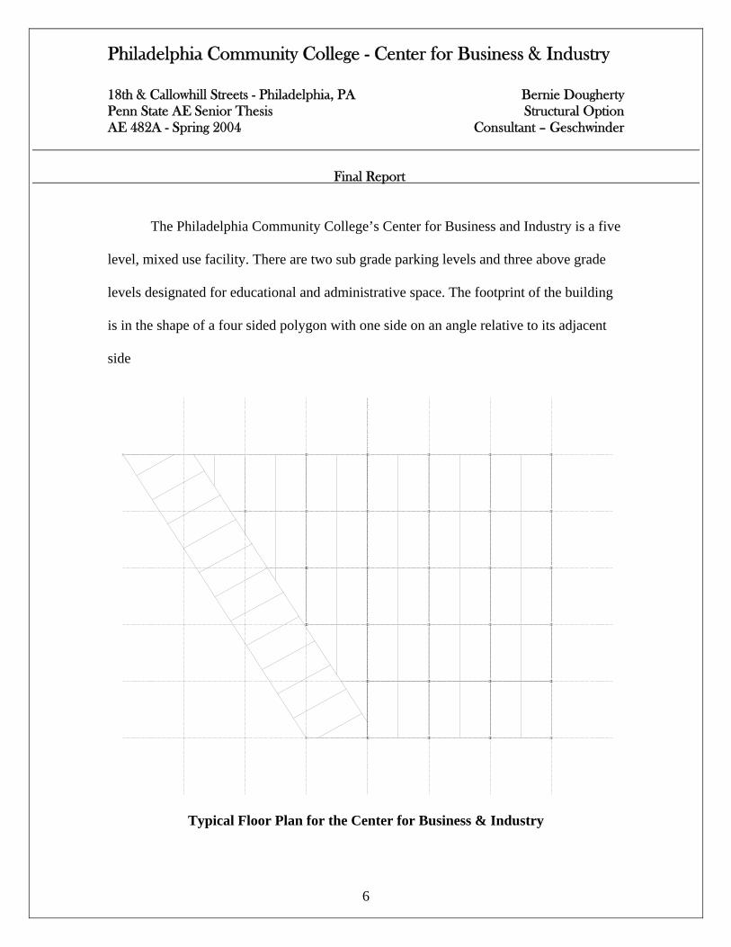
The Philadelphia Community College’s Center for Business and Industry is a five
level, mixed use facility. There are two sub grade parking levels and three above grade
levels designated for educational and administrative space. The footprint of the building
is in the shape of a four sided polygon with one side on an angle relative to its adjacent
side
Typical Floor Plan for the Center for Business & Industry
Philadelphia Community College - Center for Business & Industry 18th & Callowhill Streets - Philadelphia, PA Bernie Dougherty Penn State AE Senior Thesis Structural Option
AE 482A - Spring 2004 Consultant – Geschwinder
Final Report
7
The dimensions of the building footprint are approximately 180 ft by 240 ft. The
building houses a new cyber café, a two story atrium, classroom space and office space
for administrative personnel. The project is located in downtown Philadelphia, PA and
will cater to the needs of the community in an expanding college campus downtown. The
approximate cost for the building was 19 million dollars including land acquisition,
development and construction.
The project was constructed using a very efficient framing type. The building
features a composite steel system with composite metal deck. Lateral reinforcement is
provided by some moment frames in the short direction established by the full depth
connections welded at all girder to column connections. The original depth of the slab is
6 inches with three of these six inches of concrete being used in compression for the
design of the beams. Concrete strength was specified to be 4000 psi. Floor to floor
heights are 12 ft below grade and 14ft above grade. With the exception of the sloping
wall, the column grid is fairly regular. Typical beam and girder spans range from 30 to 40
feet and initial site work began in August 2001 and concluded in January, 2002.

Philadelphia Community College - Center for Business & Industry 18th & Callowhill Streets - Philadelphia, PA Bernie Dougherty Penn State AE Senior Thesis Structural Option
AE 482A - Spring 2004 Consultant – Geschwinder
Final Report
8
Primary Project Team
• Owner – Binswanger, CBB
• Architect – Cope Linder Architects
• Structural Consultant – O’Donnell & Naccarato
• MEP Consultant – McHugh Engineering
• Civil Consultant – Schnabel Engineering
Loads
General design loads are as follows:
DEAD LIVE
Slab on Grade 50 psf 100 psf
Upper & Lower Parking 85 psf 50 psf
Floors 1 through 3 60 psf 100 psf
Storage Areas 60 psf 125 psf
Loading Dock Area 110 psf 64 psf
Roof 25 psf 30 psf

Philadelphia Community College - Center for Business & Industry 18th & Callowhill Streets - Philadelphia, PA Bernie Dougherty Penn State AE Senior Thesis Structural Option
AE 482A - Spring 2004 Consultant – Geschwinder
Final Report
9
• Ground snow load: 30 psf
• Basic wind speed: 70 mph
• Basic wind Pressure (P):12.5 psf
• Peak velocity related acceleration (Av) : <0.05
• Peak acceleration (Aa) : <0.05
• Seismic performance category: B
All loads are taken from Chapter 16 of BOCA 99
Seismic Loads were evaluated using the equivalent lateral force procedure

Philadelphia Community College - Center for Business & Industry 18th & Callowhill Streets - Philadelphia, PA Bernie Dougherty Penn State AE Senior Thesis Structural Option
AE 482A - Spring 2004 Consultant – Geschwinder
Final Report
10
Cross Section Showing Governing Wind Loads on Critical N-S Face

Philadelphia Community College - Center for Business & Industry 18th & Callowhill Streets - Philadelphia, PA Bernie Dougherty Penn State AE Senior Thesis Structural Option
AE 482A - Spring 2004 Consultant – Geschwinder
Final Report
11
Cross Section Showing Governing Seismic Loads on Critical N-S Face

Philadelphia Community College - Center for Business & Industry 18th & Callowhill Streets - Philadelphia, PA Bernie Dougherty Penn State AE Senior Thesis Structural Option
AE 482A - Spring 2004 Consultant – Geschwinder
Final Report
12
Alternative Structural Systems: A General Overview
With much more time, a more thorough analysis of every different available structural
framing systems could prove to be valuable in the selection of the ideal structural system
for the Center for Business & Industry. There were many different preliminary options for
the structural frame of the building; however, only a couple of them were worth further
consideration. In practice, it would be important to consider, in more depth, every
available system. Only the most practical system was chosen as the subject of this thesis.
Some other typical framing systems that could have been considered more seriously and
investigated in more detail are:
• A non composite steel system
• A non composite steel joist system
• A one way concrete system
• A two way concrete system
• A precast concrete plank system
• A wood framed system

Philadelphia Community College - Center for Business & Industry 18th & Callowhill Streets - Philadelphia, PA Bernie Dougherty Penn State AE Senior Thesis Structural Option
AE 482A - Spring 2004 Consultant – Geschwinder
Final Report
13
There are many advantages and disadvantages of each system listed below. Due to the
nature of this report, they will not be investigated further in the remainder of this report.
There were several reasons for selecting the current composite steel joist structural system
for the Center for Business & Industry.
Due to the nature of the parking garage, a grid column system as opposed to a bearing
wall system should be used to transfer loads to the foundation and consequently maximize
parking area in the plan below grade. This eliminates some framing options very early in
the selection of the structural system. For example, any masonry or wood framed bearing
wall system could potentially cause a load transfer problem at the garage level. This transfer
could result in thicker slab depths, and therefore, an increased floor to floor height. These
line loads could also dictate some architectural features, such as overall building height.
This would then result in more scheduling time and budget contributions for the project in
general.
Foundation types were also a driving force in the selection of the framing type. It was
essential for cost reasons to use concrete or steel piers to transfer the gravity loads to a
spread footing system. Soil conditions were good and spread footings seem to make sense
here. This would prove to be a very cost efficient decision in the construction sequence.
This is due, in part to the fact that loads seen by the foundation are fairly low
Some other structural alternatives were simply eliminated due to their lack of efficiency
when considering strength. A non-composite steel system with a flat, one way slab would
Philadelphia Community College - Center for Business & Industry 18th & Callowhill Streets - Philadelphia, PA Bernie Dougherty Penn State AE Senior Thesis Structural Option
AE 482A - Spring 2004 Consultant – Geschwinder
Final Report
14
not be as nearly as effective as the existing composite steel system. On the other hand, a
composite steel system would prove to be less efficient than a prestressed, concrete plank
system.
A preliminary design check between the non-composite steel system and a one way
flat slab showed that ceiling thickness would need to be increased by up to 4” per floor in
locations where the spans were longest. This intrusion into the floor heights was considered
unacceptable for the purposes of the alternate design.
Due to the nature of the project, and the atrium especially, the need for long spans
was a major concern when choosing the optimum system. The architectural intent of the
design was to keep the plan as open as possible, especially in the atrium, for locating non
load bearing interior walls. Flat slab concrete systems along with non composite steel
construction systems were originally eliminated due to this desire for maximizing spanning
capacities while minimizing the ceiling thickness. The original design of the composite steel
system seems to be a good fit here. The first floor plan looks fairly unobstructed by
columns. Column sizes are small as well as plenum depth compared to any concrete
system. The supporting column’s faces are coincidental with the interior walls that separate
the administrative space from the atrium space on the first floor.
Since the openness of the atrium and the stairs on the first floor are one of the
main architectural features of the building, efficient systems were very desirable. This
openness creates a feel that the space is bigger than it actually is, which, was the architect’s

Philadelphia Community College - Center for Business & Industry 18th & Callowhill Streets - Philadelphia, PA Bernie Dougherty Penn State AE Senior Thesis Structural Option
AE 482A - Spring 2004 Consultant – Geschwinder
Final Report
15
original intent. If a non composite concrete on metal deck system was used, construction
time would be faster for the floor system due to exclusion of activities such as shear stud
welding, but, costs would eventually increase due to the fact that the composite strength
wasn’t being fully utilized. This would then result in larger beam sizes as well. It makes
sense here to use composite action if you are choosing any metal decking system with steel
supports.
Time was a critical factor in decision making on the project. This factor basically
drove any structural concrete system out of the running for the selection of the optimal
structural floor system. The time required for formwork construction, stripping and
reshoring, and also the time needed for tying and placing reinforcement cages would be
very intensive. This is very undesirable in a metropolitan area when trying to minimize
traffic congestion. The need for long spans was also another driving force for the selection
of a steel system. These are all reasons why concrete systems were excluded early in this
process.
After some initial investigation, a steel bar joist system seemed to be the best option
for several reasons. First of all, the availability of mechanical space seemed to play a key
role in the decision. This need for long spans could still be accommodated by the joists.
Also, in the event that extra strength was needed, composite action could be utilized by the
joist system.

Philadelphia Community College - Center for Business & Industry 18th & Callowhill Streets - Philadelphia, PA Bernie Dougherty Penn State AE Senior Thesis Structural Option
AE 482A - Spring 2004 Consultant – Geschwinder
Final Report
16
Lateral force resistance will become a more critical issue in the use of bar joist due
to their decreased rigidity. This issue will be further examined in the lateral force resistance
section of this thesis. The existing moment frames can produce thinner beams due to
moment distribution, but the cost of these moment connections proves bigger than the
savings here. On the other hand, all girder to column connections were identical. These
connections avoid construction confusion and also ensure a certain level of quality.
Normally these types of connections would be reserved for taller structures with a relatively
small base. The use of some moment frames and connections here seems to be work well
for this project.
Wood trusses could also provide a great range of application through this type of
construction; but due to the size of the necessary mechanical equipment, these web
spaces would prove to be unutilized anyway. If any truss system would be used, it would
need to be steel.
The final option was a precast plank system. Using literature published by
Nitterhouse Concrete Products, it was determined that a 10” plank with 2”
topping was necessary for the case involved. In addition to the plank depth a 16”- 18”
girder was necessary. The entire assembly would be at least 28” deep. This is close to the
required depths of some other systems, but material costs are increased dramatically with
the use of a precast system. Also, materials staging could also prove to be a critical issue in
a metropolitan job such as this.

Philadelphia Community College - Center for Business & Industry 18th & Callowhill Streets - Philadelphia, PA Bernie Dougherty Penn State AE Senior Thesis Structural Option
AE 482A - Spring 2004 Consultant – Geschwinder
Final Report
17
While some of these systems are definitely applicable, others offer some favorable
advantages. After analysis of a variety of systems, it was determined that a steel joist system
would be the most practical alternative. The wood truss construction mentioned could
provide a great cost savings as well as a plenum for MEP equipment in this type of
application; however, there was no credible merit for that system here. If web space was
going to be utilized, it would need to be a steel joist system. Therefore, a steel bar joist
system would prove to be the best alternative worth further, in depth investigation.
Reduction of the Live Load
Throughout the course of this thesis, it was noted that the building’s structure
seemed to be somewhat over designed. The live load used for the design of these floors
was 100 psf. This seems extremely high for a space that falls into just educational and
administrative use. A live load reduction was carried out for all the interior beams and
columns. With the use of this live load reduction, and my own personal judgment, the
design live load was reduced from this previously mentioned 100 psf to 70 psf. This is
done in confidence because of the large tributary areas that are often unloaded in the
framing system. These often unloaded areas were previously designed as if they were all
simultaneously loaded to the prescribed loading. This change affects every aspect of the
framing system including member sizes, cost analysis and scheduling.

Philadelphia Community College - Center for Business & Industry 18th & Callowhill Streets - Philadelphia, PA Bernie Dougherty Penn State AE Senior Thesis Structural Option
AE 482A - Spring 2004 Consultant – Geschwinder
Final Report
18
Steel Joist System

Philadelphia Community College - Center for Business & Industry 18th & Callowhill Streets - Philadelphia, PA Bernie Dougherty Penn State AE Senior Thesis Structural Option
AE 482A - Spring 2004 Consultant – Geschwinder
Final Report
19
Steel Joist System: General Overview
Composite steel bar joist construction has much in common with the existing
composite steel construction type. The load and resistance factor design theory was used in
the design of both types of systems. Both the existing system and the proposed systems use
steel wide flange columns to support the floor system. Typical spans for the existing steel
shapes range from 30 to 40 feet. For the most part however, spans are fairly constant at 30
feet. On this basis, a transition from w shaped beams to steel bar joists should not be a very
difficult task. Basically, the existing column grid will be used here to retain the architect’s
original intent. In any instances where the column grid would need to be changed, the
appropriate reasoning will be given. Some such reasons would include satisfying deflection
criteria or facilitating mechanical and electrical layouts. These structural steel framing
systems can use a variety of lateral systems for shear support such as the use of a moment
frames or braced frames, or the inclusion of some type of concrete or masonry shear wall.
This lateral force resisting system will be investigated in further detail in sections to follow.
As a logical alternative to the original composite steel construction type, the
Philadelphia Community College’s Center for Business and Industry was redesigned using
the existing concept of composite steel construction, however, with the use of steel bar
joists to replace the existing wide flange beams. This option was chosen over others for

Philadelphia Community College - Center for Business & Industry 18th & Callowhill Streets - Philadelphia, PA Bernie Dougherty Penn State AE Senior Thesis Structural Option
AE 482A - Spring 2004 Consultant – Geschwinder
Final Report
20
several reasons. Primarily, maintaining the efficiency of a composite steel system was
heavily emphasized. This was due mainly to the need to maximize the span distances and
maintain the architect’s floor plan as much as possible.
The design of the floor system was verified by hand using the LRFD 3rd edition,
the USD deck manual, and the Vulcraft steel joists and girders manual. The model code
used in the proposed design was the BOCA 1999 code, which was the code originally used
in the design. This was done in order to make system comparisons as easy as possible by
keeping these code requirements the same. This decision will make comparison between
the original design and the redesign much easier. The original composite steel design used
the same fully restrained connections in the shorter east-west direction as the lateral force
resisting system. This lateral system was used again here in order to aid in global system
comparisons and also because it seems to fit with the designers desire to ensure quality
construction. This redundant connection detail will minimize the amount of questions as to
where fully restrained connections should be located. Joist to girder connections will also
be investigated in more detail in sections to follow.
The non-load bearing interior walls are comprised of light gage steel studs. This is
consistent with the original design and is fairly consistent with any project of this size, type
and use.

Philadelphia Community College - Center for Business & Industry 18th & Callowhill Streets - Philadelphia, PA Bernie Dougherty Penn State AE Senior Thesis Structural Option
AE 482A - Spring 2004 Consultant – Geschwinder
Final Report
21
In the case of the Center for Business & Industry, the structural system was
designed at the same time as the architect began floor plan development. This allowed for
much communication during this early, influential phase. The project engineer here could
facilitate the needs of the architect and vice versa early in the design development phase.
The repetition of structural members, especially in the floor system, will aid in the alternate
framing system cost and scheduling comparisons to be addressed later in the research. The
use of repletion here will also ensure deflection requirements and strength requirements
without fully investigating every framing member in the floor system. Some factors that
should be included in the overall system comparisons are cost implications, scheduling
feasibility, constructability, fire protection and floor vibrations. These factors will be
investigated in some detail in sections to follow.

Philadelphia Community College - Center for Business & Industry 18th & Callowhill Streets - Philadelphia, PA Bernie Dougherty Penn State AE Senior Thesis Structural Option
AE 482A - Spring 2004 Consultant – Geschwinder
Final Report
22
Steel Layout
The original column grid remained virtually unchanged with the introduction of the
steel joist system. In the new system, the joist spacing was changed to every 15 feet. Since
the spacing was changed, the joists carried one and a half times more live load per foot.
The spans were kept the same, so all the column loads remained the same. The typical bay
was basically changed from two intermediate supports to one intermediate supports.
Plan View of a Typical Existing Bay

Philadelphia Community College - Center for Business & Industry 18th & Callowhill Streets - Philadelphia, PA Bernie Dougherty Penn State AE Senior Thesis Structural Option
AE 482A - Spring 2004 Consultant – Geschwinder
Final Report
23
There is one area along the sloping exterior wall where the existing spans are low. This is
due to an extra line of supporting columns. These columns were eliminated because the
joist system could accommodate these spans. The MEP equipment will be then run
through these joists.
Since the volumes of air to be conditioned are smaller here, and thus area for air
transmission are smaller, these cross sectional areas of the ductwork are lower here anyway.
The MEP equipment can be run through the joists here rather easily.
As noted earlier, the support spacing was changed to fifteen feet in the proposed
system.
Plan View of the Typical Proposed Bay

Philadelphia Community College - Center for Business & Industry 18th & Callowhill Streets - Philadelphia, PA Bernie Dougherty Penn State AE Senior Thesis Structural Option
AE 482A - Spring 2004 Consultant – Geschwinder
Final Report
24
This changing of the beam spacing has some direct effects worth mention here.
Primarily, the deck spans go up, therefore the minimum thickness of concrete will need to
be increased from 6 to 7.25 inches. This has an effect then on the budgeting for pouring
concrete. This will all be later examined and analyzed in the cost analysis sections to follow.
In the proposed system, the columns were oriented so that their strong axis was positioned
in the east-west direction of the building. The girders would span in this direction and pick
up the load from the joists in the perpendicular, north-south direction. This is consistent
with the original design.
As noted earlier, the beam spacing was changed to 15 feet. This spacing was
changed to aid in minimizing the material costs and also to increase joist depths to allow for
mechanical intersections. It was intended for this slab to stay as thin as possible, while still
satisfying all the necessary strength and deflection requirements Using the USD deck
manual, it was decided that a 3” lok floor system with a 4.25” concrete composite topping
could span just over 15’ based on the loads for this project. It would have been unfeasible
to increase this joist spacing, and therefore, deck spans if the live load were not reduced
somewhat. Using hand calculations and the Vulcraft joists manual, it was determined that
the original spacing used wouldn’t produce the necessary depths for MEP space.

Philadelphia Community College - Center for Business & Industry 18th & Callowhill Streets - Philadelphia, PA Bernie Dougherty Penn State AE Senior Thesis Structural Option
AE 482A - Spring 2004 Consultant – Geschwinder
Final Report
25
In the original concept, joists were to be spaced at 10 feet on center. The analysis
here produced 18 LH 6 joists keeping the spans at 30’. This depth was not big enough to
fit supply air ducts through the web space. Therefore, the joists were to be spaced at 15 feet
on center. They would then pick up more load and need to be deeper. The new joists were
sized to be 28 LH 05 joists.
The spacing change means that material costs for joists were reduced by one third
over the initial joist system with the ten foot support spacing. Also, decking was going to be
more expensive now. The second run showed deeper joists, which was the goal of the
system originally.
The floor layout is basically identical for the first through third floors. The lower
levels were not redesigned. It was decided here that since the space was unconditioned, the
smallest plenum depths would be found using the existing composite steel system. This is
true because the w shapes working in composite action prove to be smaller than the joist
depths. The roof however is slightly different because the live load is lower here. Here, the
spans of these angling members are bigger because the intermediate supports are removed
also. Again, this works well with trying to facilitate the needs of MEP space.

Philadelphia Community College - Center for Business & Industry 18th & Callowhill Streets - Philadelphia, PA Bernie Dougherty Penn State AE Senior Thesis Structural Option
AE 482A - Spring 2004 Consultant – Geschwinder
Final Report
26
Steel Bar JoistHVAC Ducts
Concrete Topping
W Shaped Column
Shear StudsMetal Decking
Column TopPlate
Gravity System Design
After readjusting the layout, the gravity system was designed using the Vulcraft
manual and hand calculations. The design yielded desirable joist depths. The girders
ranged in size from 20 to 30 inches deep and most shapes were around 28 inches deep.
The joists ranged in size from 24 to 32 inches deep. The difference here is typically an
increase of 8 inches, which would originally be considered undesirable. This depth
however actually facilitates the MEP equipment crossing the joists.

Philadelphia Community College - Center for Business & Industry 18th & Callowhill Streets - Philadelphia, PA Bernie Dougherty Penn State AE Senior Thesis Structural Option
AE 482A - Spring 2004 Consultant – Geschwinder
Final Report
27
It is not necessary for these joists to be fully composite in all cases, so shear studs
for composite action are not provided for all joists. In the event of needing studs however,
the shear stud placement is limited to the spacing of the ribs. For the girders however, the
deck is running parallel, so it is necessary that the ribs line up with the girder’s top flange.
For the joists, 2 shear studs will be used to ensure a full connection by making sure that the
studs don’t fall in between the angles that comprise the top flanges of the joists.
The column design for the gravity system showed fairly small required sizes. W12s
were more than adequate in most locations. Here the columns still worked because they
still take the same amount of tributary gravity load. These smaller sizes are due to the
relatively small axial load on the columns. The building, after all, has only three above
grade levels.
Mechanical System Changes
In the redesigned system, the mechanical ductwork will be able to be sandwiched
inside the joists. The increase of the support spacing facilitates this decision by increasing
the required depth of the joists. This was actually done in order to try to reduce the overall

Philadelphia Community College - Center for Business & Industry 18th & Callowhill Streets - Philadelphia, PA Bernie Dougherty Penn State AE Senior Thesis Structural Option
AE 482A - Spring 2004 Consultant – Geschwinder
Final Report
28
depth of the plenum as well as to increase overall constructability and minimize material
costs.
This joist system will fit the MEP runs through the webs of the joists. In the original
design, the typical tributary return air ducts were typically 12” by 18”. In the new system,
the main return line will require a cross sectional area of 1.5 square feet as in the previous
system. In this case however, the rectangular returns will be resized as circular to fit through
the joists, just as the supply lines do. The new areas, as said, will be 1.5 square feet. This
results in a duct diameter of almost 9 inches. This value is well below the maximum
recommended diameter of a circular duct crossing through the webs of the specified joists.
This decision to use circular return lines will increase material costs for the HVAC
equipment. These circular lines are typically reserved for supply lines because of the level
of the head loss between the AHU and the space to be conditioned. Using circular lines for
returns will be wasteful, but it will enable the HVAC lines to fit in to the plenum space
without having to drop them below the joists. This will also make construction more
difficult for MEP trades trying to weave to lines through the joists. This will add labor time.

Philadelphia Community College - Center for Business & Industry 18th & Callowhill Streets - Philadelphia, PA Bernie Dougherty Penn State AE Senior Thesis Structural Option
AE 482A - Spring 2004 Consultant – Geschwinder
Final Report
29
Lateral System Design
The layout of the floor plan doesn’t really offer a very easy solution to the issue of
lateral force restraint. On the good side however, the building is rather short which means
that these loads are fairly low. The interior elevator shafts aren’t located where they could
pick up lateral load without creating a major torsion issue. Moving these shafts was not
allowed due to the architectural restraints. Some moment frames are being used in the
shorter, 180 foot direction. The rigidity of the existing composite joist system was
determined to be adequate using a STAAD model. Since the building only has three
above grade levels, wind loads aren’t very high and gravity design sizes prove to also work
in lateral design.
The original wide flanged girders were kept in the new framing system. This is
because these girders which were originally sized for the 100 psf live load are still smaller
than the required depths of the joists girders designed with a live load of 70 psf. These w
shapes also allow for increased rigidity for this lateral force restraint. This decision will also
not increase floor to floor heights for the redesign. These steel girders were modeled as the
primary element that carries lateral load from column to column in the partially restrained
frames in the short direction.
The use of the moment frames are carefully placed to ensure that torsion is
minimized. This decision would then ensure that the centers of rigidity and mass for the

Philadelphia Community College - Center for Business & Industry 18th & Callowhill Streets - Philadelphia, PA Bernie Dougherty Penn State AE Senior Thesis Structural Option
AE 482A - Spring 2004 Consultant – Geschwinder
Final Report
30
structure are located very near each other. The eccentricity is 5’ in the x-direction and 7’ in
the y-direction. This does not provide for a very large loading when considering torsion.
The gravity system also proves adequate here. This moment arm was also increased an
additional eccentricity of 0.5 percent of the building dimension as required by BOCA.
Also, due to the low seismic performance category, it was not necessary to account
for any further torsional amplification. There are no torsional irregularities as defined by
BOCA. As previously mentioned, wind forces governed over seismic forces by a significant
amount due to the nature of the light mass of the structure. This is typical of a composite
steel system in general. This load was even reduced further because of the decisions to use
a joist system as well as changing the spacing of the joists and also by the use of the
lightweight concrete
The building was analyzed in both the North-South and East-West direction. The
resultant force was much greater in the east-west direction because of the greater area for
resultant load. Direct and torsional forces were distributed according to stiffness. It was
determined that total building drift was considerably less than h/400. Overturning was also
not a problem due these low lateral loads. Although the semi restrained connections are
the only element designed to take lateral load, additional resistance can come from the
building’s composite floor system as well as the metal decking itself. Since the deck
thickness was increased; this provides even more resistance to lateral forces and drift. Also,
the exterior glass fiber reinforced panels could carry some load in the long direction.

Philadelphia Community College - Center for Business & Industry 18th & Callowhill Streets - Philadelphia, PA Bernie Dougherty Penn State AE Senior Thesis Structural Option
AE 482A - Spring 2004 Consultant – Geschwinder
Final Report
31
The steel frame, although designed and modeled mostly as a series of simply
supported beams, will also provide some lateral stability to the structure by the nature of
the actual, partially restrained connections. Modeling the steel frame as moment resisting
could further attain some lateral support but would not be recommended. Here, some
braced frames or the introduction of a shear wall could alternatively have been added at
this time in the design development to provide greater lateral force resistance.
Foundation System Design
The building’s foundation was designed as spread footings at the base of the
columns and strip footings at the base of the elevator and stair tower walls and along the
exterior walls. Hand calculations were used to verify the following footing sizes.
In the original design, footing sizes ranged from 6 feet by 6 feet to 12 feet by 12
feet. Typically, the common footing size was 8 feet by 8 feet. In the redesign however,
footing sizes ranged from 4 feet by 4 feet to 10 feet by 10 feet and the typical footing size
was 6 feet by 6 feet. The footing depth ranges from 12” to 24” and typical footing depths
were 18 inches. These new sizes turn out to be significantly smaller than the original
design sizes.
The sizes were found using an allowable soil bearing capacity of 4500 psf and a
concrete strength of 3000 psi for footings. Also, a safety factor for general failure was set

Philadelphia Community College - Center for Business & Industry 18th & Callowhill Streets - Philadelphia, PA Bernie Dougherty Penn State AE Senior Thesis Structural Option
AE 482A - Spring 2004 Consultant – Geschwinder
Final Report
32
at 3.0. The spread footings are relatively lightly reinforced, with #6 bars in both
directions every 8 inches. The continuous footings are 4 feet wide with similar depths and
reinforcement as the spread footings.
There are some issues that are worth mention here because they contribute to
these differences in footing sizes. First of all, the load was lowered for the steel
contribution to the dead load due to the spacing change as well as the decision to use
joists over beams.
Secondly, the dead load was increased due to the increased contribution from the
concrete. Because the new system needs to increase the spans for the decking, concrete
thickness, and therefore its weight per square foot, must also be increased. The main
contributor to the smaller footing sizes here was the decision to reduce the live load from
100 psf to 70 psf. This task proves to be one where costs are hard to cut down on, but the
material savings here are still worth mention.
Base Plate Design
The column base plates were designed using RAM and verified by hand. Base
plates were designed using 36 ksi steel, and required sizes ranged from 8” x 8” x 0.5”
base plates to 12” x 12” x 1” thick base plates. The typical size was a 10” x 10” x 0.75”.
These sizes are not very large in any case. The moderate sizes are due to the low axial load

Philadelphia Community College - Center for Business & Industry 18th & Callowhill Streets - Philadelphia, PA Bernie Dougherty Penn State AE Senior Thesis Structural Option
AE 482A - Spring 2004 Consultant – Geschwinder
Final Report
33
on each of the columns. This is primarily due to the fact that the building is only three
above grade levels. The reduction of the live load has a noticeable effect on sizing the
plates here. This is worth mention here because, using repetition, costs can be saved in the
purchase of these plates.
Vibration and Deflection
Due to the loss of rigidity in the supporting beams, vibration issues and deflection
requirements must be reassessed. The original composite steel system, though it has the
ability to span much farther than most other materials, lacks the natural damping abilities
of some other system alternatives such as wood truss design or structural concrete.
The longest span of a beam in this framing system is 30 feet. Composite
construction can fairly easily span this distance; the problem lies in its serviceability, mainly
live and construction load deflection and also vibration.
Deflection issues were addressed using live load deflection criteria of L/360. This
overall deflection limitation was included to prevent damage to non-structural elements
such as ceiling and floor finish materials. The joists were cambered typically 1inch to
accommodate the live load deflection.
The vast majority of structures do not exhibit floor vibrations that are large enough
for concern. For the purposes of this thesis however, vibration issues were addressed. The

Philadelphia Community College - Center for Business & Industry 18th & Callowhill Streets - Philadelphia, PA Bernie Dougherty Penn State AE Senior Thesis Structural Option
AE 482A - Spring 2004 Consultant – Geschwinder
Final Report
34
typical joist was checked for vibration concerns here. Some type of floor vibration will
occur in every building construction. Unlike any type of steady state vibration with constant
amplitude or frequency, human excitations are much more difficult to isolate and therefore
control. Since human sensitivity to vibration varies, some criteria were established to study
the floor system. Due to the occupancy type of this project, harmonic excitations may
occur due to walking. Any excitations caused by dancing or aerobic activity were neglected
since there is no gym or ballroom in the building. Studies show that vibration problems
arise when spans are near 30 feet and floor thicknesses are in the range of 2.25 inches.
Some measures taken by the redesign were fully consistent with minimizing any
vibration. For example, spacing was increased from 10 to 15 feet and the slab was
thickened. These two decisions would prove to be very beneficial in minimizing these
vibrations. If it were necessary to reduce the frequency of the floor further, this could be
accomplished by adding more concrete to the topping slab or adding additional bridging.
These decisions could prove to have undesirable cost and scheduling implications. This
would also slightly increase the dead weight of the floor system.
Fire Protection
BOCA 1999 code was also used for fire proofing requirements. In most
occurrences, the requirements for fire protection range from 1 to 2 hours. The code states

Philadelphia Community College - Center for Business & Industry 18th & Callowhill Streets - Philadelphia, PA Bernie Dougherty Penn State AE Senior Thesis Structural Option
AE 482A - Spring 2004 Consultant – Geschwinder
Final Report
35
that a 2 hour wall separation is required for fire walls, ceiling assemblies and also for the
enclosure of exits. The building does has a sprinkler system, but fireproofing will become a
much more difficult task in the proposed system. Fireproofing the webs of the joists would
add schedule time and other associated costs. Also, considerations must be made to keep
enough clearance for the passage of MEP equipment.
To avoid the fireproofing of the joists themselves, a double layer of 5/8” staggered
seam gypsum board will be used to fireproof the entire ceiling assembly. This addition
brings the fire rating of the ceiling assembly over the necessary 2 hours. The new, increased
deck size does, however increase overall fire rating characteristics of the floor system in
general. Assuming that the system originally worked with a 6 inch slab, it will definitely
work for a 7.25 inch slab thickness. This difference will save costs and time because the
ceiling layer was existing but the activity of spray on fireproofing is now eliminated.
Acoustics
The acoustics of this building were of particular interest because of the intended
occupancy of the building. Since the Center for Business and Industry is comprised of
various uses, including quiet classroom spaces along with social spaces, occupants would
expect high degree of privacy from fellow students, especially in spaces designated as study
spaces. Sound transmission class values are recommended by the Federal Housing

Philadelphia Community College - Center for Business & Industry 18th & Callowhill Streets - Philadelphia, PA Bernie Dougherty Penn State AE Senior Thesis Structural Option
AE 482A - Spring 2004 Consultant – Geschwinder
Final Report
36
Administration between these types of uses. The STC values for unit separation assemblies
were kept above a rating of 50. The STC values for floor ceiling assemblies were kept
above the value of 52. Again, with the addition of the slab thickness, acoustical properties
were only bettered. This is typically the case for a thick slab like this, but the slab plays into
the broader goal of reducing the overall building height. This also works very well here.
Bridging Requirements
The issue of bridging is one of the bigger drawbacks of the joist system. Since the
joists are fairly slender, and more slender than the original beam system, some type of
lateral torsion resistance is recommended here. This bridging will increase both the
overall budget and also the projects schedule. There are many activities that can’t be
undertaken until this bridging is installed. The Vulcraft manual specifies that for this type
of loading and joist depth, joist spacing should be kept less than 10 feet. In this case
however, the composite nature of the floor slab will provide bracing for the top
compression flanges of the joists. After some inquiry here, it is recommended that
bridging be installed at midspan of the joists. This decision will complement the
compression flange bracing provided by the composite decking above the joists.

Philadelphia Community College - Center for Business & Industry 18th & Callowhill Streets - Philadelphia, PA Bernie Dougherty Penn State AE Senior Thesis Structural Option
AE 482A - Spring 2004 Consultant – Geschwinder
Final Report
37
Architectural Modifications
The original design for the Philadelphia Community College’s Center for Business
and Industry consisted of a composite steel framing system with light gage steel studs used
for interior, non load bearing partitions. It would have been very difficult to change the
framing system to another material, such as concrete, without affecting the floor plan in
some way. Due to the desire the maintain as much open space as possible, by maximizing
spans and minimizing column sizes, the proposed joist system seemed to fit here. These
changes due to the use of another material would prove to be inadequate here.
One of the largest changes to the architecture of the building is the change in floor
depth. The original design of the building used a 6” concrete slab on metal deck. The
proposed joist system uses a 7.25” slab with typical joists measuring 24” in depth. The
entire joist assembly brings the floor depth to about 32”. This depth is significantly larger
than the original depth of the structural system; however, there is no need to drop the MEP
equipment here, so this number is the total depth of the plenum space. The structure will
remain true to the architect’s intent, but now the floor to floor heights can actually be
lowered by 6 to 8 inches per floor. This has influences all over the board. It decreases the
unbraced length of the columns, thus requiring smaller sizes. It also lowers the overall
amount of building height that needs both interior and exterior finishes. This may seem to
be insignificant here, but this could be a source of great savings in a building with more

Philadelphia Community College - Center for Business & Industry 18th & Callowhill Streets - Philadelphia, PA Bernie Dougherty Penn State AE Senior Thesis Structural Option
AE 482A - Spring 2004 Consultant – Geschwinder
Final Report
38
stories by saving 6” of finish materials per floor. This could amount to saving 5 ft in the
total building height the building were say 10 stories instead of three.
Another advantage of reducing the total building height is the influence of wind
loads. Exterior areas are now smaller; therefore, wind loads are also smaller.
Due to the nature of the composite joist design, a deep area is available between the
bars in the webs. Since the beams are spaced at 15’ on center, there is sufficient room to
run MEP through the joists.
Compared to the original composite steel design, the steel columns are smaller in
cross section. This is due to the combination of lowering the live load, reducing dead loads
somewhat by using the joists, and decreasing effective column lengths for buckling. The
original steel columns ranged in size from 12”x16” to 14”x28”. The new steel joist design
requires only W8 or in some cases W10 columns. This change in column size may be
somewhat beneficial in the cost of materials for the proposed framing system. This may be
seen as a strong benefit of the redesign. This reduction in column size makes this option
more viable in terms of architecture because there will be slightly more available floor area
for occupancy. These differences will also lower the cost per occupy able floor area
per square foot. On the other hand, overall costs could be kept constant while some finish
materials can be upgraded. This would be quite favorable for the architect.

Philadelphia Community College - Center for Business & Industry 18th & Callowhill Streets - Philadelphia, PA Bernie Dougherty Penn State AE Senior Thesis Structural Option
AE 482A - Spring 2004 Consultant – Geschwinder
Final Report
39
Advantages of Steel Joist Design
As mentioned earlier, the beam system and the joist system have a great deal in
common. Both systems share basically identical spans, and basically the same column grid
is used to transfer vertical loads. The original beam design used PR connections as does
this composite steel design. Because of their similarities, it is important to look at the
benefits of this design over the original system. The choice of framing systems in the
development of a project is typically dependent on these advantages or disadvantages.
The most apparent advantage of the proposed system over the existing system is the
change in the beam spacing. This change reduces the amount of members needed for the
construction sequence. This will have its effects during the erection phase of the project.
The composite beam system can easily span large distances. This is another feature
of the joist system. The longest span in the redesigned steel framing system is 40’. With the
same spans, but bigger joist loads due to the change in spacing, these joists must be fairly
deep. This actually helps to fit all the MEP equipment in the open webs of the joists and, in
result, lower floor to floor heights. Again, increasing the spacing also reduces labor costs,
material cost, and also saves time.
By reducing almost every size slightly by reducing the live load, changing the
spacing and using the lighter weight joists, seismic loads will be globally reduced. This

Philadelphia Community College - Center for Business & Industry 18th & Callowhill Streets - Philadelphia, PA Bernie Dougherty Penn State AE Senior Thesis Structural Option
AE 482A - Spring 2004 Consultant – Geschwinder
Final Report
40
could be seen as more of an advantage in a higher seismic zone which is worth mention
here.
It should be noted here also that an advantage of the joist system is the reduction of
the wind load by reducing the building size. There should also be some further
investigation here because of the wind load being lowered. The seismic loads may control
the design here. And again, had this project been a in a zone of high seismic activity, the
lightweight nature of this design would be a great benefit.
One of the biggest advantages of this alternative system is that the MEP equipment
doesn’t need to be dropped under the joists. With this addition, drops are unnecessary
eliminating the problem of intruding into the occupy able volume below.
The fact that footing sizes are now also smaller contributes to saving money on both
field labor and material costs. As noted earlier, the typical footing was reduced from 8 feet
by 8 feet to 6 feet by 6 feet. This greatly helps to get the structural frame topped out with
the spacing change factored into it. Along with these major advantages, vibrations have
been decreased by increasing the spacing and the floor thickness. Acoustical properties
have also been bettered by increasing the slab thickness. It seems that the fireproofing
activities will be faster and less expensive here as well

Philadelphia Community College - Center for Business & Industry 18th & Callowhill Streets - Philadelphia, PA Bernie Dougherty Penn State AE Senior Thesis Structural Option
AE 482A - Spring 2004 Consultant – Geschwinder
Final Report
41
Disadvantages of Steel Joist Design
While there are many advantages of this system over the original, it is necessary to
examine the drawbacks of using joists over w shapes. Since the project was, in fact, built
using beams, there was probably better fit for the owner, architect and the designers.
The first criticism of the composite joist construction is the fact that the thickness of
the deck needs to be increased. This was necessary once the support spacing was changed.
This means that more time and money needs to be spent in purchasing, setting and storing
the deck as well as pouring the floor.
Another disadvantage of this system is that weaving MEP equipment through the
joists could prove to be tedious relative to setting it below the beams. This decision may
create tricky trade coordination as well. The joists will be a constant interference for these
trades. This will slightly slow the installation of all service systems in general. On the good
side however, these aren’t tasks that are critical in the schedule. Most MEP tasks have an
associated float with their schedule. The need for additional man hours will, however,
definitely increase costs for field labor.
Another criticism of this construction method is deflection due to the construction
loading. The construction loads actually dictate the size of the decking. This limits the
strength capacity of the cured concrete because the spans could accommodate more loads
if not for the water weight in the curing process.

Philadelphia Community College - Center for Business & Industry 18th & Callowhill Streets - Philadelphia, PA Bernie Dougherty Penn State AE Senior Thesis Structural Option
AE 482A - Spring 2004 Consultant – Geschwinder
Final Report
42
Many other considerations have to be taken into account in these system
comparisons. Fireproofing is one of these. In the original system, fireproofing consisted of
spraying the underside of the deck while spraying the beams as well. In the joist system, it
becomes a much different approach because the joists themselves aren’t even sprayed.
This could be good, however, now fire blocking must now be provided in any holes in the
ceiling enclosure. This could be very expensive and time consuming. On the good side, the
fire rating of the floor itself will be increased because the slab thickness will
be increased. Vibration must also be considered in further detail in order to avoid any
discomfort or distraction for the occupants. Lateral bridging also becomes a task that wasn’t
originally planned for. This adds additional costs and time to the project.
Lastly, and very importantly, in the new system, the joists are much more expensive
than the w shapes in the original system. Even with the increased spacing, material costs are
still increased. These joists also have less lateral stability for force resistance from lateral
loads. Connections can also become tedious in both field labor and also design time
allocation.
General Conclusions
The differences between composite steel design and the composite joist design are
many and widespread due to the fact that loads were also lowered.

Philadelphia Community College - Center for Business & Industry 18th & Callowhill Streets - Philadelphia, PA Bernie Dougherty Penn State AE Senior Thesis Structural Option
AE 482A - Spring 2004 Consultant – Geschwinder
Final Report
43
Steel construction has a typical amount of advantages as well as drawbacks
associated with any construction method. Overall cost is not much of a factor, according to
an R.S. Means square foot estimate of the building; the cost difference is almost negligible
when comparing the two systems. The joists may have the advantage when it comes to
weight, and scheduling, but it has many disadvantages when compared to constructability
and serviceability. Overall, it does not appear that for this particular building, composite
joist system would have any major advantages over the steel beam system.
Conclusions: Overall Comparison of Structural Systems
After looking at a variety of structural framing systems, it becomes apparent that this
building was designed architecturally with the framing systems in mind. The use of long
spans to minimize column intrusions was both an architectural and structural decision.
If the designers of this building had originally opted to use another system such as
A two way flat plate or masonry bearing walls with precast planks, the architectural layout
would have reflected this. According to this analysis, the original structural framing system,
composite steel construction seems to have the least drawbacks of all the systems. While
being the optimal system, this construction type does have its drawbacks as well. All things
considered, this construction type is still the best fit for the project.

Philadelphia Community College - Center for Business & Industry 18th & Callowhill Streets - Philadelphia, PA Bernie Dougherty Penn State AE Senior Thesis Structural Option
AE 482A - Spring 2004 Consultant – Geschwinder
Final Report
44
The steel joist design showed few solid advantages over the original steel beam
design. There was no major cost or time advantage. Steel erection time may have been
slightly shorter, but cost savings would have been counteracted by serviceability factors. As
far as serviceability, the design didn’t perform as well as the original system and fireproofing
and deflection criteria could be problems. This construction may have other applications in
other sectors such as lower overall building heights, but it is not the best system to use in
this particular case.
In conclusion, although composite steel beam construction is the optimal
construction type on the Center for Business & Industry, the composite joist system does
offer many advantages. Due to the architectural layout, few other construction types,
excluding some type of composite steel system, could be used optimally. Had the
architectural design been based on the assumption of another structural system such as a
two way flat plate system, the results of this analysis as well, as the constraints faced, would
have been very different.
This thesis notes that this proposed alternate joist system could be used very
successfully if there was a driving need to minimize floor to floor heights. If an addition was
being built on an older structure that didn’t have the vast amount of mechanical equipment
that is involved in today’s building construction, this joist system could be used to meet
those requirements to match the finish floor levels. Here the addition on the existing
structure would need very small floor to floor heights.

Philadelphia Community College - Center for Business & Industry 18th & Callowhill Streets - Philadelphia, PA Bernie Dougherty Penn State AE Senior Thesis Structural Option
AE 482A - Spring 2004 Consultant – Geschwinder
Final Report
45
Acknowledgements
Vivian Palmer Binswanger, CBB Tom Dreyer Structural Consulting Louis F. Geschwinder Professor of Architectural Engineering Linda M. Hanagan Assistant Professor of Architectural Engineering Moses Ling Assistant Professor of Architectural Engineering Jonathan Dougherty Assistant Professor of Architectural Engineering Schnabel Engineering Cope Linder Architects McHugh Engineering

Philadelphia Community College - Center for Business & Industry 18th & Callowhill Streets - Philadelphia, PA Bernie Dougherty Penn State AE Senior Thesis Structural Option
AE 482A - Spring 2004 Consultant – Geschwinder
Final Report
46
Bibliography
The BOCA National Building Code (1999) ANSI / AF&PA NDS – 2000 (revised standard) “National Design Specification for Wood Construction” Manual of Steel Construction, AISC Load and Resistance Factor Design (3rd ed.) United Steel Deck Design manual and catalog of Products United Steel Deck Inc. Steel Joists and Joist Girders The New Colombia Joist Co. Load and Resistance Factor Design Louis F. Geschwinder Steel Design Guide Series 11 Floor Vibrations due to Human Activity Building Code requirements for Structural Concrete ACI 318-02 And Commentary ACI 318R-02 Design of Concrete Structures 12th edition Arthur H. Nilson