phases - world radio history
TRANSCRIPT

MAY 1959
I
, THE TECHNICAL JCURMAL OF THE BROADCAST INDUSTRY
1
Covering all phases of..
'11
In this issue .. .
Convention Exhibit
Engineering Conference
Stereo Broadcasting
Multiplexing
Spot Tape Recorders
TV Program Automation
Proof of Performance
The Allocation Problem
Studio Acoustics
Broadcasting from Space
Filming a TV Documentary
F. C. C. Regulations
Sec. 3.1 81-3.1 89
www.americanradiohistory.com

NOW YOU CAN... + Keep informed of the latest technical developments
Learn ways to improve your station's operation
Obtain new ideas for station planning
Learn ways to operate more economically
Keep up to date on F.C.C. Regulations
Find out the industry thinking on current technical topics
Become more familiar with all phases of broadcasting
Profit from the experiences of other stations
En¡oy interesting technical articles about broadcasting
BY READING...
BROADCAST ENGINEERING The Technical Journal of the Broadcast Industry
If you are not a subscriber . .
RETURN THE POSTAGE FREE CARD TODAY
BROADCAST ENGINEERING P. 0. Box 93,
Kansas City 41, Missouri
www.americanradiohistory.com
MAY 1959 Vol. 1, No. 1
BROADCAST
ENGINEERING
D. E. MEHL Editor and Publisher
CONTENTS
1959 NAB Convention Exhibit 5
NAB Engineering Conference 8
Stereo Broadcasting 10
Playing Spots on Magnetic Tape 13
Achieving Perfect Multiplexing . 15
Dwight "Red" Harkins
TV Program Automation 16
James B. Tharpe
Proof of Performance Made Easy 22
Richard Haskey
The Allocation Problem 24
Studio Acoustics Contributes to Success of Recording Engineer 26
In the Future: Broadcasting from Space . 29
Making a TV Film Documentary 34
DEPARTMENTS F. C. C. Regulations 37
Standard Broadcast Technical Standards Sec. 3.181-3.189
Industry News 44
Product News 46
Classified Advertising 48
COVER STORY
KTLA's Telecopter, a flying television re- mote unit, transmits picture and sound whi'e flying over the Chicago skyline. This unique electronic unit, developed by the Los Ange- les television station was a feature of the General Electric exhibit at the NAB Conven- tion. The Telecopter contains a G. E. Vidicon Camera with variable focal -length lens, a G. E. Video Transmitter with multiplex audio feeding a helical antenna extending below the Telecopter. An air monitor and two-way communications system are also included.
Introducing
THE TECHNICAL JOURNAL
OF THE BROADCAST INDUSTRY
WITH very few exceptions, every industry has its technical journal to keep the people of that industry informed of tech- nological developments. Judging from the many letters and subscriptions which we have received, there is no doubt that the broadcast industry feels that it, too, needs a technical publication.
BROADCAST ENGINEERING is directed to those who are inter- ested in the technical phases of broadcasting. The articles and information carried will be objective, informative, technical articles selected to satisfy our readers' desire to know more about broadcast engineering and to bring information which will be helpful in the daily activities of broadcasting.
In this day of rapid technical developments, it is very diffi- cult to keep informed of the many technical phases of the in- dustry. BROADCAST ENGINEERING is a communications medium to bring that information to everyone who wishes to subscribe. Every publication has a goal toward which its editorial policy is aimed. The goal of BROADCAST ENGINEERING is to bring to its readers as much technical information of current develop- ments as possible, to provide a means of exchanging informa- tion between people in the industry so that all may benefit from their ideas, and to make that information available to everyone who desires it.
There are three departments of BROADCAST ENGINEERING commencing next month which are designed specifically for the participation of our readers. They are "Sounding Board," which is a letters -from -the -reader department where you have an opportunity to express your ideas concerning technical developments, "Short Circuits," where your special technical problems will be published for possible solution by others in the industry, and "Technical Hints," where your good ideas can be made available to everyone. We will pay $5 for each technical hint published. Please include glossy photographs and circuit diagrams, if possible, to help illustrate your sug- gestion. We invite everyone to participate in these depart- ments.
Let us know how you like BROADCAST ENGINEERING. We will welcome your suggestions for improvement since it is our fervent hope to fill this industry need.
Editor and Publisher
BROADCAST ENGINEERING is published monthly in Kansas City, Missouri Subscription rates: U. S. and Possessions, $6 per year.
Other Countries, $7. Single Copies, 75 cents. BROADCAST ENGINEERING, P. O. Box 93, Kansas City 41, Missouri
May. 1959
www.americanradiohistory.com

FROM ANY POINT OF VIEW
EMT 140 Reverberation Unit
is the best, compact source of
true reverberation.
WRITE FOR DATA SHEETS NOW - AND SEND ALONG YOUR TAPE UPON WHICH WE
WILL PLACE JUDICIOUS AND LIFE -LIKE REVERBERATION.
EMT 140 Highlights
- 0.8 to 5 seconds instantly selectable - Effect! - No coloration ((This is a natural) - Minimum volume for maximum reverberation - Easy 600 ohm insertions (zero loss) - Minimum maintenance (tube changes)
The Slide -rule Set is encouraged to write for a free copy of Dr. Kuhl's article describing technical and acoustical wherefores.
electronic applications, inc. 194 Richmond Hill Ave., Stamford, Conn.
In Chicago: Ray R. Hutmacher Associates, Inc., 6647 N. Oliphant Ave., Chicago 31, Illinois In Dallas: Audio Acoustics, 130 Fairview Drive, Arlington, Texas In Los Angeles: Ralph Auf der Heide, P. O. Box 201, Altadena, Calif. In New York: Harvey Radio Co., 103 West 43rd Street, New York In San Francisco: Ron Marco, 2880 Ridgeway Avenue, San Bruno, Calif.
2 BROADCAST ENGINEERING
www.americanradiohistory.com

NACRA (Swiss) Model III Transistorized Tape Unit
A professional unit for
uncompromising standards.
The model III B creates primary
standard tapes on field assignments.
If you think that your standards
are above run-of-the-mill, you
need the NAGRA.
SEND FOR ILLUSTRATED LITERATURE AND A SAMPLE
FINAL INSPECTION REPORT ON THIS QUALITY UNIT.
C12
THOUSANDS OF USERS OVER THE WORLD CONFIRM THE
QUALITY OF THE AKG MICROPHONES.
EMT -28
D -24B
30B
25B
SEND FOR ILLUSTRATED BROCHURES OF THE AKG LINE
45B
electronic applications, inc. 194 Richmond Hill Ave., Stamford, Conn.
In Chicago: Ray R. Hutmacher Associates, Inc., 6647 N. Oliphant Ave., Chicago 31, Illinois In Dallas: Audio Acoustics, 130 Fairview Drive, Arlington, Texas (NAGRA) In Los Angeles: Ralph Auf der Heide, P. O. Box 201, Altadena, Calif. In New York: Harvey Radio Co., 103 West 43rd Street, New York In San Francisco: Ron Marco, 2880 Ridgeway Avenue, San Bruno, Calif.
May, 1959 3
www.americanradiohistory.com

FOR THOSE IN MULTIPLEXING .. .
ELECTRO-PLEX introduces a complete line of Multiplex receiving equipment
DELUXE Q SERIES RECEIVER
The culmination of many months of development, the Q Series FM multiplex receivers represent the peak of current design and up-to-the-minute circuitry. Extra sensitive. Cross -talk pushed way down. Higher audio level. Bass and treble tone controls, microphone facility, multiple output taps. High Q front-end. Available with selective muting as well as special circuitry for Storecasting.
MLX-10
The Electro-Plex economy model. Lower in price than any other multiplex receiver. Ten -tube circuit, 4 watts output. Sensitivity 20 microvolts. Very light in weight. Excellent for working in closer to the station, for smaller installations.
FIELD STRENGTH RECEIVER
w+ i An essential instrument for those engaged in a background music business. Each instrument calibrated in microvolts. Finds use in evaluating locations where multi- plex receivers are to be installed. Equipped with field strength meter and loud speaker. May also be used for properly orienting the antennas for maximum pick-up from the station.
WRITE FOR ILLUSTRATED BROCHURE AND PRICE LIST. See all Electro-Plex products on display at the Multiplex Seminar in Newport News, Virginia, on May 21.
P.O. Box 52 E L E C T R O- P L E X CORP. Westfield, N. J.
AVOID TOWER ISOLATION TRANSFORMER TROUBLES
INSTALL MODERN DESIGN .. by IIUGHEY & PHILLIPS, Inc. ... your most dependable source of Obstruc-
tion Lighting Equipment ... the widest selection of Control and Alarm Apparatus in the Industry.
** F EATURING:
HIGHER EFFICIENCY
. IMPROVED REGULATION
ADDITIONAL TAPS
FIBER GLASS INSULATION
EPDXY ENCASED
VERSATILE MOUNTING
xeummiummulmatb
THREE SIZES . . . 750, 1750, 3500 WATTS Essential wherever 60 cycle power must be transferred efficiently across two points with very low capacitance or at very high voltages.
11
REQUEST DESCRIPTIVE BULLETIN HPS-152
HUGHEY & PHILLIPS, INC. MANUFACTURERS OF
300MM Beacons, Obstruction Lights, Photo - Electric Controls, Beacon Flashers, Special Junction Boxes, Microwave Tower Light Con- trol and Alarm Systems, Tower Isolation Trans- formers, and Complete Kits for: Tower Lighting, Sleetmelter Power and Control.
3200 N. San Fernando Blvd. Burbank, Calif.
Five dollars will be paid for contributions to
TECHNICAL HINTS PUBLICATION
FORACCEPTED
Send us your suggestions
for next month's issue!
4 BROADCAST ENGINEERING
www.americanradiohistory.com
1959 NAB CONVENTION EXHIBIT
New developments and improved equipment were
demonstrated at this year's exhibit
EVERY type of equipment for broad- casting was exhibited at the 1959 NAB Convention in Chicago and many new technical developments were demonstrated. More than 812,- 000,000 worth of radio and televi- sion equipment was on exhibit, in- cluding three completely equipped color television studios. This was the largest exhibition of broadcasting equipment ever held at an NAB Convention. Thirty-seven firms used 31,000 square feet of exhibition space to display their products.
Some of the developments being featured were video tape recorders for color, stereo broadcasting, auto- mation for both visual and aural broadcasting, newly designed TV lighting dimmers, new types of tape recorders for spot use, UHF trans- lators and weather radar. The dem- onstrations of color TV tape record- ers by RCA and Ampex attracted continuous attention and were a dramatic feature of the exhibit be- cause of the competitive nature of the demonstrations. Both systems exhibited excellent pictures. The lat- est advances in these machines now make it possible to interchange tapes
between any video tape recorders regardless of manufacturer and to splice tapes from different reels. This has been brought about by the development of a standardized re- cording -playback head manufac-
. tured according to standard specifi- cations agreed to by the broadcast- ing industry. This interchangeability is necessary for the future growth of video tape recording, particularly in the field of tape program syndica- tion. Interchangeability and splicing techniques were successfully dem- onstrated as well as other new fea- tures for video tape recorders.
The work of operators will be- come easier in the future due to the new, ingenious automation equip- ment which numerous manufactur- ers exhibited. The so called "panic period" in TV has received much attention from the designers and equipment is now available to per- form automatically the switching operation of a typical TV station break where many functions must be performed with split-second pre- cise accuracy. With automatic TV switching equipment now developed, the switching sequences are pre-set
ahead of time. A visual display will indicate exactly what will happen during the break period. The com- plicated "panic period" sequence can then be handled by pushing a button to initiate the series.
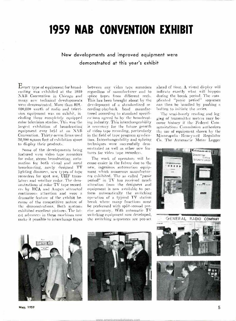
The semi -hourly reading and log- ging of transmitter meters may be- come history if the Federal Com- munications Commission authorizes the use of equipment shown by the Minneapolis - Honeywell Regulator Co. The Automatic Meter Logger
mallag.1111r GENERrAL RADIO COMPANY
May, 1959 5
www.americanradiohistory.com

. would complete the present systems used for unattended transmitter op- eration. Nineteen different circuits can be recorded on a 12 -inch w:de chart. The logging can be done either at the transmitter or at a remote point by telemetering the information from the transmitter. The Automatic Transmitter Logger could provide a more complete and accurate record of transmitter per- formance than is possible now by manual observation. The equipment automatically sounds an alarm if any meter reading deviates from its assigned value. This type of equip- ment actually is not a new develop- ment, as it has been used for years in other industries; however, its ap- plication to broadcast transmitters is relatively new. Since automatic logging in lieu of manual reading and recording is not authorized un- der present regulations, the Nation- al Association of Broadcasters, in cooperation with WTOP, Washing- ton, D. C. and WSJS, Winston- Salem, N. C., will petition the FCC to authorize industry use of automa- tic logger records as official trans- cripts. This action is expected to be taken later this year when experi- mental tests are completed.
Automation in programming also was being shown by a number of exhibitors. These systems using both tape and disc enable a station to prepare up to 24 hours of program- ming in advance. Since many broad- casters are entering into multi -pro- gram operations such as an AM pro- gram, an FM program, and one or more multiplex channel programs, it is becoming increasingly necessary to simplify and streamline the task of handling the technical operations for these programs. The equipment on display could handle record pro- grams, station breaks, newscasts and network switches. Timing is
kept extremely accurate by the use of time clocks.
Another type of automation which is offered to television stations con- trols slide changes, lighting, special effects and any function suitable for electric remote control. This is the Telemation Control sold by Tele - Prompter Corp. This system uses IBM type cards which are punched to operate the desired circuits. The automatic card reader accepts 150 of these cards, each of which has 12 positions where a punched hole
6 BROADCAST ENGINEERING
www.americanradiohistory.com

will cue an operation of that respec- tive channel.
The increased use of transistors and other semiconductor products was apparent in this year's exhibit. The use of these devices means added advantages to the broadcast- er in lower power consumption, greater reliability, less heat and smaller size for equipment. Equip- ment on display using transistors included transmitters, sync genera- tors, miniature image orthicon or- bitor tracker systems, audio con- soles, power supplies, tape recorders, switchers, and amplifiers. In dimmer controls the use of the silicon -con- trolled rectifier offers new advan- tages. The size and weight of light- ing control equipment can be re- duced as much as 95 per cent. Other advantages are lower temperature, less noise, less maintenance, higher efficiency, quicker response and greater flexibility.
Many new and unique equipment items were on display which offer the broadcaster an opportunity to increase his service to the public. Weather radar is an example of spe- cial services which television sta- tions in particular can offer. With
this equipment a station can show its viewers actual weather condi- tions as they appear on the radar scope. During severe weather dis- turbances, thunderstorm activity can be observed on the scope and a simultaneous report made to the viewers. Collins Radio Co. and RCA both offered this type of equipment.
Equipment which offers an oppor- tunity to develop individuality and personality for a station also at- tracted considerable interest. An ex- ample of this was the reverberation unit shown by Electronic Applica- tions, Inc., which enables a station to add a natural echo of up to 41/2
seconds. This could be used to add a live quality for an announcer's voice or other program material, or for use in developing unusual com- mercials. The unit is approximately 98 inches by 51 inches by 13 inches.
The NAB Convention exhibit is a once -a -year opportunity for those interested in broadcast equipment to see all of the latest apparatus required to build and operate a sta- tion. Many of the developments and systems shown will be described in detail in future issues of BROADCAST ENGINEERING.
May, 1959 7
www.americanradiohistory.com

NAB ENGINEERING CONFERENCE
Many papers covering current technical topics were read
at the I 3th annual Broadcast Engineering Conference
BROADCAST engineers attending thy 1959 NAB Engineering Conference heard approximately 18 papers which discussed new developments in AM, FM and TV broadcasting. Many of the topics have been discussed else- where in this month's issue of BROAD-
CAST ENGINEERING, and others will appear in later issues. The engineer- ing problems facing the industry to- day and the trends which broadcast technology is taking were indicated by the topics discussed at this year's meeting.
The Conference was opened by the presentation of the results of the two -and -a -half year study by the Television Allocation Systems Or- ganization to the Federal Communi- cations Commission. The import- ance of this report, which gives the results of the study of comparisons between UHF and VHF television channels, to the FCC was indicated by the fact that the report was pre- sented in loose form so that the Commission may have its benefit without waiting for the printed cop- ies. The Commission has indicated that the solution of the television allocation problem is one of the major issues facing it.
Since this is the era of higher and higher towers, several papers dealt with the problems which have de- veloped because of this trend. J. Roger Hayden, manager, commer- cial sales, Tower Division, Dresser- Ideco Co., delivered a paper deal- ing with the problems of vibrations in guy wires and antennas which have arisen to plague the structural engineer. He described experiences which illustrated thes- problems and told how they could be solved. He said that extra braces in a free- standing tower can prevent wind- storm vibrations that generate noise that sometimes sounds like "a pa- rade of garbage cans". "Weights
strung on guy wires of supported towers," he said, "will stop annoying galloping undulations that could lead to mental fatigue and damage the tower." One of the difficulties is that designs are calculated for static loads whereas the load is actually dynamic. A film of the destruction of the Tacoma bridge caused by vibrations demonstrated what could happen to large metal structures due to vibrations.
The discussion of a new tower lighting and marking system by Or- rin W. Towner, director of engineer- ing for WHAT, Louisville, Ky., was also timely in this day of the tall tower. Mr. Towner told the Con- ference the new tower lighting and marking system he recommended was based on four years of study of the system now in use, tests with models, and results with an experi- mental WHAS tower near Louis- ville. He quoted a commercial pilot with more than 20 years of flying experience as saying, "The WHAS tower's multiple beacon was the best obstruction lighting I have ever seen."
The filtered red light system now used, according to Mr. Towner, is only 10 to 15 per cent as efficient as unfiltered white light. He rec- ommended multiple white beacons placed at regular intervals along the tower all synchronized to flash once every two seconds. He said black and white offers the best possible contrast and should be used in bold alternate stripes to provide better over-all visibility. "The internation- al orange now used with white," he said, "has less reflectance than black, loses more in weathering and does not offer as great a contrast with backgrounds in some geographical areas." Mr. Towner said all towers should be equipped with photocells
to turn on the lights when daylight fades or on dark dreary days and to turn them off again when the sun is out. Sun reflectors were recom- mended for daylight use to help pro- vide contrast between the tower and its background. The solid circle of white or marble chips 100 feet in diameter should be constructed at the base of the tower with a narrow circle of the same material cutting through each guy anchor.
The trend toward the use of semi- conductor products was brought out by a number of papers. Lynn R. Zellmer of General Electric Co. de- scribed the use of germanium recti- fiers and silicon rectifiers in General Electric products. He discussed the problems encountered in the design of semi -conductor plate supplies which include rectifier selection, adequate surge protection, inverse voltage distribution, and corona sup- pression.
A paper was given by J. W. Went- worth of the Radio Corp. of Ameri- ca which explains the basic princi- ples of transistor operation. Since transistors are beginning to appear more and more frequently in both audio and video equipment where their small size, low power require- ments and long service life offer attractive advantages to broadcast- ers, broadcast engineers should be- come familiar with the benefits and limitations of transistors. He pointed out that the advantages of long life, low power requirements, reliability and versatility of the transistor were offset by the limitations of poorer frequency response, power handling capability, temperature sensitivity, non -linearity and rapid vulnerabili- ty to overstress.
A paper was given by Herbert R. Moore of Kliegl Brothers and Albert W. Malang of the American Broad -
8 BROADCAST ENGINEERING
www.americanradiohistory.com

casting Co., describing the use of silicon controlled rectifiers in TV lighting dimmers.
The silicon -controlled rectifier re- duces the size and weight of light- ing control equipment as much as 95 per cent. It also makes possible equipment that operates at far low- er temperatures, with less noise, less maintenance, higher efficiency, quicker response and greater flexi- bility. SCR dimmers are now avail- able that will handle up to 5,000 watts of lighting power with only .0015 amperes of control current. Each dimmer uses two rectifiers back to back. One rectifier controls the positive phase of an alternating cur- rent, the other controls the negative phase.
The planning, construction, and operation of a reversible intercity microwave relay system between WBTV in Charlotte, N. C., and WBTW in Florence, S. C., a dis- tance of 93 miles, was described by M. J. Minor, engineering manager for Jefferson Standard Broadcast- ing Co. The system is designed for remote control, reversible transmis- sion and includes three unattended repeater stations. The system is capable of monochrome or color video transmission in either direc- tion, with television audio contained within the channel as a diplexed sub -carrier signal. A single telephone line is used as a medium for switch- ing signals and for supervising the system.
In the field of automation James B. Tharpe, president, Visual Elec- tronics Corp., delivered a paper de- scribing TV program automation, which appears in this issue.
The FCC experiences with re- mote control of broadcast transmit- ters were described by Harold L. Kassens, Chief Aural Existing Faci- lities Branch, Broadcast Bureau of the FCC. He pointed out that the operator of the remote control equipment must be an employee of the station. This would prevent a station from installing remote equip- ment at the office of an answering service or other commercial service. Mr. Kassens discussed the remote operation of 50 kilowatt transmit- ters and stations with directional antennas. He indicated that stabili- ty and proper adjustment must be proven and that readings taken at each monitoring point for one year must be furnished the Commission.
In answer to questions concerning improper operation due to defective equipment Mr. Kassens advised, "If anything goes wrong, fix it fast."
Dr. George H. Brown, chief en- gineer, Industrial Electronics Prod- ucts, RCA, described a simplified means of proceeding from a desired directional radiation pattern to a physical radiating structure. He showed how a wide choice of cur- rent distributions or array configu- rations for obtaining a single de- sired pattern become available by adding to the real pattern another pattern in an imaginary zone.
A new approach to TV antenna specifications was discussed by Don- ald W. Peterson of RCA Labora- tories. It was brought out that the present specifications are not capa- ble of conveying to the broadcaster an adequate description of the sys- tem. A new approach would relate system performance and antenna and transmission line specifications positively and unequivocally.
A panel composed of leading au- thorities in the technical and pro- gramming aspects of video tape re- cording discussed SMPTE Stand- ards, maintenance, adjustment and operation of the recorder and prob- lems involved in the production, scheduling and syndication of pro- grams and commercials.
Mr. Dwight Harkins, of Harkins Radio, Inc., described how cross- talk problems in multiplexing had been isolated and corrected, and emphasized the importance of prop- erly installing multiplex receivers and their antennas. An article by Mr. Harkins, which describes the conditions which are necessary to permit perfect multiplexing, is in- cluded in this issue.
The first recipient of the National Association of Broadcasters Engi- neering Achievement Award was presented to John T. Wilner, vice- president and director of engineer- ing for radio and television, the Hearst Corp. The award was made in recognition of his outstanding contribution to broadcast engineer- ing through his work on the image orthicon saver.
This year's engineering conference covered many aspects of broadcast- ing. BROADCAST ENGINEERING plans to carry articles in future issues covering details of these subjects and many others.
Microwave video relaying equipment was displayed and discussed at the Convention this year.
Standards and problems in video tape recording were the topics of a confer- ence panel.
Inspecting the silicon controlled recti- fier which is used in new TV lighting dimmers.
May, 1959 9
www.americanradiohistory.com

STEREOPHONIC BROADCASTING
MANY PROBLEMS HAVE TO BE SOLVED
BEFORE A STANDARD METHOD IS ADOPTED
STEREO is the magic word which has captured the public's fancy in recent years. First it was stereo on tape, next the tremendous growth of stereo on discs and then the advent of stereo broadcasting. Every major city has introduced this new form of broadcast entertainment to its listeners and all indications are that the public will accept stereo broad- casting as it has accepted stereo on tape and disc.
The initial method of stereocast- ing used by broadcasters uses a com- bination of two transmitting chan- nels such as AM -FM or AM -TV which is the only system approved for general use by the F.C.C. at the present time. This method does not require a change in transmission standards; however, it is not con- sidered a permanent system because it is uneconomical of spectrum space and is not compatible for single re- ceiver reception since it provides the monaural listener with only one channel.
How A System Will Be Selected Many systems for the transmis-
sion of stereophonic broadcasts have been suggested. Since a standard system will have to be selected, the F.C.C. must establish technical standards for stereo broadcasting. The broadcast industry is faced with producing a system which will equal in quality the other stereophonic re- producing systems already intro- duced to the public. This indicates that a careful study must be made of all systems before a decision is reached. Two steps have been taken toward the selection of a technical standard of transmission for stereo - casting. One is a Notice of Inquiry by the F.C.C. whereby written com- ments may be filed on or before June 10, 1959, concerning stereo. The Commission is including the stereo question in its previous broad in- quiry into the techniques and po- tentialities of FM multiplexing be- cause of the keen awareness of and widespread interest in FM stereo-
phonic programming among broad- casters, equipment manufacturers, trade associations and listening groups. Questions Raised by FCC
The Commission has asked for comments on these questions:
(a) Should stereophonic broad- casting by FM broadcast stations on a multiplex basis be permitted on a regular basis, and if so, should such broadcasting take the form of a broadcast service to the general pub- lic, or should it be available only on a subscription basis under Subsidi- ary Communications Authorizations, or both?
(b) What quality and perform- ance standards, if any, should be ap- plied to a multiplex sub -channel used for stereophonic broadcasting?
(c) Should a specific sub -carrier frequency or frequencies be allocated for stereophonic broadcasting?
(d) Should the quality and per- formance standards applicable to the main channel be further relaxed, be -
I0 BROADCAST ENGINEERING
www.americanradiohistory.com

yond the point already permitted for SCA operations, to accommodate stereophonic broadcasting and, if so, to what extent?
(e) What transmission standards regarding cross -talk between the main channel and stereophonic sub - channel should be adopted?
(f) Should FM broadcast stations engaging in stereophonic broadcast- ing be required to use a compatible system which allows listeners tuned only to the main channel to hear an aurally balanced program?
The second step taken has been the establishment of the National Stereophonic Radio Committee, sponsored by the Electronic Indus- tries Association, which will under- take the study of various problems of stereo broadcasting in AM, FM and TV. The NSRC is comprised of six panels which will investigate and evaluate systems specifications, in- terconnecting facilities, transmitters, receivers, field testing and the sub- jective aspects of stereo. It is esti- mated that this study will require one year.
Approximtaely 20 different sys- tems have already been proposed and more will be announced. This indicates that the final selection and standardization will not be a simple matter. Some systems are applicable for AM only, some for FM only, and others can function on either me- dium. The FM systems propose the use of a sub -carrier using multiplex- ing techniques.
Multiplex Stereo Some of the problems to be de-
cided in multiplex stereo are the modulation level and sub -channel band width required. The higher modulation level provides an opti- mum transmission for the stereo channel; however, the modulation range is reduced for the monophonic listener. Cross -talk problems may also occur in some transmitters at the higher modulation levels. The band width question revolves around the determination of whether or not the stereo effect is dependent on the full audio frequency range, or if only certain mid -range frequencies are necessary to provide the effect. If it is decided that it is necessary to have only a limited band width, then ad- vantages can be gained in modula- tion levels and additional services can be provided in the multiplex spectrum. This is a subjective mat-
ter with advocates for both full band width and limited band width. The proponents for limited band width would still provide a full range sig- nal by combining the signals in the frequency ranges outside of the sepa- rate stereo range. Among the sys- tems using FM multiplex techniques are the Halsted, Crosby, Calbest and Philco.
The Halsted system utilizes the main broadcast channel for one stereo side and a multiplex channel for the other side. Advantages claimed for the Halsted Stereoplex System are a compatibility with present AM -FM stereo transmissions which would enable the FM multi- plex audience to grow as adapters are installed in homes without cur- tailing present stereo transmissions during the transitional period and the retention of high overall per- formance capability of the main channel under multiplex transmis- sion conditions.
The Crosby system transmits the full program material on the main channel and one stereo source on the multiplex channel. Thus, a mono- phonic listener receives a complete compatible program. By means of the sum and difference technique two seperate channels are provided for stereo listeners. Advantages claimed for this system include a signal -to -noise -ratio gain for the two channels of the stereo system and a balancing of the frequency response realized on the two received channels.
The Calbest system also transmits the sum of the two stereo com- ponents to provide a compatible main program channel. However, the multiplex channel carries only one of the stereo components and is limited to 3500 cycles. Calbest has cited physical, psychological and other research data which indicate that frequencies below about 180 cycles and above 3500 cycles play a
negligible part in stereo from the standpoint of the listener. Thus, ad- vantages in frequency spectrum and signal -to -noise -ratio can be gained by using the restricted band width. In this system the frequencies above 3500 cycles are evenly divided be- tween the two channels.
The Philco Corp. has proposed a system using another technique to derive separate stereo channels from a compatible main program channel. Their system utilizes the sum signal
on the main channel, the difference signal in a band from 32 KC to 17 KC and a reference carrier signal of 32 KC. The audio sum and differ- ence signals are obtained by single - side band AM modulation tech- niques. This combined signal then modulates the FM transmitter in the normal manner. AM Stereo
Stereo broadcasting, of course, will not be restricted to FM stations. The double side band characteristics existing in the AM signal make it possible to add the required infor- mation for two -channel stereocast- ing. Numerous systems have been proposed which will provide compat- ible AM stereo. One of these was demonstrated at the recent NAB Convention by the Kahn Research Laboratories. This system provides an adapter which produces two in- dependent side bands which are in- dependently modulated by the two stereo channels. The resulting en- velope wave has the same spectrum requirements as conventional AM. The envelope wave produced by the adapter permits independent upper and lower sidebands to be demodu- lated by standard AM detectors. Therefore, stereophonic reception can be achieved by simply tuning two receivers to the respective upper and lower sidebands. Receivers with single control tuning, dual audio channels and other features could also be introduced to receive the system. An interesting feature of this system is that the fidelity of reception from the average receiver is improved because the set is tuned slightly off -carrier, thus extending the band width of the receiver side - band.
The Philco Corp. has developed a compatible AM system using both amplitude and phase modulation. The amplitude modulation is pro- portionate to the sum of the stereo signals. The phase modulation is de- termined by the higher frequency components only of the two stereo signals. The two stereo signals are applied to separate identical modu- lator stages of a transmitter. The carrier wave from the master oscil- lator is amplified and split into two components phased 90° apart. Each phase is applied to one of the modu- lator stages and the outputs of these modulators are combined in a di- plexer suitable to the transmitter
May, 1959
www.americanradiohistory.com
circuit requirements. The resulting carrier in the absence of all modu- lation is then midway or 45° from either of the carrier currents de- livered by the two modulators. During the modulation each carrier component from these modulators varies in amplitude only and may be modulated up to 100 per cent in con- ventional manner. The resultant car- rier being the vector sum of the two will also be amplitude modulated. At times when the signal is mono- phonic only amplitude modulation of the resultant carrier is obtained. For a stereo signal the two channels are different and both amplitude and phase modulation of the resultant carrier is obtained. Standard re- ceivers reproduce a full monophonic signal; however, a special receiver is required to produce stereo reception.
Another method of considerable in- terest which can be used for either AM or FM is the Percival Stereo Radio System. This system was demonstrated during the NAB Con- vention. The Percival System differs
in that it is transmitted as a single source with a control signal used to determine the direction of the sound source. The control signal is approx- imately 100 cycles wide and is trans- mitted on a sub -carrier in the case of FM or could be applied to the AM carrier by frequency modulating the main carrier or inserting it on a sideband.
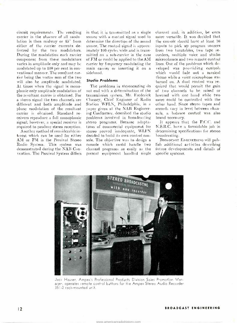
Studio Problems The problems in stcreocasting do
not end with a determination of the transmission system. Mr. Frederick Chassey, Chief Engineer of Radio Station WFLN, Philadelphia, in a paper given at the NAB Engineer- ing Conference, described the studio problems involved in broadcasting stereo programs. Because adapta- tions of commercial equipment for stereo proved inadequate, WLFN decided to build its own control con- sole. The objective was to design a console which could handle two channel programs as easily as the present equipment handled single
channel and, in addition, be even more versatile. It was decided that the console should have at least 16 inputs to pick up program sources from two turntables, two tape re- corders, multiple voice and studio microphones and two remote control lines. One of the problems which de- veloped was providing controls which would fade out a musical theme while a voice microphone was turned on. A dual control was re- quired that would permit the gain of two channels to be raised or lowered with one hand while two more could be controlled with the other hand. Since stereo tapes and records vary in level between chan- nels, a balance control was also found necessary.
It appears that the F.C.C. and N.S.R.C. have a formidable job in determining specifications for stereo broadcasting.
BROADCAST ENGINEERING will pub- lish additional articles describing future developments and details of specific systems.
Jack Hauser, Ampex's Professional Products Division Sales Promotion Man- ager, operates remote control buttons for the Ampex Stereo Audio Recorder 351-2 rack -mounted unit.
12 BROADCAST ENGINEERING
www.americanradiohistory.com

PLAYING SPOTS ON TAPE
Equipment has been introduced to play short recordings
conveniently and practically on magnetic tape.
THE GROWTH of the magnetic re- cording industry has assumed phe- nomenal proportions during the past decade. Since the end of World War II we have seen magnetic recording grow from the first wire recorders which were our original introduc- tion to the marvels of magnetic re- cording to audio tape recorders which gave the industry faithful sound reproduction indistinguishable from the original, data recorders which store millions of pieces of in- formation, and video recorders which can now record color television and play back with live quality.
The change in programming meth- ods by individual stations and net- works was revolutionary in the in- dustry with the widespread adop- tion of audio tape just as the devel- opment of video recording is cur-
rently changing television program- ming practices. The development of magnetic tape brought about econ- omy, flexibility and quality improve- ment for the broadcast industry.
However, since tape recorders were designed to play for relatively long periods of time, they do not provide the convenience necessary for on -the -air playing of spot an- nouncements. The time required to thread and cue up a spot and the problems involved in filing spots on tape reels has made it difficult to utilize tape for short duration ma- terial. Some stations häve attempted to overcome these problems by the use of multiple tape player systems and other improvisions. However, the lack of simplicity has discour- aged the widespread adoption of tape for spot use.
The Gates "Spot Selector" in operating position.
Now equipment has been intro- duced which makes it as easy, if not easier, to play spot announcements on tape as on discs. Not only one system but several were introduced at the NAB Convention this year to. break through the spot limitation barrier. The methods shown included the use of a magnetic tape belt 13 inches wide, tape cartridges, mag- netic discs and standard tape reels with equipment to select automati- cally the desired spot announcement.
A spot tape recorder using a 13 -
inch wide magentic belt has been introduced by the Gates Radio Co. This unit accommodates 101 spot announcements which can be up to 90 seconds in length. Each announce- ment, jingle, theme or other material is selected from the front panel by an indexed control knob. At the com- pletion of tape travel, the tape auto- matically rewinds, stops and cues up, and is ready for the selection of the next announcement. Recorded ma- terial can be erased and new ma- terial recorded just as on any other tape recorder without damaging re- cordings on adjacent tracks. In a paper given by Jay Blaksley, Man- ager, Audio, for Gates Radio Co., it was stated that five requirements are desirable for a spot tape re- corder: (1) The machine must have good frequency response and low noise and distortion. This require- ment is the same as that called for in any commercial tape recorder. (2) The machine shall be of such physical size that it can be either rack or desk mounted. (3) The ma- chine shall have a time capacity of over one minute for each spot. (4) The machine shall be capable of
May, 1959 I3
www.americanradiohistory.com

automatically cueing and rewinding each spot announcement. (5) The machine shall be capable of record- ing and reproducing over 100 spots without removing the reel of the tape from the machine.
Gates has designed its recorder to satisfy these requirements. Auto- matic rewind and cueing are accom- plished by the use of two photo- electric cells. The tape rewinds after the 90 -second interval and auto- matically cues to the correct indexed starting point. The scale on the front of the machine is graduated into major divisions of i through 10. Each of these divisions is further subdivided into letters A through K. These divisions provide for the in- dexing of 101 separate recording tracks. The front panel contains the necessary switches for accomplish- ing record/play functions, bias metering and volume indicating as well as the start/stop and manual rewind switches. The machine can also be remote -controlled. Rewind time of the tape is accomplished in 20 seconds; however, manual rewind is possible at any time during the limit of tape travel.
The Collins Radio Co. has intro- duced a system using tape car- tridges. In this system each car- tridge contains one announcement or other recorded material. This sys- tem is known as the Automatic Tape Control. To play a cartridge it is in- serted into a slot in the unit where it automatically engages the record- ing head and starts the capstan motor. A "Ready" light is illumi- nated on the control panel indicating that the spot is ready to play. The announcement is played by depress- ing the "Start" button which changes the function lights from "Ready" to "Run", thus indicating the mode of the machine.
After the recorded material has been reproduced, the tape continues moving across the play-back and tone control heads until a tone burst, which is recorded on the tape, stops the equipment which then returns to the "Ready" position. In the play- back function, the Automatic Tape Control is never stopped manually, the stop impulse is generated by the tone control circuit which is arranged so that the announcement is prop- erly re -cued and ready for re -play at the end of the tape travel. Both a record/play-back unit and a play- back only unit are available from
Collins. As an accessory an auto- matic audio switcher is available which will feed multiple automatic control units into a single channel of a studio control console. Remote control of the unit function is also provided. Three sizes of cartridges are available which provide from 40 seconds to 40 minutes of recording time.
A system whereby up to 99 spots of any length can be recorded on a standard tape reel and any one of these spots automatically selected and cued up was demonstrated by the Schafer Custom Engineering Co. This machine, called the Spotter, consists of a separate console -type control head plus a tape recorder rack and other circuitry. To use the Spotter, all announcements are pu on tape and each is assigned a num- ber up to 99. Then by pushing the
buttons corresponding to the desired spot number, the proper announce- ment is automatically selected and positioned for playing.
Another approach to the use of magnetic recording for spot use is the RCA Magnetic Disc Recorder. This unit combines the advantages of magnetic tape with those of phonograph discs by using pre - grooved magnetic discs the same size and shape as conventional 45 -rpm records. These are played on a turn- table equipped with a tone arm using a magnetic head. The discs can also be used in automatic turntables and, by means of a cue signal, the discs will cue into the start of a message and trip out the change mechanism at the end of the message. RCA has also introduced a multiple track, wide -belt machine.
(Continued on page 36)
Harold E. Fellows, President of the National Association of Broadcasters, in- spects the Collins tape player. Forest Wallace, left, points out the features of the equipment.
14 BROADCAST ENGINEERING
www.americanradiohistory.com

HOW TO GET THE MOST OUT OF MULTIPLEXING
This article details the many pitfalls of FM Multiplexing at both the transmitter and receiver end. From his experience in modifying over 50 FM transmitters, the author details the necessary conditions which will permit perfect multiplexing.
IN ORDER to obtain satisfactory mul- tiplexing the system concept must be used. The transmitter, together with its antenna, must be operated correctly in order for the receiver to function properly. Not only must the transmitting equipment create a subcarrier that is free of distortion but it must transmit without adding crosstalk. The receiver in turn must amplify the signal and detect it without contributing noise, cross- talk or distortion of its own.
The ideal set-up would be to have a transmitter that is designed and built to handle multiplexing and to use a transmitting antenna that is also designed and built for multi- plexing. Thus far this author has devoted his time to the modifica- tion of existing transmitters to per- mit multiplexing, and in the course of so doing has uncovered many things that cause unsatisfactory op- eration.
The whole problem at the station has revolved around eliminating crosstalk interference of the main channel modulation products get- ting into the subcarrier. Some of the things occurring at the transmitter were:
(1) Multipliers created phase dis- tortion, resulting in crosstalk. Improper couplings between stages caused crosstalk. Regenerative amplifiers caused crosstalk. Any mistuning caused cross- talk. Any conditions in the radiat- ing system that presented a reactive load to the transmit- ter as indicated by high VSWR would cause crosstalk.
(6) RF pickup in audio circuits caused crosstalk.
By Dwight Harkins HARKINS RADIO, INC.
4444 E. Washington Phoenix, Arizona
During the course of installing our multiplexing exciters throughout the country, these and many other sit- uations were encountered and cor- rected. A multiplexing station moni- tor was developed and proved very valuable in adjusting each individ- ual transmitting system to give proper performance. The mysteries of crosstalk no longer existed and the station operator had clearly de- fined corrective measures he could apply if the economics of the situa- tion permitted it.
Even though the transmitting problems were licked and a good signal was being generated by the station, the existing receivers were found to be contributing serious crosstalk. Even though the over-all system, including the receiver, was not perfect, background music cus- tomers were being served on a wide- spread basis. Commercially success- ful multiplexing became a reality. The receivers were out earning mon- ey. Cooperation between engineer- ing and managemnt had brought about successful operation in many areas.
The following techniques were used. First, by holding back main
channel modulation and by enforced gain riding and efficient peak limit- ing the main channel break through was minimized. Automatic subcar- rier muting between music selec- tions was perfected. Sta -levels and uni -levels were used on the subcar- rier to insure highest modulation at all times. Volume controls and tone controls were set for balance at the locations and served to keep the presence of crosstalk least noticed.
These and other similar tech- niques were considered par for the course. Coupled with the honest motive to make multiplexing work, a large segment of the new industry did just that.
In the face of the widespread variation of results obtained, many station owners were reluctant to get into multiplexing. This could be understood, because not only was there a lack of new equipment or a complete multiplex transmitter, but there was no widespread informa- tion regarding the methods that could be used to permit successful multiplexing with existing equip- ment.
With a transmitted signal that (Continued on page 36)
The HARKINS Multiplex receiver which features an I.F. amplifier operating at 23 Mc. for high phase linearity and a subcarrier filter that enables full 10 Kc deviation.
May, 1959 IS
www.americanradiohistory.com

; t: --t ,.
0 silk. *dill0 s «4 c .
00«00``:4 4114:6i. *ari iii c c ç %. 4 c-4.
`' 0 0 +1 il. ` : . p
..
di00411006 1, t t. C C. 4
o `
ON AIR e t t t
alF i aK eairss tete«) iti tiae Q
<
s00a«00 Ctttt C ttaDi ti tii 444
S ---1 G- t fie* see 00+ sssa :sc' -e. C t
4 :
G C. sss
Ocre 04 c-t fisf m004eri,
c
c sws+ 6ss>
s4e°041041k406.4b' lie.abde Akiit
` O Opá::: .. `si *MP
e 0 41,64k0 f+ 6s' ::110 `ii f"ü c
6 c 4 t *riiiiEir Pet ,.**i,
t c
die 14440 6,
to 110w btri+ if 6 + i+ t 6, ir> ir, ir.. ir 6. 6' 6, 6. 6 aì 6 * ir 6 6 6 6 6 6 6 6 6 6 ir
ee4 eeet tee
By
JAMES B. THARPE
President Visual Electronics
Corp.
AUNITIZED electronic television program automation system is de- scribed which can be built up to pro- vide varying amounts of station automation as required in the sta- tion development-from automating only the "panic" station break pe- riod to automation of the largest TV broadcast centers desiring to run completely automatic operations programmed by punched cards, punched tape or other means.
The system features maximum convenience and minimum confusion due to its "shift" storage and display system. All events which have been set into the equipment are continu- ously displayed to the operator in the order in which they are to occur. Changes or corrections can be made on any stored event at any time. When an event occurs, the indica- tion describing it disappears from the top of the panel; all other indi- cations shift up one position. Vacant positions at the bottom can be filled at any time either manually: or by a punched card or tape device
In order to provide ultra -reliability in this equipment, Beam Switching Tubes with 50,000 -hour life expect- ancy are used for the heart of this system. Mercury -wetted contact re- lays rated at one billion operations are used for the shift function.
16 BROADCAST ENGINEERING
www.americanradiohistory.com

A BUILDING BLOCK TELEVISION
PROGRAM AUTOMATION SYSTEM
Introduction This paper describes a unitized
Television Program Automation Sys- tem which can provide a simple manual preset for handling the "panic" station -break period and can be expanded step-by-step as sta- tion automation develops to provide complete automatic operation of all master control switching and related functions for the largest television broadcast center through punched cards, punched tape, or other pre- programmed storage devices. The system incorporates unique features to make its operation clear and straight forward and to allow for any last minute corrections or changes. In case of any unforeseen happening this automation system can be controlled by an operator to take care of the special situation rather than have the operator be forced to shift to "manual" opera- tion at a most difficult time. As sys- tem reliability must be of the high- est possible order, "50,000 -hour" life potential components have been used for the key portions of the sys- tem. Construction is modular and so arranged that the system can be easily tailored to provide for the initial requirements of any station and expanded at will. All modules
are plug-in through "blue ribbon" connectors - even the key resistor and condensor groups are plug-in! If trouble does occur in one of the modular units the faulty portion of the system can be by-passed by patching and serviced later. The limited servicing and maintenance required can be easily accomplished.
General The storage -display panel holds a
series of preset stored events. (Each occasion something is to happen is an "event"-what is to happen is a "function".) The system will store a number of "events" scheduled to occur in sequence and each event will have stored the video and audio "functions" which will go on the air at that occasion. Thus a number of events is preset into the storage -dis- play panel-each of which specifies the particular video and audio func- tion to occur at that "event". These events are stored and displayed on the panel from top to bottom in the sequence in which they will occur. '(Set in the panel here shown is se- quence to occur as follows: Event No. 1, video function .. . audio func- tion ...; event No. Q, etc.)
Correction Change or correction of any func-
tion in any stored event may be
quickly and easily accomplished by simply touching a front panel "cor- rection" push button associated with that function group. The unit will rapidly sequence through the func- tions available in the group and the desired one may be set by releasing the push button as it appears. This procedure is rapid and quite satis- factory for making corrections or changes in previously stored infor- mation when necessary.
An outstanding feature of this system provides that when the up- coming event occurs (goes on the air) that event leaves the top row on the panel and all succeeding events shift up one row to provide again a panel display showing the next upcoming event in the top row and all succeeding events in their order of scheduled occurrence read- ing from top to bottom. When this next event occurs (goes on the air) all succeeding events again shift up one row to continue to provide at all times a display showing the next up- coming event at the top and each scheduled succeeding event in se- quence reading down the panel. This continuous in -sequence display of upcoming events provided by the "shift" action of the storage -display
mey, 1959 I7
www.americanradiohistory.com

panel provides clarity in operation not heretofore available in such sys- tems. Manual Feed -In
Information is fed -in and stored ill the storage -display panel through a remote control panel by the momen- tary grounding of a low voltage low current DC contact associated with the function desired for a particular event. When all functions for a given event have been so set-in, the system automatically shifts this stored event up the panel to the last open event row. That is, an event is set into the bottom row and auto- matically shifts up the board to fill the vacant row immediately follow- ing the series of stored events. Thus a complete sequence of events can be set-in from the remote operating position and the event being set-in can be checked and corrected from the remote position and then re- leased to shift up as described. In this manner the operator can load up the panel for a station break pe- riod by reading down the program schedule (log) and setting -in the de- sired events in sequence from a sin- gle push button control panel - checking and correcting if necessary as he goes. Tape Feed -In
The simplicity and straight for- wardness of this shift display ar- rangement is evident for manual op- erations. The features provided also lend themselves ideally for expan- sion from manual feed -in of infor- mation to feed -in from a punched tape or punched card system. When using punched tape, as each event occurs, the stored information shifts up as described-leaving the bottom row empty. The tape is advanced one event through the tape reader and read out. Its information is set- in the bottom row. As the next (top row) event occurs, the board will again shift up and the tape again advance one event causing the tape reader to again fill the bottom row. Thus the storage -display panel will provide storage and read out in depth for upcoming scheduled events which can be easily read, reviewed, and quickly corrected or changed if nec- essary prior to going on air - thus eliminating the inflexibility of the tape system alone which cannot be easily read or changed. Card Feed -In
The unique feature provided where- in an event set in at the bottom row will automatically shift up the panel
to the open position immediately be- hind already scheduled events pro- vides the ultimate in adaptability for punched card fed systems. For instance, if a station adopts a punched card system it would not use a card for each event-it would likely use a single card to schedule a commercial spot-this might call for a sequence of several events- say four slides plus a film clip, etc. This card could carry accounting and other information: account name, spot identification, contract number, frequency discount, etc. When this card dropped in the card. reader, so timed that several events were open at the bottom of the storage -display panel, its event -function information would be automatically set-in in se- quence and each shift up the board in turn, stacking in the several events called for by this card, for this spot, these being set-in in sequence and immediately following the last pre- viously set-in event.
Thus, this system provides stor- age and display in depth for a num- ber of events, always displaying them in their upcoming order from top to bottom of the panel with the next upcoming event always in the top row. Events may be scheduled and fed -in manually from a single remote control panel position or may be fed -in in sequence from punched tape, punched cards or other similar systems. An event is fed -in the bot- tom and automatically shifts up the board to fill the next in -sequence open event position. "Take -Button"
In a simple manual preset system, the top row event may be made to occur by hitting a "take -button" which will put it on the air. Thus, if a station break is preset as a series of events, each succeeding event may be put on by hitting the "take -but- ton." (As events occur and the stored schedule shifts up clearing the lower rows, additional events may be set- in.) A simple manual feed -in, manual take preset system will provide a great aid to any station large or small for relieving operator burden during "pressure" station -break pe- riods as it allows him to think through, plan, and preset a sequence prior to the critical time - and to look at the preset sequence displayed in full before him for review, correc- tion, or change prior to initiation. Time
Operation may be augmented by the addition of a "timed" system
such that each stored event will oc- cur automatically at a pre -scheduled time rather than by manual "take - button" action. Timed systems are arranged so that when the time set- in for an event coincides with the time on the system "clock" or timer, that event receives an "operate pulse" and its designated functions are put on the air.
Count Down Time The simplest timed system is an
elapsed time or "count down" sys- tem which would be provided by the addition of three additional time storage -display units for each event on our panel-one for units of min- utes, one for tens of seconds and one for units of seconds. The "clock" in this system consists of a timer which is started by activating a "start" button at the desired beginning of a timed sequence of events. After starting, it advances in time in one second steps, counting down the top row event to time coincidence at 0:00. In our storage -display panel, events are stored in sequence each with the time interval from the pro- ceeding event. For example: we may have first slide 1 for 10 seconds, then slide 2 for 4 seconds, then film 1 for 20 seconds, then net.
We set-in: 0:00 S1
0:10 S, 0:04 F, 0:20 N
At the instant of "start" of the se- quence, the first stored event (S1) 0:00 would occur. The next stored event (S2) then shifts up to the top row and the advancing "clock" timer counts it down 9-8-7-6-5-4-3-2-1 to 0:00 and it goes on the air. Then the next scheduled event (F1) shifts up to the top row, is in turn counted down 3-e-1 to 0:00, etc. When zero time coincidence occurs for each event, that event is made to occur and remaining scheduled events shift up, always maintaining complete in - sequence display from the top read- ing down.
Complete Time A complete timed system would
incorporate the following: 1. A "True" time master clock
supplying a time base of one second pulses.
2. A second, electronic clock which normally follows the time master clock stepping at a one second rate -but which can be pulsed much faster to run ahead or stopped as described below.
3. A. 10's of minutes time column
18 BROADCAST ENGINEERING
www.americanradiohistory.com

(units of hours and 10's of hours may also be included-though not essential for most operations). In normal operation all events are set- in in scheduled sequence with their program log time, the electronic clock follows the time master clock and establishes time coincidence with the top row event at its designated time - thus causing that event's functions to go on the air automati- cally at that time.
In cases of failure to follow the exact preplanned time schedule of events stored according to log time, an "approximate" time base is used to maintain each event in its proper sequence time interval. For example, suppose we have a station -break all set-in scheduled to begin at 29:30 and unexpectedly the net leaves early at 29:13. As 17 seconds of dead air time is undesirable, the operator would push the "approximate time TAKE" button which would feed a rapid sequence of pulses to the elec- tronic clock, causing it to advance rapidly to time coincidence with the first event putting it on the air. The electronic clock then reverts to one second steps and the system contin- ues to operate on the "approximate time" of the now reset electronic clock.
Likewise, if the President speaks over 1:23 and the net is lati leaving, the operator can press "approximate time HOLD" which will stop the electronic clock until released. Upon release (net leaves) the operator would switch from "approximate time HOLD" to "TAKE" as de- scribed above and pick up his preset log sequence of events at their prop- er intervals from the now reset "ap- proximate time" condition. When such a break is completed, time may be shortened in any interval by rap- idly advancing to the next interval by the "TAKE" or time may be in- creased in any interval by the "HOLD". Thus the operator may get back on true time as the oppor- tunity arises in the same manner which he does today (without auto- mation) .
A control panel switch allows re- setting of the electronic clock to the "TRUE" clock when desired to au- tomatically reset to exact true time. Relative Time
Another unique feature of this sys- tem allows for the electronic clock to be used to provide "relative time" as well as "approximate time". For example, if during a net show, the
station were to be scheduled to take a one minute break to be on arbi- trary cue rather than on specific time, the one minute break to come in at the unknown time on cue could be set up on "relative time" from 0:00 for beginning of cue. The elec- tronic clock would be re -set to 0:00 and started in one second advances from the operator's pushing the "relative time START" button on cue. When the relative time sequence is completed, the electronic clock is re -set to the TRUE time clock. Spe- cial features in this system allow for intermixing the storage of TRUE and relative time events with the system automatically changing time base due to coding of the relative time events by having only three time digits displayed (10's of min- utes indicator dark for relative time events) .
Anticipation A time base system allows the in-
corporation of an additional very desirable feature of this system. Con- sider the matter of a film projector with a 4 -second roll time or a VTR with a 7 -second roll time. In the simple manual preset system, one manual operation is required to "roll" the projector, a second to "take" the projector.
In the timed system, there are three possibilities:
1. To schedule projector "roll" and film "take" as two separate events 4 seconds apart. This takes up a lot of events.
2. To schedule projector "roll" only and through a 4 -second fixed time delay relay associated with that projector circuit have film "take" occur after this fixed delay. This necessitates scheduling the event 4 seconds (or 7 seconds, etc.) ahead of the program log on -air time -which is confusing. It also loses control of the time of the "take" event (set for a fixed 4 seconds) un- less special provision for override of each such fixed delay is provided.
3. Due to its storage in depth, the currently described system can be expanded to provide an "anticipate" circuit which, when events are sched- uled at on -air time per the program log, will provide automatic starting of machines at the correct interval before the event. For instance, pro- jectors 4 seconds before, VTRs 7 seconds before, etc. This tremen- dous advantage can be provided on elapsed or count down timed sys- tems for any events occurring after
the first seven seconds in the se- quence and in the more advanced timed system described for all timed events.
This anticipate circuit operates as follows: Time coincidence is estab- lished with the top row event of the storage -display board 7 seconds prior to on -air time. The storage -display panel operates in normal fashion; however, the selected event does not immediately go on the air as it leaves the top row but rather travels down a 7 -second "anticipate delay line" in one -second steps. This delay line stores the selected function in the same manner as the event functions on the storage -display panel but no display is provided (it is not neces- sary) and the selected function is advanced one position along the line each second by the incoming one - second timing pulses from the mas- ter clock system. Thus, a selected function leaves the top row 7 sec- onds before air time and goes 7 -6 -5- 4 -3 -2 -1 -on air. Along this delay line, each function has tapped off at the appropriate step, the "machine roll" initiate information, i.e., when VTR reaches step 7 (the first following the top row) the VTR machine is caused to roll. VTR function con- tinues down the line 6 -5 -4 -3 -2 -1 -on air, going on air at the scheduled time - and exactly seven seconds after VTR was "rolled". A selected film function would leave the top row 7 seconds before air time, travel 7-6-5-4 (here the tap -off to that ma- chine would cause it to roll) 3 -2 -1 - on air-film switching on air at the scheduled time-and exactly 4 sec- onds after the projector "rolled".
Note that two or more selected functions can be traveling down the "anticipate delay line" at the same time (in different sequence posi- tions). Therefore, the system does not jam for the required start time of any machine.
For example: Sequence (1) leave net Sequence (2) 2 second slide Sequence (3) take film
In this case, events would be scheduled according to on -air time.
29 30 leave net, take slide 29 31 29 32 leave slide, take film
but, due to the anticipate feature, the 29:30 event (slide) would leave the panel top row at 29:23 (7 sec- onds before air time) and start through the delay line. Likewise, the 29:32 event (film) would leave the panel top row at 29:25 (7 seconds
May. 1959 19
www.americanradiohistory.com

before air time) and start through the delay line. Thus they would progress through the delay line with film following behind slide by 2 steps (2 seconds).
Slide at: Film at: 29:22 top row second row 29:23 7 top row 29:24 6 top row 29:25 5 7 29:26 4 6 29:27 3 5 29:28 2 4 causing projector roll 29:29 1 3 29:30 on -air 2 29:31 1
29:32 on -air Building Block
The building block modules com- prising this system provide three events in a 7 -inch high standard rack panel. Thus nine event storage requires three 7 -inch panels, 12 events four 7 -inch panels, etc. For each horizontal event row there may be 6 ten -function groups on a 19 -inch wide standard rack panel, 8 on a standard 24 -inch rack, 10 on a stand- ard 30 -inch rack.
Function groups are available in multiples of 10, 20, 36 and 100. Ten takes one horizontal module space; 20 takes two; 36, or 100 takes three horizontal module spaces. Function group indicators may be numerical Nixies, alphabetical Nixies, or Neon tally clusters. In our model here, the time was displayed by numerical Nixies and video -audio functions by neon tally clusters. Complete free- dom of choice as to these display in- dicators is available to the station in this modular system. Reliability
The requirement to perform all of the vital functions concerned with putting a station's pictures on the air places a high premium on both visual and electronic error -free oper- ation. To provide for the highest order of reliability in this system, a study was made of the various ways that it could be built circuit -wise and an evaluation made of the vari- ous approaches found possible. Me- chanical stepping switches; relays, tubes, and transistors in both binary and decimal arrangements; magnetic storage elements, etc., all could pro- vide such a system. The most reliable combination of circuit elements was chosen from this evaluation and is incorporated in the present system. It consists of Beam Switching Tubes for storage and switching of group functions, Nixie or neon readouts, and mercury -wetted contact relays for transfer of events. Since the heart
of the storage -display system de- scribed consists primarily of these components, they are discussed briefly. Beam Switching Tubes
Beam Switching Tubes may re- place 20 or more transistors, tubes, or other components since a single cathode controls an electron beam to any one of 10 constant current out- put positions each with "automatic" memory and the most versatile switching imaginable.
FEATURES: Life: Up to 50,000 hours Reliability: Simple circuitry, few components Shock: 375 G Vibration: 10 G, 0-2000 cycles Temperature: -60° to +150° C
The Beam Switching Tube is a ten -position, high vacuum, constant current distributor. It consists of ten identical "arrays" located radi- ally about a central cathode. Each array comprises (1) a Spade which automatically forms and locks the electron beam, (2) a Target output which makes the beam current avail- able with constant current char- acteristics and (3) a high impedance Switching Grid which serves to switch the beam from target to tar- get. A small cylindrical magnet is permanently attached to the glass envelope to provide a magnetic field which, in conjunction with an applied field, comprise the crossed fields nec- essary for the operation of this tube. The tube may be operated in several distribution or switching modes such as (1) the tube may be in a clear or cut-off condition, (2) an electron beam may be formed in any one of the ten positions, (3) the electron beam may be switched sequentially, (4) the electron beam may be switched at random from any one position to any other positions, and (5) the electron beam may be cleared and reset to the setting of the adjacent tube. The use of the tube in various portions of this sys- tem utilizes each of these modes.
Target Output: The output effi- ciency of the Beam Switching Tube is without equal as a multi -position current distributor. All of the beam current is put to work in the one selected position without any current being wasted in the other nine posi- tions. Approximately 15 per cent of the beam current is used by the spade to automatically lock the beam while the other 85 per cent is available at the target output with the constant current characteristics.
Reliability: Beam Switching Tube reliability can be directly attributed to the principle of crossed electric and magnetic fields upon which its operation is based. Its stability does not depend on any gas or secondary emission principles which are diffi- cult to control. Beam Switching Tubes have been tested thoroughly by many individual Government and commercial agencies. Limits have been established on almost all pos- sible mechanical and operational parameters to obtain reproducibility and dependability.
Life: The Beam Switching Tube is one of the most reliable of vacuum devices, with a life potential of 50,- 000 hours. Experience has indicated that a circuit may be designed reli- ably around Beam Switching Tubes with an end point emission level of 85 per cent. This compares most fav- orably with other components. The lack of a close -spaced control grid inherently contributes to this factor. The currents and voltages used are many times less than those for which the cathode is rated. The particular beam shape and the bi -stable tube characteristic which locks the re- ceiving spade at near cathode po- tential both tend to minimize the effects of ion bombardment.
The beam formation has the prop- erty of using a different portion of the cathode for each beam position in a manner which results in time sharing and minimizes the effects of poor emission.
Temperature: Beam Switching Tubes are noteworthy as being one of the electron devices least sensitive to either high or low temperatures. Operation with ambient tempera- tures of 100° C. have been common. Tubes with special processing sched- ules have been successfully made for continuous operation at 200° C. and higher. Every completed tube and magnetized magnet assembly goes through a cycle at 150° C. to per- manently fix the silicone cement which holds the precise magnetic field alignment. Random tests made with repeated cycling at these tem- peratures have shown negligible effects.
Shock and Vibration: With the increased interest in using beam switching tubes in aircraft and guided missiles for such applications as coding, radar, loran, and tele - metering, many laboratories have
20 BROADCAST ENGINEERING
www.americanradiohistory.com
made individual shock and vibration tests. As a result of these tests the vibration rating of the present tube has been established somewhat con- servatively at 10 G, 0-2000 cycles. Design improvements have been in- corporated to permit sample tubes to go the limit of existing test equip- ment, 20 G, 0-2000 cycles without failure.
Rugged Structure: The rugged box -like symmetrical structure is balanced and supported evenly at all points, both within the mica and to the glass envelope. It is firmly held through many tie points to the multi - lead stem. Finally, the tube floats within the "rubberized" silicon ce- ment that attaches the glass enve- lope to the permanent magnet to ob- tain an additional protective effect.
Nixie Numerical Readout Tubes The Nixie is a gas -filled, cold -
cathode, ten -digit ("0" through "9") numerical indicator tube having a common anode. It is an all -electronic in -line readout device and is an ideal method of converting electromechan- ical or electronic signals directly to readable characters.
This simple tube contains stacked elements in the form of metallic numerals. Application of a negative voltage to the selected character with respect to a common anode re- sults in its becoming the cathode of a simple gas discharge diode. Only the selected information is visible in a common viewing area because the visual glow discharge is con- siderably larger than its metallic source.
The device is an unusually effi- cient electronic -to -visual converter since all of its electrical energy is converted into a neon glow of rela- tively narrow optical band width. The eye acts as a natural filter in distinguishing this glow in high am- bient light.
The Nixie tube types exhibit the following characteristics: (1) All - electronic with a minimum of power required, (2) High-speed rate of change, (3) Simplicity, (4) Wide temperature operating range, (5) Uniform characteristics from tube to tube and number to number, (6) Human -engineered numerical design, (7) Comparatively low cost, (8) Small volume for number size, (9) Light weight, (10) Rugged con- struction, (11) Good readability for number size.
At the present time there are four distinct sizes of Nixie. The Type 6844-A which is 1 -inch in diameter and clearly visible at 30 feet, has been selected as standard for this display panel.
Nixies are available in numerals 0 - 9, and with alphabet characters. On request, a combination of alpha- numeric characters can be supplied. The multiple group neon glow tally indicator functions circuitwise the same as the Nixie in -line indicator. It is provided as an alternate for the Nixies and can be used interchange- ably with them as indicators. Gen- erally, preference is to use the Nu- merical Nixies for time indication, the neon tally group for audio and video function indication of 10 to 20 functions, the combination of alpha- numerical pairs of Nixies for indica- tion of 20 to 36 functions, and nu- merical or alpha -numerical for 36 to 100 functions. Mercury -Wetted Contact Relays
For the high speed switching de- vice to provide accuracy and de- pendability of the highest order for the event transfer shift, mercury - wetted contact relays, manufactured by C. P. Clare & Co., under license agreement with Western Electric, provide electrical and mechanical stability with extraordinary uni- formity of performance over very long periods of time.
It is the mercury -wetted contacts which, together with gas under pres- sure and the small size of parts, give these relays their distinctive char- acter. Electric contacts between solid metal surfaces can, and often do, cause trouble in various ways: they wear down, get dirty, stick by lock- ing or welding, and chatter. These faults are avoided by using mercury contact surfaces instead of solid metal. In the Clare Type HG Relays, platinum contact surfaces are wetted with mercury by means of a capillary connection to a mercury reservoir below the contacts. The contacting medium is a mercury film supported on the solid metal surfaces. The wick - action keeps the mercury at the con- tacting surfaces continuously re- plenished. This minimizes the amount of mercury that has to be put in motion for operation, and per- mits the moving contact to be car- ried by a light armature, capable of high speed.
ELECTRICAL FEATURES: Long Life: Units have a conserva-
tive life expectancy of more than a billion operations when operated within their ratings.
High speed of operation: Can be driven at speeds up to 200 opera- tions per second, with consistent performance.
Uniform and constant operating characteristics: Repetitive operation of an individual relay is such that operating time varies by only about 0.1 milli -second under constant drive conditions. The repetitive precision with which a given relay may be ex- pected to operate is within one per cent of its minimum operating cur- rent. This precision is substantially independent of number of operations or ambient temperature.
MECHANICAL FEATURES:
Small chassis space. Convenient mounting - plugs in
like a vacuum tube. High sensitivity. Requires no maintenance whatso-
ever. Operation unaffected by humidity,
barometric pressure, or temperature changes.
Completely protected against dust and dirt, corrosive fumes, and ex- plosive atmospheres.
No shelf deterioration. Contacts can not wear down, get
dirty, stick by locking or welding, nor chatter.
There is no possibility of change in adjustment after assembly is com- pleted.
Steel housing reduces magnetic coupling between relays. Plug -In Construction
The basic components, BST, Nixie, and mercury wetted relay, comprise 95 per cent of the entire system and provide ultra reliable operation in the circuits used. They are arranged in plug in modules providing (1) complete flexibility as to "building- block" expansion (2) immediate "patch around" by-passing of any trouble spot that occurs (3) ease of changing any complete module which may be faulty and (4) ease of re- moving and trouble shooting a unit while it is still patched into the system and, therefore, receiving its normal voltages and pulses. "Blue ribbon" connectors with special covers are used throughout and all components (resistors, capicitators, etc.) associated with each storage - display point are separate plug-in assemblies.
May, 1959 21
www.americanradiohistory.com

PROOF OF PERFORMANCE
MADE EASY By RICHARD R. HASKEY
Chief Engineer Radio Station WTTN P. O. Box 32, Watertown, Wis.
To MANY broadcast engineers the regularly required "Proof of Per- formance" test is a dreaded task. L the following article, it is hoped that most of the mysteries of a "Proof of Performance" can be dispelled. Also to be shown is what entails a proof and why it is required as well as its value as a working tool for the sta- tion's engineer.
A Proof of Performance is a series of electrical tests applied to a broad- cast station's electrical equipment. The results of the tests determine if the station's equipment complies with the minimum engineering standards set forth by the Federal Communications Commission. Fur- thermore, it will show the engineer if repairs or changes should be made. It can afford peace of mind by show- ing the engineer that everything is
performing "right up to specs." The battery of tests includes fre-
quency response of the entire broad- cast chain, distortion and noise meas- urements, transmitter carrier shift, and the presence of any spurious radiations caused by the transmitter, including harmonics of excessive am- plitude. If there is anything wrong with the equipment, it will show up during these tests. The tests assure that there will be no signals radiated which will cause interference to other stations due to the failure of the equipment to meet the standards of good engineering. Once the proof is
completed, the results, properly tab- ulated, must be kept at the trans- mitter site ready for immediate ref- erence and inspection. In the case where the transmitter is separate from the studios, a copy of the proof must be kept at the transmitter and, in addition, many engineers will keep a duplicate at the studios.
Each station must prove its per- formance once a year. This proof can be made by the station's engi- neer or the station may hire another individual or firm to do the job. Many stations feel that it is cheaper to have the job done by an outsider for they are then not required to purchase the necessary test equip-
ment. In addition, they feel that the time spent by their engineer will far exceed that of the outsider. On the other hand, the results of the proof will be more meaningful to the sta- tion's engineer if he himself carries out the work.
The job is not difficult. If a little time is spent studying what has to be done and in making an efficient setup of the equipment, it is just as easy as making a frequency response test on an audio amplifier. The cost of the equipment required will vary depending on which products are chosen, but adequate equipment can be obtained for approximately $500.
Five basic items are required: (1) An audio oscillator. (2) A distortion analyzer. (3) A level indicator or VU
meter. (4) A pad or attenuator. (5) A field strength meter or a
communications receiver. In addition, the following may be
needed: (1) Matching transformers or
pads. (2) RF pickup coil and recti-
fier -detector. It is possible to purchase these
items separately or as a complete package from many of the broad- cast equipment suppliers and dis- tributors.
A supply of forms, should be avail- able for recording the results of the tests. The engineer must have a chart to record the over-all fre- quency response, over-all distortion and carrier shift. In addition to the charts, graphs must be later drawn for the data obtained during the frequency response and distortion tests. The combined hum and noise level for 25 per cent, 50 per cent, 85 per cent and 100 per cent modula- tion levels and a statement of the results of the spurious radiations and harmonics tests should be recorded.
With the required equipment, the connections can be made to the sys- tem and the tests begun. The most complex setup of the entire test pro- cedure is the connection of the audio
oscillator to the input circuit of the audio system.
In connecting the oscillator to the equipment, the objective is to take a signal near zero VU at 600 ohms impedance and match it to the low level amplifier input. To do this, the output of the oscillator is fed through a calibrated attenuator and matching transformer or pad into the microphone input of the sta- tion's audio equipment. The output level of the oscillator is measured and the value of the attenuation is
subtracted from it in order to deter- mine the level into the microphone circuit.
One method is to use resistance pads which will match the output of the oscillator to the input circuit of the studio console. Small changes in level can be made by using the gain control on the oscillator. It is
difficult to set the output of most oscillators to very low levels; there- fore, the pads are necessary. The in- put can usually be set at approxi- mately zero VU and the attenua - tor set for a loss of 50 or 60 db. By reading the level into the pad with an ordinary VU meter and subtract- ing all attenuation, the input level to the microphone circuit can be de- termined. The pads and other equip- ment used between the studio input and the oscillator must introduce a minimum of hum and noise. It is es- sential that the connections between the oscillator and the pad and mi- crophone input circuit be made with extreme care. Circuit balancing, grounding and adequate shielding are all things which must be con- sidered. It is advisable to make up a set of special cable and connectors to facilitate the connections. Once the setup is made, it will be a simple matter to inject an audio signal of any frequency at any amplitude de- sired into the microphone input by merely adjusting two different con- trols.
When making the test for com- bined hum and noise, it will be nec- essary to remove the signal from the input and connect in its place a load of the same impedance as that of the circuit in use. It would be wise to provide such an impedance in a small box with appropriate connectors so that it can be inserted into the cir- cuit. It is extremely important that this connection itself does not intro- duce hum or noise or the test will be rendered invalid.
22 BROADCAST ENGINEERING
www.americanradiohistory.com
Rather than provide all of these items and try to make the connec- tions, many stations would prefer to have a piece of equipment termed a "gain set" at their disposal. This device contains a VII meter to meas- ure the output of the oscillator, a variable attenuator and plug-in fa- cilities for several fixed pads, means to match oscillator and amplifier im- pedances and the load resistor for the noise test. In addition, it con- tains a series of switches so that all of the operations described above can be effected by simply operating the controls and connecting the os- cillator and amplifier to the unit by shielded cable. A very serviceable and complete unit of the type just described is manufactured and dis- tributed by the Gates Radio Co. of Quincy, Ill. Other manufacturers also make similar gear.
Once the connections are made to the input, attention can be turned to the output of the system. It is im- portant that the facilities for doing the measuring are complete and con- venient.
In most cases little attention need be given to the modulation monitor as far as connections are concerned. It is ordinarily connected perma- nently and directly to the transmit- ter or to the output of an RF ampli- fier in the case of the monitor being located some distance from the transmitter. The monitor should be checked for accuracy of calibration. The calibration is best done by utilizing an oscilloscope. On some monitors a meter is provided for checking carrier shift. This should also be checked for proper opera- tion. In measuring carrier shift, it is necessary to provide a diode rec- tifier to produce a demodulated audio signal which will operate the distortion and noise meter. This may be a separate unit or may be included as part of the noise and distortion meter. The voltage at the output of the rectifier can be meas- ured with a high -impedance DC voltmeter. Carrier shift in per cent is defined as the difference between voltages obtained with modulation and without, divided by the voltage without modulation multiplied by 100. Any carrier shift in excess of 5 per cent violates the FCC rules and regulations.
In order to measure the harmonic distortion an audio signal is fed
from a rectifier demodulator to the measuring circuits of the analyzer. The analyzer is usually a combina- tion device which will measure both noise and hum along with the per- centage of harmonic distortion.
Whatever type of equipment is used to measure the distortion, it will be wise to provide a convenient point where the audio will be avail- able. Install a coupling loop perma- nently in the transmitter and simi- larly mount the diode rectifier, if used, in a permanent spot. These steps will provide for speedy and efficient connection to the instru- ments and facilitate efficient per- formance of the tests. The usual procedure in checking for spurious radiations is to measure the har- monic output at a point a mile or so from the transmitter. A com- munications receiver with an "S" meter to indicate relative signal strength or a field strength meter can be used.
Since a "Proof" is usually con- ducted during the period after mid- night, it is well to do as much of the preliminary work prior to this time as possible. In fact, just about everything can be set up during the day and it will only be necessary to perform the actual tests during the wee small hours of the morning.
As far as the order in which the tests should be conducted, it is found that the following order works well:
(1) Over-all frequency response (2) Over-all harmonic distortion (3) Combined hum and noise (4) Carrier shift (5) Spurious radiations Before beginning any of the tests,
all of the equipment should be at proper operating temperature. The actions of all limiting, compressing and expanding amplifiers should be bypassed except for the check on spurious radiation when the equip- ment should be operated normally.
All of the equipment used for the tests should have a common ground which should be connected to the main station ground. If this proce- dure is followed, it will be found that little trouble will be incurred with stray voltages causing errone- ous readings. Care should also be taken in shielding and locating wires. A good rule to follow would be to connect everything as though it would have to remain in use for a week.
Now to the testing:
Over -All Frequency Response (1) Adjust the entire broadcast-
ing system as though a program would be originating from a micro- phone in a studio.
(2) Replace the microphone with the signal from the audio oscillator properly padded and matched to the input.
(3) Adjust the oscillator to a fre- quency of about 3,000 cycles per second and set the output to about zero VU.
(4) Adjust the amount of atten- uation between the oscillator and amplifier to provide about 55 DB of attenuation.
(5) Adjust the station's program circuits so that the transmitter is modulated 25 per cent. This will be the reference condition.
(6) Reset the oscillator to the next desired frequency and re -adjust the oscillator output for 25 per cent modulation. Leave all other factors as they are. Record any increase in oscillator output to maintain 25 per cent modulation. This is read on the oscillator VU meter.
(7) Repeat step 6 for as many frequencies as it is desired to check. A reasonable number should be chosen between about 30 and 10,000 cycles per second. Ten or twelve should be enough unless there is an indication of abnormal operation be- tween any two frequencies.
(8) Repeat steps 5 and 6 for 50 per cent, 85 per cent and 100 per cent modulation.
With the information thus ob- tained, a graph of the results can be plotted. First, plot the reference point, then indicate by points the amount of change in oscillator in- put necessary to keep the required percentage of modulation. Connect the points with a straight line which will curve at both extremities. If any point between 50 and 5,000 cy- cles per second deviates more than 2 DB from the reference at 1,000 cycles per second, the equipment does not meet the standards of good engineering as set forth by the FCC. Over -All Harmonic Distortion
It will be necessary to make these tests as per the instructions of the manufacturer of the individual ana- lyzer. Distortion must be checked at 25 per cent, 50 per cent and 100 per cent modulation levels and is usual- ly checked from about 30 to 10,000
(Continued on page 43)
May. 1959 23
www.americanradiohistory.com

THE ALLOCATION PROBLEM
Military and civilian requirements are increasing.
How will more TV channels be provided?
THE PROBLEMS of intelligently allo- cating space in the radio spectrum is one that has faced our govern- ment since the beginning of radio itself. In the early years the prob- blems were much simpler as we look back on them; however, they were probably as confusing then to the people in charge of making decisions as are today's problems. One lesson which has been learned is that suffi- cient information has not been avail- able as to the propagation and other characteristics of the frequency spectrum at the time when decisions on allocations were made. Advance- ments in the state of the art could not be anticipated as the mysteries of radio unfolded. From the early years when everything below 200 meters was assigned to amateur ra- dio because it was not considered of commercial value, the potential use- fulness of the frequency spectrum and the demands of users have been underestimated.
The government is presently faced with another critical situation in- volving allocation of the radio spec- trum. The demands of both non - government and government users have now outgrown the availability of spectrum space. Because the ra- dio spectrum is a critical national resource both the executive and leg- islative branches of our government are now taking action to solve the present difficulty. Congressional stu- dies have been proposed to study present and future use of the radio spectrum and legislation required to assure a fair distribution of avail- able frequencies among the users. The President has requested legisla- tive authority for a five -man com- mission which would study the en- tire field of frequency allocation, the methods for making the alloca- tion, and would propose changes in the management of spectrum prob- lems. The Federal Communications Commission is currently conducting a study of the spectrum from 25 to 890 megacycles.
The increasing requirements for spectrum space by the military for guided missile and space projects has intensified the shortage of avail- able frequencies. This has led to apprehension and rumors that some of the frequencies allocated to broad- casters, particularly channels Q to 6 of the television band, were im- periled. However, assurance has been given by FCC Commissioner Fred- erick W. Ford, who acts as FCC liaison with the Defense Depart- ment, that he has no knowledge that the Defense Department de- sires the use of the frequencies cov- ered by channels 2 to 6. An inter- esting clarification of the position of the Defense Department was made by Lt. Gen. Arthur G. Tru- deau in an address before the Na- tional Association of Broadcasters. Commenting on the serious problem of radio frequency congestion, he stated:
"This is understandable when one realizes that we must all operate in a common and limited radio spec- trum. In fact, the radio spectrum can be considered one of our critical national resources. Some persons think that the military has its equip- ment in a few discreet frequency bands. This concept encourages many rumors that the military is encroaching into the area outside of its assigned frequency bands. I can clarify this misunderstanding by stating simply that the military has some type of equipment operating in practically every frequency band of the spectrum.
"However, in the operation of military radio electronic equip- ments, we respect the national fre- quency allocations that exist in peacetime. We carefully engineer our operations to insure that they will be compatible with nationally allocated services in the various fre- quency bands. Where engineering does not provide a possibility of sharing spectrum space, we limit the hours of operation to insure pro-
tection to the primary user. For example, some small-scale training exercises are conducted with equip- ment in the television band. What you may not know is that in order to insure that there is no interfer- ence with civilian television service, we conduct these operations during the night.
"We make every effort to avoid interference with any agency. I am sure you can appreciate the amount of effort required to do this while meeting military frequency require- ments. You will agree, I am sure, that we have controlled this very well in the bands of most concern to you, the television and broadcast bands. This reflects our recognition of broadcasting as an essential serv- ice to the public welfare.
"The military relies upon the Fed- eral Communications Commission in handling the radio frequency mat- ters of industry. We have the closest working relation with the Commis- sion and have been approached by the Commission with respect to ul- timate frequency solutions for a na- tional competitive television system. Some six different solutions have been presented to the Army, Air Force and Navy for comment as to military impact. While this action has not been staffed yet, I am ad- vised that complete information of military operations will be provided to the Commission. If it will allay your fears, we do not seek to expand military bands by this action. We are concerned, however, that this national allocation problem must be resolved to clarify national frequen- cy planning in the general 30 to 1000 megacycle region."
Representative William G. Bray (R. -Ind.) pointed out to the Con- vention delegates that in both the Radio Act of 1927 and the Commu- nications Act of 1934 Congress pro- vided for a divided responsibility over the radio spectrum without making any provision for a realistic
24 BROADCAST ENGINEERING
www.americanradiohistory.com

division of the spectrum between government and non -government users. A comprehensive licensing system with procedural safeguards was set up with respect to use of the spectrum by non -government users. The assignment of radio spec- trum to government users, on the other hand, was left to the discre- tion of the President.
Although both the President and the Federal Communications Com- mission could legally have operated without regard to the other, a nego- tiated -,division of the spectrum was achieved. Small portions of the spec- trum were allocated for joint use. Concerning this division, FCC Com- missioner Frederick W. Ford told the National Association of Broad- casters that the Department of De- fense is perfectly willing to sit down and discuss an exchange of govern- ment and non -government frequen- cies on a long range basis. The Com- missioner said that this is one area which must be explored in any solu- tion to the allocation of the broad- casting spectrum.
The problem of immediate con- cern for the broadcasting industry is that of providing for a nation- wide competitive system. Since the present 12 VHF channels are not. adequate and the UHF channels have not produced the results an ti- cipated by the FCC when it estab- lished this allocation, a new alloca- tion system must be established by the FCC. This is one of the most urgent problems facing the Federal Communications Commission.
In order to have concrete infor- mation on which to base future de- cisions concerning the allocation of television channels, the FCC several years ago requested the television industry to establish an organiza- tion to conduct a study of the tech- nical principles which shou'd be ap- plied in television channel alloca- tion. The television industry then formed the Television Allocations Study Organization, consisting of 271 engineers from 139 companies. The objectives of the organization were to develop full, detailed, re- liable technical information, and en- gineering principles based thereon concerning UHF and VHF televi- sion service. The results of the study were presented by Dr. George R. Town, Executive Director of TASO and Dean of Engineering at Iowa State College, to John C. Doerfer, Chairman of the Federal Communi-
cations Commission, at the opening session of the NAB engineering con- ference. Dr. Town explained that TASO had conducted thousands of field tests to determine the com- parative strengths of signals from adjacent VHF and UHF stations in many different types of ter- rain in all parts of the country. They interviewed more than 1,000 television viewers and observed the actual pictures received in homes. Television service men were in- terviewed and tests were conducted on many other aspects of tele- vision reception. It was found that the critical distance where satisfac- tory reception dropped off became less as frequency increased. The average critical distances were as follows:
Low VHF (Channels 2-6)-65 miles High VHF (Channels 7-13)-55 miles Low VHF (Channels 14-40)-40 miles Medium and high UHF (Channels 41-83)
-30 miles
These results represented an av- erage and there were many excep- tions where geographical conditions affected the propagation character- istics. The differences were explained as due to higher attenuation at UHF
frequencies, less voltage developed on the UHF receiving antenna be- cause of its smaller size and the higher noise factor in present UHF receivers. It was found that external noise was less at UHF and that the signal strengths were more variable at the UHF frequencies. In general, the investigations proved what ex- isting theory already indicated and provided the quantitative data to substantiate the qualitative theory. As Dr. Town said, when you can measure knowledge and express it with data, you have achieved worth- while results.
TASO suggests that the use of directional antennas for television broadcasting may be a practical ap- proach in helping to solve the prob- lems of allocating TV channels. Tests are continuing to be conducted on directional antennas by TASO.
The problem of frequency alloca- tions will probably be a perpetual one as long as the technology of electronics continues to develop as it has in the past. BROADCAST EN- GINEERING will carry many articles in the future on the various aspects affecting frequency allocations inso- far as they affect the broadcasting channels.
Dr. George R. Town, Executive Director of TASO, presents the TASO Report to John C. Doerfer, Chairman of the Federal Communications Commission. Presiding at the presentation (center) is Raymond F. Guy, Senior Staff Engineer of the National Broadcasting Co.
May. 1959 25
www.americanradiohistory.com

STUDIO ACOUSTICS CONTRIBUTES TO
SUCCESS Of RECORDING ENGINEER
The keen sense of hearing
of blind engineer demands perfection
electrically and
acoustically
While the artist plays the piano in the studio, Earl Kennett begins putting the music on tape at a console in the con- trol room. The console, especially built to compensate for Earl's blindness, emits a telephone -like beep whenever the music volume is too high or too low as recorded on a meter which, of course, Earl cannot see.
Final operation begins with Earl Kennett at a disc cutting machine especially equipped with little metal rises corresponding to the customary numerical settings. Once again Earl uses his sense of touch to compensate for lack of sight, this time to set up the machine.
EARL KENNETT'S remarkable talent for reproducing musical sound is in great demand among performers in the highly specialized broadcasting and theatrical fields. Nobody is too concerned that Earl has been blind since birth.
In fact, Earl has proved that blindness actually can be trans- formed from a handicap into an asset. In his case, he used blind- ness to encourage development of an unusually complete memory for sound. This sound memory had been developing within Earl since his youthful days at Horner's Con- servatory in Kansas City, Mo., and his subsequent piano -playing days (and nights) with dance orchestras in the Midwest.
As he progressed musically, he came to realize there were short- comings in the recording field. But it was not until 1954 that he was able to do anything about it by set- ting up his own studio. By then he had reached that stage of his career where he felt he had to give more of himself to others through the medium he knew best, music.
True, he was blind. But he had other things from which to carve a new career. He was an accomplished pianist and organist (despite a childhood accident that resulted in loss of a finger from his right hand) and had built up over the years a tremendous sound "memory" so vi- tal in the reproduction of music. Earl, like most blind people, did
26 BROADCAST ENGINEERING
www.americanradiohistory.com

Blind audio engineer Earl Kennett uses his sense of touch in checking the tape
before putting it on a disc in the control room.
not have any unusual hearing abili- ties to compensate for his lack of visual abilities. But living in a world of sound, he naturally was
more aware of and "remembered" more about all kinds of sound.
Fortunately, coupled with this memory for sound, he was of a mechanical turn of mind and had a highly developed sense of touch. He could concentrate on things he could feel because he was not "distracted" by being able to see them, too. Op- ening his own recording studio was logical to Earl, who wanted to find out just how far a person without vision could go in such a specialized field.
His enthusiasm was backed up vigorously by his wife, Jennie, a one- time teacher of piano music in her native Dallas, Tex. They now live in Poughkeepsie, N. Y., with twin daughters Dorothy and Mary, now six, and son Lawrence, now seven.
The decision to set himself up in business was more than rewarding when broadcasting companies and theatrical producers began beating a path to Earl's door, loaded down with tough recording assignments. This was fine, he thought, but the perfectionist in him warned there still was something missing. There still must be a newer and better way
of capturing and recording the ulti- mate in musical values.
In the average recording studio the artist generally must work in a
sound -deadened area. That is, the sound from vocalist and/or musical instrument actually is shaped elec- tronically onto tape and then onto the master (disc) by instruments controlled by a man seated at a panel. The control man alters fre- quencies in such a manner as to con- tribute to the musical "personality" of the artist.
Earl felt his was an "average" studio. It didn't reproduce the deli- cate notes of a violin, for example, in quite the same way his highly - trained hearing told him they should sound. There was too much rever- beration to contend with, too many undesired extraneous sounds. Resi- dual sound was not diffused prop- erly.
As a self-styled "juggler of acous- tical effects," Earl wanted to achieve a balance between the room and the artist. He wanted to be better able to "juggle" the distances between microphone and artist, the amount of room reflection desired for speci- fic recording sessions, the degree of artificial echo desired and the fre- quency response. He brought his problem to Johns -Manville, which had been providing correct acoustics
Earl Kennett, an accomplished musi-
cian in his own right, plays the piano in a pre -recording equipment test in
his Johns -Manville designed Carnegie Hall studio. Facing Earl are saw -tooth - shaped Imperial Transitone movable walls for accurate sound reflection. Next to the piano not in use is an
even -finish movable wall, also for sound reflection, and a sound -absorb- ing perforated Transite acoustical pan- el. The floor is covered with quiet - under -foot Terraflex vinyl asbestos tile and the ceiling with Permacoustic, a
sound -absorbing fissured acoustical tile.
Earl Kennett positions microphone in
preparation for recording in his newly - designed Carnegie Hall studio. Behind Earl and to his left are perforated Transite acoustical panels mounted on
Imperial Transitone movable walls by Johns -Manville to provide varying de- grees of sound absorption. The panel behind Earl is backed by a roofing felt, making for less sound absorption than the mineral -wool backed panel on his left.
May. 1959 27
www.americanradiohistory.com

for broadcasting studios since the early days of radio. The solution was a completely new recording studio, designed and built to provide the utmost in sound control.
The new studio, located in New York's famous Carnegie Hall, took about a month to build and was officially "opened" in January, 1958. The walls, featuring a dry method of construction, were Imperial Tran- sitone movable walls designed to help reflect sound as accurately as possible. One wall was of angular or sawtooth construction. The three remaining walls were of a smooth finish. Attached to these three walls, at strategically located areas, were perforated Transite acoustical panels made from an asbestos -ce- ment sheet material designed to absorb sound faithfully.
Some panels were backed by a roofing felt, making for less sound absorption. Other panels were backed by mineral wool, permitting greater sound absorption. By placing the performer at varying distances from these wall areas, Earl is able to achieve any number of different musical effects.
The ceiling was constructed of Permacoustic, a fissured acoustical tile that allows for a high degree of sound absorption. The floor was covered with Terraflex, a quiet - under -foot vinyl asbestos tile.
Earl had none of these materials in the old studio. A recent example of a young pianist who wanted a record made for audition purposes will serve to illustrate the differ- ences between the "old" and the "new" studios.
As usual, Earl began by position- ing the selected microphone a few feet from the piano in the studio proper. Then, being a musician him- self as well as an experienced piano tuner, he began playing, trying to detect flaws in what he calls his "studio equipment test." This, of course, was done long before it was necessary for the artist himself to appear at the studio.
Piano sounds obviously are very different from' violin sounds. Accor- dion sounds are vastly different from those of a trumpet. In this case Earl had to get the most in- tended value from the notes of a piano. He succeeded because, apart from his own innate musical abili- ties, he had plenty of help from walls, ceiling and floor. He succeeded,
too, because his sound memory auto- matically reminded him whenever the piano notes failed to register in exactly the way he knew they should.
The actual recording process be- gan after Earl completed his studio equipment checks. The artist was called in, and the piano recital was piped into the adjoining control room. While the pianist played, Earl was in the control room, putting the music on tape at a console. The con- sole, especially built for Earl by de- signer Fred C. Roberts of New York, emits a telephone -like beep when- ever the music volume is too high or too low as recorded on a meter which, obviously, Earl cannot see.
Next Earl checked the tape for quality of reproduction on an ad- joining console. The quality satis- fied even Earl's rigid artistic re- quirements, and the final operation began at a disc cutting machine es- pecially equipped with little metal rises corresponding to the custom- ary numerical settings. This time Earl was able to use his sense of touch to compensate for lack of sight in setting up the machine.
Never before was musical beauty reproduced so faithfully by the blind juggler of acoustical effects. For he instantly recognized in the artist's approving voice the achievement of an artistic perfection few sighted persons can ever hope to match.
Final pre -recording equipment test in Earl Kennett's newly -designed Carnegie Hall studio. To the left of the piano is a section of sound -reflecting Imperial Transitone movable wall of angular construction. Behind the instrument are sound -absorbing Transite acoustical panels. Covering the floor is quiet -under- foot Terraflex vinyl asbestos tile.
28 BROADCAST ENGINEERING
www.americanradiohistory.com

BROADCASTING FROM SPACE
EXPERTS PREDICT SATELLITES MAY BE USED FOR:
COMMERCIAL ADVERTISING
INTERCONTINENTAL TELEVISION
MICROWAVE RADIO BROADCASTING
Photos: Courtesy U, S. Army and Minnesota Mining .\ Mfg. Co.
TAPE RECORDERS whizzing through outer space daily are opening man's eyes to new uses for magnetic re- cording tape - applications which may affect lives and businesses even more than have the countless num- ber of down-to-earth jobs found for tape during its first 10 years of life.
The next decade promises to un- fold space age extensions of present- day telemetering, computer and flight testing - uses undreamed of in 1948 when tape recording first be- came practicable on a consumer scale.
Cast into orbit Feb. 17 by the National Aeronautics and Space Ad- ministration, the Vanguard "Cloud Cover Satellite" features a tiny tape recorder which relays, by means of magnetic recording tape, a global picture of the world's weather.
The 51/2 -inch recorder is a more complex version of the recorder now famous as the larynx of man's first "talking" missile - the Atlas com- munications satellite launched in December which sent President Eisenhower's voice to earth from outer space.
This miniature recording device is
the basic recorder used in satellite projects by both NASA and the Advanced Research Projects Agency, according to John Licht, Signal Corps engineer who directed pro- duction of the recorder which fea- tures special instrumentation tape developed by Minnesota Mining &
Mfg. Co. "The recorder was designed and
fabricated to withstand the extreme vibration and shock associated with the high aceleration forces and flight of its carrier from blast-off to orbit- ing position in outer space and to operate reliably under conditions of very low pressure and extreme vari- ations in temperature encountered," stated Licht, whose task group from
the Engineering Facilities Division of the U. S. Army Signal Research and Development Laboratory devel- oped the recording device.
The disc shaped recorder features an endless tape cartridge containing 75 feet of magnetic tape - "suffi- cient for the four minutes of record- ing possible while the satellite is in range," Licht explained. The car- tridge functions by unwinding the tape from the inner wrap and wind- ing it up on the outer wrap of a two-inch wide supply spool. Playing through a combination record -play- back head and an erase head at 33/.4-
ips, the single track erasable tape features a lubricated backing to re -
Heart of the communications system in the Vanguard "Cloud Cover Satel- lite" is a more complex version of this basic tape recorder. Only 51/2 inches wide, the I -pound 5 -ounce device re- cords "pictures" of weather on a glob- al scale. It first became famous in De-
cember as the larynx of man's first talking satellite-the Atlas, which sent President Eisenhower's voice to earth from outer space. The recorder plays an essential role in the current satel- lite series of both the Advanced Re-
search Projects Agency and the Na- tional Aeronautics and Space Admin- istration.
duce frictional drag in the endless loop cartridge.
Used for five years commercially in point -of -sale advertising, back- ground music, and transportation terminal announcements, the end- less loop cartridge is considered de- sirable for satellite recorders because it eliminates the need for rewind, thus requiring a less complicated mechanical structure.
The recorder sports several fea- tures considered new to magnetic recording:
All -magnesium body. Tape belt in drive system. Rollers to guide tape. Tape suitable for the endless loop cartridge.
Rigid specifications for the tape outlined by the Signal Corps months prior to Atlas' launching: (1) low drop out, (2) good signal-to-noise ratio, and (3) a lubricated back sur- face so tape could glide efficiently through the endless tape cartridge.
"Back in July we were having trouble with drop out and signal-to- noise ratio in the tape we were using," Licht revealed. Biggest prob- lem was getting the tape to work smoothly in the endless loop car- tridge. "Many tapes would jam," he said, indicating that none of the tapes tried had all three specifica- tions in combination. Some tapes that did ride freely through the car- tridge could have been used, he said, but due to poor drop out count, they would have transmitted garbled messages.
It was at this point that Art Copola, another project engineer at the Laboratory, told Licht of the success he had been having with "Scotch" instrumentation tape.
Licht presented his problem to Robert Von Behren, chief of 3M's Magnetic Products Research Labo- ratory. Von Behren came up with the high resolution tape which had
May. 1959 29
www.americanradiohistory.com

Robert A. Von Behren, Research and Development Manager of the Magne- tic Products Division, Minnesota Min- ing & Mfg. Co., examines the manner in which tape is threaded through re- corder at the Fort Monmouth lab. Be- fore this particular recorder would be ready for installation in a satellite's communications package, tape tension will be adjusted and cover plate will be fastened down.
in combination all three of the re- quired features - and subsequently was used to carry to earth man's first words from outer space.
"Tolerances for satellite recorder tapes are five times tighter than for commercial recording tapes," Von Behren said, adding that the Signal Corps requires drop out tolerances within 3 per cent.
Part of the assembly process of the satellite recorder involves the manual winding of the tape itself. Seventy-five feet of the quarter -inch polyester backed tape is carefully metered off by hand from a stock "Scotch" brand reel onto the little metal cartridge reel.
"The entire recording mechanism is precision machined from mag- nesium to optimize stiffness to weight ratio," Licht said. Only 60 per cent as heavy as aluminum, mag- nesium nevertheless has the added advantage of being stronger and having more rigidity - an essential consideration in planning a recorder under strict weight limitations. The recorder, completely packed with its Lilliputian components, weighs only 1 pound, 5 ounces.
The recorder's drive system con- sists of a governed DC motor run -
ping at 3,950 rpm which drives a flywheel capstan asembly through a polyester belt, Licht explained. A fixed rubber pressure roller is used to hold the tape against the capstan. The continuous loop belt is fashioned at the lab by cutting a flat washer from the "Scotch" instrumentation tape and mechanically stretching it to the required 6 -inch diameter flat belt. A milling machine at the lab has been adapted with conical spin- dles, on which the tape washer is stretched from its toroidal shape into the flat belt shape.
These belts, subjected to severe endurance tests at the lab, have lasted well over 2,000 hours when driven by a small pulley operating at 13,000 rpm, Licht pointed out. Flexible and fatigue -resistant, the belt approaches the strength of thin steel wire yet is only 1 mil thick. This thinness is extremely important to avoid variations in drive speed. A problem in any tape recorder, it was stressed, is retaining a uniform belt so the tape speed will remain constant. Most common recorders use a rubber belt.
Three auxiliary metal rollers are used in the recorder to ward off ex- ternal tape loop, Licht said. As part of the assembly process of the re- corder, the 2 -inch wide spool of tape is installed in the recorder's car- tridge well. Next a cover plate con -
Future satellite tape recorders may be powered by this thermoelectric genera- tor, developed by Minnesota Mining & Mfg. Co. for the Atomic Energy Commission. The battery -less unit de- velops electrical power from heat, giv- en off by minute quantities of radio- active material. Depending upon the isotopes used, the five -pound genera- tor could provide electricity for from one to one hundred years. In compari- son, the 20 pounds of storage batter- ies used in the Atlas was considered a 21 -day power supply.
John Licht (left), engineer in charge of developing the satellite tape recorder at the Army's Signal Research and Development Laboratory, Fort Mon- mouth, N. J., explains to Robert A. Von Behren how the endless loop take cartridge works in the recording de- vice. Von Behren, Research and De- velopment Manager of the Magnetic Products Division, Minnesota Mining & Mfg. Co., checks a typical cartridge containing special instrumentation tape developed by his company for use in the satellite recorders.
taming the three rollers is set in place, tape tension is adjusted, and the tape is spliced in place with "Scotch" splicing tape No. 41 LCF.
Licht pointed out that guide rollers also are used in a momentary contact switch which triggers the recorder's latch relay (turning the system from "playback" to "off") .
This switch utilizes two insulated beryllium -copper ball bearings formed into a guide roller and lubri- cated with conductive lubricant.
A half inch long section of tape near the splice is coated with a silver conducting paint to provide a 1/10th of a second switching pulse, such as used in computers. When the coated section of tape comes in contact with the guide roller the tape has made the four -minute trip through its 75 - foot length and stops. In other words, four minutes after the "Play" button is pressed at a ground station the recorder automatically shuts off its electronics, although the recorder also can be shut off from the ground control board. After four minutes the satellite is likely to be out of range for further communications.
The heart of the Atlas system was a 3514 -pound package of transmitt-
30 BROADCAST ENGINEERING
www.americanradiohistory.com

Prior to insertion in the recorder, a
75 -foot length of tape is meticulously metered off from a stock "Scotch" reel and wound onto the little cartridge reel. Demonstrating the care that goes into each cartridge is John Kwik of Fort Monmouth's Engineering Facili- ties Division lab, while Robert A. Von Behren looks over a completed car- tridge. Von Behren is Research and De- velopment Manager of the Magnetic Products Division at Minnesota Mining & Mfg. Co.
ing, receiving and recording equip- ment designed to receive, store, or relay messages from ground stations. When in range of these stations the orbiting relay received and trans- mitted seven written messages or one voice message.
To obtain stored messages from the communications relay in the satellite, a ground station triggered off the relay transmitter by elec- tronic command. As long as the satellite courier was in range the ground station could also transmit its own message for relay to another station. Messages could be relayed from one station to another without storage.
Messages destined for the com- munications relay in the satellite were fed to ground stations over standard links. Teletypewriter dis- patches and a voice message were transmitted to the satellite courier when it came within range in its pass.
Each of four stations throughout the U. S. consisted essentially of five standard trucks, in which the communications and other equip- ment was mounted. The antenna array was a separate unit. Multiplex- ing equipment at the stations han- dled up to 50 words a minute on each teletypewriter channel, or a total of 420 words a minute. The re- corder in the communications relay could store about 1,680 telegraphic
words in its four -minute storage capacity.
Due to a limited battery supply, all moving parts of the recorder are mounted on instrument precision ball bearings. This reduces friction to a minimum, Licht said, cutting down on the amount of power re- quired to run the recorder. So effi- cient is the mechanism that the re- corder's motor uses only one-third the power required for an ordinary flashlight bulb.
"The problem in developing a
satellite recorder," Licht observed, 'is making the recorder and making it reliable with the small amount of power available and under the small size and weight limitation allowed."
The transmitter in the Atlas com- iunications package produced eigh t watts of power and used zinc -silver oxide batteries with an estimated life of about three weeks. The bat- teries had a capacity of 9600 watt hours, weighed 20 pounds.
The Atlas battery and power con- verter were packaged in a stainless steel "cannister" which had been gold-plated to maintain proper tem- perature control. All other units - including the recorder, receiver, transmitter, tracking beacon, and control unit-were packaged in pol- ished aluminum cannisters. Two com- plete communications relay pack -
Upper half of cloud -cover satellite shell is gently lowered into place by technicians at the Astro -Instrumenta- tion Branch of the Army's Research and Development Laboratory, where the satellite's electronic system was de- signed and built. The weather forecast- ing experiment depends upon two photocells which scan the earth's sur-
face and cloud masses. Data are
stored on 3M instrumentation tape in
a recorder which is interrogated every orbit. Recorder rides in center of the 20 -inch magnesium "moon".
Tape is used in the miniature recorder for a purpose additional to recording messages. A governed DC motor run- ning at 3,950 RPM drives a flywheel capstan assembly by means of a poly- ester belt. The continuous loop belt is
fashioned at the Fort Monmouth lab by cutting a washer from "Scotch" in- strumentation tape and mechanically stretching it into the required 6 -inch diameter flat belt. Endurance tests at the lab have proved the belts durable for 2,000 hours when driven by a small pulley operating at 13,000 RPM.
ages (one a reserve unit) were packed into the Atlas. Total pay- load, including antennas, was about 150 pounds.
A "pod" on either side of the Atlas contained three sets of stainless steel rails, mainly for mounting tele - metering equipment. Housed in these pods, the communications packages were mounted to rails near the rocket's center of gravity "to minimize pulsating centrifugal forces on the recorder mechanism and for thermal reasons," Licht said. The rocket tumbled end over end through its orbit. Had the recording mecha- nism been installed in the nose cone area it would have suffered much like a ball whirled on the end of a string.
Solar cells, successfully converted for use in other satellite programs, were not utilized in the Atlas be- cause of its anticipated short life. Originally planned to orbit for 20 days, Atlas continued to sail around the earth until Jan. f21 - 35 days after its Dec. 18 launching.
"Solar batteries in future satellites will increase the life of the recorder to the length of time required for its component parts to wear out," Licht said. When asked what the life of the recorder's tape might be, assum- ing it were part of a satellite in per- manent orbit, Licht indicated the tape presently used should be good for "5,000 to 10,000 passes."
May, 1959 3I
www.americanradiohistory.com

POD CONTAINING COMMUNICATIONS RE LAY PACKAGE
Due to a new development by Minnesota Mining & Mfg. Co., future satellite recorders may operate#on atomic power. Developed by 3M for the Atomic Energy Commission, a pocket -sized atomic power plant was unveiled Jan. 16 by the AEC. The battery -less 5 -pound thermoelectric generator produces the same amount of electrical energy as 1,450 pounds of dry cell batteries. If the new gen- erator had been used in the Atlas it would have produced power for at least a year, in the opinion of Col. Jack Armstrong, deputy chief of the AEC's aircraft reactor division.
The cylindrical unit, 51/2 inches high and 41/2 inches in diameter, produces five watts of power. Its spoke -like arrangement of thermo- electric elements develops electrical power from heat, given off by mi- nute quantities of radioactive ma- terial. Polonium 210 was used in the
demonstration model. A Martin Company authority said that with use of different isotopes, such as Cerium or Plutonium 238, the device conceivably could provide electricity for more than a century.
Experts view orbiting tape re- corders as more than exotic space experiments. The successful Atlas and Vanguard tests may affect our daily lives in such developments as:
Commercial advertising by privately owned satellites. Intercontinental television. Space air mail service. Microwave radio broadcasting. World-wide weather forecasting.
The weather satellite measures distribution of cloud cover over the daylight portion of the 211/2 -pound sphere's orbit - during an expected lifetime of two weeks - and relates it to the overall meteorology of the earth. The experiment represents a first step toward obtaining continu- ous weather mapping of global scope.
Dr. John P. Hagen of NASA pointed out the 20 -inch diameter satellite also might be capable of detecting nuclear explosion clouds.
Clouds, sea and land masses have different qualities of reflection which can be translated into electrical im- pulses. As the satellite's two photo- cells sweep the sunlit side of the earth, intensities of sunlight reflected from the cloud areas (80 per cent) ,
differ from the land (15 to 20 per cent) and sea (five per cent) areas. These reflections, converted to elec- trical signals by an infrared detector 1.25 -inch thick by 1/8 -inch square, are stored in the tape recorder for telemetering to ground stations (one per orbit) in compressed form when the satellite is interrogated from the stations.
The photoelectric cells project dia- metrically opposite each other at 45 degrees from the satellite's stable spin axis. They are placed so that one always sweeps the earth if the satellite stays within an expected maximum altitude or apogee of 1,600 miles (planned perigee: 200 to 300 miles.) Only one photocell. there- fore, sees the cloud's and earth's sur- face reflectivity at any time.
During its approximate 16 orbits every 24 hours, it reveals cloud cover data over about 25 per cent of the earth's sunlit surface in 600 -mile - wide strips.
The instrument container - 51/, inches in diameter, 12 inches long - is suspended upright inside the sphere. The electronic instruments and mercury batteries are arranged in decks within the container.
A 108.03 megacycle transmitter to send cloud cover data at one watt and a 108.00 megacycle transmitter to send Minitrack tracking informa- tion at 10 mw are included in the package. The 108.00 megacycle transmitter carries a temperature - sensitive crystal which reveals the temperature within the scientific payload.
Also within the tightly -packed, can -shaped container is the mag- netic recorder containing a 75 -foot loop of quarter -inch erasable tape which operates when the photocells are scanning the sunlit side of the earth - about 60 minutes of its 126 - minute orbital period. The unit re- cords data at the rate of 0.3 ips and plays it back to telemetering stations at 15 ips.
32 BROADCAST ENGINEERING
www.americanradiohistory.com

Solar cells, tucked behind gridded, three-inch diameter windows, oper- ate a switch which halts the tape when the satellite is in the shadow of the earth, thus conserving battery power. The tape is reactivated by the same means.
When the satellite passes over the appropriate tracking station, it is in- terrogated from the station and transmits its 60 minutes of data in
one 60 -second burst. The data already telemetered to the ground are erased from the tape. A trigger resets the system to begin recording again.
The cloud cover data from each global circuit is stored on a separate tape at the ground station which in- terrogates it.
These half -inch wide magnetic tapes are flown to Fort Monmouth where they are fed into an electronic complex intended to transform them into crude photographs. These film strips (one earth's circuit uses about 35 to 40 feet of film) provide data which needs to be fitted together in
the manner of aerial photographs.
The system whereby the data is to be converted to black and white photographic strips includes an FR 100 tape recorder, analog computer, data reduction unit, oscilloscope and a 35mm camera.
NASA's worldwide Minitrack net- work follows the satellite with its radio angle tracking system utilizing a miniaturized radio transmitter within the satellite. Ground tracking stations are located in Maryland, Georgia, Cuba, Ecuador, Peru, Chile, British West Indies, California, Aus- tralia and South Africa.
Success achieved by the Atlas tape recorder in relaying messages is
looked upon by the Army as a "first step toward `courier' satellites for military communications" - hoping this may be the solution to a grow- ing radio wave traffic jam in ground - to -ground voice and code communi- cations.
Radio wave lengths today are overcrowded. The radio industry has become increasingly alarmed that there soon will not be enough usable frequencies to handle all radio traffic. A satellite relay com- munications system could make available microwave channels, the Army believes, thus freeing conven-
tional radio frequencies for everyday use.
Long distance radio communica- tion at present is subject to inter- ruption when magnetic storms af- fect the electrified layers in the up- per atmosphere from which radio waves bounce back to earth. Satel- lites offer the possibility of direct line -of -sight radio and television transmission which would be little affected by such disturbances. As microwaves travel in straight lines- shooting right off into space-satel- lites could intercept and relay them back to any desired point on earth.
The Atlas communications project also suggested a system of intercon- tinental television -hookups. Experts
Cutaway of the 21 I/2 -pound Vanguard cloud -cover satellite placed into orbit Feb. 17: (I) Photocell light shield; (2)
Recorder with 75 -foot loop of special 3M instrumentation tape; (3) Interro- gation radio received; (4) Meteorolo- gical data transmitter; (5) Photocell; (6) Data electronics; (7) Tracking trans- mitter; (8) Mercury cell batteries.
visualize a chain of orbiting satel- lites that provide every living room with a "window to the world" - permitting the home viewer to wit- ness news as it happens, anywhere on the earth.
And, projecting the idea yet far- ther into the future, contact may conceivably be made even anywhere off the earth. (The Army considers the Atlas recording and playback tests a major step toward future communication with manned space vehicles) .
Space air mail service is seen as a possible solution to the cost prob- lem currently plaguing the Post Office Department. The expense of physically handling the mountains of mail delivered during fiscal 1958
amounted to approximately $497 million, according to the annual re- port of the Postmaster General. This amount includes air, rail, truck, water and other transporation.
And despite the recent hike in postage rates, an estimated postal deficit of some $350 million is ex- pected for fiscal 1960.
A mail transmission system utiliz- ing satellites as message carriers not only would reduce costs, but would deliver mail at telegraphic speeds as well. A series of satellites would re- lay a message from one to another until it reached the satellite nearest the message's destination, where it would be transmitted to a ground station.
Orbiting about 22,000 miles high, the satellites' speed at that altitude would match exactly the speed of the earth's rotation, and they would appear to stand still. Direct radio communication with virtually any place on the globe would be possible.
The taped voice of the President greeting the world from a satellite alerted industry to the feasibility of using privately -owned satellites for commercial advertising. Andrew G. Haley, Washington broadcasting at- torney and president of the Inter- national Astronautical Federation, noted that technicians of the Ford Motor Co. and Coca-Cola already are considering what could be done. Numerous technical and legal ob- stacles are involved, he added, not the least of which is getting space broadcasts in frequencies which can be received in homes.
Orbiting tape recorders that prom- ise such fascinating possibilities for the future as space air mail or global weather forecasting are amazing contemplations to the layman. But the engineer takes a more mechani- cal attitude toward "talking" satel- lites. s..
"The amazing thing about a tape recorder orbiting through space," Von Behren said, "is that once you shoot it up there, it's on its own. There's no changing, no regulation, no dialing. The recording mechanism and the tape must be reliable enough to perform flawlessly for weeks with no human assistance.
"You can't go up there with a screw driver and adjust it, you know."
May. 1959 33
www.americanradiohistory.com

FILMING A TV DOCUMENTARY
Film Captures "LULU" for Exclusive
TV Storm Documentary
LuLu - a snow storm thus chris- tened for its sudden and capricious mid -March appearance in Rochester, N. Y. - received the full documen- tary film treatment March 17.
Looking after Lulu were a local utility and TV station who teamed up to tell the story behind the she - storm's white shroud - from the initial all -hands -in -call at the phone company to the D.P.W.'s all-night plowing through the mounting snow.
Film was the key to "This is Lulu," aired locally for snow -weary televiewers by WROC-TV in 30 min- utes of pre-empted prime network time, (7:00-7:30 P.M.). Rochesteri- ans watched as Rochester Gas &
Electric Co., the local telephone company, D.P.W., industrial plants, up -paced their respective operations to help shrug off Lulu's knee-high deluge.
According to Don Lyon, Univer- sity of Rochester Radio-TV Direc- tor and producer of "This is Lulu," recent advances in motion picture film technology made the documen- tary possible. Quick- moving Lulu was captured on super -sensitive black -and -white film, which enabled cameramen to track the storm and its impact on the community under near -impossible lighting conditions.
Using high-speed Kodak Tri -X Movie Film, station cameramen shot the storm around from midnight to dawn - crossing fingers and crank- ing when light meter readings were impossible. Dramatic highpoint of the footage was achieved in just such shoot -and -hope fashion: three D.P.W. plows in tandem V-ing through hood -high drifts at mid- night.
A storm ago in late January, Rochester Gas & Electric's public relations director, Schuyler F. Bald- win conceived the documentary as a way to show the local teamwork that enables this town to take bliz- zards in its stride.
But how to tell viewers the story of service continuity throughout a storm was the problem. Talking about the storm on live camera from Weather Central at the airport would not be enough, so Baldwin did some- thing about the weather before it happened.
Enlisting WROC-TV cameramen Stuart Coon, Richard Scheltz, John Hart, and Lyon (who is pretty much Mr. Public Service TV locally) ,
Baldwin had 1,000 feet of film shot during the January storm.
As snow storm "Lulu" blizzards through Rochester, WROC-TV camerman films the counter-attack mounted by Rochester Gas & Electric Co. The TV station and utility jointly produced "This Is Lulu"-a half-hour TV show which detailed how local companies team up with city departments to keep community and business life buzz- ing despite the elements.
34 BROADCAST ENGINEERING
www.americanradiohistory.com

At air -time March 17, the pre - shot footage was shown in combina- tion with film made during the height of the storm just ended. Two- thirds of the film screened was shot during the last storm, illustrating operations peculiar to all Rochester storms - from calling out the plows to calling in all available phone com- pany people. The remaining third of the footage was shot as the snow- flakes swirled, adding the blow-by- blow impact of the March storm to the presentation.
Starting live at Weather Central, the program captured the excitement of an approaching storm. The pre - shot footage was then inter -cut with the live portion to show how the town mounts its counterattack against the elements.
Commenting on the technique of using pre -shot footage for added im- pact in public service features, Bald-
win said, "Without film, we'd have been hard-pressed to bring the show off. It would have been physically impossible to get live TV equipment around to all vantage points where the story was unfolding. With a hand-held camera, however, our photographer -director team got just what we wanted - from the dis- patching of 125 snow plows to the action at the phone company when calls suddenly quadrupled."
Baldwin feels that pre -shooting plus on -the -spot documentary foot- age offers possibilities to any com- pany responsible for maintaining service under emergency weather conditions. "Whether it's a flood, tor- nado, or an old-fashioned hurricane -pre -shot footage should help piece together an exciting service story."
The whole operation was carried off with ice -cool precision. Coon, Lyon, Baldwin, and John Williams
at Rochester Weather Central for weeks carried action schedules com- plete with all important phone num- bers necessary to get the show moving. Each knew his job and each did it.
"This Is Lulu" is not RG&E's first venture into public service TV. Shortly before Christmas, the com- pany sponsored a live -plus -film presentation on how the local post office wades through the Christmas rush.
Widespread use of film techniques is made in most of RG&E's frequent local television appearances. Past programs, for example, have pre- sented film clips of cashiers, service department personnel and dis- patchers at their desks or on the job in the field. According to Baldwin, shooting RG&E people in their usual working surroundings comes across much better than a straight vis-a-vis interview on live camera.
May, 1959 35
www.americanradiohistory.com
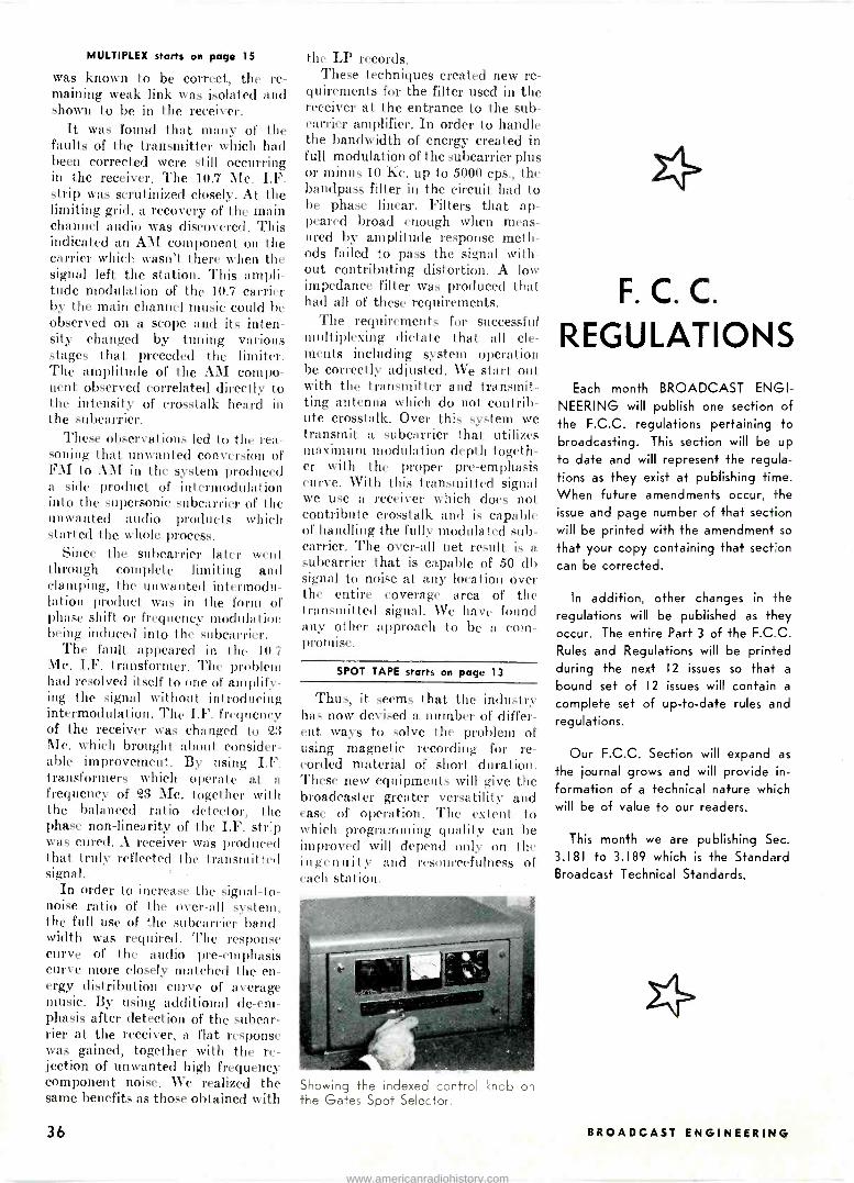
MULTIPLEX starts on page 15
was known to be correct, the re- maining weak link was isolated and shown to be in the receiver.
It was found that many of the faults of the transmitter which had been corrected were still occurring in the receiver. The 10.7 Mc. I.F. strip was scrutinized closely. At the limiting grid, a recovery of the main channel audio was discovered. This indicated an AM component on the carrier which wasn't there when the signal left the station. This ampli- tude modulation of the 10.7 carrier by the main channel music could be observed on a scope and its inten- sity changed by tuning various stages that preceded the limiter. The amplitude of the AM compo- nent observed correlated directly to the intensity of crosstalk heard in the subcarrier.
These observations led to the rea- soning that unwanted conversion of FM to AM in the system produced a side product of intermodulation into the supersonic subcarrier of the unwanted audio products which started the whole process.
Since the subcarrier later wen t through complete limiting and clamping, the unwanted intermodu- lation product was in the form of phase shift or frequency modulation being induced into the subcarrier.
The fault appeared in the 10.7 Mc. I.F. transformer. The problem had resolved itself to one of amplify- ing the signal without introducing intermodulation. The I.F. frequency of the receiver was changed to 23 Mc. which brought about consider- able improvement. By using I.F. transformers which operate at a frequency of 23 Mc. together with the balanced ratio detector, the phase non -linearity of the I.F. str:p was cured. A receiver was produced that truly reflected the transmitted signal.
In order to increase the signal-to- noise ratio Of the over-all system, the full use of the subcarrier band- width was required. The response curve of the audio pre -emphasis curve more closely matched the en- ergy distribution curve of average music. By using additional de -em- phasis after detection of the subcar- rier at the receiver, a flat response was gained, together with the re- jection of unwanted high frequency component noise. We realized the same benefits as those obtained with
the LP records. These techniques created new re-
quirements for the filter used in the receiver at the entrance to the sub - carrier amplifier. In order to handle the bandwidth of energy created in full modulation of the subcarrier plus or minus 10 Kc. up to 5000 cps., the bandpass filter in the circuit had to be phase linear. Filters that ap- peared broad enough when meas- ured by amplitude response meth- ods failed to pass the signal with- out contributing distortion. A low impedance filter was produced that had all of these requirements.
The requirements for successful multiplexing dictate that all ele- ments including system operation be correctly adjusted. We start out with the transmitter and transmit- ting antenna which do not contrib- ute crosstalk. Over this system we transmit a subcarrier that utilizes maximum modulation depth togeth- er with the proper pre -emphasis curve. With this transmitted signal we use a receiver which does not contribute crosstalk and is capable of handling the fully modulated sub - carrier. The over-all net result is a subcarrier that is capable of 50 db signal to noise at any location over the entire coverage area of the transmitted signal. We have found any other approach to be a com- promise.
SPOT TAPE starts on page 13
Thus, it seems that the industry has now devised a number of differ- ent ways to solve the problem of using magnetic recording for re- corded material of short duration. These new equipments will give the broadcaster greater versatility and ease of operation. The extent to which programming quality can be improved will depend only on the ingenuity and resourcefulness of each station.
Showing the indexed control knob on the Gates Spot Selector.
F. C. C.
REGULATIONS Each month BROADCAST ENGI-
NEERING will publish one section of the F.C.C. regulations pertaining to broadcasting. This section will be up
to date and will represent the regula- tions as they exist at publishing time. When future amendments occur, the issue and page number of that section will be printed with the amendment so
that your copy containing that section can be corrected.
In addition, other changes in the regulations will be published as they occur. The entire Part 3 of the F.C.C. Rules and Regulations will be printed during the next 12 issues so that a
bound set of 12 issues will contain a
complete set of up-to-date rules and regulations.
Our F.C.C. Section will expand as
the journal grows and will provide in-
formation of a technical nature which will be of value to our readers.
This month we are publishing Sec.
3.181 to 3.189 which is the Standard Broadcast Technical Standards.
36 BROADCAST ENGINEERING
www.americanradiohistory.com
STANDARD BROADCAST TECHNICAL STANDARD S
§ 3.181. Introduction. (a) There are pre- sented herein the Technical Standards giv- ing interpretations and further considera- tion concerning the rules and regulations of the Federal Communications Commis- sion governing standard broadcast stations. While rules and regulations form the basis of good engineering practice, these stand- ards may go beyond the rules and regula- tions and set up engineering principles for consideration of various allocation prob- lems. These standards have been approved by the Commission and thus are considered as reflecting the opinion of the Commission in all matters involved.
(b) The Technical Standards set forth herein are those deemed necessary for the construction and operation of standard broadcast stations to meet the require- ments of technical regulations and for op- eration in public interest along technical lines not specifically enunciated in the regulations. These standards are based on the best engineering data available from evidence supplied in formal and informal hearings and extensive surveys conducted in the field by the Commission's personnel. Numerous informal conferences have been held with radio engineers, manufacturers of radio equipment and others for the guidance of the Commission in the formu- lation of these standards.
(c) These standards are complete in them- selves and supersede any previous an- nouncements or policies which may have been enunciated by the Commission on engineering matters concerning standard broadcast stations.
(d) While these standards provide for flexibility and set forth the conditions under which they are applicable, it is not expected that material deviation therefrom as to fundamental principles will be recog- nized unless full information is submitted as to the reasonableness of such departure and the need therefor.
(e) These standards will necessarily change as progress is made in the art, and accordingly it will be necessary to make revisions from time to time. The Commis- sion will accumulate and analyze engineer- ing data available as to the progress of the art so that its standards may be kept cur- rent with the developments.
§ 3.182 Engineering standards of alloca- tion. (a) Sections 3.21 to 3.34, inclusive, govern allocation of facilities in the stand- ard broadcast band of 535 to 1605 kc. Sec- tion 3.21 establishes three classes of chan- nels in this band, namely, clear channels for the use of high-powered stations, re- gional channels for the use of medium - powered stations, and local channels for the use of low -powered stations. The class- es and power of standard broadcast sta- tions which will be assigned to the various channels are set forth in § 3.22. The classification of the standard broadcast sta- tions are as follows:
(1) Class I stations are dominant stations operating on clear channels with powers of not less than 10 or more than 50 kw. These stations are designed to render primary and secondary service over an extended area and at relatively long distances, hence have their primary service areas free from ob- jectionable interference from other stations on the same and adjacent channels and sec- ondary service areas free from objection- able interference from stations on the same channels. (The secondary service area of a Class I station is not protected from ad- jacent channel interference. However, if it is desired to make a determination of tie area in which adjacent channel ground - wave interference (10 kc removed) to sky - wave service exists, it may be considered as the area where the ratio cf the desired 50% skywave of the Class I station to the undesired groundwave of a station 10 kc removed is 1 to 4.) From an engineering point of view, Class I stations may be divided into two groups and, hereafter, for the purpose of convenience, the two groups of Class I stations will be termed Class I -A or I -B in accordance with the assignment to channels allocated by § 3.25 (a) or (b).
3.182 (i) The Class I stations in Group 1-A
are those assigned to the channels allocated by section 3.25 (a), on which except to the extent therein provided, duplicate night- time operation is not permitted, that is, no other station is permitted to operate on a channel with a Class I station of this group within the limits of the United States (the Class II stations assigned the channels op- erate limited time or daytime only), and during daytime the Class I station is pro- tected to the 100 uv/m groundwave con- tour. Protection is given this class of sta- tion to the 500 uv/m groundwave contour from adjacent channel stations for both day and nighttime operations. The power of each Class I station shall not be less than 50 kw.
(ii) The Class I stations in group I -B are those assigned to the channels allocated by § 3.25 (b), on which duplicate operation is permitted, that is, other Class I or Class II stations operating unlimited time may be assigned to such channels. During night- time hours of operation a Class I station of this group is protected to the 500 uv/m 50 percent sky wave contour and during daytime hours of operation to the 100 uv/m ground wave contour from stations on the same channel. Protection is given to the 500 uv/m groundwave contour from stations on adjacent channels for both day and nighttime operation. The operating powers of Class I stations on these fre- quencies shall be not less than 10 kw nor more than 50 kw.
(2) Class II stations are secondary sta- tions which operate on clear channels with powers not less than 0.25 kw. or more than 50 kw. These stations are required to use a directional antenna or other means to avoid causing interference within the nor- mally protected service areas of Class I sta- tions or other Class II stations. These sta- tions normally render primary service only, the area of which depends on the geo- graphical location, power, and frequency. This may be relatively large but is limited by and subject to such interference as may be received from Class I stations. However, it is recommended that Class II stations be so located that the interference received from other stations will not limit the serv- ice area to greater than the 2500 uv/m ground wave contour nighttime and 500 uv/m groundwave contour daytime, which are the values for the mutual protection of this class of stations with other stations of the same class.
(3) Class III stations operate on regional channels and normally render primary service to the larger cities and the rural area contiguous thereto, and are subdiv- ided into two classes:
(i) Class III -A stations which operate with powers not less than i kw or more than 5 kw are normally protected to the 2500 uv/m groundwave contour nighttime and the 500 uv/m groundwave contour daytime.
(ii) Class III -B stations which operate with powers not less than 0.5 kw, or more than 1 kw nighttime and 5 kw daytime are normally protected to the 4000 uv/m groundwave contour nighttime and 500 uv/m groundwave contour daytime.
(4) Class IV stations operate on local channels normally rendering primary serv- ice only to a city or town and the suburban or rural areas contiguous thereto with power not less than 100 watts, nor more than 250 watts nighttime and 1 kilowatt daytime. The stations are normally pro- tected lo the 0.5 my/m groundwave con- tour daytime. On local channels the sepa- ration required for the daytime protection shall also determine the nightime separa- tion. Where directional antennas are em- ployed in the daytime by Class IV stations utilizing power in excess of 250 watts, the separations required shall in no case be less than those necessary to afford protec- tion, assuming nondirectional operation with 100 watts or 250 watts, whichever is the nighttime power of the station. In no case will 250 watts nighttime operation be authorized to a station unable to operate omnidirectionally at 250 watts in the day- time. The actual nighttime limitation will be calculated.
10 percent skywave
Inner Outer signal Zone radius radius (mv/m)
A 00 0.10 B 00 80 .12 C 80 100 .14 D 100 250 .16 E 250 350 .14 F 350 450 .12 G 450 500 .10
Where the power of the interfering station is not 250 watts, the 10% skywave signal should be adjusted by the square root of the ratio of the power to 250 watts.
Where the power of the interfering sta- tion is not 250 watts, the 10% skywave signal should be adjusted by the square root of the ratio of the power to 250 watts.
(b) The class of any station is determined by the channel assignment, the power, and the field intensity contour to which it ren- ders service free of interference from other stations as determined by these standards. No station will be permitted to change to a class normally protected to a contour of less intensity than the contour to which the station actually renders interference -free service. Any Station of a class normally protected to a contour of less intensity than that to which the station actually renders interference -free service, will be automatically reclassified according to the class normally protected, the minimum con- sistent with its power and channel assign- ment. Likewise, any station to which the interference is reduced so that service is rendered to a contour normally protected for a higher class will be automatically changed to that class if consistent with its power and channel assignment.
(c) When it is shown that primary serv- ice is rendered by any station, beyond the normally protected contour, and when pri- mary service to approximately 90 per cent of the population (population served with adequate signal) of the area between the normally protected contour and the contour to which such station actually serves, is not supplied by any other station or stations carrying the same general program service, the contour to which protection may be afforded in such cases will be determined from the individual merits of the case un- der consideration.
(d) When a station is already limited by interference from othe- stations to a con- tour of higher value than that normally protected for its class, this contour shall be the established standard for such station with respect to interference from all other stations.
(e) The several classes of broadcast sta- tions have in general three service areas; namely, primary, secondary, and intermit- tent service areas. (See § 3.11 for the defi- nitions of primary, secondary, and inter- mittent service areas.) Class I stations ren- der service to all three service areas. Class II stations render service to a primary area but the secondary and intermittent service areas may be materially limited or de- stroyed due to interference from other sta- tions depending on the station assignments involved. Class III and IV stations usually have only primary service areas as inter- ference from other stations generally pre- vents any secondary service and may limit the intermittent service area. However, complete intermittent service may be ob- tained in many cases depending on the sta- tion assignments involved.
(f) The signals necessary to render pri- mary service to different types of service areas are as follows:
Field Intensity Area: groundwavel
City business or fac- tory areas 10 to 50 my/m.
City residentials areas 2 to 10 my/m. Rural-all areas during
winter or northern areas during summer. 0.1 to 0.5 my/m.
Rural - southern areas during summer 0.25 to 1.0 my/m.
See section 3.184 for curves showing distances to various groundwave field in- tensity contours for different frequency and ground conductivities and section 3.183. All these values are based on an absence of objectionable fading, either in changing in -
May. 1959 37
www.americanradiohistory.com

tensity or selective fading, the usual noise level in the areas, and an absence of limit- ing interference from other broadcast sta- tions. The values apply both day and night but generally fading or interference from other stations limits the primary service at night in all rural areas to higher values of field intensity than the values given. The Commission will authorize a directive an- tenna for a Class IV station for daytime operation only with power in excess of 250 watts. In computing the degrees of protec- tion which such antenna will afford, the radiation produced by this antenna shall be assumed to be no less, in any direction, than that which would result from non - directional operation, utilizing a single ele- ment of the directional array, with 100 watts or 250 watts, whichever is the night- time power of the station.
Note: Standards have not been established for interference from atmospherics or man- made electric noise as no uniform method of measuring noise or static has been estab- lished. In any individual case objectionable interference from any source, except other broadcast signals. may be determined by comparing the actual noise interference re- produced during reception of a desired broadcast signal to the degree of interfer- ence that would be caused by another broadcast signal within 20 cycles of the de- sired signal and having a carrier ratio of 20 to 1 with both signals modulated 100 per cent on peaks of usual programs. Stand- ards of noise measurements and interfer- ence ratio for noise are now being studied.
(g) In determining the population of the primary service area, it may be considered that the following signals are satisfactory to overcome man-made noise in towns of the population given.
Field intensity Population: groundwave
Up to 2,500 0 5 mv/m 2,500 to 10,000 2 0 mv/m 10,000 and up Values given in
paragraph (f) of this section These values are subject to wide variations in individual areas and especial attention must be given to interference from other stations. The values are not considered sat- isfactory in any case for service to the city in which the main studio of the station is located. The values in paragraph (f) of this section shall apply except as individual consideration may determine.
(h) All classes of broadcast stations have primary service areas subject to limitation by fading and noise, and interference from other stations to the contours set out for each class of station.
(i) Secondary service is delivered in the areas where the skywave for 50 per cent or more of the time has a field intensity of 500 uv/m or greater. (The secondary serv- ice area of a Class 1-A station should be considered as having this limit only for de- termination of service in comparison with other stations.) It is not considered that satisfactory secondary service can be ren- dered to cities unless the skywave ap- proaches in value the ground wave re- quired for primary service. The secondary service is necessarily subject to some in- terference and extensive fading whereas the primary service area of a station is subject to no objectionable interference or fading. Class I stations only are assigned on the basis of rendering secondary service.
Note: Standards have not been estab- lished for objectionable fading as such standards would necessarily depend on the receiver characteristics which have been changed considerably in this regard during the last several years. Selective fading causing audio distortion and the signal fading below the noise level are the ob- jectionable characteristics of fading on modern design receivers. The AVC circuits in the better designed modern receivers in general maintain the audio output suffi- ciently constant to be satisfactory during most fading.
(j) The intermittent service is rendered by the groundwave and begins at the outer boundary of the primary service area and extends to the value of signal where it may be considered as having no further service value. This may be down to only a few microvolts in certain areas and up to sev- eral millivolts in other areas of high noise level, interference from other stations, or objectionable fading at night. The inter- mittent service area may vary widely from day to night and generally varies from time to time as the name implies. Only Class I
stations are assigned for protection from interference from other stations into the intermittent service area.
(k) Section 3.23 provides that the several classes of broadcast stations may be li- censed to operate unlimited time, limited time ,daytime, sharing time, and specified hours, with full explanation given in the section.
(1) Section 3.24 sets out the general re- quirements for obtaining an increase in facilities of a licensed station and for a new station. Section 3.24 (b) concerns the matter of interference that may be caused by a new assignment or increase in facili- ties of an existing assignment.
(m) [Reserved (n) fReserved.1 (o) Objectionable interference from
another broadcast station is the degree of interference produced when, at a specified field intensity contour with respect to the desired station, the field intensity of an un- desired station (or the root -sum -square value of field intensities of two or more stations on the same frequency) exceeds for ten (10) per cent or more of the time the values set forth in these standards. (The secondary service area of a Class 1-A sta- tion should be considered as having this limit only for determination of service in comparison with other stations.)
(1) With respect to the root -sum -square values of interfering field intensities re- ferred to herein, except in the case of Class IV stations on local channels, calcu- lation is accomplished by considering the signals in order of decreasing magnitude, adding the squares of the values and ex- tracting the square root of the sum ex- cluding those signals which are less than 50% of the RSS value of the higher signals already included.
(2) The RSS value will not be considered to be increased when a new interfering signal is added which is less than 50% of the RSS value of the interference from existing stations, and which at the same time is not greater than the smallest signal included in the RSS value of interference from existing stations.
(3) It is recognized that application of the above "50% exclusion" method of cal- culating the RSS interference may result in some cases in anomalies wherein the ad- dition of a new interfering signal or the increase in value of an existing interfering signal will cause the exclusion of a previ- ously included signal and may cause a de- crease in the calculated RSS value of inter- ference. In order to provide the Commission with more realistic information regarding gains and losses in service (as a basis for determination of the relative merits of a proposed operation) the following alternate method for calculating the proposed RSS values of interference will be employed wherever applicable.
(4) In the cases where it is proposed to add a new interfering signal which is not less than 50% of the RSS value of in- terference from existing stations or which is greater than the smallest signal already included to obtain this RSS value, the RSS limitation after addition of the new signal shall be calculated without excluding any signal previously included. Similarly, in cases where it is proposed to increase the value of one of the existing interfering signals which has been included in the RSS value, the RSS limitation after the increase shall be calculated without excluding the interference from any source previously included.
(5) If the new or increased signal pro- posed in such cases is ultimately authorized. the RSS values of interference to other stations affected will thereafter be calcu- lated by the "50% exclusion" method with- out regard to this alternate method of cal- culation.
(6) Examples of RSS interference calcu- lations:
(i) Existing interferences: Station No. 1-1.0 my/m. Station No. 2-0.60 mv/m. Station No. 3-0.59 my/m. Station No. 4-0.58 mv/m. The RSS value from Nos. 1, 2 and 3 is
1.31 my/m; therefore interference from No. 4 is excluded for it is less than 50% of 1.31 my/m.
(ii) Station A receives interference from: Station No. 1-1.0 my/m. Station No. 2-0.60 my/m. Station No. 3-0.59 my/m. It is proposed to add a new limitation -
0.68 my/m. This is more than 50% of 1.31 my/m, the RSS value of Nos. 1, 2 and 3. The RSS value of Station No. 1 and of the proposed station would be 1.21 mv/m which is more than twice as large as the limitation from Station No. 2 or No. 3. However, under the above provision the new signal and the three existing inter- ferences are nevertheless calculated for purposes of comparative studies, resulting in an RSS value of 1.47 my/m. However, if the proposed station is ultimately au- thorized only No. 1 and the new signal are included in all subsequent calculations for the reason that Nos. 2 and 3 are less than 50% of 1.21 my/m, the RSS value of the new signal and No. 1. (iii) Station A receives interference from: Station No. 1-1.0 my/m. Station No. 2-0.60 my/m. Station No. 3-0.59 my/m.
No. 1 proposes to increase the limitation it imposes on Station A to 1.21 my/m. Although the limitations from stations Nos. 2 and 3 are less than 50% of the 1.21 mv/m limitation, under the above provision they are nevertheless included for comparative studies, and the RSS limitation is calcu- lated to be 1.47 my/m. However, if the in- crease proposed by Station No. 1 is author- ized. the RSS value then calculated is 1.21 mv/m because Stations Nos. 2 and 3 are ex- cluded in view of the fact that the limita- tions they impose are less than 50% of 1.21 my/m.
(p) Objectionable interference from a station on the same channel shall be con- sidered to exist to a station when, at the field intensity contour specified in para- graph (y) of this section with respect to the class to which the station belongs, the field intensity of an interfering station (or the root -sum -square value of the field intensi- ties of two or more interfering stations) operating on the same channel, exceeds for ten (10) per cent or more of the time the value of the permissible interfering signal set forth opposite such class in paragraph (v) of this section.
(q) Objectionable interference from a station on an adjacent channel shall be considered to exist to a station when, at the normally protected contour of a de- sired station, the field intensity of the ground wave of an undesired station operat- ing on an adjacent channel (or the root - sum -square value of the field intensities of two or more such undesired stations operat- ing on the same adjacent channel) exceeds a value specified in paragraph (w) of this section.
(r) For the purpose of estimating the coverage and the interfering effects of stations in the absence of field intensity measurements, use shall be made of Fig- ure 8 of § 3.190 which describes the esti- mated effective field for one kilowatt power input of simple vertical omnidi- rectional antennas of various heights with ground systems of at least 120 one -quarter wavelength radials. Certain approximations, based on the curve or other appropriate theory, may be made when other than such antennas and ground systems are em- ployed shall not be less than given in the following: Class of station: Effective field
1 225 mv/m II and III 175 mv/m IV 150 mv/m
In case a directional antenna is employed, the interfering signal of a broadcasting sta- tion will vary in different directions, being greater than the above values in certain directions and less in others, depending upon the design and adjustment of the di- rectional antenna system. To determine the interference in any direction the measured or calculated radiated field (unabsorbed field intensity at 1 mile from the array) must be used in conjunction with the ap- propriate propagation curves. (See § 3.185 for further discussion and solution of a typical directional antenna case.)
(s) The existence or absence of objec- tionable groundwave interference from stations on the same or adjacent channels shall be determined by actual measurements made according to the method hereinafter described, or, in the absence of such meas- urements, by reference to the propagation curves of § 3.184. The existence or absence
38 BROADCAST ENGINEERfNG
www.americanradiohistory.com

Frequency to- separation of desired to un- Undesired Undesired
desired signals- ground- 10 percent wave skywave
of objectionable interference due to sky - wave propagation shall be determined by reference to the appropriate propagation curves in Figure 1 or Figure 2 of § 3.190.
(t) In computing the fifty (50) per cent skywave field intensity values and the ten (10) per cent skywave field intensity values of a station on a clear channel, use shall be made of the appropriate graph set forth in Figure 1 of § 3.190 entitled "Average Ekywave Field Intensity" (corresponding to the second hour after sunset at the record- ing station). These graphs are drawn for a radiated field of 100 my/m at 1 mile in the horizontal plane from a 0.311 wavelength antenna. In computing the ten (10) per cent skywave field intensity of a regional chan- nel station, use shall be made of the ap- propriate curve in Figure 2 of § 3.190 en- titled "10 per cent Skywave Signal Range." This graph is drawn for a radiated field of 100 my/m at 1 mile at the vertical angle pertinent to transmission by one reflection. This curve supersedes the ten (10) per cent skywave curve of Figure 1 of § 3.190, only for regional and local channels at the present time. Adoption of revised skywave curves for use on clear channels will await the outcome of the Clear Channel Hearing (Docket No. 6741).
(u) The distance to any specified ground - wave field intensity contour for any fre- quency may be determined from the ap- propriate curves in § 3.184 entitled "Ground Wave Field Intensity vs. Distance."
(v) Protected service contours and per- missible interference signals for broadcast stations are as follows:
Class of Class of station channel Permissible power
used
I -A Clear.... 50 kw
I-13 Clear.... 10 kw. to 50 kw
II .Clear.... 025 kw. to 50 III -A Regional. 1 kw. to 5 kw III -B.... Regional. 0.5 to 1 kw. night
and 5 kw. day IV Local.... 0.1 kw. to 0.25 kw.
with antenna systems side by side or other- wise in proximity without any indications of interference if the interference is de- fined only in terms of permissible ratios listed in this paragraph. As a practical mat- ter, serious interference problems may arise when two or more stations with the same general service area are operated on chan- nels 10, 20 and 30 kilocycles apart.
(x) Two stations, one with a frequency twice that of the other, should not be as- signed in the same groundwave service area unless special precautions are taken to avoid interference from the second har- monic of the lower frequency. In selecting a frequency, consideration should be given to the fact that occasionally the frequency assignment of two stations in the same area may bear such a relation to the interme- diate frequency of some broadcast receivers as to cause so-called "image" interference. However, since this can usually be recti- fied by readjustment of the intermediate frequency of such receivers, the Commis- sion in general will not take this kind of interference into consideration in alloca- tion problems.
(y) Two stations operating with syn- chronized carriers and carrying the identi- cal program will have their groundwave service subject to some distortion in areas where the signals from the two stations are of comparable intensity. For the purpose of estimating coverage of such stations, areas in which the signal ratio is between 1 to 2 and 2 to 1 will not be considered as having satisfactory service.
Signal intensity contour of area protected from objectionable
interference' Day3 Night
Permissible interfering signal on same chan- nel2
Day3 Night
SC 100 uv/m. Not duplicated 'i uv/m.... Not dupli- AC 500 uv/m. cated. SC 100 uv/m. 500 uv/in 5 uv/m... . 25 uv/m. AC 500 uv/m. (50% skywave). 500 uv/m 2500 uv/nr5 (groundwave) 500 uv/n) 2500 uv/m (groundwave). 500 uv/m 4000 uv/nt (groundwave). 500 uv/m Not prescribede
25 uv/m. .. 125 uv/m. 25 uv/m... 125 uv/m. 25 uv/m... 200 uv/m.
25 uv/m... Not pre- scribed.,
' When It is shown that primary service is rendered by any of the above classes of stations, be- yond the normally protected contour, and when primary service to approximately 90 percent of the population (population served with adequate signal) of the area between the normally protected contour and the contour to which such station actually serves, is not supplied by any other station or stations, the contour to which protection may be afforded in such cases will be determined from the individual merits of the case under consideration. When a station is already limited by inter- ference from other stations to a contour of higher value than that normally protected for its class, this contour shall be the established standard for such station with respect to interference from all other stations.
2 For adjacent channels see paragraph (w) of this section. 3 Ground wave. 4 Skywave field intensity for 10 percent or more of the time. e These values are with respect to interference from all stations except Class I -Il, which stations
may cause interference to a field intensity contour of higher value. However, it is recommended that Class II stations be so located that the interference received from Class I -B stations will not exceed these values. If the Class II stations are limited by Class 1-B stations to higher values. then such values shall he the established standard with respect to protection from all other stations.
6 See paragraph (a) (4) of this section. SC-Same channel. AC=Adjacent channel. NOTE: See, however, Sec. 3.25 with reference to the frequency 770 kilocycles.
(w) The following ratios are to be used for determining the minimum ratio of the field intensity of a desired to an undesired signal for interference free service. In the case of a desired groundwave signal inter- fered with by two or more skywave signals on the same frequency, the RSS value of the latter is used.
Desired 50 Desired groundwave percent
skywave to unde- sired 10 percent skywave
0 kc 20 :1 20:1 20:1 10 kc 1:1 1:5 (1) 20 kc 1:30 .... ...
'The secondary service area of a Class I sta- tion is not protected from adjacent channel in- terference. However, if it is desired to make a determination of the area in which adjacent channel groundwave interference (10 kc. re- moved) to skywave service exists, it may be considered as the area where the ratio of the desired 50 percent skvwave of the Class I sta- tion to the undesired groundwave of a station 10 kc. removed is 1 to 4.
From the above, it is apparent that in many cases stations operating on channels 10 and 20 kilocycles apart may be operated
Note: Two stations are considered to be operated synchronously when the carriers are maintained within one -fifth of a cycle per second of each other and they trans- mit identical programs.
§ 3.183 Groundwave signals. (a) Interfer- ence that may be caused by a proposed assignment or an existing assignment during day time should be determined, when possible, by measurements on the fre- quency involved or on another frequency over the same terrain and by means of the curves in § 3.184 entitled "Ground Wave Field Intensity versus Distance."
(b) In determining interference based upon field intensity measurements, it is necessary to do the following: First, estab- lish the outer boundary of the protected service area of the desired station in the direction of the station that may cause in- terference to it. Second, at this boundary, measure the interfering signal from the un- desired station. The ratio of the desired to the undesired signal given in § 3.182 (w) should be applied to the measured signals and if the required ratio is observed, no objectionable interference is foreseen. When measurements of both the desired and undesired stations are made in one area to determine the point where object-
tionable interference from groundwave sig- nals occur or to establish other pertinent contours, several measurements of each sta- tion shall be made within a few miles of this point or contour. The effective field of the antennas in the pertinent directions of the stations must be established and all measurements must be made in accord- ance with § 3.186.
(c) In all cases where measurements taken in accordance with the requirements are not available, the groundwave intensity must be determined by means of the perti- nent map of ground conductivity and the groundwave curves of field intensity versus distance. The conductivity of a given ter- rain may be determined by measurements of any broadcast signal traversing the ter- rain involved. Figures M3 and R3 of § 3.190 show the conductivity throughout the United States by general areas of reason- ably uniform conductivity. When it is clear that only one conductivity value is in- volved, Figure R3 of § 3.190, which is a
replica of Figure M3 and contained in these standards, may be used; in all other situa- tions Figure M3 must be employed. It is recognized that in areas of limited size or over a particular path, the conductivity may vary widely from the values given; there- fore, these maps are to be used only when accurate and acceptable measurements have not been made. (For determination of interference and service requiring a knowl- edge of ground conductivities in Canada and Mexico, Appendix H to the North American Regional Broadcasting Agree- ment, Washington, D. C., 1950, may be used. Where different conductivities appear in the maps of the several countries on differ- ent sides of the border not explained by geophysical cleavages, such cleavages are to be considered as real. A uniform ground conductivity of 10 millimhos per meter may be assumed for Cuba.
Note: Figure M3 which is incorporated in these Standards by reference, was derived by indicating ground conductivity values in the United States on the United States Albers equal area projection map (based on standard parallels 291/2° and 451/2'; North American datum; scale 1/2,500,000). Fig- ure M3, consisting of two sections, an east- ern and a western half, may be obtained from the Superintendent of Documents, Washington, D. C.
(d) Example of determining interference by the graphs in § 3.184:
It is desired to find whether objection- able interference exists between a 5 kw Class III station on 990 kc and a 1 kw Class III station on 1000 kc, the stations being seperated by 130 miles; both stations use nondirectional antennas having such height as to produce an effective field for 1 kw of 175 my/m. (See § 3.185 in case of use of directional antennas.) The conductiv- ity at each station and of the intervening terrain is determined as 6 mmhos/m. The protection to Class III stations during day- time is to the 500 uv/m contour. The dis- tance to the 500 uv/m groundwave con- tour of the 1 kw station is determined by the use of the appropriate curve in § 3.184, Graph 12. Since the curve is plotted for 10 my/m at a mile, to find the distance to the 500 uv/m contour of the 1 kw station, it is necessary to determine the distance to
(100X500 the 285 uv/m contour = 285).
175 From the appropriate curve, the estimated radius of the service area for the desired station is found to be 39.5 miles. Subtract- ing this distance from the distance between the two stations leaves 90.5 miles for the interfering signal to travel. From the above curve it is found that the signal from the 5 kw station at this distance would be 158 uv/m. Since a one to one ratio applies for stations separated by 10 kc, the undesired signal at that point can have a value up to 500 uv/m without objectionable interfer- ence. If the undesired signal had been found to be greater than 500 uv/m, then objectionable interference would exist. For other channel separations, the appropriate ratio of desired to undesired signal should be used.
(e) Where a signal traverses a path over which different conductivities exist,
May, 1959 39
www.americanradiohistory.com

the distance to a particular groundwave field intensity contour shall be determined by the use of the equivalent distance meth- od. Reasonably accurate results may be ex- pected in determining field intensities at a distance from the antenna by application of the equivalent distance method when the unattenuated field of the antenna, the various ground conductivities and the loca- tion of discontinuities are known. This method considers a wave to be propagated across a given conductivity according to the curve for a homogeneous earth of that conductivity. When the wave crosses from a region of one conductivity into a region of a second conductivity, the equivalent distance of the receiving point from the transmitter changes abruptly but the field intensity does not. From a point just inside the second region the transmitter appears to be at that distance where, on the curve for a homogeneous earth of the second con- ductivity, the field intensity equals the value that occurred just across the bound- ary in the first region. Thus the equivalent distance from the receiving point to the transmitter may be either greater or less than the actual distance. An imaginary transmitter is considered to exist at that equivalent distance. This technique is not intended to be used as a means of evaluat- ing unattenuated field or ground conductiv- ity by the analysis of measured data. The method to be employed for such determina- tions is set out in § 3.186.
(f) An example of the use of the equiv- alent distance method follows:
It is desired to determine the distance to the 0.5 mv/m and 0.025 mv/m contours of a station on a frequency of 1000 kc with an inverse distance field of 100 mv/m at one mile being radiated over a path having a conductivity of 10 mmhos/m for a dis- tance of 15 miles, 5 mmhos/m for the next 20 miles and 15 mmhos/m thereafte_ . By the use of the appropriate curves in § 3.184 -Graph 12, it is seen that at a distance of 15 miles on the curve for 10 mmhos/m the field is 3.45 my/m. The equivalent distance to this field intensity for a conductivity of 5 mmhos/m is 11 miles. Continuing on the propagation curve for the second conductiv- ity, the 0.5 mv/m contour is encountered at a distance of 27.9 miles from the imagi- nary transmitter. Since the imaginary trans- mitter was 4 miles nearer (15 - 11 miles) to the 0.5 mv/m contour, the distance from the contour to the actual transmitter is 31.9 miles (27.9+4 miles). The distance to the 0.025 mv/m contour is determined by continuing on the propagation curve for the second conductivity to a distance of 31 miles (11 + 20 miles), at which point the field is read to be 0.39 mv/m. At this point the conductivity changes to 15 mmhos/m and from the curve relating to that con- ductivity, the equivalent distance is deter- mined to be 58 miles -27 miles more dis- tant than would obtain had a conductivity of 5 mmhos/m prevailed. Using the curve representing the conductivity of 15 mmhos/ m the 0.025 mv/m contour is determined to be at an equivalent distance of 172 miles. Since the imaginary transmitter was con- sidered to be 4 miles closer at the first boundary and 27 miles farther at the sec- ond boundary, the net effect is to consider the imaginary transmitter 23 miles (27-4 miles) more distant than the actual trans - miter; thus the actual distance to the 0.025 mv/m contour is determined to be 149 miles (172 - 23 miles).
§ 3.184 Groundwave field intensity charts. (a) Graphs 1-19A show the computed values of groundwave field intensity as a function of the distance from the trans- mitting antenna. The groundwave field in- tensity is here considered to be that part of the vertical component of the electric field received on the ground which has not been reflected from the ionosphere nor the troposphere. These 20 charts were com- puted for 20 different frequencies, a dielec- tric constant of the ground equal to 15 for land and 80 for sea water (referred to air as unity) and for the ground conductivities (expressed in mmhos/m) given on the curves. The curves show the variation af the groundwave field intensity with dis- tance to be expected for transmission from a short vertical antenna at the surface of a
uniformly conducting spherical earth with the ground constants shown on the curves; the curves are for an antenna power and efficiency such that the inverse distance field is 100 mv/m at 1 mile. The curves are valid at distances large compared to the dimensions of the antenna for other than short vertical antennas.
(b) The inverse distance field (100 mv/m divided by the distance in miles) corre- sponds to the groundwave field intensity to be expected from an antenna with -the same radiation efficiency when it is located over a perfectly conducting earth. To de- termine the value of the groundwave field intensity corresponding to a value of in- verse distance field other than 100 mv/m at 1 mile, simply multiply the field in- tensity as given on these charts by the de- sired value of inverse distance field at 1 mile divided by 100; for example, to de- termine the groundwave field intensity for a station with an inverse distance field of 1700 mv/m at 1 mile, simply multiply the values given on the charts by 17. The value of the inverse distance field to be used for a particular antenna depends upon the power input to the antenna, the nature of the ground in the neighborhood of the antenna, and the geometry of the antenna. For methods of calculating the interrela- tions between these variables and the in- verse distance field, see "The Propagation of Radio Waves Over the Surface of the Earth and in the Upper Atmosphere," Part I, by Mr. K. A. Nort;n, Proc. IR. E., Vol. 25, September 1937, pp. 1203-1236.
(c) At sufficiently short distances (say less than 35 miles), such that the curva- ture of the earth does not introduce an ad- ditional attenuation of the waves, the graphs were computed by means of the plane earth formulas given in the paper, "The Propagation of Radio Waves Over the Surface of the Earth and in the Upper At- mosphere," Part I, by Mr. K. A. Norton, Proc. I. R. E., Vol. 24, October 1936, pp. 1367-1387. At larger distances the addi- tional attenuation of the waves which is introduced by the effect of the curvature of the earth was introduced by the meth- ods outlined in the papers, "The Diffraction of Electromagnetic Waves from an Electri- cal Point Source round a Finitely Conduct- ing Sphere, with Applications to Radiotele- graphy and the Theory of the Rainbow," by Balth van der Pol and H. Bremmer, Part I, Phil. Mag., Vol. 24, p. 141, July 1937, Part II, Phil. Mag., Vol. 24, p. 825, Suppl., November 1937, "Ergebrisse einer Theorie uber die Fortpflanzung elektro- magnetischer Wellen uber eine Kugel end- licher Leitfahigkeit," by Balth van der Pol and H. Bremmer, Hochfrequenztechnik and Elektroakustik, Band 51, Heft 6, June 1938, "Further Note on the Propagation of Radio Waves over a Finitely Conducting Spherical Earth," by Balth van der Pol and H. Brem- mer, Phil. Mag., Vol. 27, p. 261, March 1939. In order to allow for the refraction of the radio waves in the lower atmosphere due to the variation of the dielectric constant of the air with height above the earth, a radius of the earth equal to 4/3 the actual radius was used in the computations for the effect of the earth's curvature in the manner suggested by C. R. Burrows, "Radio Propogation over Spherical Earth," Proc. I. R. E., May 1935; i.e., the distance corresponding to a given value of attenua- tion due to the curvature of the earth in the absence of air refraction was multiplied by the factor (4/3) % - 1.21. The amount of this refraction varies from day to day and from season to season, depending on the air mass conditions in the lower at- mosphere. If k denotes the ratio between the equivalent radius of the earth and the true radius, the following table gives the values of k for several typical air masses encountered in the United States. It is clear from this table that the use of
Air mass type k
Summer Winter Tropical Gulf-Te 1.53 1.43 Polar Continental-Ye 1.31 1.25 Superior-S 1.25 1.25 Average 1.33
the average value of k - 4/3 is justified in obtaining a single correction for the systematic effects of atmospheric refrac- tion.
(d) Provided the value of the dielectric constant is near 15, the curves of Graphs 1-19A may be compared with experimen- tal data to determine the appropriate values of the ground conductivity and of the in- verse distance field intensity at 1 mile. This is accomplished simply by plotting the measured fields on transparent log -log graph paper similar to that used for Graphs 1-19A and superimposing this chart over the graph corresponding to the frequency involved. The log -log graph sheet is then shifted vertically until the best fit is ob- tained with one of the curves on the graph; the intersection of the inverse distance line on the graph with the 1 -mile abscissa on the chart determines the inverse distance field intensity at 1 mile. For other values of dielectric constant, the following pro- cedure may be used for a determination of the dielectric constant of the ground, conductivity of the ground and the inverse distance field intensity at 1 mile. Graph 20 gives the relative values of groundwave field intensity over a plane earth as a func- tion of the numerical distance p and phase angle b. On graph paper with coordinates similar to those of Graph 20, plot the meas- ured values of field intensity as ordinates versus the corresponding distances from the antenna expressed in miles as abscissae. The data should be plotted only for dis- tances greater than one wavelength (or, when this is greater, five times the verti- cal height of the antenna in the case of a single element, i.e., nondirectional an- tenna or 10 times the spacing between the elements of a directional antenna) and for distances less than 50/f OA mc) miles (ie., 50 miles at 1 mc). Then, using a light box, place the sheet with the data plotted on it over the sheet with the curves of Graph 20 and shift the data sheet vertically and horizontally (making sure that the vertical lines on both sheets are parallel) until the best fit with the data is obtained with one of the curves on Graph 20. When the two sheets are properly lined up, the value of the field intensity corresponding to the intersection of the inverse distance line of Graph 20 with the 1 mile abscissa on the data sheet is the inverse distance field in- tensity at 1 mile, and the values of the numerical distance at 1 mile, pi, and of b are also determined. Knowing the values of b and pi, (the numerical distance at 1 mile), we may substitute in the following approximate formulas to determine the ap- propriate values of the ground conductivity and dielectric constant.
z' r- (R7a),.cos 6 (1)
(R/a),=Number of wavelengths in 1 mile.
o. m . . (2) 17.9731 v...,. ,,.=Conductivity of the ground expressed in elec
tromagnetic units. f.,.=frequency expressed in megacycles.
e'z tan h-1 (3) e-dielectric constant of the ground referred to air
as unity. First solve for x by substituting the known values of pl, (R/w*)i, and cos b in equation (1). Equation (2) may then be solved for o and equation (3) for e). At distances greater than 50/f ( mc) miles the curves of Graph 20 do not give the correct rela- tive values of field intensity since the curvature of the earth weakens the field more rapidly than these plane earth curves would indicate. Thus, no attempt should be made to fit experimental data to these curves at the larger distances. *Wave Length.
(e) At sufficiently short distances (say less than 35 miles at broadcast frequen- cies), such that the curvature of the earth does not introduce an additional attenua- tion of the waves, the curves of Graph 20 may be used for determining the ground wave field intensity for transmitting and receiving antennas at the surface of the earth for any radiated power, frequency, or set of ground constants in the following manner: First, lay off the straight inverse distance line corresponding to the power radiated on transparent log -log graph paper similar to that of Graph 20, labeling the
40 BROADCAST ENGINEERING
www.americanradiohistory.com

ordinates of the chart in terms of field in- tensity, and the abscissae in terms of dis- tance. Next, by means of the formulas given on Graph 20, calculate the value of the numerical distance, p, at 1 mile, and the value of b. Then superimpose the log - log chart over Graph 20, shifting it verti- cally until the inverse distance lines on both charts coincide and shifting it hori- zontally until the numerical distance at 1
mile on Graph 20 coincides with 1 mile on the log -log graph paper. The curve of Graph 20 corresponding to the calculated value of b is then traced on the log -log graph paper giving the field intensity versus distance in miles.
§ 3.185 Computation of interfering signal from a directional antenna. (a) In case of an antenna directional in the horizontal plane, the groundwave interference can be readily computed from the calculated hori- zontal pattern by determining the vectors toward the service area of the station to be protected and apply these values to the groundwave curves set out in § 3.183.
(b) For signals from stations operating on clear channels, in case of determining skywave interference from an antenna with a vertical pattern different from that on which Figure 1 of § 3.190 is predicted (the basis of the night mileage separation tables), it is necessary to compare the ap- propriate vectors in the vertical plane.
(c) The skywave curves entitled "Aver- age Skywave Field Intensity" (correspond- ing to the second hour after sunset at the recording station) as shown in Figure 1 of § 3.190 are based on antenna systems having height of 0.311 wave length (112") and producing a vertical pattern as shown in Figure 5 of § 3.190. A nondirectional an- tenna system, as well as a directional an- tenna system having vertical patterns other than essentially the same as shown, must be converted to the pattern of a 0.311 wave length antenna having the same field in- tensity at the critical angle as does the pattern of the antenna involved.
(d) Example of the use of skywave curves: Figure 6 of § 3.190 is a graph entitled "Variation With Distance of Two Impor- tant Parameters in the Theory of Sky Wave Propagation." The curve for o showing the angle above the horizon at which radiation occurs plotted against distance, must be used for this purpose. For instance, assum- ing the station with which interference may be expected is located at a distance of 450 miles from a proposed station, the criti- cal angle of radiation as determined from this curve is approximately 15°. Therefore, if the vertical pattern of the proposed sta- tion in the direction of the other station is such that at 15° above the horizon the radiation is 1.3 times that from an an- tenna having a vertical pattern as shown in Figure 5 of § 3.190 and producing the same field intensity at 1 mile in the hori- zontal plane, the interfering signal would be 1.3 times that determined from Figure 1 of § 3.190 for an antenna having the same field intensity in the horizontal plane. That is, if the field intensity in the horizontal plane of the proposed station is 124 mv/m the interfering field intensity exceeded 10 per cent of the time at the other station would be
124 140 X 1.30 X - or 225 uv/m
100 and would cause interference to the 4.5 mv/m ground wave contour of the exist- ing station.
(e) For signals from stations on regional and local channels, in computing the 10% skywave (interference) field intensity values of Class III and Class IV stations, Fig. 2 of § 3.190 is to be used in place of Figure 1 of § 3.190. (Certain simplifying assumptions may be made in the case of Class IV stations on local channels: See note to § 3.182 (a) (4). Since Figure 2 of § 3.190 is predicted upon a radiated field of 100 mv/m at one mile in the pertinent direction, no comparison with the vertical pattern of a 0.311 wavelength antenna is to be made. Instead the appropriate radiated field in the vertical plane corresponding to the distance to the receiving station, divided by 10, is multiplied into the value of 10%
skywave field intensity determined from Figure 2 of § 3.190. There are two new factors to be considered, however, namely the variation of received field with latitude of the path and the variation of pertinent vertical angle due to variations of iono- sphere height and ionosphere scattering.
(f) Figure 2 of § 3.190, "10% Skywave Signal Range Chart," shows the 10% sky - wave signal as a function of the latitude of the transmission path and the distance from a transmitting antenna with a radi- ated field of 100 mv/m at the pertinent angle for the distance. The latitude of the transmission path is defined as the geo- graphic latitude of the midpoint between the transmitter and the receiver. Latitude 35° should be used in case the midpoint of the path lies below 35° North and latitude 50° should be used in case the midpoint of the path lies above 50° North.
(g) Figure 6-A of § 3.190, entitled "Angles of Departure vs. Transmission Range," is to be used in determining the angles in the vertical pattern of the antenna of an in- terfering station to be considered as perti- nent to transmission by one reflection. Cor- responding to any given distance, the curves 4 and 5 indicate the upper and lower angles within which the radiated field is to be considered. The maximum value off field intensity occurring between these angles will be used to determine the multiplying factor for the 10% skywave field intensity determined from Figure 2 of § 3.190. (Curves 2 and 3 are considered to represent the variation due to the varia- tion of the effective height of the E -layer while Curves 4 and 5 extend the range of pertinent angles to include a factor which allows for scattering. The dotted lines are included for information only.)
(h) In the case of non -directional vertical antennas, the vertical distribution of rela- tive fields for several heights, assuming sinusoidal distribution of current along the antenna, is shown in Figure 5 of § 3.190. In the case of directional antennas the ver- tical pattern in the great circle direction toward the point of reception in question must first be calculated. Then for the dis- tance to the points, the upper and lower pertinent angles are determined from Fig- ure 6-A of § 3.190. The ratio of the largest value of radiated field occurring between these angles, to 100 mv/m (for which Fig- ure 2 of § 3.190 is drawn) is then used as the multiplying factor for the value of the field read from the curves of Figure 2 of § 3.190. Note that while the accuracy of the curves is not as well established by meas- urements for distances less than 250 miles as for distances in excess of 250 miles, the curves represent the most accurate data available today. Pending accumulation of additional data to establish firm standards for skywave calculations in this range, the curves may be used. In cases where the radiation in the vertical plane, in the perti- nent azimuth, contains a large lobe at a higher angle than the pertinent angle for one reflection the method of calculating in- terference will not be restricted to that de- scribed above, but each such case will be censidered on the basis of the best knowl- edge available.
(i) Example, suppose it is desired to determine the amount of interference to a Class III station at Portland, Oregon, caused by another Class III station at Los Angeles, California, which is radiating a signal of 560 mv/m unattenuated at one mile in the great circle direction of Port- land, using a 0.5 wavelength antenna. The distance is 825 miles. From Figure 6-A of § 3.190 the upper and lower pertient angles are 7° and 3.5° and, from Figure 5 of § 3.190 the maximum radiation within these angles is 99% of the horizontal radiation or 554 mv/m at 1 mile. The latitude of the path is 39.8° N and from Figure 2 of § 3.190, the 10% skywave field at 825 miles is 0.050 mv/m for 100 mv/m radiated. Multiplying by (554/100) to adjust the value to the actual radiation gives 0.277 my/m. At 20 to 1 ratio the limitation to the Portland station is to the 5.5 mv/m contour.
(j) When the distance is large, more than one reflection may be involved and due consideration must be given each ap- propriate vector in the vertical pattern, as
well as the constants of the earth where re- flection takes place between the transmit- ting station and the service area to which interference may be caused.
§ 3.186 Field intensity measurements in allocation; establishment of effective field at one mile. (a) Section 3.45 provides that certain minimum field intensities are ac- ceptable in lieu of the required minimum physical vertical heights of the antennas proper. Also in other allocation problems, it is necessary to determine the effective field at 1 mile. The following requirements shall govern the taking and submission of data on the field intensity produced:
(1) Beginning as near to the antenna as possible without including the induction field and to provide for the fact that a broadcast antenna not being a point source of radiation (not less than one wavelength or 5 times the vertical height in the case of a single element, i.e., nondirectional an- tenna or 10 times the spacing between the elements of a directional antenna), meas- urements shall be made on eight or more radials, at intervals of approximately one - tenth mile up to 2 miles from the antenna, at intervals of approximately one-half mile from 2 miles to 6 miles from the antenna, at intervals of approximately 2 miles from 6 miles to 15 or 20 miles from the antenna, and a few additional measurements if needed at greater distances from the an- tenna. Where the antenna is rurally located and unobstructed measurements can be made, there shall be as many as 18 or 20 measurements on each radial. However, where the antenna is located in a city where unobstructed measurements are diffi- cult to make, measurements shall be made on each radial at as many unobstructed locations as possible, even though the in- tervals are considerably less than stated above, particularly within 2 miles of the antenna. In cases where it is not possible to obtain accurate measurements at the closer distances (even out to 5 or 6 miles due to the character of the intervening ter- rain), the measurements at greater distances should be made at closer intervals. (It is suggested that "wave tilt" measurements may be made to determine and compare locations for taking field intensity meas- urements, particularly to determine that there are no abrupt changes in ground con- ductivity or that reflected waves are not causing abnormal intensities.)
(2) The data required by subparagraph (1) of this paragraph should be plotted for each radial in accordance with either of the two methods set forth below:
(i) Using log -log coordinate paper, plot field intensities as ordinate and distance as abscissa.
(ii) Using semi -log coordinate paper, plot field intensity times distance as ordinate on the log scale and distance as abscissa on the linear scale.
(3) However, regardless of which of the methods in subparagraph (2) of this para- graph is employed, the proper curve to be drawn through the points plotted shall be determined by comparison with the curves in § 3.184 as follows: Place the sheet on which the actual points have been plotted over the appropriate Graph in § 3.184, hold to the light if necessary and adjust until the curve most closely matching the points is found. This curve should then be drawn on the sheet on which the points were plotted, together with the inverse distance curve corresponding to that curve. The field at 1 mile for the radial concerned shall be the ordinate on the inverse dis- tance curve at 1 mile.
(4) When all radials have been analyzed in accordance with subparagraph (3) of this paragraph, a curve shall be plotted on polar coordinate paper from the fields obtained, which gives the inverse distance field pat- tern at 1 mile. The radius of a circle, the area of which is equal to the area bounded by this pattern, is the effective field. (See § 3.14.)
(5) While making the field intensity sur- vey, the output power of the station shall be maintained at the licensed power as determined by the direct method. To do this it is necesary to determine accurately the total antenna resistance (the resistance variation method, the substitution method
May, 1959 4I
www.americanradiohistory.com

or bridge method is acceptable) and to measure the antenna current by means of an ammeter of acceptable accuracy. (See § § 3.39 and 3.54.)
(b) Complete data taken in conjunction with the field intensity measurements shall be submitted to the Commission in affidavit form including the following:
(1) Tabulation by number of each point of measurement to agree with the map required in (2) below and the field intensity meter reading, the attenuation constant, the field intensity (E), the distance from the antenna (D) and the product of the field intensity and distance (ED) (if data for each radial are plotted on semi -logarithmic paper, see above) for each point of meas- urement.
(2) Map showing each point of meas- urement numbered to agree with tabula- tion required above.
(3) Description of method used to take field intensity measurements.
(4) The family of theoretical curves used in determining the curve for each radial properly identified by conductivity and di- electric constants.
(5) The curves drawn for each radial and the field intensity pattern.
(6) Antenna resistance measurement: (i) Antenna resistance at operating fre-
quency. (ii) Description of method employed. (iii) Tabulation of complete data. (iv) Curve showing antenna resistance
versus frequency. (7) Antenna current or currents main-
tained during field intensity measurements. (8) Description, accuracy, date, and by
whom each instrument was last calibrated. (9) Name, address and qualifications of
the engineer making the measurements. (10) Any other pertinent information. § 3.187 [Reserved.] § 3.188 Location of transmitters. (a) The
four primary objectives to be obtained in the selection of a site for a transmitter of a broadcast station are as follows:
(1) To serve adequately the center of population in which the studio is located and to give maximum coverage to adjacent areas.
(2) To cause and experience minimum interference to and from other stations.
(3) To present a minimum hazard to air navigation consistent with objectives (1) and (2).
(4) To fulfill certain other requirements given below.
(b) The site selected should meet the following conditions:
(1) A minimum field intensity of 25 to 50 my/m will be obtained over the busi- ness or factory areas of the city.
(2) A minimum field intensity of 5 to 10 mv/m will be obtained over the most distant residential section.
(3) The absorption of the signal is the minimum for any obtainable sites in the area. As a guide in this respect the absorp- tion of the signals from other stations in that area should be followed, as well as the results of tests on other sites.
(4) The population within the blanket contour does not exceed that specified by § 3.24 (g).
(c) In selecting a site in the center of a city it is usually necessary to place the radiating system on the top of a build- ing. This building should be large enough to permit the installation of a satisfactory ground and/or counterpoise system. Great care must be taken to avoid selecting a building surrounded by taller buildings or where any nearby building higher than the antenna is located in the direction which it is desired to serve. Such a building will tend to cast "radio shadows" which may materially reduce the coverage of the sta- tion in that direction. Irrespective of the height of surrounding buildings, the build- ing on which the antenna is located should not have height of approximately one - quarter wavelength. A study of antenna systems located on buildings tends to indi- cate that where the building is approxi- mately a quarter wavelength in height, the efficiency of radiation may be materially reduced.
(d) Particular attention must be given to avoiding cross -modulation. In this con-
nection, attention is invited to the fact that it has been found very unsatisfactory to locate broadcast stations so that high signal intensities occur in areas with overhead electric power or telephone distribution systems and sections where the wiring and plumbing are old or improperly installed. These areas are usually found in the older or poorer sections of a city. These condi- tions give rise to cross -modulation inter- ference due to the nonlinear conductivity characteristics of contacts between wiring, plumbing, or other conductors. This type of interference is independent of the se- lectivity characteristics of the receiver and normally can be eliminated only by correc- tion of the condition causing the interfer- ence. Cross -modulation tends to increase with frequency and in some areas it has been found impossible to eliminate all sources of cross -modulation, resulting in an unsatisfactory condition for both licensee and listeners. The Commission will not au- thorize, (1) new stations (2) increased facili- ties to existing stations, or (3) auxiliary transmitters, for use with other than the authorized antenna system of the main transmitter, located in such areas or utiliz- ing roof -top antennas, when the operating power would be in excess of 500 watts.
(e) If it is determined that a site should be selected removed from the city, there are several general conditions to be fol- lowed in determining the exact site. Three maps should be given consideration if
available: (1) Map of the density of population and
number of people by sections in the area. (See Bureau of Census series P -D and H -E available from Superintendent of Docu- ments, Washington 25, D. C.)
(2) Geographical contour map with con- tour intervals of 20 to 50 feet.
(3) Map showing the type, nature and depth of the soil in the area with special reference to the condition of the moisture throughout the year. From these maps a site should be selected with a minimum number of intervening hills between it and the center of the city. In general, because of ground conditions, it is better to select a site in a low area rather than on top of a hill, and the only condition under which a site on top of a hill should be selected is that it is only possible by this means to avoid a substan- tial number of hills, between the site and the center of a city with the resulting radio shadows. If a site is to be selected to serve a city which is on a general slop- ing area, it is generally better to select a site below the city than above the city.
(f) If a compromise must be made be- tween probable radio shadows from inter- vening hills and locating the transmitter on top of a hill, it is generally better to compromise in favor of the low area, where an efficient radiating system may be in- stalled which will more than compensate for losses due to shadows being caused by the hills, if not too numerous or too high. Several transmitters have been located on top of hills, but so far as data has been supplied not a single installation has given superior efficiency of propagation and coverage.
(g) The ideal location of a broadcast transmitter is in a low area of marshy or "crawfishy" soil or area which is damp the maximum percentage of time and from which a clear view over the entire center of population may be had and the tall buildings in the business section of the city would cast a shadow across the minimum residential area.
(h) The type and condition of the soil or earth immediately around a site is very important. Important, to an equal extent, is the soil or earth between the site and the principal area to be served. Sandy soil is considered the worst type, with glacial deposits and mineral -ore areas next. Allu- vial, marshy areas and salt -water bogs have been found to have the least absorption of the signal. One is fortunate to have avail- able such an area and, if not available, the next best condition must be selected.
(i) Figure M3 (See Note to section 3.183 (c) and Figure R3 of section 3.190 indicates effective conductivity values in the United States, and are to be used for determining
the extent of broadcast station coverage when adequate field intensity measure- ments over the path in question are not available. Since the values specified are only for general areas and since conductiv- ity values over particular paths may vary widely from those shown, caution must be exercised in using the maps for selection of a satisfactory transmitter site. Where the submission of field intensity measurements is deemed necessary or advisable, the Com- mission, in its discretion, may require an applicant for new or changed broadcast fa- cilities to submit such data in support of its application.
(j) In general, broadcast transmitters operating with approximately the same power can be grouped in the same approxi- mate area and thereby reduce the interfer- ence between them. If the city is of irregu- lar shape, it is often possible to take ad- vantage of this in selecting a suitable loca- tion that will give a maximum coverage. The maps giving the density of population will be a key to this. The map giving the elevation by contours will be a key to the obstructing hills between the site and city. The map of the soil conditions will assist in determining the efficiency of the radiat- ing system that may be erected and the absorption of the signal encountered in the surrounding area.
(k) Another factor to be considered is the relation of the site to airports and air- ways. Procedures and standards with re- spect to the Commission's consideration of proposed antenna structures which will serve as a guide to persons intending to apply for radio station licenses are con- tained in Part 17 of this chapter (Rules Concerning the Construction, Marking and Lighting of Antenna Structures).
(1) In finally selecting the site, consid- eration must be given to the required space for erecting an efficient radiating system, including the ground or counterpoise. It is the general practice to use direct grounds ccnsisting of a radial buried wire system. If the area is such that it is not possible to get such ground system in soil that remains moist throughout the year, it probably will be found better to erect a counterpoise. (Such a site should be selected only as a last resort.) It, like the antenna itself, must of course be designed properly for the op- erating frequency and other local condi- tions.
(m) While an experienced engineer can sometimes select a satisfactory site for a 100 -watt station by inspection, it is neces- sary for a higher power station to make a field -intensity survey to determine that the site selected will be entirely satisfactory. There are several facts that cannot be de- termined by inspection that make a survey very desirable for all locations removed from the city. Often two or more sites may be selected that appear to be of equal promise. It is only by means of field -in- tensity surveys taken with a transmitter at the different sites or from measurements on the signal of nearby stations traversing the terrain involved that the most desirable site can be determined. There are many factors regarding site efficiency that cannot be determined by any other method. When making the final selection of a site, the need for a field -intensity survey to es- tablish the exact conditions cannot be stressed too strongly. The selection of a proper site for a broadcast station is an important engineering problem and can only be done properly by experienced radio engineers.
§ 3.189. Minimum antenna heights or field intensity requirements. (a) Section 3.45 requires that all applicants for new, additional, or different broadcast facilities and all licensees requesting authority to move the transmitter of an existing station, shall specify a radiating system, the effi- ciency of which complies with the require- ments of good engineering practice for the class and power of the station.
(b) The specifications deemed necessary to meet the requirements of good engineer- ing practice at the present state of the art are set out in detail below.
(1) The licensee of a standard broadcast station requesting a change in power, time of operation, frequency, or transmitter lo -
42 BROADCAST ENGINEERING
www.americanradiohistory.com

cation must also request authority to in- stall a new antenna system or to make changes in the existing antenna system which will meet the minimum height re- quirements, or submit evidence that the present antenna system meets the mini- mum requirements with respect to field in- tensity, before favorable consideration will be given thereto. (See § 3.186.) In the event it is proposed to make substantial changes in an existing antenna system, the changes shall be such as to meet the minimum height requirements or will be permitted subject to the submission of filed intensity measurements showing that it meets the minimum requirements with respect to ef- fective field intensity.
(2) These minimum actual physical verti- cal heights of antennas permitted to be in- stalled are shown by curves A, B, and C of Figure 7 of § 3.190 as follows:
(i) Class IV stations, 150 feet or a mini- mum effective field intensity of 150 my/m for 1 kilowatt (100 watts 47.5 my/m). (This height applies to a Class IV station on a local channel only. In the case of a Class IV station assigned to a regional channel Curve A shall apply.)
(ii) Class II and III stations, or a mini- mum effective field intensity of 175 my/m for 1 kilowatt.
(iii) Class I stations, or minimum effective field intensity of 225 my/m for 1 kilowatt.
(3) The heights given on the graph for the antenna apply regardless of whether the antenna is located on the ground or on a building. Except for the reduction of shadows, locating the antenna on a build- ing does not necessarily increase the effi- ciency and where the height of the build- ing is in the order of a quarter wave the efficiency may be materially reduced.
(4) To obtain the maximum efficiency of which any antenna is capable a good ground system must be employed (a counterpoise may be substituted under certain condi- tions).
(5) At the present development of the art, it is considered that where a vertical radiator is employed with its base on the ground, the ground system should consist of buried radial wires at least one-fourth wave length long. There should be as many of these radials evenly spaced as practic- able and in no event less than 90. (120 ra- dials of 0.35 to 0.4 of a wave length in length and spaced 3° is considered an ex- cellent ground system and in case of high base voltage, a base screen of suitable dimensions should be employed.)
(6) It should be borne in mind that the above specifications are the minimum and where possible better antenna and ground systems should be installed.
(7) In case it is contended that the re- quired antenna efficiency can be obtained with an antenna of height or ground sys- tem less than the minimum specified, a complete field intensity survey must be supplied to the Commission showing that the field intensity at a mile without ab- sorption fulfills the minimum requirements. (See § 3.186.) This field survey must be made by a qualified engineer using equip- ment of acceptable accuracy.
(8) The main element or elements of a directional antenna system shall meet the above minimum requirements with respect to height or effective field intensity. No directional antenna system will be ap- proved which is so designed that the effec- tive field of the array is less than the minimum prescribed for the class of sta- tion concerned, or in case of a Class I sta- tion less than 90 percent of the ground wave field which would be obtained from a perfect antenna of the height specified by Figure 7 of § 3.190 for operation on fre- quencies below 1000 kilocycles, and in the case of a Class II or III station less than 90 percent of the ground wave field whi _h would be obtained from a perfect antenn r of the height specified by Figure 7 of §
3.190 for operation on frequencies below 750 kilocycles.
(9) Before any changes are made in the antenna system, it is necessary to submit full details to the Commission for approval. These data may be submited by letter.
FILE YOUR COPY
OF BROADCAST
ENGINEERING AS A
CURRENT REFER-
ENCE FOR F.C.C.
REGULATIONS.
AMENDMENTS
WILL BE PUBLISHED
REGULARLY AND
THE ISSUE AND
PAGE NUMBER OF
BROADCAST EN-
GINEERING CON-
TAINING THE
AFFECTED SECTION
WILL BE SHOWN
WITH THE AMEND-
MENT.
Proof of Performance (Starts on page 22)
cycles per second. In the range from :30 to 7,500 cycles per second, the harmonic distortion cannot exceed 5 per cent under 85 per cent modu- lation nor 71/2 per cent in the incre- ment from 85 per cent to 100 per cent. The results of the measure- ments are again to be tabulated and then plotted on a graph. Carrier Shift Percentage
(1) Prepare to inject a signal of 400 cycles per second into the micro- phone input as in the other tests.
(2) Measure the DC voltage at the detector output with no signal applied.
(3) Apply 400 cycle modulation and modulate the transmitter 25 per cent.
(4) Read the new DC voltage at the detector output and record.
(5) Figure percentage carrier shift according to the formula:
Carrier Carrier Car- with - without rier modulation modulation Shift = X 100
Carrier without modulation (6) Repeat steps 1 through 5 for
50 per cent, 85 per cent and 100 per cent modulation. The maximum per- missible carrier shift is 5 per cent. Spurious Radiations
When checking the equipment for spurious radiations, it is desirable to use musical program material rather than a steady tone. All limiters and compressors should be operated as in normal programming. The basic thing to look for is the presence of harmonics and these can be found by using a standard short wave communications receiver equipped with an "S" meter to measure rela- tive signal strength. It is also wise to check very briefly throughout the spectrum to see if any other erratic and spurious radiations ex- ist.
The completed report should be neatly typed with a written descrip- tion of the procedures followed in the various tests. The charts and graphs should be adequately labeled in the completed folder.
And that's an AM broadcast Proof of Performance! If it is performed with preparation and planning it can be a job that will be looked forward to instead of one that is dreaded. And besides, it can provide you with a real fine first-hand sum- mary of just what your station is capable of doing.
May. 1959 43
www.americanradiohistory.com

INDUSTRY NEWS
Telechrome Mfg. Corp., manufac- turers of Color TV Broadcasting and Studio Equipment, Video Test Instruments, and Missile RF Tele- metry Units, recently announced the opening of an additional plant and formation of a new Automation Division at 26 Edison Street, Amity- ville, N. Y.
South Carolina's Governor Ernest F. Hollings (right) congratulates B. H. Kline, President of Kline Iron & Steel Co., of Columbia, S. C., on obtaining the contract for the world's tallest man-made structure, a television tower for WGAN-TV in Portland, Maine, 1,619 feet high.
Palo Alto-Alpar Manufacturing Co., Inc., announces that they have moved to 220 Demeter St., Palo Alto, Calif., from their former Red- wood City, Calif., location.
This move increases their plant area by more than three times.
The large flat area adjoining their new plant will be used in the de- velopment and check-out of vari- ous communications, instrumenta- tion and illumination applications for aluminum structures, towers and antennas.
Alpar manufactures a wide range of aluminum fixed and crank -up towers and microwave antennas for use by communications, construc- tion, industrial and research organi- zations, government agencies and radio amateurs.
ED GAGNON Ed Gagnon, a former station man-
ager and chief engineer, who has been Assistant to the Manager of Ground Communications Sales at Collins, has been promoted to Broad- cast Sales Manager with headquar- ters in Cedar Rapids.
William C. Speed, president of Audio Devices, Inc., New York, has appointed Andreas Kramer Chief Engineer of the company's subsi- diaries, The Audiotape Corp. and Audio Mfg. Corp., in Stamford, Conn.
Mr. Kramer received his BS De- gree in Electrical Engineering from the University of Toronto. Before joining Audio Devices in 1951, Mr. Kramer was with the British Broad- casting Co. in New York. He is a member of the American Institute of Electrical Engineers and the In- stitute of Radio Engineers.
John R. Price, formerly Advertis- ing Director for the Gates Radio Co., Quincy, Ill., has been named to the newly created position of Director of Advertising and Public Relations. Mr. Price will have full responsibility for all advertising, sales promotion, and public rela- tions as concerns the broadcast, communication, and industrial elec- tronic industries,
DONALD J. PLUNKETT Sherman M. Fairchild, president
of Fairchild Recording Equipment Corp., has appointed Donald J. Plunkett president in his place ef- fective April first.
Mr. Plunkett has been with Capi- tol Records for the past six years as New York Director of Recording and was responsible for the com- pany's East Coast recording opera- tions. He brings to Fairchild a back- ground in both reproduction and re- cording. Mr. Plunkett is also presi- dent of the Audio Engineering So- ciety.
JOHN HAERLE John Haerle, formerly Broadcast
Sales Manager at Collins Radio Co., has been promoted to Manager of Collins, Texas Regional Sales, with headquarters in Dallas.
44 BROADCAST ENGINEERING
www.americanradiohistory.com

JAMES A. ROBBINS
James A. Robbins, Sales Engineer, will be serving an expanded South- east territory for White Diesel En- gine Division, it was announced re- cently.
Mr. Robbins has represented White's Superior and ATLAS en- gines in parts of the Southeast for the past two years, serving marine and stationary engine owners.
Mr. Robbins is a graduate of Case Institute of Cleveland with a B.S. in Mechanical Engineering, and is headquartered at Clearwater, Flori- da.
Increased production facilities now needed by the Ampex Corp. to meet the demand for more VR -1000 Vid- eotape recorders from the broadcast industry has made larger quarters for the entire Professional Products Division essential, according to Neal K. MeNaughten, PPD manager.
In the new quarters, engineering 1abeKatories have been more than doubled in area, and other existing departments occupy substantially greater space. Facilities have also been provided for a new special video products application engineer- ing section of the PPD sales depart- ment, according to McNaughten, which is staffed by engineers quali- fied to design special modifications or systems incorporating Videotape recording equipment.
The election of Walter C. Cooper as Assistant Vice -President has been announced by James W. Murray, President of General Precision Lab- oratory, Inc., Pleasantville, N. Y., a subsidiary of General Precision Equipment Corp. Mr. Cooper, who joined G. P. L. in 1949 as Manager of Government Contracts, will re- tain these responsibilities and as- sume additional duties as an officer of the company. G. P. L. develops and manufacturers air traffic con- trol, navigation, television systems, and motion picture projection equip- ment.
Donald J. Plunkett, who became president of Fairchild Recording Equipment Corp. on April 1, has made the following personnel an- nouncement.
Rein Narma continues as Vice - President of Manufacturing and En- gineering; Rene Snepvangers, for- merly Chief Engineer, is now Direc- tor of Engineering; and George Cohen who was factory sales repre- sentative, becomes Marketing Man- ager.
Fairchild Recording produces sound recording equipment for the professional and consumer markets.
HUGH H. GOODWIN The appointment of Hugh H.
Goodwin, Sales Representative, to the New York Branch, has been announce by J. H. Newton, Sales Manager, White Diesel Engine Divi- sion, the White Motor Co., Spring- field, Ohio. He will assist White Diesel's New York Branch Manager in expanded coverage of the New York area. He is a member of the Society of Naval Architects and Marine Engineers, New York Chap- ter.
Send news from
your station con-
cerning people
equipment and
installations to
BROADCAST ENGINEERING P. A. Box 93
Kansas City 41, Missouri
May, 1959 45
www.americanradiohistory.com

PRODUCT NEWS
VIDEO TRANSMISSION TEST EQUIPMENT Foto -Video Laboratories Cedar Grove, New Jersey
New TV relay test equipment provides highest standards of video network opera- tion. Consists of a high reliability TV sync generator and a keyed video signal genera- tor that produces a "phase -locked" variable frequency sine wave as part of a composite picture signal.
SUITCASE SIZE MASTER MONITOR Radio Corporation of America
Camden, New Jersey A suitcase size master monitor for com-
mercial broadcasting and close circuit tele- vision car be used as a studio camera or preview monitor, or as part of a field cam- era pickup system. The unii weighs forty nine pounds.
MODEL 1650A POLY -GAUGE Telechrone Mfg. Corp.
28 Ranick Drive, Amityville, L. I., N. Y. A new single instrument which measures
strain, pressure, load, force and displace- ment simply by plugging in the appropriate transducer or strain gauge.
TYPE 1650-A IMPEDANCE BRIDGE General Radio Co.
West Concord, Massachusetts A new design replaces the 650A Bridge
and improves on most of the electrical specifications as well as providing new mechanical features.
W
1 TRANSISTORIZED HEADSET AMPLIFIER
The Doyen Co. Livingston, New Jersey
The Type 90 interphone amplifier can be used in conjunction with operators' head- sets to provide 20 db gain in received sound level.
MODEL 8-A MULTIPLEX MODULATION MONITOR
Electro-Plex Corp. P. O. Box 52, Westfield, New Jersey
Used for accurately determining modula- tion levels of both the main program and sub -channel as well as the injection of the sub -carrier. Separate VU meters indicate channel and sub -channel modulation simul- taneously. Another meter indicates inject- ing level. Demodulator circuits are included for speaker monitoring of all channels.
TOWER LIGHTING ISOLATION TRANSFORMER
Hughey & Phillips. Inc. 3200 N. San Fernando Rd., Burbank, Calif. A new isolation transformer is available
in three load capacities: 750, 1,750 and 3,500 watts. The transformers provide higher effi- ciency, improved regulation, additional tapes and epoxy encasement. Write for bulletin HPS-152.
TAPAK Broadcast Equipment Specialties Corp.
P. O. Box 149, Beacon, New York An all transistor Recorder -Reproducer with
built-in preamps for low level mikes. Spring driven, forward or fast, reverse and volume indicator.
46 BROADCAST ENGINEERING
www.americanradiohistory.com

MODEL 490A SPECIAL EFFECTS GENERATOR
Telechrome Mfg. Corp. 28 Ranick Drive, Amityville, L. I., N. Y.
The 490A Special Effects Generator for Wipes and Matting produces 72 different wipes and limitless special insert effects in both color and monochrome.
The new Ampex Videotape Recorder is designated the VR -1000. Features include: (1) the cue and erase kit, (2) cue and ease controls, (3) the tape timer recording playing time in hours, minutes, and seconds, (4) the overhead accessory rack for easy installa- tion of (5) switching controls, (6) wave f Drm monitor, (7) video monitor, and (8) the 9901 audio monitor.
The first commercially available "Ham" TV Transmitter has been announced by the Electron Corp., P. O. Box 5570, Dallas, Tex. Known as the Ling-Mitter, the TV Transmit- ter operates in the 420 450 MC band with a power output of 50 watts. The company manufactures TV cameras for closed circuit and broadcast television.
3 KW FM TRANSMITTER - Standard Electronics
29-0I Borden Ave., Long Island City I, N. Y. A new transmitter for FM/FM stereo, mul-
tiplex, and simplex operation. Patchover per- mits connecting the driver direct to the antenna. Other features include low noise and distortion, all-around economy and sim- ple, compact design.
COMBINATION DISC AND TAPE CABINET
Wallach & Associates 1589 Addison Ro., Cleveland 3, Ohio
Micro Record Corp., 487 South Ave., Bea- con, N. Y., has introduced the Model D31, Micro Record developing tank which pro- cesses up to 400 feet of film.
Grinnan Fixture Co., Minerva, Ohio, offers record, tape, and transcription cabinets made of 3/4 -inch fir plywood uprights, 3/4 -
inch select birch cabinet veneer for the facia panel, 1/2 -inch hard tempered Masonite for the back. Exposed edges of 3/4 -inch plywood members are capped with a hard maple molding. The panel and molding are shel- lacked, varnished and hand -rubbed.
POCKETAPE Broadcast Equipment Spccia;ties Corp.
P. O. Box 149, Beacon, New York A miniature 11/2" x 41/2" x 61/e" tape re-
corder. Battery operated. Records up to 4
hours at 1516 IPS dual track. Also operates at 71/2, 33/4. or 17/s IPS.
LIGHTWEIGHT PORTABLE TV PEDESTAL Houston Fearless
11851 West Olympic Blvd., Los Angeles 64, Calif.
The new Model PD -10 portable TV ped estal provides a rigid, steady mount for all monochrome TV cameras. Raising and low- ering the camera is accomplished by means of a hydraulic jack mounted on the center column.
COMBINATION FILMSTRIP AND RECORD STORAGE CABINET
Wallach & Associates 1589 Addison Rd., Cleveland 3, Ohio
Mary, 1959 47
www.americanradiohistory.com

TRANS MAGNEMITE
Amplifier Corp. of America 398 Broadway, New York 13, N. Y.
A professional transistorized battery -oper- ated, spring -motor portable tape recorder. Rewinds 900 feet of tape in approximately one and three quarter minutes. Exceeds NARTB standards.
A three -speed transcription turntable with an entirely new design principle has been revealed by the Gates Radio Co., Quincy, Ill., a subsidiary of Harris-Intertype Corp.
Heart of the new turntable design is a drive hub which is part of the machined turntable platter and about one-half the radius of a 45 RPM disc. The single idler wheel for all three speeds is floating and self -aligning. A 600 RPM hysteresis synchron- ous motor with three -speed pulley engages the idler wheel to the inner hub. The com- bination of the lower speed motor, and the driver section being located inside the playing surface, reduces the rumble to such a degree that production line turntables now exceed earlier laboratory standards.
Called the "CB -500", this new turntable will come up to speed at 331/2 RPM in i/e
turn and at 45 RPM in '/6 turn. Noise is 45 db down.
LABMASTER
Houston Fearless 11851 West Olympic Blvd.,
Los Angeles 64, Calif.
A new 16 mm black and white film pro- cessor will process negative or positive film and with an accessory will also process reversal film. It is fully automatic, operating up to 40 F.P.M.
iI+VF /lAuNTee These Adler Translator Installations bring
TV programs to Ely and McGill, Nev., and Window Rock, Ariz. The installations were made by Industrial Television, 7940 Fare -
holm Drive, Los Angeles 46, Calif.
Continental Electronics Mfg. Co., 4212 So. Buckner Blvd., Dallas, Tex., announces com- pletion of their new Type MR2A FM Monitor Receiver as a companion mcdel to the com- pany's MR1A AM unit. Both units are avail- able items in Continental's Type TRC Trans- mitter Remote Control systems-now com- pleting the line of equipment offered for un- attended control of any AM/FM broadcast facility.
The new Continental FM Monitor amplifies an off -the -air FM signal, using the common type FM/TV receiving antenna, and presents its output to the station FM Modulation/Fre- quency monitor, which is then located at the studio. Features of the new Type MR2A FM monitor receiver unit include a self contained power supply employing new - type silicon rectifiers throughout: low -impe- dance output power in excess of three watts under normal signal conditions-which is sufficient to drive all types of FM monitoring equipment now in station use.
A new medium -power transmitter has been developed by the Radio Corp. of Ameri- ca to aid in reducing the cost of very high frequency (VHF) television broadcasting, it has been announced by C. H. Colledge, General Manager, RCA Broadcasting & Tele vision Equipment Division.
Mr. Colledge said the TT-11AH, when used with an RCA high -gain antenna, enables a TV broadcaster to obtain at low cost effec- tive radiated powers up to 190,000 watts on channels 7 to 13.
From the space viewpoint, the TT-11AH, with a rated power output of 11 peak visual kilowatts and 6 kilowatts aural, can result in the saving of up to 40 per cent in floor area over previous 10 kilowatt transmitters, he said.
CLASSIFIED Advertising rates in the Classified Section
are ten cents per word. Minimum charge is $2.00. Blind box number is 50 cents extra. Check or money order must be enclosed with ad.
EQUIPMENT FOR SALE
Going 5 Kw Gates BC -1J XMTR, No. 44 ant. coupler. Best offer over $3,500. Con- tact Mel Stone, WLOB, Portland, Maine.
WE9A pickups and arms with equalizers, also RME pickups, arms, and equalizers. What will you offer? Phil Whitney, 200 Shawnee Avenue, Winchester, Va.
One new Bliley Type B C 46 T cystal oven with thermometer and Xtal for trade or sale. W N C A, Siler City, N. Car.
Two tape recorders, Roberts Model 90, $150, and Bell Cubcorder (battery oper- ated), $125. Both like new. WCMC. Wild - wood, N. J.
HELP WANTED
First class operators for vacation period May 1 through October 31, WSPD, AM -FM - TV, 136 Huron Street, Toledo, Ohio.
Broadcast control room and/or transmitter operator. Must have radio -telephone first license and take technical exam. Write Ralph R. Townsley, Chief Engineer, WBAA, West Lafayette, Ind.
Experienced studio engineer for 5 Kw Bos- ton AM. 1st Class ticket and Xmtr experi- ence desirable. $95 after 6 months. Mort Bardfield, Chief Engineer, WMEX, 70 Brookline Avenue, Boston 15, Mass.
Need experienced television engineer. Min- imum requisites one year TV maintenance, familiar with camera operation. Contact Gene Phelps. KPTV. Portland, Ore.
EQUIPMENT WANTED
Robinson turntables, Western Electric con- soles, Pentron tape recorders, WE 639 mi- crophones, modulation monitor, frequency monitor, and other equipment. WCCM, 9 Valley Street, Lawrence, Mass.
Two or three RCA 44BX microphones. Please give condition and price first letter. D. H. Elliott, Chief Engineer, KINS, Box 1015. Eureka, Calif.
Used AM modulation monitor. Don M. Lid enton, 701 Poplar Street, Poplar Bluff, Mo
PLEASE
MENTION
BROADCAST
ENGINEERING
WHEN
WRITING
MANUFACTURERS
FOR
FURTHER
INFORMATION
48 BROADCAST ENGINEERING
www.americanradiohistory.com
COMING IN...
BROADCAST ENGINEERING will be more practical, informative and interesting articles describing new developments, design, install- ation, operation and maintenance in AM -FM -TV broadcast stations
DON'T MISS THESE ISSUES!
If you have not subscribed . . .
ORDER YOUR SUBSCRIPTION NOW!
BROADCAST ENGINEERING P. 0. Box 93,
Kansas City 41, Missouri
www.americanradiohistory.com

GOING TO A KILOWATT?
You can't do BETTER than a BAUER
FB -1000-J
"The transmitter that gives you everything
but trouble"
Write for descriptive brochure to:
CHECK THESE FEATURES WHEN SELECTING YOUR NEW TRANSMITTER
\ MODERN TETRODE CIRCUITRY
ONE TUNING CONTROL, VACUUM VARIABLE
V AUTOMATIC FILAMENT REGULATION
V PANEL CONTROLLED INTERNAL LOAD
V' VACUUM CRYSTALS
DIFFERENTIAL PLATE TIMER
V NINE METERS, NO "MULTIMETER"
REMOTE ANTENNA METER POSITION
V/ RECESSED CONTROL PANELS
\/ EXCEPTIONAL TUBE LIFE
RELIABLE UNATTENDED OPERATION
\ COMPLETE ACCESSABILITY
V EASY INSTALLATION
\ LOWEST INITIAL COST, LOWEST OPERATING COST AND UNSURPASSED PERFORMANCE!
BAUER ELECTRONIC MFG. CO. Quality Custom Transmitters Since 1926
MEMBER WCEMA
P. O. BOX 1101, SAN MATEO, CALIFORNIA
OTHER PRODUCTS:
AM TRANSMITTERS, 5 and 10 Kilowatt HIGH LEVEL AUDIO MODULATORS.
www.americanradiohistory.com