pgv hmp copy 4 - scholarspace.manoa.hawaii.edu · pgv will immediately notify the county planning...
TRANSCRIPT

PGV HMP COpy 4
PUNA GEOTHERMAL VENTURE
HYDROLOGIC MONITORING PROGRAM
PREPARED BY:
Science Applications International Corporation
April, 1990

PUNA GEOTHERMAL VENTUREHYDROLOGIC MONITORING PROGRAM
TABLE OF CONTENTS
TABLE OF CONIENfS I
llST OF ABBRE~TIONS ill
EXECUITVE SUMMARY 1
HI. IN1'R.ODUCI10N . . . . . . . . . . . . . . . . . . . . . . . . . . . . . . . . . . . .. 4H1.1 BACKGROUND SUMMARY 5H1.2 OBJECTIVES AND SCOPE 6
H2. HYDROLOGIC ENVIRONMENT DESCRIPTION 9H2.1 GEOLOGIC SETTING 9H2.2 HYDROGEOLOGIC SETTING . . . . . . . . . . . . . . . . . .. 10
H2.2.1Recharge Mechanisms 11H2.2.2Discharge Mechanisms 12H2.2.3Flow System Description 13
H2.3 HYDROCHEMICAL SETIING 14
H3. PROGRAM DESCRIPTION 17H3.1 TASK 1 - DATA BASE UPDATE 18H3.2 TASK 2 - LOCATING ON-SITE MONITORING WELLS 18H3.3 TASK 3 - GTW III REHABILITATION 18H3.4 TASK 4 - COMPLETING ON-SITE MONITORING WELLS 19H3.5 TASK 5 - BACKGROUND SAMPLING MEASUREMENTS 19H3.6 TASK 6 - CONTINUING SAMPLING AND MEASUREMENTS 19H3.7 TASK 7 - REPORTING .... . . . . . . . . . . . . . . . . . . . . . . . . . . .. 19
H4. SrrE DESC1UP110NS 20H4.1 EXISTING OFF-SITE LOCATIONS 20H4.2 ON-SrrE LOCATIONS 23H4.3 ADDmONAL LOCATIONS 23
H5. MONITORING EQUIPMENT AND OPERATION 24H5.1 VVATER LEVEL MEASU~S 24H5.2 WATER QUALITY SAMPLING AND ANALYSIS 24
H6. DATA REPOR11N'G 28H6.1 FREQUENCY AND CONTENT 28H6.2 FORMAT 28
Version: 2April, 1990
PGV Hydrologic Monitoring ProgramPage: i

H7. QUALIrY ASS~CE PROGRAJd 29H7.I QUALITY CONTROL ACTIVITIES 30H7.2 DATA QUALITY ASSURANCE ACTIVITIES 30H7.3 LABORATORY QUALITY ASSURANCE ACTIVITIES 31
H8. R.EF'EREN"CES 32
liST OF TABLES
Table H2-I. Wells in the Shallow-Aquifer 14Table H2-2. Shallow-Aquifer Water Quality Data from KS-l, KS-1A, and KS-2
Wells 16Table HS-I. List of Water Sample Parameters for Routine Analyses 27
liST OF FIGURES
Figure HI-I. Key Location Map 33Figure Hl-2. Site Vicinity Map 34Figure H2-l. Site Hydrologic Data Sources and Related Features 35Figure H2-2. Types of Ground Water Occurrence and Development in Hawaii .. 36
UST OF APPENDICES
Appendix HI.Appendix H2.Appendix H3.
GRP Conditions Relative to the Hydrologic Monitoring ProgramExample Equipment SpecificationsList of Analyses for First Year Sampling Program
Version: 2April, 1990
PGV Hydrologic MonilOring ProgrsmPage: ii

ATCdBdBAddDOHEPAGRPGTWH2SHMPLERZmmmMAQMPMMMDMWMSLNAAQSNBSNMPNWSPGVPMppbppmppmvPSDQAQCRHSAAQSSLMTSPYSIZAM
UST OF ABBREVIATIONS
Authority to ConstructDecibel Level - relativeDecibel Level - absoluteDistance doubledState of Hawaii Department of HealthUnited States Environmental Protection AgencyGeothermal Resources PermitGeothermal Test WellHydrogen SulfideHydrologic Monitoring PlanLower East Rift ZoneMetersMillimetersMeteorologic and Air Quality Monitoring PlanMean Maximum Mixing DepthMegawattMean Sea LevelNational Ambient Air Quality StandardsNational Bureau of StandardsNoise Monitoring PlanNational Weather ServicePuna Geothermal VentureParticulate MatterParts per billionParts per millionParts per million volumePrevention of Significant DeteriorationQuality AssuranceQuality ControlRelative HumidityState Ambient Air Quality StandardsSound Level MeterTotal Suspended ParticulatesYellow Springs InstrumentZero Air Module
Version: 2April, 1990
PGV Hydrologic Monitoring ProgramPage: iii

( PUNA GEOTHERMAL VENTUREHYDROLOGIC MONITORING PROGRAM
EXECUTIVE SUMMARY
This Hydrologic Monitoring Program is being submitted as part of the requirements
of the Geothennal Resource Permit Condition 10. The Program as submitted is in
full compliance with this condition. It will document the hydrologic conditions in the
shallow aquifer in existing wells that occur in the vicinity of the site and at a water
supply well on the site prior to and over the duration of the project activities.
Scope
The scope of the plan provides for quarterly monitoring of water levels and appropriate
chemical species from existing wells completed in the shallow aquifer in those areas
downgradient of the project area, at the Green Lake water supply, and from two
monitoring wells located within the project boundary completed within the shallow
aquifer.
The proposed scope of the monitoring program will be to:
• Review and update the well data 'files for existing non-geothennal
wells in the site vicinity,
• Identify the location of the two on-site monitoring wells,
• Determine the flow gradient in the site vicinity by completing two on-site
and rehabilitating a third, nearby, monitoring well (GTW lll).
• Document background conditions for selected wells by conducting
the initial round of complete water level measurements and water
sampling at all monitoring wells and water supply locations prior
to beginning injection activities at the site, and,
Version: 2April, 1990
PGV Hydrologic Moni\.Oring ProgramPage: I

• Implement the proposed monitoring program by conducting
measurements on a quarterly basis thereafter.
Permit Conditions 11 and 13 are, In part, related to ground water, but, since they
relate to potential upset conditions for the project, any necessary response actions go
beyond monitoring routine activities at the site. They require, in the event of shallow
ground water contamination being caused by the project construction or operation
(Condition #11) or the Green Lake Water Supply becoming contaminated as a result
of the project (Condition #13), that the source of the contamination be eliminated and
that an alternative water supply for Green Lake be provided.
PGV will immediately notify the County Planning Department and State Department
of Health in situations when a change in geothermal well conditions indicates there is
a leak or failure in the production or injection well casing. PGV will take the
appropriate steps to test the production/injection system and evaluate the related well
and casing downhole conditions. If leakage of geothermal waters to the shallow
aquifer is demonstrated, any wells leaking would be shut in accordance with GRP
Condition 11, and an assessment of the potential impact would be made by the
monitoring contractor. In addition, steps would be identified to evaluate the impact
as it relates to downgradient water users.
Equipment. Data Collection and Re,porting
Water level meters will be used to measure the depth to water at all monitoring
locations. Samples will be taken using pumps in wells equipped with these devices or
using bailers. Field analyses will be supplemented by laboratory analyses for
components that have been developed by PGV in concert with the State Department
of Health, Safe Drinking Water Branch. All samples will be taken and field analyses
conducted in accordance with standard protocols approved by the EPA. An EPA or
State of Hawaii-eertified laboratory will be used to conduct the analyses for samples
submitted.
Version: !April. 1990
PGV Hydrologic Monitoring PrognmPage: :.

(
The final locations established for monitoring will be sampled and measured quarterly.
Data from each site will be processed and checked. Quality Control/Quality
Assurance procedures will be in compliance with standards of practice for similar
programs relative to the acquisition, reduction, verification, and validation of the site
data.
In compliance with permit conditions, semi-annual reports of the data will be
submitted along with the project status reports on February 15 and August 15 of each
calendar year.
Version: 2April. 1990
PGv Hydrologic Monitoring ProgramPage: 3

PUNA GEOTHERMAL VENTURE
HYDROLOGIC MONITORING PROGRAM
HI. INTRODUCTION
This document provides the basis for the Hydrologic Monitoring Program (HMP) for
the Puna Geothermal Venture. The HMP is complementary to two additional
environmental compliance monitoring programs also being submitted by PGV for their
proposed activities at the site. The other two programs are the Meteorology and Air
Quality Monitoring Program (MAQMP) and the Noise Monitoring Program (NMP),
being submitted concurrently.
The HMP is organized into the following eight chapters, which make up the entire
program:
Chapter HI. INTRODUCTIONChapter H2. HYDROLOGIC ENVIRONMENT DESCRIPTIONChapter H3. PROGRAM DESCRIPTIONChapter H4. SITE DESCRIPTIONSChapter H5. MONITORING EQUIPMENT AND OPERATIONChapter H6. DATA REPORTINGChapter H7. QUALITY ASSURANCE PROGRAMChapter H8. REFERENCES
Chapter HI, INTRODUCTION, presents the background, purpose, and scope of the
monitoring program. Chapter H2, HYDROLOGIC ENVIRONMENT
DESCRIPTION, presents background about the geology, hydrogeology and
hydrochemistry of the site vicinity based on previous studies. Chapter H3,
PROGRAM DESCRIPTION, describes the activities associated with the proposed
program. Chapter H4, SITE DESCRIPTIONS, identifies characteristics associated
with the expected monitoring locations. Chapter H5, MONITORING EQUIPMENT
AND OPERATION, describes the type of equipment to be used in the measurement,
sampling, and analyses of the ground water. Chapter H6, DATA REPORTING,
presents the manner in which the monitoring program data will be reported. Chapter
H7, QUALITY ASSURANCE PROGRAM, identifies the quality control and quality
Venion: 2April. 1990
PGV Hydrologic MonilOring ProgramPage: 4
assurance procedures that will be incorporated as part of the program. Chapter H8,
REFERENCES, lists the references cited throughout the text, and in the Figures,
Tables, and Appendices. Appendices HI through H3 contain support documentation
for the proposed program.
H1.1 BACKGROUND SUMMARY
On October 3, 1989, the County of Hawaii Planning Commission approved a
Geothermal Resource Permit (GRP) GRP 87-2 allowing PGV to proceed with
development of a geothermal energy source in the State of Hawaii. PGV will build
and operate this 25 MW geothermal energy plant on the Big Island of Hawaii, about
25 miles south of Hilo (Figure HI-I). The project is expected to be producing power
in late 1990 from a central production facility situated in an agricultural and rural
setting about 3 miles southeast of the town of Pahoa (Figure HI-2). The area is in the
Lower East Rift Zone (LERZ) of the Kilauea Volcanic Area, about 20 miles east of
the current eruptive center.
The site area is about 500 acres. Approximately 25 of these acres will be disturbed by
up to six drill pads, the plant site, and associated piping. Drilling will take place for
up to about two years with an anticipated 10 to 14 wells being required to produce
adequate steam and hot geothermal liquid to meet the required production capacity.
Well depths are expected to be between 4000 and 7000 feet. Steam and liquid coming
to the surface will be injected back into the geothermal reservoir using dedicated wells.
There will not be any emissions, other than fugitive, to air or water under normal
operational conditions. Well venting and pipe clean out are intermittent but necessary
parts of the development of the project. These actions will be scheduled to minimize
impacts.
Version: 2April, 1990
PGV Hydrologic Monitoring ProgramPage: 5

Hl.2 OBJECTIVES AND SCOPE
A Hydrologic Monitoring Program is a requirement of the GRP. The text of GRP
Condition #10 associated with the HMP is provided in Appendix HI. The general
objective of the HMP as stated, is to:
"... monitor the shallow ground water immediately prior to, and
during, all periods of well drilling, testing, production, and injection
activity approved under the Geothermal Resource Permit."
This objective will be met by implementing the proposed monitoring program which
is described in detail in the following sections.
The required scope of the HMP, as outlined in Condition #10 of the GRP, requires
that the following actions be conducted as a minimum:
• Provide quarterly monitoring of water levels and appropriate
chemical species:
• from existing wells completed in the shallow aquifer
in those areas downgradient of the project area,
• from the Green Lake water supply, and
• from a well located within the project boundary and
completed within the shallow aquifer.
• Submit the data obtained from this program on a regular basis
as outlined in the GRP.
Venion: 2April. 1990
PGV Hydrologic Monitoring ProgramPage: 6

PGV's proposed scope for the HMP consists of the following seven tasks:
Task 1:
Task 2:
Task 3:
Task 4:
Task 5:
Task 6:
Task 7:
Review and update, with selected field measurements,
the well data files for existing, non-geothennal wells in
the site vicinity,
Identify where the two site monitoring locations will be within
the project boundary,
Rehabilitate the GTW ill well east of the project area,
Drill and complete two on-site monitoring wells,
Document background conditions for the selected wells
by conducting the initial round of water level
measurements and water sampling at all monitoring
wells and water supply locations prior to beginning of
injection of geothennal fluids,
Continue the proposed monitoring program by
conducting measurements and selected sample
analyses on a quarterly basis thereafter, and,
Provide data reports as required.
Two other Pennit conditions are, in part, related to ground water, but, smce they
relate to potential upset conditions for the project, any necessary response actions go
beyond the scope of the routine HMP. They require, in the event of shallow ground
water contamination being caused by the project construction or operation (Condition
#11) or the Green Lake Water Supply becoming contaminated as a result of the
project (Condition #13), that the source of the contamination be eliminated and that
an alternative water supply for Green Lake be provided.
PGV will immediately notify the County Planning Department and the DOH in
situations when a change in geothennal well conditions indicates there is a leak or
Venion: 2April, 1990
PGV Hydrologic MonilOring ProgramPage: 7

( failure in the production or injection well casing. PGV will take the appropriate steps
to test the production/injection system' in question and evaluate the related well and
casing downhole conditions. If leakage of geothermal waters to the shallow aquifer is
demonstrated, the well would be shut in accordance with GRP Condition #11, and an
assessment of the potential impact on' the shallow aquifer would be made by the
monitoring contractor. In addition, appropriate steps would be identified to evaluate
the impact as it relates to downgradient water users.
Version: 2April, 1990
PaV HydtOloric Monitoring PropmPage: a

H2. HYDROLOGIC ENVIRONMENT DESCRIPI10N
The purpose of this chapter is· to present an overview and summary of what is known
about the geologic, hydrogeologic, and hydrochemical setting of the near surface,
shallow ground waters at the site and surrounding vicinity. Local conditions, wells, and
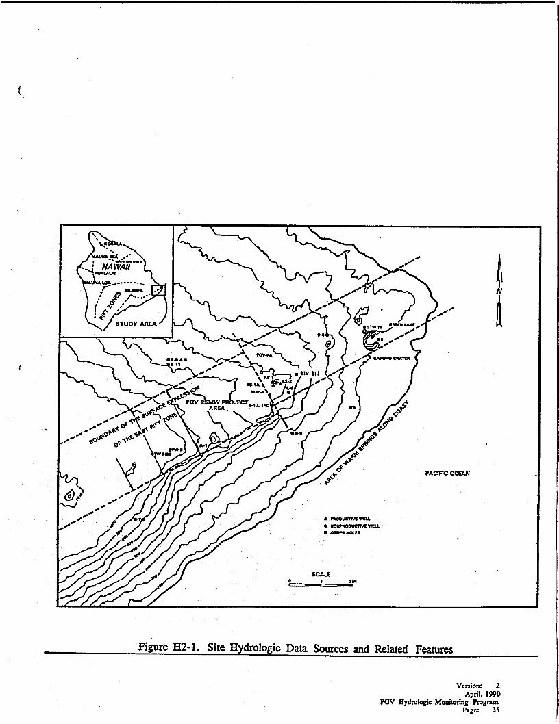
related features relative to the site hydrologic system are shown on Figure H2-1.
Investigations related to the geothermal development of the area have been ongoing
in the site vicinity for about 20 years. Much of the work has evaluated the geologic
setting and hydrothermal characteristics associated with the deeper reservoirs below
the shallow ground water. Details of the background studies conducted in the 1970s
and early 1980s are included in several reports developed by Thermal Power Company
(TPC), the previous operators of the PGV project. Three specific studies done which
include much of the pertinent data and information related to the hydrogeology and
hydrochemistry of the shallow aquifer system at the site include Kroopnick (1978),
Weiss Associates (1983), and Thermal Power Company (1986).
m.l GEOLOGIC SEITING
The purpose of this section is to. present a summary of the geology that has been
described by other investigators for the site area.
The project site is in the southeastern part of the Island of Hawaii within the Lower
East Rift Zone (LERZ) of Kilauea Volcano. The area is characterized by vesicular,
young, sub-aerial basalt lava flows and high annual rainfall.
Weiss (1983, p. 4) reports the following related to the rift zone and the dike systems
that influence the areas vulcanism and geology:
Version: 2April, 1990
pav Hydroloeie MonilOrinr fro&nmPage: 9

•(The rift zone)•..is a zone of linear fissures, faults, cones, dikes and other
volcanic features that extend from the Kilauea crater east...(to the ocean).
The basalts that originate along the rift form gently sloping layers
of several inches to more than one hundred feet thick. Along the
rift, the dikes feeding the flows form vertical walls of dense basalt,
and a structure of many closely-spaced vertical dikes results in the
near horizontal, less dense flows.·
The general geologic setting is, therefore, progressively younger overlying lava flows
at depths extending from thousands of feet up to the surface, cut vertically along the
rift zone by an east-west trending dike system. In the· immediate site area, a north
south trending transverse fault and potentially associated dikes cross-eut the easterly
rift zone trend and are thought to be directly linked to the upward migration path for
geothermal waters in the area (FigUre H2-1). .
m.2 HYDROGEOLOGIC SETTING
The purpose of this section is to present a summary of the understanding of the
ground water flow systems active in the site and surrounding area.
The occurrence of ground water in Hawaii was summarized in general by Weiss (1983,
p. 13) based on the results of many earlier investigations by the U.S. Geological
Survey, Hawaii DOH, University of Hawaii researchers, and other local experts. They
identified four main types of ground water in Hawaii, all of which are potentially
occurring in the site and surrounding vicinity. They are basal, perched, dike-confined,
and geothermal. FigureH2-2 is a cross-section conceptually illustrating how these four
types of ground waters occur in 'shallow-aquifer' type zones.
Version: 2April,199O
PGV HydrolOiic Monitoring ProgramPage: 10
I

H2.2.1 Recharge Mechanisms
The site is characterized as being in an area of relatively high recharge, with ground
water flow occurring in interlayered low to high permeability sub-horizontal lava flows.
Ground water flow in the' site area has two primary and one potential seCondary
recharge mechanisms. The primary mechanisms are from precipitation and from local
upwelling of geothermal fluids. Downgradient flow from Mauna Loa may also occur,
but it is unlikely that this secondary mechanism, if present, is as important to the site
area. Perched waters may occur in the area, but their existence has not been
documented.
Precipitation
Precipitation is one of the three recharge sources to the .area. Average rainfall in the
area is reported to be from about 110 to 125 inches per year (Weiss, 1983, p. 5;
Kroopnick, 1978, p. 11). An estimated 73 percent of the rainfall percolates downward
to the shallow ground water table (Eyre, 1977). Recharge to the shallow ground water
system underlying the 500 acre site area would be on· the order of about 3400 to 3800
acre-feet per year based on the estimated range of rainfall and the percolation
percentage provided by Eyre.
IJpweIling Geothennal Fluids
The second primary mechanism for ground water recharge at the site area is from
upwelling geothermal fluids. The vertical pathways for the geothermal fluids are
believed to be first,· in fractures and fault planes adjacent to and associated with the
dikes and, second, in areas such as the transverse .fault that cuts across the site area,
between KS-l and the HGP-Ageothermal research well (Figure H2-1). The upwelling
is further suggested by the characteristics of the shallow geothermal-influenced ground
water (Section H2.3) that has been detected at the site to date.
Version: 2April. 1990
PGV Hydrolo~e Monitoring ProgramPage: 11
DQWDgradient FJow
A secondary mechanism for ground water recharge to the area is believed to be from
ground water flowing laterally towards the site area from the north and northwest,.
down slope from Mauna Loa. The dike systems act as local barriers preventing this
underground flow from continuing to move downgradient towards the ocean. Instead,
the majority of the ground water is believed to change direction moving to both the
east and west along the rift.
m.2.2 Discharge Mechanisms
Discharge from the shallow aquifer systems occurs from three primary mechanisms,
evaporation and evapotranspiration, subsurface migration or lateral underflow, and
extractions for drinking water and irrigation use. There are no surface streams in the
immediate area.
Evaporation and Evapotranmiration
Evaporation and evapotranspiration represent the principal consumptive use in the
area. About 25 to 30 percent of the water falling as precipitation is believe to be
consumed in this manner (Eyre, 1977).
Subsurface Migration Of Underflow
Flow occurs from the site.area and discharges down slope towards the ocean. Spring
and sub-sea discharge of wanD. water along the coast south of. the project area has
been investigated by researchers working in the area. Local precipitation that reaches
the shallow aquifer in the dike-controlled or .. basal flow areas will also move
downgradient away from the site, although the rate and direction of flow are not
documented.
Venion: 2April, 1990
POV Hydl'OIOJic Moaitoring PtoIramPage: 12

Consumptive Use
There ~e a few shallow· aquifer sources that provide ground water for drinking and
irrigation purposes in the area in or south of the rift zone. The amount extracted at
Green Lake is on the order of 50,000 gallons per day (County of Hawaii, Water Supply
Department, 1989, written communication). Volumes for the other wells, if they are
being used, are not known.
Discharges from private lands from springs and shallow wells directly along the coast
also occur, but the quantities are not known and are not going to affect, nor be
affected by, the project activity since they are so near to the ocean and will have local
recharge from precipitation to these areas.
H2.2.3 Flow System Description
Based on the work and site data analysis done to date, the following flow dynamics
are apparently associated with the site ground water movement:
• The net rainfall (precipitation minus evaporation and
evapotranspiration) flows downward into a dike-confined flow
system -underneath the site, recharging both- the shallow ground
water •systems in the dike-confined areas and into any adjacent
shallow basal ground water areas.
• Geothennal waters occur at depth beneath the site arid are
upwelling in the site area mixing with the precipitation recharge.
• Most ground water moving laterally down slope from Mauna Loa
does not reach the site area as it is blocked by the rift zone and
dikes. Instead, most is diverted and flows along the rift zone,
possibly to both the east and west.
Version: 2April. 1990
PQV Hydrologic Monitorinr PropmPage: 13

t. Only a few wells exist in the site and surrounding vicinity which are completed in the
shallow ground water aquifer and believed to be potentially downgradient from the
project area. Table H2-1 lists the wells currently identified as being completed in this
zone. No recent water level measurements are available for many of the wells. Their.-
locations are shown on Figure H2-1.
Table H2-1. Wells in the Shallow-Aquifer
Well Name/Number Elevation
Allison [A]GlW-mGTW-IVMalama Ki [9-9]Kapoho [9-6]Kapoho Shaft [9]
Footnotes:1. Data reported in Weiss. 19&3.Table 4. p. 26.
13256325927428738
Jk.pth
14069029031633741
Last Reported Use
IrrigationAbandonedAbandonedAbandonedAbandonedMunicipal
H2.3 HYDROCHEMICAL SETrlNG
The purpose of this section is to summarize what is understood about the
hydrochemistry of the shallow ground.water aquifer at and in the immediate potential
downgradient directions from the site vicinity.
The LERZ is believed to act as a hydraulic barrier as well as a divide for ground
water quality. Chloride concentrations north of the rift are generally low, and
concentrations south of the rift have been reported to be greater than 1000 mg/l.
Potable water supplies are obtained from the shallow aquifer at three locations:
Pahoa, Green Lake (Kapoho), and Keauohana [9-7]. All are more than 3 miles from
the site. Pahoa is north of the rift and has good drinking water quality. Green Lake
Venion: - 2April. 1990
PGV Hydrologic Monitoring Pro&nmPage: 14

( is in the rift zone and has marginal water quality. The Keauohana [9-7] well is south
of the rift zone about 6 miles southwest of the site and has good water quality.
Geothermal waters have been believed to be influencing and mixing with the shallow
ground water in the site vicinity for some time. In 1986, TPC compiled much of the
background geochemical data for wells in the site area. This was done as part of their
request to the DOH to have the Underground Injection Control line moved so as to
exclude the site and surrounding area from continuing to be designated as a potential
underground supply source of drinking water. Results of their study suggested that
there was no potential for a potable water supply to be developed in the site area due
to the abundance of geothermal-influenced shallow-aquifer waters occurring over a
relatively widespread area near and downgradient· from the site.
The University of Hawaii (UH) Agricultural Station at Malama Ki and the Allison
wells are located south and east southeast of the site. They have elevated
temperatures and levels of chloride in excess of 7000 and 750 mgll, respectively
(Weiss, 1983, p. 26). Both wells may be influenced either directly or as a result of
mixing with the upwelling geothermal waters from near the site. The Malama-Ki well
is not in use. It is located just south of the transverse fault, about one mile south of. .
the .project area. The Allison well, previously used for agriculture as an inigation
water source,· is topographically downgradient, about two miles east, southeast from the
project area.
The GTWID well just east of the project area was drilled in 1961. The initial
sampling of shallow aquifer indicated a temperature of about 200'F and chloride levels
over 500 mgll(Weiss, 1983).
Water samples were taken from the shallow ground water during drilling at KS-l, KS
lA,.and KS-2 exploration boreholes on the property. Samples were taken in uncased
boreholes at depths of about 700 feet, well above the level of the target geothermal
horizons. Table H2-2 summarizes the ranges of constituents for these samples. The
Version: 2April, 1990
PGV Hydroloeic MonilOring PropmPage: 15

( samples clearly indicate the geothennal nature of the shallow ground water in the
immediate site area.
Results of the sampling done to date indicate that the site vicinity has geothermal
influenced waters in the immediate area. Potable·water lies to the north of the rift
zone and, based on the existing data, will not be affected by the upwelling of
geothennal fluids in the area. The relationship of the waters at Green Lake to the
upwelling ill the site vicinity is not established, although some investigators have
suggested they are not connected or affected by the PGV site area. The area near the
Keauohana well is too distant and hydraulically lateral from the site and therefore will
not likely be affected by site-related upwelling. Potentially downgradient locations at
the Allison and Malama Ki wells have non-potable waters that may be mixed with, or
be the direct result of, geothermal waters upwelling locally.
Table H2-2. Shallow-Aquifer Water Quality Data from KS-l, KS-IA, and KS-2
Wells·
8.56002653111007480152200
CONSTITUENT
TemperaturepHNaKCaMgClSO.Si02
Total FeIDS
RANGE OF VALUES 2
115°Fto 9.5 pH unitsto 1000to 94to 65to 30to 1600to 210to 105to 70to 3100
fOOTNOTES:1 - Source of data from Ultem&! files from 'fPC Project.1 - Constituents values other 1ban pH reponed in mgll unless otherwise shown.
Version: 2April, 1990
PaV Hydrologic MonilOring ProgramPage: 16

( H3. PROGRAM DFSClUPTION
The purpose of this section is to outline the scoPe associated with the seven tasks
associated with PGV's Hydrologic Monitoring Program.
There are no anticipated project effluent discharges to the shallow basal or dike
confined ground water. These waters are believed to occur at depths between about
500 and 650 feet below the plant site and surrounding area. There may be a few wells
in the area that provide irrigation-type water supplies. One area near the Kapoho
Crater, ref~ to as Green Lake, will be part of the monitoring program.
The proposed monitoring program has been revised to reflect follow-up discussions
that have occurred with both the County ofHawaii Planning Department and the State
Department of Health, Safe Drinking Water Branch. The revisions have been to:
1. Add an additional on-site monitoring location to the program so that two
monitoring locations within the project area are in place prior to
beginning of injection at the site,
2. Attempt to rehabilitate the GTW m monitoring well location just east
of the site, thereby providing a third data point upon which to evaluate
ground water flow direction in the site vicinity, and,
3. Increase the number of p3IalI1eter analyses at selected locations for the
initial year of monitoring.
The revised progmn now consists of seven tasks as follows:
Task 1 - Date .Base UpdateTask 2 -Locating On-Site Monitoring WellsTask 3 - GTW ill RehabilitationTask 4 - Completing On-Site Monitoring WellsTask 5 - Background .Sampling MeasurementsTask 6 - Continuing Sampling and MeasurementsTask 7 - Reporting
Vc:rsion: 1April. 1990
POV Hydrologic: Monitoring PropmPlge: 17

( Details regarding each of these tasks follow. Locations, measurement and sampling
techniques, and data reporting associated with the monitoring program are described
in Chapters 4,5 and 6, respectively.
ID.I TASK I - DATA BASE UPDATE
This task will involve:
* getting permission to access the sites
* review and update the well data for existing non
geothennal wells in the site vicinity (with assistance
from DOH and County staff as available).
* make selected field measurements at selected
locations.
H3.2 TASK 2 - LOCATING ON-srrn MONITORING WEllS
This task will:
*
*
*
evaluate the feasibility of using existing
geothennal wells on the site to be completed as
a monitoring well in the shallow aquifer,
Finalize the location of the monitoring wells
to be located within the project boundary and,
Obtain permits from DLNR for drilling these wells.
H3.3 TASK 3 - m:w m REHABIIITATION
This task will include:
* Getting permission to access the site,* Sounding the well for depth,
Version: 2April. 1990
PCiV Hydrologic Monitoring ProgramPage: 18

( *
*
Mobilizing a drill rig and cleaning out the well, and,
Sampling the well.
An alternative location for this third hydrologic monitoring point will be developed m
conjunction with the County and DOH if rehabilitation efforts are not successful.
B3.4 TASK 4 - COMPLEI1NG ON-Srrn MONITORING WEllS
This task will include completing two on-site monitoring wells. Ifone of the
locations involves use of an existing well, then the scope of this task will
include those related actions.
ID.S TASK S - BACKGROUND SAMPLlNG MEASUREMENTS
This task will include documenting background conditions for all selected
wells by conducting an initial round of complete water level measurements
and water sampling at all monitoring locations prior to beginning of
injection of geothermal fluids.
H3.6 TASK 6 - CON'IINUlNG SAMPLING AND MEASUREMENTS
This task will include implementation of the proposed monitoring program
by continuing measurements and sampling on a quarterly basis after start of
injection.
B3.7 TASK 7 • REPORTING
This task will involve providing reports on a semi-annual basis as required
by the GRP.
Version: :1April. 1990
POV Hydrologic MonilOrillg ProtrsmPage: 19

( H4. SITE DESCRIPTIONS
The purpose of this section is to describe the setting of locations associated with the
proposed monitoring program.
The locations for the monitoring of ground water conditions are to be finaJired based
on the results of the initial task activities. At this time, however, there are five known
off-site locations, at a minimum, that would be measured and sample analyses
obtained, at least for themst year of monitoring. In addition, two on-site monitoring
wells will be sampled prior to start of injection. Other locations may be included as
a result of the update of the data base for the area.
H4.1 EXISTING OFF-SITE LOCATIONS
There are five of-site locations that will be part of the initial annual monitoring
program. These, shown on Figure H2-1, are at the:
• Municipal supply in Pahoa [9-5A,B; 9-11],
• Municipal supply for Green Lake (Kapoho area),
• 'Allison' [A] well on the Pohoiki Road, and
• Unused Malama Ki[9-9] well on the University of Hawaii
Agricultw:al Station, and
• GTW m Monitoring Well
PAHOA £9-5A,B: 9-111
The town of Pahoa is served by three wells which tap the basal ground water at depths
of up to about 800 feet. below the surface. The supply is low-temperature, low
conductivity fresh water in a location about 3 to 4 miles upgradient from the site, north
of the rift zone.
Vel'$ion: 2April, 1990
PGV H)'drolo:ic: Monitoring ProgramPage: 10

( One of the wells at Pahoa is a proposed monitoring location since it will serve as a
source for documenting levels of constituents in non-geothermal ground waters.
Coordination with the Hawaii County Department of Water Supply will be maintained
so as to supplement, where required, their ongoing monitoring of this public drinking
water supply.
GREEN LAKE £91
This is a municipal water supply that County Officials report comes from a thin layer
of fresh ground water overlying brackish or salty water. The supply was developed by
excavation to the water level with a bulldozer, installation of piping and refilling the
hole, leaving a piping conduit for the water to flow from the source.
The location is included since quarterly monitoring of the Green Lake water supply
is a condition of Condition 10 of the GRP. Coordination with the Hawaii County
Department of Water Supply will be maintained so as to supplement, where required,
their ongoing monitoring of this public drinking water supply,
ALLISON WELL rAJ
The 'Allison' well is a private well that has been used in the past for irrigation. Its
current use has not been checked yet. It is located just off the Pohoild Road about
three miles east southeast of the site. Weiss .(1983, p.26) reports the well is about
140 feet deep and has a reported· temperature of about 110°F, chloride level of about
750 mgll, and conductivity of about 2000 micromhoslcm.
The location was selected as a proposed monitoring location since it may be
hydrogeologically downgradient from the site and in an area that is already influenced
by geothermal waters. Permission to access the site has been requested. To date, no
approval has been granted. When obtained, coordination with the current owner will
be maintained so as to supplement, where required, .any ongoing monitoring that the
owner may be doing for this well.
Version: :2April, 1990
paV Hydrologic Monitoring Pro&ramPage: 21

MALAMA KI £9-91
The University of Hawaii maintains an Agricultural Research Station in the Malama
Ki Research Forest Area just south of the site. A well, located at a ground elevation
of about 274 feet, was drilled to a depth of about 316 feet on this property in the early
1960s (Weiss, 1983, p.26). It was not used, perhaps because of its elevated
temperature of about 140°F and its chloride levels over about 6000 mg/l. Sampling
was done monthly at this location from January 1980 until June, 1981 as part of
background studies of ground water in the area (W. Burkhard, personal
communication, December, 1989).
The location was selected as a proposed monitoring location since it appears to be
potentially downgradient from the site and in an area· that is already influenced by
geothermal waters. PGV has contacted the University of Hawaii and obtained
permission to sample this well. Coordination with the University of Hawaii
Agriculture Department will be maintained so as to supplement any ongoing
monitoring that they may be conducting.
GTW ill MONITORING WELL
This well is currently abandoned and a blockage exists in the well at a depth of about
270 feet below ground surface. The well was drilled as one of four geothermal test
wells along theLERZ in 1960 and .1961. It was originally completed to a depth of
about 690 feet, about 130 feet below sea level. As noted in Section H2.3, initial
sampling done encountered high temperatures of about 200"F and chloride levels over
500 mg/l (Weiss, 1983).
PGV has obtained permission to access the property and clean out the well. A driller
has been contracted and should begin work in mid-April. Cleanout is expected to take
about one week. PGV will maintain access and -sample and measure the well as part
of the ongoing Hydrologic Monitoring Program.
Version: 2April. 1990
PGV Hydroloric: Monitoring PropmPage: 22

H4.2 ON-srrE LOCATIONS
Two monitoring locations will be situated in the south and north half of the project
area. This will complement the GTW m location and allow a ground water flow
direction to be calculated in the immediate site vicinity. The location in the south part
. will be as close to the injec~on site (Wellpad F) as possible. The location in the north
part will be near Wellpad A if an existing well is used, or towards the Kapoho-Pahoa
Road if a new monitoring well is drilled.
Once the locations are finalized, applications will be submitted, the required permits
obtained, and the wells will be drilled, completed, and sampled. The wells will serve
as dedicated monitoring wells for the hydrologic monitoring program.
H4.3 ADDmONAL LOCATIONS
Any other locations identified beyond those described above in Section H4.1 will be
added to the monitoring plan and described, along with the rationale for their being
included.
•
Version: 2April. 1990
PGV Hydrologic MonilOring ProgramPIge: 23

c. lIS. MONITORING EQUIPMENT AND OPERATION
The purpose of this section is to summarize the types of equipment and techniques
used to perfonn the field-related measurements and sampling activities of the
monitoring program.
HS.l WATER LEVEL MEASUREMENTS
Water level measurements .will be recorded for those wells identified as an integral
part of the monitoring program.
Water level measurements will be obtained utilizing an electronic direct contact
detection probe with a calibrated cable/tape for direct measurement at the top of the
well casing. Calibrated cable/tape length shall be sufficient to measure water levels
in the deepest wells identified. The metering device shall be equipped with an audible
signal and light to indicate water level contact. Specifications for equipment similar
to what will be used for this type of activity are in Appendix H2.
Water level measurements shall be conducted at each individual well prior to any
additional testing or sampling of that particular well. All measurements will be
obtained utilizing standard protocols for the equipment described in a .separate
'Operating Procedures' document to be finalized as the program is implemented in the
field.
HS.2 WATER QUAUIY SAMPLING AND ANALYSIS
Water samples will be obtained .from each of the wells identified for determination
of selected physical and chemical characteristics of the waters from those wells to
which access can be readily obtained.
Version: 2April, 1990
paV HydlOlosic Monitoring PropmPare: 24

( Samples will be obtained from each well according to the characteristics of that well.
Wells equipped with pumps will be sampled from the most suitable ported connection.
Those wells not in use or not equipped with pumping devices shall be sampled with a
stainless steel bailer lowered into the well by winch line to retrieve the volume of
water required for each sample.
At each sampling location, standardized equipment cleaning will be carried out prior
to obtaining each sample. Ptotocols to be used for sampling will be provided in the
supplemental 'Operating Procedures' document to be finalized when the program is
implemented.
Selected parameters values will be determined at each site upon retrieval of the water
samples from the well. The field analysis will include measurement of:
• pH,
• temperature,i
conductivity,•• salinity,and
• chloride.
These measurements will be obtained· by using calibrated instruments specifically
designed to directly measure these physical and chemical parameters within the
operational constraints dictated by site conditions. Specifications for equipment similar
to what will be used for this type of activity are in Appendix H2.
Water samples will be submitted for the remainder of the analyses to an EPA or a
State-eertified laboratory. Samples will be transferred from the bailerlsample port
directly to appropriately prepared containers supplied by the laboratory. Samples will
be labeled, and stored and transported in a chilled state in insulated containers to the
laboratory.
Venion: 2April. 1990
POV Hydrologic: Monitoring ProgramPage: 1S

( Parameters for analysis by the laboratory will, at least for the first year, include
selected parameters that are related to underground waters that provide a public
drinking water supply. These parameters are listed in Table HS-l.
In addition, the initial year of sampling at all monitoring locations will include, as
requested by the DOH, analyses for other organics and other parameters
recommended by DOH. These are listed in Appendix H3. After the first year,·
sampling will not include all of these parameters since there are no sources for many
of these constituents associated with the project.
In addition, analysis will be done for the following five constituents which can be
associated with geothermal reservoirs:
* Lithium
* Vanadium
* Boron
* Silica
* Bromine
* Nickel
The results of the quarterly sampling will be reviewed at the end of the first yeM to
determine if there is a need to supplement the analysis or if the number of paxameters
can be reduced. Any recommendations for modification to the sampling program
would be included with the semiannual· report and submitted to the county for
approVal.
Version: 1April. 1990
rov Hydraloeic Monilorine ProeramPa&c: ~

---------------------
(
Table HS-1. List of Water Sample Parameters for Routine Analyses
Drinking WaterMaximum Contaminant
Levels
Inorganic ConstituentsArsenicSeleniumMercuryCadmiumLeadChromiumBariumSilver
Secondary ConstituentsTotal Dissolved SolidsColorCopperFoaming AgentIronManganeseOdorSulfateZincpHCorrosivity
Other ConstituentslithiumVanadiumBoronSilicaBromineNickel
0.050.010.0020.0100.050.051.00.05
500.015. color unit1.000.500.300.053.00 ton
250.005.006.50 - 8.5 scaleNon-corrosive
Venion: 2April. 1990
PQV Hydroloeic MonilOr1ni ProgramPaie: 27

H6. DATA REPORTING
The purpose of this section is to summarize the frequency; content, and format for
the hydrologic monitoring program data.
H6.1 FREQUENCY AND CONrENT
In compliance with permit conditions, semi-annual reports of the data will be
submitted thereafter, along with the project status reports on February 15 arid August
15 of each calendar year. The initial submittal will include infonnation regarding all
well locations, and as-built diagrams relative to GTW ill and the on-site monitoring
locations.
Subsequent reports will be in letter format and will include activities conducted during
that period, laboratory results of sampling conducted, and recommendations as
required.
H6.2 FORMAT
Reporting fonnat will incorporate standard forms and reporting protocols established
for similar environmental compliance monitoring programs. The forms and protocols
may be modified to reflect the project specific conditions.
Venion: 2April. 1990
PGV Hydrologic MonilOring PropmParc: 28

( H7. QUALITY ASSURANCE PROGRAM
In any program thatreql1ires a substantial data base, the credibility of the data must
be assured before any derivations from it can be reasonably made. In monitoring
programs, the two types of activities necessary to assure the validity of the collected
data are Quality Control (QC) and Quality Assurance (QA). Quality Control activities
are the primary avenue by which the data are kept within prescribed control
conditions. The field QC activities are carried out by the site technician while in
house QC activities are performed by experienced personnel involved with the data
reduction and analyses. Quality Assurance activities ensure that each QC activity is
performed and documented completely and accurately. A control loop is thereby
formed such that if a QA check indicates that an out-of--control condition has been
allowed to occur, then the related QC activity will be modified or strengthened to
eliminate future occurrences.
All activities of the PGV hydrologic monitoring· program will be conducted in
compliance with a strong and effective quality assurance program. This program will
be managed in accordance with other similar environmental compliance monitoring
projects to a standard similar to that expected by the EPA. Details of the QC/QA
plan established for this project's hydrologic monitoring program will be submitted as
a supplement after details of proposed sampling and measurement activities have been
finalized.
Quality assurance also plays a key role in data reduction and analysis and will be
performed .on a regular basis by a trained professional hydrogeologist. Activities of
the Quality Assurance· program are designed to ensure overall accountability,
traceability, and· repeatability.
Venion: 2April. 1990
PGV HydlOloeic Monitoring ProgramPage: 29

( H7.l QUAUIY CONrROL ACI1VI11ES
All equipment will be calibrated prior to use at the site in accordance with
manufacturers' specifications. Program technicians will be fully· trained in the use of
field equipment and performance of field measurement and sampling actions.
Quality Control activities shall incorporate the· use of the Standard Operating
Procedures (SOPs) for well measurement, sampling, and equipment cleaning developed
from U.S. EPA Sampling Protocols. These will be included in the supplemental
'Operating Procedures' document.
Calibration and use of equipment shall be conducted in accordance with Standard
Operating Procedures developed for each type of equipment and the manufacturer's
recommendation for operation and calibration of each unit.
Irl.2 DATA QUAIITY ASSURANCE ACllVITIES
Quality Assurance related to all project measuring and sampling activities will include
documenting that field activities were conducted in accordance with the required
procedures and recording all field data on forms in accordance with the monitoring
contractors standard internal Quality Assurance program.
Quality Assurance related to water sampling shall also include the use of blind
duplicates, field blanks, .and trip blanks as required to assure environmental control
and external laboratory quality assurance.
Data will be reported by the hydrologic consultant, and interpretations and calculations
will be checked independently.
Version: 2April. 1990
pav Hydro.loeic Monitoring PropmPage: 30
• • -;.;:1'

( H7.3 LABORATORY QUALITY ASSURANCE ACTIVITIES
The laboratory selected for analysis of the samples generated during this monitoring
program shall be certified by the EPA or the State of Hawaii Department of Health
to conduct those analyses required in this investigation.
Laboratory Quality.Assurance is the responsibility of the laboratory. However, the
laboratory may be requested to provide documentation of its QA procedures for any
of the required analyses at any time.
In addition, blind duplicates and field blanks shall be included in each quarterly
sampling for a to determine if the test results are reproducible. If required, duplicate
samples may be analyzed by a second independent laboratory for reproducibility of
results.
Duplicate samples will be provided to DOH for their independent analysis, upon
request.
Version: 2April, 1990
PGV Hydroloric MoailOrinr ProiramPage: 31

H8.REFERENCES
Eyre, P.E., 1977. A hydrogeologic study of an area around the Hawaii geothennalprQject wen HGP-A. unpublished.
Kroopnick, P.M., R.W. Buddemeier, and D. Thomas, 1978. Hydrology and
GeochemistrY of a Hawaii Geothennal System: HGP-A,prepared for National
Science Foundation Grant GI-38319, Hawaii Institute of Geophysics, Honolulu,Hawaii, 64 p.
Theimal Power Company, 1986. Petition to Modify the VIC Line in the Lower East·
Rift Zone, Puna, Hawaii. Internal report submitted to Hawaii State Department of
Health.
Weiss Associates, 1983. Hydrology of the Puna Area, Hawaii, Unpublished Report
for Thermal Power Company, San Francisco, CA.
Version: 2April, 1990
PaV Hydroloeic Monitoring ProgramPage: 32

(
FIGURES

SCALE0:. I 10 15 2D MJ, .
ISLAND OFHAWAUo
SOURCE: State cf Hawai. Depar'tment cf PIannlng ana e:a1Cmlc Oevelopment.STA1lS11CA1. BOUNOARlES A-15. 1980:14-
Figure HI-I. Key Location .Map
Version: 2April, 1990
PGV Hydroloeic Monitoring ProeramPaec: 33

1000 0 2000 4000
SCALE.C:ONTOUR .NTERVAL.20 FEET
.5 0 1M.
i· .... -...-
Figure Hl-2. Site Vicinity Map
Version: 2April, 1990
rov Hydrologic Monitoring ProgramPage: .34
oSCALE, tIM
PACIFIC OCEAN
Figure H2-1. Site Hydrologic Data Sources and Related Features
Vcrsion: 2April, 1990
PGV Hydrololic MonilOrinl ProgramPalc: 35

Stello'n dro"" to "', .. co'dero
~....(Jqc:a5~
t-i
U~G)
ac::3Q.
~~~
000c:
~:30~
~Q.
~t1~£!.
~ 0
'" '0
~3g-:::5'0
§.~jl' <Z ~~. ~
~ a'2: g ~.
w';1~"....
0I98~
~<-;'----lJ""'" ed • , Ii Ie ---------'..""11.01..<----
FRESIt WATEn/SALT WAlEn/ •••• !HTERFACE • a t _0 e....
----E'oded .'a'e'---------.""I
11'0'" ,,, poll.,o.'ofta' flo...perched on alluvlv",

PUNA GEOTHERMAL VENTUREHYDROLOGIC MONITORING PROGRAM
APPENDIX HI
GRP CONDmONS RELATIVE TO THEHYDROLOGIC MONITORING PROGRAM

( PUNA GEOTHERMAL VENTUREHYDROLOGIC MONITORING PROGRAM
APPENDIX HI
GRP CONDmONS RELATIVE TO THEHYDROLOGIC MONITORING PROGRAM
"lO.Prior to commencing any geothermal well drilling, testing, production, orinjection activity approved under this Geothermal Resource Permit, thepermittee shall submit to, and secure the approval of, the Planning Directorof a hydrologic monitoring program. The program shall, at a minimum,provide for the quarterly monitoring of water levels and appropriatechemical species from existing wells completed within the shallow aquifer inthose areas downgradient of the project area, including the Green Lakewater supply, as well as from a well located within the project boundary andcompleted within the shallow aquifer. The monitoring, sampling, andanalysis protocols shall be clearly defined in the program submitted to andapproved by the Planning Director. The monitoring and sampling shall beconducted by a qualified cOntractor, and the samples analyzed by a~ualified
laboratory, selected by the permittee but subject to the approval of thePlanning Director. The selected contractor and laboratory shall operateunder contract to, and shall be funded by the permittee. The program shallmonitor the shallow groundwater immediately prior to, and during, allperiods of well drilling, testing, production, and injection activity approvedunder this Geothermal .Resource Permit. The data obtained shall be
. submitted to the Planning Director in accordance with the requirementscontained in this Geothermal Resource Permit for submittal of all collectedenvironmental monitoring data. The County shall make random checks ofthe ground water supply no less than every two months. to

PUNA GEOTHERMAL VENTUREHYDROLOGIC MONITORING PROGRAM
APPENDIX H2
EXAMPLE EQUIPMENI' SPECIFICATIONS

(
MODEL 101
Flat Tape Water Level Meter
For measuring the depth of water Inboreholes, standpipes and wells, theAat Tape Water Level Meter (dipmeter) Is the most reliable and accurateof the Solinst Water Level Meters andis easy to operate and read.Also available is the Model #102Coaxial Cable Water Level Meter foruse in applications with small sizetubes.
Operating Principle
The standard Flat Tape Water LevelMeter(dipmeter) usesa0.59-(15mm)diameter probe constructed of nickelplatedbrass. This is fitted to apermanently marked, mediumdensity, polyethylene flat tape which contains twostranded stainless steel conductors.The probe Itself incorporates an insulating gap around a central stainlesssteeleledrode.Whencontad Is madewith water, the ciraJit Is completed,sending a signal back to the cabledrum where a clearly audible buzzeris activated.The water level can then be determInedbytaking areadingoff thecable,at the topof the borehole,pipeortube.The cable is housed on ahigh qualitystorage and winding reel equippedwith a brake. The reel has a convenlentcarrying handleandasturdy stand·alone design. Standard controls include abattery testbutton. on/off switchand sensitivity adjustment.
(SOO) 648·9355
Features
ACaJratemarkings at em, 112- or 1120- intervals.sensitivitycontrolwhichadjusts to suitwater conductivity.
Reliablepermanent. hot stamped markings.
Long Liferugged, free standing reel.corrosion proof components.standard 9v battery.replacement probes and cables avail·able.
Aexiblelengths up to 1650 't. (500m).stainless steel probe and other.op·tlons available
e \1\
\,\
'l\t\
e \\\
\ \
@ ,-"'\... \
\
Measurement Options
The flexible, polyethylene flat tapegivesvery accurate readings becausethe permanent maridngs are at closeIntervals. The high strength stainlesssteelconductorsprovide strength andthe design prevents it from adheringto wet surfaces In boreholes andtubes.Markings are permanently embossedonto one side of the tape and areavailable Inyourchoiceofthreescalesor, if preferred. any combination ofscales, one on each side.
M1 Feet and Inches: with maridngsevery 112-M2 Feet and 10ths of feet: withmarkings every 11200.M3 Meters and centimeters : withmarkings every em.M4 Markings both sides: any combi·nation of scales.
\\\
\\
·20·

(
S-C-T MeterYSI Model 33
• Measurcs Salinity. Conductitity. Temperature• Direct Reading Water Quality Meter• Portable, Banery-Powered• Designed For Field Measurements
INSTRUMENT SPECIFICATIONSC....duClh·ky Ra1l1:"5:
U k, "'.lllXII""I1t,,,,~," ''''~e la..~"" ke.tJabllll~ l'i ," ..ale. litrl"'lc.. cba..: J".l .11 rC;Nlft~ .pl... I ~ ... '.
Salinil)' Ranlc:C~ Pl'T (n"" - ~ I.· ,~H·. ,c;,d.,btlil~ " Z),I'r..a:m... abuv<: "'C less Ill:tn
: 1.1 PPT al oil' I'I'T. : II 7 l'l'r .. 211 l'l'r. JII........obe.
Temperalure bnie:• ZIG • ~rc. """""blltl~ II !SOC" I/lNn - : I... n't' I;m... .:.11 I'C ..I -re.::11.f.-c llI·IS'C. "'U'III.~",
100 or 600 H. Uper:olivn:100 Hl rut $1111 """"ll""~< ...,lIkHl..1flllU Itl ...... , ..~""r•.........,IIYlly and .alinil)'
Qnl~·
Ambienl Temperalure:UPCnlQ (n"" • ~ Iv ,"~ 'to M••. oI"illl 1'4 ... 'c.....in!; pcr "(" .1Ianj;C inamlllcnI. Nea:lt~,ble "'III II 'col line I......IU~col.
Probe:InlCl",1 Cund"':II'·lIy"cllll""alUn: prubo: III· oIu'....1.: plaol.... 1","·oI;a. ~ r lone:13. 5cml. cl....l.nl ..,... • ~: 11.1 cm I Em" leu lhan :: ~'~"i ICatline:5lclI
~inilY and Co""...:II..1~. '. 1/ I''C (I'" h:mpc:talun: nlC:IO..rcmcnl ;d ere, ::O.)"CIII .atrC. Ptubo: ck:clIlkk, ,·.n bc'epiallnllcol b)' u.lne: I/Ic "",rumenl plus
plalinillnl w1..lIu"Power Supply:
Two EVCIC;Ny E95 """<rl~' u, clIuI.alcnl ....... klc 2\x, h...no ..per•• i...".lounamml Siu: . .
'I. 16 a ~S .:m: : L~ I."·: , h\~ , ICI In ." II.. I
Ordertac rarl Number.:'1'51 M...rc:1 \, s·(':r ~k.<,
Y51 3JIIl 5·<:·T I'r."..,. II" 1.: dill I
\'51 JJII S-C:.T 1'"obe.:\If "' ' ..11 1".., "NI~", 1.:...., 1.. 11 .... pl"".: ..n "X";dler pruhe numbo:r a.....I ,~ I.:n~lh I''''''''.~" .of h...~~, .uppl....... Wllh
>lUI':IIC red. fur k ....1- "'~I II .:.NII...II... " .. y
'"51 .""lll'l.unlllll~ ~.""''''". 1 ..,YSI 'lI~ll·.,.~.n~ l"a..:
T-L-C MeterYSI Model 3000
• Portable. Self·Conlained Water QualityMeter
• Measure Temperature, Level,Conductivity
• Groundwater or Surface Waler
,INSTRUMENT SPECIFICATIONSTcmpenIUR:
Ittuttt: - 5.0 10 +so.lre. A«urlK"/: :0.3OC melucline probe. It,SDlllliDII:O.IOC.
Lnd:. Ittuttt: 0 10 ISO Ct. AtnutM:7: : I" per SO' of cable.
CGaducdYltJ':N-uu./ Ittuttt: 0 10 2.000 IIUlUmllosIcm 10 to 1.000 1IJIl/lOSIcm1. 010 10.000IlIillimllOSlcm cO 10 20.000~cml. At:turIK"l: : 3'110 o( fullscaJc inclucl,ncpnIbc. Il,SDI..,Wn: t part In 2.000.
TClllpenlure-Compcasaud CllOductbflJ':
N-u.oJ It""tt: 0 10 2.000 millimhoslcm 10 II) 1.000 fIJI\hOsIcml. °to 20.000Illillimhostcm CO 10 20.000 JIom/lO$Icml.~: :.'110 of full scaJc incllldinCpn>bc. It,sulllliDII: I part In 2,000.Nor,: hnCC lICNaIIy ClIds lit 1.999 or 19.99.
Probe ucI Cable:I'rubc Iw cpve bod)' and n:moyablc awnless IlCeI _iCbe aIladlcd to dunblcpol)'lll'Cllwlc-jactcted cable. Probe Iw 1"1IOmiAaI cliamcr.cr, .v." len¢'. Cableis 150'lone willi dcpdIlllaItlnp every IT;a waIl:r-tielll MS connector anachcscable 10 lnsll\llllClll. Cell conswu is K-5.Otcm :0.1. Emx 1ess,IhaA =Z%o( JadiDes (or condUCllYiry, : O.I"C (01 tanpctallR.
AmbIcaI TCIIIJ'Cf'lIlIIR:oII) sere.
HumldilJ':0pcnIcs~ &IIy Ilumidily COCIIllIion if ICals arc iIIUct and desiccanl 1$ Inp~.
Cue:WaIct.alllleu MIL·T·2UIlIlC; lIICilbs 7.' puunds.
Power Supply:Si~ "C" .ue hcavy-duly caltlon••inc IwIenCS proYIde bcll.cl' dwI IZOO how,olpCl'aIion bI>Cd ... 4 huurs usc per <lay. Alkaline cells provide bener I/Ian 17'101I"",s. Luw.Jw1Cty 1ft<lio:1Itor wams when II) ,eplacc baacncs.
OnIcriac Par1 Numbct's:YSI Model 3IlOO T·LoC Mer.crYSI JO.lO TC>I Probe IIesIS calibnllOft'YSI JO~ Replac:cmcnl Probe, Cable and Rocl AssemblyYSI JI.-o !'IaulUanl Suluuon, 111•. C(or probe __nance,
YSI »4, l'Iallll't1nllnslNmcnllrut ptUbc nwnlC1WKe,
(
021000 SA 210 Ponable ptifmV MeIer lorhand·heldIbench·lop use. DIg.atLCD meter comes in carrying caseWith comllinallOllllH electrOde.anached ShOt!lng plug. Ihree fiOrnI solution bOnles. one 150 mlllealcet. electtoae lIOIder. SUDllOrtrOO. rOO gutde. one paCkel pH 7buller one 9V flanery. IllstrUClIOnmanual. aM lralllttllJ QUIOe
025000· SA 250 POIlable pH/mY/tempera·ture Meter lor ha/ld·hela/bendl-lopuse. Diolla!. LCD meter comes wrthcartying case. Model 81·56 ROSSpH eteetrode. ATC prObe. attaChedsnoRIllg plug. one 3M KO 2oz.boIlle 01 filfing sotUlion. Ihree 60mI solUlIOll llollles. one plastiCbeaker. e1ectroae hOlder. suPPOrtrOO. roo guide. one paCket pH 7llufter. one 9V llallery. IIlSIIUClionmanual. and trall1lllg l)IJIde.
OPflOl'ML ~CCESSOR/ES FOR SA 250. SA 230.AND SA 210 METERS.020041 ShOUkler strap and meter hOlder
tor IIanos·lree operation. Great torplant Of bela work
020045 SlaDle electrode stand with heavybase. rOd. and holder.
023(0) SA 230 POI1aDle pH/mVllempera.lure Meier lor hand·heldlbench-lopuse. DlIJllai. LCD meIer comes incartying case Mlh cornbinatlOri pHetectrooe. ATC probe. anachedShORing plug. three 60 mI solution DOllies. one 150 mI beaker.electrOde hOlder. SUllPOIt roo. rOOgUide. one paCket pH 7buifer.one 9V battery. IllSlIUClionmanual. ana lratnlng gUide.
. .
.. .
.. .
ADVANCED FEA TURES
pH Autocal. or'manual buffer entry.ChOice 01 olsplay resOlutIOn.AdJustable lsopolenliai point.Automatic temperature compensatIOn.-"0 slip' gnp lits comlOttably In one hand.Dutable. dust and splaS/l resIStant.LlIle or battery operated.
SIMPLE TO USE
Prompllng. by advancing to next step.ASSistance Cerror) codes.
THE SA 250 METER IS FORTHE CUSTOMER WHO WANTS:
An accurate and portable pH system.A pH meIer that IS supplied complete andre:2dy to use. WIth allihe accessones youneed 10 make pH tneasuremenlS III (hef,eld or lab.
ADVANCED FEA TURES
Automallc temperature compensation.'No slip' gnp lits comlortably ,n one hand.Durable; dust and splasn resistantRecessed control knobs prevent settings/rom being changed unlntenllonally.Line or battery operated
THE SA 230 METER IS FORTHE CUSTOMER WHO WANTS:
An economical meterwith the addedaccuracy and convenience 01 temperaturecompensated pH measurements.
Same fearures as the SA 230. bUI withoUlautomatIC temperature compensation orlemperature readout. With manual temper·ature compensatIOn.
rile SA 2:10 ....,., is ,.,ppUettwilh.o lleSl·pe,/..,.1lHI9 ROSS.comC_loon.•""-l'"lI«Ir pH• /eeltotte .lIa A rc /HOlle to,'••r. ecCUTlI. ,,,I. /10 ",.11.,
_llh. """uI. './IIIM'.''''.'
Til. SA 230 &/.,., 'S S/IOWII wilh.. COllveniell1 ,.../J..- UWIIa ..
•lUrar ~/Id tOi lI..llUltae•• '"""lie.....e* .".011 ,." ,../Id.-k.o.ap."",ioll.
BOllllh.. SA 23<1 ""'" SA 2'0"'.te,. IY••• .,.,.,. t I.tH ",vlange lal e&:o"....HC411f1JO' •
pot.""., CI",.""••.,.~"""
nil

(
./
,.Ii
II·.J1!4·tl
.~ :;
.l J
11'-" .t·J~i..
" .
.J')
. 0-1
"=> .
.~
j~"I·~' . .
· 31·
Regular Bailers for Well Purgingand Sample Retrieval
TIMCO'U bailers are available in Teflon", stainless steel. PVC and acrylic insizes from 0.84- to 4.5" (21.4mm-114.3mm) diameter and l' to 6'(31Cm-183cm) lengths. ,All are solvenl free. and have a flush "V" Ihreaded ball check for ease ofdecontamination. This design permits the addition of a body extension pieceto increase cap.1t.ily.
lhe ball check design allows for the inclusion of a Viton' "O~ ring in all butthe Teflon'opaQue model. The Vilon·· ..O.. ring provides a leak free joint. It isinert and will not compromise the collected sample.
The bail, an integral part of the bailer body, permits easy attachmenl of asuspension cord. Stainless steel models have a fixed bail.
(800) 648-9355

PUNA GEOTHERMAL VENTUREHYDROLOGIC MONITORING PROGRAM
APPENDIX H3
UST OF ANALYSES FOR FIRST YEAR SAMPLING PROGRAM

Department of Health Laboratories Form Number _
(
SAFE DRINKING WATER BRANCHCHAIN OF CUSTODY & EDB/DBCP CONTAMINANT REPORT
Water System Name .Number _
Sample Location __
Well Log # - Sample Point" _
Type of sample: Routine_ Special _
Collection remarks __
Sample Chlorinated
Sampler(s) " __
Date: _____________ Time: _ Sample Location
Relinquished by: Date/Time Received by: Date/Time
Dispatched by: Date/Time Rec'vd for Laboratory by: Date/Time
Method of Shipment: Seal Intact: Yes _
Sample Lab URelinquished by: Date/Time Received by: Date/Time
Sample Lab " Locked in Refrig Date/Time Rem'vd from Refrig Date/Time
..
Regulated Compound ND NQ RESULT* Method Date Analyst Lab 11
Ethvlene Dibromide < . < • ABCD1.2-Dibromo-3-Chloroorooane < . < • A BC D
1/90
'* Measured in micrograms per liter (ug/l) unless otherwise specified.
HCL (Circle) Y N
Sample Preservation:Methods:A=Purge TrapB=GCC=GCMSD=Other _
Dechlorination:appx 3 mg Na2S203
Reported by: Date: QA Check: Date: _
Forwarded by: Date : _
.... maximum lab analytical date Jaben contaminants contaminant analystUJ results* method analyzed number.... Jevels*
Arsenic 0.05
Selenium 0.01
Mercurv 0.002
Cadmium 0.010
Lead 0.05
Chromium 0.05
Barium 1.
Silver· 0.05
Nitrate (as N) 10.
Fluoride
Chloride· 250.Total .500. - -Dissolved Solids
-
Sodium
*Measured in ~iJJigrams per ~iter (mg/O unless otherwise specifie~.
Analvti-:al Me~~A - Acomic Ab~PhO'\8 • Atomic AbSOt;l:iO"'l; Cllel.aciCl!\-cll1racdonC • Acomic Absor:nior\; 'lamell:sso • Acomic Absorpcio:-.; Ftamclcss CraphUc FurnaceE • Acomic: AlIsorp;iCl:'l;Casc;x,sF • C.a::lmium Rc~uc:ti~n
C _ Colorimetric: wi:.'\ p'cU.-ninar)' distillation
H • Elccuo~c
I - Cas O!rom;uQ&ra?"Y3 - Cravime:rlc: Analysis" • Silver Diechyl-dic.'\ioc:arbonacc1. • Tltrimectic: Analysis:.t - _N - _
I.,
No. of Containers:'---------
----------- ---- - ----Container: No.1
No.2
No.3
No.4
Metals
Hg
N03
TDS/CL/F
Preservative Added (mJ) Signature Date Lab. No.
.-----
Reported by:. Date:. QA Check: Date:. _
Forwarded by:. Date:, ---

!CONTAl1INA.~T MCL*I lab analytical date analyst lab
results* method analyzed number
Trihalomethanes 0.10 A 3 C D
CliLOROFOR.'i A B C D.
3RO~!OFOi\."! A 3 C D
CHLORODI3RO~OMETIi~~E .~ 3 C D
DICHLOR03RO~O~!a~~E A 3 C D
A 3 C D
A :9 C D II ,.
3 C D."".'1\ 3 C D
I ? :9 C Dn
A 3 C D
A 3 C D
A :3 C D
A :9 C D
.'1\ B C D
*Measured in miligrams per liter (mg/l) unless otherwise specified.
Sample ?reservation:
ECL (circle)
Methods:A=Purge TrapB=GCC=GCMSD=Other _
Y N
Dechlorination:appx 3mg Na,s~o3added to satrlp_e
Y N
~eported by: Date: QA Check: Date: _
Forwarded by: ~Date: _

,
i
Regolated Compound MCL'" ND ~Q J\ESULT* Metht'd Date Anal~'st Lab i/
Vinvl Chloride 2 <0.3 <1.0 ABC Dl.l-Dichloroethvlene 7 <0.3 <1.0 ABC DI l.l-Trichloroethane 200 <0.3 <1.0 ABC DCarbon Tetrachloride 5 <0.3 <0.5 ABC DBenzene 5 <0.3 <1.0 A .8 C D1 2-Dichloroethane 5 <0.3 <LO ABC DTrichloroethvlene 5 <0.3 <0.5 ABC Dip-Dichlorobenzene 75 <0.3 <1.0 ABC D
I
Unregulated Compound
l. Chloromethane <0.3 <1.0 ABC D2. Brocol!lethane <0.3 <1.0 ABC D3. Chloroethane <0.3 <1.0 ABC D4. Methvlene Chloride <0.2 <0.6 I ABC D5. trans-l 2-Dichloroethene <0.3 <1.0 ABC D6. l.l-Dichloroethane <0.3 <1.0 ABC D7. 2.2-Dichloroorooane <:0.5 <:2.0 ABC D8. cis-l.2-Dichloroethene <0.3 <1.0 ABC D9. Chloroform <0.2 <0.6 I ABC D
10. 1.1·Dichloroorooene· <0.3 <1.0 ABC D I11. 1.2-DichloroDrooane <:0.3 <1.0 ABC D12. Bromodichloromethane <0.3 <1.0 ABC D I13. Dibromomethane .. <0.5 <1.0 ABC D I14. trans-1 3-Dichloroorooene <0.3 <1.0 ABC D15. Toluene <0.3 <1.0 ABC D I16. cis-DichloroDrooene <0.3 <1.0 A S C D17. 1.1.2-Trichloroethane <0.3 <1.0 ABC D18. Tetrachloroethene <0.2 <0.3 ABC D19. 1.3-Dichloroorooane <0.3 <1.0 ABC D I20. Dibromochloromethane <0.3 <1.0 ABC D21. Chlorobenzene <0.3 <1.0 ABC D22. Eth\'l benzene <0.3 <1.0 A SeD23. 1.1.1.2-Tetrachloroethane <0.3 <1.0 ABC D I24. m-Xvlene }coelute <0.3 <1.0 ABC D t25. p-Xvlene <0.3 <1.0 ABC D26. o-Xvlene <0.3 <:1.0 ABC D27. St\'rene <0.3 <:1.0 ABC D28. Bromoform <0.5 <2.0 ABC D29. 1.1 2.2-Tetrachloroethane <0.3 <1.0 A 3 C D30. 1.2 3-Trichloroorooane <0.3 <1.0 ABC D31. Bromobenzene <0.3 <1.0 ABC D32. 2-Chlorotoluene <0.3 <1.0 A BC D33. 4-Chlorotoluene <0.3 <1.0 ABC D34. 1.3-Dichlorobenzene <0.3 <1.0 ABC D35. 1.2-Dichlorobenzene <0.3 <1.0 ABC D
Unreg Compounds on List 3
36. Bromochloromethane <0.3 <1.0 ABC D37. 1.2.~-Trichlorobenzene <0.3 <1.0 ABC D38. Hexachlorobutadiene <0.3 <1.0 ABC D39. Naphthalene <0.3 <1.0 ABC D40. 1.2 3-Trich1orobenzene <0.3 <1.0 ABC D
1/90

· . - ,; -_. ...
Analytical Method: .·G' - Colorimetric with preliminary distillationH - Electrodet .- Gas Chromatography:J - Gravimetric Analysis
.'
I- maximum lab analytical date labcontaminants contaminant analysten~esults" method analyzed numberw levels*I-
Endrin 0.00020
Lindane 0.004
Methoxychlor 0.1..
Toxaphene' 0.005'0·.
2.4- 0 0.1 .2. 4. 5 -T? SHve, 0.01 ..Total
.10Trihe,lomethaneso'
: " 0
..,.. ..
.
.' ...
... ..
. .
.
.' .' *Measured' in milligrams per liter (mgt!) unless otherwise specified.
K - Silver Diethyl-dithiocarbonateL - Titrimetric AnalysisM - Purge and TrapN - .
. ._- .......-.._-._._-.._-_._- .... R~portedb~;..,·' Date:~ QA Check: Date::..- _
· F!Jnv~ded b~~ __.;. Date:;....-. _

moviug fluid from the wells to theplant. a power conversion unit andtn most cases: Injection wells fordisposal of spent flUids.
Failure DataThe high temperature•. pressure
and chemical compOSition of geothermal fluids are conducive toequipment faJJure (Table 1). A geothermal reservoir Is usuaUy locatedIn an active geologic environmentcontaining faults and fractureswhich Increase thedifflcultyofdriUIng and the poSSibility of adverseenvironmentallmpacL
Detaileddataongeothermal sys-. tern CaJlures are generally not avail
able. The best-documented failureshave been those associated withwells. Unfortunately.even thesedataare often lacking In such Important
. Items as discharge rales. detectionmethod and causeoffallure. FaihJredata on eqUIpment such as surfacepiping and energy conversion components are also Umlled (Sung et aJ.1980: Summers et al. 1980),
On the basis of (allure data collected. a review of geothermal siteptans.and consideration ofpoSSible8uld release points. the follOWingcomponentswereconsidered for faU- .ure analysis:
• wells• weUheac1 assembly• surface eqUipment• diSposal system.
The ground-water quolity impact of geothermal energy systems has yet to be determined,Tnis article offers a discussion ot these systems and the reasons for their failure as they relate to. . future monitoring.
r:N forest L Miller Jr. and Sionor geothermal energy to elec-OOUglas e. Zimmerman triclty Is In a transitional stage of
developmentThe conversioncan beperformed ana~t-effecU~mannerand the types of equipment necessa:y to operate safely and consistenttyare known. but the operatingexperience accumulated to date IsInsufficient to assIst In estlmatlngfailure rates with reasOnable precision. Operating experience In theUnited States Is limited to the Ceysers Known Ceothermal ResourceArea(KCRA)whlchlsJocated 180kmnorth of San Fnnclsco. California.ThIs KCRA Is a vapor-dominatedsystem asoppo~ to the more common Uquld-domlnated systems.some ofwhich are being developed •dsewhere In the United States. Themost active areas of geothermaldevelopment In the United Statesare currently the Imperial vaUey ofCalifornia and sites In northernNevada.lntematlonally. power production at a significant scale from
.Uquld-domlnated reservoirs Is online at Cerro Prieto. Mexico.WaJrakel. New Zealand. and severalsites In Japan.
A number of technologies areavallable for the conVersion ofgeo- .thenna! energy to electricity. The~lecUon of the power conversionunit Is controlled primarily by the .
. chemIcal.and temperature characlcrlsUcsofthegeothermal reser)ooir.
Cenerally there are two basic.types of systems. The flash systemallows tJ1e geothermal flUid to flashtosteam.which Is then used to drivethe turbine. The binary system uUI- : Production WellsIzes a secondary fluid. such as freon Well failure can occur In two dis-orIsobutane. which Is heated by the tlnctJy different operational modes.geothermal flUid to drive the turbine. FalJurecanoccurduJ1ng thedrillingBoth systems are somewhat similar of the well or dUrlng geothermalIn that theyrequire production weUs. fluid producUon.Tocontrol.U~emove-
The technoJ0!tv for the conver- a system of pipes and valves for ment offormatlon nuldsaround the
t~C.A: l:J:- ......... t\ .,J,,·H;:' (I\o.,,:,\i~.•,,~ ~.., (.,I ...4::... _ " • 1\ . ...J.... & ftlm a ,,,,u"U'1' ~ _ A GWMRISOI'ino 1Q82 2:1..JD C? MI\ ~ t.' ")
Background
}.U.S. Environmental ProtectionA#ncy grant to assess s"tandard.and InnovaUve ground-watet monl,oring t~chnlques and sy~tems
_ppUc:d to geolhennaJ energy development Impacts on associated,:round-water systems Is currentlyundeaway. The research effort Isdln:cted toward Integrating monitorIng techniques. legal constraln"ts.production system fault-tree ariaJy,Isand comprehensivesolute transport and geochemical models.AnUclpaled results Will prOVide means toassess sue-specific ground-watergeothermal systems and to Identifythe opUmum monitoring methodology and network design to detectground-water qualltr Impacts.. Themodels wlU allow an evaluation ofpolenUal worst-case Impacts on the
! ground-water system. .
1:1'1 InfonnauononapproxJmate!y80
geothermal energy system fallures\l;'2S compiled and reviewed dUrlng
I. .~ co~e:flithIS study. faUures
I\'e ....'0 rom minor leaks In
pipes and valves to uncontronabledischarge (rom we11sresulung Inahc release of large quantities of
I geothennal OuidoSlaUstica1 analysJsorthe data toUected pro\1des a comparison of (ailure rates (or differentc:omponen.1!i of a geolhennaJ devel-opment Bqlh a review ofworldwidegeolhermal' weU- and plant-failuredata and a failure analyslsuUllzlngfault-tree techniques to assess thefocP' ~Jnts ofground-waler monlIOI)efforts are presenled In Ihlsanlae.
"
. 'J#! r .•~-'p,r..-: ...., . ~. '.
I,. ~~"."\
'~l~' GEOTHERlVlAL SYSTEM"';'~:I' FAILURES: IMPLICATIONS.~ ·FOR GROUND-WATER~I MONITORING'cJ

: ... , . *'
,
•
IIIi.
Ii ),I ..f
• ., ~=..v~ "'••••" ""oN ~wv .
Ing and production. the wen·bore61ze Is reduced with depth. At eachreducUon In hotediameter. theboreIS cased and cemented.An exampleofthecasingand cementingofwdlsat Walrakel. New Zcaland.1s s1'\ownInflgure 1.Numerous toolsand techniques exist (or physlc:aJJy locatingand defining the type and seventyofcasing failures. but onJy a modestamount of data concerning theactuaJ cause of the failure can beacqUired when the (allure occurshundreds of meters or more belowground 1C\'e1.
FaIlures during dnlllng operations can result In uncontrolled discharge from the well bore. ThIs condillon. known as a blowout, Is ofpartJcular concern as uncontroUeddIscharge can last a significantlength of ttme. The costs and difficulty of repalrs are high. Blowout ofa wen Is pOSSiblewhen thefonnatlonflUid pressure exceeds the pressureof the drilling fluid In the well bore.This condition can occurIn zones ofloslclrcuJauon.where the fonnatlonbeing driUed Is either very penneable. has an extensive fracture orfault system or Is cavernous.Blowout pteventers which seal againstthedriU pipe In theeventofaslgnlOcant pressure drop are reqUiredsafetyequlpmentdUring thedrtUlngofgeothennal wells. .
Many Individuals (rom both pn\'ale and governmental sectors bel1eve _that. drtUlng equipment andtechnology currently In use haveproven sufficient to prevent weBblowouts. The Incenttve to preventthiS type of (allure Is bc?me by thegeothennal devetoperbecause ofthehigh costsofdrtUlngoperationsandsubsequent costs of controlling aweD blowout. A typlcaJ well at theGeysersKGRA costs between6825.000 and 61.6 mUUontodrtlland complete. .
Because ofdifficulties In IdentifYing. production weU fallure. thepotential lor adversely Impactingassociated ground-wateraystems Isrelatively high. fallure ofa weB easIngcan range (roma mlnorfracture10" a complete coUapse. Dischargecan beveryUmltedorcanconstttute.the total flow ofthe welL resuiUng Ina blowout condlUon. Indications ofcasing failure can be as obvtous as\'1suaJ diSChargeat the surface orassubtle as a change In the chemlcaJconstituents ofthe Ould. OtherIndicators of casing faJlute Include areduction In flow or temperature.change In the sleam/water ratio. orInduslon ofsand orother(onnatton
24 GWMn/Spring 1962
matenal In the productton fluid.FaUure of the cement between thecasing and the fonnatton Is usuallyassoc1ated withcasingfaUures. Thiscan allow the geothermal ,flUld tomJgrate along the well bore andenter a lonriauon different (romthat In Which the onginal (aUureoccurred. .
A number offntem:Jatcd (actorsmay contr1bute to casing faltu~
• thennal stresses or thennalcycling
• Inadequate cementing of thecasing
•. corrosiOn.The ronowSngscenar1odescr1bes theinterrelationships of these (actors:
DunDg the driUlng ofa wen. formatJonsareencountered thatarehighly penneable.-¥lhen the weDIS cased and cerr,tnted.· a poor~mentbond between the casing
.and the (onnatlon'1s achJeved Inthese zones. aIJoWlng .thecaslDg10 differentially expand and contract. The WeD fs completed andput InlO productlon.1he casingIS subjected to high temperaturevariations causing thermalstresses. (The term thermalcycling Is used to descnbe theexpansion and contraction o(the
casing as It Is aJternately put onproduction and then shut In asenergy requirements or malnttnance of the .weU Of power plantdictate.)ThecasingsUbsequentJyfaUs In thezonewhere thecementbond Is poor due to the thenna!stresses assoclated with productJon. faJ1ure can occur very earl)·In the life of a wen or can occurmuch later when the t:aslng Isfurther weakened by both com>slon and thennaJ cyclIng.Analysis ofcasing failures In the
geothennaJ fields of Italy revealedthat failures were more likely tooccur after large temperature vart·aLJonsand that the lower part ofthe ..casing stnng was more likely to fall
. (eign! et aJ. 1975). .Agaln. thedlfficuJtyIn Identlfylng
the exact causes of casing falfureshould be recogniZed. Dae to thelimited amount ofdata that can becollected. It Is difficult· to precisely Idetennlne the cause o(fallure. Our·lng the time or data collection forthis report both the literature col- I
lected anddiscussionswith govern- Iment and private operators haW'stressed the rapid technological 1Jmprovements In both dnlUng an~cemenllng leChnlqu~s by the gee-

d 5l ' p. , m '"
Figure 1. Typ1cal casing aestgn at Watralcet. New Zealand. (a:tter De1terding.1980).
GNMR/Spring 1982 25
6-5/8" 00 SlottedProduction Casing
•
18"00 ConductorCasing
13-3/8/1 00 SurfaceCasing
Hot Water
~- 8-5/8" 00 IntermediateCasing
limited because ofthe experimentalnature.Umlted Umeperiod and wideWr1aUon In flUid chemistriesduringtht'Se studies. CorrosIon studies ofvarious metal alloyS In the ImperialValley have shown that steels containing either molybdenum orchromium and molybdenum withstand corrosion better than the~bon steel pipes most commonlyused(McCright et al. 1980). Because ofthe lack of operating experience In'Ih~ UnIted States:. esUmates of (allure rates (or surface equipment arebased on data from nuclear power .plants.
670,56m
24.38m
ures have been detected andrepo:1Jrulwith1n60 minutes. Unfortunately.data from the Geysers Is veryAtypicaLThis Isadrysteam reservoirwhich does not require fiashlngandthe Injected condensate has totaldIssolved IiOtlds values that range(rom 300 to 1.000 mglL In contrastto this are sites In the Imperia!Valley where brines are producedWith total dtssolvedsoUdsas hl~h as300.000 mgIL , - . .,
NumerousstudJeshavebeen conducted on corrosIon. abrasion andscale formation ratesat specificgt'Othermal sites. but extrapolation ofthese data Into failure ratcs Is
• 'llrnllaJ maUSll')'. Lr.llH lrom LUt"l1Lu(omla Dlvtslon of OU and Ciast ,dlc-atc there have been no serious~«\bICmswith gcolhennaJ weD drill-
)n that state since 1975~ IndIca11005 are strong that Improved tech
"o!tV has decreased fallure rateS .o('wly constructed wells. As more
• ii;lnls compiled. It maybe possible1&;\\"rify this hypothesiSand to Iden111\' \\'~lIs that are more likely to faJ!
I~: Ihelr age. .
wellhead Assembly .The basis for separation or the
,• \\,,,Ihead assembly from other com
rc"lC'nls of the piping s),stem Is tl}eIrllalaJ foruncontroUed discharge
::.'ahe e\'ent of failure. The wellhead:t!iS('mbly typicallyconsistsofseveral,~\"t'S which are used to regulate110'" (rom the well, In the event oftlilLare of other surface cqulpmenLIh~ valves could be closed to litop
t Do'" from the well. Failure of theseI ,'ah'eS to dose due to eIther COITO-, slOO orscaJe would then ~ult InI ..nrootroned discharge. Uncon-
I arolled discharge related towellhead. £allure alsO occurs If the entire well-i hrad beCOmes separated from theI ' \\TU casing. This happened at Cerro
I meto. Mexico. but could have beenI, a\'Olded byproper Installatlon ofthe
\\TUhead assembly.
~ Iswtace Equipment~ In contrclSt to the dIfficulty In, t identifying and repalrlng a weD fall-
. • ure. fatlure ofsurface eqUipment IsJ relatively easy to detect and repatr.
!ICostsofrepatrarerelaUvclylowand.g~nerally. technlcaJly ~tralght-Corwarcl. .
All components of the piping. system are susceptible to fallure as
a result of COlTOSlon. abrasion or) scale fonnaUon. Dissolvedgases.par-
I ucu!arly H:zS. also contribute to faU. .ute. ThennaJ stress and thennaJ
.',
. C)'CUngofabove-ground pipes Is not. as significant a problem. \khaped
'r-cllons of pipe are rouUnelyInstalled In the line to allow for
" Ih~nnaJ expanSiOn. CoJTOSlon anda abrasion pn be expected to be
Ihigher wjlere the flow Impinges
• I dlrcctlyor1theplpesurface.asatanI 'dbowwhq-ea directional change In! ftowoccurs. .
"
J. Data on failure ofsurface equIp-m~nt have come mainly from the
I': Ct-vsers KORA.The principal failure~ )ts of the surface equipment
'!, I have not been associated with theUjor components (ound In the
'!' '•. •• ...nverplantsbut With the pipesarid\'ahoes which transmit fluid between:.: I d\eSCcomponents.CeneraJJythefaJI-
.': ;1

Reported FloW Rates of Injection Wells in the: Ullit.ea ~UW:::i
Table5.Snmmaryof'ReportedFallures FromGeothennalSitesin the U.S., Mexico and New Zealand
Number of Failures
797638
ISS-14
InJectIon·Welll/s
250.000·330.00020.000- 70.000
100.00014.0002.5001.4007.soo6.000
.salinity
E'l *0 0 ->\'."(;20#'"' 6 I t"C"
with a depth to the top of the reservoir of820m. We assume that weDsdrUJed In this development wUlaverage 900m In depth. The prlnCIpal ground-water reservoir In theMilford area Is the unconsoUdatedwlley-ftll alluvium. wen Jogs revealthat this rnaterlalts betWeen 60and150m thick In the KORA and It Isassumed that each well passesthrougha verUcaIJyunconflned aquifer. AI' 110m In thickness. LoggingofweU OH14-2 revealed a cold waterentryzone. between 200 and 230m.which wlU be treated as If It were aconfined aqUifer. ~. of potentialImportance as asource ofdomesticor agrlcultural water.
Forconvenlenc:e we assume thatdlstrlbutlonoflocaUonofweUcasingfailure ,Is Independent ofdepth. Wefurther assume that an aqulter Isonly contaminated If the (allureoccurswithin theaqUifer.Therefore.If there Is a casing (allure In thezone ofaqUifer~ the probability(p)ofcontaminating aqUifer "-J. Is 1. Ifthe failure occurs .elsewhere. theprobabllltyofoontamlnaUngaquifer~ Iszero.TheprobabUityofcontaminating aqUifer A:z. given that thewell has failed. Is the ratio of thethicknessoftheaqUifer to the depthoUhe well. 30/900. or .03. LIkewise.
328
349
1None reported
GMIaR/Spring 1982 27
68-
22726332
200336680454
23
Prodw:tJonWdl
tonslhr
• 'u'.'tftttO'· tit' tt ,.....
• Average now ratc"Estimated value
KGRA
Salton Sea. CAWestmorland. CABraw1cy.CAHeber.CAEast Mesa. CABeowawe.NVRoosevelt Hot Springs. trrValles Caldera. NMRalt River. 10Oeysers.CANlland.CA
-
Drilling failureProduction wellProduction weDhead 'Surface pipingInjection wellheadInjection well
Fa!lure Point
piping would be considered separatelyslnce there are Ukely to bemore corrosion problems In theprQducUon piping than In lIle Injectionpipingwhile the reverse Is true withrespect to·scaling. The energy -c:on:'ve,rslon systemwould beconsideredas a unit since' a faflure In thissystem could result In release offlUid totheOoorofthebulldingand..-emedlaJ action would be the same.A fault-tree flgure (Figure 2) can beused to provide an overview of thesystem.
Fordemonstratlonpurposes.the .fault-tree methodology will beapplied to a modified conceptualdesign ofa double flash geothennaldevelopment presented by Sung etal. 1980. The modified design consists of28 vertically drilled produc-
, tlon wells With 12,2oom of associated'productlon piping which willdeliver the geothennal Ould to the 'power plant located 300m from theedge of the weD field. The systemutilizes 15vertlca11ydrilled Injection'
. wellswhich requlrcsS.800mofinJee-lion piping. _ r
For thepurposesofthJs example.the energy conversion system willbe placed on the Roosevelt HotSprings KORA. near Milford. Utah.This Is a liqUid-dominated system
:. :l' t~7;= ;n-~~ 'than so-(allures! ~, '('fable 5) were compiled dUring the, ' -tcnsrseof this Investigation (MilicI'! .". ,d Zimmennan. 19801. Although1• '•.J #t (allure reports provtded 1I1LJe, . :;.. nO detail on the amount offlu14i :r(11SC'd.lhc:ywerewluable Inestab-; • Ilshlng potential release points.; 'MaO)' of the (atlures occurred be-l ..olUSC' of Inadequate weD construc-
lion materials or lack of operatingf t~'JlC'rtencc. .The most difficult (alII ';1'("$ to control and the largestt rrk"~s of geothennaJ fluId have
fe-fulled from production well- I f,allure5. .ror Instance. well number Ther-
rn:d.4.drllledat theGe)'SCrsIn 1957.tll"'\' out during drllilng due to In,drquate casing and cementingIt'C'hnlques. Attempts at controlling,he well have failed and the weD Ispfl.'Sdstlydlschar~lng to the surface.
. $ , In 1976. the uncontrolled discharge
I\\'35 C'sUmated at 80,000 kg/hI' of
I = stram. A casing break occurred In, \\"C,'u number 26 at WairakeJ. New! 0 11..eaJand' InAprlI1960.The weD was!~ 'drilled In 1954 and had producedI ~ J1uld normally up to the time of the1n : rasing failure. The failure occurredI d I at a depth of1'83m.Due to flaws andIt I piobabledeterloraUonofthecement
Ingaround the casing. flowwas able; ~ )' 10 move upward and laterally. flowa discharged at. the surface approxl-:r mately240mfromtheweU.lnNovem-
,n I tler 1960. well 26A was deviatlon1: drilled Into wd126 below the casing• break. stopping thedischarge.Total
l~'1\.' J uncontrolled discharge was esU-.., I mated at G.17 x 105 tons.rIFault-TIee Methodology
The purpose of app1ytng fault-tree methodology to geothermalI energy d~lopment Is to Identify
I both the possible failure modes,,'hlch would result 'In release of
I geothermal nuldand the possible~.IO Iftesoffailure(BariowetaJ.1915).lt!l • Is convenient to treat.asa unit. parts
II.. f ofthe mechanisms that arestructur-
all)' Identlc:a1 or parts In which fallr ! ures WOUI~'lead to a common effect., \ For examp e. the above-surface pip~ . ,Ing used t, move geothermal flUidi I could be cOnsidered on a meter-by- ,9.7 meter basis since a (allure couldI • occur at an" point. However. the3G I piping from production wells to the1 : fOnverslon plant Is designed to com-r-- '1On specifications and measures! , .dken at any point to connne a leak
"''Quid probably be taken throughout,,-ahcpiplflgsystem.so the production. piping can be considered as a unit.I The production pipingand Injection
1

)
ngure 2. Prototype fault·tree Jor a geothennal energyconvemon sy1>tem.
I ·fh" ,.s
Sung, e£ aJ. to be .001, Makllll~ tilt"assumption that these failures ;ll'l'dlstlibuted unlfonnly over the ..0'year lifetime. the probabl1lty of fatl'ure In·a calendaryear Is esumalc,'dto be .00003.
Fault-Tree SummaryWhUc It Js Important to acqulrt
more (aJluredata. IncludingdaUlUJlCaJlures of the same types ofequiPment In similar environments. It lliunlikely that this wtJllead to saliS'(actory preclstonofestimatesoffllJl'ure lUtes soon because conversloll
Release of t1uld due to
Casing failure In region of lONerconfined aqUifer~
-
Malfunction of injection valving
Failure in the power plant
Casing failure in region of upperunconfined aquifer A 1
Malfunction of production valvi~
Casing tailure in region of upperunconfined aquifer A1
Casing failure In region of lowerconfined aquifer~
To the geothermal reservoir area
Break in surface piping
Break in surface piping
I .. '
Source
Release
1 _ 'uI" 'W,M dt+t"r t:
t 1M' 'r 'dtae b" -W'e&' .'0 .0 ...,'! .
. 19S0) then the probabUltyofat leastone fallure an 12.200mofproducuonpiping In a calendaryear Is .00004while the probablUty ofat least onefaJlure In8.BOOm oftnJection pipingdUring a calendar year Is .00003.These numbers are appllcabJc toptplng In a nuclear reactor. buUt tomore strlngent speclncations thangeothermal pIping. and, the 'esUmated probabilities of (aJlure maybe too low. On the other hand. thestresses may not be as severe.
Theprobabl1lt)'ofa maJorfailureofthe conversion system durtng Its40-year design Ufe Is estimated by
. , t.
the probability of contaminatingaquiferAI.glvena failure In thewelLIs 110/9OO.or.l2.Theprobabllltyofnot contamInating aquifer ~ byone or more of the 2S productionweUs In a given calendaryear~ p28.where 1-p Is the product or theprobability that~ WID be contaminated given a failure •.03) and theprobability thata 900m well win fallIn a year. Data from the Walrakelfield Indicates that the probabilityofa 900m production well falJlng Ina ca1endaryear Is about.o14.Therefore,the probability thata givenwenWiU faU In acaIendaryearand that ItwlU contaminate aqUifer ~ Is.00042, The probabUlty of one ormore production weD (allures In acalendar year which contaminatesaqUifer A..z Is 1-.9995S28 or.o1.Thisanalysis Is tentaUve and furtherwork Is reqUired to reOne the e:it1mated probabUltyoffaJIure ofa well.By Identlcalloglc. the probablllty offaJlure In a calendaryear ofat leastone Injection well which Impactsaquifer A..zls .000,'
Using the above reasoning. theprobabllltyofcontam1natlngaqulfer~ durtngacalendaryearbyproductJon well fallure IS esumated to be.oS and the probablllty ofcontaminating AI by failure of an Injectionwell Is estimated to be ,02,lnjectlonof geothermal flUid Is not done atWalrakc:1 and probabilities computed assume the same Ufe expectancyoflnjecUon weUs as forproductlon wells.
Probabilities of fallure of aboveground componentswere estimatedbySunget aI. 19S0. from data compUed IRthe ReactorsafetyStudyof1975(also knownasWASH-l400 orthe-Rasmussen Report~ TheyesU·mated that the probabtUtyoCa majorweUhead rupture In thisgeothennalenergy conversion design dUringthe 4Q.yeat design life Js .ooa. Further. they Indicate."Minor leaks areto be expected, .Each gasket In thesystem would be expected to fall atleast once during the assumed 40-
Iyear design life." If we assume thatthe probablUty of a major weUheadfallure 's constant over Urne. then
. the probability of a partiCular well·, headfalllnglnaglvenca1endaryear
Is estimated to be .•000005. theprobability of there befng at leastoneproduction weUhead (allure In acalendar year is estimated to be.000 I.and the probabUltyo(at leastone Injection weUhead (allure In acalendar )'ear Is estimated to beJ:J0007.
Irthe probabUltyoffalJureorplp.ln~ Is 1x10' lo/hr/300m (SungetnI.
28 GWMR/Spring 1982
~'." 't' ..,
. ...

er
: .
sung. It. W. Murphy. J. Reitzel. LLeventhal. W. CooclwJn and L.Friedman. 1980. Surface conta1nment for geothermal brtnes.u.s. EPA publication no. EPA60017-80-024.
Biographical Sketch
Forest Miller is a researchpro-fessorattheDesertResearchlnsti·tute. Unluersity oj Neuada.. .H~
receivedaBS andMSftomPwdueUniversity and a Ph.D.ftomNorthCarolina State Uniuersity. aU instattstlcs. By projessiDn he is aconsulting .statistician. withresearchlnterests inspatialanoJysis. reliabilityojcomplex:systems.
, and model euaLuation. '.':
Douglas Zimmerman is a research associate at the DesertResearch Institu.te. Unwersltll qfNevada. lIereceiued htsBS ingeolog!l.fromBanDiegoStateUniversity in 1976_ His prl.ma.rJJ pro-
fessional emphaSis has been inthe design. construction and testing ofmonftoringandproductiDnwells.
Production weD (aJlure contaminating aqUifer~Production weD (allure contaminating aqUifer A•Production weDhead (aJlure (major)Production piping faJlure (major)FaJlure In conversion system (major)Injection piping (aJlure (major)Injection wellhead (aJlure (major)Injection well (aJlure contaminating aqUifer AlInjection weU faJlure contaminating aqUifer A;z
Cause
Table e. Relative Annual Probabilities of Failure ofMajor Components ora DoubleF1ash Geothermal
Conversion System
.01
.os
.0001
.DOOO4
.00003
.00003
.00007IYi..000
p
ReferencesBarlow. R..J. FusseDand N. Slngpur
walla. 1975. ReUabtlttyand faulttree analysis. Society for Industrial and AppUed Mathematics.Philadelphia. Pennsylvania.
Cigni. U.. F. Fabbrt and A Clovan-noni. 1975. Advancement in
. cementatlon techniques In the
I Italian geothennal weDs. P.roceed-ingSecond UN Symposium on
[
the Development and Use o(Ocothermal Resources. San FrandSCo. C8!lfomia.
Deffcrdlng. L (editor). 1980. State-
~of-the-artofUquld wastedlsposa!
I for geothennal energy systems:
.1979. U.s. Oept.of Energy pubU-cation no. DOElEV-0083.
• Mcerlght. It.w. f'reyand. G. Tardut-, 19ao. LocaliZedcorrosionofsteelsht ;,' In geothennal steam/brine mlX-art tures. taeothermal Resources.0- CounCil Transactfons. v.4.lil- I Muter. F.~ D. Zimmerman. 1980.(d Compi tlon of (allure data and
fault-tl< analysis forgeothermal• energy conversion systems.
I Desert Research Institute, ProjectNo. 41071.
i~ "nmers. It. S. Gher1ne and C.Jrt i· Chen. 1980. Methodology to cvaJ-,p- uate the potential (or groun~-IS.., Water contamination (rom geo-
&5'1 thenna! nuld release. u.s. EPA-JI' ;, Publication 'no. EPA-60017.,rt . !8Q.1l7•.
AcknowledgmentsTheauthors wish to acknow!edg~
suppon under Crant No. RB06457from the U.s. Environmental Pr0tection Agency. EnvtronmentalMonltortngandS~pportLaboratory.Las Vegas. Nevada: Roy Evans. pro-,Jeet officer. The authors would a:Jsolike to thankJohn Hess (or hIS helpIn vat10us aspects of this project.
: 0; \
'I of heat (rom geothermal fluids toelectricity 15 a relatively recent
.' ~tlvtty,Becauseoftbat.determlna,n of reasonable coefficients of
. "1 ..tr1atlon (or the small probabilitiesof (aUure estlmated In Table 6~
. _ unlikely untU considerable operat-~ ling expertence has been acquired.
Table 6 does demonstrate in a relative Sense that the highest proba-
• blUty of ·Ca11ure Is assoc1at~ wUh- ar IweDs. SinceweD faJluresaredlfficuJt
to detect. can Involve large volumesof auid and can directly Impact
I ground-water resources. the (ocaJpoints (orground-water monltortng
. should Involve both production and'Ing . Injection weDs.

Ceohydroe!Metea1 ..ttill. ot tho 1_1' laat I1fc !oM with .,eelAl.-p1luta lID C!Ie nlAclOMbtp betvea1S I ••cbe~l· ntd4 I_Joetto" a1Ill"'11 Dep~e-ftt. of lI.alth. 11IlderJZ1"lllll IIIJ"clotl, Coftcrolhl\l1Acl_.
• 1•••
...... .;,), fI/tJI/hr".., i 1ioOiIIlio';altauan .. ' ..erclIy. wnere
• z •
....... ,..,....• Iooti:z
t~if.' I:',
; .
..';;'.,'
4' , ..''oS ,:,:iT 4'
'1"
.,
;i t , :.
".nttIUfAJ. POV!ll COIt1A1rt'-~Io•• Office.
P'(l4~ Rl~ fuJd.~~ r;. fI'OtA,rcl S
r. '0. ~')C f lJ?-r
Pc:' Iy"
rtM.I. er '~-~"l.,: .. , C'fM-7.,..11
ft\\i(e.~ et,.ft.s!s,rC!OT!CI!lIICAJ. mort'- Wt~~~~ts~ '2.1.11. K'\Jtt(M~.
~~ ~1:h.h":'\).,.e
Joo I_nlcclSonlor Cooloalac, JI&11 1986

.,. ~.
-----------------_._.
IU!llIArt
nrn- ~la _to~ t:T!".: C_dtee-l. !'P.ta _ -tse4;,.... beeft tdellelfl04 tftt'- ohall_ aftII Ifteol'ae41oca lIUhlnIrl_ of m. lew'f tut Iltc Ze_. PIma.S-U. "'11. e-t!Jerial ...con __ tOllft4 .,....lu1 ca • ..JO'f oft'laecuallaCeZ'HCttea ot the luc. lite %oM with • "_no t ...b. 'nita oCfteCUolffttuo..tio. la 1Ilu-rpnu4 te ,h9iM tM ceadld~ fO'f apvud lIleredaft ofpodlene1. n1llcla fTea· c!lo T8Hn0tr l..oce4 1ft eM doop ~fMo. Tha~ fC"" U __ p-reJ.... tt..'.!ft dd. "Ites ot ....11!J11 '"thana!n1ll.,.. 's!I _ten·ant _c eenh ot t!lo rift ... ed dtc1ft eM.'tWA OUt:hVi~ of· IInjeee. votuL ant 1_t04 v Ili!!! dUO QftJipobo CraE.i' \i61cii 1t.~ .... &'fedtaftC t'fft a reston ofupwUlq loothorul fluia. .
t2lo .hanet.riaotlett of tile.. vacar C)'POo has be. CoMllel:04 t!mMIch onleaFetad l.o~.ol rrtl_ of t!Io I ....\" !He alit Z_. Vclll,O« tndIU .~. wro all 1Ift11a1tt. l"techldeo1 ate. etoebelcal and ,occamneopttt_ toebnl~. IIl4 o.c~.
''!!ldut 'wor e-par;,. belt..... wc c!Iooo en.. e"- co ._r.la ,ootMnal O'f.ssed _COl'o e1lcN14 tIOC 110 ctuslflo4 as 8!t __I'~ lOUfto of drlllktni"aur. CllftonC .tfavoll Sut. Departlletlt: .t Ife.lth ~trulNll4 J"'.t:.t1!9Coftcrot nne) toptatt_ dodpato • tarpportln 01 the 1_r !He IlltcZoao nllon .. ... Uftda~ooveo ot 4rtft1tllll votor•. Aeco'fdlnlly. Thanal,.tltl_ dlo DopUt:llOftC to OIOdtfy dloll' etIl'ntIt: Ole 11_ Oft tho III b1all4 ofBnall to lftc11l40 tho.. antU dHotutUoco4 tJ' thto report co eontolnpotllene1 atd/ot ....4 ".ton.
J]IftOl)11C'ftOll
Thanat .....'f e-pllfl7'. opoueO'f of tho PIma aoee~~l 'eftftlP (PC'I) whtchIncludo. Ald.e bot",. 1M. ...s ,tlltll&haa C.oth.rul, IIMI•• 11...uhotn.4dletc doaod,Clett of t!Io PC'I IS !'tV '"JO'I III ru- to Suc. ~ Co\lftCYai_I... 'tbto ,roJect Ie loeoeo« Oft dlo ItI te1an4 of HaWU til tho 1....1'Eaae lite io- (UU) ofn~ Vot...,. ("aun 1). IftJ..tt.. of I.oeh.ndnuldo Ie e!I SIleoSTat,.n of lIfl7' I"thanal alecnt. .-r I_r.donproJoce. Conc_tUfte tflth tMo "qut~t Ie tha ftopoftll1ttUcy .r choI.oth.nat 4....10p0t to 'I'oe..e the .-111:1 of andor.~ .<NnO. of ddnklftlv.ur (tJs'llV) 11'011 poUllet.. b1 euh_t••• dbpoul of nut4e.
Pncocelon of VStlII· 1ft "_.U to ftl'l".u4 b1 Tha safe Ortnltlftl Vaeor AcC.~lfttoc.e.4 1Iy t1Io tnvtroneoftu1 Prococclon Aloney. Tho ScaCa of Havalt ha.adopt.d Chapr.t 23 of Tttl. 11. Adolnt.tract•• lul0., -uad.rlrOUft4 tlljoeetonCollerol- (VIC) of H.veU StoCo OO,ertllOllt of H...lth (1U)01l) to neel"'odol.locton of r.d.rol .u:hortcy co .dmtnt.c.r tho utc ,rosr...e tho St.t.10....1. Ii. 101'1. porctOIl of tho 1_1' Eoac UtI' ZeM to cunollt1y d.Ufto4 e. ..n\lft4.rlroun4 .ourc. of ddllkllli vac.r 1Iy!ll)Olt, utc npbttons. TIll. roporrcoY1ovo tho _roll 1001011., hydrolosl. ~ cho.lc.l eotdnl of rho tpZ. ttf_.. on tho lIydroch••teol chonctorlutten or I'ho .bAll" C,lIXfoc. coUOlt) ll1I4 1~t"MdS4!j1 (1500' co looo'>, .ourfoco. I"J.ctl"" of 100t1l.rmnulh Into tho ••othond ro..nol" fl''' ""tch thoy OI't.lnau4 01' trIto •I'.Slon O\Itl'OI&ftdtrl& tho l'eloNOh at coop..ubl. d.ptho to a _rlclvld.~,ueetco. Choractor' .ctOft of tho d.., (Iro.tor the" lOOO') OlIIloul'f... 11 MC ?)varrmu4 horotll ' .out. th. l.oth.l'Ul eyota. "Cllplo. thte poattl"". •"".u....r u,var4 _ .....nr of tllJocr.4 nut4 to"" ,loco _14 ,.. IIOS11lt1l1o
I
;
.' (
[
..... .
1
2
tJtlll1.4 ttl thla otudy are all ..otle1l10 I.otoc""tcol doc. et.rloclcalMl4 pett.m toCO...tttOll tec""tquoo aIl4 ••e thoo 'AM1 1.....".tll. Ie ..t"to1ft04 throvS,,"t tho _ly.lI. 'rI. yclea
Tha c.n 4tb.cOftttoU.4 1o.r.41ce" to 1ft. D. Prot.a of if-aU Dop.r_ftc0, !'.dth tItl... ..1...1110 41ocuooto,,0 0" di. bjdnlol1 of ell. HavallonIe eft4e ....1.t.4 tho ''tOpatattOll of tht. doc~ftt.

, ...'. .
the IMotlot\ .f all t!lA ..11.' la tM tnJ ar. pr••entad lD fll'ln 4 olenlwltb ••lecta4, b7 ~aatca1par_t.n:
1. Teta1 41..01~ ••llde _tanto2. Vater 1...1,3. T.,.raevre,•• C1/!fI. aft45. '!D1 eer.tdt:.
fttyaleal data ot\ die.. _lla DIS tMl1' ...11&1110 wac.~ ~bU7. are_d.... la Tabl.. 1 aft4 Z. T.tpeetl'ftl,. Tabl. 1 lMleat.. that thec1lOldcal ..11 data pertains t:o the top or the buol wac.r DOrth aM ...th oftho rift:. Vlt!lla the nte, It: ."U.. b the bp of the dlb·cenuoUod_ear. 1'7la _170 .-quI_l ftCapt:l_ Ie v.n ~.A, ('rabl. 2) ""lebCOftOopotldat. the lftc.na4l.ta 1_1 ~c.r 81'Ic-. 1'7la loutIe. depthaa4 c1l..lat'r,> of V.11 9 ftUOlU that: It: la pnduellli fI'M A ,.Rhed.qutfar.A,lt!lou&h A nlael_l, _11l1Ul1ber .f ..tta (1••• ~,,11 data ,.lata) .abt."Ilonal ,..~eal 81'Iuuclea ~ .-rl&lllt wle" ~lrt cdticall"'l&hC. to the lBJamea T.p1aclea b_•
lforth of tM tzU, JI'O'IIlI!ftt.r .t....tl__1t1 lNIIleat ~cer nn la a..,I~i\. DOrt!l·.outb dlrect:lot\ e-ude the oe... H_r••1_ tha llalu4 &Ita
." ..-Uohlo, I la lnf.fted that: a at ttleOllt porcl n In.. II 0 rth...e 0 ow nl the topoaraptl)' • unA Lee aM
\ th. UI% (nJU1'O 4). Vlt!ll" • .lnor ,41b ~Ilt hu 11.."r.,.rca4 '" ~1taua .t: 01 (1"0) 0Ild la abo oh••rvod _o~ DOtah11 lft v.na·lA (tabla 1). Vater new la pdnclpaUy puattol Co the rife (!.beak! aMItlllk, US5). ....t!t of the t!!tZ. Jroundv.ea'L' ol_cl_ lie Mt atlov A....btallt: ,.tt.l'Il. Cnuadv.tar p~ably n.... la 0 _thad, to.outh.an.d" 4lroetlea fan_till topop'aptl)' t..,.rda the oe.an.
Kut.- _cer taaparaClllrO la t!ta 1.Ill% _lb lMlcata that _lont cendltlOftl..l.t co the ..rth. 11...te4 cuparatur.. ua pro,ellt throu&h-t tho rtft._ ~..t: ter "011 , at JtapotMt ~otor. thla _11 at tho ba.. of t!ta ItapohoCrater tap. "atar tlrMl .. .ah tonacl_ (tl."h aM Taaonasa, 1968). It laball..od that:~ of Ita nn Ie dad".4 frOII Cro.ll 1A1t. loeocod up ara410llcwtthlll the erac.r ""lcll Ie the ot\11 .tandllli bod7.f ..atar la the .ntlr.LElZ. lca ..l.c.lle. la accrlbut.d co ttlo ••h l.".r actllli .. an aqultAr4.V.c.r now frea Creo" Laka 11lco v.ll , la lat.rpretod co alcer hoth th. vall'.CNe c• ..,.r-cur••nd ch..leal charactarbclc.. V.ll••outh of tha t.EIl% .ho""arlahl. co..,er.tar.. wtth .lrnlflcantl1 Iro.c.r thon ..blont t ••per.ture..outh and aouth...t at th. !'C'l,'A ('l~. 4).
Th•••laec.d h,4roeh..lcal daca 111u'trat04 In 'lSUro 4 alld th. doealled "a~orcheml.try tor tha.. vall. pro.olltod In T.hl. 2 .vI4.nc. a ".rlahll1C1 Oil bochan ln41vldual vall h.ol. (e.I., V.l1 •••• throuSh ••••• T.bl. 2) and on .nar••l 11••1. (a ••• , V.ll. ltS·t. ltS·lA, 1tS·2 and crv·lll. flSUr. 4). Th••• dacarapr•••nt anal,.... cOftduec04 h7 41ff.r.ne Stac. .nd '.d.ral .Ionelo. .tdltfar."t cl.... Th...rlaclOftl can b. accributabl. to:
f
.,.. .
) r
..tmtlal fnobv.ta~ rec".... 1ft die UI% !a dlousht te 1M d.d.... froa bothtH an& •.,rift: at die fGOI.PA.(ftpn 1) aM teeat .. l'alllfaU tt1nulhlBfUcr.tl... ~l rab,f.ll 1ft IZIl% b .!MNt 120 behe.. 1'7lla v.c.rt-dlac.ly IlllllClr.t•• latlt the J"Uftd .. Yl~111M .Cadllli vaC.1' Mdl..at.t:. A .ecen4U7. aeu'ft. of petftltlal nellar,. tit ttIa UI% la~ taa t.0. DOrth and DOrtbwut. n- fre. thb lorso. _le_lo .4lflea _14~t..n,.1M poa4a4 a..blat: the leper-abl•• 1lOfth_ bewldary .r ttIa rift.Vaeatr wald ,.notat.-.!!Ito and throa&!t dla rttt: a_ IIftt1 alOllI rebtt".11dbonea -hlp ,.~UlC1 aeetl_ (a.,. feala) 1INJ1n: '" ",,.deaU,, L 'ff~~Oftdtevtns the dlb.. the Eut: •. 'Rtft %eM f.l'lU all auaUnt: baITt-r co ".~f.~tar n_ (1)f'aeebr aM 'an. 1971:. t_4a, 19S4). cr-dvac.rr..14_.· '" ....~
n tUa ta t:!le 1.D%. npe~ by ~ek .t: .1 (1'78). b I!!\ t!l. order at~ ~. 1'7la hi'" _1 nlaral1 aft4 abort: nd4aMa tl.- .-rl4aM. a TlJOroua
jJ:'oImc!nc.r n_ ayat.. ?'7. .S_ deep ..,toratet')" _11. ~ '- drilled b dat. ",",rtl tit.aaat.IlOfth t: tnadtaa rttt __ !lu bHft at1'UCtlIraU" .ff.et '" aftOft!l.eert:h t: t:l'eadlll' "_ra. t.lc (ftpn4)•. tha a.othanal .,-casta t!Joqlht: b 1M toealbed by chi. ..Jar tntt: llltanNtl"". Four of t!ta._ _11. 1YIft baaa_...ftal. A ._..tual 1IOCIa1 at the principal•1_u of the .oobydnlo.le ••tt:bl. of the' PaM. JOOthar-l .,-tas. latno.nted fa ncure 3. Bd.ny. ttIa Plana r _tr b • "'ry Itt,,,e..,.r.eur., ar.nar t!utft ,COO!'. ne.pba.. llqul4 lnata4 81'It.. cenul1l11l1A ••rylll' .t... tractlot\. and brUt: cOllflaa4 ..capt: ",",rill bn1tall '" favlea.1'7la n,.nolr ta ..latalaa4 la thb tIt.ne~lo .~c. '" a wry 1l1&h 1Ia.tnn vlchln the rUt: an4 by aD .tt.cthe ...1 lnblbltllll dsnlflcant W1ltllll.f the r..anolr b 0. .-face. ta .,lc•. of tM " 1ldoWl b.et napMrn.4 b" t:!le rtft __ .-lr_at, DO. llU1&ed ot!tarul aurfac._lfettatl_ (••1•• TaUMtoao type) .ra pra,ant "Upt fo~ a.".rat bec.,rl1lsa dl.eba~llal atOlls tha .outheaot.1'Il •••,t: of the III 1.1alld ot RavallaM for bolac.4 no_ "e"U vlthla the rife ""lch .,,".1' c. 1M .or. ct...l,.T.l.c.d to r.c.llt17 acel.. tla.ut.o. Th. lack of aurfac• .-nltooc.cleat 10AtClrI1tuc.4 c. a "lsor_••Ml Jroundvater ."ocaa ""lch -h,."~...Ucall,, ...kothe I.oth.nal "o.rvol~ adA .relacl_l, lepenaablo ..al arCMlll4 theratOrYalr. thl. cevpllllS .ft.ccl_1" t ••p. the ,.otllaraal rao.rYalrnppre".4. Vb.r. the .eat la locoll, brok." b1 atl'llCClIlrO, ~r, to.kaS. of,Mth.rul nulds doe. occur. lAakale ahoW4 dlaillbll _r cl.. '".lflOralosleel ••If·•••l1as .t the p.rae.hl. .trueevr.. unl... r.oecurrlllSfaule _e..llt: ..1.caIM the.. nuld colldutta. VbU. thl' ••U·...UIlS'~1lOI'l doea occur Iii 0 ••0toSlo tltH tr_, lt vlll 1la .hown thaccu=ro"cl,.. I.otb.~l fluid 1.akas. frea th. r•••rvoIT laco tho .hallow an~tat.r-.dlac. 1...1 Iroundvat.r .,.co. 10 .ufflel.nt to totall1 alter l~
orilinel fr••h vat.r charaec.r. ---
!!Tdrochelilatry
eoa and Ttloua (1'7') conducc.d a cho.leal r.vlev of '011. '00 &roundvator• ..,1.. In tho Staco.f ft.".ll an4 b... d.tor-ill.d thr.. p.rea.eoro whichldaacU, th.pr•••llee at l ..th.Z'lUl "aCu: ta..,.r-tare til Alle... of 8,,0,.chlorld. co .alft••lus raclo (CIIMI) Jr••cor thlll or oqual to IS. .n4 .111eaconc.nt ••eo.dllli 30.IS _s/l dopandlnc on loealle". Th.lr 'Cud1 provlde. thocholileal h.ala tor thl. r.vl.".
. \ )
·3·
3 Ttl. tore vall la lIroad11 appl104 h.r.l" Co .1.0 lllclud. ohatt.. hoi•••• ce.
.4·

.. .
'. '.
.1 ('j
fa!e I of 1February U. 1989
. 'roiu It. Rfcllard....CC: I. : ...: •• _:''-'.:'',
..'..:i
:..>"-~ ~taes1JlUe r .. otIJer ..
( ) under ':S::=e=p':'ll:-ra:':t:":e=-=c:o==,,:::e'::"r---"':
( ) approval ( ) a. r&qUested( ) 4S dlacasaed () aetton
( ) --:----------...;,
t!r•.James "oOUlds
PintA G!O'r!I!ltKAL V!RTUJt!101 Aupuni' Street SUtte 1014-8, 8110, Rawall 9d7Z0Telephone: (808) 9dl-2184 Tel~taz: (808) 'dl-3531
Keferenee Ro.: 9OOS8
U:
We are sendln~ via ~ mall ( )(XX, attached
(XX) tor your information/tUes( ) re.iew and comments.( ) signatute and return
fift.cone .-pllaa prec~.
dlttRellf: _1:rdea1 ..~..;
~ta1 f.cera afl'Mdft. die _u&' e!Mld_a, .f die _..,1••.-h ....Spttte.c hla tall ,de&' ee •..,1...Ueecl....
(1)
(2)
(3)
Copy of the Geotechnlcat R!jlOrt dated July. 3. 1986.
- S - \-'

•
. , .
c.,.~ ot "prea • atl4,. Sll_trn.a that tr..b "aUt' all lie ~lu111dttl• ...,.tt.ated t~ ...ttlerut _tna, .lpitl...tl,. ftlheftcf.!l& tha ~e<rl...._1..1_. 'lha ..-the,..t fluid eeetalM _r~, hlpr _..efttrad_dlm fresh _tat' tfW .at or the 1_ ft'lrlewcl. !!l.,. eft, abo _1-. laIlt. .10z. IfC03 MIll Cl IIOftt"t, C1J!!& ntte _ pIS .. a~ la Pip" • whtellSl1Datrat.. die elMJlleat "latlOMbt, &eeweaceethenal and Ir.1!l ..tera IftMr ~dtlllS orten Sa the 1~,..1 ..ta"la -"-ad,lI)t _ '0$1' ofMpibD.
,i;;.. -'e. at1~ t:h"·'d-.eteduUtlllS of dine _tat tntaa; I"t:!lee-t,8l-a tnllh 1_, ..11a Sa t!llt t!I% (T"10 S). t'tt -totals _lttl..t__tf ~ ,..the~t_e.-ra _n eel, dH1CMted ..,oft _1..1'" -.MoW..ltW!lletle.. !be blIpantaft aa4 ~..t atptlaft. 0"'.1'"4 la b.l, a.tA,1:1-2. _ C'!V.111 wtthl,. t!le rUe aa4 ,-, lID4 A __th aNl _tbeue .f theftft (rtPft 4) are Stttot"l'"ta4 te rente rre. "latl...l)p 41r-et ledace atpothenal nul4 1M- die 411uJ-_ne\1a4 _1IMot_tara. nll1""t!..l,. ~_jet fntc lllt.l'a..tle. sa _I_ad' ~ prlMl,.1 ..... tal' apwllllll .fpot!lenal nulc!a free t!Ie ,..t!lental ".-.olt' toeata4 1ft dle c!eef~aeo. Thla ,..tu1atiee Sa cerre~"ted b7 t!le~ peteethl
• _U.. l4atlelflect b7 %ableekl (1977).. Vel1 ,., laf\'OlllJlal ta theer-ree fault. ".11 A S. • _l_abl. dlaemee ...., fn. dll. f ..ev•.... Ita dUuted ..car e!Iealah7 and nduead tetlpOt'acve b __lnetIC trlth~ of S.odl_l nulda trlth fraab _tal'. f're'rt_ .eudl.a (hort.a IIftdT_S., 1961 an4 t'''4~ I)ruecbr e4 Faa. 1971:~ at at, 1m: IIftdtude. 1984) .ttrl~ta th••a11t1e IlIltlaft al die _ten _th .t dI. l.D% to liet!la rantt at taUt ta puc, co • daen... Sa 1',eIla1''' ..ato ea the , ...1_tat'. The t..,.rat:ure _1,. cl..dy llefteUl.. De ...dM,..1 ehal'Htn .tt!Ie....can: V.lla ,., 411I4 cnr·t'I UWl • IdDd ••t:at' ~. 1>ecaun t!tetdlql., • "I'tlal ,.ot:!lftul charMCU. ~•• _11. eeeur whbln the I.!I%&lora the hJdnlolio credleftt: f..- the Prlaa7 l4atltltl.4 u... .1 peeMrulnuld .,-111111. Ie .. pen_helll diu petherul n ..lb eleratlftl deowft diedlt lib aa4 pe.dbl, raaet rich f ....b· "lIt.t' ".tlltllli ill the .<Ufl.dchule.l alcnaturo. It: It, ata. ,...lhla dlat .,..at'd ledace af .Hdlerulnuld la .ta. eceurriftl t-Idllta to ,., llII4 GN·t'I he ta a -" 1••••t'atetIC t!ld In the 91'lIIllry area. 9<Illl' i. atae __lden4 a eba4 ".tot'~tor 1'..._ dlaeu...s aboft. 0nl1 Villi ,., and ,., leutall IIOftb and_thve.e, r"9"tl..l, of the prla.ary afta ol.Htberul nut4 apw1.1lnC.~I&'*l'l, cafteal,. fr.." ..tal'. '
'l'hla _baI'eeterbulaft. ""It. IJ'Oclflc Co the top at die "...1 wt.1' or dllte....uoU.4 _ur la dI. Ull% <-"aUov lIu!Inrl...), batt. dll'••tl,. tppU.ahbta the llltlra.dlae. "l1Ir(a.e. 11_•••1', til. ,.ude,. of data on the ,!ftur.:1041au d.ptb &eolly4roe"aaleal '7.t••, 11ll1tt a det.U.d 1'..1..,. !'lsur.9 .hov. tII.e .a • .,.eta4, tile coeal dlu.lft<! .0U4a eoncllIt al til. ftt.1' 111the t.b% an4 tellp.l'nure ar. 'I'oportlonal. V.llt Rcp·A, "·1, lS·lA 04 XS·Zh... dl '''II fOUlld eo lnel'.... In t.~.rtcur. vtth d.,lth. It can b. 1'114117aap.etad that vitb Incl'.o.lnl dapth and coapel'atur•• the I.oth.raal ch.l'.et.1'of the .at.r viii be ,roS,a••l"17 efthane.4 until the I.ochareal r •••t¥Oll'lUlU It ll1ter..eead. Tha llIco.....l.co lNh.ut... til the .1". of "'11 ,.,aM to a ,r.atar axtellt V.n A. "7 Mt .entalll roth.rut .atara. Thl. _14dap.ft4 upon tho .,odUe deane aM d.pth leeoU" , .t ,"ttl.rut nul4vpwel11ns In that portion of ch. atruetural Int'l'.aetlon evtalda .f tho rift(flpro .,. '
) (....(i '."
.7.

-,
., .
CTItU CONSJDtIlA·UONS
(') abed ftClIl' trP _11. md.ac. die dyJwIlc Ntut'. .f die, ••hydrol.llu1 ••ttlna.
(') ttl. ! ..e utt to- b tlDt • t)'pl.al ,HI.,I. ..etllli t.r hlnkllllvatlr 1ft tho Sttt••r Kawalt.
COlI~JOM AIm ~nollS
!!Ie &o~"'et..lh'lS_ d' dI. ,baU.,., atI4 Int.....4bte Mnrt... la tileUll% .t 111_. ".1._. a-U. 1I_11 Iftdt••t ••:
(I) tnth ..t.~ .. be thenoelani..U7 tlltt~...tlated te- , ..tbe,..1...cen.
I'•
~. 1970, All lmetatot1 .t Jul. Vatlr It••O\Il'c., Dau. 1.18114 .t "-11.If-.U Stat. I>ep~t .t tend atId lfa~.1 luourc•• I.,.n • 34•
ea. II. B•• _ nt-u~ D. " •• 1979. Cblorldo/IUsned.. retl••f ahaU..,~ten .... n&l-l ..otJloru1 WI••tot' la ~1: lIft_Ulucltlrt••f CeophyIlea lopon 3.
te.t•• D. A. I!l4 T_sa. C•• UU. Prdlel",l'1 report 011 ebe ".1'.1' ra.OIIrc••.t dMi 1111•• ".. An•• I!I¥IIU. uses Clre. 45 •
te.t., ~. A. atId T_••• A•• 1973, Vater reHUl'e" 1UIIlUl'1. Stat. ot II_.U,VSCS ..,.n 1.47. .
Drueebt. II. I!l4 r.... P., 191'. irydrotOI3' ODd e!IftIbty .t arllUftdv.t.r In Puna.a.w.U: Cnuft4vat.r, 'f. 14. It•• 5. ,. 321 • 338.
rw, D•• and lfal_. A. J •• Jr•• 1"'. T• .,.l'Itlft'.I' ,rofU•• III volls .f th.I.blld .t Rav.U: IIavlltl,lMtlC11tt .f Cao,h,d.. "port 7.
"'-"-to, S. D•• t'''.If_cur••f tile "pi .otIdI&le under the !an tUft tOM of111__• • 11._. RaW.U: hU. "ol.ano•• 41.4. ,. 435.4n.
•t-da. J. A•• 1984. tflaerleal IIOdaUIII ef tho ar-.!Vater In th. ton tUfe
Zoee af 111_ Vol_. 1!1¥111l: Unpub. If. S. Thada. t1tIl..~dt)' ofKaw.U. '_lub•
I_nlttl. J. 1.•• ancJ II·OU.r. V. L. un. ProUal,..l'1 t.lUlt••f ddlUIISatId e..tllli In the PIma potJlonal .,ot._. Ravatl: Proc••dllli' of fanthVoruhop on Caotll.nal ...._11' !nain••rlns. St.ftflr4 t1tIlYlrdcy.
ItauthUt..... J •• lfattl.e. R.• an4 Jackson. D•• 19S0. Ifh••••l.·Ita.....,plnl ottil. I!C1'·A I ••thel'llll r".f"I'Olr. Hav.U: Caoch••••• CO-cl1 fl'lM •• 4, p.,,-. ca•
,.b••kl. I. J ••tId Ifltlk. J. r .• 1915. !vatuaUoII of ..JOt' dlke.l.,oundad~~~.e.r r ••arvolra. I.lead of Oahu: U.S.C.S. Vator.Suppl, Pap.r 2217.
~..ptll.~. P. H•• Wd_Ir. I. V•• ItId Th.... D•• 1978. lIydro1017 .tIdl_h..b t t1 If • 'H_dltn ••otbel'llli .,.e.a: IlCP·A: Hav.ll IlIStituel ofCaophyolee laport HtC 78.'.
lfd!urt l'1. r.n. P. and eo.,len. T. I •• 1977••b.aleal Illd b.t.pl.ItIYI.tll.tIOtII .f sroundv.tar III potlllel.l sa.eh.rael arol. III Havail:AMrl.ln Jour. Sclln••• V. 277. p. 431 • 451.
Hoor•• R•• 1913, Dl.erlhutl.1I of diff.r.lltlatod thol.llel. b••llea 011 thet_t' tan .Ut %ona .f lU.u••• V.lc.no: J. Volc&nol. C••thel'll I ... , 16, P11'·204.
r:...... .'.
) II .
til. '1'.' .r ,1'1-'7 IHebe,..1 nulll ltabl. !let!!. whhln .M evtalcJatile dte ....11 •• tho .1'.' tardrel..l.dl, .....sr..l.lle .belI14 !Iewtt!ldr_ tn. th. .1t..UlcatlOll'f un4atlrMlll4 ._....f cJrtllkltll..t.t'.
(2)
(3)
_11. -blaJita ,"dle.-1 ..t.n eeeu la tbe f"tIlele:,> .t • -J.t'.,netunl I~n-ti_ I... tho U2Z.
epw.Ulftt, ,eothefta1 n.l& tnlt dI. , ••the,..1 ro••_Ir la tho "ep1I\1b~lee an !at.-rp'tOted to be bJWl. ,lae. .1Oft. the .oee .t• uvetval laten-tIOll.
(l) ...~,..t n1d4 1.0.1. tnlt the ",._It' II nffldoatl, Ithlll t....rvbe1a the dla....tu .f trub "1'." la tlla __ .t ftl'~
aroundwotol' n-.
(7)
'.
Th. ..1'1'.11" .t aft ~ cJ.tlll.. the .x.optld .qulf.r .1'" III • h.rlz.llt.ldle'lISlon. Th.· ..rtlc.t dl••nllon I' r.pl.t.d by S.ctlon 11·23·05 If thoKOOH. ute: r.SUI.tloll. (Appclldlx C).
Itr. Fr." .f ImOH II.. lnf.naed Th.tINt P..,.t e:•.,atIJ (p.ra_t ._lIleotloll."" 19") that tha oc.urr.nc. ot "UIl' In tile tD% to 11011.11'1'..1111. A. •COtII.qu.nc.. the .lItlr. 1••t.SI••otuaft In • v.rtl••l dl..IIII.1I I. tr••t.d ••M ....,1'.4 l4'llf.r.
Ie la r ••_.nct.ll dI.t tflo tne: 11110 !Ie ...tltlod.. t!lqvft. In rlpr. to. 'nla1I04111ed 11" .nenp..... th. ~b.. C..th.nal Sulaa_ 'ldlMt.4" tileleaI'd .r t.atId .tId tt.tur.l I.lour••• tltldar An 29'. SUI 19." a, voll •• V.U.,., atI4 A ....ch etId .lNtIle..t .t th. pey·PA. Ifadltlld utC UII. sa 'OfIaI'tlllttrlth tile 1"ft'PO'. 0Itd.'"fa .t 1mOI!. urc repletiON. th••b••"leln tIlet tholnt.nedbt. -..blUrf... la tile .ro. .f Vt1b ,., ancJ A (npre to) _, Mt_toln 1••tII.nat ¥IItU. dea. tlDt I.,.CIC tho petltln t. II04lf, tho utc Una.. db_••4. The re".a t.t' t!ll. 1. t~t tho ute: liM 0111, dll.rlM. viler.InJ••tlon "11 Mll\Ir In • horllOtlttl dIM,..I.n. n.o "rU.d lIl..tIIl.1I IIre&'llated b,. Sletle.. 11.2).0' .f the tmoIt. urc r.ptltlOfls (Ap,.tIc!l. C).
•
..
• 1 •
·9.

., .
• I .1 (
.,
n-at. D•• 1914. Caethe'lUl~......_c Is aa-U. flllal npon:0.1.1101 bport IIOE/SPI10n.t.n.
T-a. a. II. P•• 1911. V.eat: quallt1: In Creundlfatee fa Ilftatl. A ....tuf78!preena•• edltalS b1 P. I. PlIjlllun IIl4 V.I.C. Cbaftt. p. 117·U'•
• s.._ u_tu••• 1'''. 1r)'dreloSJ' .t the~ Ana. aa-U. ~lhW I'apon~apara4 foe TbeDa1 ","I' e-patlJ. s. rr_IMO. Callfonta.
, ."z.It*1t1. C. J •• 1977. Self·potaetla1 at'lldl.. ID tat PIma. Ilftatl: ill
·....leetrl. ata4i•• Oft the lot" Uft. W-. '901._. JlavllI blaNl.Hawll INtlNta .t Ceep!lyalea. Iepftt 7715.
•
• 10 •
.1
I
'/Ii.
.'
; .II
\ I
\ \\ I ,
'It ",-.'/ii I,
~
-.a. I,"---,..,,,,,,
..
c=.... t

-,.•
.......' .. ':~..'. \I· .· .
I . .Ii
ii ~,
a'":z"':II
! ~~Jlj\~\\~J~
..C
S
N
•
m
..g
•
E
; .......: ......... ~....:..:..: ...".: e4:r.
0~. ::~::.~:::~::.~~:::::::"
....Jo~.~g
· .......... .....y~.........
m.. 0 •••••••• : ••••••••••
.!:-.- •
,. 7 ••••••:: ••: •••••:
il:at:!
;-;. .::::..:.::.::::.:.~~~'0
.. :.:....:...: ...., . t ••·"·'111:1 .-
'11 ;~ ·N:i·;.~:':~-:::l
. 0.:::=:
of • f ::: :'3:::::'::
00"0""-
:z:
,inn;
m:: ::',,:::"':':',• ········1
..!.o ..••
a.,......
: ~ ::.:.·:::i
.......PI ::_ ••:.::·1 ...
..~....0 •~ ~::E:~~' :D
.. =n
:z:
IU,=:
~~i' ::::~::~ : .
i;tl!:::
g =~ .~~.."::'. %
..- ...:II
. .' ....;.\......
0 j. :~:~:::~~~ ~
:,.---,. •• ':::'~:::"'~ .: )0
••:1:"
0!~ :...:.:..~..,.. ...
! ....l·:
0~: :~.:.:...~.~.:.•.'- ~ "'
:~S:::!=
n :,_ •••••••• : ••••••~ ::::I
;;!::.~ ..a ...~~~.:.~~~~.'
CIt!.~ ::...~.•:":::•.:::~
...........- -
m;fl'--ll •
of
; ~ .~..:.::.:.~..~ .
,:. :=:::: ".:..
... .... .... ..... : .
=of
.. .:~~~:.::::;. ::::'.\ '.":i
..a..... .: !-a ...:....::....:~:.::::, ..,j"
.......4 :'
0:. ;:......~.........:t\ .; .
...;:;- :.
0
~. •..:::.0;...._ •••::.: .'.:'dli;il' / 1
: 4 ••:::.........:: :~~:::::.~....
'11·- '.........."'..........
.A... 0::\.';
..; ~:::~:i~~·:M::::.:::::::·."
. ...
...'·~i;~
:z:.. .:....: .....~..:...\.:.•...
.......~ .......... .........,....
'" ~: .::::~~.:J.::.·:~:.:~:~:.;::f~:r
:f:.!-
III
.3:!:S"
.. •
. ..!!~~!
en ~...CIt
i-I.... .tii'
:II c-'..
:;;
• • •
ofS-
,.CIt
.. ~..
N
<
)0
0
m
,.
!:.\z
,.r"
....
J)
<
t"
..,.
I SURfACE EXPRESSION OF IEAST RlfJ ZONE
··'.
!..
ICAW"IlIIU IXAGGIIATtDDIKE COMPLEX
~,~
II.SUPERCRITICAL FLUID 1 ,I._.~, _L• . ,...1"~"".u:~l~ ;;..-;rmrffrrrmffi,.(rl-.\.!_l....,
ZONa 0' .N'I&.TlIAnO"
ZONe or VIOO.OUSOIOUIIOW"fll ,,"OWS
)
l
,LOW or."" .01DIU".0...UGI.t ~.
~..::r__ l+~~-H-I
HIGat DENSITY 0' DUCES WITHINRIft ZONE INCREASING INfREQUENCY WITH DEPTH. <M.YA fEW ARE SHOWN FOR CLARln
1\oS:~
CONCEPTUAL MODEL 0' THE PUNA GEOTHERMAL SYSTEM. SECTION IS NORMAL TO THE TREND 0' THERln ZONE. THE GEOTHERMAL 'SYSUM IS RIFT CONflN.ED EXCEPT IN AREAS 0' CROSS-FAULTINLIMPERMEABLE SEAL IS THOUGHT TO BE DUE TO UTHOI.OGY AND HYDROTHERMAL ALTERATIONS.
FIgw,. S

...... Itn HYOIIOCtClUCAL DATA 'OR WILL'lit THe LOWIR un lUn ZONI 0'IULAURA VOLCANO. .....W.w.
..,..........,........,........................"....." ,.•• N .. ' _._
.0
I
-1
"':. ~ .
I.' ........, ...,.TI....., ...... ..,..
•c.ua, ..
• "OOllCTlft ......• • O....OOllCTlQ wm·OTH'•
•
._~ ., -... '-.
... ,
o•
....,. Ie 'r••••••, ~,.~..,~~ .f TD.Conl••"o w lit ~•• LIRZ" IncIM4 • , DrIll 111'1- I- w O, w•• ..!rO:;.;r.IIl;;I.~··4.r::I'=.=.••=-=.:.:. -I .J- -I".Ii.,.,••,.i'"•••'. •
- ,
tOo,OOOI
10,000
IHII
to,OOO 1.000
I100
'"::xaPIoC1ftZn-e
--
TOTAL DISOLYED SOLIDS CONTENT (mg/l)

',oq...o, DI.',1...,:O.~~~TO. COIlten' e,,~u,. 'e)Codod '0' To.,.,.'u,••
l---+---------f---f-------4---II--- -I.
TEMPERAT"'RE F)_ if 100
~ ........ "I.
I
too.ooo 10.000 to.ooo 1,000 1.000 100
----I,":Dmocm
I Zn-e
1
otOO
TOTAl. DISOLVED SOLIDS CONTENT (mg/l)
_··__··_--------------------_""0
,. ,. I. ',.q••••l DI.' ....tI.8. TDIC••'o.' "IIU, ,.) C.d f '0'CIllo,ld. '0 MllII••lulll Retl eCIIM,).
I---.J-------.J---+-----....;.-.-+---+-------I •
II:tOO
'!" (mg/l)
1,000 10010,000 1,000
TOTAL DISOLVED SOLIDS CO'1 .
100.000 10,000
".
CIIMg
• >11
IS en ,11::IJm0c,I m
I Zn-e
.~"
J-__+- -f +- -r__~1_------~4
--
."
t
I
'-.0'::a
In0C
IInZ(')-<
..
SIOa CONTENT (m II)
I'J2II iif III
~ 10-'"~ Gte
PI .,. ad ',.q•••cJ DI.' ......0. 0TDS Co.'••1 (Rgu,. a.1Cod." '0' SlIIe (SIOz) C A'••t.
100,000 50.000 10,000 1,000 t,OOO 100 100
TOTAL 'DJSOLVED SOLIDS CONTENT (mgll)
.._.__....- .._---_ .. -"CONCENTRATION tmg/lJ .. ; :.. 11 0
p .. 0 0 0.- .. 0 0 0 0
:II i•,. •
';'..n ....
• if• -J-.. : ..I:a o• tH'.-'!• .'"• !s• :a _-Ii ~::II I,..;z J-!:jn0 "!,• •.. !! •c: ..-• ~
• •i 0i •..I .. -• -..• •• z•• ~•• 0• ..
"~ n~ ,i K• ••·•I .- .- .- .- .. • • • .. .. 0.. f.a N .- 0 ... Cot .. ..
Hd

-,
0
~
I
S
..8
•f ."
:z:••10
tt
It
11..
»i.1
"..,. ~ ••dm•••,,..,!ret DIlt,,_ ort.wt••• a 11 ••••t" ,., f.'a (......, ,to " ...... by, ..,., I. -... fef ._.ItIret," effMto
M. It C. ,. ... 8.0. "COIC' 10. P .." TDS CIIM,e" , .." ..
~ ..~ 0..,,,.,., ..
O.t
t
to
tOO
'toO"III
-r~..
:.1'Ii.! !'.·»··C·0 ·,-
.. tp:;,
I)
:1:
S)
'>..It
•f ."
:z:••to
tl
tI
U
14
.......... Of." ..... fred ••t., ,.,,- 'M ••n. '" 'fl.LEWL .. llteW" .. ,_ ctrtnllft9 ••t., .... ".lIt". lltuel ., 0 .... fa•• ,... I. ""'811'"''''''
M. It C. ,. .., 110. "CO, Ct 10. .. ," TDS ellM,e"., tI". , , ..
to
t
0.1
tOO
,000
1.000

.,
, .------:;--- .,
Ii:I '.._D I !
- ;I ~ ~! § I •
I· i 1.1·I~ 11
.,.:.-.:~---I
-
..
/I
.I
tI
I
I, r---;
J..L
I II •••. I
•10110 aooaoo0-
too 1100 .0;
TEMPERATURE (F)
a -
'0 _
•
---""------:.-- I 'T-.. ----r----...-• tt ....
W!ATER ~~PE I• ·,,,e....AT.. r~ ---J~"if;-.-f~-~I-I•----'. OeOT""'-AL WAft
- 0,.- I
I l__'_ll f'--t--l~I"L.-i--1r=1o •o
- '-i ,L-l---l-~~t--/lit--t--l-1'Z _'0
UCOa I::ioCD
a.. .> I .. _j ·L-J---4-~I,q--i--t--r--..~ L_-L-~~/+=t:::~;1~0-
••, •••• TDSt- a I 1'1,.,. I ".,.U•• Illp "''' ,.,.,.
•••,••, jI.' ::. L••., " ..,f., ••" I•. _ .~;,.;;. I .,.,
t••, .,Itlll.t

,.: l\.·""
! • • N ... ~9aoa~a·W++1+++ ~. g .,., =...... ;\11
f. · NS:". • ...
'1 ::r:l ..... 'iJ .....:;... ~ •.... ... ="d ,...C:Oi
0 !'"Go :>. ..
~i1 f •0 ......... a... ...., ::! ; ............ N ........... N .. NJS rgJ 3i:; ... O!.......~ ... NClIIS .......t M
:,.. • ... ClII......... .N'"... o .. ii .... .J.,o :to" 0 .. Ii'f 0 .. 1 • ! II .......... J • i ...... :, .. 0 II ....,o" It N.Go ..... 'V ,.
:' ... 0 ...... "Go ! -Jti .... •II:: ..... ~ I:- 1:1
" .. J ..\II ...........N....... =...! ... , ... ~I •...
l~0 ...
3 ... Go ........... ClII:s:ss ... .,o !:S ~ ii:~;:' .... Nil ...J
.,o .. ! ~i:: :.. ..- .,o .... 0.. !; .'0 fl: ..ifi." •
c ;t. 0
= '§oJ ..."'" il JJ~w=J~~~=?~~J~ [B "'lli'" .. J"&.. 0 i:I " 1 .......... , .... It i,f.. g .. :::10 •.. .. !j,.
::1 ~ t ot ..§• .... ::~ a'" :: II:.~r ..~-il
;t r _I" .~5JJei=¥~~i1=J~ ~i
. ..... .... -• ......J • ~1
.~ ·...... 0 . 1 f -..... ,. f·il. .. - ", l~. ::;-
~ """" ... ."~
70t
~
-r...•~-
..._--_.T.blo 2. Voto~ ch....try fo~ vol" ill tho LEU. All data 18 111 qI1 WIle.. otherwba lJ141cltaci.
S.. 'llun 4 f.~ locaclona; no data b avanal. Oil leotherNl valla A-I. Lol, aIllI Lol.111. tont voila fOl' tho purpo..a of thla rapo~C alae lnduclaa .hafta. Data .DURa laU.ted bdov.
•
•
1lEU.
aN- aN- aN-' ........ter l!! ,Slt l!!! n·t a." n·2 HCr·A !!1:! J.!.1:]lln-, !::!!.. !:.§!!.. ,." m:l!T•.,(o1) n 74 n IU :>100 :>100 300.350 U' '.A. 1" t1 t2 " '.A.'pit 7.' '.n '.S ".A. '.S '.S , I.as ••A. 1.' 7.U 7.n 7.1 7.'Na 36.0 19.' 16 61. '21 1000 200. 2050 2000 1740 231, 2U. 2U 4'.2 !,.-Il 2.n 2.7 ,., 46.1 ~I.O 94 245 190 US 15. 1'.1 16.' 'lS.2Ca 1.St I.' l' n.2 n.' " 44S 71.' 11 71 21.0 u.s 1I.S 11.2"I 2.7 1.' 5.1 30.2 2.71 O.S 14 52 " 62.5 2. 27.2 24.1 7.5Cl U.S , .• 4 1150 1091 1600 4720 327. 3410 29'0 303.5 311 450 72S04 41 44 11 16'
,. 210 I.A. 314 JJS 317 204 211 101 11.4Hco, 21.1 27.' 71 ••A. I.A. I.A. I.A. 30 '.A. 20 41 44 41 I.A.SlOz 50.0 II.A. 12 10 104.1 n 432 111.1 I.A. ..A. 71.3 I.A. I) 44, 0.0' 0.1) II.A. II.A. I.A. II.A. II.A. •001 .071 0.053 0.04 0.071 I.A. I.A•Faa I.A. It.A. ••• lS It.A. 70 It.A. II.A. I.A. '.A. I.A. I.A. O.! .1TOS 17' 107 120 215. 2292 3140 7I1t 6014 6010 S34' 92' '$1 1001 220Cl"'l S.O S.16 0.7' 3••0. 4OS.17 3200 "7.14 12.111 57.' 47.6' 10.' 11.1 1'.17 ,.1
PSa
,SlJPVJV1lS·1
t..,...,I,
Pahoa Stacl_, 6 J... '15 ...,1. fro. Vato~ la.DURO. h ••areb caqta~ (VIlC), UD1.,.~alt7
or Havall. Hanoa (UN-II).Paboa Statton. 21 July '15 •..,1. fr.. \/UC. W·N. _'ahoa VIII... rra.h V.ta~, OCtoba~ 11llS, ....1. fr.. Tbar-al rova~ Coep8".1.Caotharu1 Van. Kapoho Stato I, to, of dike tllpO\lllcla' vltn analr.lI, 191) trOll JIaullDept. of Larul and Natural la.ouRo. (DU!a).
X5·1o\ CaotharNl van, Kapoho St.to 1.A, to, of 41ke bpoundad vatn ana1,.lI, 19I5 frOll OWl.1lS.2 coothorNl Vall. Kapoho Stata !, to, of 4tke tllpOllIIcIad vltar analyall, 1111. fro. DlJ(I.IICP·A CaotharNl van, HCP·A, analrata frOll 2270' fro. KeGopntek !lC al (1971).erv·1Ua Caothecaal hola, 7 Jail. 'n 1. frOll Il1lJtC, U11·M.erv·1I1" Caotharul hola. 21 Jul, '15 pl. fro. VlUlC, W·It.CTV·llla Caotharael holo. (Thlar), 21 July '75 •••pl. frO. VlUlC, W·M.'·'a KapOho hola, • Jan. '75 a..pl0 frOll VRRC, tnl·lt.'·'b Itapobe hola. 21 July'" aa.,l. froe Il1lJtC, UN·II.'·4e Itapoho hola. anal7.ta fro. Co. all4 Tho.aa (197').CTV·1V Caothanal hola. 21 June '11 •..,1. frota HavaU Daputa.ftC of Health (HDOH).
a • Total Feb _ Not Av.ll.bl•
'"'"

'er...t.r -!!... -.2.!!.. 9c --!L --L !:!L '.?b ,.,. 9.94 !:.!!.. ~ fa..- --- - ,T•.,(Ol) 77.9 11.' If.A. ••A. 99.S 125 ••A• ••A• 121 B.A• n.s 69.4pit 7.• 7.1 7.7 7.2 7.U 7.02 7.4S 5.92 7.1 6.'2 7.61 7.0JHe IS•• 16.5 97 13' 216 2105 2190 -Z93S 269S 3090 19.6 71.1It 6.' 6.2 14 'n 10.1 10' 149 151 121 S.2 J.O ;Ce 42.4 23.2 47.7 14 13.4 ".1 U7 112 122 112 S.J J.' --"& J7 n.7 26.S 17 15 210 US 324 267 324 ••• S••CI 16.9 n.7 125 3n 211 Jill SUO 5.'0 '"7 5150 132.2 1295°4 20 22.7 S.S 65.4 69.2 471 5,. 611 5., 611 37.' 31.'IlCO) J72 32. 2n n 132 144 12. 262 17S B.A. I.'. ••A. .5102 n.6 If.A. 4010 70.S 24.1 100.7 ••A. 5' n.2 " 44.S ••A., 0.2]3 0.261 If.A. If.A. <0.002 0.006 0.013 •••• ••A. ••A• 0.051 0.194F.a ••A. It.A. If.A. 0.2 ".A. ..A. ••A• ••A. S.16 S.16 ••A• ".A•TDS us 581 643 723 762 7011 un 10450 10'69 11700 '" 291CI/Ka 0.46 3.72 4.7 19.47 11.73 U.1S 17.47 11.06 25.7' 11.06 20.0 21."9a r.pobe Shaft, 'J••. '75 ...pla froe \IRJtC, W·II.,It ltapohe Sheft. 21 Jul, '75 ...pl. frae \IRJtC. W.II. •,. lC.poh. Shafe. U lIerch '51 •..,1. froe H.vall Ioant of V.tel' Suppl,.'el ltapoh. Shefe. • ..pl. froe DUla... .A v.n Allbon, 7 J.n. '15 ...p" froe 1l1UlC, W.If.'·9. lI.l...·ltl v.U, 7 J.n. '75 •..,.. fro. WlUtC, W·If.,·tIt 1I.1...·ltt II.U, 22 Jul, '75 .upl. fraa \IRJtC•. UK.If,,.,. f1a1....1tl V.U, 6 S.pt. 'U, ...pl. froe uses.'·tel f1a1...·ltt V.II, Coa .nel Tho... (1'7').'·9. f1a1...·ltt V.ll, 2. S.pt. '6Z fro. DUla.'·7. ltalapa... Sc.clon. 'Jan. '75 ...pl. fro. VRRC. UN.If.,.11t IC.I.p.ne Sc.tlon. unap.clfl.eI det. for ...pl. fro. \IRJtC, UN•••
JUOJl .
• - Tot.l F._b - ltot Avallabl.
- -------- -----------------_._---,
..
~ i~ iJ ~:: I. "iL ..•.......It 0. ::" ... ~
~.f
f................"
.......••iIIlo
•

.:'
•
: .. 1 ,. I (r. I'
.." t ( J (
Charnurlaatt- .f rn.h....t1l0~ l1li4 .toll ••un lath. 1.!Il%. S.. ease tor apt_clots•
~ ".
··.···i0~'.·~... , ...
II
i·I.I
Mt. 5.
. ._ - .. ...... ..~:. ~'...~ .
WAT!Ilm!
m.llrroshCeodleru,lCeotharu.lc..tharu,!Ceodleru,lCeodloru,l1lU04m.a4Ma4Ceodlaru,lCeodlenatrrubrruhIT..hITo.hIT..h
"a. PS1trnv13·113·1&a·!IICP·ACTV-nta, b - e'.So, b a4.c:rv.!'1'a, b ••• _ 4A"'., b. e. 4. a4 •'.7. _ ItKat-UUl1derIontaaUKalShl
ctl!f. " 15
a·ta·lAa·!llC!'·ACTV-ttte, b, a4 e'.k.'4A"'•• It. e. 4 a4 •'-la a4 It
•etl!f' < l'
"a, PS1t1"nV,.Sa n4b'a aft4 It
~~~ [E~[e(~Uhl
l!!!p!!atan ,.t~
JeS-t15·1&JeS-Z1!C!·ACTV.ttta. b. a4 •&'-'a. a4 4CTV.!'1
'fM " 2tlOG !SI1
a-t.a-lAa-!IICP·&
. c:nr-tUa, ~, a4 •'.'a. b. e. 4. a4.

.:
•,."..,s·,..
•,•••••,,~
•
ev•• ·_ ....... - .--- .....
I (
.. • ee ..: .. _!CO a eo • ... ~ CII'lII..
,
~...,."ao-.
..001l.....wt\do.;,.. .....~·A,..... .'•.'~::::...... :::..... ~.:.
• ....".-
• .... •" .. I
-.. \\4 .~
.
. \
~/t 11
,#
.~
.
.'
•.
\1
\:'..\
(
#
•
(
1l14l..tc!llllt Sc,,"t1..~ Dt.~... fo~ V.tt. tn the
!.oWe !Mt lllfC Zeae1s A:

.. ..
(, ( .'
I (
1
••"••, 1••fO
"ft
LO..... IAn Wf IClIl«
wnu"'·.....,., ...~.,.'" .... ...., ...,." .. 11
L__.J-~------------~~-=-7~-:::::::--f4
..' .. '. e. ....... !co a - • ... 1M~..,...-.- ...-_ .....
•
•g •
LL_-------------t-:---jz8
i,·~--.-:\:---.,HI---t-1~-
.,oeeL__~~-----f+--i1r-1
.., ..
III!I
II1
,\
• II,
••"••, "::••to
"tatttC
•
1
LO"'" 1A1" "'" Ie.ftUl (,.,.,
• .- , .. (Un'
jtOOL--------l-------j---,z
1uf.L__-----------------t-----Jz8

I '
I.O'Wtlt UIl't"";eo
. wcu...'·...,~", ..• .., t., ...A ' ...·.,..
.., .
o
•l----4.f1-------H:-~r_it_-41
••••T 1
l-----------\-ff--t----1',to
"U
fJL ""-_.....__.........._ .......... -:--~- ..... ,.a.
.. • .. ... .... !CO a - • 11M",. eww,
eItOO
e
~IIICJ to:II:
8
'a:I:
•
..••,•,'0
U
tI
fJ
14
..,. ....
(
.. • e. .. .. .. lItO a - ....",. ev-e
..uw.-UIl't.,.1OtIi• ' .
Wft.&a~"......,.........
~
\',
I 0,, ,,••
.
,
a,

..~.
• ( ( 1:- .- .0 ,.)
......r---------------~--__,~.,•
, .;:.. .....~.WIlU ..,.,.,.
.........," ei ..• ~.t.""' ..
..,..-----------_......_-------...LOWItIIM'f""~
WlUaM: :.. '.., ..• ""P '" ..... ee..,....c,...,
.....1-----------------.....----1
.. ........ _w:oaeo .... t'M~ev..__..__M'"
I :u toI------~r_-_f_-----+--f--.....--_i.8 •..
••, !
, I-------++-------i--P-------f.•tott,.tI'..,'-- ................_..........__........._-1_.....__.....__..1,.
• 0
t
•I
••
• •, !••tott
t.
tI,... • .. ... .. 88 11I:O a eo • ... 1M et.1IlI."..........R.....___M."
.., a- ...........__................ .........__......__...
't---------------i--t/"-------1
ct
tteO.----------------tt----t-Ie
!iu ..I----~----+---II-t_-_I-_r--__iz8
• •

• t
0
•••..••, !••10
tt
t.
1S
t.
-' (
•
.. ... ~ ..1.0.., a 10 .........~
UWDun.._ .....aaMiMtt,· •..
• ..? ••" ......~
.....-----------------,
.....- ..-:- ......-... ..(
.".. , ,. ..
~-------------------------!I
r•• •• 11 ••,-- ..
...._----------------,
i·· i··- -Z
Z0
5 , • I; •11.1
•U MZ
• U M0ZU .. 0U
••, '0
:z:• •
• •10
11
12
n&ot ,... • c. fie .. -0 Ill:O a eo .. "",...~ ...
... .............................

.. , ..., ,\
•,••..••, 1••,.tt
tI
UI,..
.'
.., . . ... ... _!CO a.. " ... TIll eMIt
10"-.
~
~ ~j'\ J.
••
.LOw'It lilT ." 10_1
wwu" ...
• ... '.'.71....."• """ .....,. ........ ....• ....,..... ..".)" ..
~ -
•
...
IUtOZ
B
•
e,••..••, ~
:I:
••'0tt..'S,..
... ee ..... .,1COaeo .... ",.~..,. " ..
~_""ecMI'rI
WILlI"..-..,.., .... '"
'1- ..... i---f:r- -1
..,"---_..........__....._.........--_............._-----'
t,pOOl- --i
•
......-_......_------------------.
} tee-..z0
5i .,.
..":l..Z0U
.•.
i<,..•1;;.
.v.., ,." ..