pgk rectangular duct coolers for cooled water
TRANSCRIPT

PGK Rectangular duct coolers
for cooled water

Page 2 | Chap. 7
PGKRectangular duct coolers for cooled water
R E C T A N G U L A R D U C T C O O L E R S F O R C O O L E D W A T E R
Design The casing is made of Aluzinc-coated sheet steel, AZ 185. The coil has copper tubes and aluminium fins with hydrophilic coating. Tappings for venting and drainage. Stainless steel drip tray for condensate collection, with G½” drain connection.
Operating dataMax. operating press.: 1,0 MPa (10 bar)The coils are pressure tested and tested for leakage.
CapacityExamples of capacity for each size are given on pages 4 and 5. You can also do your own calculations using our web-based VEAB Select calculation program (www.veab.com), or get in touch with our sales technicians for assistance.
Installation The PGK is intended for installation in a horizontal duct, with the air flow in either direction.
ControlSee pages 6 to 9 for a list of regulators, sensors, valves and actuators.
The PGK with rectangular duct connection uses chilled water as the energy carrier and is used for cooling the ventilation air in a ventilation system. The PGK can also be used for cooling individual rooms or zones. For controlling the room or supply air temperature, the duct cooler is supplemented with regulators, sensors, actuators and valves.
• 17 standard sizes• Same model for left-hand or right-hand installation• Stainless steel condensate drip tray• A droplet eliminator can be fitted regardless of the direction
of air flow• Tappings for venting and drainage• Easily removable drip tray to simplify cleaning and inspection• Fins with hydrophilic coating for better water run-off• The coil is easily accessible for cleaning through the
removable drip tray
HygieneThe design, that facilitates cleaning and the prevention of water accumulation, ensures that particles and stagnant water does not introduce bacteria to the air stream. In this way, fresh and healthy air is assured. Droplet eliminator, DEWe recommend that a droplet eliminator should be installed on the outlet side of the coil if the air velocity is in excess of 2.5 m/s. This prevents water droplets being entrained by the air flow out into the duct system. The collected water is discharged through the stainless steel condensate drip tray. The droplet eliminator is easily accessible after the drip tray has been removed. The droplet eliminator must be ordered separately.
Pressure drop across droplet eliminator Tryckfall över droppavskiljare
10,0
20,0
30,0
40,0
50,0
60,0
70,0
80,0
90,0
2 2,25 2,5 2,75 3 3,25 3,5 3,75 4
Lufthastighet m/s
Tryckfall Pa
2 2,25 2,752,5 3 3,25 3,753,5 410,0
20,0
30,0
40,0
50,0
60,0
70,0
80,0
Pa
Air velocity
Pres
sure
dro
p
m/s
PGK with DE droplet eliminator fitted
PGK

Chap. 7 | Page 3
R E C T A N G U L A R D U C T C O O L E R S F O R C O O L E D W A T E R
Project design/orderingSpecify the following for project ordering:1. Duct size: - mm 2. Air flow rate: - m³/h 3. Inlet air temp.: - °C 4. Inlet air humidity: - % RH 5. Outlet air temp. or required output: - °C or kW 6. Inlet water temp.: - °C 7. Outlet water temp. or water flow: - °C or l/sec 8. Anti-freeze agent: - type / % 9. Droplet eliminator, if any:
Type designation PGK 400×200 - 3 - 2.0(example)
Size designation
Number of tube rows
Fin pitch, mm
Descriptive text for - PGKVEAB type PGK duct cooler with casing made of Aluzinc-coated sheet steel, AZ 185, coil with copper tubes and aluminium fins with hydrophilic coating. Stainless steel drip tray for condensate. The cooler is controlled by an external regulator, sensors, valves and actuators, which must be ordered separately. The DE droplet eliminator should be ordered if the air velocity is higher than 2.5 m/s.
Product range overview and dimensions
Type B mm H mm I mm K mm M mm N conn. R Coil inside volume l DE
PGK 250x150-4-2,0 288 188 70 165 65 3/4’’ 0,63 DE 25x15
PGK 400×200-3-2.0 438 238 70 176 43 3/4’’ 0.65 DE 40x20
PGK 400×200-4-2.0 438 238 70 176 43 3/4’’ 0.87 DE 40x20
PGK 500×250-3-2.0 538 288 120 176 43 3/4’’ 1.02 DE 50x25
PGK 500×250-4-2.0 538 288 120 176 43 3/4’’ 1.36 DE 50x25
PGK 500×300-3-2.0 538 338 175 176 43 3/4’’ 1.23 DE 50x30
PGK 500×300-4-2.0 538 338 175 176 43 3/4’’ 1.64 DE 50x30
PGK 600×300-3-2.0 638 338 170 176 43 3/4’’ 1.47 DE 60x30
PGK 600×300-4-2.0 638 338 170 176 43 3/4’’ 1.96 DE 60x30
PGK 600×350-3-2.0 638 388 220 176 43 3/4’’ 1.72 DE 60x35
PGK 600×350-4-2.0 638 388 220 176 43 1’’ 2.29 DE 60x35
PGK 700×400-3-2.0 738 438 250 170 55 1’’ 3.09 DE 70x40
PGK 700×400-4-2.0 738 438 250 170 55 1’’ 4.12 DE 70x40
PGK 800×500-3-2.0 838 538 340 170 55 1’’ 4.42 DE 80x50
PGK 800×500-4-2.0 838 538 340 170 55 1¼’’ 5.89 DE 80x50
PGK 1000×500-3-2.0 1038 538 350 170 55 1’’ 5.52 DE 100x50
PGK 1000×500-4-2.0 1038 538 350 170 55 1¼’’ 7.36 DE 100x50
Tapping for venting
Tapping for drainage
R E C T A N G U L A R D U C T C O O L E R S F O R C O O L E D W A T E R
PGK
Page 4 | Chap. 7
R E C T A N G U L A R D U C T C O O L E R S F O R C O O L E D W A T E R
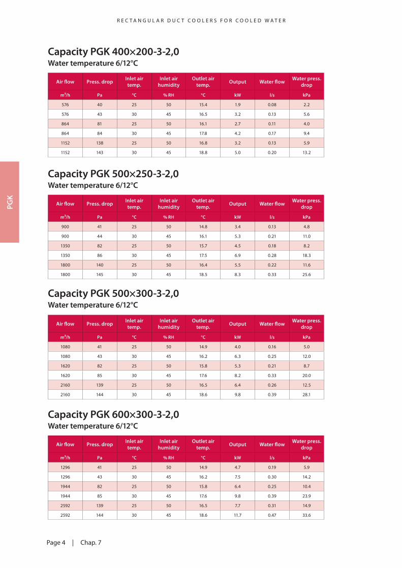
Capacity PGK 400×200-3-2,0Water temperature 6/12°C
Air flow Press. drop Inlet air temp.
Inlet air humidity
Outlet air temp. Output Water flow Water press.
drop
m³/h Pa °C % RH °C kW l/s kPa
576 40 25 50 15.4 1.9 0.08 2.2
576 43 30 45 16.5 3.2 0.13 5.6
864 81 25 50 16.1 2.7 0.11 4.0
864 84 30 45 17.8 4.2 0.17 9.4
1152 138 25 50 16.8 3.2 0.13 5.9
1152 143 30 45 18.8 5.0 0.20 13.2
Capacity PGK 600×300-3-2,0Water temperature 6/12°C
Air flow Press. drop Inlet air temp.
Inlet air humidity
Outlet air temp. Output Water flow Water press.
drop
m³/h Pa °C % RH °C kW l/s kPa
1296 41 25 50 14.9 4.7 0.19 5.9
1296 43 30 45 16.2 7.5 0.30 14.2
1944 82 25 50 15.8 6.4 0.25 10.4
1944 85 30 45 17.6 9.8 0.39 23.9
2592 139 25 50 16.5 7.7 0.31 14.9
2592 144 30 45 18.6 11.7 0.47 33.6
Capacity PGK 500×250-3-2,0Water temperature 6/12°C
Air flow Press. drop Inlet air temp.
Inlet air humidity
Outlet air temp. Output Water flow Water press.
drop
m³/h Pa °C % RH °C kW l/s kPa
900 41 25 50 14.8 3.4 0.13 4.8
900 44 30 45 16.1 5.3 0.21 11.0
1350 82 25 50 15.7 4.5 0.18 8.2
1350 86 30 45 17.5 6.9 0.28 18.3
1800 140 25 50 16.4 5.5 0.22 11.6
1800 145 30 45 18.5 8.3 0.33 25.6
Capacity PGK 500×300-3-2,0Water temperature 6/12°C
Air flow Press. drop Inlet air temp.
Inlet air humidity
Outlet air temp. Output Water flow Water press.
drop
m³/h Pa °C % RH °C kW l/s kPa
1080 41 25 50 14.9 4.0 0.16 5.0
1080 43 30 45 16.2 6.3 0.25 12.0
1620 82 25 50 15.8 5.3 0.21 8.7
1620 85 30 45 17.6 8.2 0.33 20.0
2160 139 25 50 16.5 6.4 0.26 12.5
2160 144 30 45 18.6 9.8 0.39 28.1
PGK

Chap. 7 | Page 5
R E C T A N G U L A R D U C T C O O L E R S F O R C O O L E D W A T E R
Capacity PGK 600×350-3-2,0Water temperature 6/12°C
Air flow Press. drop Inlet air temp.
Inlet air humidity
Outlet air temp. Output Water flow Water press.
drop
m³/h Pa °C % RH °C kW l/s kPa
1512 41 25 50 14.9 5.5 0.22 7.3
1512 43 30 45 16.2 8.8 0.35 17.7
2268 82 25 50 15.8 7.4 0.29 12.9
2268 85 30 45 17.6 11.4 0.45 29.8
3024 139 25 50 16.5 9.0 0.36 18.6
3024 144 30 45 18.6 13.7 0.54 42.0
Capacity PGK 1000×500-3-2,0Water temperature 6/12°C
Air flow Press. drop Inlet air temp.
Inlet air humidity
Outlet air temp. Output Water flow Water press.
drop
m³/h Pa °C % RH °C kW l/s kPa
3429 42 25 50 14.9 12.4 0.49 9.1
3429 45 30 45 16.3 19.2 0.76 21.4
5144 82 25 50 15.9 16.3 0.65 15.6
5144 86 30 45 17.7 24.7 0.98 35.1
6858 140 25 50 16.7 19.5 0.77 22.1
6858 144 30 45 18.8 29.2 1.16 48.6
Capacity PGK 700×400-3-2,0Water temperature 6/12°C
Air flow Press. drop Inlet air temp.
Inlet air humidity
Outlet air temp. Output Water flow Water press.
drop
m³/h Pa °C % RH °C kW l/s kPa
1920 42 25 50 15.1 6.7 0.27 3.7
1920 44 30 45 16.4 10.5 0.42 8.8
2880 82 25 50 16.0 8.9 0.35 6.4
2880 85 30 45 17.8 13.5 0.54 14.3
3840 139 25 50 16.8 10.7 0.42 9.1
3840 143 30 45 18.9 16.0 0.64 19.8
Capacity PGK 800×500-3-2,0Water temperature 6/12°C
Air flow Press. drop Inlet air temp.
Inlet air humidity
Outlet air temp. Output Water flow Water press.
drop
m³/h Pa °C % RH °C kW l/s kPa
2743 42 25 50 14.8 9.9 0.40 6.8
2743 45 30 45 16.3 15.4 0.61 15.7
4115 82 25 50 15.9 13.1 0.52 11.5
4115 86 30 45 17.7 19.8 0.79 25.6
5486 140 25 50 16.6 15.7 0.62 16.2
5486 144 30 45 18.8 23.4 0.93 35.4PG
K

Page 6 | Chap. 7
R E C T A N G U L A R D U C T C O O L E R S F O R C O O L E D W A T E R
Capacity PGK 400×200-4-2,0Water temperature 6/12°C
Air flow Press. drop Inlet air temp.
Inlet air humidity
Outlet air temp. Output Water flow Water press.
drop
m³/h Pa °C % RH °C kW l/s kPa
576 54 25 50 14.6 2.1 0.08 1.4
576 58 30 45 14.9 3.8 0.15 3.9
864 109 25 50 14.9 3.2 0.13 2.8
864 114 30 45 16.0 5.1 0.20 6.8
1152 185 25 50 15.5 3.9 0.16 4.2
1152 194 30 45 17.0 6.2 0.25 9.8
Capacity PGK 600×300-4-2,0Water temperature 6/12°C
Air flow Press. drop Inlet air temp.
Inlet air humidity
Outlet air temp. Output Water flow Water press.
drop
m³/h Pa °C % RH °C kW l/s kPa
1296 55 25 50 13.8 5.5 0.22 3.2
1296 59 30 45 14.5 8.9 0.35 7.9
1944 110 25 50 14.5 7.6 0.30 5.9
1944 115 30 45 15.7 11.9 0.47 13.8
2592 187 25 50 15.2 9.4 0.37 8.7
2592 195 30 45 16.7 14.5 0.57 19.8
Capacity PGK 500×250-4-2,0Water temperature 6/12°C
Air flow Press. drop Inlet air temp.
Inlet air humidity
Outlet air temp. Output Water flow Water press.
drop
m³/h Pa °C % RH °C kW l/s kPa
900 56 25 50 13.3 4.1 0.16 3.8
900 59 30 45 14.1 6.5 0.26 8.7
1350 112 25 50 14.2 5.6 0.22 6.7
1350 116 30 45 15.4 8.6 0.34 14.8
1800 189 25 50 14.9 6.9 0.27 9.6
1800 197 30 45 16.5 10.5 0.42 21.2
Capacity PGK 500×300-4-2,0Water temperature 6/12°C
Air flow Press. drop Inlet air temp.
Inlet air humidity
Outlet air temp. Output Water flow Water press.
drop
m³/h Pa °C % RH °C kW l/s kPa
1080 56 25 50 13.3 5.0 0.20 4.1
1080 59 30 45 14.1 7.8 0.31 9.5
1620 112 25 50 14.2 6.7 0.27 7.3
1620 116 30 45 15.4 10.4 0.41 16.3
2160 189 25 50 14.9 8.2 0.33 10.6
2160 197 30 45 16.5 12.6 0.50 23.4
Capacity PGK 250×150-4-2,0 Please use VEAB Select at www.veab.com
PGK

Chap. 7 | Page 7
R E C T A N G U L A R D U C T C O O L E R S F O R C O O L E D W A T E R
Capacity PGK 600×350-4-2,0Water temperature 6/12°C
Air flow Press. drop Inlet air temp.
Inlet air humidity
Outlet air temp. Output Water flow Water press.
drop
m³/h Pa °C % RH °C kW l/s kPa
1512 56 25 50 13.6 6.6 0.26 3.0
1512 59 30 45 14.3 10.6 0.42 7.1
2268 111 25 50 14.4 9.1 0.36 5.4
2268 115 30 45 15.6 14.1 0.56 12.2
3024 188 25 50 15.1 11.1 0.44 7.8
3024 196 30 45 16.6 17.1 0.68 17.5
Capacity PGK 1000×500-4-2,0Water temperature 6/12°C
Air flow Press. drop Inlet air temp.
Inlet air humidity
Outlet air temp. Output Water flow Water press.
drop
m³/h Pa °C % RH °C kW l/s kPa
3429 59 25 50 12.9 16.8 0.67 6.2
3429 61 30 45 13.8 25.2 1.00 13.2
5144 114 25 50 13.9 22.2 0.88 10.4
5144 118 30 45 15.3 33.1 1.32 22.0
6858 192 25 50 14.7 26.7 1.06 14.7
6858 199 30 45 16.4 39.7 1.58 30.9
Capacity PGK 700×400-4-2,0Water temperature 6/12°C
Air flow Press. drop Inlet air temp.
Inlet air humidity
Outlet air temp. Output Water flow Water press.
drop
m³/h Pa °C % RH °C kW l/s kPa
1920 59 25 50 13.0 9.2 0.36 5.6
1920 61 30 45 13.9 13.9 0.55 12.1
2880 114 25 50 14.0 12.2 0.48 9.5
2880 118 30 45 15.4 18.3 0.73 20.3
3840 192 25 50 14.8 14.7 0.58 13.4
3840 198 30 45 16.5 21.9 0.87 28.6
Capacity PGK 800×500-4-2,0Water temperature 6/12°C
Air flow Press. drop Inlet air temp.
Inlet air humidity
Outlet air temp. Output Water flow Water press.
drop
m³/h Pa °C % RH °C kW l/s kPa
2743 58 25 50 13.5 12.2 0.48 3.0
2743 61 30 45 14.4 18.9 0.75 6.9
4115 112 25 50 14.4 16.3 0.65 5.2
4115 117 30 45 15.8 24.8 0.99 11.5
5486 189 25 50 15.1 19.7 0.78 7.4
5486 197 30 45 16.8 29.8 1.18 16.1PG
K

AQUA24TF RC RC-DO OPTIGO OP10
Page 8 | Chap. 7
R E C T A N G U L A R D U C T C O O L E R S F O R C O O L E D W A T E RR E G U L A T O R S A N D A C C E S S O R I E S
Regulators
AQUA Complete regulator with built-in room sensor. Floating control for controlling three-position actuators. Cascade connection with minimum limit for room temperature control. Can be equipped with external room and/or duct sensor and external setpoint adjustment. Temperature range 0 - 30°C, depending on the sensor employed.
AQUA24TF24V supply. The regulator has a built-in controlling anti-freeze protection with two alarm relays and automatic control for heating during stoppage.
REGIO MINI Complete regulator with built-in room sensor. Can be equipped with external room and/or duct sensors. Has two control outputs, e.g. for heating and cooling in sequence.
RC24V supply. 0…10V output control signal.DIP switches are used for basic 20 - 26°C setpoint setting. The basic setting can be adjusted by ±3°C by means of the setpoint knob.
RC-DO24V supply. 0…10V output control signal. The RC-DO has a back-lit display and a temperature range of 0 - 50°C.
OPTIGORegulator with display. One knob for all settings. For mounting on DIN rail. Operates with PT1000 sensor in the range of -20°C to + 40°C. Started/stopped with ”run” signal from the fan.
OP524V supply. 0...10V control signal output. Operates with one sensor (room or duct sensor). Can be reset for heating or cooling control.
OP1024V supply. Can be reset for 0…10V control signal output or 3-point control. Two control outputs, e.g. for heating and cooling in sequence. Input for two sensors and anti-freeze sensor. Supply air temperature control or room temperature control with cascade-controlled supply air. Anti-freeze con-trol with heating during stoppage. Output, e.g. for starting/stopping of fans via 230V~, 5A relay. Programmable one-week timer for controlling of both fan and heating/cooling. Terminal for external timer that extends the operating time. Can be equipped with external setpoint adjuster.
OP10-230Same functions as the OP10, but with 230V~ supply.
PGK

Chap. 7 | Page 9
R E C T A N G U L A R D U C T C O O L E R S F O R C O O L E D W A T E RR E G U L A T O R S A N D A C C E S S O R I E S
Accessories for AQUA
Product Range DesignDuct sensor TG-K330
0-30°C Degree of protection IP20
Room sensor TG-R430 with setpoint adjustment
0-30°C Degree of protection IP30
Room sensor TG-R530
0-30°C Degree of protection IP30
Room sensor TG-R630
0-30°C Degree of protection IP54
Trafo 60Totally enclosed transformer for wall mounting. Built-in two-pole fuse on secondary side.
Primary voltage 230V~ Secondary voltage 24V~ Max. rating 60 VA Degree of protection IP44
Product Range DesignDuct sensor TG-K3/PT1000
-30...+70°C Degree of protection IP20
Room sensor TG-R5/PT1000
0-50°C Degree of protection IP30
Room sensor TG-UH/PT1000
-30...+120°C Degree of protection IP65
Trafo 60Totally enclosed transformer for wall mounting. Built-in two-pole fuse on secondary side.
Primary voltage 230V~ Secondary voltage 24V~ Max. rating 60 VA Degree of protection IP44
Accessories for OPTIGO and REGIO
R E C T A N G U L A R D U C T C O O L E R S F O R C O O L E D W A T E RR E G U L A T O R S A N D A C C E S S O R I E S
PGK

Page 10 | Chap. 7
R E C T A N G U L A R D U C T C O O L E R S F O R C O O L E D W A T E RA C T U A T O R S A N D V A L V E S
Actuator RVAZ4-24
Valve ZTR
Valve ZTV
Actuators and valves for Kv 0.25 – 8.0 (110°C max)
Description Type
3-position actuator for ZTV/ZTR valves, degree of protection IP44 RVAZ4-24
Actuator for 0...10V signal for ZTV/ZTR valves, degree of protection IP44 RVAZ4-24A
Description Kv Type
2-way ½” valve 0.25 ZTV15-0.25
2-way ½” valve 0.4 ZTV15-0.4
2-way ½” valve 0.6 ZTV15-0.6
2-way ½” valve 1.0 ZTV15-1.0
2-way ½” valve 1.6 ZTV15-1.6
2-way ¾” valve 2.0 ZTV20-2.0
2-way ¾” valve 2.5 ZTV20-2.5
2-way ¾” valve 4.0 ZTV20-4.0
2-way ¾” valve 6.0 ZTV20-6.0
2-way 1” valve 8.0 ZTVB25-8.0
3-way ½” valve 0.25 ZTR15-0.25
3-way ½” valve 0.4 ZTR15-0.4
3-way ½” valve 0.6 ZTR15-0.6
3-way ½” valve 1.0 ZTR15-1.0
3-way ½” valve 1.6 ZTR15-1.6
3-way ¾” valve 2.0 ZTR20-2.0
3-way ¾” valve 2.5 ZTR20-2.5
3-way ¾” valve 4.0 ZTR20-4.0
3-way ¾” valve 6.0 ZTR20-6.0
3-way 1” valve 8.0 ZTRB25-8
PGK

0,01 0,02 0,03 0,05 0,08 0,1 0,2 0,3 0,4 0,5 0,8 l/s 1 2 3 5 8 10 20 30 40 50
108
654
3
2
1
0,05 0,08 0,1 0,2 0,3 0,4 0,5 0,8 1 2 3 4 5 8 10 20 30 40 50 80 100 200 m /h 3Flöde
TryckfallmVp kPa
10,8
0,60,50,4
0,3
0,2
0,1
kvs 0,63 1,0 1,6 105,64,22,7 16 27 392,110080
605040
30
20
108
654
3
2
Chap. 7 | Page 11
R E C T A N G U L A R D U C T C O O L E R S F O R C O O L E D W A T E RA C T U A T O R S A N D V A L V E S
Type of PGK Valve type Kv
PGK 400×200-3-2,0 2-way ZTV15-1,6 1.6
PGK 400×200-4-2,0 2-ways ZTV20-2,0 2.0
PGK 500×250-3-2,0 2-ways ZTV15-1,6 1.6
PGK 500×250-4-2,0 2-ways ZTV20-2,0 2.0
PGK 500×300-3-2,0 2-ways ZTV20-2,5 2.5
PGK 500×300-4-2,0 2-ways ZTV20-2,5 2.5
PGK 600×300-3-2,0 2-ways ZTV20-2,5 2.5
PGK 600×300-4-2,0 2-ways ZTV20-2,5 2.5
PGK 600×350-3-2,0 2-ways ZTV20-2,5 2.5
PGK 600×350-4-2,0 2-ways ZTV20-4,0 4.0
PGK 700×400-3-2,0 2-ways ZTV20-4,0 4.0
PGK 700×400-4-2,0 2-ways ZTV20-4,0 4.0
PGK 800×500-3-2,0 2-ways ZTV20-6,0 6.0
PGK 800×500-4-2,0 2-ways ZTVB25-8 8.0
PGK 1000×500-3-2,0 2-ways ZTV20-6,0 6.0
PGK 1000×500-4-2,0 2-ways ZTVB25-8 8.0
Guide for selection of valves and actuators for PGK coolers
Pressure drops across valves
110°C max. water temperatureActuator RVAZ4-24 (3-position) or RVAZ4-24A (0…10V) can be used for all ZTV/ZTR valves.
Flow
Pressure drop
R E C T A N G U L A R D U C T C O O L E R S F O R C O O L E D W A T E RA C T U A T O R S A N D V A L V E S
PGK
