petroleum and natural gas industries — external coatings for buried...
TRANSCRIPT

IS :2006 Doc: MTD 24 (4678)W
1
For Comments Only
Draft Indian Standard
Petroleum and natural gas industries — External coatings for buried or submerged pipelines used in pipeline transportation
of Gas and Liquid Hydrocarbons — Part 2: Fusion Bonded Epoxy Coatings
ICS 25.220.99; 75.200
_____________________________________________________________________ Not to be reproduced without the Last date for receipt of Permission of BIS or used as STANDARD comments is 22 Feb 2006 _____________________________________________________________________ FOREWORD
(Formal clause may be added later on) Corrosion is the physiochemical interaction between a metal and its environment that results in changes in the properties of the metal, and which may lead to significant impairment of the function of the metal. Corrosion affects every sector of industry as well as infrastructure. The avoidance and control of corrosion is, therefore, of the utmost importance. While formulating this standard International practices have been duly considered along with specific Indian scenario. This standard (Part 2) specifies requirements for qualification, application, testing and handling of materials for plant application of single layer fusion bonded epoxy (FBE) coatings applied externally for the corrosion protection of bare steel for use in pipeline transportation of gas and liquid hydrocarbon.
This standard has been issued in two parts the other part is as follows: Petroleum and natural gas industries — External coatings for buried or submerged pipelines used in pipeline transportation of Gas and Liquid Hydrocarbons — Part 1: Polyolefin coatings (3 – layer PE and 3-layer PP) For the purpose of deciding whether particular requirement of this standard is complied with the final value, observed or calculated, expressing the result of a test or analysis, shall be rounded off in accordance with IS 2:1960 `Rules for rounding off numerical values (revised)’. The number of significant places retained in the rounded off value should be the same as that of the specified valve in this standard.

IS :2006 Doc: MTD 24 (4678)W
2
1 Scope
This part of standard specifies the requirements for qualification, application, testing and handling of materials for plant application of single layer fusion bonded epoxy (FBE) coatings applied externally for the corrosion protection of bare steel for use in pipeline transportation systems for the petroleum and natural gas industries. High temperature coatings with a glass transition of above 120oC or FBE primer coatings for three- or multi- layer polyethylene or polypropylene coatings are not covered by this part
NOTE Pipes coated in accordance with this part of this Standard are considered suitable to further protection by means of cathodic protection.
2 REFERENCE The following standard contains provisions which through reference in this text, constitute provision of this standard. At the time of publication, the edition was valid. All standards are subject to revision, and parties to agreements based on this standard are encouraged to investigate the possibility of applying the most recent editions of the standards indicated below.
ISO 31-0, Quantities and units - Part 0: General principles
Doc:MTD 19(4672) : Line Pipe ISO 8501 all parts, Preparation of steel substrates before application of paints and related products - Visual assessment of surface cleanliness
ISO 8503 all parts, Preparation of steel substrates before application of paints and related products - Surface roughness characteristics of blast-cleaned steel substrates
ISO 10474, Steel and steel products - Inspection documents
ISO 11124 all parts, Preparation of steel substrates before application of paints and related products - Specifications for metallic blast-cleaning abrasives
ISO 11357 all parts, Plastics - Differential scanning calorimetry (DSC)
ISO 13623, Petroleum and natural gas industries - Pipeline transportation systems
ASTM Standard E 29-02 1 ), Standard Practice for Using Significant Digits in Test Data to DetermineConformance with Specifications
SSPC-AB 12), Mineral and Slag Abrasives
SSPC-AB 2, Cleanliness of Recycled Ferrous Metallic Abrasives
SSPC-AB 3, Ferrous Metallic Abrasive
SSPC-SP 1, Solvent cleaning

IS :2006 Doc: MTD 24 (4678)W
3
3 Terms and Definitions
For the purposes of this document, the following terms and definitions apply.
3.1 Applicator - Company which undertakes the coating application in accordance with the provisions of this standard.
3.2 Batch - Maximum quantity of 24 metric tons of epoxy powder produced during continuous production.
3.3 Batch certificate - Certificate of analysis issued by the manufacturer.
3.4 Certificate of Compliance - One of the types of documents defined by ISO 10474 to be issued in accordance with the purchasing requirements.
3.5 Cutback of pipe left uncoated at each end for joining purposes (that is welding).
3.6 Holiday coating discontinuity that exhibits electrical conductivity when exposed to a specific voltage.
3.7 Laboratory-coated Test Specimen - Specimen taken from a laboratory-prepared panel.
3.8 Manufacturer - Company responsible for the manufacture of coating material(s).
3.9 Manufacturer’s Specification - Document which specifies the characteristics, test requirements and application recommendations for the coating materials.
3.10 Pipe Diameter Length - Any length along the pipe axis equal to the specified outside diameter of the pipe.
3.11 Purchaser- Company responsible for providing the product order requirements.
3.12 Test report document that provides the quantitative test results for tests conducted in accordance with the requirements of this standard.
3.13 Test ring sample taken from production coated pipe.
4 Symbols and abbreviated terms
FBE fusion bonded epoxy Tg glass transition temperature in degrees Celsius (oC) �Tg variation of the glass transition temperature in degrees Celsius (oC) �H exothermic heat of reaction C percentage conversion of FBE coating

IS :2006 Doc: MTD 24 (4678)W
4
5 General requirements
5.1 Compliance to standard A quality system should be applied to assist compliance with the requirements of this part of standard. NOTE IS/ISO 9001 gives guidance on the selection and use of quality systems and ISO 14001 gives guidance on the selection and use of environmental management systems.
The applicator shall be responsible for complying with all of the applicable requirements of this part of standard. It shall be permissible for the purchaser to make any investigation necessary in order to be assured of compliance by the applicator and to reject any material that does not comply. 6 Information to be supplied by the purchaser
6.1 Principal information
The purchaser shall provide the following information:
a) Indian Standard designation and year of publication (IS : xxxx); b) pipe quantity, outside diameter, minimum wall thickness, minimum, maximum and nominal length, grade of steel; c) bare pipe standard or specification designation, that is IS : d) Minimum thickness and maximum permissible thickness of the coating; and e) cutback length and tolerances for both ends of pipe.
6.2 Supplementary information
If applicable, the purchaser shall specify the following information:
a) additional surface treatments; b) plant inspection by the purchaser; c) increased test ring length; d) test ring location; e) test frequency for additional test rings; f) additional markings;
g) handling procedures; h) storage procedures; j) waiver of test reports; and k) other special requirements.

IS :2006 Doc: MTD 24 (4678)W
5
7 Materials 7.1 Pipe
The pipe to be coated shall conform to the pipe standard or specification that is specified in the purchase order. CAUTION Pipe conforming to such standards or specifications does not necessarily have a surface condition that is appropriate for the application of FBE coating, that is temporary coating, sal t contamination, slivers.
7.2 Epoxy powder
7.2.1 General
The applicator shall use epoxy powder that is:
a) certified by the powder manufacturer to be in accordance with the requirements of 7.2.2 and 8.1, and compatible with the requirements of 9.2.2,
b) identified with the following:
i) powder manufacturer’s name; ii) product description; iii) mass of material; iv) batch number; v) location of manufacture; vi) manufacturing identification number; vii) temperature requirements for transportation and storage; viii) expiry date; and ix) year, month and day of manufacture.
c) handled, transported, and stored prior to use in accordance with the
powder manufacturer’s recommendations. 7.2.2 Properties
Each batch of epoxy powder shall be tested by the manufacturer in accordance with the requirements of Table 1. Test results shall be reported in accordance with ISO 10474:1999 subclause 2.3 and shall be made available to the applicator upon request.

IS :2006 Doc: MTD 24 (4678)W
6
Table 1 Minimum requirements for epoxy powder
Properties Requirements Test
method Cure time Within the manufacturer’s
specification A.2
Cure curve Within the manufacturer’s specification
A.2
Gel time Within 20% of manufacturer’s specification
A.3
Moisture content by mass 0,6% max A.5
Particle size Within the manufacturer’s specification maximum retained on 150 µm and 250 µm sieves
A.6
Density Within 50 g/l of manufacturer’s specification
A.7
Thermal characteristics Within the manufacturer’s specification
A.8
7.2.3 Packaging
The powder shall be contained in packaging that is clearly labeled to identify the items specified in 7.2.1 b).
8 Coating qualification and application
8.1 Coating qualification
The coating shall be qualified by the manufacturer through testing laboratory coated test specimens for each applicable test and by meeting the acceptance criteria.
The qualification shall be repeated at least once per year, or if there is a change in one or more of the following:
a) coating formulation; and b) location of product manufacture.
The tests to be conducted, the number of test specimens, the test methods to be used, and the acceptance criteria shall be as given in Table 2. These test results shall be reported in accordance with ISO 10474 subclause 2.3 and shall be made available to the applicator upon request.

IS :2006 Doc: MTD 24 (4678)W
7
Table 2 Minimum requirements for coatings qualification testing
Properties Requirements Number of
test specimens
Test method
Thermal characteristics Meets the
manufacturer’s specification
3
A.8
Cathodic disbondment 24 h, 65 oC ±3oC, -3.5 V
8mm maximum radius
3
A.9
24 h hot water adhesion 65o C ±3oC: Rating of 1 – 3.
3 A15
28 day hot water adhesion 65o C ±3oC: Rating of 1 – 3.
3 A-15
Cathodic disbondment 28 day, 20oC ±3oC, -1,5 V
8 mm maximum radius
3
A-9
Cross-section porosity Rating 1- 4 as per Fig. A-9
3 A-11
Interface porosity Rating 1-4 as per Fig. A-10
3 A-11
Flexibility at 0oC No cracking at 2.5οοοο
angle per pipe
5
A-12
Impact 2.5 J minimum 3 A-13
Strained coating, cathodic disbondment
28 day, 20oC ±3oC, -1.5 V
No cracking, No holiday
3
A-14
8.2 Preparation of laboratory-coated test specimens
Test specimens shall be mild steel and shall have dimensions in accordance with the applicable test method (see Annex A).
The substrate shall be abrasively blast cleaned with steel grit (ISO 11124-3) to provide a cleanliness in accordance with the requirements of ISO 8501-1 grade Sa3. The surface profile shall have a peak to trough height of between 60 µm and 100 µm as measured in accordance with the requirements of ISO 8503-4 (Stylus method), or ISO 8503-5 (Replica Tape method).
The thickness of coating on the completed test specimen shall be 500 µm±50 µm. This should be measured by a calibrated coating thickness gauge verified to ± 5 percent of full scale range.

IS :2006 Doc: MTD 24 (4678)W
8
8.3 Production application practices and equipment 8.3.1 General
The coating to be applied during production shall have been previously qualified in accordance with the requirements of 8.1.
8.3.2 Surface preparation
8.3.2.1 Initial preparation
All dirt, deleterious matter and contaminants, such as oil and grease shall be removed from the pipe prior to coating. If necessary, pipe shall be cleaned in accordance with the requirements of SSPC-SP1.
All steel defects and irregularities (e. g. laminations, slivers, scratches) shall be removed by an approved grinding method. Grinding of steel defects shall not reduce the wall thickness below the specified minimum wall thickness of the pipe.
All pipe shall be dry prior to entering the abrasive blast cleaning unit(s). Pipe temperature shall be at least 3 oC above the dew point immediately prior to abrasive blast cleaning.
8.3.2.2 Abrasive blast cleaning
The abrasives used in the coating plant shall be in accordance with the requirements of ISO 11124.
NOTE If the pipe to be coated is of a high strength grade e.g. X80, X100, X120, the applicator should use abrasives that are of a high enough hardness to provide the required cleanliness and surface profile.
The abrasives shall be maintained clean, dry and free from contaminants in accordance to SSPC-AB 1, SSPC-AB 2 and SSPC-AB 3 so as not to contaminate the substrate.
The cleanliness achieved prior to application shall be in accordance with the requirements of ISO 8501-1grade Sa 2½ (‘near white metal’).
The surface profile attained shall be within the range 50 µm to 100 µm. The surface profile, peak to trough height, shall be measured in accordance with the requirements of ISO 8503-4 (Stylus) or ISO 8503-5 (Replica Tape).
If grinding is required after blast cleaning, the maximum allowable area of grinding shall be 10 cm² per 1 m pipe length.
8.3.2.3 Surface cleanliness
The surface cleanliness shall be measured in accordance with the requirements of ISO 8502-3. The maximum allowable level shall be Class 2.

IS :2006 Doc: MTD 24 (4678)W
9
8.3.2.4 Surface pretreatment
When the applicator chooses a surface pretreatment (e. g. phosphoric acid and/or or chromate pretreatment), the pretreatment process shall be specified, and agreed upon with the purchaser. The pretreatment shall be applied in accordance with the requirements of the pre-treatment supplier's instructions.
When surface pretreatment is used for prequalification it must be used for production.
When surface pretreatment is not used, testing for the presence of soluble salts on pipe shall be undertaken in accordance with the requirements of ISO 8502-9. The maximum allowable level shall be 2 µg/cm².
If high levels of soluble salts are measured above 2 µg/cm², a surface pre-treatment cleaning process shall be agreed upon the applicator and the purchaser.
8.3.3 Application and curing temperatures
Application and curing temperatures of the external pipe surface shall be as selected by the applicator within the manufacturer's recommendation and shall not exceed 275oC.
CAUTION For grades over X80 the maximum curing temperature might effect the pipe properties.
8.3.4 Coating thickness
The minimum thickness of the coating and the maximum permissible thickness of the coating shall be 500 µm+100 µm.
� 0 µm 8.3.5 Cutback
The cutback length and tolerances for the FBE coating on both ends of the pipe should be as specified in the Table below.
Pipe diameter Cut back length < 500 mm 100 mm ± 10 mm � 500 mm 150 mm ± 20 mm
9 Inspection and testing 9.1 Inspection
If specified in the purchase order inspection shall be undertaken by the purchaser. All inspections shall be made at the place of application prior to shipment and shall be conducted without undue interference with the operation of the plant. The purchaser may require that the applicator set aside pipe as requested for inspection or testing, or both.

IS :2006 Doc: MTD 24 (4678)W
10
9.2 Testing
9.2.1 Gel time testing
For each pipe coating order, gel time tests shall be successfully completed on each batch of epoxy powder prior to its use for production coating, but not necessarily before production starts. Such tests shall be conducted in accordance with the requirements of A-3, and the acceptance criterion shall be as given in Table 1. Where the average gel time fails to conform to the specified requirements, the gel test shall be repeated using two additional samples taken from the batch. Where both retests conform to the specified gel time requirement, the powder batch shall be accepted. Where one or both retests fail to conform to the specified requirements, the powder batch shall be rejected.
9.2.2 In-coming epoxy powder and coating testing
The applicator shall conduct the sample preparation, testing, and evaluation of the epoxy powder and coating in accordance with the requirements of Table 3 at the application facility.
The minimum testing frequency shall be one sample on every vehicle shipment of epoxy powder received.
Prior to the use of the powder for production coating, laboratory-coated test specimens shall be prepared by the applicator at the proposed plant application temperature. The tests to be conducted, the number of test specimens to be used, the test methods to be used, and the acceptance criteria shall be as given in Table 3. The epoxy powder shall meet the requirements of Table 3 before its use for production coating. If a Table 3
test fails to conform to the specified requirements, the applicator shall have the option of repeating that specific test using two additional samples taken from the batch. If both retests conform to the specified test requirements, the powder batch shall be accepted. If one or both retests fail to conform to the specified requirements, the specific powder batch shall be rejected.

IS :2006 Doc: MTD 24 (4678)W
11
Table 3 — Minimum requirements for laboratory coating testing
Properties
Requirements Number of
specimens
Test method
Cathodic disbondment 24 h, 65 oC ±3oC, -3.5 V
8 mm radius
maximum
1
A-9
Cross section porosity
Rating 1-4 Figure A.9
1
A-11
Interface porosity
Rating 1-4 Figure A.10
1
A-11
Flexibility at 0oC No cracking
at 2.0o angle per pipe diameter
3
A-12
24 h hot water adhesion Rating 1-3 1 A-15
9.2.3 In-process inspection / measurement by applicator
9.2.3.1 Surface finish
The surface finish shall be monitored on each pipe during production to determine if the cleanliness is in accordance with the requirements of 8.3.2.3.
9.2.3.2 Surface profile
At least once every 4 h of production, the external surface profile on each pipes shall be measured using a profilometer, replicating film, or purchaser-approved equivalent. The profile shall be in accordance with the requirements of 8.3.2.2.
9.2.3.3 Visual inspection
After cleaning, each pipe shall be visually inspected for surface defects and surface imperfections that might cause holidays in the coating. Such surface imperfections shall be removed by grinding, provided that the remaining wall thickness is within specified limits. Pipe containing surface defects shall be rejected or repaired at the purchaser’s option.

IS :2006 Doc: MTD 24 (4678)W
12
9.2.3.4 Application temperature
The surface temperature of the pipe during the epoxy powder application shall be monitored, control led and recorded continuously within the limits agreed on by the applicator, the purchaser and the powder manufacturer.
Once the coating temperature is established, the temperature of every fifth pipe shall be taken and recorded.
Any change in the coating parameters that is line speed, may necessitate a modification in the method of temperature measurement.
9.2.3.5 Curing
The post-application temperature and the time interval between application and quenching shall be measured, recorded and controlled to ensure that the coating is being adequately cured. The minimum recording frequency shall be at start-up and once every hour of production thereafter.
9.2.3.6 Coating thickness
The coating thickness shall be measured at three random locations along each pipe length using a coating thickness gauge that has been calibrated at least once every working shift (to a maximum of 12 h) against a thickness standard that is within 10 % of the nominal coating thickness specified in the purchase order. Such measured thickness values shall be recorded.
If individual measured thickness values are less 500 µm, the coating thickness of the affected pipes shall be measured along the pipe length at intervals not exceeding 1 m.
If the coated pipe does not meet the requirements of this clause, it shall be stripped and recoated in accordance with the requirements of 10.3.
9.2.3.7 Holiday inspection
9.2.3.7.1 General
The entire coated surface of each length of pipe shall be inspected with a holiday detector having a search electrode made of conducting rubber or phosphor bronze wire.
For inspection, the direct current potential of the detector shall be set to exceed 5 V for each micrometer of nominal coating thickness. The detector shall be calibrated at least once every working shift (to a maximum of 12 h).
Inspection shall be performed when the temperature of the coating is less than 100 oC.

IS :2006 Doc: MTD 24 (4678)W
13
9.2.3.7.2 Acceptance criteria
No holidays shall be permitted in finished coating.
Coated pipe having holidays shall be repaired by patching in accordance with the requirements of 10.2, provided that the number of holidays does not exceed the following:
a) 1 defect per metre length and maximum 6 defects per pipe If the quantity of holidays exceeds the applicable limit as specified above, or if the area of an
individual holidayis equal to or greater than 250 cm2, the affected pipe shall be stripped and recoated in accordance with the requirements of 10.3.
9.2.4 Production test rings
9.2.4.1 Facilities
The applicator shall have facilities available at the application plant for the preparation, testing, and evaluation of test ring samples for the tests required in Table 4.
9.2.4.2 Test rings
Test rings should be 500 mm – 600 mm in length and shall be obtained from locations at least 300 mm from a pipe end.
9.2.4.3 Testing requirements The minimum test frequency shall be one test ring per pipe diameter and specified wall thickness every working shift (to a maximum of 12 h).
For pipe that is stripped and recoated, at least one test ring of the stripped and recoated pipe shall be taken for each order item. Where specified in the purchase order, additional test rings shall be taken.
For each test ring, the tests to be conducted, the number of test specimens to be used, the test method to be used, and the acceptance criteria shall be as given in Table 4.

IS :2006 Doc: MTD 24 (4678)W
14
Table 4 Minimum requirements for production coating testing
Test Requirements Number of
Specimens Test Method
Degree of curea DSC – Delta Tg meets manufacturers specification
1 A-8
Porosity Rating 1-4 as per Figure A.9 and Figure A.10
1 A-11
Dry adhesiona Rating of 1 or 2 1 A-4
Impact 2.5 J minimum There shall be no holiday
1 A-13
Flexibilityb 2.0o No cracking at 0 oC. For 500 µm coating thickness
3 A-12
Hot water adhesion Rating of 1 – 3 (24 h at 65 oC)
1 A-15
Cathodic disbondment
8 mm radius maximum 24 h, 65 oC ± 3 oC, -3.5 V
1 A-9
Interface contamination
30 % maximum 1 A-10
a This test can be done on the pipe or on a test ring. b For greater coating thicknesses, testing to be done by agreement between the purchaser and applicator.
9.2.4.4 Retests
If a test fails to conform to the specified requirements, either
a) the test (see Table 4, Column 2) that failed shall be repeated using two additional test samples (see9.2.4.2) taken from the originally tested end of the affected pipe, or
b) all pipe coated after the previous acceptable test and prior to the next acceptable test
shall be stripped and recoated in accordance with the requirements of 10.3. If both retests conform to the specified requirements, the coated pipe shall be accepted.

IS :2006 Doc: MTD 24 (4678)W
15
If one or both of the retests fail to conform to the specified requirements all pipe coated after the previous acceptable test and prior to the next acceptable test shall be stripped and recoated in accordance with the requirements of 10.3 no further testing shall be permitte
NOTE By agreement with the purchaser and applicator the coating maybe deemed acceptable in those instances where inaccurate colours interface contamination test results have resulted due to the influence of the particular pretreatment used on the surface of the pipe prior to powder application.
9.3 Test results
Regardless of any waiver of test reports specified in the purchase order, the results of all tests required in 9.2 shall be available to the purchaser on request.
10 Repair of coated pipe
10.1 General
If required in clauses 9 or 12, coated pipe shall be repaired in accordance with the requirements of 10.2 or by stripping or recoating in accordance with the requirements of 10.3 whichever is applicable.
10.2 Repair of holidays
The repair of holidays shall conform to the recommendations of the manufacturer and the following requirements:
a) holidays, and the surrounding coating shall be cleaned by removing all rust, scale, dirt,
other detritus and loose coating; b) the cleaned areas, and an area of 50 mm surrounding the holiday, shall be suitably
roughened in accordance with the repair manufacturer’s recommendations; c) all dust and detritus shall be removed with a clean, dry cloth or brush;
d) areas of 25 mm in diameter or smaller shall be repaired with the powder manufacturer’s
recommended hot-melt patch stick, two-part coating, or the purchaser approved equivalent;
e) areas greater than 25 mm in diameter and less than 250 cm2 in area shall be repaired
with the powder manufacturer’s recommended two-part coating, or the purchaser-approved equivalent;
f) the minimum thickness of the repaired coating shall be in accordance with the requirements of 8.3.4;
g) all repairs shall be holiday tested in accordance with the requirements of 9.2.3.7;
h) the number of repairs per length of pipe shall be recorded.
IS :2006 Doc: MTD 24 (4678)W
16
10.3 Stripping and recoating
The pipe surface shall be cleaned by a combination of heating to a temperature not to exceed 275oC, scraping brushing and or abrasive blast cleaning. All previous coating shall be removed prior to the normal cleaning and coating process. Recoating shall be performed in accordance with the requirements of 8.3 and 9.
The identity of each stripped pipe shall be recorded.
11 Markings
11.1 General
Coated pipe shall be marked in accordance with the requirements of 11.2 and with any additional markings specified in the purchase order. Additional markings as desired by the applicator shall be by agreement.
11.2 Required markings
The following markings shall be placed on the coating:
a) applicator’s name or mark;
b) Indian Standard designation and year of publication;
c) markings required by the applicable pipe specification or standard;
d) date of coating application; and
e) pipe number
Marking shall be carried out using a suitable method such as stencil painting or printing, to ensure legible and indelible identification.
12 Handling and storage
12.1 Handling
Coated pipe shall be handled in a manner that avoids damage to the pipe and coating. If specified in the purchase order, the applicator shall submit details of the handling procedures; such procedures shall include loading requirements where the applicator is responsible for loading.
Pipe that is damaged during processing shall be repaired in accordance with the requirements of the applicable pipe specification or standard.
Coating that is damaged after the holiday inspection (see 9.2.3.7) shall be repaired in accordance with the requirements of 10.
Coated pipe shall have full encirclement separators around each length. Such separators shall be sized and located in order to prevent damage to the coating.

IS :2006 Doc: MTD 24 (4678)W
17
12.2 Storage If specified in the purchase order, the applicator shall submit details of the facilities and the methods to be used for yard storage.
13 Test reports and certificates of compliance
Unless specified in the purchase order that test reports are waived, the applicator shall furnish test reports to the purchaser in accordance with ISO 10474.
The applicator shall furnish certificates of compliance stating that the coating has been manufactured, applied, inspected, and tested in accordance with the requirements of this part of ISO 21809 and any other requirements specified in the purchase order; and the results of the coating tests and other required tests have been found to conform to such requirements.

IS :2006 Doc: MTD 24 (4678)W
18
Annex A
Test methods
A-1 General
This annex contains all the test methods referenced in the main body of this part of ISO 21809.
A-2 Cure time of the epoxy powder
A-2.1 Equipment
The equipment shall consist of the following:
a) hotplate, controllable to within 3 oC;
b) metal plate, approximately 25 mm × 150 mm × 150 mm;
c) contact thermometer;
d) timing device;
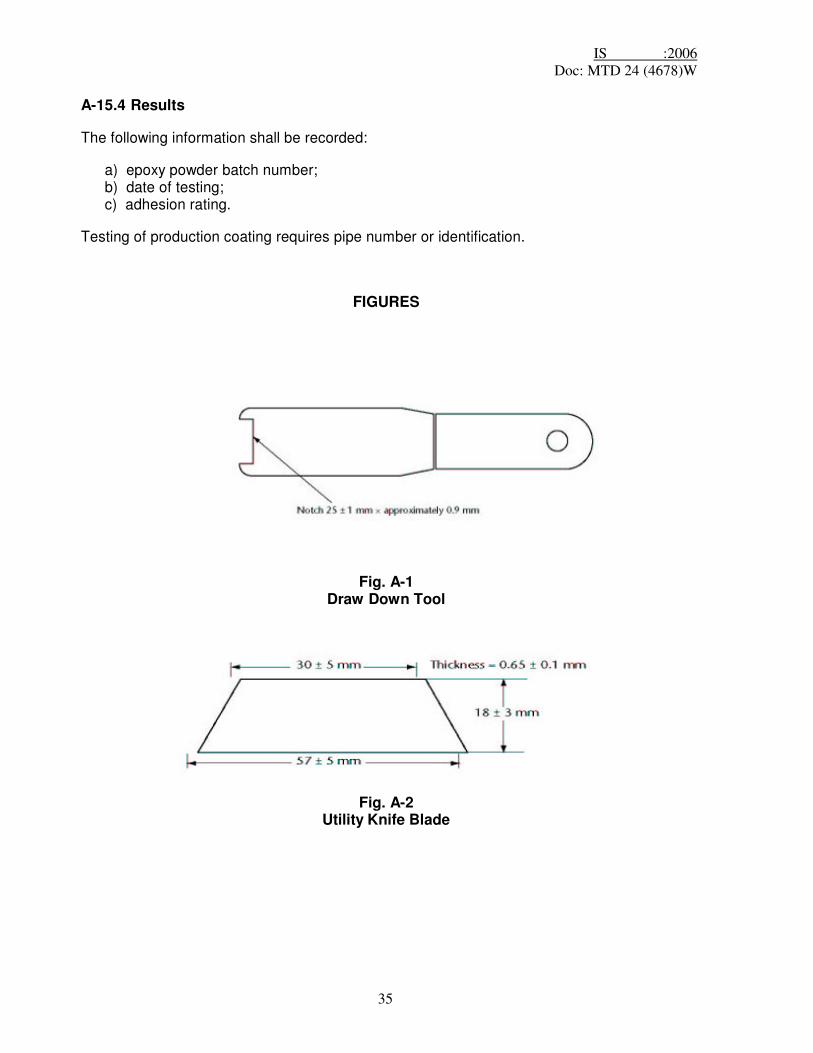
e) draw-down tool (see Figure A.1);
f) spatula;
g) Differential Scanning Calorimeter (DSC) with cooling accessory;
h) utility knife having a length, without the blade, of 135 mm ± 20 mm and a one-piece
metal blade having dimensions as shown in the following sketch and an exposed cutting edge of 25 mm ± 5 mm.(Figure A.2).
Figure A.1 — Draw down tool
Figure A.2 — Utility knife blade

IS :2006 Doc: MTD 24 (4678)W
19
A-2.2 Procedures
A-2.2.1 Heat and maintain the metal plate temperature at 232 oC ± 3 oC.
A-2.2.2 Use the draw-down tool to deposit a film of epoxy powder on the metal plate, aiming at a film thickness of 300 µm to 400 µm. Start the timing device at the instant of powder deposition on the hotplate surface.
A-2.2.3 Before the film has gelled completely, scribe the film generally as shown in Figure A.3, using the utility knife or spatula to produce 10 strips of coating.
A-2.2.4 Following 10 s ± 1 s after the timing device has started, using the utility knife, remove a strip of coating and immediately quench it in cold water.
A-2.2.5 For each additional 10 s ± 1 s of elapsed time, repeat the operation required by A.2.2.4. Remove the coating strips in sequential order following the direction of film drawn, starting at the beginning of the draw.
A-2.2.6 Using the differential scanning calorimeter, determine the change in Glass Transition value, (�Tg) or the percentage conversion, C, in accordance with the requirements of A.8.4.3.1 or A.8.4.3.2, respectively.
A-2.2.7 As specified by the powder manufacturer, plot time versus �Tg or time versus the percentage conversion.
Figure A.3 — Cure film
A-2.3 Results
The following information shall be recorded:
a) epoxy powder batch number;
b) date of testing;
c) time in seconds corresponding to a �Tg of 2oC, or the time in seconds corresponding to a conversion of 99%.

IS :2006 Doc: MTD 24 (4678)W
20
A-3 Gel time of the epoxy powder
A-3.1 Equipment
The equipment shall consist of the following:
a) hotplate controllable to within 3oC;
b) metal plate placed on top of the hotplate;
c) stopwatch or electric timing device capable of measuring 0.1 s intervals;
d) draw down tool (see Figure A.1).
A-3.2 Procedures
A-3.2.1 Conduct three tests and average the results.
A-3.2.2 Heat and maintain the temperature of the metal plate surface that will be in contact with the powder at a temperature of 205oC ± 3 oC.
A-3.2.3 Cover the bottom 25 mm of the draw-down tool with epoxy powder.
A-3.2.4 In a smooth motion, deposit and draw the epoxy powder across the metal plate while holding the tool at an angle of approximately 45o to the metal plate, thereby creating a tongue of epoxy powder approximately 25 mm wide.
NOTE The target thickness of the cured film is 300 µm to 400 µm.
A-3.2.5 Start the timing device and deposition of epoxy powder on the metal plate surface simultaneously.
A-3.2.6 Applying light pressure on the draw-down tool, repeatedly draw the edge of the tool through the melted epoxy powder. Stop the timing device when the tool rides up on the gelled epoxy powder and no longer contacts the metal plate.
A-3.3 Results
The following information shall be recorded:
a) epoxy powder batch number;
b) date of testing;
c) gel time in seconds.

IS :2006 Doc: MTD 24 (4678)W
21
A-4 Dry adhesion test
A-4.1 Equipment
The following equipment is required
a) utility knife, see A.2.1 h).
A-4.2 Test specimens Test can be carried out in situ on pipe or on laboratory sample / test ring.
A-4.3 Procedures
A-4.3.1 Inscribe a V cut with two 20 mm lines intersecting at approximately 5 mm from their ends at 30o to 45o.
A-4.3.2 Insert the blade of the knife at the point of the V cut, 45o to the surface, then with an upward flicking action attempt to dislodge the coating within the V. If little or no coating is removed, repeat this action within the V at least 4 times to confirm the integrity of the coating. A-4.3.3 Examine the appearance of the disbonded surface and compare with the following rating.
a) Coating is not removed cleanly at any point in the V-cut. The entire profile
contains some adherent coating; b) Coating is removed in small chips with some difficulty. Substantial coating remains
adherent to the surface profile; c) Coating is removed in chips which are slightly larger in area to the knife point inserted
under the coating. Some of the coating remains adherent to the surface of the steel within the V cut; and
d) Coating is removed with no chipping of the coating and minimal resistance. No coating remains adherent to the steel within the V cut.
A-4.4 Results
The following information shall be recorded:
a) epoxy powder batch number;
b) date of testing;
c) adhesion rating.
Testing of production coating requires pipe number or identification.

IS :2006 Doc: MTD 24 (4678)W
22
A-5 Moisture content of the epoxy powder — mass loss A-5.1 Procedure A (manual procedure)
A-5.1.1 Equipment
The equipment shall consist of the following:
a) oven controllable to within 3oC; b) balance accurate to 0.001 g; c) desiccator; d) sample container.
A-5.1.2 Procedures
A-5.1.2.1 Weigh the sample container to the nearest 0.001 g. Transfer approximately 10 g of epoxy powder into the sample container. Weigh the sample container and epoxy powder to the nearest 0.001 g.
A-5.1.2.2 Place the sample container with the epoxy powder into the oven for a maximum of 2 h at 105oC ±3 oC.
Remove the container from the oven, and place it in the desiccators to cool. Weigh the sample container when it has cooled to 20oC ± 3oC, and then return it to the desiccators; repeat at intervals of 60 min ± 10 min until two consecutive mass determinations are within 0.001 g.
A-5.1.2.3 Calculate the percentage of moisture using the following formula:
B � C M = ------------- x100 (1)
B � A
where
M is the percentage of moistur B is the initial mass of sample container and epoxy powder (g) C is the final mass of sample container and epoxy powder (g) A is the mass of sample container (g)
A-5.2 Procedure B (automatic procedure)
The moisture content of the epoxy powder shall be determined using a machine that automatically determines moisture content by mass loss.
A-5.3 Results
The following information shall be recorded:
a) epoxy powder batch number; b) date of testing; c) procedure used; d) percentage of moisture content.

IS :2006 Doc: MTD 24 (4678)W
23
A-6 Particle size of the epoxy powder A-6.1 Equipment
The equipment required shall consist of the following:
a) air-jet sieving unit with vacuum cleaner attachment and 150 µm and 250 µm screens; b) balance accurate to 0.01 g.
A-6.2 Procedures
A-6.2.1 Weigh the sieve and one screen to the nearest 0.01 g. Place approximately 20 g of epoxy powder onto the top of the screen, and record the weight of the powder to the nearest 0.01 g.
A-6.2.2 Place the sieve into the sieving unit, cover the unit, and secure it. Operate the sieving unit for 3 min and remove the cover.
A-6.2.3 Remove the sieve, and weigh it to the nearest 0.01 g.
A-6.2.4 Calculate the percentage of epoxy powder retained on the screen using the following formula �
100 P = ----------- (F - I ) (2) M
where
P is the percentage of epoxy powder retained; M is the initial mass of powder placed on screen (g); F is the final mass of sieve, screen, and retained powder (g);and I is the initial mass of sieve and screen (g).
A-6.2.5 Repeat, using the other screen.
A-6.3 Results The following information shall be recorded:
a) epoxy powder batch number; b) date of testing; and c) the percentage of powder retained for each screen size.
A-7 Density of the epoxy powder
A-7.1 General
At the option of the applicator, the density of the epoxy powder shall be determined using the procedure described in either A-7.2.2 or A-7.2.3. The test temperature shall be 20oC ± 3oC.
NOTE The choice of procedure used is at the option of the applicator.

IS :2006 Doc: MTD 24 (4678)W
24
A-7.2 Procedure A (manual procedure)
A-7.2.1 Equipment
The equipment shall consist of the following:
a) balance accurate to 0.01 g; b) 100 ml volumetric flask; and c) mineral spirits.
A-7.2.2 Procedures
A-7.2.2.1 Weigh the flask to the nearest 0.01 g.
A-7.2.2.2 Add approximately 20 g of epoxy powder to the flask, and weigh the flask plus epoxy powder to the nearest 0.01 g.
A-7.2.2.3 Add sufficient mineral spirits to cover and wet the epoxy powder. Stopper the flask, and agitate it for several minutes, ensuring that neither air pockets nor lumps of powder exist. Wash the stopper and walls of the flask with mineral spirits until they are free of powder and the flask is filled to the 100 ml level. Weigh the flask plus epoxy powder and mineral spirits to the nearest 0.01 g.
A-7.2.2.4 Empty the flask. Clean and dry the flask, add 100 ml of mineral spirits, and weigh the flask plus mineral spirits to the nearest 0.01 g.
A-7.2.2.5 Calculate the density of the mineral spirits using the following formula:
P= 10( Mfs � Mf ) (3)
where
P is the density of mineral spirits (g/l); Mfs is the mass of flask plus mineral spirits (g);and Mf is the mass of flask (g).
A-7.2.2.6 Calculate the density of the epoxy powder using the following formula:
Mfp � Mf Pp = -------------------- (Mfps� Mfp) 0.1 � ----------------- (4) Ps

IS :2006 Doc: MTD 24 (4678)W
25
Where
Pp is the density of epoxy powder (g/l); Mfp is the mass of flask plus epoxy powder (g); Mf is the mass of flask (g); Mfps is the mass of flask plus epoxy powder and mineral spirits (g); and Ps is the density of mineral spirits (g/l).
A-7.3 Procedure B (automatic procedure)
The density of the epoxy powder shall be determined using an air or helium pycnometer.
A-7.4 Results
The following information shall be recorded:
a) epoxy powder batch number; b) date of testing; c) procedure used; d) type of pycnometer used for Procedure B;and e) density of the epoxy powder in g/l.
A-8 Thermal analysis of epoxy powder and cured coating film
A-8.1 General
By thermal analysis the uncured epoxy-powder and the cured coating film are characterized.
The method to be used is Thermal-Scanning-Calorimetry (DSC). The general procedure and definitions are given in ISO 11357-1. Reference is made to this standard. General handling and calibration shall be performed as in ISO 11357-1 unless stated differently in this method.
A-8.2 Equipment
The equipment shall consist of the following:
a) differential- scanning calorimeter (DSC) with cooling accessory; b) balance accurate to 0,1 mg; c) sample encapsulating press; d) aluminium pans with covers; and e) dry gas supply of N2, analytical grade.
A-8.3 Procedures and measurement for epoxy powder
A-8.3.1 Measurement
a) Heat the sample from 25oC ± 5oC to 70oC ± 5oC at a rate of 20oC/min, then immediately cool the sample to 25oC ± 5oC. b) Heat the sample from 25oC ± 5oC to 275oC ± 5oC at a rate of 20oC/min, then immediately cool the sample to 25oC ± 5oC. c) Heat the sample from 25oC ± 5oC to Tg + 40oC (typically 150oC) at a rate
of 20oC/min, then immediately cool the sample to 25oC ± 5oC.

IS :2006 Doc: MTD 24 (4678)W
26
For certain epoxy powders different heating cycles might be necessary according to instructions of the epoxy powder manufacturer.
A-8.3.2 Evaluation of results
A-8.3.2.1 Glass transition temperature Tg
The Tg is calculated at the point of inflection intersection (Figure A.4).
By evaluating run (b) the Tg of the uncured powder is obtained = Tg1. By evaluating run (c) the Tg of the cured material is obtained = Tg2.
A-8.3.2.2 Heat of reaction of epoxy powder
The exothermic heat of reaction (�H) is obtained by integrating the exothermic peak of the DSC-scan.
Figure A.4 — Examples of thermal scans on epoxy powder A-8.4 Procedures and measurement for coating sample
A-8.4.1 General
A representative sample of the cured film is taken.
Weigh in 10 mg ± 3 mg to an accuracy of 0,1 mg. The pan is sealed with the cover. Determine final weight after sealing.
Place the sample and the reference sample in the DSC cell and purge with dry, N2 gas.
A-8.4.2 Measurement
a) Heat the sample from 25oC ± 5oC to 110oC ± 5oC at a rate of 20oC/min and hold for
1.5 min, then cool the sample to 25oC ± 5oC. b) Heat the sample from 25oC ± 5oC to 275oC ± 5oC at a rate of 20oC/min, then cool the sample to 25oC ± 5oC. c) Heat the sample from 25oC ± 5oC to Tg + 40oC (typically 150oC) at a rate of 20oC/min,
then cool the sample to 25oC ± 5oC.
For certain epoxy-powders different heating cycles might be necessary according to instructions of the epoxy- powder manufacturer.
NOTE Samples taken from pipes which have been stored or buried shall be dried before testing.

IS :2006 Doc: MTD 24 (4678)W
27
A-8.4.3 Evaluation of results
A-8.4.3.1 Glass transition temperature Tg
The Tg is calculated in the same way as for the epoxy powder for run 3 (b) and 3 (c); Figure A.5
where
Tg 3 is Tg of run 3(b) (oC)
Tg 4 is Tg of run 3(c) (oC)
For coatings, determine the change in Tg value using the following formula:
�Tg = Tg4 �Tg3 where
�Tg is change in Tg value (oC)
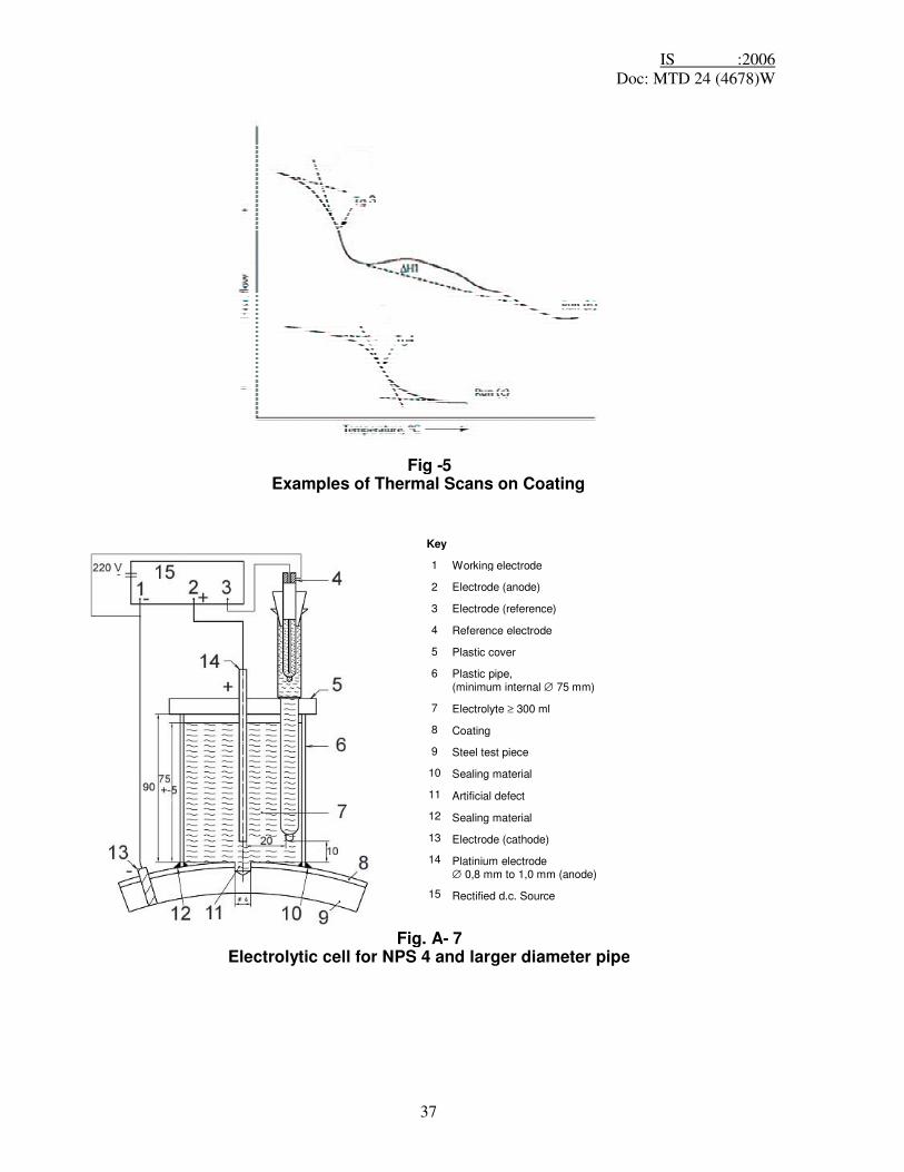
Figure A.5 — Examples of thermal scans on coating A-8.4.3.2 Residual heat of reaction of cured coating
The exothermic heat of reaction is obtained by integrating the exothermic peak of the DSC-scan 4 b; = �H1.
In a fully cured coating film there should be no residual heat of reaction be visible.
�H is exothermic heat of reaction of the powder (run 3.b)
�H1 is exothermic heat of reaction of the coating film (run 4.b)
� H � �H1 C = ---------------------- �H x 100 Where C is degree of conversion (%); �H is exothermic heat of reaction of the powder (run 3.b);and �H1 is exothermic heat of reaction of the coating film (run 4.b).

IS :2006 Doc: MTD 24 (4678)W
28
A-8.5 Results The following information shall be recorded:
a) Type of material and batch number; b) Date of testing; c) Type of DSC equipment; d) For the epoxy-powder Tg1, Tg2, �H; and e) For the cured coating film Tg3, Tg4, �Tg, �H1 and C.
Testing of production coating requires pipe number or identification.
A-9 Cathodic disbondment of the coating
A-9.1 Equipment
The equipment shall consist of the following:
a) rectified dc power supply with controlled voltage output; b) hotplate with a steel tray containing sand or steel grit/shot controllable to within 3oC, or an oven controllable to within 3oC; c) calomel reference electrode; d) 0.8 mm platinum wire electrode; e) 75 mm ± 3 mm ID plastic cylinder; f) percent sodium chloride solution in distilled water; g) utility knife, see A.2.1 h); and h) 3 mm or 3.2 mm drill bit (see Figure A-6).
Figure A-6 — Production of artificial defect A-9.2 Test specimens
Laboratory-coated test specimens shall be approximately 6.4 mm × 100 mm × 100 mm. Specimens from test rings shall be approximately 100 mm × 100 mm × pipe wall thickness.
A-9.3 Procedures
A-9.3.1 Use only test specimens that are confirmed to be holiday-free with a holiday detector set at a minimum of 1 800 V.
A-9.3.2 Drill either a 3.0 mm or 3.2 mm diameter holiday in the centre of the test specimen through the coating to expose the steel substrate (see Figure A.6).
A-9.3.3 Centre the plastic cylinder over the holiday and apply a sealant to form a water-resistant seal.
A-9.3.4 Add to the cylinder at least 300 ml of the sodium chloride solution that has been preheated to the test temperature. Mark the solution level on the cylinder. Insert the electrode into the solution and connect it to the positive wire from the dc power supply. Attach the negative wire from the d.c. power supply to a bare spot prepared on the test specimen.

IS :2006 Doc: MTD 24 (4678)W
29
A-9.3.5 Apply voltage (negative with respect to the calomel reference electrode) to the test specimen, and maintain constant temperature under one or more of the following test conditions, as given in Table 2, Table 3, and Table 4:
a) 1.5 V, 20oC ± 3oC, for a minimum of 28 d;
b) 3.5 V, 65oC ± 3oC, for a minimum of 24 h.
Maintain the solution level by the addition of distilled water as required (see Figure A.7 and Figure A.8).
A-9.3.6 Upon test completion, dismantle the test cell, air cool the specimen to 20oC ± 3oC, and evaluate the cathodic disbondment characteristics of the test specimen within 1 h of the removal from heat.
A-9.3.7 Using the utility knife, make 8 radial cuts through the coating to the substrate. Such cuts shall extend at least 20 mm from the centre of the holiday.
A-9.3.8 Insert the tip of the blade of the utility knife under the coating at the holiday. Using a levering action, chip off the coating. Continue until the coating demonstrates a definite resistance to the levering action.
A-9.3.9 Measure the disbonded distance from the edge of the original holiday along each radial cut, and average such measured values.
Figure A.7 — Electrolytic cell for NPS 4 and larger diameter pipe
Figure A.8 — Electrolytic cell for pipe smaller than NPS 4 diameter pipe A-9.4 Results
The following information shall be recorded:
a) epoxy powder batch number; b) date of testing; and c) average disbondment value in mm.
Testing of production coating requires pipe number or identification.
A-10 Interface contamination of the coating
A-10.1 Equipment
The equipment shall consist of the following:
a) stereo microscope; b) utility knife, see A.2.1 h).

IS :2006 Doc: MTD 24 (4678)W
30
A-10.2 Test specimens
Test specimens shall be approximately 25 mm × 200 mm × pipe wall thickness, with the 200 mm dimension parallel to the axis of the pipe.
A-10.3 Procedure
A-10.3.1 Use the utility knife to remove an approximately 3 mm × 20 mm piece of coating from the test specimen bent in accordance with the requirements of A-11.3.1.
A-10.3.2 Examine the metal interface side of the coating with the stereo microscope at 40× magnification. Estimate the percentage of interface contamination.
A-10.4 Results
The following information shall be recorded:
a) epoxy powder batch number; b) date of testing; c) percentage of interface contamination.
Testing of production coating requires pipe number or identification.
A-11 Porosity of the coating
A-11.1 Equipment
The equipment shall consist of the following:
a) stereo microscope (magnification 40x); b) bench vise or guided-bend jig; c) dry ice or a freezer; d) utility knife, see A.2.1 h). A-11.2 Test specimens
Laboratory-coated test specimens shall be approximately 6.4 mm × 25 mm × 200 mm. Specimens from test rings shall be approximately 25 mm × 200 mm × pipe wall thickness, with the 200 mm dimension parallel to the axis of the pipe.
A-11.3 Procedures
A-11.3.1 Cool the test specimen to at least –30 oC and bend it approximately 180o in the bench vise or guided-bend jig. A-11.3.2 Pry off a piece of coating from the bent test specimen, and examine the coating for porosity at 40× magnification.
A-11.3.3 Compare and rate the porosity present in the coating with the rating scale shown in figure A.9 and figure A.10

IS :2006 Doc: MTD 24 (4678)W
31
Figure A-9 — Maximum allowable cross-section porosity
Figure A-10 — Maximum allowable interface porosity A-11.4 Results
The following information shall be recorded:
a) epoxy powder batch number; b) date of testing; c) cross-section porosity rating; and d) interface porosity rating.
Testing of production coating requires pipe number or identification.
A-12 Flexibility of the coating
A-12.1 Equipment
The equipment shall consist of the following:
a) hydraulic press; b) bending mandrels with fixed radii; c) freezer; and d) strain gauges (if applicable). A-12.2 Test specimens
Laboratory-coated test specimens shall be approximately 6.4 mm × 25 mm with a minimum length of 200 mm. Specimens from test rings shall be the pipe wall thickness with a width of 25 mm and a minimum length of 200 mm. The length of 200 mm dimension shall be parallel to the axis of the pipe.
A-12.3 Procedures
A-12.3.1 Smooth the coating on the edge of the sample to remove any potential stress risers. Place the test specimen in the freezer; cool it to within 3oC of the powder manufacturer’s certified minimum flexibility test temperature of 0oC, and hold it within that temperature range for a minimum of 1 h.
A-12.3.2 Determine the sample thickness (t), which includes the specimen thickness and any curvature, by placing the specimen on a flat surface and measuring the thickness as shown in Figure A.11.
A-12.3.3 Determine the mandrel radius that corresponds to an angle of deflection of 2o per pipe diameter length by using the applicable formula from the following:
R = 28.15t
where
R is the mandrel radius (mm) t is the sample thickness (mm)

IS :2006 Doc: MTD 24 (4678)W
32
A-12.3.4 Bend the test specimen over a mandrel whose radius is not larger than that determined in accordance with the applicable requirements of A.12.3.3. Bend the specimen such that the operation lasts no longer than 10 s and is completed within 30 s of the test specimen having been removed from the freezer.
NOTE Where the sample exhibits peaking the % strain can be calculated by the use of stain gauges attached to the test specimen.
A-12.3.5 Warm the bent test specimen to 20oC ± 5 oC, and hold it in this temperature range for a minimum of 2 h. Within the next hour, visually inspect it for the presence of cracks.
Figure A-11 — Effective strap thickness diagram A-12.4 Results
The following information shall be recorded:
a) epoxy powder batch number; b) date of testing; c) specified angle of deflection; and d) cracking, if any.
Testing of production coating requires pipe number or identification.
A-13 Resistance to impact of the coating
A-13.1 Equipment
The equipment shall consist of the following:
a) impact tester having the following features:
i) 1 kg falling mass; ii) 15.8 mm diameter ball-bearing tup; iii) 1 m long graduated slotted tube; iv) for laboratory-coated specimen testing, flat anvils hardened to 55 HRC ± 5 HRC; v) for testing specimens from test rings, an anvil of 40 mm radius hardened to 55 HRC ± 5 HRC; vi) attached wooden base measuring at least 600 mm × 600 mm × 600 mm, with the
top of the base being hardwood; b) d.c. holiday detector; c) freezer.
A-13.2 Test specimens
Laboratory-coated test specimens shall be approximately 6.4 mm × 25 mm × 200 mm. Specimens from test rings shall be approximately 25 mm × 200 mm × pipe wall thickness, with the 200 mm dimension parallel to the axis of the pipe.

IS :2006 Doc: MTD 24 (4678)W
33
A-13.3 Procedures A-13.3.1 Place the test specimen in the freezer, cool it to –30oC ± 3oC, and hold it in this temperature range for a minimum of 1 h. Place the cooled specimen in the impact tester, centred on the applicable anvil.
A-13.3.2 Using an impact energy of at least 2.5 J, impact the specimen three times, with the impact points located at least 50 mm from each other. The three impacts shall be completed within 30 s of removal of the test specimen from the freezer. The ball bearing shall be rotated to an unused location after a maximum of 10 impacts and replaced after a maximum of 200 impacts.
A-13.3.3 Allow the sample to warm to 20oC ± 5oC. Test for the presence of holidays with a d.c. holiday detector set at 1 750 V ± 250 V, or a wet-sponge holiday detector set at 67.5 V ± 4.5 V.
A-13.4 Results
The following information shall be recorded:
a) epoxy powder batch number; b) date of testing; c) applied impact energy value in joules; d) holiday detection voltage; e) number of holidays.
Testing of production coating requires pipe number or identification. A-14 Cathodic disbondment of strained coating
A-14.1 Equipment
The equipment shall meet the requirements of A-9.1 and A- 2.1, except that a 25 mm ± 2 mm ID plastic cylinder shall be used.
A-14.2 Test specimens
Test sample of at least 50 mm x 300 mm x 6 mm are prepared.
A-14.3 Procedures
A-14.3.1 Bend the test samples in accordance with the method detailed under flexibility test method (A.12) to give a deflection of 2.0oPPD.
A-14.3.2 Test the sample as detailed in the Cathodic disbondment 28 day test method (A.9) with the holiday at the apex of the bent sample, i.e. area of maximum strain.
A-14.3.3 After 28 days polarization, remove the electrolyte and plastics tube and remove excess moisture.
A-14.3.4 The area of coating exposed to the electrolyte shall be examined within 24 h and not exhibit signs of cracks, disbondment or pinholes and shall pass a holiday detection test as detailed in holiday detection test method (9.2.3.7).

IS :2006 Doc: MTD 24 (4678)W
34
A-14.4 Results The following information shall be recorded:
a) epoxy powder batch number; b) date of testing; and c) cracking, if any.
Testing of production coating requires pipe number or identification.
A-15 Hot water adhesion of the coating
A-15.1 Equipment
The equipment shall consist of the following:
a) temperature-controlled slow cooker or non corroding water bath; b) tap water; c) thermometer; and d) utility knife, see A-2.1 h). A-15.2 Test specimens
Laboratory-coated test specimens shall be approximately 6,4 mm × 100 mm × 100 mm. Specimens from test rings shall be approximately 100 mm × 100 mm × pipe wall thickness.
A-15.3 Procedures
A-15.3.1 For each test, use fresh tap water that has been heated to 65oC ± 3oC prior to immersion of the test specimens. Place the test specimens in the slow cooker or water bath, and submerge them fully in such preheated water. Submerge the test specimens for a minimum of 24 h at a water temperature of 65oC ± 3oC, and then remove them from the slow cooker or water bath.
A-5.3.2 While the test specimen is still warm, use the utility knife to scribe an approximately 30 mm × 15 mm rectangle through the coating to the substrate, then air cool the test specimen to 20oC ± 3oC. Within 1 h after removal from heat (see A -15.3.1), insert the tip of the utility knife under the coating at a corner of the scribed rectangle. Use a levering action to remove the coating. Continue inserting the tip of the knife and levering it under the coating until either all of the coating in the rectangle is removed or the coating demonstrates a definite resistance to the levering action.
A-15.3.3 Rate the adhesion of the coating within the rectangle as follows:
a) Rating 1 — coating cannot be removed cleanly; b) Rating 2 — less than 50 percent of the coating can be removed; c) Rating 3 — more than 50 percent of the coating can be removed, but the coating demonstrates a definite resistance to the levering action; d) Rating 4 — the coating can be easily removed in strips or large chips; and e) Rating 5 — the coating can be completely removed as a single piece.
IS :2006 Doc: MTD 24 (4678)W
35
A-15.4 Results
The following information shall be recorded:
a) epoxy powder batch number; b) date of testing; c) adhesion rating.
Testing of production coating requires pipe number or identification.
FIGURES
Fig. A-1
Draw Down Tool
Fig. A-2
Utility Knife Blade

IS :2006 Doc: MTD 24 (4678)W
36
Fig. A-3
Cure Film
Fig A-4
Examples of Thermal Scans on Epoxy Powder
IS :2006 Doc: MTD 24 (4678)W
37
Fig -5 Examples of Thermal Scans on Coating
Key 1
2
3
4
5
6
7
8
9
10 11 12 13 14
15
Working electrode Electrode (anode)
Electrode (reference)
Reference electrode
Plastic cover
Plastic pipe, (minimum internal ∅ 75 mm) Electrolyte ≥ 300 ml Coating Steel test piece
Sealing material
Artificial defect
Sealing material
Electrode (cathode)
Platinium electrode ∅ 0,8 mm to 1,0 mm (anode) Rectified d.c. Source
Fig. A- 7 Electrolytic cell for NPS 4 and larger diameter pipe

IS :2006 Doc: MTD 24 (4678)W
38
Fig. A- 8
Electrolytic cell for pipe smaller than NPS 4 diameter pipe
Key 1 Fluted and mill face mill ∅ 3 or 3.2 mm 2 Conic end 3 Coating 4 Steel
Fig. A-6 Production of artificial defect

IS :2006 Doc: MTD 24 (4678)W
39
Fig. A-9 Cross Section porosity
Fig. A-10 Interface Porosity

IS :2006 Doc: MTD 24 (4678)W
40
Fig. A-11
Effective strap thickness diagram